

Page 1
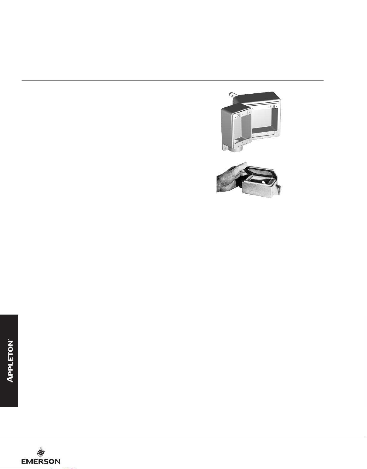
FS and FD Cast Hub Device Boxes
UNILETS™ for use with Threaded Rigid Conduit and IMC. All device boxes have ridge top construction.
CEC:
Listed for Ordinary Locations
Applications
• Accommodate wiring devices such as switches and
receptacles.
• Provide excellent service in areas where boxes are subject
to rough usage.
• Serve as pull boxes for conductors.
• Permit access to conductors for maintenance.
• Provide openings for making splices.
• Allow connections for branch conduit runs.
• Blank bodies for special conduit entrance arrangements.
Features
• Weatherproof, raintight and dust-tight when used with cast
gasketed covers.
• FSandFDboxestakestandardushwiringdevices.
• FD boxes take devices exceeding 1-5/8” in depth under
fastening ears.
• Malleable iron for high tensile strength and ductility — provides
greater resistance to impact and shock.
• Both malleable iron and aluminum boxes have ridge top
constructionforpositivecover/gasket/boxt.
• Accurately tapped, tapered threads for tight, rigid joints, ground
continuity.
• Complete selection of covers, receptacles, plugs, gaskets and
accessories.
• Covers have captive stainless steel screws to speed installation,
prevent "freezing" of screws.
• Ground screw at top of box for easy access.
• Cast Hub Boxes
— Available in single, two, three and four gang and tandem.
— Smooth, rounded integral bushing in each hub protects
conductor insulation.
• FD Blank Bodies for Brazed Hubs or Drill and Tapped Entries
— Available in single, two, three and four gang boxes.
— Drill and tapped entries.
— Brazed threaded hubs for threaded conduit from 1/2” thru
1-1/2” and brazed union hubs from 1/2” thru 1-1/4.
— Smooth, rounded integral bushing in each hub protects
conductor insulation.
— Ground screw at top of box for easy access.
COMMERCIAL AND INDUSTRIAL FITTINGS: CAST DEVICE BOXES
Standard Materials
• Cast hub device boxes and boxes for drilling and tapping:
malleable iron or copperfree (4/10 of 1% max.) aluminum
• Brazed hubs: malleable iron
• Covers: malleable iron, steel, or copperfree (4/10 of 1% max.)
aluminum
Standard Finishes
• Malleable iron boxes and covers: zinc electroplate
• Aluminum boxes and covers: natural
• Steel covers: zinc electroplate
• Screws: stainless steel
Options
• Enclosures drilled for 347 Volt devices. Add suffix -347.
ridge top of Appleton™ aluminum or malleable iron device box.
CEC Certifications and Compliances
• CSA Standard: C22.2 No. 18.1
• CSACertied:001472
Reference Data
• When ordering drilled and tapped openings or brazed hubs for
blank bodies, refer to FS and FD Cast Device Boxes Drilling and
Tapping Information pages.
Gasket is designed so that it “wraps around”
Result is a positive seal against moisture.
130
Visit our website at www.emerson.com or contact us at (800) 621-1506.
© November 2020
Page 2
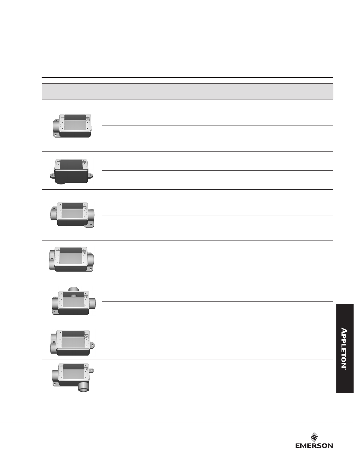
FS and FD Cast Hub Device Boxes
UNILETS™ for use with Threaded Rigid Conduit and IMC. All device boxes have ridge top construction.
CEC:
Listed for Ordinary Locations
Malleable Iron Aluminum
Size
1/2
3/4 1.02 (2.25) FS-2 0.34 (0.75) FS-2A
1 0.88 (1.94) FS-3 0.29 (0.64) FS-3A
1/2
3/4 1.18 (2.60) FD-2 0.42 (0.92) FD-2A
1 1.27 (2.80) FD-3 0.43 (0.94) FD-3A
1/2
3/4 0.73 (1.60) FSA-2 0.26 (0.58) FSA-2A
1/2
3/4 0.91 (2.00) FDA-2 0.30 (0.67) FDA-2A
1/2
3/4 1.09 (2.40) FSC-2 0.36 (0.80) FSC-2A
1 0.93 (2.06) FSC-3 0.32 (0.70) FSC-3A
1/2
3/4 1.27 (2.80) FDC-2 0.43 (0.94) FDC-2A
1 1.36 (3.00) FDC-3 0.45 (1.00) FDC-3A
Shallow
Deep
Shallow
Deep
Shallow
Deep
Weight kg (lb) Catalog Number Weight kg (lb) Catalog Number
0.88 (1.94) FS-1
1.22 (2.70) FD-1
0.77 (1.70) FSA-1
0.95 (2.10) FDA-1
0.95 (2.10) FSC-1
1.27 (2.80) FDC-1
Shallow
Deep
Shallow
Deep
Shallow
Deep
0.29 (0.64) FS-1A
0.41 (0.90) FD-1A
0.26 (0.57) FSA-1A
0.32 (0.70) FDA-1A
COMMERCIAL AND INDUSTRIAL FITTINGS: CAST DEVICE BOXES
0.32 (0.70) FSC-1A
0.43 (0.94) FDC-1A
1/2
Shallow
3/4 0.99 (2.20)
1/2
3/4 1.13 (2.50) FSCT-2 0.38 (0.84) FSCT-2A
1 1.02 (2.25) FSCT-3 0.34 (0.75) FSCT-3A
1/2
3/4 1.27 (2.80) FDCT-2 0.43 (0.94) FDCT-2A
1 1.41 (3.10) FDCT-3 0.47 (1.03) FDCT-3A
1/2
3/4 1.04 (2.30) FDD-2 0.35 (0.77) FDD-2A
3/4 Shallow 1.06 (2.34) FSL-2 Shallow 0.35 (0.78) FSL-2A
Use FD Unilets™ for wiring devices exceeding 1-5/8” in depth under fastening ears.
Shallow
Deep
Deep
0.77 (1.70) FSCC-1
1.13 (2.50) FSCT-1
1.36 (3.00) FDCT-1
0.99 (2.20) FDD-1
FSCC-21
Shallow
Shallow
Deep
Deep
0.26 (0.57) FSCC-1A
0.34 (0.74)
0.38 (0.84) FSCT-1A
0.45 (1.00) FDCT-1A
0.34 (0.74) FDD-1A
FSCC-21A
Visit our website at www.emerson.com or contact us at (800) 621-1506.
© November 2020
131
Page 3
FS and FD Cast Hub Device Boxes
UNILETS™ for use with Threaded Rigid Conduit and IMC. All device boxes have ridge top construction.
CEC:
Listed for Ordinary Locations
Malleable Iron Aluminum
Size
Weight kg (lb) Catalog Number Weight kg (lb) Catalog Number
1/2
3/4 0.82 (1.80) FSS-2 0.27 (0.60) FSS-2A
1/2
3/4 1.06 (2.33) FST-2 0.35 (0.78) FST-2A
1 Deep 1.45 (3.20) FDT-3 Deep 0.49 (1.07) FDT-3A
1/2
3/4 1.06 (2.34) FSX-2 0.35 (0.78) FSX-2A
1/2
3/4 1.36 (3.00) FDX-2 0.48 (1.06) FDX-2A
1 1.59 (3.50) FDX-3 0.53 (1.17) FDX-3A
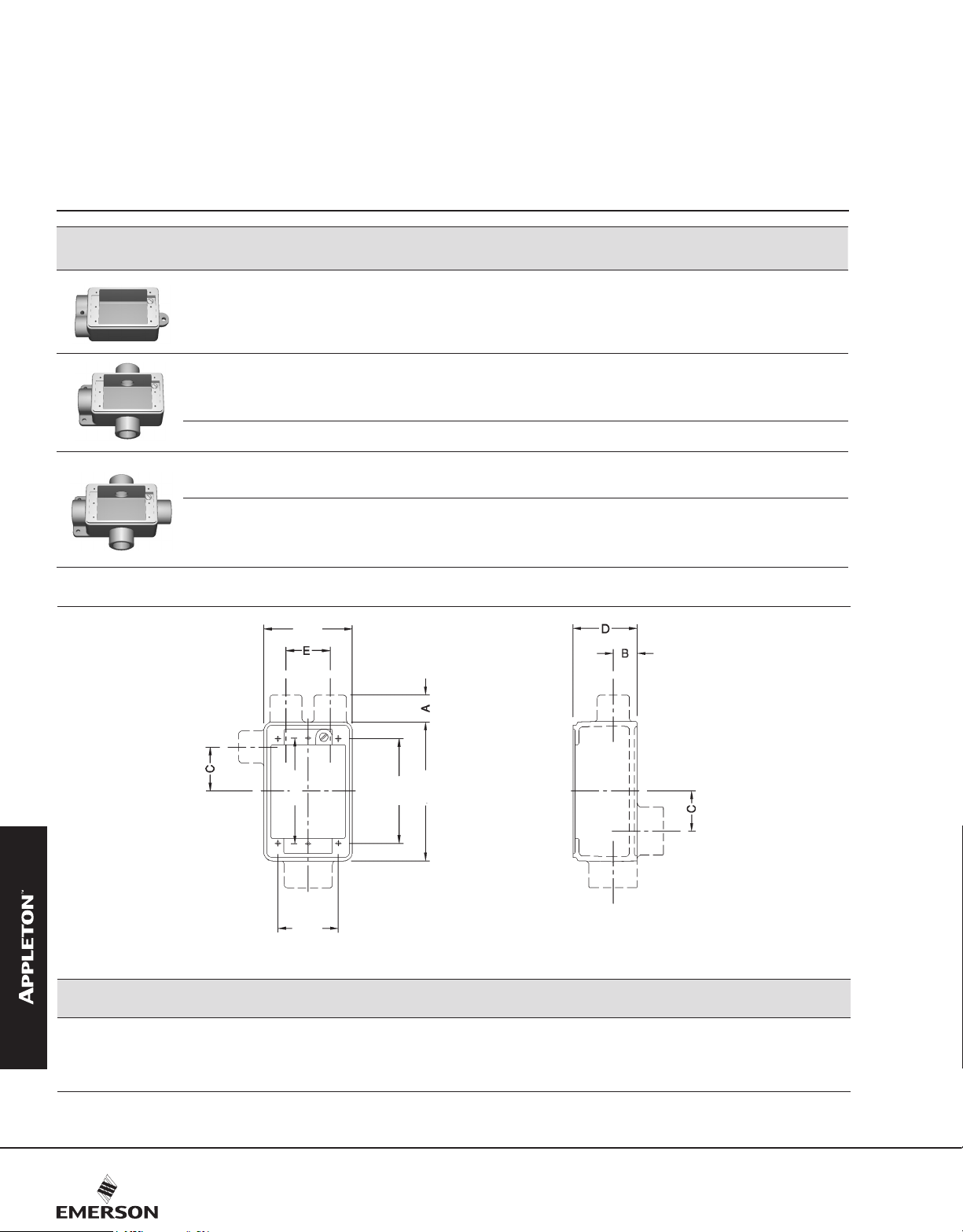
Dimensions in Millimeters (Inches)
Shallow
Shallow
Shallow
Deep
69.9
(2.75)
0.82 (1.80) FSS-1
1.12 (2.46) FST-1
1.25 (2.75) FSX-1
1.41 (3.10) FDX-1
Shallow
Shallow
Shallow
Deep
0.27 (0.60) FSS-1A
0.37 (0.82) FST-1A
0.41 (0.91) FSX-1A
0.47 (1.03) FDX-1A
COMMERCIAL AND INDUSTRIAL FITTINGS: CAST DEVICE BOXES
132
83.3
(3.28)
47.8
(1.88)
82.6
(3.25)
109.5
(4.31)
FS and FD Single Gang Devices
D
Hub Size A B C
1/2 0.3 (0.75) 0.3 (0.63) 0.6 (1.38) 0.9 (2.00) 1.3 (2.75) 0.6 (1.38)
3/4 0.3 (0.75) 0.3 (0.75) 0.6 (1.38) 0.9 (2.00) 1.3 (2.75) 0.6 (1.38)
1 0.4 (0.88) 0.4 (0.88) 0.8 (1.25) 0.9 (2.00) 1.3 (2.75) 0.6 (1.38)
Visit our website at www.emerson.com or contact us at (800) 621-1506.
© November 2020
EFS FD
Page 4
FS and FD Cast Hub Device Boxes
UNILETS™ for use with Threaded Rigid Conduit and IMC.
CEC:
Listed for Ordinary Locations
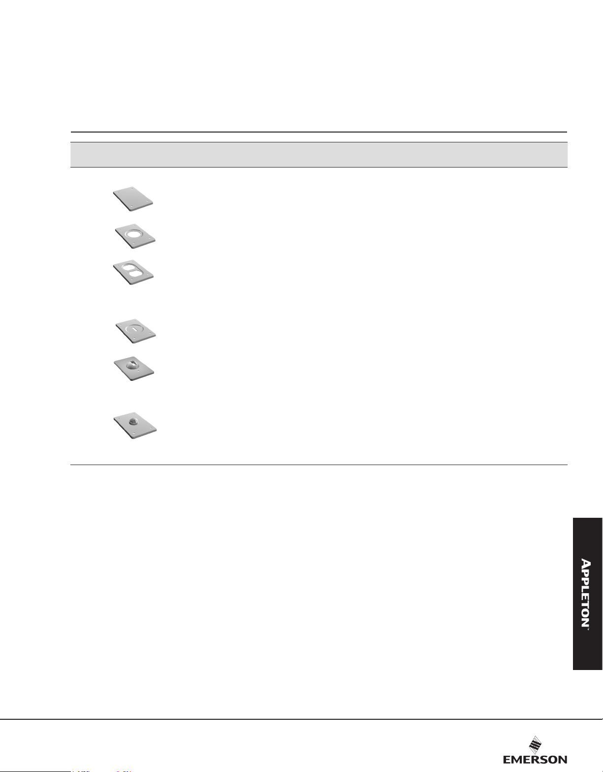
Description
Single Gang Covers — Furnished with stainless steel screws less gasket
Blank Cover, Steel — Zinc Electroplate 5.44 (12.00)
Round Receptacle Cover, Steel — Zinc Electroplate
Hole dia. 1-7/16"
Duplex Receptacle Cover, Steel — Zinc Electroplate 4.54 (10.00)
Round Receptacle Cover, Steel — Zinc Electroplate
Hole dia. 1-5/8"
Tumbler Switch Cover, Steel — Zinc Electroplate 5.44 (12.00)
Tumbler Switch Cover, Steel — Zinc Electroplate 9.98 (22.00)
For pilot lamp
Red Jewel
Amber Jewel
Green Jewel
Opal Jewel
Weight Per 100
kg (lb)
5.44 (12.00)
5.44 (12.00)
11.34 (25.00)
Catalog
Number
FS-4
FS-5
FS-6
FS-8
FS-9
FSK-1TS-G
FSK-1J
FSK-1JA
FSK-1JG
FSK-1JO
COMMERCIAL AND INDUSTRIAL FITTINGS: CAST DEVICE BOXES
Available in Aluminum: Add suffix -A to Catalog Number.
Also for use with multiple gang Unilets with individual cover openings.
Visit our website at www.emerson.com or contact us at (800) 621-1506.
© November 2020
133
Page 5

FS and FD Cast Hub Device Boxes
UNILETS™ for use with Threaded Rigid Conduit and IMC.
NEC/CEC:
Listed for Ordinary Locations
Description
Cast Covers NEMA 3 — Weatherproof — Furnished with gasket and stainless steel screws
Catalog Number
Malleable Iron
Ridge Top
Aluminum
Ridge Top
Receptacle cover with spring cover.
Hole Diameter — 1-7/16”
Rocker type for square handle tumbler or toggle switches FSK-1V FSK-1V-A
For duplex flush receptacle with spring cover FSK-1VDR FSK-1VDR-A
For external operation of tumbler switches with square
handles
Operating type for square handle tumbler or toggle switches FSK-1VS FSK-1VS-A
Blank Cover and Gasket, Malleable Iron, Zinc Electroplate — FS-100G
Gasket — Replacement
Neoprene – for use with weatherproof covers FS-GKR-1N FS-GKR-1N
Cast Covers Dry Locations — Furnished with stainless steel screws less gasket
FSK-1VR —
FSK-1VTS
FSK-1VTSA
COMMERCIAL AND INDUSTRIAL FITTINGS: CAST DEVICE BOXES
134
For standard 2 or 3 wire duplex receptacles FSK-1DR-C —
For round flush receptacles.Hole dia. 1-7/16" FSK-1R-Z —
For square handle toggle switches FSK-1TS-C —
For square handle toggle switches (with protecting guard) FSK-1TSG-C FSK-1TSG-CA
Visit our website at www.emerson.com or contact us at (800) 621-1506.
© November 2020
Page 6

FS and FD Cast Hub Device Boxes
Weatherproof, Raintight and Dust-tight
Covers for Ridge Top Boxes.
NEC/CEC:
Listed for Ordinary Locations
Catalog Number
Receptacles
Receptacle Plug Pole/Wire
Receptacle cover has threaded aluminum cap. Plug has neoprene boot and aluminum fastening ring. Furnished with receptacle, neoprene gasket, stainless steel
screws.
Non-Locking, “U” Shaped Grounding Type — Receptacle takes “U” shaped or round grounding contact plugs
15 Amp, 125V
NEMA 5-15R NEMA 5-15P 2P, 3W FSK5-15 FSK5-15-A FSWP5-15
20 Amp, 125V
Malleable Iron
Ridge Top
Aluminum
Ridge Top
Plug
Locking Grounding Type
NEMA 5-20R NEMA 5-20P 2P, 3W
15 Amp, 250V
NEMA 6-15R NEMA 6-15P 2P, 3W FSK6-15 FSK6-15-A FSWP6-15
20 Amp, 250V
NEMA 6-20R NEMA 6-20P 2P, 3W
15 Amp, 125V
NEMA L5-15R NEMA L5-15P 2P, 3W FSKL5-15 FSWPL5-15
15 Amp, 250V
NEMA L6-15R NEMA L6-15P 2P, 3W FSKL6-15 FSWPL6-15
15 Amp, 277V
NEMA L7-15R NEMA L7-15P 2P, 3W FSKL7-15 FSWPL7-15
FSK5-20 FSK5-20-A
FSK6-20
FSK6-20-A FSWP6-20
FSWP5-20
COMMERCIAL AND INDUSTRIAL FITTINGS: CAST DEVICE BOXES
Also takes FSWP5-15 Plugs.
Also takes FSWP6-15 Plugs.
Visit our website at www.emerson.com or contact us at (800) 621-1506.
© November 2020
135
Page 7

FS and FD Cast Hub Device Boxes
UNILETS™ for use with Threaded Rigid Conduit and IMC. All device boxes have ridge top construction.
CEC:
Listed for Ordinary Locations
Gray Iron Aluminum
Size
1/2
Shallow
3/4 1.18 (2.60) FS-22 0.39 (0.87) FS-22A
1/2
3/4 1.22 (2.70) FD-22 0.41 (0.90) FD-22A
Deep
1 1.27 (2.80) FD-32 Deep 0.42 (0.93) FD-32A
1/2
3/4 1.36 (3.00) FSC-22 0.45 (1.00) FSC-22A
Shallow
1/2
3/4 1.36 (3.00) FDC-22 0.48 (1.06) FDC-22A
Deep
1 1.41 (3.10) FDC-32 0.47 (1.03) FDC-32A
Weight kg (lb) Catalog Number Weight kg (lb) Catalog Number
1.22 (2.70) FS-12
1.22 (2.70) FD-12
1.36 (3.00) FSC-12
1.32 (2.90) FDC-12
Shallow
Shallow
Shallow
Deep
0.41 (0.90) FS-12A
0.41 (0.90) FD-12A
0.45 (1.00) FSC-12A
0.44 (0.97) FDC-12A
Dimensions in Millimeters (Inches)
COMMERCIAL AND INDUSTRIAL FITTINGS: CAST DEVICE BOXES
Hub Size A B C FS FD E
1/2 19.1 (0.75) 16.0 (0.63) 35.1 (1.38) 50.8 (2.00) 69.9 (2.75) 58.7 (2.31)
3/4 19.1 (0.75) 19.1 (0.75) 35.1 (1.38) 50.8 (2.00) 69.9 (2.75) 58.7 (2.31)
1 22.4 (0.88) 22.4 (0.88) 31.8 (1.25) 50.8 (2.00) 69.9 (2.75) 58.7 (2.31)
1/2 - 3/4 Shallow 1.22 (2.70)
117.6
(4.63)
95.3
(3.75)
83.3
(3.28)
47.8
(1.81)
82.6
(3.25)
109.5
(4.31)
FS and FD Two-Gang Devices
Dimensions in Millimeters (Inches)
FSD-212
Shallow 0.41 (0.90)
D
FSD-212A
Hubs at top of illustration are 1/2”.
136
Visit our website at www.emerson.com or contact us at (800) 621-1506.
© November 2020
Page 8

FS and FD Cast Hub Device Boxes
UNILETS™ for use with Threaded Rigid Conduit and IMC.
CEC:
Listed for Ordinary Locations
Two Gang Covers
Description
Blank Cover, Steel – Zinc Electroplate 9.07 (20.00)
Round Receptacle Cover, Steel – Zinc Electroplate
Hole dia. 1-7/16"
Duplex Receptacle Cover, Steel-Zinc Electroplate 6.80 (15.00)
Tumbler Switch Cover, Steel –Zinc Electroplate 9.07 (20.00)
Combination Duplex Receptacle and Tumbler Switch
Cover, Steel - Zinc Electroplate
Weight Per 100
kg (lb) Catalog Number
8.16 (18.00)
6.80 (15.00)
FS-42
FS-52
FS-62
FS-92
FS-69
COMMERCIAL AND INDUSTRIAL FITTINGS: CAST DEVICE BOXES
Combination Duplex Receptacle and Single Receptacle,
Steel - Zinc Electroplate
Weatherproof Covers
Blank Cover, Gray Iron 25.40 (56.00)
Gasket — Replacement
Neoprene - for use with 2-gang cast covers above — FS-GKR-2N
Available in Aluminum: Add suffix -A to catalog number.
Visit our website at www.emerson.com or contact us at (800) 621-1506.
© November 2020
6.80 (15.00)
FS-65
FS-200G
137
Page 9

FS and FD Cast Hub Device Boxes
UNILETS™ for use with Threaded Rigid Conduit and IMC. All device boxes have ridge top construction.
CEC:
Listed for Ordinary Locations
Three Gang Covers
Weatherproof Covers
Description
Duplex Receptacle Cover, Steel – Zinc Electroplate 10.43 (23.00)
Tumbler Switch, Steel –Zinc Electroplate 11.34 (25.00)
Blank Cover, Gray Iron 54.43 (120.00)
Weight Per 100
kg (lb) Catalog Number
FS-63
FS-93
FS-300G
COMMERCIAL AND INDUSTRIAL FITTINGS: CAST DEVICE BOXES
Available in Aluminum: Add suffix -A to catalog number.
138
Visit our website at www.emerson.com or contact us at (800) 621-1506.
© November 2020
Page 10

FD0 Single and Multiple Gang Cast Device Boxes
UNILETS™ for use with Threaded Rigid Conduit and IMC. All device boxes have ridge top construction.
CEC:
Listed for Ordinary Locations
Features
• Thick wall on all four sides.
• Drill and tap anywhere on sidewalls.
• Ground screw at top of box for easy access.
• Two exterior mounting lugs.
• Fits standard sheet metal device covers with four mounting
holes.
• Weatherproof when used with gasketed cast weatherproof
device covers.
Standard Finishes
• Malleable iron: zinc electroplate
• Aluminum: natural
Reference Data
• When ordering drilled and tapped openings or brazed hubs
for blank bodies, refer to FD0 Cast Device Boxes Drilling and
Tapping Information page.
Standard Materials
• Malleable iron or copperfree (4/10 of 1% max.) aluminum
Catalog Number
Description
FD0 Unilets with Lugs: FD depth 2-19/32" — Maximum hub size 1-1/2" threaded, and 1-1/4" no-thread or union.
Single-Gang
Two-Gang FD0-2 FD0-2A
Gray Iron Aluminum
FD0-1 FD0-1A
COMMERCIAL AND INDUSTRIAL FITTINGS: CAST DEVICE BOXES
Three-Gang FD0-3 FD0-3A
Four-Gang
FD0-4 FD0-4A
Visit our website at www.emerson.com or contact us at (800) 621-1506.
© November 2020
139
Page 11

FD0 Single and Multiple Gang Cast Device Boxes
UNILETS™ for use with Threaded Rigid Conduit and IMC. All device boxes have ridge top construction.
CEC:
Listed for Ordinary Locations
Dimensions in Millimeters (Inches)
Spacing for Multi-Gang Boxes
3.3
(0.13)
R 7.1
(0.28)
22.6/
0.89
3.3
(0.13)
Ø 7.9
(0.31)
46.0
(1.81)
46.0
(1.81)
12.7
(0.50)
4.1
(0.16)
4.1
(0.16)
1.5
(0.06)
73.2
(2.88)
61.2
(2.41)
#10-24 UNC-2B 1 Hole
R 6.4
(0.25)
R 6.4
(0.25)
73.2 (2.88)
83.3 (3.28)
96.8 (3.81)
122.2 (4.81)
109.5 (4.31)
3.3
(0.13)
#6-32 UNC-2B “F” Holes
3.3
(0.13)
No. of Gangs A B C
1 82.60 (3.25) 69.90 (2.75) 58.67 (2.31) 47.80 (1.88) 44.50 (1.75) 152.40 (6.00)
2 130.30 (5.13) 117.60 (4.63) 106.40 (4.19) 95.30 (3.75) 68.30 (2.69) 203.20 (8.00)
3 177.80 (7.00) 165.10 (6.50) 154.00 (6.06) 143.00 (5.63) 92.20 (3.63) 254.00 (10.00)
4 225.60 (8.88) 212.90 (8.38) 201.70 (7.94) 190.50 (7.50) 115.80 (4.56) 304.80 (12.00)
COMMERCIAL AND INDUSTRIAL FITTINGS: CAST DEVICE BOXES
FDO Unilets
82.6 (3.25)
65.0 (2.56)
3.3
3.3
(0.13)
(0.13)
D
E F
3.3
(0.13)
140
Visit our website at www.emerson.com or contact us at (800) 621-1506.
© November 2020
Page 12

FD0 Single and Multiple Gang Cast Device Boxes
Malleable Iron, Aluminum
UNILETS™ for use with Threaded Rigid Conduit and IMC. All device boxes have ridge top construction.
CEC:
Listed for Ordinary Locations
Hub Information
Listed below are the various types of brazed hubs which may be
used with the FD0 boxes. Threaded, no-thread and union hubs may
be brazed at any desired location.
It is possible to place more than five hubs on the top and bottom of
three and four-gang Unilets.
Look at the chart below for the maximum hub diameter and the
minimum hub spacing distance. This chart, together with the Unilet
dimensions will enable you to figure the maximum number of hubs
which may be used.
The hubs will be symmetrically placed about the axis of the Unilets
unless exact dimensions are specified on the order.
Maximum Hub Size
Maximum Hub
Diameter
Maximum Distance
Between Conduit
Centers
Size
FS 1 3/4 3/4 3/4
FD 1-1/2 1-1/4 1-1/4 1-1/4
1/2 1-1/8 1-1/2 1-1/8 1-1/2
3/4 1-3/8 1-25/32 1-3/8 1-25/32
1 1-9/16 2-1/32 1-9/16 2-1/32
1-1/4 1-15/16 2-25/32 1-15/16 2-25/32
1-1/2 2-3/16 — — —
1/2 1-1/4 1-9/16 1-1/4 1-9/16
3/4 1-1/2 1-27/32 1-1/2 1-27/32
1 1-3/4 2-3/32 1-3/4 2-3/32
1-1/4 2-1/8 2-29/32 2-1/8 2-29/32
1-1/2 2-3/8 — — —
Threaded for
Rigid Conduit
No Thread for
Rigid Conduit
COMMERCIAL AND INDUSTRIAL FITTINGS: CAST DEVICE BOXES
No Thread for
Electrical Metallic
Tubing Union
Visit our website at www.emerson.com or contact us at (800) 621-1506.
© November 2020
141
Page 13

FD0 Cast Device Boxes Drilling and Tapping Information
Malleable Iron, Aluminum
UNILETS™ for use with Threaded Rigid Conduit and IMC. All device boxes have ridge top construction.
CEC:
Listed for Ordinary Locations
Ordering Data
To determine the customized FD0 box catalog number with
drilled and tapped entries or hubs, the following information
should be shown:
1. FD0 box catalog number.
2. Sketch number of entry arrangement selected from
illustrations below.
3. Entry symbols taken from the table right. Start from the left on
the top of the Unilet and continue in rotation clockwise around
its body. Where no entry is required, the symbol X should be
inserted. The three various divisions of the catalog number
should be separated by dashes.
Symbol Table
Ordering Example:
The box selected is a FD04 and the entry arrangement is sketch
number 12. Entry A, B and C are to be 1/2" drilled and tapped
for rigid conduit; D is to be a 1" hub and there is no entry at
location E. The catalog number will be as follows
FD04-12-111CX.
Single, Two, Three and Four-Gang — Front view and oriented as mounted
ABTOP
SIDES
BOTTOM
1 2 3 4 5 6 7
A
A
C
B
A
A
B
A B
C
A
B
C
A
B
Hub Size
(Inches)
Blank X X
1/2 1 A
3/4 2 B
1 3 C
1-1/4 4 D
1-1/2 5 E
2 6 F
A B
E
D
A B
Brazed Threaded Hub
C
C
Symbol
A BCD
F
E
A BCD
Brazed Union
Hub Symbol
ABCDE
A BCD
G
F
E
D B
COMMERCIAL AND INDUSTRIAL FITTINGS: CAST DEVICE BOXES
B
A
K
J
H F
142
C B
C
8 9 10 11 12 13 14
A
C
16 17 18 19 20 21 22
B
C
D
E
G
23 24 25 26 27 28 29
A
C
A
B
F E
B
C D
C
A
D
C
A B
C D
K E
GHJ
D
A
B
B
F
E D
A B
C D
M
L
F
HJK
C
C
E
F
G
E D
A
B
H
G
J
F E
A
EBCD
G F
Visit our website at www.emerson.com or contact us at (800) 621-1506.
F E
C
D
A EBCD
M F
L GK
A B
F
E
J H
G F
C
D
A B
H D
G
A B
O F
N
L
M H
© November 2020
C
F
E
CDE
K
J
G
 Loading...