

Page 1
Instruction Manual
D104197X012
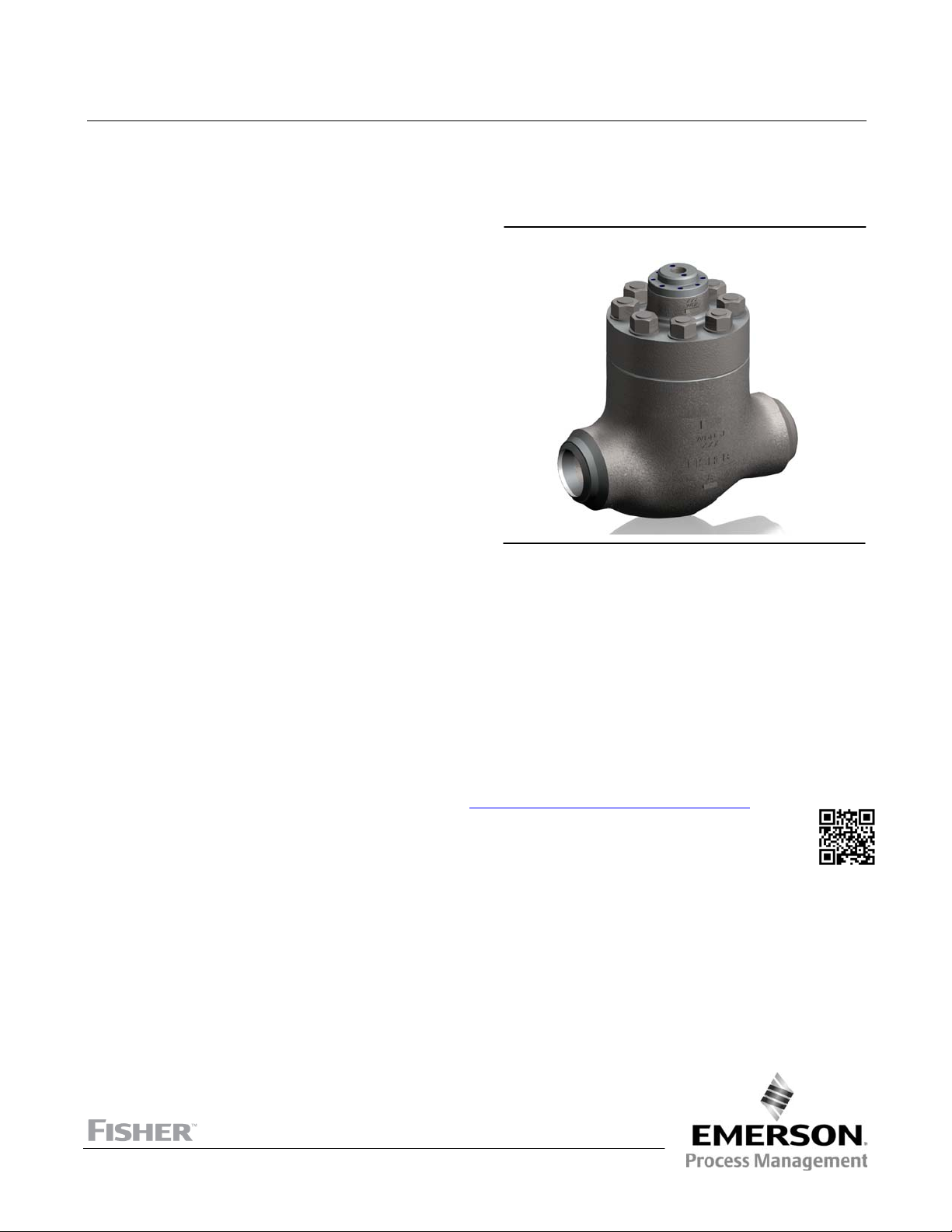
Fisher™ NPS 8 CHP Control Valve
NPS 8 CHP Valve
September 2016
Contents
Introduction 1.................................
Scope of Manual 1.............................
Description 2.................................
Specifications 2...............................
Installation 3..................................
Lifting Guidelines 3.............................
Maintenance 4.................................
Packing Maintenance 6.........................
Adding Packing Rings 7.....................
Replacing Packing 7........................
Trim Removal 10..............................
Valve Plug Maintenance 10.....................
Lapping Seats 11..............................
Trim Replacement 11..........................
Parts Ordering 12...............................
Parts List 13...................................
Introduction
Scope of Manual
Figure 1. Fisher CHP NPS 8 Control Valve
X1365
This instruction manual includes installation, maintenance, and parts information for the Fisher CHP control valve.
Refer to separate manuals for instructions covering the actuator, positioner, and accessories.
Do not install, operate, or maintain CHP valves without being fully trained and qualified in valve, actuator, and
accessory installation, operation, and maintenance. To avoid personal injury or property damage, it is important to
carefully read, understand, and follow all the contents of this manual, including all safety cautions and warnings. If you
have any questions about these instructions, contact your Emerson Process Management sales office
proceeding.
before
www.Fisher.com
Page 2

NPS 8 CHP Valve
September 2016
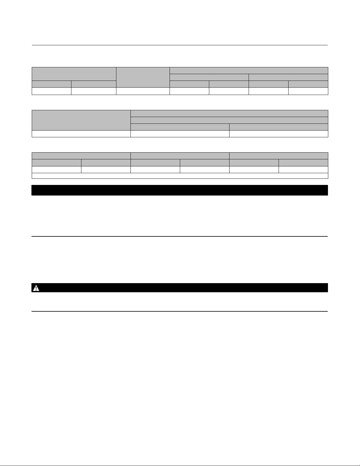
Table 1. Specifications
Instruction Manual
D104197X012
Size/Pressure Class/Body Materials
NPS 8 / CL2500 / WCC, WC9
Maximum Inlet Pressure and Temperature
Consistent with ASME B16.34 except CHPT PEEK
anti‐extrusion seal ring construction. Maximum
temperature limit is 380_C (716_F).
End Connection Style
Buttweld Ends : All buttwelding end schedules per
ASME B16.25
Bonnet and Body‐to‐Bonnet Bolting
Plain Bonnet: 5 inch H Yoke Boss
Studs: Steel A 193‐B7/NCF2
Nuts: Steel A 194‐2H/NCF2
1. The pressure/temperature limits in this manual and any applicable standard or code limitation for valve should not be exceeded.
2. For Boiler feedwater application, proper use of a block valve during closing of the control valve is recommended to minimize control valve trim damage.
(1)
Flow Coefficient
Maximum Cv: 514 Km: 0.74 Fl: 0.86
Modified Equal Percentage
Flow Direction
Flow down and up
Stem Diameter
1‐1/4 inch VSC (Valve Stem Connection)
Shutoff Classification per ANSI/FCI 70‐2 and IEC
60534-4
CHPT: Class IV (standard), Class V (optional)
CHPD: Class V with Bore seal (standard)
Weight
Estimated Valve Body and Bonnet Assemblies 810 kg
Please consult Singapore SD&S for any queries
(2)
Description
The CHP globe valve (figure 1) has a metal seat, cage guiding, quick change trim, and push-down-to-close valve plug
action. The valve uses a balanced valve plug. To provide a seal between the cage and a balanced valve plug, the
balanced valve plug uses a PEEK (Poly Ether Ether Ketone) anti-extrusion ring with a pressure-assisted spring-loaded
seal ring.
Educational Services
For information on available courses for the Fisher CHP valve, as well as a variety of other products, contact:
Emerson Process Management
Educational Services - Registration
Phone: 1-641-754-3771 or 1-800-338-8158
E-mail: education@emerson.com
http://www.emersonprocess.com/education
Specifications
Specifications for the CHP valves are shown in table 1.
2
Page 3

Instruction Manual
D104197X012
NPS 8 CHP Valve
September 2016
Installation
WARNING
Always wear protective gloves, clothing, and eyewear when performing any installation operations to avoid personal
injury.
Personal injury or property damage caused by sudden release of pressure may result if the valve assembly is installed
where service conditions could exceed the limits given in table 1 or on the appropriate nameplates. To avoid such injury or
damage, provide a relief valve for over-pressure protection as required by government or accepted industry codes and
good engineering practices.
Check with your process or safety engineer for any additional measures that must be taken to protect against process
media.
If installing into an existing application, also refer to the WARNING at the beginning of the Maintenance section in this
instruction manual.
CAUTION
When ordered, the valve configuration and construction materials were selected to meet particular pressure, temperature,
pressure drop, and controlled fluid conditions. Because some body/trim material combinations are limited in their pressure
drop and temperature ranges, do not apply any other conditions to the valve without first checking with your Emerson
Process Management sales office.
1. Before installing the valve, inspect it to ensure that the valve body cavity is free of foreign material.
2. Clean out all pipelines to remove scale, welding slag, and other foreign materials before installing the valve.
3. Flow through the valve must be in the direction indicated by the flow arrow, which is attached to the valve body.
4. Use accepted piping practices when installing the valve in the pipeline.
5. Install a three‐valve bypass around the valve if continuous operation is required during maintenance.
6. If the actuator and valve body are shipped separately, refer to the actuator mounting procedure in the appropriate
actuator instruction manual.
7. If the valve body was shipped without packing installed in the packing box, install the packing before putting the
valve body into service. Refer to instructions given in the Packing Maintenance procedure.
WARNING
Personal injury could result from packing leakage. Valve packing was tightened prior to shipment; however, the packing
might require some readjustment to meet specific service conditions. Check with your process or safety engineer for any
additional measures that must be taken to protect against process media.
Lifting Guidelines
CAUTION
Care must be taken when lifting the valve/actuator assembly to ensure the accessories and tubing are not damaged in the
process. The entire assembly with accessories weighs approximately 1500 kg (3310 lb). Make sure to use appropriate
lifting straps/hoist rings capable of lifting this weight.
3
Page 4

NPS 8 CHP Valve
September 2016
Instruction Manual
D104197X012
WARNING
Avoid personal injury or damage caused by uncontrolled movement or dropping of the assembly valve:
D Swivel hoist rings are sized to lift only the valve and actuator. Do not attached piping or other structures to the valve
and actuator assembly when lifting swivel hoist rings.
D Take appropriate precautions to avoid unbalanced loading which may result in sudden swinging or movement of the
assembled unit, including additional lifting and/or support methods when necessary.
D Do not use eyebolts when lifting the valve or valve actuator assembly due to variable loading angles inherent to valve
maintenance and installation.
D Failure to utilize safe lifting practices may result in equipment damage and/or personal injury.
Lifting Valve/Actuator Assembly
To lift the assembly, insert swivel hoist rings (recommend ¾ -10 UNC) into the four lifting hole locations on the outside
diameter of the bonnet flange. The lifting point must be high enough away from the top of the accessory mountings
to prevent damage to accessories or piping. When lifting the valve and actuator assembly, a strap around the actuator
may be required to ensure lifting stability. Lifting the assembly without using the hoist rings is not preferred.
Lifting Bonnet Only
To lift the bonnet, insert swivel hoist rings (recommend ¾ -10 UNC) into the four lifting hole locations on the outside
diameter of the bonnet flange. Use proper length, or adjustable chains to ensure the bonnet and valve body mating
surfaces remain parallel when hoisted.
Maintenance
Refer to figure 4.
Valve parts are subject to normal wear and must be inspected and replaced as necessary. Inspection and maintenance
frequency depends on the severity of service conditions. This section includes instructions for packing maintenance
and trim maintenance. All maintenance operations may be performed with the valve in the line.
WARNING
Avoid personal injury or damage to property from sudden release of pressure or uncontrolled process fluid. Before starting
disassembly:
D Do not remove the actuator from the valve while the valve is still pressurized.
D Always wear protective gloves, clothing, and eyewear when performing any maintenance operations to avoid personal
injury.
D Disconnect any operating lines providing air pressure, electric power, or a control signal to the actuator. Be sure the
actuator cannot suddenly open or close the valve.
D Use bypass valves or completely shut off the process to isolate the valve from process pressure. Relieve process pressure
on both sides of the valve. Drain the process media from both sides of the valve.
D Vent the power actuator loading pressure and relieve any actuator spring precompression.
D Use lock‐out procedures to be sure that the above measures stay in effect while you work on the equipment.
D The valve packing box may contain process fluids that are pressurized, even when the valve has been removed from the
pipeline. Process fluids may spray out under pressure when removing the packing hardware or packing rings, or when
loosening the packing box pipe plug.
D Check with your process or safety engineer for any additional measures that must be taken to protect against process
media.
4
Page 5

Instruction Manual
D104197X012
NPS 8 CHP Valve
September 2016
Figure 2. Packing Arrangements
UPPER WIPER (KEY 12)
PACKING FOLLOWER
(KEY 13)
FEMALE ADAPTOR
(KEY 32)
V‐RING (KEY 7)
MALE ADAPTOR
(KEY 31)
WASHER (KEY 10)
SPRING (KEY 8)
PACKING BOX RING
(KEY 11)
12A8160‐A
PTFE V‐RING
SINGLE PACKING
12A7839‐A
Sht 1
PTFE V‐RING
DOUBLE PACKING
NOTES:
1
0.102 mm (0.004 INCH) THICK SACRIFICIAL ZINC WASHERS.
USE ONLY ONE BELOW EACH GRAPHITE LAMINATE RING.
C0634‐1
LOWER WIPER
(KEY 30)
UPPER WIPER (KEY 12)
PACKING FOLLOWER
(KEY 13)
FEMALE ADAPTOR
(KEY 32)
V‐RING (KEY 7)
MALE ADAPTOR
(KEY 31)
LANTERN RING
(KEY 8)
PACKING BOX RING
(KEY 11)
LOWER WIPER
(KEY 30)
PACKING ARRANGEMENTS FOR 31.8 mm (1‐1/4 INCH) VALVE STEMS
PACKING FOLLOWER
(KEY 13)
GRAPHITE LAMINATE
KEY 6
1
14A3412‐B
PACKING RING (KEY 7)
2
GRAPHITE FILAMENT
PACKING RING (KEY 9)
3
LANTERN RING
(KEY 8)
PACKING BOX RING
(KEY 11)
GRAPHITE LAMINATE AND FILAMENT
SINGLE PACKING
PACKING FOLLOWER
(KEY 13)
GRAPHITE LAMINATE
KEY 6
1
1
14A3414‐B
PACKING RING (KEY 7)
2
GRAPHITE FILAMENT
PACKING RING (KEY 9)
3
LANTERN RING
(KEY 8)
PACKING BOX RING
(KEY 11)
GRAPHITE LAMINATE AND FILAMENT
DOUBLE PACKING
2
HAS THE APPEARANCE OF FLAT WASHERS PRESSED TOGETHER.
3
HAS THE APPEARANCE OF A WOVEN OR BRAIDED RING.
13A0112‐A
GRAPHITE/COMPOSITION
DOUBLE PACKING
12A8163‐A
PTFE/COMPOSITION
DOUBLE PACKING
UPPER WIPER (KEY 12)
PACKING FOLLOWER
(KEY 13)
PACKING RING
(KEY 7)
PACKING RING
(KEY 7)
LANTERN RING
(KEY 8)
PACKING BOX RING
(KEY 11)
UPPER WIPER (KEY 12)
PACKING FOLLOWER
(KEY 13)
PACKING RING
(KEY 7)
LANTERN RING
(KEY 8)
PACKING BOX RING
(KEY 11)
5
Page 6
NPS 8 CHP Valve
September 2016
Instruction Manual
Table 2. CL2500 Recommended Torque for Packing Flange Nuts (non live‐loaded)
VALVE STEM
DIAMETER
mm Inches Min Max Min Max
31.8 1‐1/4 CL2500 81 122 60 90
PRESSURE RATING
NSm lbfSft
TORQUE
Table 3. Torque for Body‐to‐Bonnet Bolting Using Anti‐Seize Lubricant
BOLT TORQUES
VALVE RATING
NSm lbfSft
CL2500 4240 3130
SA193‐B7, B16
D104197X012
Table 4. Valve Stem Connection Torque and Hole Size for Pin
VALVE STEM DIAMETER TORQUE, MINIMUM TO MAXIMUM HOLE SIZE
mm Inches NSm LbfSft mm Inch
31.8 1‐1/4 735-993 544-736 6.38-6.45 0.251-0.254
1. VSC (Valve Stem Connection) size is 1 1/4-inch.
(1)
CAUTION
The CHP valve uses spiral‐wound gaskets which are crushed to provide their seal. A spiral‐wound gasket should never be
reused. Whenever a gasket seal is disturbed by removing or shifting gasketed parts, a new gasket must be installed upon
reassembly. This is necessary to ensure a good gasket seal, since the used gasket will not seal properly.
The spiral‐wound gaskets are of special design. Failure to use genuine Fisher replacement parts may result in valve damage
and/or failure.
Packing Maintenance
Key numbers refer to figure 2 for PTFE V‐ring packing and graphite ribbon/filament, unless otherwise indicated.
WARNING
To avoid personal injury or equipment damage resulting from packing leakage, inspect the valve plug stem and packing
box wall for nicks or scratches while performing the following procedures. Use care to avoid damaging these surfaces.
For spring‐loaded single PTFE V‐ring packing, the spring maintains a sealing force on the packing. If leakage is noted
around the packing follower, check to be sure the shoulder on the packing follower is touching the bonnet. If the
shoulder is not touching the bonnet, tighten the packing flange nuts until the shoulder is against the bonnet. If
leakage cannot be stopped in this manner, proceed to the Replacing Packing procedure.
If there is undesirable packing leakage with other than spring‐loaded PTFE V‐ring packing, first try to limit the leakage
and establish a stem seal by tightening the packing flange nuts to at least the minimum recommended torque in table
2. However, do not exceed the maximum recommended torque in table 2 or excessive friction may result. If leakage
continues, replace the packing by following the numbered steps presented in the Replacing Packing procedure.
If the packing is relatively new and tight on the valve plug stem, and if tightening the packing flange nuts does not stop
the leakage, it is possible that the stem is worn or nicked so that a seal cannot be made. The surface finish of a new
stem is critical for making a good packing seal. If the leakage comes from the outside diameter of the packing, it is
possible that the leakage is caused by nicks or scratches around the packing box wall. While replacing the packing
according to the Replacing Packing procedure, inspect the valve plug stem and packing box wall for nicks or scratches.
6
Page 7

Instruction Manual
D104197X012
NPS 8 CHP Valve
September 2016
Adding Packing Rings
WARNING
Refer to the WARNING at the beginning of the Maintenance section in this instruction manual.
To avoid personal injury or equipment damage resulting from packing leakage, inspect the valve plug stem and packing
box wall for nicks or scratches while performing the following procedures.
Use care to avoid damaging these surfaces.
Key numbers referred to in this procedure are shown in figure 4, unless otherwise indicated.
When using packing with a lantern ring it may be possible to add packing rings above the lantern ring as a temporary
measure without removing the actuator from the valve body.
1. Isolate the control valve from the line pressure, release pressure from both sides of the valve body, and drain the
process media from both sides of the valve. If using a power actuator, also shut‐off all pressure lines to the power
actuator, release all pressure from the actuator. Use lock‐out procedures to be sure that the above measures stay in
effect while you work on the equipment.
2. Remove the packing flange nuts and lift the packing flange, upper wiper, and packing follower away from the valve
body.
3. It may be possible to dig out the old packing rings on top of the lantern ring, but use care to avoid scratching the
valve plug stem or packing box wall. Clean all metal parts to remove particles that would prevent the packing from
sealing.
4. Remove the stem connector and slip the packing rings over the end of the valve plug stem.
5. Reassemble the packing follower, upper wiper, packing flange, and packing flange nuts.
6. Reconnect the body‐actuator stem connection according to the appropriate actuator instruction manual.
7. Tighten the packing flange nuts only far enough to stop leakage under operating conditions. Check for leakage
around the packing follower when the valve is being put into service. Retighten the packing flange nuts as required
(see table 2).
Replacing Packing
WARNING
Refer to the WARNING at the beginning of the Maintenance section in this instruction manual.
To avoid personal injury or equipment damage resulting from packing leakage, inspect the valve plug stem and packing
box wall for nicks or scratches while performing the following procedures.
Use care to avoid damaging these surfaces.
Key numbers referred to in this procedure are shown in figure 4, unless otherwise indicated.
1. Isolate the control valve from the line pressure, release pressure from both sides of the valve body, and drain the
process media from both sides of the valve. If using a power actuator, also shut‐off all pressure lines to the power
actuator, release all pressure from the actuator. Use lock‐out procedures to be sure that the above measures stay in
effect while you work on the equipment.
2. Remove the cap screws in the stem connector, and separate the two halves of the stem connector. Then exhaust all
actuator pressure, if any was applied, and disconnect the actuator supply and any leakoff piping.
3. Remove the hex nuts (key 11), and remove the actuator from the bonnet (key 14).
4. Loosen the packing flange nuts so that the packing is not tight on the valve plug stem (key 4). Remove the stem
locknuts from the valve plug stem threads.
7
Page 8

NPS 8 CHP Valve
September 2016
Instruction Manual
D104197X012
CAUTION
When lifting the bonnet (key 14), be sure that the valve plug and stem assembly (keys 3 and 4) remains on the seat ring
(key 7). This avoids damage to the seating surfaces as a result of the assembly dropping from the bonnet after being lifted
part way out. The parts are also easier to handle separately. Use care to avoid damaging gasket sealing surfaces.
WARNING
To avoid personal injury or property damage caused by uncontrolled movement of the bonnet, loosen the bonnet by
following the instructions in the next step. Do not remove a stuck bonnet by pulling on it with equipment that can stretch
or store energy in any other manner. The sudden release of stored energy can cause uncontrolled movement of the bonnet.
If the cage sticks to the bonnet, proceed carefully with bonnet removal and support the cage so that it will not fall
unexpectedly from the bonnet.
Note
The following step also provides additional assurance that the valve body fluid pressure has been relieved.
5. Hex nuts (key 12) attach the bonnet to the valve body. Loosen these nuts approximately 3 mm (1/8 inch). Then
loosen the body‐to‐bonnet gasketed joint by either rocking the bonnet or prying between the bonnet and valve
body. Work the prying tool around the bonnet until the bonnet loosens. If no fluid leaks from the joint, proceed to
the next step. If fluid leaks from the joint, the process pressure was not relieved from the valve as noted in the
Warning at the beginning of the Maintenance section in this manual.
6. Unscrew the hex nuts (key 12) and carefully lift the bonnet off the valve stem. If the valve plug and stem assembly
starts to lift with the bonnet, use a brass or lead hammer on the end of the stem and tap it back down. Set the
bonnet on a cardboard or wooden surface to prevent damage to the bonnet gasket surface.
7. Remove the valve plug (key 3), bonnet gasket (key 15) and three cage gaskets (key 16), seat ring (key 2), and the
seat ring gasket (key 17).
CAUTION
Inspect the seat ring, cage, bonnet, and body gasket surfaces. These surfaces must be in good condition, with all foreign
material removed. Small burrs less than approximately 0.076 mm (0.003 inch) in height (the thickness of a human hair) can
be ignored. Scratches or burrs that run across the serrations are not permitted under any conditions, as they will prevent
the gaskets from sealing properly.
8. Clean all gasket surfaces with a good wire brush. Clean in the same direction as the surface serrations, not across
them.
9. Cover the opening in the valve body to protect the gasket surface and to prevent foreign material from getting into
the valve body cavity.
10. Remove the packing flange nuts, packing flange, upper wiper, and packing follower. Carefully push out all the
remaining packing parts from the valve side of the bonnet using a rounded rod or other tool that will not scratch the
packing box wall.
11. Clean the packing box and the following metal packing parts: packing follower, packing box ring, spring or lantern
ring, and, for single arrangements of PTFE V‐ring packing only, special washer.
12. Inspect the valve stem threads for any sharp edges that might cut the packing. A whetstone or emery cloth may be
used to smooth the threads if necessary.
13. Remove the protective covering from the valve body cavity, and install the seat ring and cage using a new seat ring
gasket (key 17), bonnet gasket (key 15) and three cage gaskets (key 16). Install the plug, then slide the bonnet over
the stem and onto the studs (key 11).
8
Page 9
Instruction Manual
D104197X012
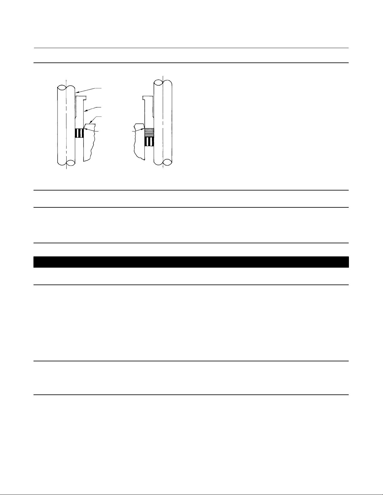
Figure 3. Installing Graphite Ribbon/Filament Packing Rings One at a Time
VALVE STEM
PACKING
FOLLOWER
BONNET
TOP OF
PACKING RING
EVEN WITH
BOTTOM OF
ENTRANCE
CHAMFER
NPS 8 CHP Valve
September 2016
INSTALLING
FIRST PACKING RING
A2207‐2
INSTALLING
SECOND PACKING RING
Note
The prelubricated hex nuts (key 12) referred to in step 14 can be identified by a black film coating on the nut threads.
The proper bolting procedures in step 14 include ‐‐ but are not limited to ‐‐ ensuring that the bonnet stud threads are clean, and
that the hex nuts are evenly tightened to the specified torque values.
CAUTION
Failure to comply with good bonnet‐to‐body bolting practices and the torque values shown in table 3 may result in damage
to the valve. Cheater bars or slug wrenches should not be used for this procedure. Hot torquing is not recommended.
14. Lubricate the stud threads and the faces of the hex nuts (key 12) with anti‐seize lubricant (not necessary if new
factory prelubricated hex nuts are used). Install the hex nuts and tighten them finger‐tight. Stroke the valve several
times to center the trim. Torque the nuts in a crisscross pattern to no more than 1/4 of the nominal torque value
specified in table 3.
When all nuts are tightened to that torque value, increase the torque by 1/4 of the specified nominal torque and
repeat the crisscross pattern. Repeat this procedure until all nuts are tightened to the specified nominal value. Apply
the final torque value again and, if any nut still turns, tighten every nut again.
Note
When installing packing rings, prevent entrapping air between the rings. Add the rings one at a time without forcing them below
the chamfer of the packing box entrance chamber. As each successive ring is added, the stack should not be pushed down more
than the thickness of the added ring (figure 3).
15. Install new packing and the metal packing box parts according to the appropriate arrangement in figure 2. If
desired, packing parts may be pre‐lubricated with a silicon base grease for easier installation. Slip a smooth‐edged
pipe over the valve stem, and gently tap each soft packing part into the packing box, being sure that air is not
trapped between adjacent soft parts.
16. Slide the packing follower, wiper, and packing flange into position. Lubricate the packing flange studs and the faces
of the packing flange nuts. Install the packing flange nuts.
9
Page 10

NPS 8 CHP Valve
September 2016
For the spring‐loaded PTFE V‐ring packing shown in figure 2, tighten the packing flange nuts until the shoulder on the
packing follower contacts the bonnet.
For graphite packing, tighten the packing flange nuts to the maximum recommended torque shown in table 2. Then,
loosen the packing flange nuts, and retighten them to the recommended minimum torque shown in table 2.
For other packing types, tighten the packing flange nuts alternately in small equal increments until one of the nuts
reaches the minimum recommended torque shown in table 2. Then, tighten the remaining flange nuts until the
packing flange is level and at a 90‐degree angle to the valve stem.
17. Mount the actuator on the valve body assembly, and reconnect the actuator and valve plug stems according to the
procedures in the appropriate actuator instruction manual.
Instruction Manual
D104197X012
Trim Removal
Note
Avoid personal injury by supporting the valve properly while removing the trim or while servicing the trim or internal body.
Key numbers referenced in this procedure are shown in figure 4, except where indicated.
1. Remove the actuator and bonnet by following steps 1 through 6 of the replacing packing procedure. Observe all
warnings and cautions in that procedure.
2. Lift the valve stem and attached valve plug out of the valve body. If the valve plug is to be reused, tape or otherwise
protect the valve plug stem and the valve plug seating surface to prevent scratches.
3. Lift out the cage (key 2) and the bonnet gasket (key 15) and three cage gaskets (key 16).
4. Remove the seat ring (key 6) and the seat ring gasket (key 17).
5. Inspect the parts for wear or damage and replace if needed.
6. Refer to the Valve Plug Maintenance procedure or to the Lapping Seats procedure.
Valve Plug Maintenance
Key numbers used in this procedure are shown in figure 4, except where indicated.
1. With the valve plug (key 3) removed according to the trim removal procedure, proceed as appropriate:
For the CHPT valve, work the retaining ring (key 9) off the valve plug with a screwdriver. Carefully slide the backup ring,
anti‐extrusion rings (keys 8 and 10), and seal ring (key 7) off the valve plug.
2. To replace the valve plug stem (key 4), drive out the pin (key 5), and unscrew the stem from the valve plug.
CAUTION
Never reuse an old stem with a new valve plug. Using an old stem with a new plug requires drilling a new pin hole in the
stem. This weakens the stem and may cause the stem to fail in service. If a new valve plug is required, always order a valve
plug, stem, and pin as an assembly. Specify the correct part number of each of the three parts, but state that the parts are
being ordered as an assembly. A used valve plug may be reused with a new stem.
3. Thread the new stem into the valve plug and tighten it to the appropriate torque value given in table 4. Using the
valve plug pin hole as a guide, drill the pin hole through the stem. Refer to table 4 for drill sizes.
10
Page 11

Instruction Manual
D104197X012
4. Drive in the pin to lock the assembly.
5. If it is necessary to lap the seating surfaces, complete the lapping seats procedure before installing the seal ring. The
Trim Replacement procedure provides seal ring installation instructions and valve reassembly instructions.
NPS 8 CHP Valve
September 2016
Lapping Seats
Key numbers referenced in this procedure are shown in figure 4, except where indicated.
With metal‐seat constructions, lapping seating surfaces of the valve plug and seat ring (keys 3 and 6) can improve
shutoff. (Deep nicks should be machined out rather than ground out.) Use a good quality lapping compound of a
mixture of 280 to 600‐grit. Apply the compound to the bottom of the valve plug.
Note
The CHP valve uses spiral‐wound gaskets. These gaskets provide their seal by being crushed and therefore should never be reused.
This includes reusing a gasket after the lapping procedure has been performed.
An “old” gasket can be used to lap the seat, however the gasket must be replaced with a new gasket.
To preserve the effects of lapping, do not change either the position of the seat ring in the valve body cavity or the position of the
cage on the seat ring after lapping the seating surfaces. When the parts are removed for cleaning and replacement of the “old”
gaskets, return them to the original positions.
Use the following procedure to lap the seating surfaces.
1. Install the following parts according to the instructions presented in the trim replacement procedure: “old” seat
ring gasket (key 17), seat ring (key 6), cage (key 2) and “old” bonnet gasket (key 15) and three cage gaskets (key
16).
2. Install the valve plug and stem assembly (keys 3 and 4) into the cage.
3. Install the bonnet (key 14) over the valve stem, and secure the bonnet with four of the hex nuts (key 12).
4. Attach a handle, such as a piece of strap iron secured by stem locknuts, to the valve stem. Rotate the handle
alternately in each direction to lap the seats.
5. After lapping, disassemble as necessary (you may mark the position of the seat ring and cage with a soft tip
marker). Clean the seating surfaces, replace the gaskets, reassemble (taking care to return the seat ring and cage to
their original positions), and test for shutoff. Repeat the lapping procedure if necessary.
Trim Replacement
WARNING
Observe the warning at the start of the Maintenance section.
After all trim maintenance has been completed, reassemble the valve body by following the numbered steps below. Be
certain that all gasketed surfaces have been well cleaned. Key numbers referenced in this procedure are shown in
figure 4, except where indicated.
CAUTION
Inspect the seat ring, cage, bonnet, and body gasket surfaces. These surfaces must be in good condition, with all foreign
material removed. Small burrs less than approximately 0.076 mm (0.003 inches) in height (the thickness of a human hair)
11
Page 12

NPS 8 CHP Valve
September 2016
can be ignored. Scratches or burrs that run across the serrations are not permitted under any conditions, because they will
prevent the gaskets from sealing properly.
Instruction Manual
D104197X012
1. Install the seat ring gasket (key 17) into the valve body. Install the seat ring (key 6).
2. Install the cage (key 2).
3. Install the seal ring (key 7) onto the valve plug (key 3). Install the anti‐extrusion rings (key 10) onto the valve plug
(key 3). Install the ring with the open side facing the seat end of the valve plug for flow‐down applications (view A of
figure 4). Slide the backup ring (key 8) onto the valve plug. Secure with the retaining ring (key 9).
4. Install the valve plug into the cage.
5. Install the bonnet gasket (key 15) and three cage gaskets (key 16).
6. Install the bonnet over the valve stem and onto the valve body.
Note
The prelubricated hex nuts (key 12) referred to in step 7 can be identified by a black film coating on the nut threads.
The proper bolting procedures in step 7 include ‐‐ but are not limited to ‐‐ ensuring that the bonnet stud threads are clean, and
that the hex nuts are evenly tightened to the specified torque values.
CAUTION
Failure to comply with good bonnet‐to‐body bolting practices and the torque values shown in table 3 may result in damage
to the valve. Cheater bars or slug wrenches should not be used for this procedure. Hot torquing is not recommended.
7. Lubricate the stud threads and the faces of the hex nuts (key 12) with anti‐seize lubricant (not necessary if new
factory prelubricated hex nuts are used). Install the hex nuts, but do not tighten them. Torque the nuts in a
crisscross pattern to no more than 1/4 of the nominal torque value specified in table 3. When all nuts are tightened
to that torque value, increase the torque by 1/4 of the specified nominal torque and repeat the crisscross pattern.
Repeat this procedure until all nuts are tightened to the specified nominal value. Apply the final torque value again
and, if any nut still turns, tighten every nut again.
8. Install new packing and packing box parts per steps 15 and 16 of the Replacing Packing procedure. Be certain to
observe the note given prior to step 15 of that procedure.
9. Mount the actuator by following the procedures in the actuator instruction manual. Check for packing leakage as
the valve is being put into service. Retorque the packing flange nuts as required. See table 2.
Parts Ordering
Each valve body‐bonnet assembly is assigned a serial number which can be found on the valve. This same number also
appears on the actuator nameplate when the valve is shipped from the factory as part of a control valve assembly.
Refer to the serial number when contacting your Emerson Process Management sales office for technical assistance.
When ordering replacement parts, reference the valve serial number to obtain the correct eleven‐character part
number for each part; the following Parts Kit and Parts List is for information only.
WARNING
Use only genuine Fisher replacement parts. Components that are not supplied by Emerson Process Management should
not, under any circumstances, be used in any Fisher valve, because they may void your warranty, might adversely affect the
performance of the valve, and could cause personal injury and property damage.
12
Page 13

Instruction Manual
D104197X012
NPS 8 CHP Valve
September 2016
Parts Kit
Standard Packing Repair Kits (Non Live‐Loaded)
Stem Diameter, mm (Inches) Yoke Boss Diameter, mm (Inches)
31.8 (1-1/4) 127 (5H) RPACKX00352 RPACKX00542
Single PTFE Graphite Single PTFE Graphite
Kits Packing Material
Parts List
Numerous available combinations of valve parts make selection of some parts difficult; when ordering valve parts for
which a part number is not listed, provide the valve serial number with the order, permitting proper selection of
replacement parts to be made at the factory.
Bonnet Assembly (figure 6)
Note
Contact your Emerson Process Management sales office
Ordering information.
Valve Assembly (figures 4 and 5)
Key Description
1 Valve Body
2* Cage
3* Valve Plug
4* Valve Stem
5* Pin
6* Seat Ring
7* Seal Ring
8* Back Up Ring
9* Retaining Ring
10* Anti-Extrusion Ring
11 Stud, Cont Thd
12 Hex Nut
13 Carbon Steel Washer
14 Bonnet
15* Bonnet Gasket
16* Cage Gasket
17* Seat Ring Gasket
18* Piston Ring
19* Bore-Seal
20 Flow Arrow
21 Drive Screw
22 Anti-Seize Lubricant
23 Nameplate (not shown)
24 Wire (not shown)
for Part
Key Description
1 Bonnet
2 Packing Flange
3 Packing Flange Stud
127 mm (5-H-inch) yoke boss diameter (2 req'd)
4 Packing Flange Nut
127mm (5H-inch) yoke boss diameter (2 req'd)
5* Packing Set
6* Packing Ring
7 Spring or Lantern Ring
8* Packing Ring
9 Washer
10* Packing Box Ring
11* Upper Wiper, felt
12 Packing Follower, 316 stainless steel
13 Actuator Mounting Stud, steel (8 req'd)
14 Hex Nut, steel (8 req'd)
15* Lower Wiper, PTFE
16* Male Adapter, PTFE
17* Female Adapter, PTFE/glass
*Recommended spare parts
13
Page 14

NPS 8 CHP Valve
September 2016
Instruction Manual
D104197X012
14
 Loading...