


Instruction Manual
D104239X012
Service Manual for Multiport Flow
™
Selector
Valve
Multiport Flow Selector
January 2019
Contents
Introduction 1.................................
Specifications 3................................
Installation 4..................................
Field Technician Commissioning Activities 5.......
Reinstallation of the Actuator Assembly 5.....
Home Port Calibration 6....................
Electric Actuator Setup 6....................
Maintenance 7.................................
Disassembly 7.................................
Assembly 8....................................
Body 8......................................
Plug 8.......................................
Bonnet 9.....................................
Plug Seal Adjustment 10........................
Troubleshooting 11.............................
Drawing Assembly 12...........................
Parts List 15...................................
Maintenance Checklist Procedure 18..............
Multiport Electric Actuator 19....................
Figure 1. Fisher Multiport Flow Selector Valve
X1398
Introduction
Scope of Manual
This instruction manual includes installation, operation, and maintenance information for the Multiport Flow Selector.
Do not install, operate, or maintain a Multiport Flow Selector without being fully trained and qualified in valve,
actuator, and accessory installation, operation, and maintenance. To avoid personal injury or property damage, it is
important to carefully read, understand, and follow all the contents of this manual, including all safety cautions and
warnings. If you have any questions about these instructions, contact your Emerson sales office
www.Fisher.com
before proceeding.

Multiport Flow Selector
January 2019
Instruction Manual
D104239X012
Description
The Multiport Flow Selector offers an efficient solution for oil well testing. This valve has eight inlets, one test outlet,
and one group outlet. Eight pipe lines can be connected to this valve and allows continuous flow while
sampling/testing individual oil wells.
Educational Services
For information on available courses for the Multiport Flow Selector valve, as well as a variety of other products,
contact:
Emerson Automation Solutions
Educational Services - Registration
Phone: 1-641-754-3771 or 1-800-338-8158
E-mail: education@emerson.com
emerson.com/fishervalvetraining
2

Instruction Manual
D104239X012
Multiport Flow Selector
January 2019
Specifications
The Multiport Flow Selector specifications are given in tables 1 through 5.
Table 1. Valve Specifications NPS 2x4 and 3x6
SPECIFICATIONS
ASME Class Rating
Weight, kg (lb) 91 (200) 91 (200) 363 (800) 553 (1220) 630 (1390) 658 (1450) 680 (1500) 968 (2135)
Inlet Ports NPS 2 NPS 3
Test Outlet Port NPS 2 NPS 3
Group Outlet Port NPS 4 NPS 6
End Connections Mates with raised-faced flanges per ASME B16.5
Temperature Range
Shutoff ANSI/FCI 70-2 Class IV
1. The pressure/temperature limits in this instruction manual and any applicable standard or code limitation should not be exceeded.
2. Standard O-ring material established upper and lower temperature limits.
(1)
CL300 CL600 CL900 CL150 CL300 CL600 CL900 CL1500
(2)
2 x 4 3 x 6
Table 2. Valve Specifications NPS 4x8, 4x10, and 6x16
SPECIFICATIONS
ASME Class Rating CL300 CL600 CL900 CL1500 CL300 CL600 CL900 CL1500 CL2500
Weight, kg (lb)
Inlet Ports NPS 4 NPS 4 NPS 6
Test Outlet Port NPS 4 NPS 4 NPS 6
Group Outlet Port NPS 8 NPS 10 NPS 16
End Connections Mates with raised-face flanges per ASME B16.5
Temperature Range
Shutoff ANSI/FCI 70-2 Class IV
1. The pressure/temperature limits in this instruction manual and any applicable standard or code limitation should not be exceeded.
2. Standard O-ring material established upper and lower temperature limits.
(1)
959
(2115)
4 x 8 4x10 6 x 16
975
(2150)
1134
(2500)
1742
(3840)
VALVE SIZE
-1 to 204°C (30 to 400°F)
VALVE SIZE
1810
(3990)
-1 to 204°C (30 to 400°F)
2018
(4450)
3590
(7915)
5343
(11780)
8704
(19190)
SPO
Compact
Flange
Table 3. Actuator Specifications
SPECIFICATIONS
Max Torque Output,
Nm (ftlbf)
Actuator Speed, RPM 1.0 0.5-1.0 0.5-1.0 0.5-1.0 0.3-0.5
Actuator Weight, kg (lb) 82 (180)
Plug Position Accuracy ± 1°
NPS 2 x 4
CL300/600/900
203 (150) 881 (650) 1085 (800) 1085 (800) 2034 (1500)
VALVE SIZE AND ASME CLASS RATING
NPS 3 x 6
CL150/300/
600/900/1500
NPS 4 x 8
CL300/600/900
NPS 4 x 10
CL1500
NPS 6 x 16
CL300/
600/900/
1500/2500
3

Multiport Flow Selector
January 2019
Instruction Manual
D104239X012
Installation
Minimum Tools Required
A torque wrench, socket wrench, and Allen head wrenches are required to install the Multiport Flow Selector Valve and
actuator assembly.
Table 4. Socket Size for Multiport Bonnet Studs and Nuts
VALVE SIZE, NPS ASME CLASS RATING SOCKET SIZE (in)
CL300
2 x 4
3 x 6
4 x 8
4 x 10 CL1500 2-3/4
6 x 16
CL600
CL900
CL150
CL300
CL600
CL900
CL1500 2-3/8
CL300
CL600
CL900
CL300
CL600
CL900 3-1/8
CL1500 3-7/8
CL2500 5
1-5/8
2
2-3/16
2-9/16
Other socket sizes (inch) required: 7/16, 1/2, 9/16, 3/4, 7/8, and 1-1/8.
Allen key sizes (inch) required: 5/32, and 1/4
Table 5. Wrench Sizes (Inch) for Multiport Inlet and Outlet Flanges
FLANGE SIZE, NPS
2 - - - 1-1/16 1-1/16 1-7/16 - - - - - -
3 1-1/16 1-1/4 1-1/4 1-7/16 1-13/16 - - -
4 - - - 1-1/4 1-7/16 1-13/16 2 - - -
6 1-1/4 1-1/4 1-5/8 1-13/16 2-3/16 1-13/16
8 - - - 1-7/16 1-13/16 2-3/16 - - - - - -
10 - - - - - - - - - - - - 2-15/16 - - -
16 - - - 2 2-3/8 2-9/16 3-7/8 3-1/2
CL150 CL300 CL600 CL900 CL1500 CL2500
ASME CLASS RATING
WARNING
Always wear protective gloves, clothing, and eyewear when performing any installation operations to avoid personal
injury. Check with your process or safety engineer for any additional measures that must be taken to protect against
process media.
Avoid personal injury and property damage by keeping hands, tools, and other objects away from the plug while operating
the valve.
Observe all WARNING decals and tags.
4

Instruction Manual
D104239X012
Multiport Flow Selector
January 2019
Key numbers in this procedure are shown in figure 2 and 3 unless otherwise indicated.
Before installing the unit, observe all warning tags and:
1. Check for external physical damage.
2. Check for any visible leakage of gear oil from the Multiport Electric Actuator (MPA).
3. Visually inspect the inside of the Multiport through the group outlet port checking for damage, rust, and/or debris.
4. Verify the voltage requirement of the MPA (AC/DC) and connect power supply and signal circuits to test the
operation of the electric actuator and plug. Check for proper plug alignment at each port.
5. Inspect connecting piplines to be certain they are free of foreign material such as pipe scale or weld slag that could
damage the sealing surfaces fo the Multiport Flow Selector valve.
6. Provide appropriate flange gaskets and install them between the pipe flanges and valve body flanges. Tighten
flange bolting in a star pattern to ensure uniform compression of the gaskets.
Note
To prevent seal damage when hydrotesting external piping, position the plug midway between two inlet ports in order to equalize
pressure between the plug and valve body.
The Multiport Flow Selector plug/port alignment is factory adjusted when supplied with an actuator and should not require further
adjustment.
Field Technician Commissioning Activities
Refer to the Multiport Actuator (MPA) O&M Manual — Supplied by Bettis (MPA-400-0711). See page 19 for detailed
commissioning activities.
CAUTION
Replace pipe plug with breather before operating unit. The valve body may be pressurized from hydrostatic testing. Do not
remove any bolts or flanges for inspection until after the unit has been depressurized.
Circuit boards are susceptible to damage from static discharge when touched. Ensure that you ground yourself before
touching the knobs on the electric actuator.
Reinstallation of the Actuator Assembly
1. Using a manual wrench, rotate the plug (key 2) a few revolutions to verify it turns freely. Initial effort required to
rotate the plug could be high if the plug has not been rotated for an extended period of time.
2. Secure the actuator mounting bracket (key 43) to the bonnet using two cap screws (key 44), two travel indicator
studs (key 54), and four lock washers (key 56). For the NPS 2x4 construction, secure the lower plate to the bonnet
using two cap screws, two travel indicator studs and nuts, and four lock washers.
Regardless of size, apply an anti-seize lubricant (key 40) to the threaded portion of the fasteners. The cap screws
should be spaced 180 degrees apart from one another and 90 degrees apart from the travel indicator studs.
3. Secure the travel indicator plate to the travel indicator studs by tightening two cap screws (key 55). Proper
assembly has occurred if the lock washers have been placed between the travel indicator studs and travel indicator
plate and if flat washers (key 57) have been placed between the cap screws and travel indicator plate. For the 2x4
construction, place travel indicator spacers over the travel indicator studs and secure the travel indicator plate
5

Multiport Flow Selector
January 2019
down by tightening the nuts. Proper assembly has occurred if there are flat washers between the travel indicator
spacers and travel indicator plate and travel indicator plate and nuts.
Instruction Manual
D104239X012
Regardless of size, an anti-seize lubricant (key 40) shall be applied to the threaded portion of the fasteners and nuts
4. To complete the assembly of the mounting kit for the NPS 2x4 construction, thread four spacer studs into the lower
plate and secure the upper plate to the spacer studs using four cap screws. Proper assembly has occurred if there
are lock washers between the lower plate and spacer studs and spacer studs and upper plate. An anti-seize lubricant
(key 40) shall be applied to the threaded portion of the studs and fasteners.
5. Apply grease (key 41) to the surfaces on the key slot(s) found on the shaft coupler (key 47). Insert key(s) (key 48)
into the shaft coupler key slot(s). Insert the shaft coupler with key(s) into the bottom of the Multiport Electric
Actuator and hold in place by hand.
6. Slowly lower the actuator with shaft coupler (key 47) onto the mounting bracket (key 43). Align the shaft coupler
with the square end of the plug (key 2). Position the shaft coupler such that the reference mark on the square end of
the plug remains visible between the flats of the shaft coupler. This reference mark indicates the location of the seal
assembly relative to the inlet ports of the body.
7. Attach the actuator to the mounting bracket (key 43) using four cap screws (key 45) and four lock washers (key 46).
Tighten these fasteners finger tight only.
8.
Apply an anti-seize lubricant (key 40) to the travel indicator holder (key 49) and thread on the jam nut (key 51), as
well as the travel indicator pointer (key 50) and nut (key 52). Thread this assembly into the shaft coupler (key 47).
The travel indicator pointer shall be on the same side as the reference mark found on the square end of the plug and
shall be positioned such that it will not contact any parts of the travel indicator assembly while rotating.
9. Using the electric actuator, rotate the plug (key 2) a few revolutions to establish proper alignment between the
shaft coupler (key 47) and plug. Visually check for any binding and adjust the position of the actuator as necessary.
Once the proper alignment has been established, secure the actuator to the mounting bracket (key 43) by
tightening the cap screws (key 46).
Home Port Calibration
.
Refer to the Multiport Electric Actuator (MPA) O&M Manual — Supplied by Bettis (MPA-400-0711) for detailed
instructions on how to calibrate the home port position.
Multiport Electric Actuator Set Up
Refer to the Multiport Electric Actuator (MPA) O&M Manual — Supplied by Bettis (MPA-400-0711) for detailed
instruction on:
1. Disabling port positions
2. Controller address
3. Control room MODBUS RTU operation
4. Installation and use of MPA software on laptop/PC
6

Instruction Manual
D104239X012
Multiport Flow Selector
January 2019
Maintenance
Refer to figure 2 and 3, typical Multiport assembly and mounting drawings.
WARNING
Avoid personal injury from sudden release of process pressure. Before performing any maintenance operations:
D Do not remove the actuator from the valve while the valve is still pressurized.
D Disconnect any operating lines providing air pressure, electric power, or a control signal to the actuator. Be sure the
actuator cannot suddenly rotate the plug.
D Use bypass valves or completely shut off the process to isolate the Multiport from process pressure. Relieve process
pressure from all parts of the valve. Drain the process media from all sides of the Multiport.
D Use lockout procedures to be sure the above measures stay in effect while you work on the equipment.
D Always wear protective gloves, clothing and eyewear when performing any maintenance operations to avoid personal
injury.
D The tapered roller bearing area may contain process fluids that are pressurized, even when the valve has been removed
from the pipeline. Process fluids may spray out under pressure when separating the bonnet from the plug.
D Check with your process or safety engineer for any additional measures that must be taken to protect against process
media.
The Multiport Flow Selector valve is shipped completely greased and lubricated. Routine maintenance of this valve is
recommended, especially if it has been stored for an extended amount of time. Maintenance steps include:
1. Keeping the tapered roller bearing (key 3) greased. A high temperature silicone grease (key 39) can be injected into
the bearing housing through the lube fitting (key 28).
2. Confirming proper alignment between the plug and inlet ports.
D Verify the correct placement of the travel indicator pointer (key 50) onto the coupler (key 47).
D Align the plug (key 2) with one of the inlet ports. Confirm the travel indicator pointer is in alignment with the
selected inlet port.
3. Visual inspection of the seal insert (key 12). The sealing surface of this insert should be smooth and completely
intact.
D If the seal insert needs to be replaced, replace all o-rings (key 5, 7, 14, 20, 25, and 26), backup rings (key 6, 8, 15,
and 21), rod seal (key 4), plug bushing (key 9), and wiper seals (key 24).
4. Rotate the plug (key 2) one complete revolution using the electric actuator to confirm the assembly is functioning
properly. Check the local display unit on the electric actuator for any alarm codes.
Disassembly
Review warnings found in the Maintenance section of this manual.
Refer to figures 2 and 3 when disassembling the Multiport Flow Selector.
7

Multiport Flow Selector
January 2019
Note
The bonnet can be removed with the Multiport Electric Actuator still attached. If this is done, ensure proper orientation has been
maintained between the actuator and valve body once the bonnet has been re-installed onto the valve body. If this orientation has
not been maintained, recalibration of the actuator is required. One way to ensure proper orientation has been maintained is to
place alignment marks between the plug (key 2) and coupler (key 47) prior to removal of the bonnet (key 19).
1. Rotate the plug (key 2) to any unused inlet port. Remove the blind flange from this inlet port to gain access to the
seal assembly. Once the adjustment tool has been secured to the seal adjuster (key 18), rotate this tool clockwise
until it stops. This action unloads the wave springs (key 11, 17) and removes the forces generated between the seal
insert (key 12), valve body (key 1) and scraper (key 12)/valve body (key 1).
2. Remove the nuts (key 32) from the bonnet (key 19), lifting lugs (key 33), and the studs (key 31) from the body (key
31). Thread eye bolts into the jack screws holes provided in the bonnet. Raise the bonnet vertically until it clears the
plug (key 2) and move it to the side.
3. Remove the plug (key 2) from the valve body (key 1). The seal components should still be installed inside of the
plug.
4. Remove the seal assembly from the plug (key 2) using the adjustment tool as follows:
D Once the adjustment tool has been inserted into the seal adjuster (key 18) and secured, rotate the tool
counterclockwise until the seal adjuster disengages from the final thread on the plug.
Instruction Manual
D104239X012
D With the adjustment tool still secured to the seal adjuster (key 18), pull it out of the plug. All components that
make up the seal assembly are now outside of the plug.
5. Carefully remove the bearing cup (key 3) from the bonnet (key 19).
6. Inspect all components for damage. Replace any damaged parts and reassemble by following the Assembly
procedure in this manual.
Assembly
Refer to figures 2 and 3 when assembling the Multiport Flow Selector.
Ensure all parts are clean and in good condition before assembling the Multiport Flow Selector. Refer to figure 2 to
determine which components require lubrication.
Body (Key 1)
1. Visually inspect all internal and external surfaces and threads.
2. Install the plug bushing (key 9) into the lower section of the body.
Plug (Key 2)
1. Install the lower plug O-ring (key 8), with the correct number of backup rings (key 7). For ASME rated CL150, 300,
600, and 900 valves, install one backup ring above (on the side nearest to the bonnet) the O-ring. For CL1500 and
2500 rated Multiports, install two backup rings one on either side of the lower plug O-ring.
2. Lubricate and install the seal adjuster (key 18) by turning it clockwise (i.e. viewing toward the plug centerline) until
solid. Follow with the correct number of wave springs (key 17). For NPS 2x4, 3x6, and 6x16 constructions, install
three wave springs. For NPS 4x8 and 4x10 constructions, install four wave springs. Ensure the wave springs are
properly aligned and seated on the seal adjuster.
Note
If the wave springs are not properly aligned and seated then the seal assembly may not function properly.
8

Instruction Manual
D104239X012
Multiport Flow Selector
January 2019
3. Install the back up plate (key 16) against the shoulder in the plug (key 2).
4. Install the O-ring (key 14) onto the seal carrier (key 13). Install the seal assembly into the plug. Hand force should
only be required for proper installation.
5. Install the correct number of wave springs (key 11) followed by the scraper (key 10) into the plug over the seal
assembly. For NPS 2x4 constructions, install two wave springs and for NPS 3x6, 4x8, 4x10, and 6x16 constructions,
install one wave spring.
Ensure the scraper fits freely into the plug. Check by pushing the scraper into the plug using
both hands then letting go to see if it returns to its original position.
6. Lower the plug (key 2) into the body ensuring that the seal insert (key 12) and scraper (key 10) clear the bore of the
body (key 1). When installed, the plug rests on top of the plug bushing (key 9).
7. Lubricate the tapered bearing cone and rollers (key 3) using a high temperature silicone grease (key 39) and install
onto the plug.
Bonnet (Key 19)
1. Lubricate and press fit the bearing cup (key 3) into the bonnet using a high temperature silicone grease (key 39).
Lubricate the bearing cup and press fit it into the bonnet.
2. Install the backup ring (key 6), O-ring (key 5), and rod seal (key 4) into the bonnet bore. Rod seal is not required for
NPS 2x4 or 3x6 CL300, 600, and 900 rated valves.
3. Install the bonnet O-ring (key 20) into the groove of the bonnet. For NPS 4x8, 4x10, and 6x16 constructions, install
the backup ring above this O-ring.
4. Install the wiper seal (key 24), lube fitting (key 28), and vent plug (key 27). For NPS 4x10 and 6x16 constructions,
install the wiper seal on an external wiper retainer (key 24) with two extra O-rings (key 25 and 26).
5. Using two eye bolts threaded into the jack screw holes found on the bonnet, slowly lower the bonnet onto the
body. Be careful not to damage any soft parts when feeding the plug through the bonnet. The bonnet has been
properly positioned onto the body when the following has been achieved:
D The bolt holes in the bonnet have been aligned with the stud holes in the body.
D The centerline of the bonnet vent port has been aligned with the centerline of the group outlet of the body.
Excessive force should not be required to properly seat the bonnet onto the body. For NPS 2x4, 3x6, and 4x8
constructions, use hoist rings or eye bolts with 1/2 UNC threads. For NPS 3x6 CL1500, 4x10, and 6x16
constructions, use hoist rings or eye bolts with 3/4 UNC threads.
6. Lubricate studs (key 31) with an anti-seize lubricant (key 40) and thread into valve body (key 1). Place the
appropriate number of lifting lugs (key 33) over these studs. The placement of these lifting lugs should be equally
spaced with one being located directly above the group outlet. The placement of these lifting lugs is as follows:
D For NPS 2x4, 3x6, 4x8, and 4x10 constructions, place two lifting lugs equally spaced with one being located
directly above the group outlet port.
D For NPS 6x16 CL300, 600, and 900 constructions, place three lifting lugs equally spaced with two of them
straddling the group outlet port.
D For NPS 6x16 CL1500 and 2500 constructions, place four lifting lugs equally spaced with two of them straddling
the group outlet port.
7. Lubricate the threads and the bottom surface of the nuts (key 32) with an anti-seize lubricant (key 40) paste prior to
threading them on to the studs (key 31). Once all nuts have been threaded hand tight, tighten two nuts spaced
180-degrees apart to the recommended torque values per table 6. Rotate the plug (key 2) one complete revolution
to ensure that it rotates with minimal resistance. If the plug rotates smoothly, then proceed to tighten the
remaining nuts using an appropriate tightening pattern.
8. Using the lube fitting (key 28), fill the bearing bore with grease.
9

Multiport Flow Selector
January 2019
Instruction Manual
D104239X012
Table 6. Bonnet Bolting Torque
VALVE SIZE,
NPS
2 x 4
3 x 6
4 x 8
4 x 10 1500 44.5 1-3/4 1356 1000
6 x 16
ASME
CLASS RATING
300
600
900
150
300
600
900
1500 38.1 1-1/2 814 600
300
600
900
300
600
900 50.8 2 2034 1500
1500 63.5 2-1/2 4203 3100
2500 82.6 3-1/4 10170 7500
STUD SIZE TORQUE
mm Inch Nm ftlbf
25.4 1 217 160
31.8 1-1/4 441 325
34.9 1-3/8 651 480
41.3 1-5/8 1085 800
Plug Seal Adjustment
1. Prior to adjusting the seal assembly (key 12 and 13), align the plug (key 2) with an open inlet port and insert the
supplied adjustment tool. Once this tool has been secured to the seal adjuster (key 18), rotate this tool counter
clockwise until the scraper (key 10) touches the inside surface of the body (key 1). The resistance to rotate the
adjustment tool will increase once the scraper contacts the body. Remove the adjustment tool.
2. Rotate the plug (key 2) a few revolutions to check for binding or excessive turning torque. If the plug rotates
smoothly, then insert, secure, and rotate the adjustment tool counter clockwise to tighten the seal adjuster (key
18) to the appropriate torque value listed in table 7.
Note
Do not exceed the torque values listed in table 7. Exceeding these values may cause the valve to not function as intended.
Table 7. Plug Seal Torque
VALVE SIZE, NPS ASME CLASS RATING
2 x 4
3 x 6
4 x 8
4 x 10 1500 54 40
6 x 16
10
Nm ftlbs
300
600
900
150
300
600
900
1500
300
600
900
300
600
900
1500
2500
TORQUE
41 30
48 35
41 30
54 40
95 70

Instruction Manual
D104239X012
3. Rotate the plug (key 2) a few revolutions while checking for smooth movement. If the seal assembly is binding
during rotation, then the seal assembly or the wave springs (key 17) are not in their proper position(s). See
disassembly procedure, if required.
4. Install the appropriate amount of pipe plugs (key 27).
5. Perform any required functionality test(s).
Multiport Flow Selector
January 2019
Troubleshooting
Actuator Does Not Align Plug to Inlet Port
1. Check the shaft coupler for looseness.
2. Check the motor for stalling or overload.
3. Check the visual leakage or noisy gear.
4. Refer to the Multiport Electric Actuator (MPA) O&M Manual — Supplied by Bettis (MPA-400-0711
calibration procedures and troubleshooting.
Seal Leakage
1. Check the travel indicator plate (key 53) and travel indicator pin (key 50) to ensure the plug (key 2) is properly
aligned with the inlet ports.
2. Check the seal insert (key 12) for damage. To visually inspect the seal insert, the blind flange from an unused inlet
port needs to be removed. Prior to removing this flange, verify the Multiport Flow Selector valve has been
depressurized to a value of zero. With the blind flange removed, rotate the plug until visual inspection of the seal
insert can occur. The sealing surface of the seal insert should be smooth, completely intact, and free of deep groove
marks.
) for port
WARNING
Ensure that all pressures in the Multiport body, group outlet, and test port are ZERO before visually checking the seal.
3. If more information is required, please contact your Emerson sales office.
11
Multiport Flow Selector
January 2019
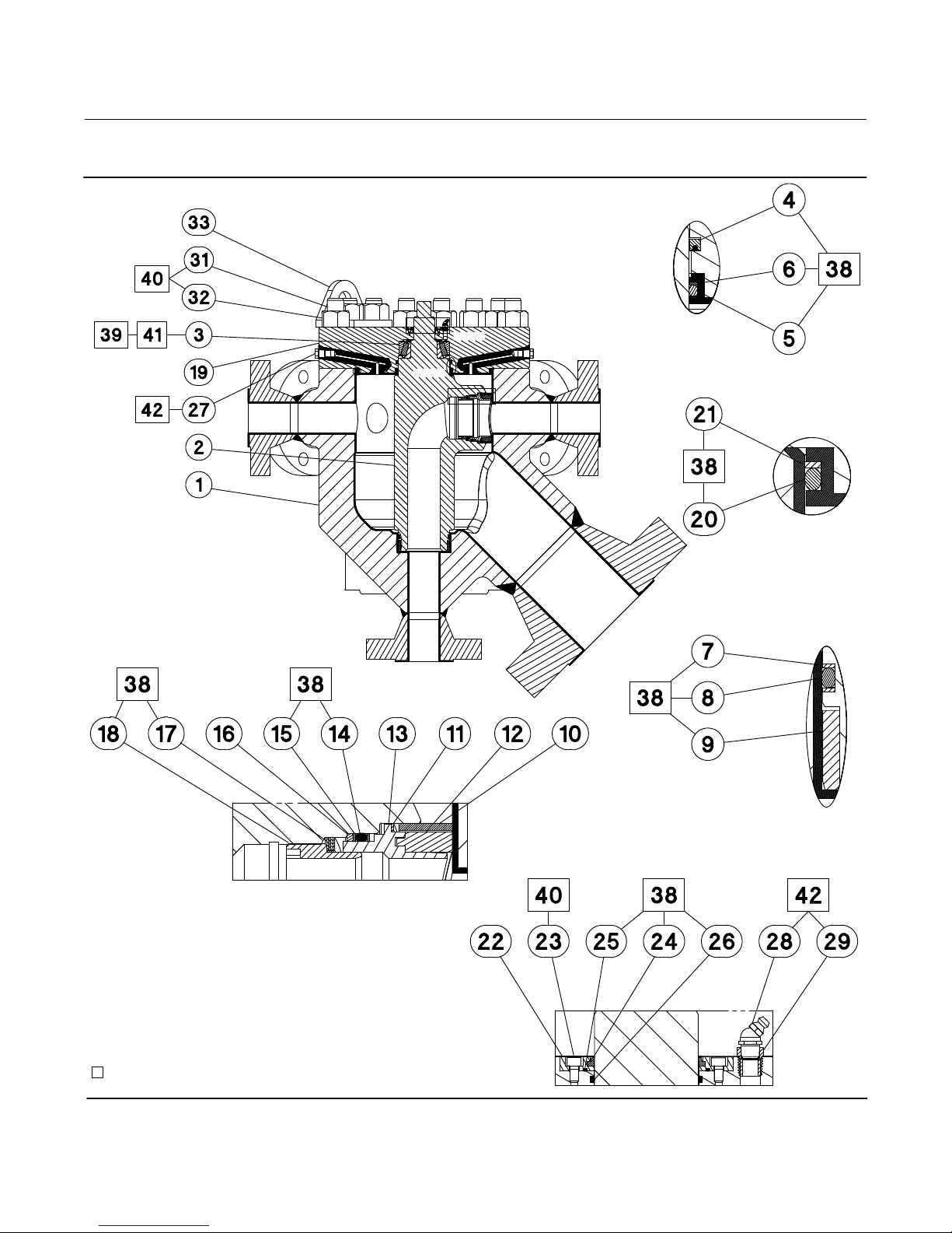
Figure 2. Multiport Drawing Assembly
Instruction Manual
D104239X012
VIEW C
VIEW D
VIEW B
VIEW E
VIEW B
SCALE 2:1
VIEW A
VIEW D
SCALE 2:1
VIEW E
SCALE 3:1
VIEW A
SCALE 2:1
GE99805
APPLY LUB/SEALANT
PARTS NOT SHOWN: 30, 34, 35, 36, AND 37.
12
VIEW C
SCALE 2:1
Instruction Manual
D104239X012
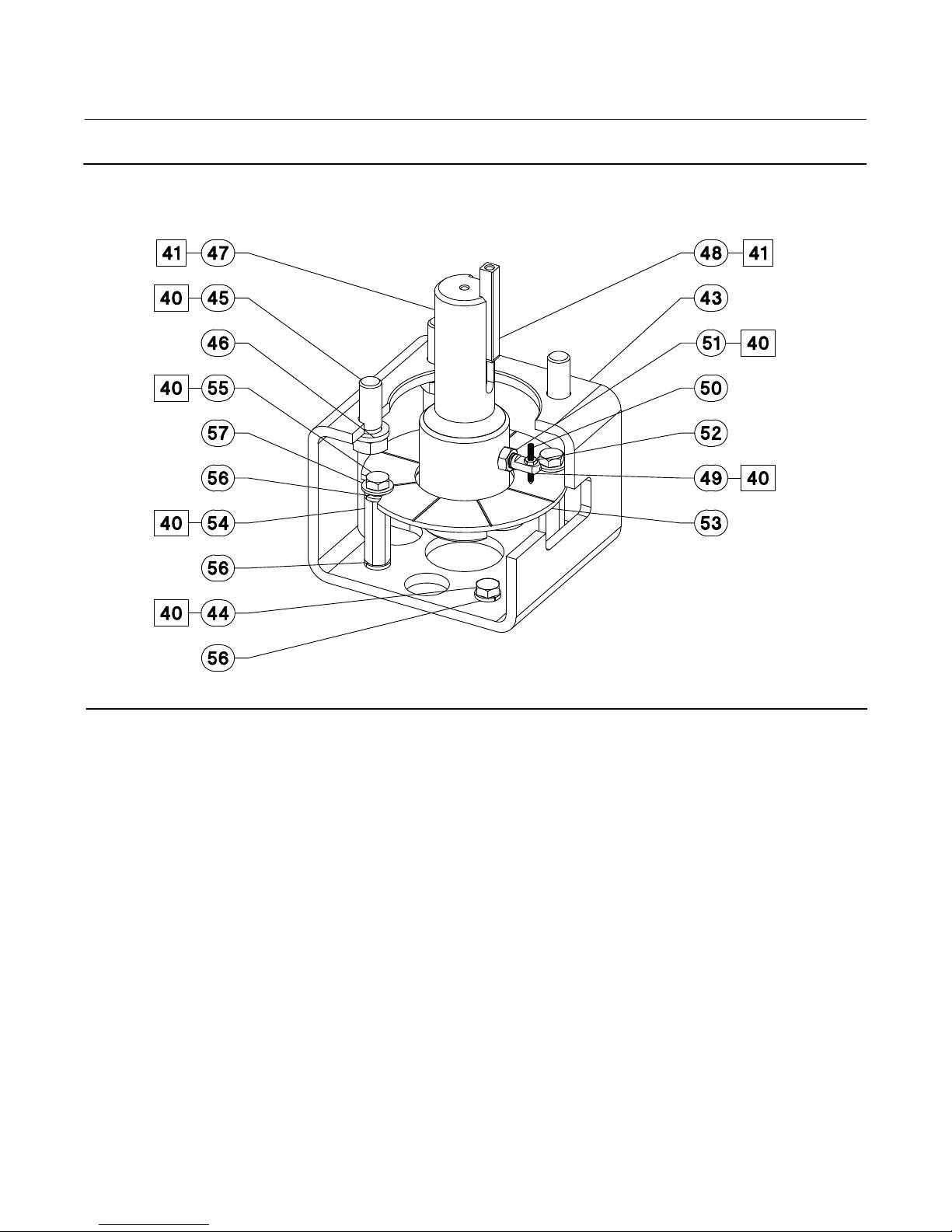
Figure 3. Multiport Mounting Assembly for NPS 3x6, 4x8, and 6x16 Constructions
Multiport Flow Selector
January 2019
GE99891
13

Multiport Flow Selector
January 2019
Parts Kits
Recommend Seal Kits
MAJOR REPAIR KIT, AFLAS FOR 2x4 MPFS RVAE0-960-952
MAJOR REPAIR KIT, AFLAS FOR 3x6 MPFS RVAE0-960-953
MAJOR REPAIR KIT, AFLAS FOR 4x8 MPFS RVAE0-960-954
MAJOR REPAIR KIT, AFLAS/FLEXISEAL FOR 2x4 MPFS RVAE0-960-957
MAJOR REPAIR KIT, AFLAS/KALREZ FOR 3x6 MPFS RVAE0-960-959
HIGH DIFFERENTIAL PLUG UPGRADE, AFLAS FOR 2x4 MPFS RVAE0-960-972
HIGH DIFFERENTIAL PLUG UPGRADE, AFLAS FOR 3x6 MPFS RVAE0-960-973
HIGH DIFFERENTIAL PLUG UPGRADE, AFLAS FOR 4x8 MPFS RVAE0-960-974
HIGH DIFFERENTIAL PLUG UPGRADE, AFLAS/FLEXISEAL FOR 2x4 MPFS RVAE0-960-975
HIGH DIFFERENTIAL PLUG UPGRADE, AFLAS/KALREZ FOR 3x6 MPFS RVAE0-960-976
MINOR REPAIR KIT, AFLAS FOR 3x6 MPFS RVAE0-960-987
MINOR REPAIR KIT, AFLAS/VITON FOR 4x8 MPFS RVAE0-960-988
MINOR REPAIR KIT, AFLAS FOR 2x4 MPFS RVAE0-960-992
MINOR REPAIR KIT, AFLAS/FLEXISEAL FOR 2x4 MPFS RVAE0-960-994
MINOR REPAIR KIT, AFLAS/KALREZ FOR 3x6 MPFS RVAE0-960-997
Instruction Manual
D104239X012
PART NUMBER
Adjustment Tool Kits
DESCRIPTION PART NUMBER
ADJUSTMENT TOOL 2x4 CL 300, 600, and 900 RMP20409X012
ADJUSTMENT TOOL 3x6 CL 150, 300, 600, and 900 RMP30609X012
ADJUSTMENT TOOL 3x6 CL 1500 RMP30615X012
ADJUSTMENT TOOL 4x8 CL 300, 600, and 900 RMP41015X012
ADJUSTMENT TOOL 4x10 CL 1500 RMP41015X012
ADJUSTMENT TOOL 6x16 CL 300, 600, and 900 RMP61609X012
ADJUSTMENT TOOL 6x16 CL 1500 and 2500 RMP61625X012
14

Instruction Manual
D104239X012
Multiport Flow Selector
January 2019
Parts List
WARNING
Use only genuine Fisher replacement parts. Components that are not supplied by Emerson Automation Solutions should
not, under any circumstances, be used in any Fisher valve, because they may void your warranty, might adversely affect the
performance of the valve, and could cause personal injury and property damage.
Key Description
Note
Contact your Emerson sales office
for part ordering information.
Multiport Assembly
(see figure 2 and 3)
Key Description
1 Valve Body
2 Plug
3 Bearing
4 Rod Seal
5 O-Ring, upper plug
6 Back up Ring, upper plug
7 O-Ring, lower plug
8 Back up Ring, lower plug
9 Plug Bushing
10 Scraper
11 Wave Spring Scraper
12 Seal Insert
13 Seal Carrier
14 O-Ring
15 Back up Ring
16 Back up Plate
17 Wave Spring
18 Seal Adjuster
19 Bonnet
20 O-Ring
21 Back up Ring
22 Wiper Retainer
23 Cap Screw, Wiper Retainer
24 Wiper Seal
25 O-Ring, Wiper Retainer
26 O-Ring, Shaft
27 Pipe Plug
28 Lube Fitting
29 Pipe Bushing
30 Set Screw
31 Stud
32 Nut
33 Lifting Lug
38 White Petrolatum
39 High temperature silicone grease
40 Anti-seize lubricant
41 Grease
42 Thread sealant paste
43 Mounting Bracket
44 Cap Screw
45 Cap Screw
46 Lock Washer
47 Coupler
48 Key
49 Travel Indicator Holder
50 Travel Indicator Pointer
51 Jam Nut
52 Nut
53 Travel Indicator Plate
54 Travel Indicator Stud
55 Cap Screw
56 Lock Washer
57 Washer
15

Multiport Flow Selector
January 2019
Figure 4. Typical Multiport Seal Components
Instruction Manual
D104239X012
PLUG SEAL
WAVE SPRINGS
SCRAPER
X1581
SEAL
ADJUST
MENT
NUT
X1582
SEAL
ADJUSTMENT NUT
SCRAPER WAVE
SPRING
PLUG SEAL COMPONENTS
ASSEMBLY
SEAL WAVE
SPRINGS
SEAT RING/
PLATE/
O-RING/
SEAL INSERT
HIGH DIFFERENTIAL SEAL
BEARING
DIFFERENTIAL SEAL
SCRAPER
WAVE
SPRINGS
HIGH
SCRAPER
X1584
BACKUP
PLATE
X1583
O-RING
SEAT
RING
HIGH DIFFERENTIAL
SEAL ASSEMBLY
SEAL ADJUSTMENT TOOL
SEAL
INSERT
ASSEMBLY
NOTE:
1
PLUG SEAL ADJUSTMENT TOOL SHOWN WITH BASE PARALLEL TO SHANK FOR INSERTION, BASE PERPENDICULAR TO SHANK, AND ENGAGED IN SEAL ADUSTMENT NUT.
16

Instruction Manual
D104239X012
Figure 5. Typical Multiport Seal Components
Multiport Flow Selector
January 2019
PLUG
E-60681009
NOTE:
1
PLUG (INDEX MARK CAN BE FOUND ON THE STEM FLAT THAT FACES THE SAME WAY AS THE PLUG SEAL OPENING.) PLUG SEAL ADJUSTMENT TOOL IN PLUG.
SEAL ADJUSTMENT TOOL
17
 Loading...