

Emerson Fisher Large ED, Fisher Large EWT, Fisher Large ET, Fisher Large EWD Instruction Manual
Page 1
Instruction Manual
D103553X012
Large ET and ED Valves
Fisher™ Large ET/EWT and ED/EWD Valves
NPS 12 through 30
July 2017
Contents
Introduction 1.................................
Scope of Manual 1.............................
Educational Services 2.........................
Description 2.................................
Specifications 2...............................
Installation 4..................................
Maintenance 5.................................
Packing Lubrication 6..........................
Packing Maintenance 7.........................
Replacing Packing 7........................
Trim Maintenance 9...........................
Disassembly 9.............................
Valve Plug Maintenance 12..................
Seat Ring Maintenance 15...................
Bore Seal Retrofit 18.......................
Assembly 19..............................
Parts Ordering 20...............................
Parts Kits 20...................................
Parts List 22...................................
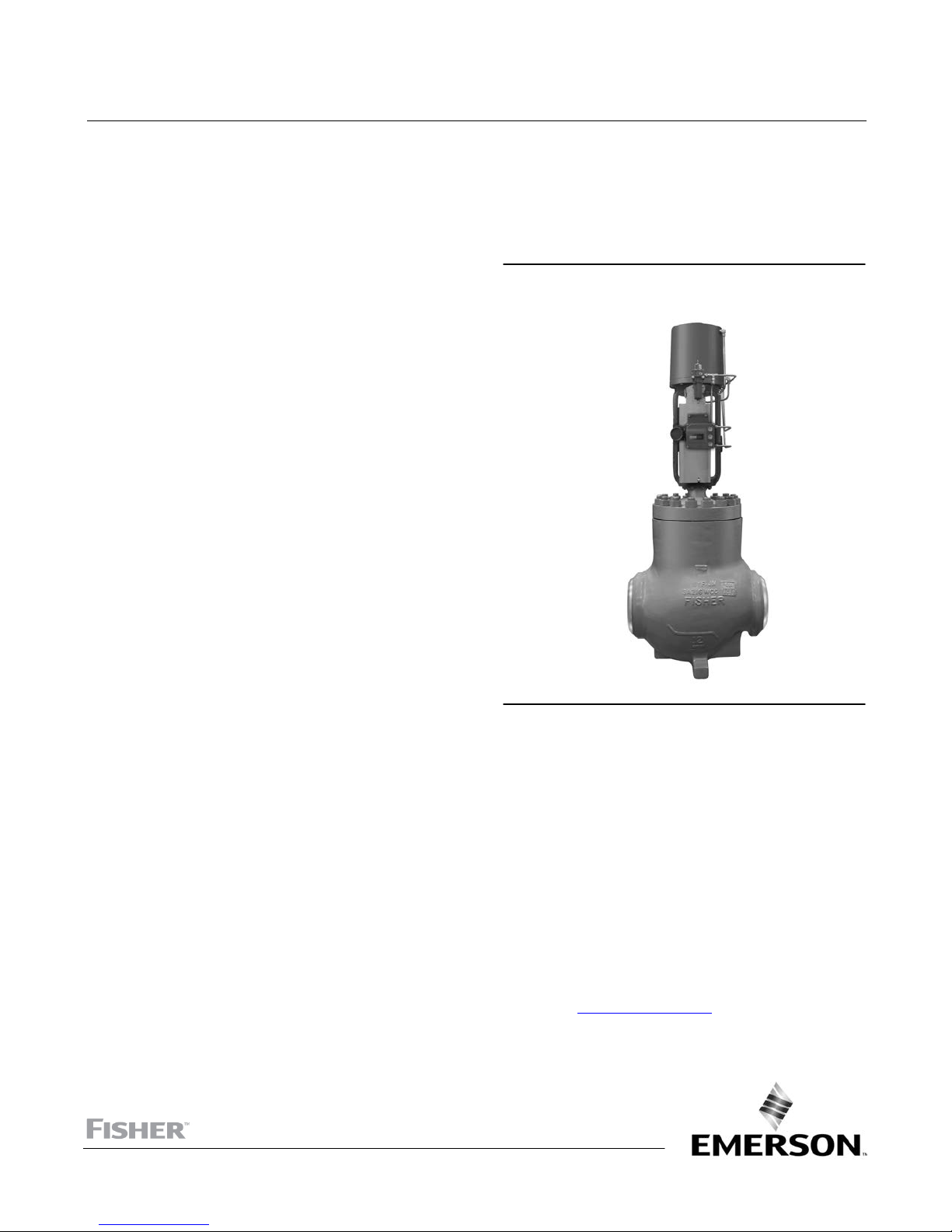
Figure 1. Fisher NPS 12 Valve with Piston Actuator
and FIELDVUE™ DVC6200 Digital Valve Controller
X0237-1
Introduction
Scope of Manual
This instruction manual includes installation, maintenance, and parts information for NPS 12 through 30 Fisher
ET/EWT and ED/EWD valves, through CL600 ratings.
Refer to separate manuals for instructions covering the actuator and accessories.
Do not install, operate, or maintain ET/EWT or ED/EWD valves without being fully trained and qualified in valve,
actuator, and accessory installation, operation, and maintenance. To avoid personal injury or property damage, it is
important to carefully read, understand, and follow all the contents of this manual, including all safety cautions and
warnings. If you have any questions about these instructions, contact your Emerson sales office
Partner before proceeding.
www.Fisher.com
or Local Business
Page 2

Large ET and ED Valves
July 2017
Instruction Manual
D103553X012
Educational Services
For information on available courses for Fisher Large ET/EWT and ED/EWD valves, as well as a variety of other products,
contact:
Emerson Automation Solutions
Educational Services - Registration
Phone: 1-641-754-3771 or 1-800-338-8158
E-mail: education@emerson.com
emerson.com/fishervalvetraining
Description
Fisher NPS 12 through 30 CL150 through CL600 ET/EWT and ED/EWD series control valves are used for either
throttling or on/off control of a wide variety of liquids and gasses.
ET/EWT series valves utilize a hanging cage and a seat ring that is threaded into the cage. These valves have two spring
loaded seal rings, one between the cage and plug and another between the seat ring and valve body, which provide up
to a Class V standard shutoff. They are used for low to medium temperature applications between -46_C (-50_F) and
232_C (450_F). This temperature range can be extended to 316_C (600_F) for nonoxidizing service and to 260_C
(500_F) for oxidizing service by using the High Temperature (HTS1) seal.
The temperature range of the ET/EWT series can be extended to cryogenic temperatures as low as -198_ (-325_F) with
the ET-C and EWT-C specialized versions of these valves. The specialized valves feature unique trim, seals, and a longer
extension bonnet to tolerate the extreme cold.
ED/EWD series valves utilize a hanging cage and a seat ring that is bolted into the body. These valves have two graphite
piston rings between the cage and plug, which provide up to a Class IV standard shutoff. They are used for high
temperature applications between 316_C (600_F) and 593_C (1100_F). Shutoff can be improved to Class V by using
the Bore seal.
A range of severe service trims are available for noise abatement or cavitation control. Noise abatement trims help
with aerodynamic noise attenuation in gas services and feature a Whisper Trim III or WhisperFlo cage. Cavitation
control trims help prevent the damaging effects of liquid cavitation and include either a Cavitrol III cage (for services
without entrained particulate) or Dirty Service Trim (DST) set (for services with entrained particulate).
Specifications
Typical specifications for these valves are shown in table 1.
2
Page 3

Instruction Manual
D103553X012
Table 1. Specifications
Large ET and ED Valves
July 2017
Valve Sizes
ED, ET, and ET-C: J NPS 12, J 14, J 16, J 18, J 20,
and J 30
(2)
EWD, EWT, and EWT-C
: J NPS 16x12, J 20x16,
J 24x16, and J 24x20
End Connection Styles
Flow Characteristics
Standard Cages:J Linear or J Equal percentage
Whisper Trim III and WhisperFlo Cages: Linear
Cavitrol III Cages: Linear
For other characteristics, contact your Emerson sales
office or Local Business Partner for details.
Flanged: CL150, 300, and 600 raised-face or ring-type
joint flanges per ASME B16.5.
NPS 30 valve size has series A or B flanges, per ASME
B16.47
Buttwelding: All ASME B16.25 schedules through
schedule 120 that are compatible with the ASME B16.34
Flow Direction
Standard Cages: Down
Whisper Trim III and WhisperFlo Cages: Up
Cavitrol III Cages: Down
valve body rating
For other end connections, contact your Emerson sales
office or Local Business Partner for details.
Maximum Inlet Pressure
(1)
Flanged: Consistent with CL150, 300, and 600
pressure-temperature ratings per ASME B16.34
Buttwelding: Consistent with CL600
Yoke Boss and Stem Diameters
J 127 mm (5H-inch) diameter yoke boss, with 31.8
mm (1.25 inch) diameter valve stem for all valves except
NPS 30
J 179 mm (7‐inch) diameter yoke boss, with
50.8 mm (2 inch) diameter valve stem for NPS 30 valve
pressure-temperature ratings per ASME B16.34
Shutoff Classifications per ANSI/FCI 70‐2 and IEC
60534‐4
ET, ET-C, EWT, and EWT-C:
Bonnet Style
ED, EWD, ET, and EWT: Style 1 extension
ET-C and EWT-C: Style 3 extension
Standard: Class V
Optional (for all cages except Cavitrol III): Class IV
ED and EWD:
Approximate Weights
Standard: Class IV
Optional: Class V
1. Do not exceed the pressure or temperature limits in this manual, on the equipment nameplate, and any applicable code limitations.
2. Size designations are “end connection size” x “nominal trim size”.
See table 2
3
Page 4
Large ET and ED Valves
July 2017
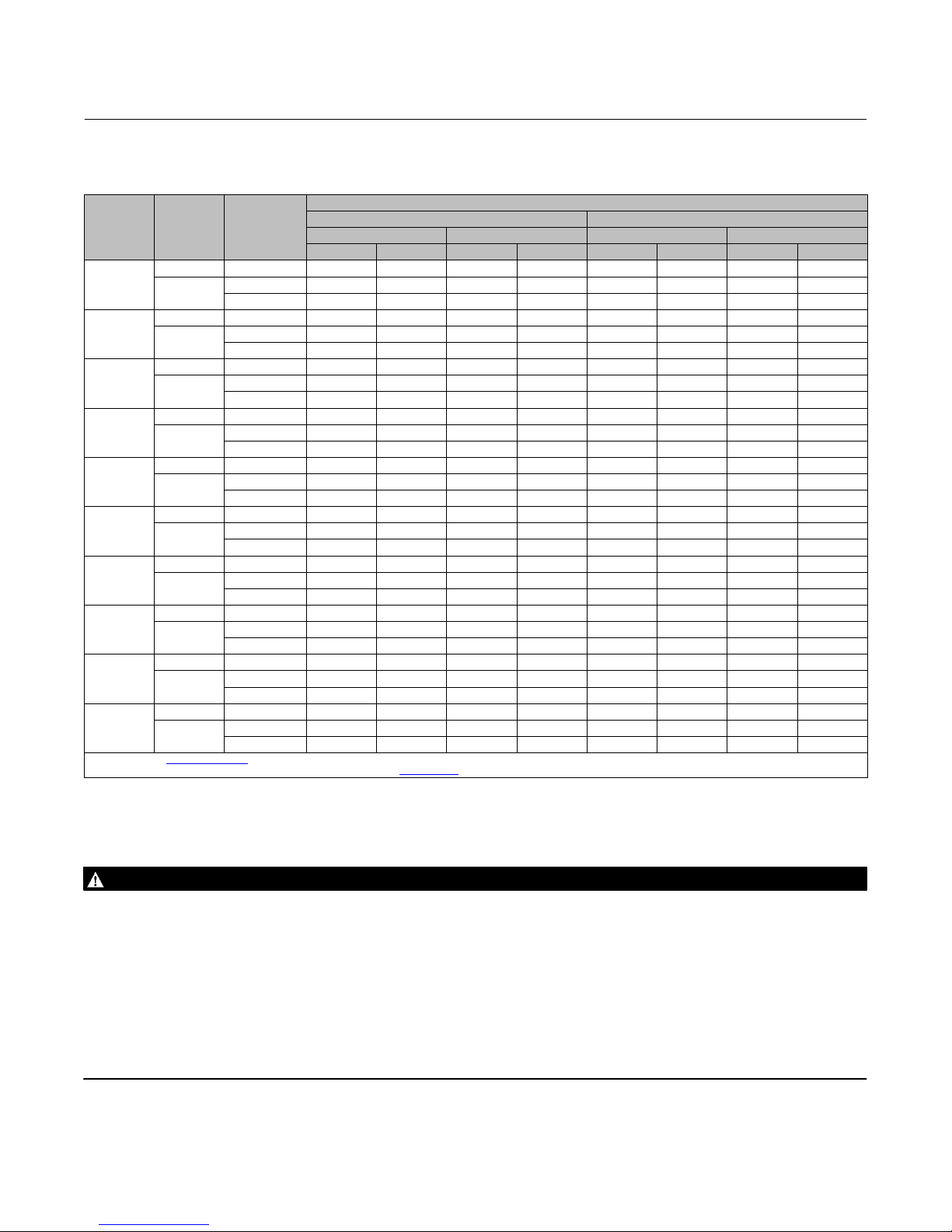
Table 2. Approximate Weights
VALVE
SIZE,
NPS
12
14
16x12
16
18
20x16
24x16
20
24x20
30
1. Contact your Emerson sales office or Local Business Partner for these weights.
2. Dependent on valve travel, refer to product bulletin 51.1:ET/ED (Large) (D103554X012
PRESSURE
CLASS
CL150-300 Flanged 950 2100 1090 2400 982 2170 1122 2470
CL600
CL150-300 Flanged 1130 2500 1230 2700 1162 2570 1262 2770
CL600
CL150-300 Flanged 1320 2900 1450 3200 1352 2970 1482 3270
CL600
CL150-300 Flanged 1720 3800 2040 4500 1752 3870 2072 4570
CL600
CL150-300 Flanged 2310 5100 2500 5500 2342 5170 2532 5570
CL600
CL150-300 Flanged 2500 5500 2680 5900 2532 5570 2712 5970
CL600
CL150-300 Flanged 3360 7400 3810 8400 3392 7470 3842 8470
CL600
CL150-300 Flanged 4122 9088 4526 9978
600
CL150-300 Flanged 5507 12140 5856 12910
600
CL150-300 Flanged 7390 16300 8350 18400 7535 16620 18545 18720
CL600
END
CONNECTION
TYPE
Flanged 1270 2800 1410 3100 1302 2870 1442 3170
Buttwelding 1130 2500 1270 2800 1162 2570 1302 2870
Flanged 1410 3100 1590 3500 1442 3170 1622 3570
Buttwelding 1180 2600 1360 3000 1212 2670 1392 3070
Flanged 1680 3700 1810 4000 1712 3770 1842 4070
Buttwelding 1410 3100 1540 3400 1442 3170 1572 3470
Flanged 2310 5100 2590 5700 2342 5170 2622 5770
Buttwelding 2090 4600 2360 5200 2122 4670 2392 5270
Flanged 2900 6400 3130 6900 2932 6470 3162 6970
Buttwelding 2540 5600 2770 6100 2572 5670 2802 6170
Flanged 3180 7000 3360 7400 3212 7070 3392 7470
Buttwelding 2770 6100 2990 6600 2802 6170 3022 6670
Flanged 4260 9400 4810 10600 4292 9470 4842 10670
Buttwelding 3770 8300 4220 9300 3802 8370 4252 9370
Flanged 4736 10442 5112 11269
Buttwelding 4583 10104 4808 10600
Flanged 6796 14982 7172 15811
Buttwelding 6327 13949 6549 14437
Flanged
Buttwelding
Short Neck
Kg Lb Kg Lb Kg Lb Kg Lb
(1) (1) (1) (1) (1) (1) (1) (1)
(1) (1) (1) (1) (1) (1) (1) (1)
ED/EWD and ET/EWT
(2)
Long Neck
) for addition details.
APPROXIMATE WEIGHT
(2)
Short Neck
(1) (1) (1) (1)
(1) (1) (1) (1)
(1) (1) (1) (1)
(1) (1) (1) (1)
(1) (1) (1) (1)
(1) (1) (1) (1)
Instruction Manual
D103553X012
ET-C/EWT-C
(2)
Long Neck
(2)
Installation
WARNING
Always wear protective gloves, clothing, and eyewear when performing any installation operations to avoid personal
injury.
Personal injury or equipment damage caused by the sudden release of pressure may result if the valve assembly is installed
where service conditions could exceed the limits given in table 1 or on the appropriate nameplates. To avoid such injury or
damage, provide a relief valve for over-pressure protection as required by government or accepted industry codes and
good engineering practices.
Check with your process or safety engineer for any additional measures that must be taken to protect against process
media.
If installing into an existing application, also refer to the WARNING at the beginning of the Maintenance section in this
instruction manual.
4
Page 5

Instruction Manual
D103553X012
Large ET and ED Valves
July 2017
CAUTION
When ordered, the valve configuration and construction materials were selected to meet particular pressure, temperature,
pressure drop, and controlled fluid conditions. Responsibility for the safety of process media and compatibility of valve
materials with process media rests solely with the purchaser and end-user. Since some valve body/trim material
combinations are limited in their pressure drop and temperature ranges, do not apply any other conditions to the valve
without first contacting your Emerson sales office
Before installing the valve, inspect the valve and pipelines for any damage and any foreign material which may cause
product damage.
1. Before installing the valve, inspect the valve and associated equipment for any damage and any foreign material.
2. Make certain that the valve body interior is clean, that pipelines are free of foreign material, and the valve is
oriented so that pipeline flow is in the same direction as the arrow on the side of the valve.
3. The control valve assembly may be installed in any orientation unless limited by seismic criteria. However, the
normal method is with the actuator vertical above the valve. Other positions may result in uneven valve plug and
cage wear and improper operation. Support the actuator if it is not installed in the vertical position. For more
information, consult your Emerson sales office or Local Business Partner.
4. Use accepted piping and welding practices when installing the valve in the line. For flanged valves, use a suitable
gasket between the valve and pipeline flanges.
or Local Business Partner.
CAUTION
Depending on valve body materials used, post weld heat treating may be required. If so, damage to internal elastomeric
and plastic parts, as well as internal metal parts is possible. In general, if post weld heat treating is to be performed, all trim
parts should be removed. Contact your Emerson sales office or Local Business Partner for additional information.
5. With a leak‐off bonnet construction, remove the pipe plugs (key 46) to hook up the leak-off piping. If continuous
operation is required during inspection or maintenance, install a three‐valve bypass around the control valve
assembly.
6. If the actuator and valve are shipped separately, refer to the actuator mounting procedure in the appropriate
actuator instruction manual.
WARNING
Personal injury could result from packing leakage. Valve packing was tightened before shipment; however the packing
might require some readjustment to meet specific service conditions. Check with your process or safety engineer for any
additional measures that must be taken to protect against process media.
Valves with ENVIRO‐SEALt live‐loaded packing or HIGH‐SEAL ULF live‐loaded packing will not require this initial
readjustment. See the Fisher instruction manuals titled ENVIRO‐SEAL Packing System for Sliding‐Stem Valves
(D101642X012
instructions. If you wish to convert your present packing arrangement to ENVIRO-SEAL packing, refer to the retrofit
kits listed in the Parts Kits section.
) or HIGH‐SEAL ULF Live‐Loaded Packing System (D101453X012) (as appropriate) for packing
Maintenance
Unless otherwise noted, refer to the following figures for key numbers: figure 5: ED/EWD Valves, figure 6: ET/EWT
Valves, figure 7: ET/EWT Valves with HTS1 Seals, or figure 8: ET-C/EWT-C Valves.
5
Page 6
Large ET and ED Valves
July 2017
Instruction Manual
D103553X012
Valve parts are subject to normal wear and must be inspected and replaced as necessary. Inspection and maintenance
frequency depends on the severity of service conditions. This section includes instructions for packing lubrication,
packing maintenance, and trim maintenance. All maintenance operations may be performed with the valve in the line.
WARNING
Avoid personal injury or property damage from sudden release of process pressure or bursting of parts. Before performing
any maintenance operations:
D Do not remove the actuator from the valve while the valve is still pressurized.
D Always wear protective gloves, clothing, and eyewear when performing any maintenance operations to avoid personal
injury.
D Disconnect any operating lines providing air pressure, electric power, or a control signal to the actuator. Be sure the
actuator cannot suddenly open or close the valve.
D Use bypass valves or completely shut off the process to isolate the valve from process pressure. Relieve process pressure
on both sides of the valve. Drain the process media from both sides of the valve.
D Vent the pneumatic actuator loading pressure and relieve any actuator spring precompression.
D Use lock‐out procedures to be sure that the above measures stay in effect while you work on the equipment.
D The valve packing box may contain process fluids that are pressurized, even when the valve has been removed from the
pipeline. Process fluids may spray out under pressure when removing the packing hardware or packing rings, or when
loosening the packing box pipe plug.
D Check with your process or safety engineer for any additional measures that must be taken to protect against process
media.
Note
Whenever a gasket seal is disturbed by removing or shifting gasketed parts, a new gasket should be installed upon reassembly.
This is necessary to ensure a good gasket seal because the used gasket might not seal properly.
Packing Lubrication
Note
ENVIRO-SEAL and HIGH-SEAL packing do not require lubrication.
WARNING
To avoid personal injury or property damage resulting from fire or explosion, do not lubricate packing used in oxygen
service or in processes with temperatures over 260_C (500_F).
If a lubricator or lubricator/isolating valve is provided for PTFE/composition or other packings that require lubrication,
it will be installed in place of the pipe plug (key 46). Use a good quality silicon‐base lubricant. To operate the lubricator,
simply turn the cap screw clockwise to force the lubricant into the packing box. The lubricator/isolating valve operates
the same way except open the isolating valve before turning the cap screw and then close the isolating valve after
lubrication is completed.
6
Page 7

Instruction Manual
D103553X012
Large ET and ED Valves
July 2017
Packing Maintenance
Note
For valves with ENVIRO-SEAL packing, see the Fisher instruction manual, ENVIRO-SEAL Packing System for Sliding-Stem Valves,
D101642X012
For valves with HIGH-SEAL packing, see the Fisher instruction manual, HIGH-SEAL ULF Live-Loaded Packing System,
D101453X012
For spring‐loaded single PTFE V‐ring packing, the spring (key 8, figure 2) maintains a sealing force on the packing. If
leakage is noted around the packing follower (key 13, figure 2), check to be sure the shoulder on the packing follower
is touching the bonnet (key 35). If the shoulder is not touching the bonnet, tighten the packing flange nuts (key 5)
until the shoulder is against the bonnet. If leakage cannot be stopped in this manner, proceed to the Replacing
Packing section.
If there is undesirable packing leakage with other than spring‐loaded packing, first try to limit the leakage and
establish a stem seal by tightening the packing flange nuts.
If the packing is relatively new and tight on the valve stem (key 2B) and if tightening the packing flange nuts does not
stop the leakage, it is possible that the valve stem is worn or nicked so that a seal cannot be made. The surface finish of
a new valve stem is critical for making a good packing seal. If the leakage comes from the outside diameter of the
packing, it is possible that the leakage is caused by nicks or scratches around the packing box wall. If performing any of
the following procedures, inspect the valve stem and packing box wall for nicks and scratches.
, for packing instructions.
, for packing instructions.
Replacing Packing
1. Isolate the control valve from the line pressure, release pressure from both sides of the valve, and drain the process
media from both sides of the valve. If using a power actuator, also shut off all pressure lines to the power actuator,
release all pressure from the actuator, and use lock‐out procedures to prevent injury while you work on the
equipment.
2. Remove the actuator from the valve body by following the appropriate Actuator Removal procedure from the
actuator instruction manual.
3. Loosen the packing flange nuts (key 5) so that the packing is not tight on the valve stem (key 2B). Remove any
travel indicator parts and locknuts from the valve stem threads.
WARNING
To avoid personal injury or property damage caused by uncontrolled movement of the bonnet, loosen the bonnet by
following the instructions in the next step. Do not remove a stuck bonnet by pulling on it with equipment that can stretch
or store energy in any other manner. The sudden release of stored energy can cause uncontrolled movement of the bonnet.
CAUTION
Avoid damage to the seating surfaces caused by the valve plug and stem assembly dropping from the bonnet after being
lifted part way out. When lifting the bonnet, temporarily install a locknut on the valve stem. This locknut will prevent the
valve plug and stem assembly (key 2) from dropping out of the bonnet.
If the cage (key 3) starts to lift with the bonnet, tap it with a plastic mallet, or other soft material, to be sure it stays in the
valve body.
Note
The following step also provides additional assurance that the valve body fluid pressure has been relieved.
7
Page 8

Large ET and ED Valves
July 2017
Instruction Manual
D103553X012
4. Hex nuts (key 16) attach the bonnet (key 35) to the valve body. Loosen these nuts or cap screws approximately 3
mm (1/8 inch). Then loosen the body‐to‐bonnet gasketed joint by either rocking the bonnet or prying between the
bonnet and valve body. Work the prying tool around the bonnet until the bonnet loosens. If no fluid leaks from the
joint, remove the nuts completely and carefully lift the bonnet.
5. Remove the locknut from the valve stem and separate the valve plug and stem assembly from the bonnet. Set the
parts on a protective surface to prevent damage to gasket or seating surfaces.
6. Remove the bonnet gasket (key 11) and cover the opening in the valve to protect the gasket surface and prevent
foreign material from getting into the valve body cavity.
CAUTION
To prevent possible product damage, cover the opening in the valve in the following procedure to prevent foreign material
from getting into the valve body cavity.
7. Remove the packing flange nuts (key 5), packing flange (key 37), upper wiper (key 12, figure 2), and packing
follower (key 13, figure 2). Carefully push out all the remaining packing parts from the valve side of the bonnet
using a rounded rod or other tool that will not scratch the packing box wall. Clean the packing box and the metal
packing parts.
8. Inspect the valve stem threads and packing box surfaces for any sharp edges that might cut the packing. Scratches
or burrs could cause packing box leakage or damage to the new packing. If the surface condition cannot be
improved by light sanding, replace the damaged parts by following the appropriate steps in the Trim Maintenance
section.
9. Remove the cover protecting the valve body cavity.
10. Install a new bonnet gasket (key 11), making sure the gasket seating surfaces are clean and smooth. Place the valve
plug and stem assembly into the valve body, making sure it is properly centered on the seat ring (key 9). Also make
sure the valve plug (key 2A) sealing parts are evenly engaged by the chamfer in the top inside diameter of the cage
(key 3) to avoid damaging the parts. Then slide the bonnet over the valve stem (key 2B) and onto the studs (key 15).
Note
Proper performance of the bolting procedures in step 11 compresses the bonnet and cage gaskets (key 11) enough to seal the
body-to-bonnet joint.
The proper bolting procedures in step 11 include--but are not limited to--ensuring that bolting threads are clean and evenly
tightening the hex nuts onto the studs in a crisscross pattern. Tightening one nut may loosen an adjacent nut. Repeat the
crisscross tightening pattern several times until each nut is tight and the body-to-bonnet seal is made.
Studs and hex nuts should be installed such that the manufacturer’s trademark and material grade marking is visible, allowing easy
comparison to the materials selected and documented in the Emerson/Fisher serial card provided with this product.
WARNING
Personal injury or damage to equipment could occur if improper stud and nut materials or parts are used. Do not operate or
assemble this product with stud(s) and nut(s) that are not approved by Emerson/Fisher engineering and/or listed on the
serial card provided with this product. Use of unapproved materials and parts could lead to stresses exceeding the design
or code limits intended for this particular service. Install studs with the material grade and manufacturer's identification
mark visible. Contact your Emerson sales office
approved parts is suspected.
8
or Local Business Partner if a discrepancy between actual parts and
Page 9

Instruction Manual
D103553X012
11. Lubricate the studs (key 15) and install hex nuts (key 16), using accepted bolting procedures during tightening, so
that the body-to-bonnet joint will withstand test pressures and application service conditions. Use the bolt torques
in table 4 as guidelines.
12. Install new packing and the metal packing box parts according to the appropriate arrangement in figure 2. Place a
smooth‐edged pipe over the valve stem, and gently tap each soft packing part into the packing box one piece at a
time, being sure that air is not trapped between adjacent soft parts.
13. Slide the packing follower (key 13, figure 2), upper wiper (key 12, figure 2), and packing flange (key 37) into
position. Lubricate the packing flange studs (key 4) and the faces of the packing flange nuts (key 5). Replace the
packing flange nuts.
14. For spring‐loaded PTFE V‐ring packing, tighten the packing flange nuts until the shoulder on the packing follower
(key 13, figure 2) contacts the bonnet.
For graphite packing, tighten the packing flange nuts to the maximum recommended torque shown in table 3. Then,
loosen the packing flange nuts and retighten them to the recommended minimum torque shown in table 3.
For other packing types, tighten the packing flange nuts alternately in small, equal increments until one of the nuts
reaches the minimum recommended torque shown in table 3. Then, tighten the remaining flange nut until the
packing flange (key 3, figure 2) is at a 90‐degree angle to the valve stem.
15. Mount the actuator on the valve assembly, and reconnect the actuator and valve stem according to the procedure
in the appropriate actuator instruction manual.
Large ET and ED Valves
July 2017
Trim Maintenance
WARNING
Refer to the WARNING at the beginning of the Maintenance section in this instruction manual.
Disassembly
1. Complete steps 1 through 5 of the Replace Packing section to remove the actuator, bonnet, and plug and stem
from the valve body. Remove the bonnet gasket (key 11).
WARNING
To avoid personal injury due to leaking fluid, avoid damaging gasket sealing surfaces. The surface finish of the valve stem
(key 2B) is critical for making a good packing seal. The inside surface of the cage (key 3) is critical for smooth operation of
the valve plug. The seating surfaces of the valve plug (key 2A) and seat ring (key 9) are critical for proper shutoff. Unless
inspection reveals otherwise, assume all these parts are in good condition and protect them accordingly.
2. Packing parts can be removed if desired. Replace these parts as described in the Replace Packing section.
3. Install 3/8”-16 UNC-2A eye bolts with a minimum threaded length of 13 mm (0.5 inches) into the tapped holes in
the top of the cage (key 3) and carefully lift it out of the valve body. For ET/EWT valves, the seat ring (key 9) will be
removed with the cage as an assembly due to the seat ring being screwed into the bottom of the cage and secured
with tack welds. If the cage is stuck in the valve, use a rubber mallet to strike the exposed portion of the cage at
several points around its circumference. Set the part(s) on a protective surface to prevent damage to gasket or
seating surfaces.
4. Remove the cage gasket (key 11).
5. Proceed as appropriate:
9
Page 10

Large ET and ED Valves
July 2017
Figure 2. Typical Packing
UPPER WIPER
(KEY 12)
PACKING
FOLLOWER
(KEY 13)
WASHER
(KEY 10)
SPRING
(KEY 8)
PACKING BOX
RING (KEY 11)
FOR S31600 OR S17400 SST
METAL PACKING BOX PARTS
FEMALE
ADAPTOR
PACKING RING
MALE
ADAPTOR
LOWER WIPER
FEMALE
ADAPTOR
PACKING RING
MALE
ADAPTOR
LOWER
WIPER
FOR ALL OTHER METAL PACKING
PTFE V-RING SINGLE ARRANGEMENTS
BOX PART MATERIALS
Instruction Manual
D103553X012
UPPER WIPER
(KEY 12)
PACKING
FOLLOWER
(KEY 13)
SPACER (KEY 8)
PACKING BOX
RING (KEY 11)
ASSEMBLY 1
(POSITIVE
PRESSURES)
ASSEMBLY 2
(VACUUM)
ASSEMBLY 3
(POSITIVE
PRESSURES &
VACUUM)
31.8 and 50.8 mm
(1-1/4 and 2 INCH) STEM
PTFE V-RING
DOUBLE ARRANGEMENTS
NOTE:
PACKING SET (KEY 6) (2 REQUIRED FOR DOUBLE ARRANGEMENTS)
B2398
UPPER WIPER
(KEY 12)
PACKING
FOLLOWER
(KEY 13)
MALE
ADAPTOR
PACKING
RING
FEMALE
ADAPTOR
LANTERN RING
(KEY 8)
PACKING BOX
RING (KEY 11)
LOWER
WIPER
1
1
1
UPPER WIPER
(KEY 12)
PACKING
FOLLOWER
(KEY 13)
PACKING RING (KEY 7)
LANTERN RING
(KEY 8)
PACKING BOX
RING (KEY 11)
31.8 and 50.8 mm
(1-1/4 and 2 INCH) STEM
PTFE/COMPOSITION
ARRANGEMENT
10
Page 11

Instruction Manual
D103553X012
Figure 2. Typical Packing (Continued)
PACKING
FOLLOWER
(KEY 13)
GRAPHITE RIBBON
PACKING RING (KEY 7)
PACKING
FOLLOWER
(KEY 13)
GRAPHITE RIBBON
PACKING RING (KEY 7)
Large ET and ED Valves
July 2017
GRAPHITE FILAMENT
PACKING RING (KEY 7)
LANTERN RING
(KEY 8)
PACKING BOX
RING (KEY 11)
31.8 and 50.8 mm
(1-1/4 and 2 INCH) STEM
SINGLE ARRANGEMENT
31.8 and 50.8 mm
(1-1/4 and 2 INCH) STEM
DOUBLE ARRANGEMENT
GRAPHITE FILAMENT
PACKING RING (KEY 7)
LANTERN RING
(KEY 8)
PACKING BOX
RING (KEY 11)
GRAPHITE RIBBON/FILAMENT PACKING
NOTE:
0.102 mm (0.004 INCH) THICK SACRIFICIAL ZINC WASHERS:
USE ONLY ONE BELOW EACH GRAPHITE RIBBON RING.
A6060
Table 3. Packing Flange Nut Torque for Packing Without a Spring
VALVE STEM
DIAMETER
mm Inch NSm LbfSft NSm LbfSft NSm LbfSft NSm LbfSft
31.8 1‐1/4
50.8 2
PRESSURE
RATING
Minimum Torque Maximum Torque Minimum Torque Maximum Torque
CL150 & 300
CL600
CL300 43 32 65 48 20 15 31 23
CL600 61 45 91 67 27 20 41 30
GRAPHITE‐TYPE PACKING PTFE‐TYPE PACKING
33
45
24.3
33.2
49
67
36.1
49.4
16
21
11.8
15.5
25
33
Table 4. Body‐to‐Bonnet Bolt Torque
BOLT SIZE, INCH THREADS PER INCH
1-1/4 8 990 730
1-1/2 8 1750 1290
1-3/4 8 2806 2070
2 8 4244 3130
1. Torque values listed apply to the following stud and nut materials lubricated with Lubriplate MAG-1.
• SA-193-B7 studs with SA-194-2H nuts
• SA-193-B7M studs with SA-194-2HM nuts
• SA-193-B16 studs with SA-194-7 nuts
• SA-193-B8M Class 2 studs with SA-194-8M nuts
• N07718 HT studs with N07718 HT chrome coat nuts
• SA479 S20910 chrome coat studs with SA479 S20910 nuts
BOLTING TORQUE
NSm LbfSft
(1)
18.4
24.3
For ET/EWT Valves, using the below procedure, disassemble the seat ring from the cage:
a. Grind or file off the two tack welds that prevent the seat ring from unscrewing from the cage.
b. Install 3/8'-16 UNC-2A bolts or cap screws into the two equally spaced tapped holes in the bottom of the seat
ring. These bolts or cap screws will need to have a minimum of 0.5 inches of thread engagement and the length
will be determined by the pry bar diameter used in this step.
c. Using a pry bar to pry against the cap screws, turn the seat ring counter-clockwise to unscrew it from the cage.
d. Set the seat ring on a protective surface taking care not to damage the seat ring seal ring (key 223).
11
Page 12

Large ET and ED Valves
July 2017
Instruction Manual
D103553X012
For ED/EWD and ET-C/EWT-C Valves, using the below procedure, disassemble the seat ring from the valve body:
a. Unscrew the seat ring cap screws (key 49).
b. Install 3/8”-16 eye bolts with a minimum threaded length of 0.5 inches into the two equally spaced tapped holes
in the top of the seat ring (key 9).
c. Carefully lift the seat ring out of the valve body using the eye bolts as lifting points.
d. Set the seat ring on a protective surface.
e. Remove the seat ring gasket (key 13) from the valve body.
6. Cover the opening in the valve to protect the gasket surface and prevent foreign material from getting into the
valve body cavity. Inspect parts for wear and damage which would prevent proper operation of the valve. If the cage
requires replacement take note that for ET/EWT valves a replacement is available individually (key 3 only) or as a
cage and seat ring assembly (key 3 and 9). The valve plug and seat ring, along with their respective sealing parts, will
be inspected in the Valve Plug and Seat Ring maintenance procedures.
Valve Plug Maintenance
With the valve plug and stem assembly (key 2) removed according to the Disassembly procedure, proceed as
appropriate:
CAUTION
Be careful not to scratch the surfaces of the seal ring grooves in the valve plug (key 2A) or any surfaces of the replacement
parts.
For ET/EWT Valves
1. Carefully pry or cut out the plug seal ring (key 28) from its groove in the valve plug (key 2A). Discard the old plug
seal ring.
2. Inspect the valve plug (key 2A) and stem (key 2B) for nicks, scratches, or other damage that would prevent proper
operation of the valve. If replacement of either is necessary, replace as a complete valve plug and stem assembly
(key 2).
CAUTION
To avoid damaging the seal ring, slowly and gently stretch it for the following procedure. Avoid jerking sharply on the ring.
3. Install the replacement plug seal ring (key 28) with the open side facing the top or bottom of the valve plug,
depending on flow direction. The open side of the seal ring should face up (toward the actuator) in flow-up
installations and down in flow-down installations.
To install the seal ring on the valve plug, first lubricate it with a general purpose silicone-base lubricant. Then gently
stretch the seal ring and work it over the top edge of the valve plug. The PTFE material in the seal ring must be
permitted time to cold-flow during the stretching procedure, so avoid jerking sharply on the ring. Stretching the seal
ring over the valve plug may make it seem unduly loose when in the groove, but it will contract to its original size after
insertion into the cage.
12
Page 13

Instruction Manual
D103553X012
Large ET and ED Valves
July 2017
For ET/EWT Valves Equipped with HTS1 Seals
1. Carefully pry the plug retaining ring (key 27) from its groove in the valve plug (key 2A). Then remove the plug seal
ring (key 28), backup ring (key 29), and anti-extrusion ring (key 63). Inspect the retaining ring and backup ring for
damage and replace as needed. Discard the old plug seal ring and anti-extrusion ring.
2. Inspect the valve plug (key 2A) and stem (key 2B) for nicks, scratches, or other damage that would prevent proper
operation of the valve. If replacement of either is necessary, replace as a complete valve plug and stem assembly
(key 2).
3. Install the replacement plug seal ring (key 28) and anti-extrusion ring (key 63) with the open side of the seal ring
facing the top or bottom of the valve plug, depending on flow direction. The open side of the seal ring should face
up (toward the actuator) in flow-up installations and down in flow-down installations. Make sure the anti-extrusion
ring is adjacent to the closed side of the seal ring. Then install the plug backup ring (key 29) and retaining ring
(key 27).
To install the parts on the valve plug, first lubricate each with a general purpose silicone-base lubricant. Then gently
slide each over the top edge of the valve plug.
For ET-C/EWT-C Valves
1. Carefully pry the plug retaining ring (key 27) from its groove in the valve plug (key 2A). Then remove the plug seal
ring (key 28) and backup ring (key 29). Inspect the retaining ring and backup ring for damage and replace as
needed. Discard the old plug seal ring.
2. Inspect the valve plug (key 2A) and stem (key 2B) for nicks, scratches, or other damage that would prevent proper
operation of the valve. If replacement of either is necessary, replace as a complete valve plug and stem assembly
(key 2).
3. Install the replacement plug seal ring (key 28) with the open side of the seal ring facing the top or bottom of the
valve plug, depending on flow direction. The open side of the seal ring should face up (toward the actuator) in
flow-up installations and down in flow-down installations. Then install the plug backup ring (key 29) and retaining
ring (key 27).
To install the parts on the valve plug, first lubricate each with a general purpose silicone-base lubricant. Then gently
slide each over the top edge of the valve plug.
For ED/EWD Valves
1. Remove and discard the piston rings (key 6). The rings can be easily removed since each is in two pieces.
2. Inspect the valve plug (key 2A) and stem (key 2B) for nicks, scratches, or other damage that would prevent proper
operation of the valve. If replacement of either is necessary replace as a complete valve plug and stem assembly
(key 2).
3. Each new piston ring (key 6) is furnished as a complete ring, and each must be broken into two approximately equal
portions. Do this by placing the ring on edge on a smooth, hard surface and striking the ring squarely with a
hammer.
4. Install the replacement piston ring(s) into the groove(s) in the valve plug (key 2A). Be sure to match the broken
ends when installing the ring sections in the groove(s).
For ED/EWD Valves Equipped with the Bore Seal
1. Remove and discard the piston ring (key 6). The ring can be easily removed since it is in two pieces. Also inspect the
bore seal (key 64) and retainer (key 2C) for nicks, scratches, or other damage that would prevent proper operation
of the valve. If replacement of the bore seal is necessary complete steps 2 – 12, otherwise proceed directly to
step 13.
2. Referring to figure 3, locate the staked thread on top of the valve plug (key 2A). The staked thread secures the
retainer (key 2C). Use a drill with a 1/8 inch bit to drill out the staked area of the thread. Drill approximately 1/8 inch
into the metal to remove the staking.
13
Page 14

Large ET and ED Valves
July 2017
Instruction Manual
D103553X012
3. Referring to figure 3, locate the 1/4-inch diameter hole in the groove where the piston ring was installed.
4. Select an appropriate tool such as a punch and place the tip of the tool into the hole with the body of the tool held
tangent to the outside diameter of the retainer. Strike the tool with a hammer to rotate the retainer and free it from
the valve plug. Remove the retainer from the valve plug.
5. Use an appropriate tool such as a flat-blade screwdriver to pry the bore seal (key 64) off the valve plug. Use caution
to avoid scratches or other damage to the seating surfaces where the bore seal makes contact with the valve plug
(see figure 3).
Figure 3. Fisher ED/EWD Valve Equipped with the Bore Seal
1/4” DIA HOLE
(BEHIND THE PISTON RING)
PISTON RING
CAGE
SEATING AREA
BORE SEAL
STAKE
THREADS
HERE
PLUG
RETAINER
FLOW DOWN
1/4” DIA HOLE
(BEHIND THE PISTON RING)
PISTON RING
CAGE
SEATING AREA
BORE SEAL
STAKE
THREADS
HERE
PLUG
RETAINER
FLOW UP
6. Apply a suitable high-temperature lubricant to the inside diameter of the bore seal. Also, lubricate the outside
diameter of the valve plug where the bore seal must be pressed into the proper seating position (see figure 3).
7. Referring to figure 3, orient the bore seal for correct sealing action based on the process fluid flow direction through
the valve.
D The open interior of the bore seal must face up in a valve with flow-up construction.
D The open interior of the bore seal must face down in a valve with flow-down construction.
8. Place the bore seal over the top of the valve plug. The retainer will help guide the bore seal down onto the valve
plug. Do not force the bore seal over the valve plug. For flow down constructions, skip to step 10.
9. An installation tool (see figure 4 and table 5) must be inserted into the bore seal prior to using the retainer to guide
it down the valve plug.
10. Apply a suitable high-temperature lubricant to the threads on the valve plug. Then, place the retainer onto the
valve plug and tighten the retainer using an appropriate tool such as a strap wrench. For flow-down constructions,
skip to step 12.
11. Remove the retainer and then the installation tool. Place the retainer back onto the valve plug and tighten the
retainer using an appropriate tool such as a strap wrench.
12. Using an appropriate tool such as a center punch, stake the threads on top of the valve plug in one place to secure
the retainer (see figure 3).
13. Inspect the valve plug (key 2A) and stem (key 2B) for nicks, scratches, or other damage that would prevent proper
operation of the valve. If replacement of either is necessary replace as a complete valve plug and stem assembly
(key 2).
14
Page 15

Instruction Manual
D103553X012
Large ET and ED Valves
July 2017
14. Each new piston ring (key 6) is furnished as a complete ring, and each must be broken into two approximately equal
portions. Do this by placing the ring on edge on a smooth, hard surface and striking the ring squarely with a
hammer.
15. Install the piston ring into the groove in the retainer (key 2C). Be sure to match the broken ends when installing the
ring sections in the groove.
CAUTION
To avoid excessive leakage and seat erosion, the valve plug must be initially seated with sufficient force to overcome the
resistance of the Bore Seal and contact the seat ring. You can correctly seat the valve plug by using the same force
calculated for full load when sizing your actuator. With no pressure drop across the valve, this force will adequately drive
the valve plug to the seat ring, thus giving the Bore Seal a predetermined permanent set.
With full actuator force applied and the valve plug fully seated, align the actuator travel indicator scale with the lower end
of valve travel. Refer to the appropriate actuator instruction manual for information on this procedure.
Seat Ring Maintenance
With the seat ring (key 9) removed, according to the Disassembly procedure, proceed as appropriate:
CAUTION
Be careful not to scratch the surfaces of the seating surface or groove in the seat ring or the surfaces of the replacement
parts.
15
Page 16

Large ET and ED Valves
July 2017
Figure 4. Bore Seal Installation Tool
Instruction Manual
D103553X012
GE22109-A
F
G
H
E
A
B
C
D
Table 5. Bore Seal Installation Tool Dimensions
VALVE
PORT SIZE,
INCH
10.00 10.12 9.7 9.80-9.82 10.00-10.02 0.10 0.10 0.32 R.06 GE17914X012
11.00 12.59 12.17 12.27-12.29 12.49-12.47 0.10 0.10 0.32 R.07 GE18183X012
14.75 14.84 14.424-14.416 14.516-14.536 14.736-14.716 0.10 0.10 0.32 R.05 GE34073X012
18.25 18.35 17.925-17.935 18.030-18.050 18.230-18.250 0.10 0.10 0.32 R.06 GG43649X012
24.00
1. Contact your Emerson sales office or Local Business Partner for this tool and dimensions.
A B C D E F G H
Dimensions, Inches (See Figure 4)
(1) (1)
Tool Part
Number
For ET/EWT Valves
1. Carefully pry or cut out the seat ring seal ring (key 223) from its groove in the seat ring (key 9). Discard the old seat
ring seal ring.
2. Then inspect the seat ring (key 9) for nicks, scratches, or other damage that would prevent proper operation of the
valve. Replace the seat ring if necessary. A replacement seat ring is available individually (key 9 only) or as a seat ring
and cage assembly (key 9 and 3). If replacing individually proceed to step 3, otherwise proceed directly to step 7.
3. Make sure the bolts or cap screws that were installed in the seat ring during the Disassembly procedure are still
installed.
4. Orient the cage (key 3) and seat ring so that the threads on each are facing one another for assembly. The bottom
of the cage should be facing the top of the seat ring.
5. Using a pry bar to pry against the bolts or cap screws, turn the seat ring clockwise into the cage until tight.
Afterwords remove the two bolts or cap screws.
16
Page 17

Instruction Manual
D103553X012
Large ET and ED Valves
July 2017
6. Tack weld the seat ring to the cage using minimal heat. Two welds, 6 mm (1/4-inch) long and 180 degrees apart,
are required.
CAUTION
To avoid damaging the seal ring, slowly and gently stretch it for the following procedure. Avoid jerking sharply on the ring.
7. Install the replacement seat ring seal ring (key 223) with the open side facing the top or bottom of the seat ring,
depending on flow direction. The open side of the seal ring should face down (toward the bottom of the valve body)
in flow-up installations and up in flow-down installations.
To install the seal ring on the seat ring, first lubricate it with a general purpose silicone-base lubricant. Then gently
stretch the seal ring and work it over the bottom edge of the seat ring. The PTFE material in the seal ring must be
permitted time to cold-flow during the stretching procedure, so avoid jerking sharply on the ring. Stretching the
seal ring over the seat ring may make it seem unduly loose when in the groove, but it will contract to its original size
after insertion into the valve body.
For ET/EWT Valves Equipped with HTS1 Seals
1. Carefully pry the seat ring retaining ring (key 221) from its groove in the seat ring (key 9). Then remove the seat ring
seal ring (key 223), backup ring (key 220), and anti-extrusion ring (key 219). Inspect the retaining ring and backup
ring for damage and replace as needed. Discard the old seat ring seal ring and anti-extrusion ring.
2. Then inspect the seat ring (key 9) for nicks, scratches, or other damage that would prevent proper operation of the
valve. Replace the seat ring if necessary. A replacement seat ring is available individually (key 9 only) or as a seat ring
and cage assembly (key 9 and 3). If replacing individually proceed to step 3, otherwise proceed directly to step 7.
3. Make sure the bolts or cap screws that were installed in the seat ring during the Disassembly procedure are still
installed.
4. Orient the cage and seat ring so that the threads on each are facing one another for assembly. The bottom of the
cage should be facing the top of the seat ring.
5. Using a pry bar to pry against the bolts or cap screws, turn the seat ring clockwise into the cage until tight.
Afterwords remove the two bolts or cap screws.
6. Tack weld the seat ring to the cage using minimal heat. Two welds, 6 mm (1/4-inch) long and 180 degrees apart,
are required.
7. Install the replacement seat ring seal ring (key 223) and anti-extrusion ring (key 219) with the open side of the seal
ring facing the top or bottom of the seat ring, depending on flow direction. The open side of the seal ring should
face down (toward the bottom of the valve body) in flow-up installations and up in flow-down installations. Make
sure the anti-extrusion ring is adjacent to closed side of the seal ring. Then install the seat ring backup ring (key 220)
and retaining ring (key 221).
To install the parts on the seat ring, first lubricate each with a general purpose silicone-base lubricant. Then gently
slide each over the bottom edge of the seat ring.
For ED/EWD and ET-C/EWT-C Valves
1. Inspect the seat ring (key 9) for nicks, scratches, or other damage that would prevent proper operation of the valve.
Replace if necessary.
17
Page 18

Large ET and ED Valves
July 2017
Instruction Manual
D103553X012
Bore Seal Retrofit
Note
Additional actuator thrust is required for a valve equipped with the bore seal. When installing the bore seal in an existing valve,
contact your Emerson sales office
or Local Business Partner for assistance in determining new actuator thrust requirements.
The bore seal retrofit will require a new valve plug and stem assembly (key 2), bore seal (key 64), and piston ring
(key 6). The following steps will guide you in the assembly of these parts. Final installation into the valve body will be
per the Assembly procedure.
CAUTION
To avoid leakage when the valve is returned to service, use appropriate methods and materials to protect all sealing
surfaces of the new trim parts while assembling the individual parts and during installation in the valve body.
1. Apply a suitable high-temperature lubricant to the inside diameter of the bore seal. Also, lubricate the outside
diameter of the valve plug where the bore seal must be pressed into the proper seating position (see figure 3).
2. Referring to figure 3, orient the bore seal for correct sealing action based on the process fluid flow direction through
the valve.
D The open interior of the bore seal must face up in a valve with flow-up construction.
D The open interior of the bore seal must face down in a valve with flow-down construction.
3. Place the bore seal over the top of the valve plug. The retainer will help guide the bore seal down onto the valve
plug. Do not force the bore seal over the plug. For flow-down constructions, skip to step 5.
4. An installation tool (see figure 4 and table 5) must be inserted into the bore seal prior to using the retainer to guide
it down the valve plug.
5. Apply a suitable high-temperature lubricant to the threads on the valve plug. Then, place the retainer onto the valve
plug and tighten the retainer using an appropriate tool such as a strap wrench. For flow-down constructions, skip to
step 7.
6. Remove the retainer and then the installation tool. Place the retainer back onto the valve plug and tighten the
retainer using an appropriate tool such as a strap wrench.
7. Using an appropriate tool such as a center punch, stake the threads on top of the valve plug in one place to secure
the retainer (see figure 3).
8. Each new piston ring (key 6) is furnished as a complete ring, and each must be broken into two approximately equal
portions. Do this by placing the ring on edge on a smooth, hard surface and striking the ring squarely with a
hammer.
9. Install the piston ring into the groove in the retainer (key 2C). Be sure to match the broken ends when installing the
ring sections in the groove.
CAUTION
To avoid excessive leakage and seat erosion, the valve plug must be initially seated with sufficient force to overcome the
resistance of the Bore Seal and contact the seat ring. You can correctly seat the valve plug by using the same force
calculated for full load when sizing your actuator. With no pressure drop across the valve, this force will adequately drive
the valve plug to the seat ring, giving the Bore Seal a predetermined permanent set.
With full actuator force applied and the valve plug fully seated, align the actuator travel indicator scale with the lower end
of valve travel. Refer to the appropriate actuator instruction manual for information on this procedure.
18
Page 19

Instruction Manual
D103553X012
Large ET and ED Valves
July 2017
Assembly
After completing Packing Maintenance and/or Trim Maintenance procedures, the following steps will guide you
through reassembly of the valve.
For ED/EWD and ET-C/EWT-C Valves only
1. Remove the cover protecting the valve body cavity.
2. Install a new seat ring gasket (key 13) into the valve body. Make sure the eye bolts that were installed in the seat
ring (key 9) during the Disassembly procedure are still installed. Then using the eye bolts as lifting points, carefully
lower the seat ring into the valve body. Make sure that the cap screw holes in the seat ring are lined up with their
mating holes in the valve body. Remove the two eye bolts from the seat ring.
CAUTION
Uneven tightening of the cap screws (key 49) will result in the seat ring seating surface being askew from the valve plug
seating surface, thereby preventing the valve from attaining its rated shutoff class. This is especially critical in ED/EWD
valves equipped with the bore seal. If after assembly the rated shutoff class is not attained your Emerson sales office
Local Business Partner can provide further assistance.
or
3. Secure the seat ring to the valve body using the cap screws (key 49). Tighten the cap screws in a criss-cross pattern
working up to the final torque in four equal increments as specified in table 6.
4. Install a new cage gasket (key 11) into the valve body.
5. Make sure the eye bolts that were installed in the cage (key 3) or cage assembly during the Disassembly procedure
are still installed. Then using the eye bolts as lifting points, carefully lower the cage into the valve body. Any
rotational orientation of the cage with respect to the valve is acceptable.
6. Complete reassembly according to steps 10 through 15 of the Replace Packing section.
Table 6. Seat Ring Cap Screw Torque
VALVE SIZE, NPS
12, 14, and 16x12 9.75 7 19.5 14 29.25 21 39 28
16, 18, 20x16, 24x16, 20, 24x20, and 30 23 17 46 34 69 51 92 68
FIRST INCREMENT SECOND INCREMENT THIRD INCREMENT
N•m Lbf•ft N•m Lbf•ft N•m Lbf•ft N•m Lbf•ft
FOURTH INCREMENT
FINAL TORQUE
For ET/EWT Valves only
1. Remove the cover protecting the valve body cavity.
2. Install a new cage gasket (key 11) into the valve body.
3. Make sure the eye bolts that were installed in the cage (key 3) or cage assembly during the Disassembly procedure
are still installed. Then using the eye bolts as lifting points, carefully lower the cage into the valve body. Any
rotational orientation of the cage with respect to the valve is acceptable. Use care to avoid damaging the seat ring
seal ring (key 223) while handling the heavy parts. To help insert the cage assembly into the valve, lubricate the
outside diameter of the seat ring seal ring with general purpose silicone-base lubricant.
4. Complete reassembly according to steps 10 through 15 of the Replace Packing section.
19
Page 20

Large ET and ED Valves
July 2017
Instruction Manual
D103553X012
Parts Ordering
Each body‐bonnet assembly is assigned a serial number, which can be found on the valve. This same number also
appears on the actuator nameplate when the valve is shipped from the factory as part of a control valve assembly.
Refer to the serial number when contacting your Emerson sales office
or Local Business Partner for technical
assistance.
WARNING
Use only genuine Fisher replacement parts. Components that are not supplied by Emerson Automation Solutions should
not, under any circumstances, be used in any Fisher valve, because they may void your warranty, might adversely affect the
performance of the valve, and could cause personal injury and property damage.
Parts Kits
Seal Ring and Piston Ring Kits
Repair kits include parts to replace the seal rings and piston rings for the valve plug and seat ring.
ED/EWD Valves ET/EWT Valves
Valve Size, NPS
12, 14, 16x12
16, 18, 20x16, 24x16
20, 24x20
30
Port Diameter,
mm (Inch)
254 (10) RSEALX00012 Consult factory RSEALX00042 RSEALX00062 RSEALX00082
279 (11) RSEALX00022 RSEALX00032 RSEALX00052 RSEALX00072 RSEALX00092
375 (14.75) RSEALX00102 RSEALX00112 RSEALX00122 RSEALX00142 RSEALX00162
413 (16.25) - - - - - - RSEALX00132 RSEALX00152 - - -
18.25 RSEALX00192 RSEALX00202 RSEALX00212 RSEALX00232 RSEALX00252
19.75 - - - - - - RSEALX00222 RSEALX00242 - - 610 (24) Consult factory Consult factory RSEALX00172 Consult factory Consult factory
660 (26) - - - - - - RSEALX00182 Consult factory - - -
Standard
(includes key 6)
With Bore Seal
(includes key 6)
Standard
(includes keys
28 and 223)
With HTS1 Seals
(includes keys
28, 63, 223, and
219)
ET-C/EWT-C
(includes key 28)
Gasket Kits
Valve Size, NPS
12, 14, 16x12 All RGASKETXE62 RGASKETXE92
16, 18, 20x16, 24x16 less than 378 (14.88) RGASKETXE72 RGASKETXF12
20x16 378 (14.88) RGASKETXE82 RGASKETXF22
20, 24x20 203 (8.00), 276 (10.88), 378 (14.88) RGASKETXF42 RGASKETXF62
24x20 429 (16.88) RGASKETXF52 RGASKETXF72
30 All Consult factory RGASKETXF32
Standard Packing Kits (Non Live-Loaded)
Stem Diameter, mm (Inches)
Yoke Boss Diameter, mm (Inches)
Single PTFE (Contains keys 6, 8, 10, 11, and 12) RPACKX00352 Consult factory
Double PTFE (Contains keys 6, 8, 11, and 12) RPACKX00372 Consult factory
Single Graphite Ribbon/Filament (Contains keys
7 [ribbon ring], 7 [filament ring], and 11)
20
Valve Travel,
mm (Inch)
ED/EWD and ET-C/EWT-C Valves
(includes keys 11 and 13)
31.8 (1-1/4)
127 (5H)
RPACKX00542 RPACKX00552
ET/EWT Valves
(includes key 11)
50.8 (2)
178 (7)
Page 21

Instruction Manual
D103553X012
Large ET and ED Valves
July 2017
ENVIRO-SEAL Packing Kits
Repair kits include parts to replace the “soft” packing materials in valves that already have ENVIRO-SEAL packing
arrangements installed or in valves that have been upgraded with ENVIRO-SEAL retrofit kits. For part numbers of
individual components, refer to instruction manual ENVIRO-SEAL Packing System for Sliding-Stem Valves,
D101642X012. PTFE repair kits include keys 214, 215, and 218. Graphite ULF repair kits include keys 207, 208, 209,
210, and 214. Duplex repair kits include keys 207, 209, 214, and 215.
Retrofit kits include parts to convert valves to the ENVIRO-SEAL packing box construction. For part numbers of
individual components, refer to instruction manual ENVIRO-SEAL Packing System for Sliding-Stem Valves,
D101642X012. PTFE kits include keys 200, 201, 211, 212, 214, 215, 217, 218, tag, and cable tie. Graphite ULF kits
include keys 200, 201, 207,208, 209, 210, 211, 212, 214, 216, 217, tag, and cable tie. Duplex kits include keys 200,
201, 207, 209, 211, 212, 214, 215, 216, 217, tag, and cable tie.
REPAIR KIT RETROFIT KIT
Stem Diameter, mm (Inches)
Yoke Boss Diameter, mm (Inches)
ENVIRO-SEAL Double PTFE RPACKX00232 Consult factory RPACKXRT052 Consult factory
ENVIRO-SEAL Graphite ULF RPACKX00632 Consult factory RPACKXRT302 Consult factory
ENVIRO-SEAL Duplex RPACKX00332 Consult factory RPACKXRT252 Consult factory
31.8 (1-1/4)
127 (5H)
50.8 (2)
178 (7)
31.8 (1-1/4)
127 (5H)
50.8 (2)
178 (7)
21
Page 22

Large ET and ED Valves
July 2017
Instruction Manual
D103553X012
Parts List
Note
Contact your Emerson sales office
Ordering information.
Valve Body (figures 5 through 8)
Key Description
1 Valve Body
2* Valve Plug and Stem Assembly
2A Valve Plug
2B Valve Stem
2C Retainer
3* Cage
4 Packing Flange Stud
5 Packing Flange Nut
6* Piston Ring see parts kit
9* Seat Ring
11* Cage or Bonnet Gasket see parts kit
13* Seat Ring Gasket see parts kit
15 Stud
16 Hex Nut
17 Drain Plug
18 Flow Arrow
19 Drive Screw
25 Actuator to Bonnet Cap Screw
26 Actuator to Bonnet Nut
27* Plug Retaining Ring
28* Plug Seal Ring see parts kit
29* Plug Backup Ring
31 Lubricator or Lubricator/Isolating Valve
35 Bonnet
37 Packing Flange
46 Pipe Plug
49 Cap Screw
53 Nameplate
55 Lubricant
63* Plug Anti-Extrusion Ring see parts kit
64* Bore Seal
223* Seat Ring Seal Ring see parts kit
220* Seat Ring Back-up Ring
219* Seat Ring Anti-Extrusion Ring see parts kit
221* Seat Ring Retaining Ring
or Local Business Partner for Part
Packing (figure 2)
PTFE V-Ring Single Packing
6* Packing Set see parts kit
8 Spring
10 Special Washer
11* Packing Box Ring see parts kit
12* Upper Wiper see parts kit
13 Packing Follower
PTFE V‐Ring Double Packing
6* Packing Set see parts kit
8 Lantern Ring
11* Packing Box Ring see parts kit
12* Upper Wiper see parts kit
13 Packing Follower
PTFE/Composition Packing
7* Packing Set
8 Lantern Ring
11* Packing Box Ring
12* Upper Wiper
13 Packing Follower
Graphite Ribbon/Filament Single or Double Packing
7* Packing Ring, Graphite Ribbon see parts kit
7* Packing Ring, Graphite Filament see parts kit
8 Lantern Ring
11* Packing Box Ring see parts kit
13 Packing Follower
ENVIRO-SEAL Packing
See Instruction Manual D101642X012
22
*Recommended spare parts
Page 23

Instruction Manual
D103553X012
Figure 5. Typical Fisher ED/EWD Valve
Large ET and ED Valves
July 2017
FLOW DIRECTION
44B1142-B
APPLY LUBRICANT
10A9421‐A
AJ5428‐D
A0832‐2
OPTIONAL LUBRICATOR OPTIONAL LUBRICATOR/ISOLATING VALVE
31
31
23
Page 24

Large ET and ED Valves
July 2017
Figure 6. Typical Fisher ET/EWT Valve
Instruction Manual
D103553X012
FLOW DIRECTION
24
44B1146-C
10A9421‐A
AJ5428‐D
A0832‐2
APPLY LUBRICANT
OPTIONAL LUBRICATOR OPTIONAL LUBRICATOR/ISOLATING VALVE
31
31
Page 25

Instruction Manual
D103553X012
Figure 7. Typical Fisher ET/EWT Valve Equipped with HTS1 Seals
FLOW DIRECTION
Large ET and ED Valves
July 2017
GG12454-C
APPLY LUBRICANT
10A9421‐A
AJ5428‐D
A0832‐2
OPTIONAL LUBRICATOR OPTIONAL LUBRICATOR/ISOLATING VALVE
31
VIEW A
VIEW B
31
25
Page 26

Large ET and ED Valves
July 2017
Figure 8. Typical Fisher ET-C/EWT-C Valve
Instruction Manual
D103553X012
FLOW DIRECTION
GE81255-A
APPLY LUBRICANT
10A9421‐A
26
AJ5428‐D
A0832‐2
OPTIONAL LUBRICATOR OPTIONAL LUBRICATOR/ISOLATING VALVE
VIEW A
31
31
Page 27

Instruction Manual
D103553X012
Large ET and ED Valves
July 2017
27
Page 28

Large ET and ED Valves
July 2017
Instruction Manual
D103553X012
Neither Emerson, Emerson Automation Solutions, nor any of their affiliated entities assumes responsibility for the selection, use or maintenance
of any product. Responsibility for proper selection, use, and maintenance of any product remains solely with the purchaser and end user.
Fisher, FIELDVUE, Cavitrol, WhisperFlo, Whisper Trim, and ENVIRO-SEAL are marks owned by one of the companies in the Emerson Automation Solutions
business unit of Emerson Electric Co. Emerson Automation Solutions, Emerson, and the Emerson logo are trademarks and service marks of Emerson Electric
Co. All other marks are the property of their respective owners.
The contents of this publication are presented for informational purposes only, and while every effort has been made to ensure their accuracy, they are not
to be construed as warranties or guarantees, express or implied, regarding the products or services described herein or their use or applicability. All sales are
governed by our terms and conditions, which are available upon request. We reserve the right to modify or improve the designs or specifications of such
products at any time without notice.
Emerson Automation Solutions
Marshalltown, Iowa 50158 USA
Sorocaba, 18087 Brazil
Cernay, 68700 France
Dubai, United Arab Emirates
Singapore 128461 Singapore
www.Fisher.com
28
E 2011, 2017 Fisher Controls International LLC. All rights reserved.
 Loading...