

Page 1
Instruction Manual Supplement
D103277X012
L2, L2e, and L2sj Controller
April 2013
Converting a Threaded NPT Connection to a
Flange Connection
Supplement to Fisherr L2, L2e, and L2sj Level Controller
Instruction Manuals
This supplement contains information for converting L2, L2e, and L2sj level controller threaded NPT connections to
flange type connections.
Refer to the Maintenance section of the appropriate instruction manual for instructions on removing the sensor from
the controller, and disassembly of the sensor connector.
See figures 1, 2, and 3 for conversion and weld end details.
Note
Modification of the L2, L2e, or L2sj sensor to a flanged connection limits the pressure rating to the flange rating.
Refer to tables 1 and 3.
Ensure flanges are marked with the appropriate pressure rating.
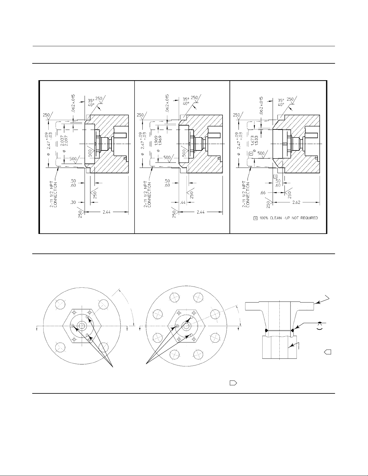
Flange Orientation
Orient the controller so that the case is level. See figure 4 for the proper sensor orientation for flange welding.
WARNING
To maintain code/standard compliance, weld fabrication must meet the requirements of ASME Section IX. Failures to meet
these requirement could result in personal injury and/or property damage.
WARNING
To maintain compliance with NACE MR0175, weld fabrication must meet the requirements of NACE MR0175, paragraph 5.3.
Failure to meet these requirements could result in personal injury and/or property damage.
www.Fisher.com
Page 2
L2, L2e, and L2sj Controller
April 2013
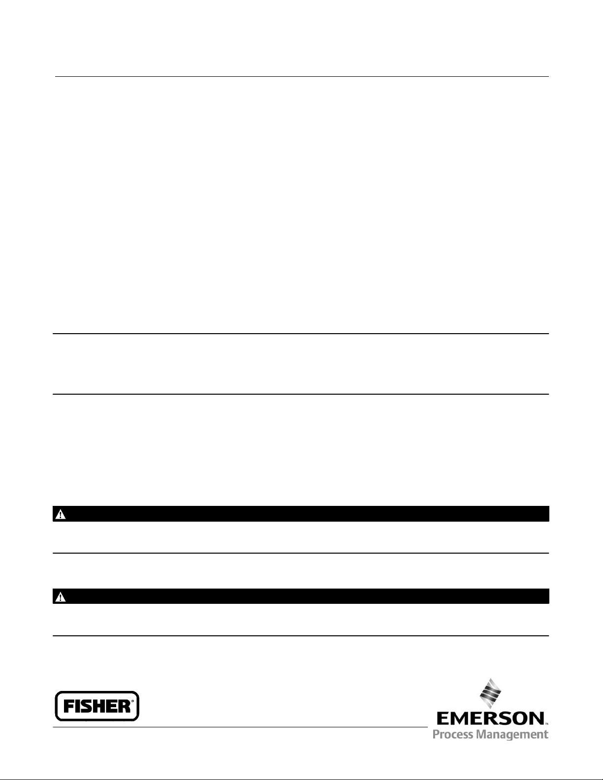
Figure 1. Typical Sensor Connection
Instruction Manual Supplement
D103277X012
CUT HERE TO
REMOVE THREAD
PREPARE SURFACE
FOR WELD
10C2006-A
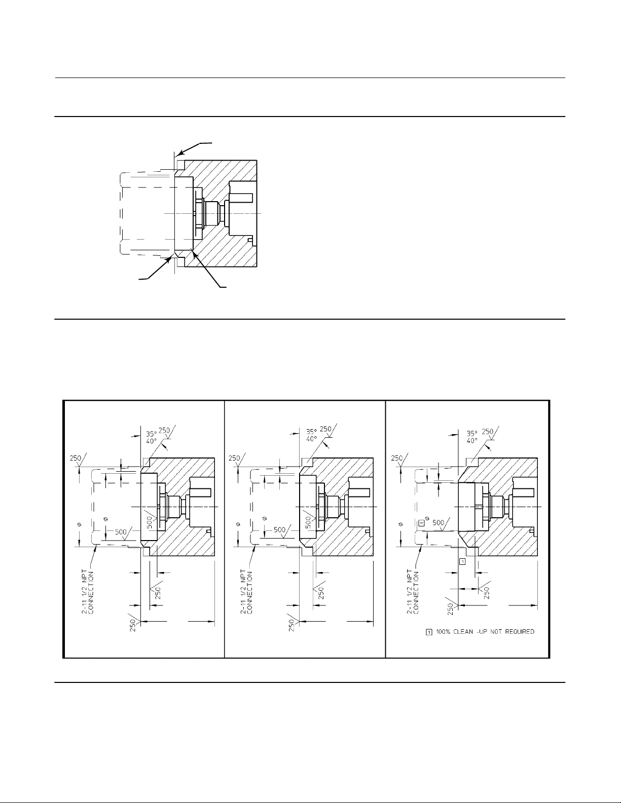
Figure 2. Sensor Connections (mm)
1.6 $ 0.4
51.7
53.3
* 0.8
62.7 ) 2.3
12.7
15.2
CONTROLLER
7.6
62 62
BORE AND MACHINE TO
GIVEN DIMENSIONS
1.6 $ 0.4
50.0
48.5
* 0.8
62.7 ) 2.3
12.7
15.2
CONTROLLER
11.2
37.4
62.7 ) 2.3
* 0.8
CONTROLLER
38.9
12.7
15.2
16.8
1.6 $ 0.4
66.5
NPS 2 ANSI SCHED 40
10C2006-A
NOTE:
SEE FIGURE 1 FOR A TYPICAL SENSOR CONNECTION
2
NPS 2 ANSI SCHED 80
NPS 2 ANSI SCHED XXS
Page 3
Instruction Manual Supplement
D103277X012
Figure 3. Sensor Connections (Inches)
L2, L2e, L2sj Controller
April 2013
CONTROLLER
NPS 2 ANSI SCHED 40
10C2006-A
NOTE:
SEE FIGURE 1 FOR A TYPICAL SENSOR CONNECTION
CONTROLLER
Figure 4. Sensor Orientation for Flange Mounting
45_ $2.5_
A
A
FLANGE ASSEMBLY
WITH 4 HOLE FLANGE
10C1996‐A
A
NOTE RELATION
OF TABS TO THE
BOLT PATTERN
NPS 2 ANSI SCHED 80
FLANGE ASSEMBLY
WITH 8 HOLE FLANGE
CONTROLLER
NPS 2 ANSI SCHED XXS
22.5_$2.5_
A
SECTION A‐A
CONNECTION USED FOR ORIENTATION
1
FLANGE
.12 max
O
.06
CONNECTION
1
3
Page 4

L2, L2e, and L2sj Controller
April 2013
Instruction Manual Supplement
D103277X012
Installation
1. Install a suitable flange gasket.
2. Insert the displacer end of the sensor into the tank connection. Position the sensor so it can be bolted to the tank
flange.
3. Complete the sensor flange to tank flange connection.
Refer to figure 5 for NPS 2X2 flange dimensions and figure 6 for NPS 2X4 flange dimensions for the L2 controller,
figure 7 for NPS 2X2 flange dimensions and figure 8 for NPS 2X4 flange dimensions for the L2e controller, and figure 9
for NPS 2X4 flange dimensions for the L2sj controller.
Related Documents
D Fisher L2 Liquid Level Controller Instruction Manual (D103032X012)
D Fisher L2e Electric Level Controller Instruction Manual (D103531X012)
D Fisher L2sj Low Emission Liquid Level Controller Instruction Manual (D103216X012)
4
Page 5

Instruction Manual Supplement
D103277X012
Figure 5. Fisher L2 Liquid Level Controller, NPS 2X2 Flange Dimensions (also see tables 1 and 2)
L2, L2e, L2sj Controller
April 2013
10C1997-A
Table 1. Fisher L2 Liquid Level Controller, NPS 2X2 Flange Dimensions (with one 6‐inch extension)
SCHEDULE 40 & 80 SCHEDULE XXS
PRESSURE RATING & TYPE
CL150 RF 312 217 566 307 222 561
CL300 RF 306 223 560 301 228 555
CL600 RF 296 232 550 291 237 545
CL150 RF 12.28 8.53 22.28 12.09 8.72 22.09
CL300 RF 12.03 8.78 22.03 11.84 8.97 21.84
CL600 RF 11.66 9.15 21.66 11.47 9.34 21.47
A B C A B C
mm
INCH
Table 2. Fisher L2 Controller - NPS 2X2 Flange Dimensions (with one 6‐inch extension)
SCHEDULE 40 & 80 SCHEDULE XXS
PRESSURE RATING & TYPE
CL600 RTJ 294 234 548 290 239 544
CL900/CL1500 RF 268 261 522 263 266 517
CL900/CL1500 RTJ 266 263 520 261 268 515
CL600 RTJ 11.59 9.22 21.59 11.41 9.41 21.41
CL900/CL1500 RF 10.53 10.28 20.53 10.34 10.47 20.34
CL900/CL1500 RTJ 10.47 10.34 20.47 10.28 10.53 20.28
A B C A B C
mm
INCH
5
Page 6

L2, L2e, and L2sj Controller
Instruction Manual Supplement
April 2013
Figure 6. Fisher L2 Liquid Level Controller, NPS 2X4 Flange Dimensions (also see tables 3 and 4)
D103277X012
10C2009‐A
Table 3. Fisher L2 Liquid Level Controller, NPS 2X4 Inch Flange Dimensions (with one 6‐inch extension)
SCHEDULE 40 & 80 SCHEDULE XXS
PRESSURE RATING & TYPE
CL150 RF 307 222 561 303 226 557
CL300 RF 296 232 550 291 237 545
CL600 RF 283 245 537 279 250 533
CL600 RTJ 282 247 536 277 252 531
CL150 RF 12.09 8.72 22.09 11.91 8.91 21.91
CL300 RF 11.66 9.15 21.66 11.47 9.34 21.47
CL600 RF 11.15 9.66 21.15 10.97 9.84 20.97
CL600 RTJ 11.09 9.72 21.09 10.91 9.91 20.91
A B C A B C
mm
INCH
Table 4. Fisher L2 Controller - NPS 2X4 Inch Flange Dimensions (with one 6‐inch extension)
SCHEDULE 40 & 80 SCHEDULE XXS
PRESSURE RATING & TYPE
CL900 RF 261 268 515 256 272 510
CL900 RTJ 260 269 514 256 274 509
CL1500 RF 252 277 506 246 282 500
CL1500 RTJ 250 279 504 245 284 499
CL900 RF 10.28 10.53 20.28 10.09 10.72 20.09
CL900 RTJ 10.22 10.59 20.22 10.03 10.78 20.03
CL1500 RF 9.91 10.91 19.91 9.69 11.12 19.69
CL1500 RTJ 9.84 10.97 19.84 9.66 11.16 19.66
A B C A B C
mm
INCH
6
Page 7

Instruction Manual Supplement
L2, L2e, L2sj Controller
D103277X012
Figure 7. Fisher L2e Electric Level Controller, NPS 2X2 Flange Dimensions (also see tables 5 and 6)
1
1
April 2013
1 DIMENSIONS WITH ONE 6-INCH EXTENSION
GG13007-A
Table 5. Fisher L2e Electric Level Controller, NPS 2X2 Flange Dimensions (with one 6‐inch extension)
SCHEDULE 40 & 80 SCHEDULE XXS
PRESSURE RATING & TYPE
CL150 RF 312 214 566 307 219 561
CL300 RF 306 220 560 301 225 555
CL600 RF 296 230 550 291 237 545
CL150 RF 12.28 8.43 22.28 12.09 8.62 22.09
CL300 RF 12.03 8.68 22.03 11.84 8.87 21.84
CL600 RF 11.66 9.05 21.66 11.47 9.24 21.47
A B C A B C
mm
INCH
Table 6. Fisher L2e Controller - NPS 2X2 Flange Dimensions (with one 6‐inch extension)
SCHEDULE 40 & 80 SCHEDULE XXS
PRESSURE RATING & TYPE
CL600 RTJ 294 232 548 290 236 544
CL900/CL1500 RF 268 259 522 263 263 517
CL900/CL1500 RTJ 266 260 520 261 265 515
CL600 RTJ 11.59 9.12 21.59 11.41 9.31 21.41
CL900/CL1500 RF 10.53 10.18 20.53 10.34 10.37 20.34
CL900/CL1500 RTJ 10.47 10.24 20.47 10.28 10.43 20.28
A B C A B C
mm
INCH
7
Page 8

L2, L2e, and L2sj Controller
Instruction Manual Supplement
April 2013
Figure 8. Fisher L2e Electric Level Controller, NPS 2X4 Flange Dimensions (also see tables 7 and 8)
1
1
D103277X012
1 DIMENSIONS WITH ONE 6-INCH EXTENSION
GG13008
Table 7. Fisher L2e Electric Level Controller, NPS 2X4 Inch Flange Dimensions (with one 6‐inch extension)
SCHEDULE 40 & 80 SCHEDULE XXS
PRESSURE RATING & TYPE
CL150 RF 307 219 561 303 224 557
CL300 RF 296 230 550 291 235 545
CL600 RF 283 243 537 279 247 533
CL600 RTJ 282 244 536 277 249 531
CL150 RF 12.09 8.62 22.09 11.91 8.81 21.91
CL300 RF 11.66 9.05 21.66 11.47 9.24 21.47
CL600 RF 11.15 9.56 21.15 10.97 9.74 20.97
CL600 RTJ 11.09 9.62 21.09 10.91 9.81 20.91
A B C A B C
mm
INCH
Table 8. Fisher L2e Controller - NPS 2X4 Inch Flange Dimensions (with one 6‐inch extension)
SCHEDULE 40 & 80 SCHEDULE XXS
PRESSURE RATING & TYPE
CL900 RF 261 265 515 256 270 510
CL900 RTJ 260 266 514 256 271 509
CL1500 RF 252 275 506 246 280 500
CL1500 RTJ 250 276 504 245 281 499
CL900 RF 10.28 10.43 20.28 10.09 10.62 20.09
CL900 RTJ 10.22 10.49 20.22 10.03 10.68 20.03
CL1500 RF 9.91 10.81 19.91 9.69 11.02 19.69
CL1500 RTJ 9.84 10.87 19.84 9.66 11.06 19.66
A B C A B C
mm
INCH
8
Page 9

Instruction Manual Supplement
L2, L2e, L2sj Controller
D103277X012
Figure 9. Fisher L2sj Liquid Level Controller, NPS 2X4 Flange Dimensions (also see tables 9 and 10)
April 2013
GE31927
Table 9. Fisher L2sj Liquid Level Controller, NPS 2X4 Inch Flange Dimensions (with 3‐inch extension)
SCHEDULE 40 & 80 SCHEDULE XXS
PRESSURE RATING & TYPE
CL150 RF 231 222 336 226 226 331
CL300 RF 220 232 325 215 237 320
CL600 RF 207 245 312 202 250 307
CL600 RTJ 206 247 310 201 252 306
CL150 RF 9.09 8.72 13.22 8.91 8.91 13.03
CL300 RF 8.66 9.15 12.78 8.47 9.34 12.59
CL600 RF 8.15 9.66 12.27 7.97 9.84 12.09
CL600 RTJ 8.09 9.72 12.22 7.91 9.91 12.03
A B C A B C
mm
INCH
Table 10. Fisher L2sj Controller - NPS 2X4 Inch Flange Dimensions (with 3‐inch extension)
SCHEDULE 40 & 80 SCHEDULE XXS
PRESSURE RATING & TYPE
CL900 RF 185 268 290 180 272 285
CL900 RTJ 183 269 288 179 274 284
CL1500 RF 176 277 280 170 282 275
CL1500 RTJ 174 279 279 169 284 274
CL900 RF 7.28 10.53 11.41 7.09 10.72 11.22
CL900 RTJ 7.22 10.59 11.34 7.03 10.78 11.16
CL1500 RF 6.91 10.91 11.03 6.69 11.12 10.82
CL1500 RTJ 6.84 10.97 10.97 6.66 11.16 10.78
A B C A B C
mm
INCH
9
Page 10

L2, L2e, and L2sj Controller
April 2013
Instruction Manual Supplement
D103277X012
Neither Emerson, Emerson Process Management, nor any of their affiliated entities assumes responsibility for the selection, use or maintenance of any product.
Responsibility for proper selection, use, and maintenance of any product remains solely with the purchaser and end user.
Fisher is a mark owned by one of the companies in the Emerson Process Management business division of Emerson Electric Co. Emerson Process
Management, Emerson, and the Emerson logo are trademarks and service marks of Emerson Electric Co. All other marks are the property of their respective
owners.
The contents of this publication are presented for informational purposes only, and while every effort has been made to ensure their accuracy, they are not
to be construed as warranties or guarantees, express or implied, regarding the products or services described herein or their use or applicability. All sales are
governed by our terms and conditions, which are available upon request. We reserve the right to modify or improve the designs or specifications of such
products at any time without notice.
Emerson Process Management
Marshalltown, Iowa 50158 USA
Sorocaba, 18087 Brazil
Chatham, Kent ME4 4QZ UK
Dubai, United Arab Emirates
Singapore 128461 Singapore
www.Fisher.com
10
E LLC 2007, 2013 Fisher Controls International. All rights reserved.
 Loading...