


Instruction Manual Supplement
D103405X012
L2, L2e, and L2sj Controller
April 2013
Dimensions for NPS 2 CL150 through 1500
Slip‐On Flange Connections
Supplement to Fisherr L2, L2e, and L2sj Level Controller
Instruction Manuals
This supplement contains dimensions for NPS 2 CL150 through 1500 slip‐on flange connections for L2, L2e, and L2sj
level controllers.
Refer to the Maintenance section of the appropriate instruction manual for instructions on removing the sensor from
the controller, and disassembly of the sensor connector.
Refer to the appropriate instruction manual for all other information regarding the L2, L2e, or L2sj level controller.
D L2 dimensions—refer to figure 2 and table 1
D L2e dimensions—refer to figure 3 and table 2
D L2sj dimensions—refer to figure 4 and table 3
www.Fisher.com
L2, L2e, and L2sj Controller
April 2013
Instruction Manual Supplement
D103405X012
Flange Orientation
Orient the controller so that the case is level. See figure 1 for the proper sensor orientation for flange welding.
WARNING
To maintain code/standard compliance, weld fabrication must meet the requirements of AS ME Section IX. Failure to meet
these requirement could result in personal injury and/or property damage.
WARNING
To maintain compliance with NACE MR0175, weld fabrication must meet the requirements of NACE MR0175, paragraph 5.3.
Failure to meet these requirements could result in personal injury and/or property damage.
Note
Slip-on flanges are not supplied with the L2, L2e, or L2sj level controller. Contact your Emerson Process Management sales office
for information on obtaining a slip-on flange construction.
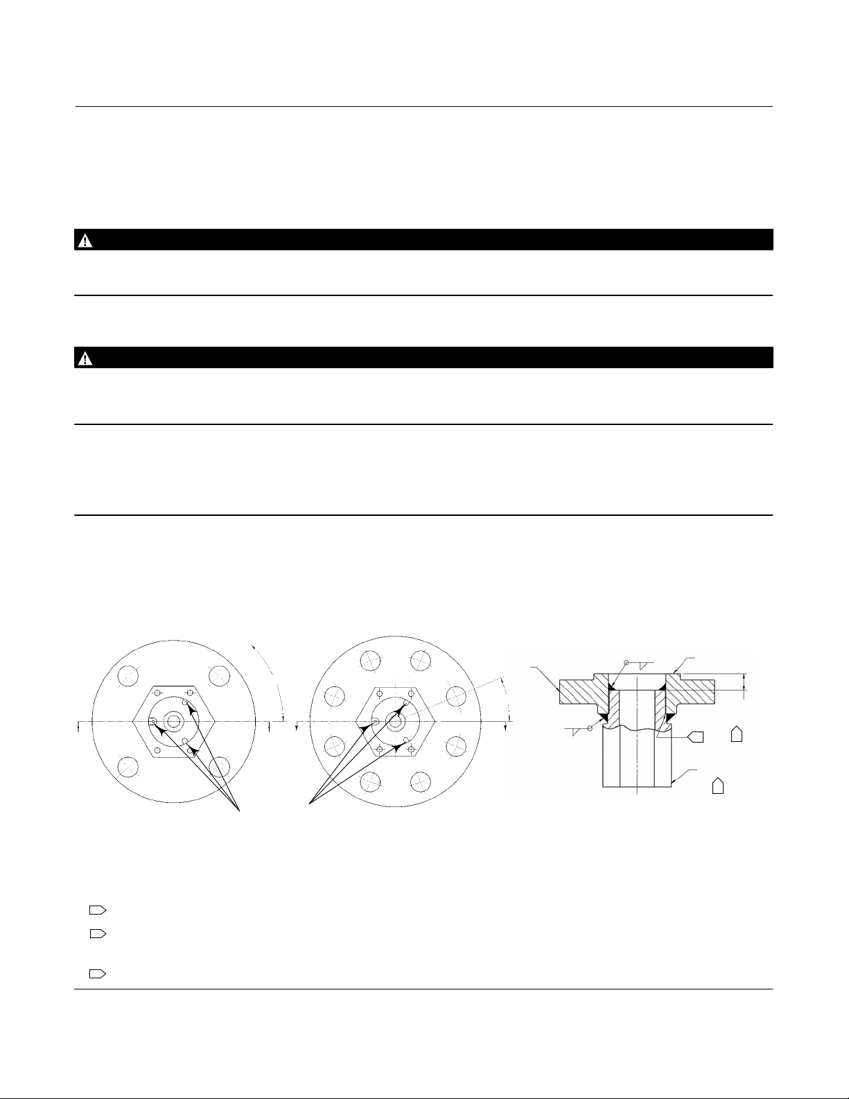
Figure 1. Sensor Orientation for Slip‐On Flange Mounting
45_ $2.5_
A
FLANGE ASSEMBLY
WITH 4 HOLE FLANGE
34B5013‐C
1
CONNECTION SHOULDER TO BOTTOM ON FLANGE HUB EXCEPT WHEN
END‐TO‐FLANGE FACE IS LESS THAN 8.64 mm (0.34 INCH)
2
DIMENSION ONLY APPLIES WHEN CONNECTION CAN BE INSERTED
SUCH THAT CONNECTION END‐TO‐FLANGE CONNECTION IS LESS THAN
8.64 mm (0.34 INCH)
CONNECTION USED FOR ORIENTATION
3
NOTE RELATION
OF TABS TO THE
BOLT PATTERN
A
A
FLANGE ASSEMBLY
WITH 8 HOLE FLANGE
FLANGE
22.5_$2.5_
A
0.63
OR HUB
WIDTH
0.25
SECTION A‐A
FLANGE FACE
8.64
(0.34)
2
1
CONNECTION
3
mm
(INCH)
2

Instruction Manual Supplement
D103405X012
Related Documents
D Bulletin 34.2:L2—Fisher L2 Liquid Level Controller (D103034X012)
D Fisher L2 Liquid Level Controller Instruction Manual (D103032X012)
D Bulletin 34.2:L2e—Fisher L2 Electric Level Controller (D103532X012)
D Fisher L2e Electric Level Controller Instruction Manual (D103531X012)
D Bulletin 34.2:L2sj—Fisher L2sj Low Emission Liquid Level Controller (D103229X012)
D Fisher L2sj Low Emission Liquid Level Controller Instruction Manual (D103216X012)
L2, L2e, and L2sj Controller
April 2013
3
 Loading...