

Page 1
Product Bulletin
i2P-100 Transducer
D103197X012
62.1:i2P-100
July 2014
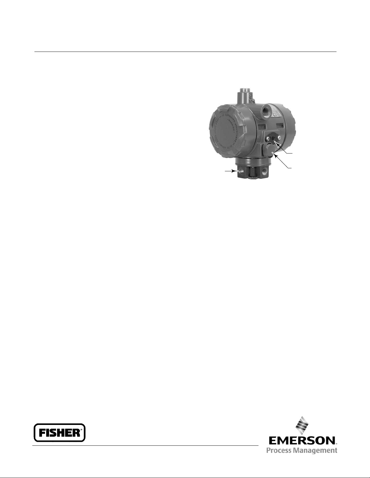
Fisherr i2P-100 Electro-Pneumatic Transducer
The Fisher i2P-100 electro-pneumatic transducer, uses
a converter module that converts a milliampere input
to a proportional pressure output. Both the current
input and pressure output range are user-configurable
in the field. The converter module uses small parts of
minimum mass, which are balanced symmetrically
around a pivot point at the center of the mass. This
balanced arrangement results in a high performance
instrument that reduces sensitivity to vibration.
An integral pneumatic relay provides the high capacity
necessary to drive pneumatic control valve/actuator
assemblies without additional boosters or positioners.
The transducer also provides stable, accurate
operation when its output is transmitted to small
volume chambers, such as a pneumatic positioner or
other pneumatic instrument. Reduced sensitivity to
vibration, combined with high capacity and first order
lag characteristics, make the i2P-100 transducer
suitable for direct mounting on control valve/actuator
combinations.
INTEGRAL
PNEUMATIC
RELAY
W8710
n High Output Capability and Rangeability— The
integral output relay volume of the transducer is
adequate to drive valve/actuator combinations
without requiring a positioner or volume booster.
Selectable user field-configurable dip switch setting
for output range of 0.14 to 2.3 bar (2 to 33 psi).
REPLACEABLE
FILTER WITH
REMOVABLE
ORIFICE
VENT
Features
n Approved for use with Natural Gas—The i2P-100 is
approved for use with natural gas as the pneumatic
supply.
n Low Pneumatic Supply Consumption—The
transducer has low pneumatic supply consumption
which lowers operating costs. Maximum steady
state consumption is less than the 6 SCFH
requirement set for the oil and gas industry by the
US Environmental Protection Agency (New Source
Performance Standards Subpart OOOO,
EPAHQQAR20100505).
n Single Sealed Device— The i2P-100 has been tested
in accordance with ANSI/ISA Standard 12.27.01
(Requirements for Process Sealing Between
Electrical Systems and Flammable or Combustible
Process Fluids) as a single sealed device.
n Split Range—Selectable user field-configurable
two-way split range, using either half of the
standard input signal.
n Corrosion Resistant—Separate housing
compartments isolate the electronics from the
pneumatic process. The electronics module is
encased in a rugged plastic shell which helps to
prevent damage to the electronics. The printed
wiring board and dip switches are conformal coated
to help prevent corrosion. Converter module coils
have corrosion resistant coating and all flexures are
gold plated to provide protection from hostile
environments.
n Tolerant of Dirty Supply Medium—Free-flow pilot
stage design and large internal air passages provide
excellent tolerance to dirty pneumatic supply, by
reducing the effects of contaminant buildup and
erosion. The removable primary orifice and
replaceable 5 micrometer filter are easy to remove
for service and maintenance.
www.Fisher.com
Page 2
Product Bulletin
62.1:i2P-100
July 2014
i2P-100 Transducer
D103197X012
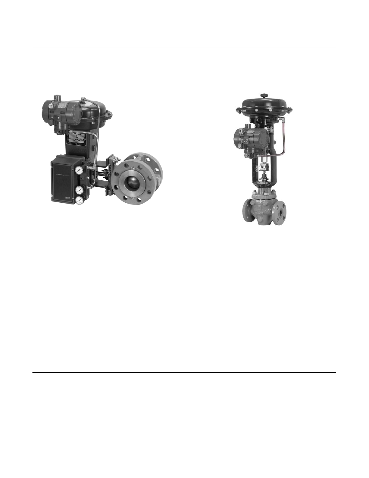
Figure 1. Fisher i2P-100 Electro-Pneumatic
Transducer Mounted on a Rotary Actuator
W8693-1
Figure 2. Fisher i2P-100 Electro-Pneumatic
Transducer Mounted on a Sliding-Stem Actuator
W8723-1
n Easy Maintenance—Modular electronics and
converter modules contained in separate housing
compartments, isolating the electronics from the
process, allow for easy replacement in the field for
reduced maintenance time and costs.
n Vibration Resistance—The transducer, used in a
standard valve/actuator mounted application,
exhibits an output shift of less than 1 percent of
span when tested to ISA S75.13.
Table of Contents
Features 1.....................................
Valve Stroking Time 2...........................
Specifications 3................................
Energy Responsible Tool 4.......................
Installation 6..................................
Ordering Information 6..........................
Valve Stroking Time
Figure 3 shows relative times for loading and
exhausting an actuator. Stroking time depends upon
the size of the actuator, travel, relay characteristics
and the magnitude and rate of change of the input
signal. If stroking time is critical, contact your Emerson
Process Management sales office.
2
Page 3

i2P-100 Transducer
D103197X012
Specifications
Product Bulletin
62.1:i2P-100
July 2014
Input Signal
Available as standard with 4-20 mA.
User configurable by dip switch for split ranging, see
table below.
Output Signal
Available as standard 0.2 to 1.0 bar (3 to 15 psig),
0.4 to 2.0 bar (6 to 30 psig), or 0.14 to 2.3 bar
(2 to 33 psig). User configurable by dip switch
selection and zero and span potentiometer
adjustment, see table below.
INPUT SIGNAL
4 to 20 mA DC
4 to 12 mA DC 0.2 to 1.0 3 to 15
12 to 20 mA DC 0.2 to 1.0 3 to 15
OUTPUT PRESSURE
Bar Psig
0.2 to 1.0 3 to 15
0.4 to 2.0 6 to 30
0.14 to 2.3 2 to 33
Equivalent Circuit
The i2P-100 equivalent circuit is a series circuit
consisting of a constant voltage drop (battery) of
approximately 4 VDC and a total resistance of 40
ohms. Input is shunted by two 6.8 V zener diodes (see
figure 4).
Supply Pressure
(1)
Recommended: 0.34 bar (5 psi) higher than upper
range limit of output signal
Maximum: 3.4 bar (50 psig)
Medium: Air or Natural Gas
Frequency Response: Gain is attenuated 3 dB at 3 Hz
with transducer output signal piped to a typical
instrument input
Temperature Effect: $0.14% per degrees Celsius
($0.075 per degrees Fahrenheit) of span
Supply Pressure Effect: 0.2% of full scale output span
per psi supply pressure change)
Vibration Effect: Less than 1% of full scale output span
when tested to ISA S75.13
Electromagnetic Compatibility
Meets EN 61326-1 (First Edition)
Immunity—Industrial locations per Table 2 of
EN 61326-1 Standard. Performance is
shown in table 1 below.
Emissions—Class A
ISM equipment rating: Group 1, Class A
Operating Ambient Temperature Limits
(1)
-40 to 85_C (-40 to +185_F)
Electrical Seal
Single sealed device per ANSI/ISA 12.27.01
Electrical Classification
Hazardous Area:
CSA — Intrinsically Safe, Explosion proof,
Type n, Dust‐Ignition proof
Maximum Steady-State Flow Rate
(2)(3)
Refer to tables 2 and 3
Maximum Output Air Capacity
(3)
8.04 m3/hr (300 scfh) at 1.4 bar (20 psig) supply
pressure
Performance
(4)
Reference Accuracy: ±1.0% of full scale output span;
includes combined effects of hysteresis, linearity, and
deadband
Independent Linearity: ±0.5% of full scale output span
Hysteresis: 0.4% of full scale output span
-continued-
FM— Intrinsically Safe, Explosion proof,
Type n, Non‐incendive, Dust‐Ignition proof
ATEX— Intrinsically Safe, Flameproof , Type n
IECEx— Intrinsically Safe, Flameproof, Type n
Refer to tables 4, 5, 6, and 7 for specific approval
information.
Electrical Housing:
When Remotely Vented No Remote Venting
CSA—Type 4X Encl.
FM— NEMA 4X
ATEX—IP66
IECEx—IP66
CSA—Type 3 Encl.
FM— NEMA 3
ATEX—IP64
IECEx—IP64
3
Page 4

Product Bulletin
62.1:i2P-100
July 2014
Specifications (continued)
i2P-100 Transducer
D103197X012
Other Classifications/Certifications
GOST‐R—Russian GOST‐R
INMETRO— National Institute of Metrology, Quality,
and Technology (Brazil)
KGS—Korea Gas Safety Corporation (South Korea)
NEPSI— National Supervision and Inspection Centre
for Explosion Protection and Safety of
Instrumentation (China)
RTN—Russian Rostekhnadzor
Contact your Emerson Process Management sales
office for classification/certification specific
information
Construction Materials
Housing:
J Low-Copper aluminum with
polyurethane paint
O-rings: Nitrile
Diaphragms: Nitrile
Adjustments
(5)
Zero and Span: Trim potentiometers (20 turn) for
zero and span adjustments are located under the
housing cap.
Switch: Allows input signal split range and
user-configurable 0.14 to 2.3 bar (2 to 33 psig)
output.
Connections
Supply and Output Pressure: 1/4 NPT internal
connection
Vent: 1/4 NPT internal
Electrical:
J Standard 1/2 NPT
Wire Size: 18 to 22 AWG
Mounting Position
J Actuator J pipestand or J surface
Approximate Weight
2.5 kg (5.5 lbs)
Options
J Output pressure gauge J M20 or PG13 conduit
adapter
NOTE: Specialized instrument terms are defined in ANSI/ISA Standard 51.1 - Process Instrument Terminology
1. The pressure and temperature limits in this document and any applicable standard or code limitation should not be exceeded.
2. Average flow rate determined at 12 mA and 0.6 bar (9 psig) output.
3. Normal m
4. Performance values are obtained using a transducer with a 4 to 20 mA DC input signal and a 0.2 to 1.0 bar (3 to 15 psig) output signal at an ambient temperature of 24_C (75_F).
5. For other ranges, zero and span adjustments needed.
3
/hour--Normal cubic meters per hour (0_C and 1.01325 bar, absolute). Scfh--Standard cubic feet per hour (60_F and 14.7 psig).
Energy Responsible Tool
The web based Energy Responsible Tool
provides calculations for estimating operating costs
and emissions for instrument air and natural gas in
tonnes of Equivalent Carbon Dioxide (Co2e).
Scan or click the QR code to calculate pneumatic
energy savings.
4
Page 5

i2P-100 Transducer
D103197X012
Table 1. EMC Summary Results—Immunity
Port Phenomenon Basic Standard Test Level
Electrostatic discharge (ESD) IEC 61000-4-2
Enclosure
Radiated EM field IEC 61000-4-3
Burst (fast transients) IEC 61000-4-4 1 kV A
I/O signal/control
Surge IEC 61000-4-5 1 kV (line to ground only, each) A
Conducted RF IEC 61000-4-6 150 kHz to 80 MHz at 3 Vrms A
Specification limit = ±1% of span
1. A=No degradation during testing. B = Temporary degradation during testing, but is self-recovering.
4kV Contact
8kV Air
80 to 1000 MHz @ 10V/m with 1 kHz AM at 80%
1400 to 2000 MHz @ 3V/m with 1 kHz AM at 80%
2000 to 2700 MHz @ 1V/m with 1 kHz AM at 80%
Product Bulletin
62.1:i2P-100
July 2014
Performance
Criteria
A
A
(1)
Figure 3. Output-Time Relationships
100
90
80
70
60
50
OUTPUT
40
30
20
(% OF i2P-100 OUTPUT SPAN)
10
0
0 102030405060708090100
A6815
LOADING
EXHAUSTING
TIME (%)
Figure 4. Equivalent Circuit
4 - 20 mA
6.8V 6.8V 4V
40 Ohm
Table 2. Maximum Steady-State Flow Rate (Air)
SUPPLY PRESSURE OUTPUT PRESSURE
Bar Psi Bar Psi m3/hr Scfh
0.2 - 1.0 3 - 15
1.4 20
0.2 3 0.04 1.5
0.62 9 0.06 2.0
1.0 15 0.07 2.6
0.4 - 2.0 6 - 30
2.4 35
0.4 6 0.05 1.7
1.2 18 0.08 2.9
2 30 0.12 4.1
0.1 - 2.3 2 - 33
2.6 38
1. Normal m3/hour - Normal cubic meters per hour (0C and 1.0135 bar, absolute).
Scfh - Standard cubic feet per hour (60F and 14.7psig).
0.1 2 0.04 1.5
1.2 17.5 0.08 2.9
2.3 33 0.12 4.3
STEADY STATE
FLOW RATE
Table 3. Maximum Steady-State Flow Rate
(Natural Gas)
SUPPLY PRESSURE OUTPUT PRESSURE
Bar Psi Bar Psi m3/hr Scfh
0.2 - 1.0 3 - 15
1.4 20
0.2 3 0.06 1.95
0.62 9 0.07 2.6
1.0 15 0.1 3.38
0.4 - 2.0 6 - 30
2.4 35
0.4 6 0.6 2.21
1.2 18 0.11 3.77
2 30 0.15 5.33
0.1 - 2.3 2 - 33
2.6 38
1. Normal m3/hour - Normal cubic meters per hour (0C and 1.0135 bar, absolute).
Scfh - Standard cubic feet per hour (60F and 14.7psig).
2. Natural gas steady state flow based on natural gas specific gravity of 0.6.
Flow decreases as specific gravity increases.
0.1 2 0.06 1.94
1.2 17.5 0.11 3.74
2.3 33 0.18 5.55
STEADY STATE
FLOW RATE
(1)
(1,2)
5
Page 6

Product Bulletin
62.1:i2P-100
July 2014
i2P-100 Transducer
D103197X012
Installation
Refer to figure 5 for location of standard mounting
holes in the housing. See figures 1 and 2 for typical
mounting configurations. Standard mounting
hardware is provided for mounting on the actuator, a
pipestand, or surface mount. Field wiring connections
are made to the terminal block accessible under the
housing cap, via the 1/2 NPT conduit connection.
Dimensions are shown in figures 5, 6, 7, and 8.
Figure 5. Dimensions
74.2
(2.92)
81.6
(3.21)
GE06439
(sheet 1 of 4)
67.8
(2.67)
33.3
(1.31)
(2.19)
58.7
(2.31)
36.3
(1.43)
34.7
(1.37)
(3.89)
1/4 18 NPT
SUPPLY CONNECTION
55.7
CONDUIT CONNECTION
98.7
1/4 18 NPT VENT
OR PIPE-A-WAY
Ordering Information
To determine what ordering information is required,
refer to the Specifications table. Carefully review the
description of each specification. Specify the desired
choice whenever there is a selection available. Also,
specify options that are applicable to the application.
1/2 14 NPT
103.9
(4.09)
CONNECTION
1/4 18 NPT
OUTPUT CONNECTION
67 (2.62) CAP
REMOVAL
CLEARANCE
75.2
(2.96)
22.3
(0.88)
22.9
(0.90)
33.3
(1.31)
33.3
(1.31)
1/4 18 NPT
OUTPUT CONNECTION
75.7
(2.98)
103.9
(4.09)
67 (2.62) CAP
REMOVAL
CLEARANCE
mm
(INCH)
6
Page 7

i2P-100 Transducer
D103197X012
Figure 6. Dimensions with Optional Fisher 67 Filter-Regulator (Yoke/Bracket Mounted)
Product Bulletin
62.1:i2P-100
July 2014
67 (2.62)
COVER REMOVAL
CLEARANCE
(BOTH COVERS)
GE06439
(sheet 2 of 4)
238.1
(9.37)
57.2
(2.25)
240
(9.45)
69.9
(2.75)
50.8
(2.00)
8.6
(0.34)
126.3
(4.97)
74.2
(2.92)
6.4
(0.2
5)
170.8
(6.72)
101.1
(3.98)
204.8
(8.06)
mm
(INCH)
7
Page 8

Product Bulletin
62.1:i2P-100
July 2014
Figure 7. Dimensions with Optional Fisher 67 Filter-Regulator (Surface/Wall Mounted)
146.1
(5.75)
146.1
(5.75)
i2P-100 Transducer
D103197X012
67 (2.62)
COVER REMOVAL
CLEARANCE
(BOTH COVERS)
GE06439
(sheet 3 of 4)
91.1
(3.59)
209.6
(8.25)
mm
(INCH)
8
Page 9

i2P-100 Transducer
D103197X012
Figure 8. Dimensions with Optional Fisher 67 Filter-Regulator (Pipestand Mounted)
Product Bulletin
62.1:i2P-100
July 2014
67 (2.62)
COVER REMOVAL
CLEARANCE
(BOTH COVERS)
GE06439
(sheet 4 of 4)
238.1
(9.37)
60.5
(2.38)
240
(9.55)
50.8
(2.00)
(2.92)
74.2
170.8
(6.72)
243.2
(9.58)
mm
(INCH)
9
Page 10

Product Bulletin
62.1:i2P-100
July 2014
Table 4. Hazardous Area Classifications—CSA (Canada)
Certification Body Certification Obtained Entity Rating Temperature Code Enclosure Rating
CSA
*When remotely vented.
Intrinsically Safe
Ex ia IIC T3/T4/T5 per drawing GE07471
Ex ia Intrinsically Safe
Class I, II, III Division 1 GP A,B,C,D,E,F,G
per drawing GE07471
Explosion Proof
Ex d IIC T5/T6
Class I, Division 1 GP, A,B,C,D T5
Type n
Ex nC IIC T5/T6
Class I, Division 2, GP A,B,C,D T5
Class II, Division 1 GP E,F,G T5
Class II, Division 2, GP F,G T5
Class III
Vmax = 30 VDC
Imax = 100 mA
Pi = 1.0 W
Ci = 0 uF
Li = 0 uH
- - -
- - -
- - - T5 (Tamb ≤ 85°C) CSA Type 4X Encl.*
T3 (Tamb ≤ 85°C)
T4 (Tamb ≤ 81°C)
T5 (Tamb ≤ 46°C)
T5 (Tamb ≤ 85°C)
T6 (Tamb ≤ 75°C)
T5 (Tamb ≤ 85°C)
T6 (Tamb ≤ 75°C)
Table 5. Hazardous Area Classifications—FM (United States)
Certification Body Certification Obtained Entity Rating Temperature Code Enclosure Rating
FM
*When remotely vented.
IS Intrinsically Safe
Class I, II, III Division 1 GP A,B,C,D,E,F,G
per drawing GE07470
Class I Zone 0 AEx ia IIC T3/T4/T5 per
drawing GE07470
XP Explosion Proof
Class I, Division 1, GP A,B,C,D T5/T6
Class I Zone 1 AEx d IIC T5/T6
NI Non-indendive
Class I, Division 2, GP A,B,C,D T5/T6
Type n
Class I, Zone 2 AExnC IIC T5/T6
DIP Dust-igntion proof
Class II, III Division 1, GP E,F,G T5/T6
S Suitable for Use
Class II, III Division 2, GP F,G T5/T6
Vmax = 30 VDC
Imax = 100 mA
Pi = 1.0 W
Ci = 0 uF
Li = 0 uH
- - -
T3 (Tamb ≤ 85°C)
T4 (Tamb ≤ 81°C)
T5 (Tamb ≤ 46°C)
T5 (Tamb ≤ 85°C)
T6 (Tamb ≤ 75°C)
i2P-100 Transducer
D103197X012
CSA Type 4X Encl.*
CSA Type 4X Encl.*
CSA Type 4X Encl.*
NEMA 4X*
NEMA 4X*
10
Page 11

Product Bulletin
i2P-100 Transducer
D103197X012
Table 6. Hazardous Area Classifications—ATEX
Certificate Certification Obtained Entity Rating Temperature Code Enclosure Rating
ATEX
*When remotely vented.
Intrinsically Safe
II 1 GD
Gas
Ex ia IIC T3/T4/T5
Dust
T95°C (Tamb ≤ 85°C)
Flameproof
II 2 G D
Gas
Ex d IIC T5/T6
Dust
T95°C (Tamb ≤ 85°C)
Type n
II 3 G D
Gas
Ex nC II T5/T6
Dust
T95°C (Tamb ≤ 85°C)
Ui = 30 VDC
Ii = 100 mA
Pi = 1.0 W
Ci = 0 nF
Li = 0 mH
- - -
- - -
T3 (Tamb ≤ 85°C)
T4 (Tamb ≤ 81°C)
T5 (Tamb ≤ 46°C)
T5 (Tamb ≤ 85°C)
T6 (Tamb ≤ 75°C)
T5 (Tamb ≤ 85°C)
T6 (Tamb ≤ 75°C)
62.1:i2P-100
July 2014
IP66*
IP66*
IP66*
Table 7. Hazardous Area Classifications—IECEx
Certificate Certification Obtained Entity Rating Temperature Code Enclosure Rating
IECEx
*When remotely vented.
Intrinsically Safe
Gas
Ex ia IIC T3/T4/T5
Flameproof
Gas
Ex d IIC T5/T6
Type n
Gas
Ex nC IIC T5/T6
Ui = 30 VDC
Ii = 100 mA
Pi = 1.0 W
Ci = 0 uF
Li = 0 uH
- - -
- - -
T3 (Tamb ≤ 85°C)
T4 (Tamb ≤ 81°C)
T5 (Tamb ≤ 46°C)
T5 (Tamb ≤ 85°C)
T6 (Tamb ≤ 75°C)
T5 (Tamb ≤ 85°C)
T6 (Tamb ≤ 75°C)
IP66*
IP66*
IP66*
11
Page 12

Product Bulletin
62.1:i2P-100
July 2014
i2P-100 Transducer
D103197X012
Scan or click the
QR code to find out
more about the
i2P-100 transducer.
Neither Emerson, Emerson Process Management, nor any of their affiliated entities assumes responsibility for the selection, use or maintenance
of any product. Responsibility for proper selection, use, and maintenance of any product remains solely with the purchaser and end user.
Fisher is a mark owned by one of the companies in the Emerson Process Management business unit of Emerson Electric Co. Emerson Process Management,
Emerson, and the Emerson logo are trademarks and service marks of Emerson Electric Co. All other marks are the property of their respective owners.
The contents of this publication are presented for informational purposes only, and while every effort has been made to ensure their accuracy, they are not
to be construed as warranties or guarantees, express or implied, regarding the products or services described herein or their use or applicability. All sales are
governed by our terms and conditions, which are available upon request. We reserve the right to modify or improve the designs or specifications of such
products at any time without notice.
Emerson Process Management
Marshalltown, Iowa 50158 USA
Sorocaba, 18087 Brazil
Chatham, Kent ME4 4QZ UK
Dubai, United Arab Emirates
Singapore 128461 Singapore
www.Fisher.com
E 2004, 2014 Fisher Controls International LLC. All rights reserved.
12
 Loading...