

Emerson INDULGE SERIES, F-HC2215, F-HC1100, F-GN1100, F-HC2200 Installation, Care & Use Manual
...Page 1

Instant Hot Water Dispenser
Owner’s Manual
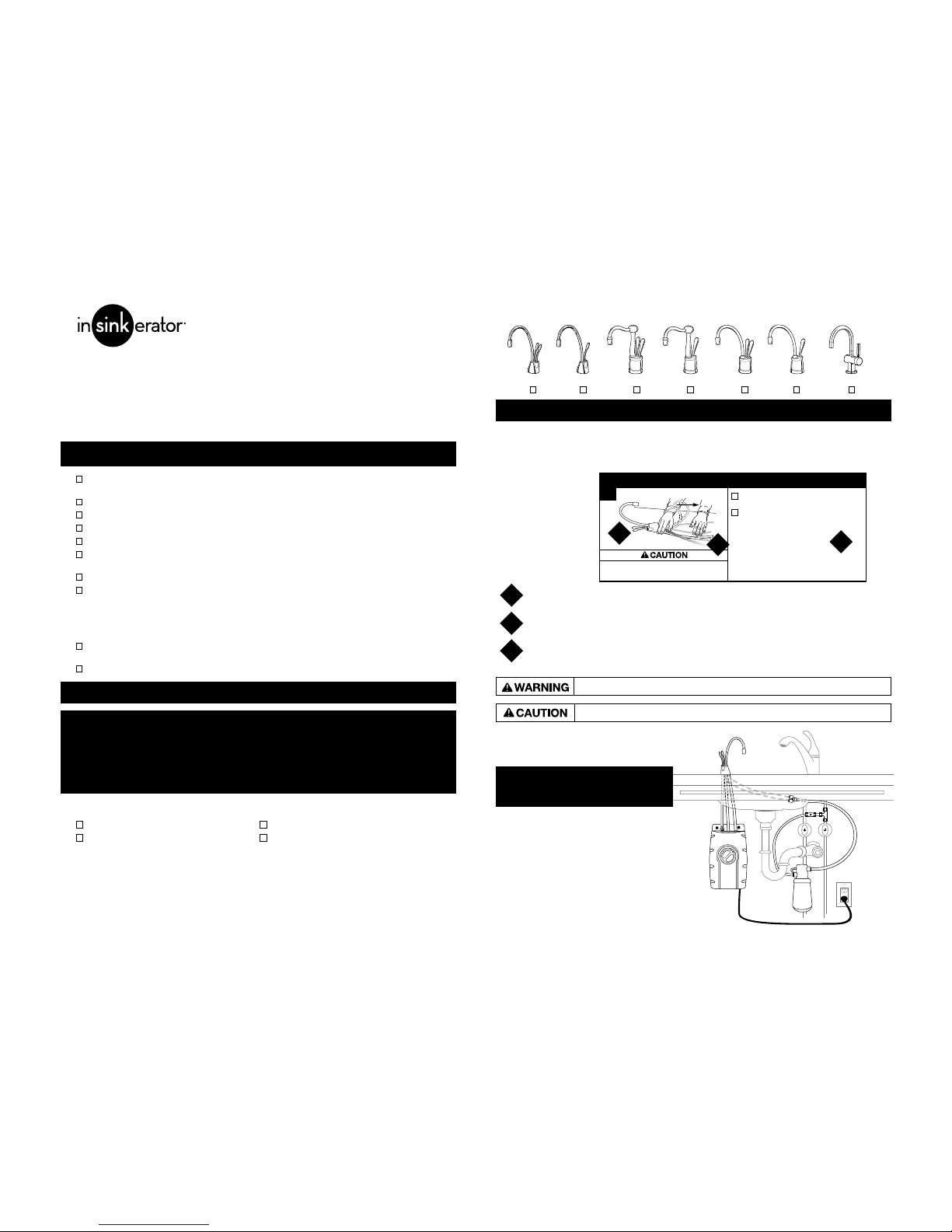
CONTEMPORARY
ANTIQUE
TUSCAN
MODERN
Installation, Care & Use
Instalación, cuidado y uso
Installation, soin et utilisation
SST-FLTR
GN/HC1100
GN/HC2200
GN/HC2215
H/HC3300
The Emerson logo is a trademark and
service mark of Emerson Electric Co.
© 2011 InSinkErator, a division of
Printed in USA Emerson Electric Co. All Rights Reserved.
InSinkErator may make improvements and/or
changes in the specifications at any time, in its sole
discretion, without notice or obligation and further
reserves the right to change or discontinue models.
1.800.558.5700
www.insinkerator.com
44463 REV A
Page 2
HOW TO USE THIS INSTRUCTION MANUAL
Provides a step-by-step narrative describing the installation step, with check boxes
that can be marked as you progress through the installation.
Contains simple illustrations that provide visual instruction to support the narrative.
CAUTIONS and WARNINGS that will require your attention during the step.
These instructions are separated into main sections, indicated by numbers, and subsections,
indicated by capital letters. The manual is setup this way to allow you to take a break at any
point after completing a section or subsection without affecting the installation process.
What you’ll see in the
instruction manual:
1
2
3
Identify the model of your instant hot water dispenser and record it here:________________
A
Property Damage: Do not pinch or break copper
tubing. Do not distort the last 1 inch of tubing.
INSTALLING THE FAUCET
Unpack dispenser components.
On a firm, flat surface, care
fully
straighten the copper tubing.
1
2
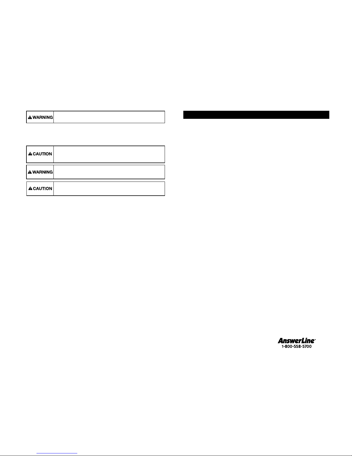
A potentially hazardous situation, which, if not avoided, could result in death or serious injury.
A potentially hazardous situation, which, if not avoided, may result in minor or moderate injury.
3
We are delighted that you have chosen the InSinkErator® Instant Hot Water Dispenser
to be a part of your home. This unique appliance will save you time and effort in the kitchen,
and you’ll enjoy discovering new uses for it each day. That’s exactly why millions of people are
now using an InSinkErator Instant Hot Water Dispenser.
We are confident that by following our step-by-step instructions, you’ll soon be enjoying the
convenience of instant hot water.
For your satisfaction and safety, read all instructions, cautions and warnings before installing or using this instant
hot water dispenser.
This particular unit is not intended for commercial use.
Make sure that all electrical wiring and connections conform to local codes.
A standard 115-volt grounded electrical outlet is required under the sink for the dispenser’s electrical power.
The wall outlet powering your dispenser must have power supplied to it continuously.
This outlet must be fused and should not be controlled by the same wall switch that operates the disposer, unless
you have a SinkTop Switch
™
from InSinkErator®.
It is recommended that a dedicated control valve be installed on the cold water line supplying water to this system.
If you suspect elevated levels of chlorine in your water, or your water has a rusty appearance before the installation
of this unit, it is recommended to use our water filtration system.
This product contains stainless steel. The manufacturer cannot guarantee against rusty water because of the
number of factors that are involved beyond the manufacturer’s control. However, the sudden appearance of rusty
water discharged from the hot water dispenser may indicate the need for service or replacement of this product.
The use of a water filter should NOT result in the water pressure to drop below 30 psi (207kPa). If it does, this will
prevent your unit from operating properly.
Moving parts inside the tank causing a rattling noise is normal.
WHAT YOU SHOULD KNOW BEFORE YOU BEGIN
QPhillips and flat blade screwdrivers
QPencil
QTape measure
QLevel
Equipment You May Need:
Equipment Required:
QDrill
QT-fitting
QDedicated control valve
QAdjustable wrench
Anchors for drywall
Hole saw
Basin wrench
Hole punch
If you intend to use the sprayer hole in your sink for your dispenser, you may need a basin wrench and a
1/8" plug or a 1/4" cap (not supplied) for the faucet spray hose line. See Step 1-B.
If you need to cut a mounting hole in your stainless steel sink, you may need a 1
1
⁄4" - 11⁄2" hole saw made
for cutting stainless steel or a hole punch. Consult a professional if you are drilling into a surface other
than stainless steel.
WHAT YOU NEED TO GET STARTED
F-HC3300/F-H3300F-HC1100 F-GN1100
F-GN2215F-HC2215
F-GN2200
F-HC2200
OVERVIEW OF A
COMPLETED SETUP
2 3
Page 3
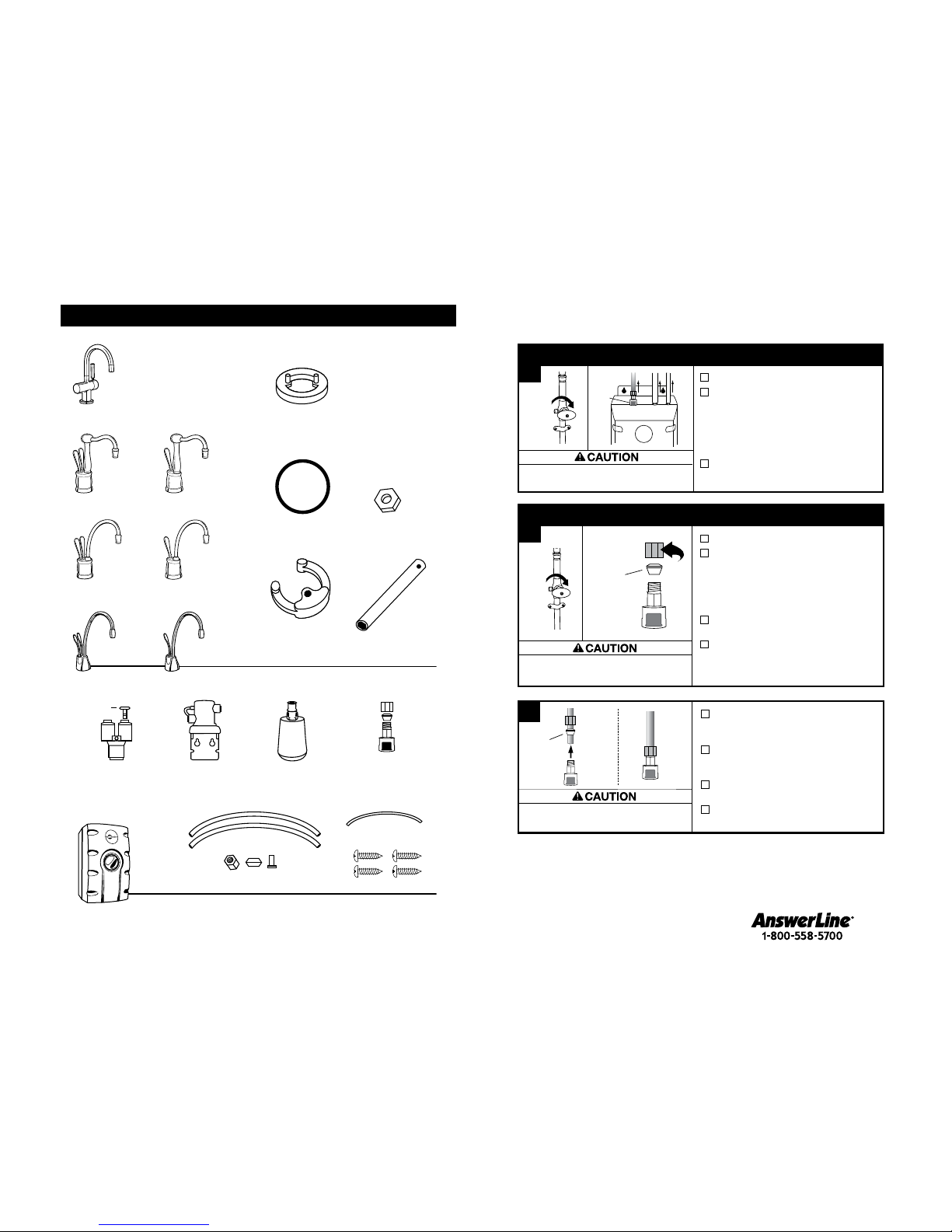
COMPONENTS IN THIS PACKAGE
SST-FLTR
Filter Head
3/8" Tubes ( 2)
6" Filter
Discharge Tube
Filter Cartridge
Brass Nut/Ferrule/
Tube Insert
F-HC1100 F-GN1100
F-HC2215 F-GN2215
F-HC2200 F-GN2200
Semi-circular
Mounting Plate
Rubber O-Ring
Hex Nut
Brass Seat
(HC3300, H3300)
Hex Tool
Snap-Connect
Fitting (3 pieces)
3/4" Screws (4)
Y-Quick Connector
F-H3300
F-HC3300
Plug (1)
4
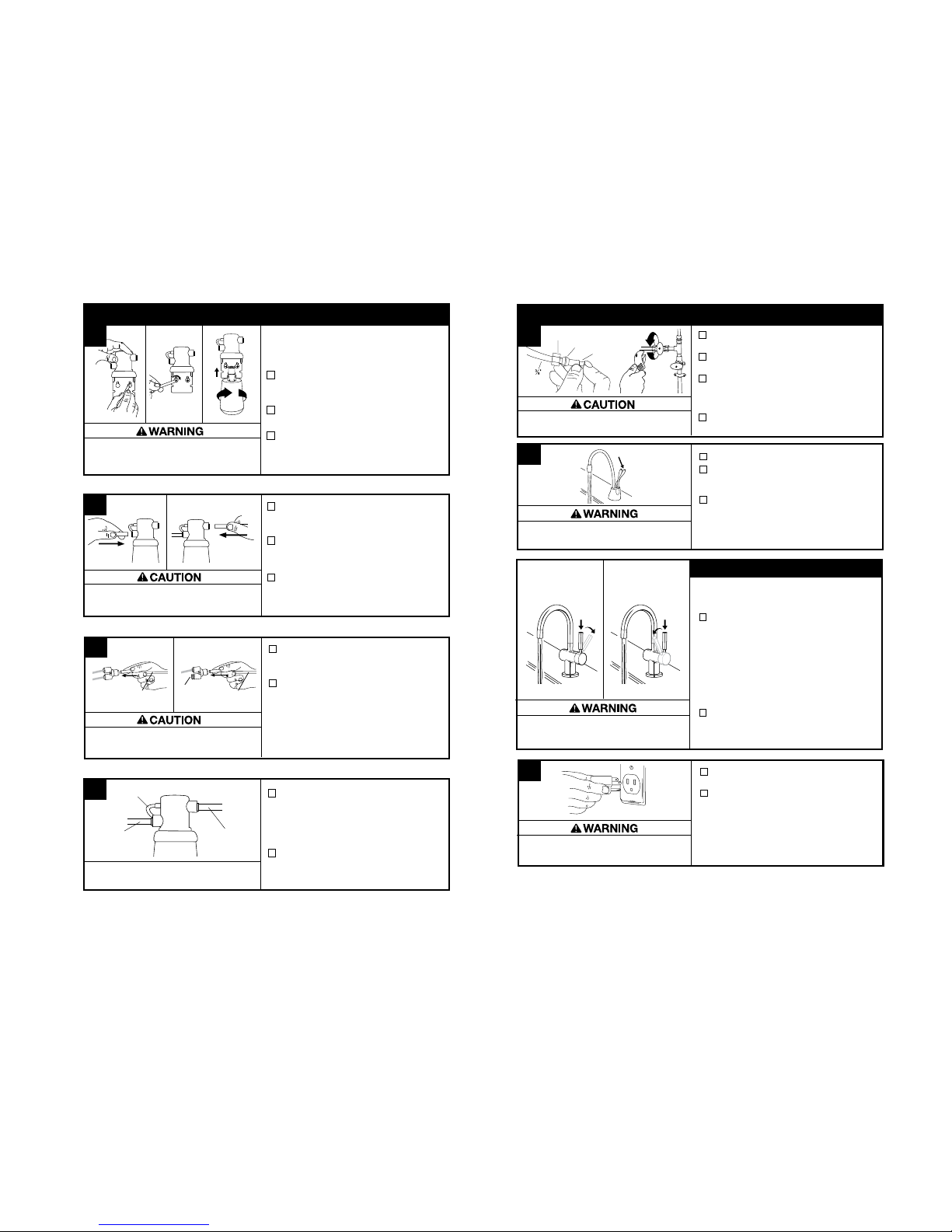
B
Turn off water supply.
At tank top, depress release ring or
gray release tab into quick-connect
fitting securing blue or copper 1/4"
tube and gently pull line off tank
fitting. Pull white 7/16" tube and
clear 5/16" tube off fittings.
If not already equipped, the included
snap-connect fitting must be installed.
To install snap-connect fitting,
unscrew brass mounting nut and
remove snap-connect fitting, brass
ferrule and nut.
A
Slide brass nut and plastic ferrule
onto the 1/4" blue or copper tube
running from the faucet.
Insert blue or copper tube into snap-
connect fitting and tighten brass nut
with a wrench, 1 to 2 turns clockwise.
You may elect to use existing tank
mounting bracket.
Skip to Page 9, Steps 3-4 for
complete installation instructions.
A
Turn off water supply.
Remove tubes from tank: At tank
top, depress gray release tab into
quick-connect fitting securing blue
or copper 1/4" tube and gently pull
line out of fitting. Pull white 7/16"
tube and clear 5/16" tube off fittings.
Remove existing faucet and continue
to page 6.
Blue Tube
Property Damage:
Do not over tighten brass nut.
Property Damage: Do not pinch or break copper
tubing. Do not distort the last 1 inch of tubing.
Property Damage: Unplug tank
before disconnecting tubing.
IF INSTALLING ONLY NEW TANK
Release
Tab
1/4"
blue
7/16"
white
5/16"
clear
Check
orientation
of ferrule
Make note of
orientation
of ferrule
IF INSTALLING ONLY NEW FAUCET
5
If installing BOTH new faucet and new tank, skip to page 6.
Page 4
Property Damage: Do not pinch or break copper
tubing. Do not distort the last 1 inch of tubing.
From under the sink, place the
semi-circular mounting plate onto
the threaded stud.
Place hex nut onto the threaded stud.
Ensure faucet head is at desired angle.
Insert screwdriver into hole on side of
hex tool (creating a “T”), and use tool
to tighten nut and secure faucet.
2
Semi-circular mounting plate should
encircle all descending tubes and
extend beyond sink hole when tight.
Ensure that the black O-ring is
properly seated in the base of the
dispenser head (the groove on the
underside of the dispenser).
Feed tubes down through the hole
in the sink or countertop until the
base is at rest on the sink or
countertop surface.
Unpack dispenser components.
On a firm, flat surface, carefully
straighten the copper tubing.
To ease feeding of tubes through hole,
first insert blue tube with quick-connect
attachment and then insert the remaining tubes.
B
A
C
D
Make sure to use rubber O-ring
to ensure proper seal.
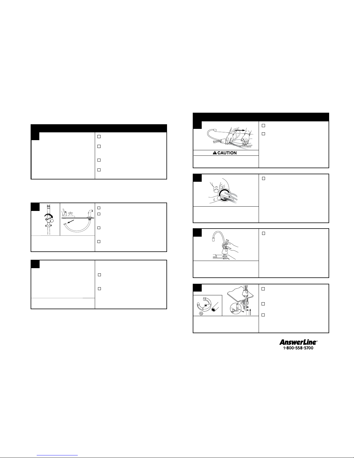
INSTALLING THE FAUCET - 1100/2200
The wall outlet for your dispenser must have power supplied to it continuously
and must be fused. It should not be controlled by the same wall switch
that operates your disposer, unless using an InSinkErator SinkTop Switch
TM
.
PREPARATION
START HERE
PROPER INSTALLATION SHOULD TAKE ABOUT 2-4 HOURS
Identify locations for the dispenser
faucet, tank and filter.
Check to make sure there is proper
clearance for dispenser handles to
be fully opened.
Check to make sure counter is 3"
thick or less.
Make sure there is a grounded
electrical outlet under the sink.
Turn off water supply.
If using the sink sprayer hose hole,
remove nut that connects sprayer
hose at bottom of faucet.
Using adjustable wrench, remove nut
connecting sprayer washer flange in
sprayer hole.
Plug hose opening with either a 1/8"
plug or a 1/4" cap (not supplied).
1
A
B
If you have to drill through sink or
countertop, you may need to rent or purchase
the appropriate tools.
Consult a professional before drilling into
a surface other than stainless steel.
C
What if you don’t have a sprayer hole or
don’t want to use it?
Many homeowners replace the soap
dispenser in their sink with an instant
hot water dispenser.
If drilling a hole into a stainless steel
sink or counter top, you can cut a
mounting hole for the dispenser with a
hole saw for stainless steel, or you can
use a hole punch.
Required Hole Size
F-HC1100 ................2
5
⁄8"
F-GN1100 ................3
1
⁄4"
F-HC2200 ................2
7
⁄8"
F-GN2200 ................3
1
⁄2"
F-HC2215 ................2
7
⁄8"
F-GN2215 ................3
1
⁄2"
F-HC3300 ................2
1
⁄2"
F-H3300 ...................2
1
⁄2"
Required minimum from
center of hole to wall
Maximum counter thickness is 3".
F-HC1100 ................1
3
⁄8" - 11⁄2"
F-GN1100 ................1
1
⁄4" - 11⁄2"
F-HC2200 ................1
3
⁄8" - 11⁄2"
F-GN2200 ................1
1
⁄4" - 11⁄2"
F-HC2215 ................1
3
⁄8" - 11⁄2"
F-GN2215 ................1
1
⁄4" - 11⁄2"
F-HC3300 ................1
3
⁄8" - 11⁄2"
F-H3300 ...................1
3
⁄8" - 11⁄2"
6 7
An assistant may be needed to
hold the dispenser head in place while
securing the dispenser.
Page 5
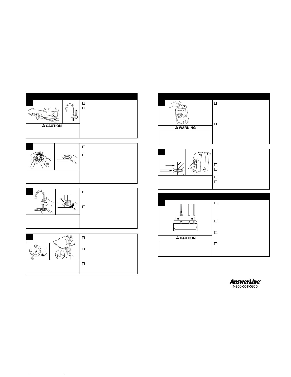
A
Select a spot under the sink to mount
tank vertically within reach of both
plumbing and electrical connections.
The tank should be within 16" or less
of faucet water lines and within 30"
or less of a standard grounded outlet.
While holding tank in place on
the spot selected for installation,
use a pencil to mark locations for
2 hanging screws.
Property Damage: Tank must be located
within 16" of faucet and within 30" or less
of a standard grounded outlet. DO NOT
extend plumbing or electrical lines.
3
Tank must be
mounted level
to ensure
proper operation.
Mount tank vertically in an area that allows clear-
ance on the underside of the tank for drainage, if
necessary.
DO NOT over tighten screws.
Pre-drill 1/8" pilot holes at marks.
Turn screws into pre-drilled holes,
leaving 1/4" exposed.
Hang the tank on the screws.
Tighten the screws with only
1/2 turn clockwise.
B
Screws provided are for use in wood
studs or cabinets only. Use wall anchors
(not supplied) for installation into drywall.
Leave 1/4" for
hanging tank.
Without depressing the gray button,
place the snap-connect fitting at
the end of the blue or copper 1/4"
tube onto the left fitting on the tank,
pushing until it clicks into place. (1)
Slip the flexible white 7/16" tube
over barbed steel fitting and slide
down approximately 1/2". (2)
Slip the clear 5/16" tube over the
smooth plastic fitting and slide down
approximately 1/2". (3)
Check for pinched or crimped tubes.
4
A
Property Damage: Pinched or blocked water lines
may cause damage to the dispenser tank. Check
to make sure tubes are connected properly and
are pushed down as far as possible.
Hose clamps are not needed for any
of the connections.
(1) (2) (3)
MOUNTING THE TANK
CONNECTING FAUCET TO TANK
Property Damage: Do not pinch or break tubing.
Do not distort the last 1 inch of tubing.
From under the sink, place the
semi-circular mounting plate onto
the threaded stud.
Place hex nut onto the threaded
stud. Ensure dispenser handle is on
preferred side and that faucet head
is at desired angle.
Insert screwdriver into hole on side
of hex tool (creating a “T”), and use
tool to tighten nut and secure faucet.
2
Semi-circular mounting plate should
encircle all descending tubes and
extend beyond sink hole when tight.
Insert rubber O-ring into groove on
brass seat.
Place brass seat, O-ring side down,
over hole in sink or countertop.
Holding brass seat in place, feed
tubes down through the hole in sink
or countertop until base touches
brass seat.
Rotate brass seat until the two
retaining studs fit into the holes on
the faucet base and base sits firmly
on brass seat.
Unpack dispenser components.
The recommended installation for
this faucet is dispenser handle on
the right.
The unique design allows the
handle to be fully functional when
placed to the right or left of faucet.
Determine preferred handle
placement before installing.
To ease feeding of tubes through hole, first
insert blue tube with quick-connect attachment
and then insert the remaining tubes.
B
A
C
D
Wetting O-ring with water prior to
inserting into brass seat helps hold
ring in place during installation.
INSTALLING THE FAUCET - 3300
8 9
Page 6
C
Scalding Hazard: The faucet dispenses near-boiling
(212ºF) water which can instantly cause scalds or
burns. Use care when operating this appliance.
Property Damage: Join remaining tube
to cold water supply only.
Turn on the water supply.
Depress the dispenser’s HOT handle and hold it
until water flows from the spout (approximately
1 to 2 minutes).
Run the water for at least 2 minutes to flush
lines (both the hot and cold handles
independently if applicable).
Note: See box below for special instructions on
operation of InDulge
™
Modern faucets.
B
A
Featuring OptiPush™ hot side activation with
automatic shut off and cool side Stay-On
™
, which
keeps the faucet open when dispensing cool water.
HC3300: To dispense instant hot water, first
press down on the faucet handle and then
push the handle backward in the direction of
the red indicator on the top of the handle.
To dispense cool water, first press down on
the faucet handle and then pull the handle
forward in the direction of the blue indicator
on the handle.
Featuring OptiPush
™
hot side activation with
automatic shut off.
H3300: To dispense instant hot water, first
press down on the faucet handle and then
push the handle backward in the direction of
the red indicator on the top of the handle.
6
Brass Nut
Ferrule
Brass Insert
Plastic
tube
Install a T-fitting (not included) onto the cold
water supply line.
Install dedicated water control valve with 3/8"
compression fitting.
At the end of the white 3/8" tube from the filter
or quick-connector, slide the supplied brass nut
and ferrule over the tube and then push in the
brass tube insert.
Insert the white 3/8" tube into the 3/8"
compression fitting and tighten.
If the water coming from the faucet is not hot 15 minutes after the unit has been
plugged in – or for other issues related to the operation of your instant hot water
dispenser – refer to the “Troubleshooting” section on Page 16.
FINAL WATER CONNECTION
C
Check all connections to ensure they are tight
and that there are no leaks.
Plug in instant hot water tank.
Water will be cold at first.
Allow 12-15 minutes for water to reach
target temperature.
Gurgling or hissing is normal during the
initial heating cycle.
Property Damage: A standard grounded outlet within
30” of the dispenser is required under the sink. Do not
use an extension cord set with the dispenser.
Operating Instructions for InDulgeTM Modern Faucets
Dispensing Hot Water
(HC3300, H3300)
Dispensing Cool Water
(HC3300)
Scalding Hazard: The faucet dispenses near-boiling
(212ºF) water which can instantly cause scalds or
burns. Use care when operating this appliance.
Property Damage: Do not extend the lines farther
than the 16” provided. Ensure tube(s) and “Y”
connector are securely fit.
Personal Injury: Do not locate filter above an outlet or other
electrical device. Install head and bracket so that connections
require no stretching, kinking or pinching of tubing.
It is normal for approximately 2 oz. of water to
discharge when filter is removed.
Property Damage: Tube runs need to form to the cabinet’s
contours to allow storage space with no sharp bends. Tubes
need clean, perpendicular, burr-free cuts to ensure a true fit.
A
Determine length of tubing required,
then cut to length making sure the cut
is perpendicular and burr-free.
Insert a white 3/8" tube into inlet side
of filter head until it stops.
Press in again to ensure a secure fit.
Insert the other white 3/8" tube into
outlet side of filter head until it stops.
Press in again to ensure a secure fit.
Mark hole locations for filter head
and bracket in a spot that allows
for filter replacement.
Drill 1/8" starter holes and attach bracket
to wall with wood screws, turning until snug.
Remove red filter cap, insert filter
cartridge into filter head and twist
clockwise until “LOCK” arrow on the
filter aligns with arrow on bracket.
To redirect filter replacement water
discharge, place 6" clear tube over
vent hole on the left side of filter head.
Note: 3/8" fitting is required to make
connection to water supply.
Connect remaining white 3/8" tube to
incoming water supply line.
(See Step 6.)
Insert the copper tubes(s) from the
dispenser into “Y” quick-connector
using the plug for hot-only models.
Connect the white 3/8" tube from
the right outlet on the filter head into
the quick-connect fitting until it stops.
Press in again to ensure a secure fit.
from water
supply line
to dispenser
To remove tube(s) or plug from quick-connector,
depress the release ring and gently pull away.
From filter or
water supply line
Plug
D
5
INSTALLING FILTRATION SYSTEM
Screws provided are for use in wood
studs or cabinets only. Use wall anchors
(not supplied) for installation into drywall.
B
From water
supply line
Discharge tube
To dispenser
10 11
From filter or
water supply line
HC1100, HC2200,
HC2215
GN1100, GN2200, GN2215,
HC3300, H3300
Page 7
Electric Shock Hazard: Using an ungrounded or improperly connected
appliance can result in serious injury or death from electrical shock.
Property Damage: To avoid water damage, replace any loose or split tubing.
Periodically inspect the unit for any signs of leakage and immediately remove from service any unit suspected of leaking.
Personal Injury: This tank is a non-pressurized tank. DO NOT modify this system.
DO NOT close vent tube or connect other type dispensers or valves to the tank. Use
only the InSinkErator dispenser faucet supplied. Use only parts provided. Contact an
authorized InSinkErator Service agent for repairs or replacement components.
This appliance must be grounded. This instant hot water dispenser is equipped with a cord that has a
grounding conductor and a grounding pin. The plug must be connected to an appropriate outlet that is properly
installed and grounded in accordance with all local codes and ordinances. Do not modify the plug provided
with the appliance – if it will not fit the outlet, have a proper outlet installed by a qualified electrician. Check
with a qualified electrician or serviceman if you are in doubt as to whether the instant hot water dispenser is
properly grounded.
Fire Hazard: To minimize possibility of fire, DO NOT store flammable items such as
rags, paper or aerosol cans near the tank. DO NOT store or use gasoline or other
flammable vapors and liquids in the vicinity of this or any other appliance.
An instant hot water dispenser, like any water heater, has a limited life and will eventually fail.
To avoid possible property damage and personal injury, this instant hot water dispenser should
be regularly examined for leakage and/or corrosion and replaced when necessary. A drain pan,
plumbed to an appropriate drain or outfitted with a leak detector, should be used in those
applications where any leakage could cause property damage. To check for corrosion,
examine the appearance of the dispensed water in a clear glass once every three (3) months.
If there is any discoloration or rusty appearance, unplug and drain unit as described in the
Seasonal Storage/Drainage section on page 14 of this manual. If the water discoloration
remains after draining and refilling unit, discontinue use and contact an authorized InSinkErator
service agent.
12
This warranty is provided by InSinkErator, a division of Emerson Electric Co., (“InSinkErator” or “Manufacturer” or “we” or “our” or
“us”) to the original consumer owner of the InSinkErator product with which this warranty is provided (the “InSinkErator Product”),
and any subsequent owner of the residence in which the Product was originally installed (“Customer” or “you” or “your”).
InSinkErator warrants to Customer that your InSinkErator Product will be free from defects in materials and workmanship, subject
to the exclusions described below, for the “Warranty Period”, commencing on the later of: (a) the date your InSinkErator Product is
originally installed, (b) the date of purchase, or (c) the date of manufacture as identified by your InSinkErator Product serial number.
You will be required to show written documentation supporting (a) or (b). If you are unable to provide documentation supporting
either (a) or (b), the Warranty Period commencement date will be determined by Manufacturer, in its sole and absolute discretion,
based upon your InSinkErator Product serial number.
What is Covered
This warranty covers defects in materials or workmanship, subject to the exclusions below, in InSinkErator Products used by a consumer
Customer for residential use only, and includes all replacement parts and labor costs. YOUR SOLE AND EXCLUSIVE REMEDY
UNDER THIS LIMITED WARRANTY SHALL BE LIMITED TO REPAIR OR REPLACEMENT OF THE INSINKERATOR PRODUCT.
What is not Covered
This limited warranty does not extend to and expressly excludes:
• Losses or damages or the inability to operate your InSinkErator Product resulting from conditions beyond the Manufacturer’s
control including, without limitation, accident, alteration, misuse, abuse, neglect, negligence (other than Manufacturer’s),
failure to install, maintain, assemble, or mount the InSinkErator Product in accordance with Manufacturer’s instructions or
local electrical and plumbing codes.
• Wear and tear expected to occur during the normal course of use, including without limitation, cosmetic rust, scratches, dents
or comparable and reasonably expected losses or damages.
In addition to the above exclusions, this warranty does not apply to InSinkErator Products installed in a commercial or
industrial application.
No Other Express Warranty Applies
This warranty is the sole and exclusive warranty provided to the Customer identified above. No other express warranty, written or
verbal, applies. No employee, agent, dealer, or other person is authorized to alter this limited warranty or make any other warranty on
behalf of Manufacturer. The terms of this warranty shall not be modified by the Manufacturer, the original owner, or their respective
successors or assigns.
What we will do to Correct Problems
If your InSinkErator Product does not operate in accordance with the documentation provided to you, or you have questions
concerning your InSinkErator Product or how to determine when service is needed, please call the toll free InSinkErator AnswerLine
at 1 (800) 558-5700, or visit our website at www.insinkerator.com. You may also notify us at: InSinkErator Service Center, 4700 21st
Street, Racine, Wisconsin 53406 USA.
The following information must be provided as part of your warranty claim: your name, address, phone number, your InSinkErator
Product model and serial number, and if necessary, upon request, written confirmation of either: (a) the date shown on your
installation receipt, or (b) the date shown on your purchase receipt.
Manufacturer or its authorized service representative will determine, in its sole and absolute discretion, if your InSinkErator Product
is covered under this warranty. You will be given the contact information for your closest authorized InSinkErator Service Center.
Please contact your InSinkErator Service Center directly to receive in home warranty repair or replacement service. Only an
authorized InSinkErator service representative may provide warranty service. InSinkErator is not responsible for warranty claims
arising from work performed on your InSinkErator Product by anyone other than an authorized InSinkErator service representative.
If a covered claim is made during the Warranty Period, Manufacturer will, through its authorized service representative, either repair
or replace your InSinkErator Product. Cost of replacement parts or a new InSinkErator Product, and cost of labor for repair or
installation of the replacement InSinkErator Product are provided at no cost to you. Repair or replacement shall be determined by
Manufacturer or its authorized service representative in their sole discretion. All repair and replacement services will be provided to
you at your home. If Manufacturer determines that your InSinkErator Product must be replaced rather than repaired, the warranty on
the replacement InSinkErator Product will be limited to the unexpired term remaining in the original Warranty Period.
Limitation of Liability
TO THE EXTENT PERMITTED BY LAW, IN NO EVENT SHALL MANUFACTURER OR ITS AUTHORIZED SERVICE
REPRESENTATIVES BE LIABLE FOR ANY INCIDENTAL, SPECIAL, INDIRECT, OR CONSEQUENTIAL DAMAGES, INCLUDING
ANY ECONOMIC LOSS, WHETHER RESULTING FROM NONPERFORMANCE, USE, MISUSE OR INABILITY TO USE THE
INSINKERATOR PRODUCT OR THE MANUFACTURER’S OR ITS AUTHORIZED SERVICE REPRESENTATIVE’S NEGLIGENCE.
MANUFACTURER SHALL NOT BE LIABLE FOR DAMAGES CAUSED BY DELAY IN PERFORMANCE AND IN NO EVENT,
REGARDLESS OF THE FORM OF THE CLAIM OR CAUSE OF ACTION (WHETHER BASED IN CONTRACT, INFRINGEMENT,
NEGLIGENCE, STRICT LIABILITY, OTHER SORT OR OTHERWISE), SHALL MANUFACTURER’S LIABILITY TO YOU EXCEED THE
PRICE PAID BY THE ORIGINAL OWNER FOR THE INSINKERATOR PRODUCT.
The term “consequential damages” shall include, but not be limited to, loss of anticipated profits, business interruption, loss of use or
revenue, cost of capital or loss or damage to property or equipment.
Some states do not allow the exclusion or limitation of incidental or consequential damages, so the above limitation may not apply to
you. This warranty gives you specific legal rights and you may also have other rights which vary from state to state.
IN-HOME FULL SERVICE LIMITED WARRANTY
13
Dispenser: 5-year warranty
Stainless Steel Tank: 3-year warranty
Filtration System: 1-year warranty (excluding replaceable filtration cartridge)
Page 8
FILTRATION INFORMATION
Do not use with water that is microbiologically unsafe or of unknown quality without adequate
disinfection before or after the system.
To reduce the risk associated with property damage due to water leakage:
• Protect filter from freezing. Drain filter when temperatures drop below 40°F (4.4°C).
• Do not install if water pressure exceeds 120 psi (828 kPa). If your water pressure
exceeds 120 psi, you must install a pressure limiting valve. Contact a plumbing
professional if you are uncertain how to check your water pressure.
• Do not install where water hammer conditions may occur. If water hammer
conditions exist you must install a water hammer arrester. Contact a plumbing
professional if you are uncertain how to check for this condition.
• Do not install on hot water supply lines. The maximum operating water temperature of
this filter system is 100°F (38°C).
• The disposable filter cartridge must be replaced every twelve months or at the
specified service cycle.
• Read and follow instructions before installation and use of this system.
The InSinkErator® Instant Hot Water Dispenser Filtration System is intended for use in filtering
sediment, chlorine taste and odor from drinking water, and has not been evaluated for other
uses. The system is typically installed (near or beneath a sink) where filtered drinking water is
desired, and must be installed, operated and maintained as specified in the installation and
use instructions.
F-201R Cartridge (included with this system) Chemical & Mechanical Reduction Filter Specifications:
This cartridge provides mechanical and chemical reduction of dirt/rust, taste/odor and chlorine.
Filter Capacity: 500 gallons, depending on local water conditions. Note that while the testing was performed under
standard laboratory conditions, actual performance may vary. Do not use with water that is microbiologically unsafe or
of unknown quality without adequate disinfection before or after the system. For cold water use only.
Systems must be
installed and operated in accordance with the Manufacturer’s recommended procedures and guidelines. See warranty
card for warranty. For service and parts, contact your local dealer or InSinkErator
®
directly at 1-800-558-5700.
Application guidelines/Water Supply Parameters for NSF Testing: Service flow of 0.75 gpm, community or
private well water supply, water pressure of 20-120 psi, water temperature of 33˚F–100˚F. Except as noted, all
testing performed at pH = 7.5 ± 0.5, Flow: 0.75 gpm, Pressure: 60 psi, Temp: 20˚±3˚C.
Contact an authorized InSinkErator service agent for repairs or replacement components.
Pressure: 20-120 psi
Temperature: 33
º
F - 100ºF
Flow Rate: 0.75 gpm
Capacity: 500 gallons
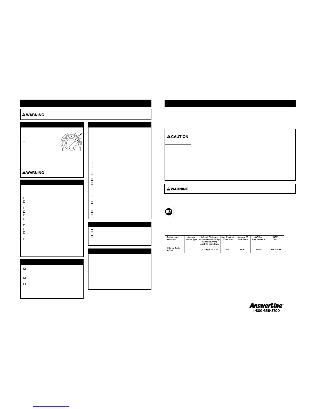
Tested and Certified by NSF International against
NSF/ANSI Standard 42 in model F-201 for the reduction
of claims specified on the Performance Data Sheet.
Electric Shock Hazard: To prevent electrical shock, disconnect power before
servicing unit. Use only a properly grounded and polarized electric outlet.
CARE AND USE
Scalding Hazard: Do not allow
water to boil. May result in
severe burns.
Factory temperature pre-set is 200˚F.
To reset the thermostat to 200°,
turn the indicator two notches to
the right of vertical.
Adjust the thermostat
slowly, turning the dial
clockwise to increase
temperature or counter
clockwise to decrease temperature, then
activate faucet handle for 20 se conds to
bring in fresh water to be heated at the new
setting. Allow 5-7 minutes for wate r to reach
new temperature.
ADJUSTING THE THERMOSTAT
Only use mild cleaners to clean the faucet
and plastic components.
Cleaners with acids, abrasives, alkaline or
organic solvents will result in deterioration of
the plastic components and void the warranty.
CLEANING THE FAUCET AND TANK
Replace filter cartridge when there is an obvious decrease
in water flow to the faucet or if there is an objectionable
taste or odor to the water.
When the inlet and outlet ports have been closed and
the filter’s internal pressure has been relieved, water
(about 2 oz) will discharge from vent line.
If the new filter cartridge cannot be inserted, insert the
old one and turn until it stops, remove it and then retry
the new cartridge.
Carbon filters should be replaced within 12 months.
FILTER GUIDE AND REPLACEMENT
Filter replacement instructions:
Replace with an InSinkErator® filter.
Place pan or dish towel under the filter to
catch water drainage during change.
Slowly turn the cartridge counter-clockwise
completely until it stops (1/4 turn).
Pull cartridge straight down and discard.
Insert new cartridge into filter head.
Top surface of cartridge will become flush
with the bottom of the filter head when
fully engaged.
Turn the cartridge clockwise until it stops
(1/4 turn).
Align the in/out arrow on the head and
bracket assembly to the in/out arrow on
the cartridge.
Open faucet to expel trapped air.
Run water for 3 minutes before usage.
Regularly inspect the unit for any signs of
leakage. If there are signs of water damage,
immediately remove the unit from service.
To avoid water damage from leakage,
replace all cut, loose or split tubing.
A drain pan, plumbed to an appropriate
drain or outfitted with a leak detector,
should be used in those applications where
any leakage could cause
property damage.
PROPERTY DAMAGE
Anytime the instant hot water dispenser is not used for
extended periods of time, unplug and drain unit. If it is below
freezing you will need to unplug the unit and drain it.
Disconnect power from unit (unplug unit).
Push hot water dispenser faucet lever and
allow water to flow until it is cool.
Shut the cold water supply off at the valve.
Disconnect tubes from the tank.
Unhook tank from wall.
Hold tank upside down and drain the water
into the sink.
Towel dry any water drippings from tank area.
Reinstall tank to wall and reconnect tubes.
Remove and discard filter cartridge,
if applicable.
To put back into working order, install new
filter cartridge (if applicable) and turn on cold
water supply at valve. Depress the hot water
dispenser faucet lever and hold until water
flows from the spout. Reconnect the
electrical cord. (Refer to Page 11, Step 6B)
SEASONAL STORAGE/DRAINAGE
approx. 200°
Regularly check for signs of corrosion
by examining the appearance of the
dispensed water.
If there is any discoloration or rusty appearance,
unplug and drain unit as described in the
Seasonal Storage/Drainage section on this
page of the manual.
If the water discoloration remains after
draining and refilling unit, discontinue use
and contact an authorized InSinkErator
service agent.
PERSONAL INJURY
14 15
Page 9

Dispensador de agua caliente instantánea
Manual del usuario
CONTEMPORARY
ANTIQUE
TUSCAN
MODERN
Instalación, cuidado y uso
Installation, Care & Use
Installation, soin et utilisation
SST-FLTR
GN/HC1100
GN/HC2200
GN/HC2215
H/HC3300
WHAT TO DO
Water and steam spits
forcefully from spout
without turning on the
dispenser faucet.
Water is not hot.
• Unit is boiling.
May be normal during initial setup.
• The unit is unplugged.
• The electric outlet is inoperative.
• Activate faucet lever to release some water from
the tank.
• Adjust water temperature using dial on tank front.
Remember that at higher altitudes, water boils
at lower temperatures.
• Make sure the unit is connected to a properly grounded
electric outlet.
• Make sure the circuit breaker or fuses are
functioning properly.
• Check that the outlet is not switched off.
Water is too hot
or not hot enough.
• Thermostat is not adjusted to
your needs.
•
Adjust the thermostat slowly, then activate faucet lever for 20
seconds to bring in fresh water to be heated at the new setting.
Allow 5-7 minutes for water to reach new temperature.
Water comes out the
vent instead of spout.
• Outlet tube is blocked. • Check that outlet tube is not kinked, twisted or pinched.
• Unscrew spout end piece and clean out any debris.
Water is dripping from
the spout/vent
intermittently.
• The expansion chamber isn’t draining
properly due to low water pressure.
• The spout is blocked.
• Unplug the unit. If the dripping doesn’t stop after a few
minutes, check the supply valve to ensure that is fully
open and there are no obstructions in the water line
reducing the pressure below 30 psi (i.e., a poorly mounted
saddle valve, a clogged water filter, or a partially opened
shut-off valve).
• Unscrew spout end piece and clean out any debris.
Water is dripping
from the spout/vent constantly.
• Debris in the water line may be
in the faucet valve seat causing a
slow water leak.
• Unscrew spout end piece and clean out any debris.
• Activate faucet lever 7-10 times to flush faucet & lines.
Divided stream.
• Debris in the end piece. • Unscrew spout end piece and clean out any debris.
PROBLEM POSSIBLE CAUSE
FILTRATION ISSUES
If you are still experiencing trouble call the AnswerLine® 1-800-558-5700.
Water taste or odor. • Filter needs to be flushed out.
• Life of filter has expired.
• Activate the faucet lever and run until the water is cold.
If there is no change, replace filter cartridge.
Please read Troubleshooting Guide and/or visit
www.insinkerator.com before calling AnswerLine
®
Water discoloration/rusty
appearance.
• Corrosion of unit. • Unplug and drain unit as described in the Seasonal
Storage/Drainage Section on page 14 of this manual. If the
water discoloration remains after draining and refilling unit,
discontinue use and contact an authorized InSinkErator
service agent.
New filter leaks or
doesn’t fit.
No water flow or
low water flow.
• Head and bracket not fully rotated.
• Filter O-ring breach.
• Life of filter has expired.
• Remove, inspect, reinstall filter cartridge.
• Remove new filter, replace with old filter. Check operation.
If OK, reinstall new filter and recheck operation.
• Replace filter cartridge. See page 14.
TROUBLESHOOTING
16
Page 10

CÓMO USAR ESTE MANUAL DE INSTRUCCIONES
Describe paso a paso en forma narrativa el proceso de instalación, con cuadros que usted
puede ir marcando conforme avanza en la instalación.
Contiene ilustraciones sencillas como ayuda visual para la narración.
Enunciados de PRECAUCIÓN, ADVERTENCIA y PELIGRO que requieren su atención
durante el proceso.
Estas instrucciones están divididas en apartados principales indicados por números, y apartados
secundarios indicados por letras mayúsculas. El manual está organizado en esta forma para
permitir al usuario hacer una pausa en cualquier momento después de terminar un apartado
principal o secundario sin afectar el proceso de instalación.
Lo que usted verá en el
manual de instrucciones:
1
2
3
VISTA GENERAL DE LA
INSTALACIÓN TERMINADA
A
INSTALACIÓN DEL GRIFO
Desempaque los componentes
del dispensador.
Enderece con cuidado el tubo de cobre
sobre una superficie firme y plana.
Daños materiales: No apriete ni rompa el tubo de
cobre. No deforme la última pulgada (2.5 cm) del
extremo del tubo de cobre.
ÓPRECAUCI N
1
2
Una situación potencialmente peligrosa que si no se evita podría causar la muerte o lesiones graves.
Una situación potencialmente peligrosa que si no se evita podría causar lesiones menores o moderadas.
3
PRECAUCIÓN
ADVERTENCIA
Identifique el número de modelo de su dispensador y anótelo aquí:________________
F-HC3300/F-H3300F-HC1100 F-GN1100
F-GN2215F-HC2215
F-GN2200
F-HC2200
Equipo que puede necesitar:
Nos complace que haya elegido el dispensador de agua caliente instantánea InSinkErator® para
formar parte de su hogar. Con este singular electrodoméstico usted ahorrará tiempo y esfuerzo
en su cocina, y disfrutará al descubrir un nuevo uso cada día. Es por eso que millones de
personas utilizan hoy en día el dispensador de agua caliente instantánea InSinkErator.
Confiamos en que al aplicar las instrucciones paso por paso, usted estará disfrutando pronto de
los beneficios del agua caliente instantánea.
Para su satisfacción y propia seguridad, lea todas las instrucciones, así como los enunciados de precaución y
advertencia antes de instalar o de utilizar su dispensador de agua instantánea.
Esta unidad en particular no está preparada para uso comercial.
Verifique que todo el cableado y conexiones eléctricas cumplan con las especificaciones de las normas de su localidad.
El dispensador debe enchufarse en una toma eléctrica estándar de 115 voltios con conexión a tierra ubicada bajo
el fregadero.
Esta toma eléctrica debe tener energía ininterrumpida.
La toma debe contar con un fusible y no debe ser controlada por el mismo interruptor de pared con el que
funciona el dispensador, excepto si usted tiene un interruptor marca SinkTop Switch
de InSinkErator®.
Se recomienda la instalación de una válvula de corte en la línea de agua fría que alimenta de agua al sistema.
Si usted sospecha niveles elevados de cloro en el agua, o si el agua tiene una apariencia ferrosa antes de instalar
esta unidad, se recomienda utilizar nuestro sistema de filtración de agua.
Este producto contiene acero inoxidable. El fabricante no puede garantizar contra el agua ferrosa debido a la
cantidad de factores que están involucrados más allá del control del fabricante. No obstante, la apariencia
repentina de agua ferrosa descargada del distribuidor de agua caliente puede indicar la necesidad de servicio
o reemplazo de este producto.
El uso de un filtro de agua NO DEBE causar disminución de la presión por abajo de 30 psi (207 kPa). En caso de
ocurrir, esto impedirá el funcionamiento correcto de la unidad.
Las partes internas del tanque provocan un traqueteo normal.
LO QUE USTED DEBE SABER ANTES DE COMENZAR
Herramientas:
QTaladro
QConector “T”
QVálvula de control dedicada
QLlave ajustable
QDestornilladores phillips y planos
QLápiz
QCinta métrica
Tarugos para panel de yeso
Broca corta-círculos
Llave para fregadero
Punzón
Si tiene planeado usar el orificio del rociador del fregadero para el dispensador, es posible que
necesite una llave para fregadero y un tapón de 1/8” o 1/4” (no incluido) para la manguera del
rociador. Vea el paso 1-B.
Si necesita hacer un orificio para montaje en un fregadero de acero inoxidable, es posible que
necesite una broca corta-círculos de 1 1⁄4” a 1 1⁄2” para cortar el acero inoxidable o un punzón. Si
va a perforar una superficie que no sea de acero inoxidable, solicite los servicios de un profesional.
LO QUE USTED NECESITA PARA COMENZAR
18 19
Page 11

B
Cierre la toma del agua.
En la parte superior del tanque, oprima el
anillo de liberación o la pestaña de
liberación gris en el accesorio de
conexión rápida que asegura el tubo azul
o de cobre 1/4" y tire suavemente de la
línea para retirarla del accesorio. Saque el
tubo blanco de 7/16" y el transparente
de 5/16" de sus conectores.
Si aún no está equipado, deberá
instalarse el accesorio de conexión a
presión incluido.
Para instalar el accesorio de conexión a
presión, destornille la tuerca de montaje
de bronce y retire el accesorio de
conexión a presión, el casquillo de
bronce y la tuerca.
A
Deslice la tuerca de latón y el casquillo
de plástico en el tubo de 1/4" de cobre
o azul que viene desde el grifo.
Inserte el tubo azul o de cobre en el
conector de inserción y apriete la tuerca
de latón con una llave entre 1 y 2 vuelta
en sentido horario.
Si lo desea, puede utilizar el soporte de
montaje usado con el tanque.
Pase a la página 25, pasos 3 y 4, para
obtener instrucciones de instalación completas.
A
Cierre la toma del agua.
Retire los tubos del tanque: en la parte
superior del tanque, oprima la pestaña de
liberación de color gris en el accesori de
conexión rápida que asegura el tubo azul
o de cobre de 1/4" y tire suavemente de
la línea para sacarla del accesorio. Saque
el tubo blanco de 7/16" y el transparente
de 5/16" de sus conectores.
Retire el grifo anterior y continúe con la
página 22.
Tubo azul
Daños materiales: no apriete
excesivamente la tuerca de latón.
Daños materiales: no apriete ni rompa
el tubo de cobre. No deforme la última
pulgada (2.5 cm) del extremo de cobre.
PRECAUCIÓN
Daños materiales: desconecte el tanque
antes de desconectar la tubería.
PRECAUCIÓN
PRECAUCIÓN
Pestaña
de liberación
1/4"
azul
7/16"
blanco
5/16"
trans-
parente
Compruebe
la orientación
del casquillo
Tome nota de
la orientación
del casquillo
PARA INSTALAR SÓLO UN GRIFO NUEVO
PARA INSTALAR SÓLO UN TANQUE NUEVO
Si va a instalar un grifo nuevo Y un tanque nuevo, pase a la página 22.
SST-FLTR
Cabeza
del Filtro
Tubo de 3/8" ( 2)
Tubo de la
Descarga del Filtro de 6"
Cartucho
de Filtro
Tuerca de latón/Casquillo/
Inserto para tubo
F-HC1100 F-GN1100
F-HC2215 F-GN2215
F-HC2200 F-GN2200
Placa de montaje
semicircular
Anillo "O" de caucho
Tuerca
hexagonal
Asiento de bronce
(HC3300, H3300)
Herramienta
hexagonal
Adaptador de encaje
a presión (3 piezas)
Tornillos de 3/4" (4)
Conector rápido
con forma de Y
F-H3300
F-HC3300
Tapón (1)
CONTENIDO DE ESTE PAQUETE
20 21
Page 12

Daños materiales: no apriete ni rompa el tubo de
cobre. No deforme la última pulgada (2.5 cm) del
extremo del tubo de cobre.
Coloque la placa de montaje semicircular en
el perno roscado por abajo del fregadero.
Enrosque la tuerca hexagonal en el
perno. Compruebe que la cabeza del
grifo quede al ángulo deseado.
Inserte un destornillador en el orificio de
la herramienta hexagonal (para formar
una “T”), y apriete la tuerca y fije el grifo
con esta herramienta.
2
La placa de montaje semicircular debe circundar
todos los tubos que descienden y rebasar el
agujero del fregadero cuando esté apretada.
Compruebe que la junta tórica quede
sentada correctamente en la base de
la cabeza del dispensador (la ranura
en la parte inferior del dispensador).
Inserte los tubos por el orificio en
el fregadero o cubierta hasta que el
extremo descanse en la superficie del
fregadero o cubierta.
Desempaque los componentes
del dispensador.
Enderece con cuidado el tubo de
cobre sobre una superficie firme
y plana.
Para facilitar el paso de los tubos a través
del orificio, inserte primero el tubo azul con
el accesorio de conexión rápida y luego
coloque los tubos restantes.
B
A
C
D
PRECAUCIÓN
Asegúrese de usar una junta tórica de
caucho para obtener un sellado correcto.
INSTALACIÓN DEL GRIFO - 1100/2200
PREPARACIÓN
COMIENCE AQUÍ
LA INSTALACIÓN CORRECTA DEBE HACERSE ENTRE 2-4 HORAS
Identifique las ubicaciones del
grifo, tanque y filtro (si es el caso)
del dispensador.
Compruebe que haya espacio libre
suficiente (vea la tabla a la izquierda) para
poder abrir las manijas del dispensador.
Asegúrese de que la cubierta no sea de-
masiado gruesa (máximo de 3
").
Asegúrese de que haya una toma eléctrica
con conexión a tierra debajo del fregadero.
1
A
El tomacorriente de pared para su surtidor debe estar constantemente
energizado y protegido con fusibles. No debe estar controlado por el
mismo interruptor de pared que opera su triturador de desechos, a
menos que use un interruptor InSinkErator SinkTop Switch
TM
.
Cierre la toma del agua.
Si utiliza el orificio de la manguera del
rociador, quite la tuerca que conecta la
manguera del rociador debajo del grifo.
Quite con la llave ajustable la pestaña
de la arandela del rociador que está en
el orificio del rociador.
Tape la abertura de la manguera con un
tapón de 1/8" o de 1/4" (
no incluido).
B
Si es necesario perforar el fregadero o la
cubierta, es posible que tenga que rentar o
comprar las herramientas apropiadas.
Consulte los servicios de un profesional
antes de perforar una superficie que no
sea de acero inoxidable.
C
Si no hay un orificio para rociador
o si no lo usa
Muchas personas colocan un
dispensador de agua caliente
instantánea en lugar de un dispensador
para jabón en el fregadero
.
Si perfora un fregadero de acero
inoxidable o una cubierta, puede hacer
el orificio de montaje para el dispensador
con una broca corta-círculos en el acero,
o puede usar un punzón.
Tamaño requerido del agujero
F-HC1100 ................25⁄8" (7 cm)
F-GN1100 ................3
1
⁄4" (8 cm)
F-HC2200 ................2
7
⁄8" (7 cm)
F-GN2200 ................3
1
⁄2" (9 cm)
F-HC2215 ................2
7
⁄8" (7 cm)
F-GN2215 ................3
1
⁄2" (9 cm)
F-HC3300 ................2
1
⁄2" (6 cm)
F-H3300 ...................2
1
⁄2" (6 cm)
Mínimo requerido del centro
del orificio a la pared
El grosor máximo de la cubierta
(profundidad) es de 3 pulgadas (5 cm)
F-HC1100 .................. 1
3
⁄8" - 11⁄2" (3.5 - 3.8 cm)
F-GN1100 .................. 1
1
⁄4" - 11⁄2" (3.1 - 3.8 cm)
F-HC2200 .................. 1
3
⁄8" - 11⁄2" (3.5 - 3.8 cm)
F-GN2200 .................. 1
1
⁄4" - 11⁄2" (3.1 - 3.8 cm)
F-HC2215 .................. 1
3
⁄8" - 11⁄2" (3.5 - 3.8 cm)
F-GN2215 .................. 1
1
⁄4" - 11⁄2" (3.1 - 3.8 cm)
F-HC3300 .................. 1
3
⁄8" - 11⁄2" (3.5 - 3.8 cm)
F-H3300 .................... 1
3
⁄8" - 11⁄2" (3.5 - 3.8 cm)
22 23
Puede ser necesario un ayundante paravel
dispensador mientras se fija en su lugar.
Page 13

Monte el tanque verticalmente en un lugar
que permita tener un espacio libre abajo para
drenarlo si es necesario.
NO APRIETE los tornillos excesivamente.
Haga orificios guía de 1/8" (0.3 cm) en
las marcas.
Inserte los tornillos en los orificios guía y
deje 1/4" (0.6 cm) de tornillo expuesto.
Cuelgue el tanque en los tornillos.
Apriete los tornillos media vuelta.
B
A
Seleccione un punto debajo del fregadero
para montar el tanque verticalmente al
alcance de las conexiones de plomería
y eléctricas. El tanque debe estar a una
distancia máxima de 16" (40 cm) del
grifo y a una distancia máxima de 30"
(75 cm) de una toma eléctrica estándar
con conexión a tierra.
Sostenga el tanque en el punto
seleccionado para instalarlo y marque
con un lápiz los lugares para colocar
dos tornillos para colgarlo.
Daños materiales: el tanque debe estar
colocado dentro de una distancia de 16" (40 cm)
del grifo y a 30" (75 cm) o menos de una toma
eléctrica estándar con conexión a tierra. NO
EXTIENDA las líneas de plomería y eléctricas.
3
Inserte el conector de inserción del tubo
azul o cobre de 1/4" en el conector
rápido (izquierda) del tanque. (1)
Inserte el tubo blanco flexible de 7/16"
en el conector escalonado del centro
y deslícelo aproximadamente 1/2"
(1.3 cm). (2)
Inserte el tubo transparente de 5/16" en
el conector liso de la derecha y deslícelo
aproximadamente 1/2" (1.3 cm). (3)
Revise visualmente para que los tubos
no queden aplastados ni torcidos.
A
Daños materiales: las líneas de agua estrechas
o bloqueadas pueden dañar al tanque. Asegúrese
de que los tubos estén conectados correctamente
y se hayan metido tanto como sea posible.
Los tornillos incluidos sólo deben usarse en
montantes de madera o gabinetes. Para instalarse
en paneles de yeso utilice tarugos (no incluidos).
Deje los tornillos
expuestos 1/4" (0.6 cm)
para colgar el tanque.
ADVERTENCIA
PRECAUCIÓN
El tanque debe
montarse nivelado
para asegurar su
funcionamiento
correcto.
Las abrazaderas de manguera no son necesarias
para cualquiera de las conexiones.
4
(1) (2) (3)
MONTAJE DEL TANQUE
CONEXIÓN DEL GRIFO EN EL TANQUE
Daños materiales: no apriete ni rompa
el tubo. No deforme la última pulgada
(2.5 cm) del extremo del tubo de cobre.
Coloque la placa de montaje
semicircular en el perno roscado
por abajo del fregadero.
Coloque la tuerca hexagonal en el
perno roscado. Asegúrese de que el
mango del distribuidor esté del lado
correcto y la cabeza del grifo esté en
el ángulo deseado.
Inserte un destornillador en el orificio
de la herramienta hexagonal (para
formar una “T”), y apriete la tuerca y
fije el grifo con esta herramienta.
2
La placa de montaje semicircular debe circundar
todos los tubos que descienden y rebasar el
agujero del fregadero cuando esté apretada.
Inserte la junta tórica de goma en
la ranura del asiento de bronce.
Coloque el asiento de bronce, con
la junta tórica hacia abajo, sobre el
orificio del fregadero o la encimera.
Sujete el asiento de bronce en su
lugar, coloque los tubos a través del
orificio del fregadero o la encimera
hasta que la base haga contacto con
el asiento de bronce.
Gire el asiento de bronce hasta que
ambos pernos de retención calcen
en los orificios de la base del grifo y
la base se asiente firmemente en el
asiento de bronce.
Desempaque los componentes
del dispensador.
La instalación recomendada para este
grifo es con el mango del distribuidor
hacia la derecha.
El diseño exclusivo permite que el
mango sea completamente funcional
cuando se lo instala a la derecha o a
la izquierda del grifo. Determine la
ubicación preferida del mango antes
de la instalación.
Para facilitar el paso de los tubos a través
del orificio, inserte primero el tubo azul con
el accesorio de conexión rápida y luego
coloque los tubos restantes.
B
A
C
D
PRECAUCIÓN
Humedecer la junta tórica antes de colocarla
en el asiento de bronce ayuda a que la junta
permanezca en su lugar durante la instalación.
INSTALACIÓN DEL GRIFO - 3300
24 25
Page 14

Tuerca de latón
Casquillo
Inserto de latón
Tubo de
plástico
de 3/8”
Riesgo de quemadura: la llave entrega agua casi en
ebullición (212 ˚F) la cual puede producir quemaduras
instantáneas. Tenga cuidado cuando opere este equipo.
ADVERTENCIA
Daños materiales: conecte el tubo restante
al agua fría de entrada solamente.
PRECAUCIÓN
C
Abra la línea de agua.
Oprima la manija HOT (CALIENTE) del
dispensador hasta que salga el agua por el
grifo (aproximadamente 1 a 2 minutos).
Deje salir el agua por lo menos durante dos
minutos para limpiar las líneas (las manijas de
agua caliente y fría en forma independiente si
es el caso).
Nota: consulte el cuadro a continuación para
obtener instrucciones especiales sobre el
funcionamiento de los grifos modernos InDulge
™
.
B
A
Revise todas las conexiones para asegurarse de
que estén apretadas
y que no presenten fugas.
Enchufe el tanque de agua caliente.
El agua saldrá fría en un principio.
Espere entre 12 y 15 minutos para que el agua se
caliente a la temperatura indicada.
Durante el ciclo inicial de calentamiento es normal
escuchar gorgoteos y siseos.
6
Instale una “T” (no incluido) en la línea
de agua fria.
Instale la válvula de control de agua dedicada con
el accesorio de compresión de 3/8".
En el extremo del tubo blanco de 3/8" que sale
del conector rápido, deslice la tuerca de latón y el
casquillo y luego coloque el inserto para tubo.
Inserte el tubo blanco de 3/8" en la conexión de
compresión de 3/8" y apriete.
Daños materiales: es necesario tener una toma
eléctrica estándar con conexión a tierra a una
distancia de 30” (75 cm) debajo del fregadero. No
utilice extensiones eléctricas con el dispensador.
ADVERTENCIA
Si el agua que viene del grifo no es caliente 15 minutos después de que se ha enchufado la
unidad (o para otras ediciones relacionadas con la operación de su dispensador inmediato
de la agua caliente) consulte a la sección de “localización de averías” en la página 32.
CONEXIÓN FINAL DEL AGUA
Con el sistema OptiPush™ de activación de agua
caliente con cierre automático y sistema de
activación de agua fría Stay-On
™
, que mantiene el
grifo abierto cuando se utiliza agua fría.
HC3300: para utilizar agua caliente instantánea,
primero presione hacia abajo la manija del grifo y
luego oprima la manija hacia atrás en el sentido
del indicador rojo que se encuentra en la parte
superior de la manija. Para utilizar agua fría, primero
presione la manija del grifo hacia abajo y luego
empuje la manija hacia adelante en el sentido
del indicador azul que se encuentra en la manija.
Con el sistema Optipush
™
de activación de agua
caliente con cierre automático.
H3300: para utilizar agua caliente instantánea,
primero presione hacia abajo la manija del grifo y
luego empuje la manija hacia atrás en el sentido
del indicador rojo que se encuentra en la parte
superior de la manija.
Instrucciones de operación para los grifos modernos InDulge
TM
Distribución de agua
caliente (HC3300, H3300)
Distribución de
agua fría (HC3300)
Riesgo de quemadura: la llave entrega agua casi en ebullición (212 ˚F) la cual puede producir quemaduras instan-
táneas. Tenga cuidado cuando opere este equipo.
ADVERTENCIA
PRECAUCIÓN
Lesiones personales: no coloque el filtro por
encima de una toma eléctrica o de otro aparato.
Instale la cabeza y el soporte de tal forma que no
sea necesario estirar, torcer o estrechar la tubería.
Daños materiales: los tramos de tubo necesitan tener
el mismo contorno del gabinete para dejar espacio de
almacenamiento sin curvas pronunciadas. Los cortes
de los tubos deben ser limpios, perpendiculares y no
tener rebabas para garantizar una conexión correcta.
Determine la longitud requerida del
tubo y corte el tubo en forma
perpendicular y sin dejar rebabas.
Inserte un tubo blanco de 3/8" en el lado
de entrada de la cabeza del filtro hasta
que tope. Oprima una vez más para
asegurar una conexión correcta.
Inserte el otro tubo blanco de 3/8" en
el lado de salida de la cabeza del filtro
hasta que tope. Oprima una vez más
para asegurar una conexión correcta.
Marque la ubicación de los orificios para
la cabeza y el soporte en un lugar que
permita cambiar el filtro.
Haga orificios guía de 1/8" (0.3 cm), fije el
soporte en la pared con tornillos de madera
y gire éstos hasta que queden apretados.
Quite el tapón rojo del filtro, inserte el
cartucho en la cabeza del filtro y gírelo
en sentido horario hasta que la flecha
“LOCK” del filtro quede alineada con la
flecha del soporte.
desde la línea de
suministro de agua
hacia
el dispensador
ADVERTENCIA
PRECAUCIÓN
Daños materiales: no estire las líneas a más de las
16” (40 cm) proporcionadas. Verifique que el (los) tubo(s)
y el conector en “Y” estén bien ajustados.
La descarga de agua de aproximadamente 2 oz.
(60 ml) es normal, cuando el filtro es retirado.
Para redireccionar la descarga de agua al
reemplazar el filtro, coloque el tubo claro
de 6" (152 mm) sobre el respiradero en el
lado izquierdo de la cabeza del filtro.
Nota: se requiere el accesorio de 3/8"
para realizar la conexión del suministro
de agua.
Conecte el tubo restante blanco de
3/8" a la línea de suministro de agua de
entrada. (Vea el paso 6)
C
Inserte el (los) tubo(s) de cobre del
dispensador en el conector rápido en
“Y” y utilice el tapón para los modelos
que solo suministran agua caliente.
Conecte el tubo blanco de 3/8" de la
salida del lado derecho en la cabeza del
filtro en el conector rápido hasta que
tope. Oprima una vez más para
asegurar una conexión correcta.
Para quitar el tubo de cada conector rápido, oprima
el anillo de liberación y saque el tubo con cuidado.
D
Tubo de descarga
desde la línea
de suministro
de agua
5
hacia
el dispensador
INSTALACIÓN DEL FILTRO
Los tornillos incluidos sólo deben usarse en
montantes de madera o gabinetes. Para instalarse
en paneles de yeso utilice tarugos (no incluidos).
26 27
desde el filtro o linea
de entrada del agua
Plug
desde el filtro o linea
de entrada del agua
HC1100, HC2200,
HC2215
GN1100, GN2200, GN2215,
HC3300, H3300
A
B
Page 15

Riesgo de incendio: para minimizar la posibilidad de incendio, NO GUARDE objetos
infla mables como trapos, papel o envases con aerosol cerca del tanque. NO GUARDE o
use gasolina u otros vapores o líquidos inflamables cerca de éste u otros aparatos eléctricos.
Riesgo de descarga eléctrica: el uso del dispositivo sin conexión a tierra o conectado
incorrectamente puede ocasionar lesiones graves o la muerte debido a una descarga eléctrica.
Lesiones personales: este tanque no trabaja a presión. NO MODIFIQUE este sistema.
NO CIERRE el tubo de purga ni conecte otro tipo de dispensadores o válvulas en
el tanque. Utilice sólo el grifo del dispensador InSinkErator proporcionado. Utilice
sólo las partes incluidas en el paquete. Si necesita reparación o partes de repuesto,
comuníquese con su agente autorizado de servicio InSinkErator.
ADVERTENCIA
ADVERTENCIA
PRECAUCIÓN
PRECAUCIÓN
Daños materiales: para evitar daños causados por el agua, cambie cualquier tubería
floja o dañada. Inspeccione periódicamente la unidad para detectar posibles signos
de fugas y retírela de servicio inmediatamente si sospecha que presenta fugas.
Este electrodoméstico debe estar conectado a tierra. Este dispensador está equipado con un cable eléctrico que
tiene un conductor con conexión a tierra y un polo de conexión a tierra. El enchufe debe conectarse a una toma
instalada correctamente y conectada a tierra de acuerdo con los códigos y normas eléctricas de su localidad. No
modifique el cable proporcionado con el aparato; en caso de que no se pueda enchufar en la toma, contrate los
servicios de un técnico especializado para instalar la toma eléctrica. Si duda de que su dispensador esté conectado
correctamente a tierra, consulte a un técnico especializado.
Un distribuidor instantáneo de agua caliente, como cualquier calefactor de agua, tiene una vida limitada
y fallará eventualmente. Para evitar posibles daños a la propiedad y lesiones personales, este distribuidor
instantáneo de agua caliente debe examinarse regularmente para ver si tiene fugas y/o corrosión y debe
reemplazarse cuando sea necesario. Se debe utilizar una bandeja de drenaje, conectada a un drenaje
adecuado o equipada con un detector de fugas, en aquellas aplicaciones donde las fugas pudieran
ocasionar daños a la propiedad. Para verificar si existe corrosión, examine la apariencia del agua distribuida
en un vaso transparente una vez cada tres (3) meses. Si existe decoloración o una apariencia ferrosa,
desconecte y drene la unidad tal como se describe en la sección Almacenamiento/Drenado de temporada
en la página 30 de este manual. Si la decoloración del agua permanece después de drenar y rellenar la
unidad, descontinúe el uso y póngase en contacto con un agente de servicio autorizado por InSinkErator.
Esta es una garantía que InSinkErator®, una división de Emerson Electric Co., (“InSinkErator”, “Fabricante”, “nosotros”, “nos” o
“nuestro”) brinda al cliente original propietario del producto InSinkErator (el “Producto InSinkErator”) y a cualquier otro propietario
posterior de la residencia en la que se instaló originalmente el Producto (“Cliente”, “usted” o “su”).
InSinkErator le garantiza al Cliente que su Producto InSinkErator no tendrá defectos en el material o la mano de obra, sujetos a las
exclusiones descritas a continuación, durante el “Período de garantía”, que comienza luego de: (a) la fecha en la que se instaló
originalmente su Producto InSinkErator, (b) la fecha de compra o (c) la fecha de fabricación indicada por el número de serie de
su Producto InSinkErator. Deberá presentar la documentación escrita correspondiente para justificar (a) o (b). En caso de que no
pueda presentar la documentación para justificar (a) o (b), la fecha de inicio del Período de Garantía quedará a consideración del
Fabricante, bajo su único y absoluto criterio, basado en el número de serie del Producto InSinkErator.
Qué cubre la garantía
Esta garantía cubre los defectos en el material o la mano de obra, sujetos a las exclusiones descritas a continuación, en lo que respecta
a los Productos InSinkErator a los que el Cliente confiera un uso doméstico únicamente, e incluye todas las piezas de repuesto y los
gastos de reparación. SU ÚNICO Y EXCLUSIVO RECURSO SEGÚN LOS TÉRMINOS DE ESTA GARANTÍA LIMITADA SERÁ LA
REPARACIÓN O EL REEMPLAZO DEL PRODUCTO INSINKERATOR.
Qué no cubre la garantía
Esta garantía limitada no se extiende y excluye expresamente lo siguiente:
• Pérdidas, daños o incapacidad de operar el Producto InSinkErator, como resultado de circunstancias fuera del control del
Fabricante, sin limitaciones, tales como: accidente, alteración, mal uso, abuso, abandono, negligencia (de otra persona que
no sea el Fabricante), instalación, mantenimiento, ensamblaje o montaje inadecuados del Producto InSinkErator que no
respeten las instrucciones del Fabricante o los códigos eléctricos y/o de plomería locales.
• Desgaste como resultado del uso normal del producto, lo que incluye sin limitaciones, oxidación de la superficie, rayones,
abolladuras o pérdidas o daños similares y razonables.
Además de las exclusiones antes descritas, esta garantía no se aplica en caso de que los Productos InSinkErator se instalen para
fines industriales o comerciales.
No se aplica ninguna otra garantía expresa
Esta es la única y exclusiva garantía que se le brinda al Cliente descrito anteriormente. No se aplica ninguna otra garantía expresa,
oral o escrita. No se autoriza a ningún empleado, agente, distribuidor u otra persona a alterar esta garantía limitada o a brindar
cualquier otra garantía en nombre del Fabricante. Ninguna persona podrá modificar los términos de esta garantía,
independientemente de si se trata del Fabricante, el propietario original o sus respectivos sucesores o beneficiarios.
Qué haremos para solucionar los problemas
Si su Producto InSinkErator no funciona de acuerdo con la documentación que usted recibió, o si tiene dudas acerca de su
Producto InSinkErator o no sabe cómo determinar cuándo necesita servicio técnico, comuníquese con la línea de ayuda gratuita
InSinkErator AnswerLine al 1 (800) 558-5700 o bien, visite nuestra página web en www.insinkerator.com. También puede escribirnos
a: Centro de Servicio InSinkErator, 4700 21st Street, Racine, Wisconsin, 53406, EE. UU.
En el reclamo de garantía debe especificar la siguiente información: su nombre, dirección, número de teléfono, modelo y número de
serie de su Producto InSinkErator y, si es necesario o si se lo solicitan, una confirmación por escrito de: (a) la fecha que figura en su
recibo de instalación, o (b) la fecha que figura en su recibo de compra.
El Fabricante o el representante de servicio autorizado determinarán, bajo su único y absoluto criterio, si esta garantía cubre su
Producto InSinkErator. Se le proporcionará la información de contacto del Centro de Servicio Autorizado de InSinkErator más
cercano. Comuníquese directamente con dicho centro para recibir servicios de reparación o reemplazo cubiertos por la garantía en
su hogar. El representante de servicio autorizado de InSinkErator es el único capaz de brindarle el servicio de garantía. InSinkErator
no se hace responsable por los reclamos de garantía que surjan como consecuencia de trabajos realizados en su Producto
InSinkErator por cualquier otra persona que no sea el representante de servicio autorizado de InSinkErator.
Si un reclamo cubierto se realiza durante el Período de Garantía, el Fabricante reparará o reemplazará su Producto InSinkErator
por intermedio de su representante de servicio autorizado. Usted no deberá afrontar el costo de las piezas de repuesto o de un
nuevo Producto InSinkErator, ni el costo de mano de obra para la reparación o instalación del Producto InSinkErator de reemplazo.
El Fabricante o su representante de servicio autorizado, bajo su exclusivo criterio, determinarán si es necesaria la reparación o el
reemplazo del producto. Recibirá todos los servicios de reparación o reemplazo en su hogar.Si el Fabricante determina que se debe
reemplazar su Producto InSinkErator en vez de repararlo, la garantía del Producto InSinkErator de reemplazo se limitará al plazo
vigente de la garantía original.
Limitación de responsabilidad
EN LA MEDIDA EN QUE LO PERMITA LA LEY, EL FABRICANTE O SUS REPRESENTANTES DE SERVICIO AUTORIZADOS
NO SERÁN RESPONSABLES POR DA—OS INCIDENTALES, ESPECIALES, INDIRECTOS O CONSECUENTES, TALES COMO
DA—OS PATRIMONIALES, YA SEA QUE SEAN CONSECUENCIA DEL INCUMPLIMIENTO, USO, MAL USO O INCAPACIDAD DE
USAR EL PRODUCTO INSINKERATOR, O DE LA NEGLIGENCIA DEL FABRICANTE O SUS REPRESENTANTES DE SERVICIO
AUTORIZADOS. EL FABRICANTE NO SERÁ RESPONSABLE POR LOS DA—OS CAUSADOS POR EL RETRASO EN EL
RENDIMIENTO Y EN NINGÚN CASO, SIN IMPORTAR EL TIPO DE RECLAMO O LAS MEDIDAS IMPLEMENTADAS (AUNQUE SE
BASEN EN EL CONTRATO, UNA CONTRAVENCIÓN, LA NEGLIGENCIA, LA RESPONSABILIDAD ESTRICTA, OTRO AGRAVIO,
ETC.), SU RESPONSABILIDAD EXCEDERÁ EL PRECIO QUE EL PROPIETARIO ORIGINAL HAYA PAGADO POR EL PRODUCTO
INSINKERATOR.
El término “daños consecuentes” debe incluir, entre otros, la pérdida de ganancias anticipadas, la interrupción de los negocios, la
falta de uso o ingresos, el costo del capital, o la pérdida o daño a la propiedad o al equipo.
Algunos estados prohíben la exclusión o limitación de los daños incidentales o consecuentes, de modo que estas limitaciones
pueden no aplicarse en su caso.Esta garantía le otorga derechos legales específicos y también puede tener otros derechos que
varían según el estado.
GARANTÍA LIMITADA TOTAL DE SERVICIO EN SU HOGAR
28 29
Dispensador: 5 años de garantía
Tanques de acero inoxidable: 3 años de garantía
Sistema de Filtración: 1 año de garantía (excluyendo el cartucho del filtro reemplazable)
Page 16

PRECAUCIÓN
ADVERTENCIA
INFORMACIÓN DE LA FILTRACIÓN
El Sistema de Filtración del Surtidor de Agua Caliente al Instante InSinkErator® está diseñado para
usarse en la filtración de sedimentos y del olor y sabor a cloro en el agua potable, y ha sido
evaluado para otros usos. El sistema por lo habitual se instala (cerca o detrás de un fregadero)
donde se desee agua potable filtrada, y se debe instalar, operar y dar mantenimiento tal como se
especifica en las instrucciones de instalación y uso.
Para reducir el riesgo asociado con el daño a la propiedad ocasionado por fugas de agua:
• Proteja el filtro contra la congelación. Drene el filtro cuando la temperatura descienda por
debajo de 40 °F (4.4 °C).
• No instale si la presión de agua excede 120 psi (828 kPa). Si su presión de agua excede
120 psi, debe instalar una válvula limitadora de presión. Póngase en contacto con un
fontanero profesional si no está seguro sobre cómo verificar su presión de agua.
• No instale donde puedan presentarse condiciones de martilleo hidráulico. Si existen
condiciones de martillo de agua o golpe de ariete debe instalar un supresor de
martilleo hidráulico. Póngase en contacto con un fontanero profesional si no está seguro
sobre cómo verificar esta condición.
• No instale sobre líneas de suministro de agua caliente. La temperatura máxima del agua
para la operación de este sistema de filtro es 100 °F (38 °C).
• Se debe reemplazar el cartucho de filtro desechable cada doce meses o en el ciclo de
servicio especificado.
• Lea y siga las instrucciones antes de instalar y usar este sistema.
No lo use con agua que sea microbiológicamente insegura o de calidad desconocida sin
previamente asegurarse de la desinfectación adecuada antes o después de que esa agua
pase por el sistema.
Especificaciones del filtro de reducción química y mecánica F-201R:
(Use el cartucho de sustitución F-201R) Este cartucho (incluido con el sistema) proporciona una reducción
mecánica y química de suciedad y óxido, sabor y olor y cloro.
Capacidad del filtro: 500 galones, dependiendo de las condiciones locales del agua. Tenga en cuenta que las pruebas
se efectuaron en condiciones estándar de laboratorio; el rendimiento real puede variar. No emplee el producto con agua
que no sea segura microbiológicamente o cuya calidad se desconozca sin una desinfección adecuada anterior o posterior
al sistema. Sólo debe utilizarse con agua fría. Los sistemas deben instalarse y utilizarse según los procedimientos y pautas
recomendados por el fabricante. Para la garantía, consulte la tarjeta de garantía. Para reparaciones y piezas, comuníquese
con su distribuidor local o directamente con InSinkErator
®
al 1-800-558-5700.
Pautas de aplicación y parámetros del suministro de agua para las pruebas NSF: Caudal de servicio de 0.75 gpm,
suministro de agua comunitario o de pozo privado, presión del agua entre 20 y 120 psi, temperatura del agua entre 33˚F y
100˚F. Excepto donde se indique lo contrario, todas las pruebas se efectuaron con pH = 7.5 ± 0.5, Caudal: 0.75 gpm,
Presión: 60 psi, Temp: 20˚ ± 3˚C.
En caso de reparaciones o sustitución de componentes, comunìquese con un agent de Servicio autorizado
de InSinkErator.
Probado y certificado por NSF International bajo la norma 42 de
NSF/ANSI en el modelo F-201 para la reducción de los reclamos
especificados en la Hoja de datos de funcionamiento.
Presión: 20-120 psi
Temperatura: 33
º
F - 100ºF
Caudal: 0.75 gpm
Capacidad: 500 gallons
31
Riesgo de descarga eléctrica: para evitar descargas eléctricas, desconecte la electricidad antes
de dar mantenimiento a la unidad. Utilice una toma conectada a tierra y polarizada correctamente.
ADVERTENCIA
ADVERTENCIA
MANTENIMIENTO Y USO
Riesgo de escaldado: no deje hervir el
agua. Esto puede producir lesiones graves.
Use solamente limpiadores suaves para
limpiar el grifo y los componentes de plástico
del dispensador.
El uso de limpiadores que contienen ácidos,
álcalis y disolventes inorgánicos causa
deterioro de los componentes plásticos y
anula la garantía.
LIMPIEZA DEL GRIFO Y DEL TANQUE
La temperatura establecida de fábrica
es de 200 °F. Para reajustar el
termostato a 200°, gire el indicador
dos muescas hacia la derecha de
la vertical.
Ajuste el termostato
lentamente, girando la
carátula en el sentido
de las manecillas el reloj para aumentar la
temperatura o en sentido contrario a las manecillas
del reloj para reducirla, después active el volante
del grifo por 20 segundos para alimentar con
agua fresca que se calentará con este nuevo
ajuste. Espere 5 a 7 minutos para que el agua
alcance la nueva temperatura.
Siempre que el dispensador de agua caliente instantánea no
se utilice por periodos de tiempo prolongados, desenchufe y
drene la unidad. Si la temperatura está por debajo del punto
de congelación, deberá desenchufar la unidad y drenarla.
ALMACENAMIENTO/DRENADO DE TEMPORADA
Desconecte la energía de la unidad (desenchufe
la unidad).
Oprima la palanca del grifo del dispensador de
agua caliente y deje que el agua fluya hasta que
esté fría.
Cierre el suministro de agua fría en la válvula.
Desconecte los tubos del tanque.
Descuelgue el tanque de la pared.
Sostenga el tanque boca abajo y drene el agua
en el fregadero.
Seque con una toalla cualquier resto de agua
que haya quedado en el área del tanque.
Reinstale el tanque en la pared y reconecte los
tubos.
Retire y deseche el cartucho del filtro, si corresponde.
Para poner el dispensador nuevamente en
funcionamiento, instale un cartucho de filtro nuevo
(si corresponde) y abra el suministro de agua fría
en la válvula. Presione la palanca del grifo del
dispensador de agua caliente y sosténgala hasta
que salga agua del surtidor. Reconecte el cable
eléctrico (consulte el paso 6B de la página 27).
aprox. 200°
Reemplace el cartucho del filtro cuando haya una disminución
obvia de la salida del agua por el grifo o cuando el agua tenga
un sabor u olor dudoso.
Cuando los orificios de entrada y salida se han cerrado y se
ha liberado la presión interna del filtro, el agua se descarga
por la línea de purga (aproximadamente 2 oz o 60 ml).
Si no se puede insertar el cartucho nuevo, coloque el
usado y gírelo hasta que se detenga; retírelo y vuelva a
intentar con el cartucho nuevo.
Los filtros de carbón deben cambiarse cada 12 meses.
GUÍA PARA EL FILTRO Y REEMPLAZO
Instrucciones para cambiar el filtro:
Reemplace por un filtro InSinkErator®.
Coloque una charola o un papel toalla para
platos debajo del filtro para contener el agua
drenada durante el cambio.
Gire el cartucho lentamente en sentido contrario
de las manecillas del reloj hasta que se detenga
(1/4 de vuelta).
Jale el cartucho hacia abajo y deséchelo.
Inserte el nuevo cartucho en la cabeza del filtro.
La superficie superior del filtro quedará a ras de
la parte inferior de la cabeza del filtro cuando
ambos estén completamente ensamblados.
Gire el cartucho en sentido horario hasta que
tope (1/4 de vuelta).
Alinee la flecha de entrada y salida in/out) en
el conjunto de cabeza y soporte con la flecha
respectiva del cartucho.
Abra el grifo para expulsar el aire atrapado.
Deje salir el agua durante tres minutos antes de usar.
Revise periódicamente la unidad por posibles
signos de fuga. Si encuentra signos de daños
causados por el agua, retire inmediatamente la
unidad de servicio.
Para evitar que el agua cause daños debido a
fugas, cambie cualquier tubo que encuentre
cortado, suelto o dañado.
En caso de que una fuga pueda causar daños
materiales, se debe usar una bandeja de goteo
conectada a un tubo de drenado adecuado o
equipada con un detector de fugas.
30
DA—OS MATERIALES
AJUSTE DEL TERMOSTATO
Verifique regularmente si existen señales
de corrosión examinando la apariencia del
agua distribuida.
Si existe decoloración o una apariencia ferrosa,
desconecte y drene la unidad tal como se
describe en la sección Almacenamiento/Drenado
de temporada en esta página del manual.
Si la decoloración del agua permanece después
de drenar y rellenar la unidad, descontinúe
el uso y póngase en contacto con un agente de
servicio autorizado por InSinkErator.
LESIONES PERSONALES
Page 17

Distributeur d’eau chaude instantanée
Manuel d'utilisation
CONTEMPORARY
ANTIQUE
TUSCAN
MODERN
Installation, soin et utilisation
Installation, Care & Use
Instalacion, cuidado & uso
SST-FLTR
GN/HC1100
GN/HC2200
GN/HC2215
H/HC3300
IDENTIFICACIÓN Y SOLUCIÓN DE PROBLEMAS
SOLUCIÓN
El agua y el vapor salen
forzadamente por el
grifo sin abrir la manija
del dispensador.
El agua no está caliente.
• El agua de la unidad está hirviendo.
Puede ser durante el ajuste inicial.
• Posiblemente la unidad no
está enchufada.
• La toma eléctrica no funciona.
• Active la palanca del grifo para que salga agua del tanque.
• Ajuste la temperatura del agua con el indicador que está en
frente del tanque.
Recuerde que a mayor altitud, el agua hierve a menor temperatura
• Verifique que la unidad esté enchufada en una toma
eléctrica conectada a tierra correctamente.
• Asegúrese de que el interruptor de circuito o los fusibles
funcionen correctamente.
• Compruebe que la corriente de la toma eléctrica no
esté interrumpida.
El agua está demasiado
caliente o no está suficientemente caliente.
• El termostato no está ajustado como
usted lo necesita.
• Ajuste el termostato lentamente y luego active la manija
del grifo durante 20 segundos para que entre agua
fría y se caliente a la nueva temperatura ajustada.
Espere entre cinco y siete minutos para que el agua se
caliente a la nueva temperatura.
El agua sale por el orificio de purga y no
por la llave.
• El tubo de salida está bloqueado. • Revise que el tubo de salida no esté torcido o estrechado.
• Desatornille la pieza del extremo del grifo y quite cualquier
residuo depositado.
El agua gotea por la llave
u orificio de purga intermitentemente.
• La cavidad de expansión no está drenando correctamente debido a
una presión baja del agua.
• El grifo está bloqueado.
• Desenchufe la unidad. Si el goteo no cesa después de
algunos minutos, revise la válvula de suministro para
verificar que esté completamente abierta y que no haya
obstrucciones en la tubería de agua que causen reducción
de la presión por abajo de 30 psi (por ejemplo, la válvula de
asiento mal instalada, el filtro de agua tapado o la válvula
de cierre parcialmente abierta).
El agua gotea por la llave
u orificio de purga constantemente.
• Los residuos en la línea de agua
pueden estar en la válvula del grifo y
causan una salida lenta del agua.
• Desatornille la pieza del extremo del grifo y quite cualquier
residuo depositado.
• Active la manija del grifo de 7 a 10 veces para limpiar el grifo.
Corriente dividida.
• Residuos en las líneas del grifo. • Desatornille la pieza del extremo del grifo y quite cualquier
residuo depositado.
PROBLEMA CAUSA POSIBLE
PROBLEMAS DE FILTRACIÓN
Si los problemas continúan, visite www.insinkerator.com o solicite
ayuda en la línea AnswerLine
®
en el número 1-800-558-5700.
El agua tiene sabor u olor. • El filtro necesita limpieza.
• El filtro necesita cambiarse.
• Active el grifo y deje salir el agua hasta que esté fría.
Por favor lea la Guía de Solución de Problemas y/o visite el
sitio www.insinkerator.com antes de llamar al AnswerLine
®
32
El nuevo filtro tiene fuga o
no ajusta.
• La cabeza y el soporte no están
girados completamente.
• Separación entre el filtro y la junta tórica
• Si no hay cambio, reemplace el cartucho del filtro.
• Retire, revise, reinstale el cartucho del filtro.
El agua no fluye o fluye
muy poco.
• El filtro necesita cambiarse.
• Reemplace el cartucho del filtro. Vea la página 30.
Decoloración del agua/
apariencia ferrosa.
• Corrosión de la unidad. •
Desconecte y drene la unidad tal como se describe en la
sección Almacenamiento/Drenado de temporada en la página 30
de este manual. Si la decoloración del agua permanece después
de drenar y rellenar la unidad, descontinúe el uso y póngase en
contacto con un agente de servicio autorizado por InSinkErator.
Page 18

COMMENT UTILISER CE MANUEL D’UTILISATION
Fournit une description narrative étape par étape de l’installation, avec cases à cocher
pouvant être marquées au fur et à mesure que vous progressez dans l’installation.
Contient des illustrations très simples qui fournissent des instructions visuelles
pour appuyer le texte.
MISES EN GARDE et AVERTISSEMENTS qui nécessiteront votre attention durant
le travail.
Ces instructions sont divisées en chapitres principaux, indiqués par des numéros et des souschapitres, indiqués par des lettres en majuscule. Le manuel est configuré ainsi pour vous permettre
de faire une pause à n’importe quel point, une fois un chapitre ou un sous-chapitre terminé sans
affecter le processus d’installation.
Ce que vous verrez dans
le manuel d’utilisation :
1
2
3
VUE GÉNÉRALE D’UNE
CONFIGURATION TERMINÉE
A
MISE EN GARDE
INSTALLATION DU ROBINET
Déballez les composantes du
distributeur.
Sur une surface plane et ferme,
redressez soigneusement le tube
de cuivre.
Dommage matériel : ne pincez pas ou ne brisez
pas les tubes en cuivre. Ne déformez pas les trois
derniers centimètres du tube.
1
2
Une situation potentiellement dangereuse qui, si elle n’est pas évitée, pourrait entraîner la mort ou des blessures graves.
Une situation potentiellement dangereuse qui, si elle n’est pas évitée, pourrait entraîner des blessures mineures ou modérées.
3
MISE EN GARDE
AVERTISSEMENT
Identifiez le numéro de modèle de votre distributeur d’eau chaude instantanée et inscrivez-le ici : _____
F-HC3300/F-H3300F-HC1100 F-GN1100
F-GN2215F-HC2215
F-GN2200
F-HC2200
35
Nous sommes très heureux que vous ayez choisi d’utiliser chez vous le distributeur d’eau chaude
instantanée InSinkErator
®
. Cet appareil unique vous permettra d’économiser du temps et vous
évitera des efforts dans la cuisine. Et vous découvrirez avec joie chaque jour de nouveaux usages
pour cet appareil. C’est la raison pour laquelle des millions de personnes utilisent un distributeur
d’eau chaude instantanée InSinkErator.
Nous sommes persuadés qu’en suivant nos instructions étape par étape, vous profiterez sans tarder
des avantages de l’eau chaude instantanée.
Pour votre satisfaction et votre sécurité, lisez bien toutes les instructions, mises en garde et avertissements avant
d’installer ou d’utiliser ce distributeur d’eau chaude instantanée
Cette unité particulière n’est pas destinée à un usage commercial.
Assurez-vous que tous les raccordements et le câblage électrique sont conformes aux codes locaux.
Une prise électrique avec prise de terre de 115 volts ordinaire est nécessaire sous l’évier pour l’alimentation
électrique du distributeur.
La prise murale alimentant votre distributeur doit avoir du courant d’une façon continue.
Cette prise doit être dotée d’un fusible et ne doit pas être contrôlée par le même interrupteur mural que celui
qui fait fonctionner le broyeur, à moins que vous n’ayez un commutateur SinkTop Switch
™
de InSinkErator®.
Il est recommandé d’installer un robinet de réglage spécialisé sur le conduit d’eau froide fournissant l’eau
au système.
Si vous croyez avoir des niveaux élevés de chlore dans votre eau ou si votre eau semble rouillée avant
l’installation de cette unité, il est recommandé d’utiliser un système de filtration d’eau.
Ce produit contient de l’acier inoxydable. Le fabricant n’offre pas de garantie contre l’eau rouillée à cause des
nombreux facteurs impliqués qui sont hors de son contrôle. Cependant, l’apparition subite d’une eau rouillée
provenant du distributeur d’eau chaude peut indiquer le besoin d’une réparation ou du remplacement de ce produit.
L’utilisation d’un filtre à eau ne devrait PAS entraîner une baisse de pression d’eau en dessous de 30 psi
(207 kPa). Si c’est le cas, ceci empêchera votre appareil de fonctionner convenablement.
Les pièces mobiles à l’intérieur du réservoir peuvent causer un son de crécelle. Ceci est normal.
CE QUE VOUS DEVEZ SAVOIR AVANT DE COMMENCER
QTournevis à têtes phillips et plate
QCrayon
QRuban à mesurer
QNiveau
Équipement dont vous pourriez avoir besoin :
Équipement nécessaire :
QPerceuse
QRaccord en T
QRobinet de réglage spécialisé
QClé anglaise
Ancrages pour mur sec
Scie cylindrique
Clé de robinet à montée
Emporte-pièce
Si vous avez l’intention d’utiliser le trou de l’arroseur dans votre évier pour votre distributeur, vous
pourrez avoir besoin d’une clé de robinet à montée et d’un bouchon de 3 mm ou d’un chapeau de 6 mm
(non fournis) pour le conduit de boyau d’arroseur du robinet. Reportez-vous à l’étape 1-B.
Si vous devez découper un trou de montage dans votre évier en acier inoxydable, vous pourrez avoir
besoin d’une scie cylindrique de 3,2 - 3,8 cm pour découper l’acier inoxydable ou d’un emporte-pièce.
Consultez un professionnel si vous percez dans une surface autre que l’acier inoxydable.
CE DONT VOUS AVEZ BESOIN POUR COMMENCER
34
Page 19

B
Fermez l’approvisionnement en eau.
Sur le dessus du réservoir, enfoncez
l’anneau de dégagement ou la languette
de dégagement grise dans le raccord
rapide fixant le tube bleu ou en cuivre
de 6 mm et tirez délicatement le conduit
hors du raccord. Tirez le tube blanc de
1,1 cm et le tube transparent de 8 mm
hors des raccords.
Si ce n’est déjà fait, vous devez installer
le raccord à connexion à pression.
Pour l’installer, dévissez l’écrou de
montage de laiton et retirez le raccord
à connexion à pression, la virole de laiton
et l’écrou.
A
Glissez l’écrou en laiton et la virole en
plastique sur le tube bleu ou en cuivre
de 6 mm partant du robinet.
Insérez le tube bleu ou cuivre dans le
raccord à connexion par enclenchement
et serrez l’écrou de laiton avec une clé,
en utilisant un à deux tours dans le
sens horaire.
Vous pouvez choisir d’utiliser le support
de montage existant du réservoir.
Sautez jusqu’à la page 41, étapes 3-4
pour obtenir toutes les directives
d’installation.
A
Bl
u
Languette de
dégagement
Dommage matériel :
ne serrez pas trop l’écrou en laiton.
Dommage matériel : ne pincez pas ou ne
brisez pas les tubes en cuivre. Ne déformez
pas les trois derniers centimètres du tube.
MISE EN GARDE
Dommage matériel : débranchez le réservoir
avant de débrancher les tubes.
MISE EN GARDE
MISE EN GARDE
SI VOUS INSTALLEZ SEULEMENT UN NOUVEAU RÉSERVOIR
Fermez l’approvisionnement en eau.
Retirez les tubes du réservoir : sur le
dessus du réservoir, enfoncez la languette
de dégagement grise dans le raccord
rapide fixant le tubet bleu ou en cuivre
de 6 mm et tirez délicatement le conduit
hors du raccord. Tirez le tube blanc de
1,1 cm et le tube transparent de 8 mm
hors des raccords.
Retirez le robinet existant et passez à la
page 38.
Tube bleu
Vérifiez
l’orientation
de la virole
Notez
l’orientation
de la virole
SI VOUS INSTALLEZ SEULEMENT UN NOUVEAU ROBINET
37
Si vous installez un nouveau robinet ET
un nouveau réservoir, passez à la page 38.
DANS CET EMBALLAGE
36
SST-FLTR
Tête
de Filtre
Tube 3/8 po (2)
Tuyau d’évacuation
du Filtre
6 po
Cartouche
de Filtre
Écrou en laiton/
Virole/Insertion de tube
F-HC1100 F-GN1100
F-HC2215 F-GN2215
F-HC2200 F-GN2200
Plaque de montage
semi-circulaire
Joint torique
en caoutchouc
Écrou hex
Siège en laiton
(HC3300, H3300)
Outil hex
Raccord à Ergot
(3 pièces)
Vis 3/4 po ( 4)
Connecteur
rapide en Y
F-H3300
F-HC3300
Prise (1)
Page 20

Dommage matériel : ne pincez pas ou ne
brisez pas les tubes de cuivre. Ne déformez
pas les trois derniers centimètres du tube.
À partir du dessous de l’évier, placez la
plaque de montage semi-circulaire sur le
goujon fileté.
Placez l’écrou hex. Sur la tige filetée.
Vérifiez si la tête du robinet est à
l’angle voulu.
Insérez le tournevis dans le trou sur le
côté de l’outil hexagonal (pour créer un
« T ») et utilisez l’outil pour serrer l’écrou
et fixez le robinet.
2
La plaque de montage semi-circulaire devrait
encercler tous les tubes descendants et se pro-
longer au-delà du trou de l’évier une fois serrée.
Vérifiez si le joint torique noir est
correctement appuyé dans la base de
la tête du distributeur (la rainure étant
en dessous du distributeur).
Faites passer les tubes vers le bas à
travers le trou dans l’évier ou le
dessus de comptoir jusqu’à ce que
la base repose sur l’évier ou sur la
surface du dessus de comptoir.
Déballez les composantes
du distributeur.
Sur une surface plane et ferme, edressez
soigneusement le tube de cuivre.
Pour faire passer les tubes plus facilement
par le trou, insérer d’abord le tube bleu
avec l’attache de connexion rapide, puis
insérer les autres tubes.
B
C
D
MISE EN GARDE
Utilisez un joint torique en caoutchouc
pour assurer une étanchéité adéquate.
A
INSTALLATION DU ROBINET - 1100/2200
39
PRÉPARATION
Identifiez les emplacements pour le robinet
du distributeur, le réservoir et le filtre
(le cas échéant).
Vérifiez s’il y a un dégagement suffisant
pour que les poignées du distributeur
puissent être ouvertes complètement.
Vérifiez que le comptoir ne mesure pas
plus de 7,6 cm.
Assurez-vous qu’il y ait une prise mise
à la terre sous l’évier.
1
A
La prise murale utilisée pour votre distributeur doit être constamment alimentée
et avoir un fusible. Elle ne doit pas être commandée par le même interrupteur
qui active votre broyeur à déchets, à moins d’utiliser un InSinkErator SinkTop
Switch
TM
.
Fermez l’approvisionnement en eau.
Si vous utilisez le trou de boyau pour
l’arroseur de l’évier, retirez l’écrou qui
raccorde le boyau de l’arroseur au fond
du robinet.
À l’aide d’une clé à mollette, retirez
l’écrou raccordant la bride de rondelle
d’arroseur dans le trou de l’arroseur.
Bouchez l’ouverture du boyau à l’aide
d’un bouchon de 3 mm ou un chapeau
de 6 mm (non fournis).
B
Si vous devez percer à travers l’évier ou le
comptoir, il vous faudra louer ou acheter les
outils appropriés.
Consultez un professionnel avant de percer dans
une surface autre que de l’acier inoxydable.
C
Que faire si vous n’avez pas de trou d’arroseur
ou que vous ne voulez pas l’utiliser
?
De nombreux propriétaires remplacent le
distributeur à savon de leur évier par un
distributeur d’eau chaude instantanée.
Si vous percez un trou dans un évier ou
le dessus du comptoir dans un évier en
acier inoxydable ou le dessus du comptoire,
vous pouvez découper un trou de
montage pour le distributeur à l’aide d’une
scie cylindrique pour acier inoxydable, ou
vous pouvez utiliser un emporte-pièce.
Taille requise du trou
COMMENCEZ ICI
Minimum requis depuis le
centre du trou jusqu’au mur
L’épaisseur maximale du comptoir
est de 76 mm.
F-HC1100 ........................7 cm
F-GN1100 ........................8 cm
F-HC2200 ........................7 cm
F-GN2200 ........................9 cm
F-HC2215 ........................7 cm
F-GN2215 ........................9 cm
F-HC3300 ........................6 cm
F-H3300 ...........................6 cm
F-HC1100 ................3,5 - 3,8 cm
F-GN1100 ................3,5 - 3,8 cm
F-HC2200 ................3,5 - 3,8 cm
F-GN2200 ................3,5 - 3,8 cm
F-HC2215 ................3,5 - 3,8 cm
F-GN2215 ................3,5 - 3,8 cm
F-HC3300 ................3,5 - 3,8 cm
F-H3300 ...................3,5 - 3,8 cm
38
UNE BONNE INSTALLATION DEVRAIT
PRENDRE ENTRE DEUX ET QUATRE HEURES
Un assistant peut être nécessaire pour
tenir la tête du distributeur en place lors
de la fixation du distributeur.
Page 21

Montez le réservoir verticalement dans un
endroit qui permet un dégagement sur le
dessous du réservoir pour le drainage au
besoin. NE PAS trop serrer les vis.
Percez des avant-trous de 3 mm sur
les marques.
Serrez les vis dans les trous prépercés
en laissant 6 mm exposés.
Suspendez le réservoir sur les vis.
Serrez les vis avec seulement 1/2 tour
dans le sens horaire.
B
A
Sélectionnez un endroit sous l’évier pour
monter le réservoir verticalement à la
portée des connexions de plomberie
et d’électricité. Le réservoir devrait se
trouver à 40,6 cm ou moins des conduits
d’eau du robinet et à 76,2 cm ou moins
d’une prise ordinaire mise à la terre.
Tout en maintenant le réservoir en place
à l’endroit choisi pour l’installation,
servez-vous d’un crayon pour marquer
les emplacements pour les deux vis
de suspension.
Dommage matériel : le réservoir doit être
situé à moins de 40,6 cm du robinet et à moins
de 76,2 cm d’une prise standard mise à la terre.
NE PROLONGEZ PAS les tuyaux de plomberie
et conduites électriques.
3
Sans enfoncer le bouton gris, placez le
raccord à connexion à pression sur
l’extrémité du tube bleu ou en cuivre de
6 mm sur le raccord gauche du réservoir,
en le poussant jusqu’à ce qu’il s’enclenche
en place. (1)
Faites glisser le tube flexible blanc 1,1 cm
au-sessus du raccord barbelé en acier
et faites-le glisser vers le bas d’environ
1,3 cm. (2).
Faites glisser le tube transparent de
8 mm sur le raccord lisse en plastique et
faites-le descendre d’environ 1,3 cm. (3).
Vérifiez visuellement s’il y a des tubes
pincés ou écrasés.
4
A
Dommage matériel : les conduits d’eau pincés
ou bloqués peuvent causer des dommages au rés-
ervoir du distributeur. Vérifiez pour vous assurer
que les tubes sont bien raccordés et poussés
aussi loin que possible.
Les vis fournies doivent être utilisées uniquement sur
des montants ou des armoires en bois. Servez-vous
d’ancrages muraux (non fournis) pour l’installation
sur un mur sec.
Laissez 6 mm pour
suspendre le réservoir
AVERTISSEMENT
MISE EN GARDE
Le réservoir doit
être monté de
niveau pour
assurer un bon
fonctionnement
Aucun de ces raccordements ne
requiert de collier de serrage.
(1) (2) (3)
RACCORDEMENT DU ROBINET AU RÉSERVOIR
MONTAGE DU RÉSERVOIR
41
Dommage matériel : ne pincez pas ou
ne brisez pas les tubes. Ne déformez pas
les trois derniers centimètres du tube.
À partir du dessous de l’évier, placez la
plaque de montage semi-circulaire sur le
goujon fileté.
Placez un écrou hexagonal sur le goujon
fileté. Assurez-vous que la poignée
distributrice se trouve sur le côté choisi
et que la tête du robinet se trouve à
l’angle désiré.
Insérez le tournevis dans le trou sur le
côté de l’outil hexagonal (pour créer un
« T ») et utilisez l’outil pour serrer l’écrou
et fixez le robinet.
2
La plaque de montage semi-circulaire devrait
encercler tous les tubes descendants et se
prolonger au-delà du trou de l’évier une fois serrée.
Insérez le joint torique en caoutchouc
dans la rainure du siège en laiton.
Placez le siège en laiton, le joint
torique vers le bas, sur le trou dans
l’évier ou le comptoir.
En tenant le siège en laiton en place,
acheminez les tubes vers le bas à travers
le trou dans l’évier ou le comptoir jusqu’à
ce que la base touche au siège en laiton.
Faites tourner le siège en laiton jusqu’à
ce que les deux goujons de retenue se
glissent dans les trous de la base du
robinet et que la base soit appuyée
fermement sur le siège en laiton.
Déballez les composantes
du distributeur.
Il est recommandé d’installer ce
robinet en gardant la poignée
distributrice à la droite.
La conception unique permet à la
poignée d’être entièrement fonctionnelle
qu’elle soit placée à la droite ou à la
gauche du robinet. Déterminez le côté
que vous préférez avant de procéder
à l’installation.
Pour faciliter l’acheminement des tubes dans le
trou, insérez d’abord le tube bleu avec l’attache à
connexion rapide, puis insérez les autres tubes.
B
A
C
D
Le fait de mouiller le joint torique avec de l’eau
avant de l’insérer dans le siège en laiton aide
à le tenir en place durant l’installation.
INSTALLATION DU ROBINET - 3300
MISE EN GARDE
40
Page 22

Danger d’échaudage : le robinet donne de l’eau
presque bouillante (100 ˚C) qui pourrait brûler ou
échauder instantanément. Faites attention lorsque
vous utilisez cet appareil.
AVERTISSEMENT
Dommage matériel : joignez le reste du tube à
l’approvisionnement d’eau froide seulement.
MISE EN GARDE
Mettez en marche l’approvisionnement en eau.
Appuyez sur le manche HOT (chaud) du
distributeur et maintenez-le jusqu’à ce que
l’eau s’écoule par le bec (une à deux
minutes environ).
Faites couler l’eau pendant au moins deux
minutes pour rincer les conduites (poignées
d’eau chaude et d’eau froide indépendamment,
le cas échéant).
Remarque : reportez-vous à la boîte
ci-dessous pour obtenir des directives
spéciales sur le fonctionnement des robinets
InDulge
™
Modern.
Vérifiez tous les raccordements pour vous assurer
qu’ils sont serrés et qu’il n’y a pas de fuite.
Branchez le réservoir d’eau chaude instantanée.
L’eau sera froide au début.
Allouez 12-15 minutes pour que l’eau atteigne la
température voulue.
Les bruits de sifflement et de gargouillement sont
normaux durant le cycle de chauffage initial.
6
Insertion en laiton
Écrou en laiton
Virole
Tuyau de
plastique
de 9 mm
Installez un raccord en T sur la conduite (non
compris) d’approvisionnement d’eau froide.
Installez le robinet de réglage d’eau spécialisé
avec le raccord compression
de 9 mm.
À l’extrémité du tube blanc de 9 mm venant
du filtre ou de la connexion rapide, faite glisser
l’écrou en laiton et la virole fournis sur le tube et
poussez l’insertion de tube en laiton.
Insérez le tube blanc de 9 mm dans le
raccord à compression de 9 mm et serrez.
Danger de brûlures : une prise standard mise à
la terre et se trouvant à moins de 76,2 cm du distribu-
teur est nécessaire sous l’évier. N’utilisez
pas de fil de rallonge avec le distributeur.
AVERTISSEMENT
Si l’eau venant du robinet n’est pas chaude 15 minutes après que l’unité a été branchée -
ou pour d’autres raisons liées à l’opération de votre distributeur d’eau chaude instantanée
reportez-vous à la section « Dépannage » à la page 48.
CONNEXION FINALE DE L’EAU
Avec OptiPushMC activation de côté chaud avec
arrêt automatique et Stay-On
MC
du côté froid, ce
qui garde le robinet ouvert en distribuant de l’eau
froide.
HC3300 : Pour distribuer de l’eau chaude
instantanée, appuyer d’abord sur la poignée du
robinet, puis pousser la poignée vers l’arrière
dans la direction de la marque rouge sur le
dessus de la poignée. Pour distribuer de l’eau
froide, appuyer d’abord sur la poignée du
robinet, puis tirer la poignée vers l’avant dans
la direction de la marque bleue sur la poignée.
Avec OptiPush
MC
activation du côté chaud avec
arrêt automatique.
H3300 : Pour distribuer de l’eau chaude
instantanée, appuyer d’abord sur la poignée du
robinet, puis pousser la poignée vers l’arrière
dans la direction de la marque rouge sur le
dessus de la poignée.
Directives d’utilisation pour les robinets InDulgeTM Modern
Distribuer de l’eau chaude
(HC3300, H3300)
Distribuer de l’eau froide
(HC3300)
Danger d’échaudage : le robinet donne de l’eau
presque bouillante (100 ˚C) qui pourrait brûler ou
échauder instantanément. Faites attention lorsque
vous utilisez cet appareil.
AVERTISSEMENT
43
Risque de blessure : ne placez pas le filtre au-dessus
d’une prise de courant ou autre dispositif électrique.
Installez la tête et le support de façon à ce que les
raccordements ne nécessitent pas d’étirement, de
tortillement ou de pincement du tube.
Dommage matériel : Le tube doit se conformer au
contour de l’armoire pour permettre un espace de
rangement sans courbures trop prononcées. Les tubes
ont besoin de coupes propres, perpendiculaires et sans
ébarbures pour assurer un bon ajustement.
Déterminez la longueur du tube nécessaire,
puis coupez à la longueur en vous assurant
que la coupe est perpendiculaire et ne
comporte pas d’ébarbures.
Insérez un tube blanc 9 mm dans le côté
de l’entrée de la tête de filtre jusqu’à ce qu’il
s’arrête. Appuyez à nouveau pour assurer
un ajustement précis.
Insérez l’autre tube blanc de 9 mm dans
le côté de sortie de la tête de filtre jusqu’à
ce qu’il s’arrête. Appuyez à nouveau pour
assurer un ajustement précis.
Marquez les emplacements des trous pour
la tête de filtre et le support à un endroit qui
permet le remplacement du filtre.
Percez des trous de départ de 3 mm et
fixez le support au mur à l’aide de vis à
bois en les serrant bien.
Enlevez le chapeau de filtre rouge, insérez
la cartouche de filtre dans la tête de filtre et
tournez dans le sens horaire jusqu’à ce que
la flèche « LOCK » sur le filtre s’aligne avec
la flèche sur le support.
depuis le conduit
d’approvisionnement en eau
vers le
distributeur
AVERTISSEMENT
MISE EN GARDE
MISE EN GARDE
Dommage matériel : N’étendez pas les conduits plus
loin que les 16 po fournis. S’assurer que le(s) tube(s)
et le connecteur en « Y » soient fixés solidement.
Une évacuation d’eau de 58 ml environ
est normale lors du retrait du filtre.
Pour rediriger l’évacuation d’eau lors du
remplacement du filtre, placez un tube
transparent de 150 mm sur l’orifice
d’entrée d’air situé sur le côté gauche de
la tête de filtre.
Remarque : Il faut un raccord de 9 mm pour
établir la connexion à l’alimentation d’eau.
Raccordez le tuyau blanc restant de 9 mm
pour la conduite d’alimentation d’eau d’entrée.
(Reportez-vous à l’étape 6)
Insérer le(s) tube(s) de cuivre du
distributeur dans la connexion rapide en
« Y » à l’aide du bouchon pour modèles
à eau chaude seulement.
Raccordez le tube blanc 9 mm depuis la
sortie de droite sur la tête de filtre dans le
raccord de la connexion rapide jusqu’à ce
qu’il s’arrête qu’il s’arrête. Appuyez à
nouveau sur le tube pour assurer un
ajustement précis.
Pour enlever le(s) tube(s) de la connexion rapide,
appuyez sur la bague de dégagement et tirez
doucement le tube pour l’éloigner.
Tuyau d’évacuation
De la conduite
d’alimentation
en eau
5
HC1100, HC2200,
HC2215
GN1100, GN2200, GN2215,
HC3300, H3300
Vers le
distributeur
INSTALLATION DU SYSTÈME DE FILTRATION
Les vis fournies doivent être utilisées seulement
sur des montants ou des armoires en bois.
Servez-vous d’ancrages muraux (non fournis)
pour l’installation sur un mur sec.
42
à partir du filtre ou du conduit
d’approvisionnement en eau
Prise
à partir du filtre ou du conduit
d’approvisionnement en eau
C
B
A
C
D
A
B
Page 23

Risque de choc électrique : L’utilisation d’un appareil mal mis à la terre ou mal branché
peut entraîner des blessures graves ou même la mort à la suite d’un choc électrique.
Danger d’incendie : Pour réduire le risque d’incendie, N’ENTREPOSEZ PAS d’articles
inflammables tels que des chiffons, du papier ou des bombes aérosol près du
réservoir. N’ENTREPOSEZ PAS ou n’utilisez pas de l’essence ou d’autres vapeurs et
liquides inflammables à proximité de cet appareil ou de tout autre appareil.
AVERTISSEMENT
MISE EN GARDE
Dommage matériel : Pour éviter les dommages causés par l’eau, remplacez tout
tube desserré ou fendu. Inspectez périodiquement l’appareil pour tout signe de fuite
et retirez immédiatement du service tout appareil qui semble avoir une fuite.
Cet appareil doit être mis à la terre. Ce distributeur d’eau chaude instantanée est équipé d’un fil avec
conducteur de mise à la terre et d’un d’un goujoin de mise à la terre. La fiche doit être raccordée à une prise
appropriée, convenablement installée et mise à la terre, conformément aux codes et ordonnances locaux.
Ne modifiez pas la fiche fournie avec l’appareil – si elle ne s’adapte pas à la prise, faites installer une prise
appropriée par un électricien qualifié. Si vous êtes dans le doute quant à savoir si le distributeur d’eau chaude
instantanée est convenablement mis à la terre, vérifiez auprès d’un électricien ou d’un réparateur qualifié.
Un distributeur d’eau chaude instantané, comme tout chauffe-eau, a une durée utile limitée et tombera en
panne tôt ou tard. Pour éviter tout dommage matériel ou blessure, ce distributeur d’eau chaude instantanée
doit être régulièrement examiné pour s’assurer qu’il n’a pas de fuite et/ou de corrosion et il doit être
remplacé au besoin. Un bac de récupération, relié à un drain approprié ou muni d’un détecteur de fuite, doit
être utilisé dans les applications où toute fuite pourrait causer des dommages matériels. Pour s’assurer qu’il
n’y a pas de corrosion, examinez l’apparence de l’eau distribuée dans un verre transparent une fois tous les
trois (3) mois. S’il y a toute décoloration ou apparence de rouille, débranchez et vidangez l’unité comme il est
décrit dans la section Entreposage/drainage saisonnier à la page 46 de ce manuel. Si la décoloration de l’eau
demeure après la vidange et le remplissage de l’unité, cessez de l’utiliser et communiquez avec un agent de
service InSinkErator autorisé.
44
Blessure : Ce réservoir est un réservoir non pressurisé. NE MODIFIEZ PAS ce système.
NE FERMEZ PAS le tube d’évent ou ne raccordez pas d’autres types de distributeurs ou
soupapes au réservoir. Utilisez seulement le robinet du distributeur InSinkErator fourni.
Utilisez seulement les pièces fournies. Communiquez avec un agent de service autorisé
InSinkErator pour les réparations et les composantes de rechange.
AVERTISSEMENT
MISE EN GARDE
Cette garantie est fournie par InSinkErator®, une division d’Emerson Electric Co., (« InSinkErator », « Fabricant », « nous » ou
« notre ») au consommateur original propriétaire du produit InSinkErator avec lequel cette garantie est fournie (le « Produit
InSinkErator ») et tout propriétaire subséquent de la résidence dans laquelle le Produit a originalement été installé (« Client »,
« vous » ou « votre »).
InSinkErator garantit au Client que votre Produit InSinkErator sera libre de défauts de matériaux et de main d’oeuvre, sous réserve
des exclusions décrites ci-dessous, pendant la « Période de garantie », à compter de la date la plus récente entre : (a) la date
d’installation originale de votre Produit InSinkErator, (b) la date d’achat ou (c) la date de fabrication identifiée par le numéro de série
de votre Produit InSinkErator. Vous devrez présenter une documentation écrite prouvant (a) ou (b). Si vous ne pouvez pas fournir un
document prouvant (a) ou (b), la date de début de la Période de garantie sera déterminée par le Fabricant, à son entière discrétion,
selon le numéro de série du Produit InSinkErator.
Ce qui est couvert
Cette garantie couvre les défauts de matériaux ou de main d’oeuvre, sous réserve des exclusions ci-dessous, dans les Produits
InSinkErator utilisés par un Client consommateur en vertu d’un usage résidentiel seulement et comprend toutes les pièces de rechange
et les frais de main d’oeuvre. VOTRE SEUL ET EXCLUSIF REMÈDE EN VERTU DE CETTE GARANTIE LIMITÉE SE LIMITE À LA
RÉPARATION OU AU REMPLACEMENT DU PRODUIT INSINKERATOR.
Ce qui n’est pas couvert
Cette garantie limitée ne couvre pas et exclut expressément :
• Les pertes ou les dommages ou l’incapacité à utiliser votre Produit InSinkErator en raison de conditions indépendantes de la
volonté du Fabricant, y compris sans en exclure d’autres, les accidents, les altérations, les mauvaises utilisations, les abus, la
négligence (autre que celle du Fabricant), le défaut d’installer, de maintenir, d’assembler ou de monter le Produit InSinkErator
conformément aux directives du Fabricant ou aux codes locaux de plomberie ou d’électricité.
• L’usure devant se produire durant le cours normal de l’utilisation, y compris sans en exclure d’autres, la rouille cosmétique,
les égratignures, les bosselures ou les pertes ou dommages similaires et raisonnablement prévus.
En plus des exclusions ci-dessus, cette garantie ne s’applique pas aux Produits InSinkErator installés dans une application
commerciale ou industrielle.
Aucune autre garantie expresse ne s’applique
Cette garantie est la seule et unique garantie fournie au Client identifié ci-dessus. Aucune autre garantie expresse, écrite ou verbale
ne s’applique. Aucun employé, agent, dépositaire ou autre personne ne sont autorisés à modifier cette garantie limitée ou à effectuer
toute autre garantie au nom du Fabricant. Les conditions de cette garantie ne seront pas modifiées par le Fabricant, le propriétaire
original ou leurs successeurs ou ayants droit respectifs.
Ce que nous ferons pour corriger les problème
Si votre Produit InSinkErator ne fonctionne pas conformément à la documentation qui vous est fournie ou si vous avez des questions
concernant votre Produit InSinkErator ou comment déterminer s’il doit être réparé, veuillez appeler sans frais la ligne d’assistance
AnswerLine d’InSinkErator au 1 (800) 558-5700 ou visitez notre site Web à www.insinkerator.com. Vous pouvez aussi nous écrire à :
Centre de service InSinkErator, 4700 21st Street, Racine, Wisconsin 53406 É.-U.
Les renseignements suivants doivent être fournis lors de votre réclamation au titre de la garantie : votre nom, adresse, numéro de
téléphone, le numéro de série et modèle de votre Produit InSinkErator et si nécessaire, sur demande, une confirmation écrite de : (a)
la date indiquée sur votre reçu d’installation ou (b) la date indiquée sur votre reçu d’achat.
Le Fabricant ou son représentant de service autorisé détermineront, à leur entière discrétion, si votre Produit InSinkErator est
couvert en vertu de cette garantie. On vous remettra les renseignements de contact de votre centre de service InSinkErator autorisé
le plus proche. Veuillez communiquer avec votre centre de service InSinkErator directement pour obtenir une réparation de garantie
à domicile ou un service de remplacement. Seul un représentant de service InSinkErator autorisé peut fournir le service de garantie.
InSinkErator n’est pas responsable des réclamations de garantie découlant du travail effectué sur votre Produit InSinkErator par toute
personne autre qu’un représentant de service InSinkErator autorisé.
Si une réclamation couverte est effectuée pendant la Période de garantie, le Fabricant, par l’entremise de son représentant de
service autorisé, réparera ou remplacera votre Produit InSinkErator. Le coût des pièces de rechange ou d’un nouveau Produit
InSinkErator et les frais de main d’oeuvre pour la réparation ou l’installation du Produit InSinkErator de rechange sont offerts
gratuitement. La réparation ou le remplacement seront déterminés par le Fabricant ou son représentant de service autorisé à leur
entière discrétion. Tous les services de réparation et de remplacement seront effectués à votre domicile. Si le Fabricant détermine
que votre Produit InSinkErator doit être remplacé au lieu d’être réparé, la garantie sur le Produit InSinkErator de rechange se limitera
à la durée restante de la Période de garantie originale.
Limite de responsabilité
DANS LA MESURE PERMISE PAR LA LOI, LE FABRICANT OU SES REPRÉSENTANTS DE SERVICE AUTORISÉS NE SERONT
DANS AUCUN CAS RESPONSABLES DES DOMMAGES CONSÉCUTIFS, SPÉCIAUX, INDIRECTS OU CORRÉLATIFS, Y COMPRIS
LES PERTES ÉCONOMIQUES DÉCOULANT DE LA NON PERFORMANCE, DE L’UTILISATION, DE LA MAUVAISE UTILISATION OU
DE L’INCAPACITÉ À UTILISER LE PRODUIT INSINKERATOR OU DE LA NÉGLIGENCE DU FABRICANT OU DU REPRÉSENTANT
DE SERVICE AUTORISÉ. LE FABRICANT NE SERA PAS RESPONSABLE DES DOMMAGES CAUSÉS PAR UN DÉLAI DE
PERFORMANCE ET LA RESPONSABILITÉ DU FABRICANT NE DÉPASSERA DANS AUCUN CAS, QUELLE QUE SOIT LA FORME
DE LA RÉCLAMATION OU LA RAISON DE L’ACTION (FONDÉE SUR UN CONTRACT, UNE INFRACTION, LA NÉGLIGENCE, LA
RESPONSABILITÉ STRICTE OU TOUT AUTRE TORT OU AUTREMENT), LE PRIX PAYÉ PAR LE PROPRIÉTAIRE ORIGINAL DU
PRODUIT INSINKERATOR.
Le terme « dommages indirects » comprend, sans en exclure d’autres, la perte des profits anticipés, l’interruption commerciale,
la
perte d’utilisation ou de revenus, le coût du capital ou la perte ou les dommages aux biens ou à l’équipement.
Certaines provinces ne permettent pas l’exclusion ou la limite des dommages indirects ou corrélatifs, par conséquent, la limite
ci-dessus peut ne pas s’appliquer à votre cas. Cette garantie vous donne des droits légaux précis et vous pouvez aussi avoir
d’autres droits qui peuvent varier d’un État ou d’une province à l’autre.
GARANTIE LIMITÉE DE SERVICE INTÉGRAL A DOMICILE
45
Distributeur : garantie de cinq ans
Réservoir en acier inoxydable : garantie de trois ans
Système de filtration : garantie d’un an (cartouche de filtre exclue)
Page 24

AVERTISSEMENT
MISE EN GARDE
RENSEIGNEMENTS DE FILTRATION
Le système de filtration d’eau chaude instantanée InSinkErator® est conçu pour la filtration des
sédiments, du goût et de l’odeur de chlore dans l’eau potable et n’a pas été évalué pour d’autres
utilisations. Le système est normalement installé (près ou sous un évier) où l’on veut de l’eau
potable filtrée et doit être installé, utilisé et entretenu selon les instructions d’installation et le
mode d’emploi.
Pour réduire les risques associés aux dommages suite à une fuite d’eau :
• Protégez le filtre du gel. Vidangez le filtre lorsque les températures tombent sous 4,4 °C.
• Ne l’installez pas si la pression dépasse 828 kPa. Si votre pression d’eau dépasse
828 kPa, vous devez installer un réducteur de pression. Communiquez avec un
professionnel de la plomberie si vous n’êtes pas certain de la procédure pour vérifier
la pression d’eau.
• Ne l’installez pas où il pourrait y avoir des coups de bélier. Si ces conditions existent,
vous devez installer un antibélier. Communiquez avec un professionnel de la
plomberie si vous n’êtes pas certain de la procédure pour vérifier cette condition.
• N’installez pas le système sur des conduites d’eau chaude. La température maximum de
fonctionnement d’eau pour ce système de filtre est de 38 °C.
• La cartouche du filtre jetable doit être remplacée tous les douze mois ou au moment du
cycle d’entretien précisé.
• Lisez et suivez les instructions avant d’installer et d’utiliser ce système.
N’utilisez pas de l’eau qui est microbiologiquement dangereuse ou de qualité inconnue sans
désinfection adéquate avant ou après le système.
F-201R Configuration du filtre à réduction chimique et mécanique:
(Utilisez la cartouche de rechange F-201R) Cette cartouche (incluse avec le système) permet une réduction
chimique et mécanique de la poussière, de la rouille, du goût, de l’odeur et du chlore.
Entrez en contact avec un agent autorisé InSinkErator pour obtenir des pièces de rechange ou pour une réparation.
Testé et certifié par NSF International contre la norme 42 de la
NSF/ANSI dans le modèle F-201 pour la réduction de réclamations
précisées sur la fiche de données relatives à la performance.
Pression : 138 à 827 kPa (20 à 120 psi)
Température : 0,5
˚C à 37,7 ˚C (33 ˚F à 100 ˚F)
Débit : 2,8 l/min (0,75 gal/min)
Capacité : 1890 litres (500 gallons)
Capacité du filtre: 1890 litres (500 gal),en fonction des conditions locales. Notez que les tests ont été effectués dans des
conditions de laboratoire standards, les performances actuelles peuvent donc s’avérerdifférentes. N’utilisez pas l’appareil
avec de l’eau n’étant pas sécuritaire d’un point de vue microbiologique, oud’une qualité inconnue, sans désinfecter
adéquatement le système en amont ou en aval. Pour une utilisation avec de l’eau froide uniquement. Les systèmes doivent
être installés et doivent fonctionner en accord avec les procédures et les directives recommandées par le fabricant. Voir la
carte de garantie pour les informations relatives à la garantie. Pour une réparation et pour obtenir des pièces de rechange,
adressez-vous à votre revendeur local ou contactez directement InSinkErator
®
au 1-800-558-5700.
Directives d’applications/Paramètres d’alimentation en eau pour tests NSF : Débit d’alimentation de 2,8 l/min
(0,75 gal/min), alim partir d’un forage privé ou public, pression d’eau de 138 à 827 kPa (20 à 120 psi), température de l’eau
de 0,5 ˚C à 37,7 ˚C (33 moins d’indication contraire, tous les tests sont effectués à un pH de 7,5 ± 0,5, Débit : 2,8 l/min
(0,75 gal/min) Pression : 413 kPa Température : 20 ˚C ± 3 ˚C.
Danger de choc électrique : pour éviter un choc électrique, débranchez le courant avant de
réparer l’appareil. Servez-vous d’une prise électrique polarisée et convenablement mise à la terre.
AVERTISSEMENT
SOINS ET UTILISATION
La température à l’usine est préréglée à
à 93 °C Pour remettre à zéro le
thermostat à 93 °C, tournez
l’indicateur de deux fente à la
droite de la verticale.
Ajustez lentement le thermostat
en tournant le cadran dans le
sens horaire pour augmenter la
température ou dans le sens
antihoraire pour réduire la température, activez
ensuite la poignée du robinet pendant 20 secondes
pour amener de l’eau fraîche à réchauffer au nouveau
réglage. Attendez de cinq à sept minutes minutes
pour que l’eau atteigne la nouvelle température.
Danger d’ébouillantage : ne laissez pas
l’eau bouillir. Cela pourait entraîner des
brûlures graves.
Utilisez seulement des agents de nettoyage doux
pour nettoyer le robinet du distributeur et les
composantes en plastique.
Les nettoyeurs comportant des acides, des alcalins
et des solvants organiques peuvent entraîner une
détérioration des composantes en plastique et
annuler la garantie.
NETTOYAGE DU ROBINET ET DU RÉSERVOIR
Lorsque le distributeur d’eau chaude instantanée n’est pas utilisé
pendant de longues périodes de temps, il doit être débranché et
l’unité vidangée. Si la température est au-dessous du point de
congélation, vous devez débrancher l’unité et la vidanger.
ENTREPOSAGE/DRAINAGE SAISONNIER
Débrancher l’unité.
Pousser le levier du robinet du distributeur d’eau
et permettre à l’eau de couler jusqu’à ce qu’elle
soit froide.
Couper l’alimentation d’eau froide à la soupape.
Débrancher les tubes du réservoir.
Décrocher le réservoir du mur.
Tenir le réservoir à l’envers et évacuer l’eau dans l’évier.
Sécher avec un chiffon toute bavure d’eau du réservoir.
Réinstaller le réservoir au mur et reconnecter les tubes.
Retirer et jeter la cartouche de filtre, le cas échéant.
Pour remettre en état de marche, installer une
nouvelle cartouche de filtre (le cas échéant) et ouvrir
l’alimentation d’eau froide à la soupape. Appuyer
sur le levier du robinet du distributeur d’eau chaude
et tenir enfoncé jusqu’à ce que de l’eau coule du
bec. Rebrancher le câble électrique (reportez-vous
à la page 43, étape 6B).
RÉGLAGE DU THERMOSTAT
Environ 93 °C
Remplacez la cartouche de filtre lorsqu’il y a une réduction
évidente dans le débit de l’eau au robinet ou si l’eau a un goût ou
une odeur désagréables.
Lorsque les orifices d’entrée et de sortie ont été fermés et que
la pression interne du filtre a été détendue, l’eau (environ 58 ml)
sortira du conduit d’évent.
Si la nouvelle cartouche de filtre ne peut pas être insérée,
insérez l’ancienne et tournez-la jusqu’à ce qu’elle s’arrête,
enlevez-la et essayez à nouveau la nouvelle cartouche.
Les filtres à charbon doivent être remplacés tous les 12 mois.
Directives de remplacement du filtre :
GUIDE DE FILTRE ET REMPLACEMENT
Remplacez par un filtre InSinkErator®.
Placez une cuvette ou une serviette à vaisselle
sous le filtre pour récupérer l’eau de vidange
durant le changement.
Tournez lentement la cartouche dans le sens
antihoraire à fond jusqu’à ce qu’elle s’arrête
(1/4 tour).
Tirez la cartouche directement vers le bas et jetez-la.
Insérez la nouvelle cartouche dans la tête de filtre.
La surface supérieure de la cartouche arrivera à
égalité avec le bas de la tête de filtre lorsqu’elle
lorsqu’elle est entièrement engagée.
Tournez la cartouche dans le sens horaire jusqu’à
ce qu’elle s’arrête (1/4 tour).
Alignez la flèche d’entrée/sortie sur la tête et
l’ensemble de support avec la flèche entrée/
sortie sur la cartouche.
Ouvrez le robinet pour faire sortir l’air emprisonné.
Faites couler l’eau pendant trois minutes a vant d’utiliser.
Inspectez régulièrement l’appareil pour tout signe de
fuite. S’il y a des signes de dommages causés par
l’eau, enlevez immédiatement l’appareil du service.
Pour éviter les dommages d’eau causés par les fuites,
remplacez tout tube coupé, desserré ou fendu.
Un bac de récupération relié à un drain approprié
ou muni d’un détecteur de fuite doit être utilisé dans
les applications dans les applications où toute fuite
pourrait causer des dommages matériels.
DOMMAGE MATÉRIEL
AVERTISSEMENT
Assurez-vous qu’il n’y a pas de corrosion en
examinant régulièrement l’apparence de l’eau distribuée.
En cas de toute décoloration ou d’apparence de
rouille, débranchez et vidangez l’unité comme il
est décrit dans la section Entreposage/drainage
saisonnier sur cette page de ce manuel.
Si la décoloration de l’eau persiste après le drainage
et le remplissage de l’unité, cessez de l’utiliser
et communiquez avec un agent de service
InSinkErator autorisé.
BLESSURE
46 47
Page 25

QUOI FAIRE
De l’eau et de la vapeur
sortent du bec en
éclaboussant, sans
activer le robinet
du distributeur.
L’eau n’est
pas chaude.
• L’ébullition se produit dans l’appareil.
Peut être normal durant le réglage initial.
• L’appareil n’est peut être pas branché.
• La prise électrique ne fonctionne pas.
• Appuyez sur le levier du robinet pour faire sortir un peu
d’eau du réservoir.
• Réglez la température de l’eau en utilisant le cadran à
l’avant du réservoir.
Rappelez-vous qu’à des altitudes plus élevées, l’eau bout à
des températures plus basses.
• Vérifiez si l’appareil est bien branché à une prise
électrique convenablement mise à la terre.
• Vérifiez si le coupe-circuit ou les fusibles
fonctionnent convenablement.
• Vérifiez si la prise n’est pas fermée par un interrupteur.
L’eau est trop chaude
ou pas assez chaude.
• Le thermostat n’est pas ajusté
selon vos besoins.
• Ajustez lentement le thermostat, puis appuyez sur la poignée
du robinet pendant 20 secondes pour amener de l’eau
fraîche à chauffer au nouveau réglage. Allouez de cinq à
sept minutes pour que l’eau atteigne la nouvelle température.
L’eau sort de l’évent au
lieu du bec.
• Le tube de sortie est bloqué. • Vérifiez si le tube de sortie n’est pas tordu, coincé ou pincé.
• Dévissez l’extrémité du bec et nettoyez tout débris qui
aurait pu s’accumuler.
L’eau s’égoutte par
intermittence du
bec/évent.
• La chambre d’expansion ne se
vidange pas correctement en raison
d’une faible pression d’eau.
• Le bec est bloqué.
• Débranchez l’appareil. Si l’égouttement ne s’arrête pas
au bout de quelques minutes, vérifiez la soupape
d’approvisionnement pour vous assurer si elle est bien
ouverte et sans obstruction dans la conduite d’eau qui
réduira la pression en dessous de 206 kPa (p. ex., un
robinet-vanne à étrier mal monté, un filtre d’eau bouché
ou un robinet d’arrêt partiellement ouvert).
• Dévissez la pièce d’extrémité du bec et nettoyez tous les débris.
L’eau s’égoutte
constamment du
bec/évent.
• Des débris dans la conduite d’eau
peuvent se trouver dans le siège
de soupape du robinet, causant
une fuite d’eau lente.
• Dévissez la pièce d’extrémité du bec et nettoyez tous
les débris.
• Appuyez sur le levier de sept à dix fois pour bien rincer
le robinet et les conduits.
Vapeur divisée.
• Débris dans les conduites
du robinet.
• Dévissez la pièce d’extrémité du bec et nettoyez tous
les débris.
PROBLÈME CAUSE POSSIBLE
PROBLÈMES DE FILTRATION
L’eau a un goût ou
une odeur.
• Le filtre a besoin d’être rincé.
• La durée du filtre est expirée.
• Appuyez sur le robinet et laissez couler jusqu’à ce que
l’eau soit froide. S’il n’y a pas de changement, remplacez
la cartouche de filtre.
• La durée du filtre est expirée.
Pas de débit d’eau ou
faible débit d’eau.
Veuillez vous reporter au Guide de dépannage et/ou consulter notre site
Web à www.insinkerator.com avant d’appeler AnswerLine
®
.
Si vous avez toujours des problemes, communiquez avec la ligne d’assistance
AnswerLine
®
1-800-558-5700.
Le nouveau filtre fuit
ou n’est pas adapté.
• La tête et le support n’ont pas été
tournés à fond.
• Défectuosité du joint torique du filtre.
• Retirez, inspectez et réinstallez la cartouche de filtre.
• Enlevez le nouveau filtre, remplacez-le par l’ancien.
Vérifiez le fonctionnement. S’il est adéquat, réinstallez le
nouveau filtre et vérifiez à nouveau le fonctionnement.
• Remplacez la cartouche de filtre.
Reportez-vous à la page 46.
Décoloration de l’eau/
apparence de rouille.
• Corrosion de l’unité. •
Débranchez et vidangez l’unité comme il est décrit dans
la section Entreposage/drainage saisonnier à la page 46
de ce manuel. Si la décoloration de l’eau demeure après le
drainage et le remplissage de l’unité, cessez de l’utiliser et
communiquez avec un agent de service InSinkErator autorisé.
48
DÉPANNAGE
 Loading...