

Page 1

Installation Manual
English
Manual de instalación
Español
Manuel d’installation
Français
Installationshandbuch
Deutsch
Installatiehandleiding
Nederlands
Manual de Instalação
Português
Руководство по установке
Русский
Installationsvejledning
Dansk
Manuale di installazione
Italiano
Instrukcja instalacji
Polski
설치 매뉴얼
한국
2
8
14
20
26
32
38
44
50
56
62
68
F-HC3300C
F-HC3300BR
F-H3300C
F-H3300BR
F-HC1100C
F-HC1100BR
F-GN1100C
F-GN1100BR
SWT-FLTR-1,
-2, -3, -4
SWT-3, -7
steaming
hot water
tap
fi ltered 98°C
water on tap
安装手册
中文
74
Page 2
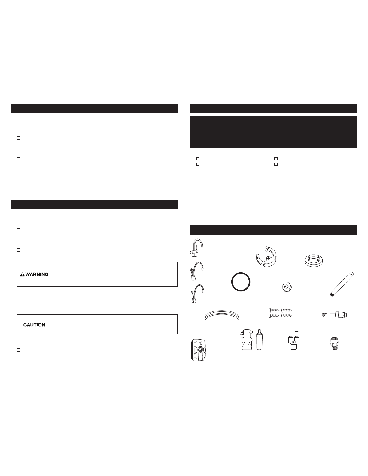
IN THIS PACKAGE
Filter Head & Cartridge
(SWT-FLTR only)
9.5mm White Tubes (2)
HC1100-1, -3
GN1100-1, -3
John Guest Fitting
(Australia only)
19mm Screws (4)
Y-Quick Connector
H3300-1, -3,
HC3300-1, -3
Semicircular
Mounting Plate
Rubber O-Ring
Hex Nut Hex Tool
Brass Seat
(HC3300, H3300)
SWT-FLTR-1, -3
SWT-3
Back Flow Protection Valve
(Australia/New Zealand only)
Plug (1)
■ For your satisfaction and safety, read all instructions, cautions and warnings before installing or using this
steaming hot water tap.
■ Make sure that all electrical wiring and connections conform to local codes.
■ A standard, earth (grounded) electrical outlet is required under the sink for the tap’s electrical power.
■ The wall outlet powering your tap must have electrical power supplied to it continuously.
■ This outlet must be fused and should not be controlled by the same wall switch that operates the food waste
disposer. Fuse/circuit breaker required is 10 amp for 230 volt (10 amp for 220-240 volt UK) and 15 amp for
120 v olt.
■ To ensure proper operation, this unit is not intended to be flushed with chlorine. If you suspect elevated levels
of chlorine in your water, it is recommended to use our water filtration system.
■ In Australia, all plumbing and electrical work must be completed by a qualified tradesperson.
■ To prevent damage or unit not operating properly, the water pressure must be between 172 kPa - 862 kPa
(1.7 bar - 8.6 bar; 25 psi - 125 psi) . Ambient (room) temperature between 10ºC and 38ºC. In Australia, an
Australian water mark approved 350 kPa set pressure limiting valve and dual check valve must be used.
■ Moving parts inside the tank causing a rattling noise is normal.
■ If the supply cord is damaged, it must be replaced by the manufacturer, its service agent or similarly qualified
persons in order to avoid a hazard.
WHAT YOU SHOULD KNOW BEFORE YOU BEGIN
ADDITIONAL CONSIDERATIONS
Equipment You May Need:
Equipment Required:
■ Drill
■ Compression fitting, T-fit ti ng
or saddle valve
■ Adjustable spanner
■ Anchors for plasterboard
■ Hole saw
■ Basin nut wrench
■ Hole punch
If you intend to use the sprayer hole in the sink for the hot water tap, you may need a 3.18mm plug or a 6.35mm
cap (not supplied) for the sink spray hose line. Se e Step 1B. If you need to cut a mounting hole in the stainless
steel sink, you may need a hole punch or a 35mm - 38mm hole saw made for cutting stainless steel.
What if you don’t have a sprayer hole or don’t want to use it?
Many householders replace the soap dispenser in their sink with a steaming hot water tap. If drilling a hole into a
stainless steel sink or worktop, you can cut a mounting hole for the tap with a hole saw for stainless steel, or you
can use a hole punch.
Hole size requirements: – HC1100, HC3300 and H3300, a 35mm - 38mm hole is required.
– GN1100, hole requirement is 32mm - 38mm.
Consult a professional before drilling into a surface other than stainless steel.
WHAT YOU NEED TO GET STARTED
■ Phillips and flat blade screwdrivers
■ Pencil
■ Tape Measure
■ Spirit level
In Australia and New Zealand, the installation must conform to AS3500.4.1 or AS/NZ S 3500.4.2 (Clause 9.b).
Important: Always arrange the power cord so that it cannot come in contact with hot surfaces.
■ Use this water heater only for its intended use as described in this manual.
■ This appliance is not intended for use by persons (including children) with reduced physical, sensor y or mental
capabilities, or lack of experience and knowledge, unless they have been given supervision or instruction
concerning use of appliance by a person responsible for their safety. Children should be supervised to ensure
that they do not play with hot water tap. To reduce the risk of injury, close supervision is required when an
appliance is used near children.
■ Do not operate this product if it has been or appears to be damaged in any manner or after the product
malfunctions, or is dropped. Return the complete product immediately to your retail dealer for inspection, and
if necessar y, adjustment or repair.
■ Do not disconnect the product from the power supply by pulling on the cord.
■ Do not use the product for other than its intended use as described in these instructions. The use of accessory
attachments other than those recommended by the manufacturer may cause safety hazards.
■ The recommended connection may be made to an existing cold water line with a branch terminating with a
shutoff valve, a pressure relief and dual check non-return valve sited adjacent to the product.
■ The filter is attached to cold water only.
■ Systems certified for cyst reduction may be used on disinfected water that may contain filterable cysts.
■ The filter is made in the USA.
Electric Shock Hazard: To reduce the risk of electric shock, do not immerse or expose
the product, flexible cord or plug to rain, moisture or any liquid or when standing in
or on damp or wet surfaces. If any electrical product falls into water, UNPLUG it
immediately. DO NOT RE ACH INTO THE WATER. Important: Prior to reconnecting to
the power supply, the product should be inspected by a qualified technician.
Property Damage: The flexible vent and outlet tubes must be correctly
connected to the tap supplied by the manufacturer. They must not be obstructed
or connected to a normal type tap or any other type. Important: Do not allow the
unit to continuously boil.
2
Page 3

Property Damage: Do not pinch or b reak copper tubing.
Do not distor t the last 25mm of tub ing.
HC110 0/G N1100
■ Unpack hot water tap components.
■ On a firm, flat surfa ce, carefully
straighten the copper tubing.
A
These instructions are separated
into main sections, indicated by
numbers, and subsections,
indicated by capital letters. The
manual is set-up this way to
allow you to take a break at any
point after completing a section
or subsection without affecting
the installation process.
Provides a step-by-step narrative describing the installation step, with tick boxes that can be marked as you
progress through the installation.
Contains simple illustrations that provide visual instruction to support the narrative.
CAUTIONS and WARNINGS that will require your attention during the step.
1
2
3
1
2
3
HOW TO USE THIS INSTRUCTION MANUAL
OVERVIEW OF A COMPLETED SET-UP
B
PREPARATION
START HERE
PROPER INSTALLATION SHOULD TAKE ABOUT 2-4 HOURS
■ Identify locations for the tap, tank and
filter (if applicable).
■ Check to make sure there is proper
clearance (see chart at left) for tap
handles to be fully opened.
■ Check to make sure counter is not too
thick (see chart at left).
■ Make sure there is an earth (grounded)
electrical outlet under the sink.
■ Tur n off water supply.
■ If using the sink sprayer hose hole,
remove nut that connects sprayer hose
at bottom of tap.
■ Using adjustable spanner, remove nut
connecting sprayer washer flange in
sprayer hole.
■ Close hose opening with either a plug
or a cap (not supplied).
1
The wall out let for the tap must have power
supplied to it continuously and must be fused.
It should not be controlled by the same wall
switch that operates the food waste disposer.
If you have to dr ill through sink or
worktop, you may need to rent or
purchase the appropriate tools.
Require d minimum from cent re of hole to wall
Maximum counter thickness is 76mm.
A
3
A potentially hazardous situation, which, if not avoided, could result in death or serious injury.
Caution, used with the safety alert symbol, indicates a hazardous situation which, if not
avoided, could result in minor or moderate injury.
Caution, without the safety alert symbol, is used to address practices not related to
personal injury.
Property Damage: Do not pinch or break copper tubing.
Do not distort the last 25mm of tubing.
HC1100 /GN1100
■ Unpack hot water tap components.
■ On a firm, flat surface, carefully
straighten the copper tubing.
■ Ensure that the black O-ring is properly
seated in the base of the tap head (the
groove on the underside of the tap).
A
INSTALLING THE TAP - HC1100 / G N110 0
2
HC1100 /GN1100
■ Feed tubes down through the hole
in the sink or countertop until the base
is at rest.
■ From under the sink, place the
semi-circular mounting plate and hex
nut onto the threaded stud. Ensure tap
head is at desired angle.
■ Insert screwdriver into hole on side of
hex tool (creating a “T”), and use tool
to tighten nut and secure tap.
B
An assistant may be needed to hold
the tap in place while securing.
HC3300 ............. 64mm
H3300 ............... 64mm
HC 1100 ............. 67mm
GN 1100 ............. 83mm
Page 4

Property Damage: Do not pinch or break copper tubing.
Do not distort the last 25mm of tubing.
HC3300/H3300
■ Unpack hot water tap components.
■ The recommended installation for this
tap is the tap handle on the right.
The unique design allows the handle
to be fully functional when placed to
the right or left of the hot water tap.
Determine preferred handle placement
before installing.
A
INSTALLING THE TAP - HC3300/H3300
2
HC3300/H3300
■ Insert rubber O-ring into groove on
brass seat.
■ Place brass seat, O-ring side down,
over hole in sink or worktop.
HC3300/H3300
■ Holding brass seat in place, feed
tubes down through the hole in sink
or worktop until base touches
brass seat.
■ Rotate brass seat until the two retaining
studs fit into the holes on the tap base
and base sits firmly on brass seat.
HC3300/H3300
■ From under the sink, place the
semicircular mounting plate onto
the threaded stud.
■ Place hex nut onto the threaded stud.
Ensure tap handle is on preferred side
and that tap head is at desired angle.
■ Insert screwdriver into hole on side of
hex tool (creating a “T”), and use tool
to tighten nut and secure tap.
B
C
D
Wetting O-ring with water prior to
inserting into brass seat helps hold
ring in place during installation.
To ease feeding of tubes through hole, first
insert blue tube with quick-connect attachment
and then insert the remaining tubes.
Semi-circular mounting plate should
encircle all descending tubes and
extend beyond sink hole when tight.
4
Mount tan k vertically in an ar ea that allows clearance
on the underside of th e tank for drainage, if
necessary. DO NOT over-tighten screws.
■ Pre-drill 3mm pilot holes at marks.
■ Tur n screws into pre-drilled holes,
leaving 6.4mm exposed.
■ Hang the tank on the screws.
■ Tighten the screws with only 1/2
turn clockwise.
Screws provided are for use in wood studs or
cabinets only. Use wall anchors (not supplied)
for installation into plasterboard.
CONNECTING TAP TO TANK
MOUNTING THE TANK
■ Select a spot under the sink to mount
tank vertically within reach of both
plumbing and electrical connections.
The tank should be within 400mm or
less of tap water lines and within
760mm or less of a standard earth
(grounded) outlet.
■ While holding tank in place on the spot
selected for installation, use a pencil to
mark locations for 2 hanging screws.
Personal Injury/Property Damage: Tank must be
located within 400mm of tap and within 7 60mm or
less of a sta ndard earth (grounded) outlet. DO NOT
extend plumbing or electrical lines.
■ Without depressing the grey button,
place the snap-connect fitting at the
end of the blue tube onto the left
plastic fitting on the tank, pushing until
it clicks into place. (1)
■ Slip the flexible white tube over
barbed middle fitting and slide down
approximately 12mm. (2)
■ Slip the small white tube over the
far right smooth fitting and slide down
approximately 12mm. (3)
■ Visually check for pinched or
crimped tubes.
Hose clamps are not needed for any of the connections.
Tank must be
mounted level
to ensure
proper operation.
Leave 12mm for
hanging tank.
Property Damage: Pinched or blocked water lines
may cause damage to the water tank. Check to
make sure tubes are connected properly and are
pushed in as mentioned.
3
4
B
A
A
(1)(2) (3)
Page 5

■ Mark hole locations for filter head
and bracket in a spot that allows for
filter replacement.
■ Drill 3mm starter holes and attach
bracket to wall with wood screws,
turning until snug.
■ Remove red filter cap, insert filter
cartridge into filter head and twist
clockwise until “LOCK” arrow on the
filter aligns with arrow on bracket.
Personal Injury: Do not lo cate filter above an out let or other
electric al device. Install head an d bracket so that connec tions
require no stretching, kinking or pinching of tubing.
5
A
■ Determine length of tubing required,
then cut to length making sure the cut
is perpendicular and burr-free.
■ Insert a whit e 9.5mm tube into inlet
side of filter head until it stops. Press
in again to ensure a secure fit.
■ Insert the other white tube into outlet
side of filter head until it stops. Press
in again to ensure a secure fit.
Property Damage: Tube runs need to form to
the cabinet ’s contours to allow storage space with
no sharp bends. Tubes need clean, perpendicular,
burr-free cuts to ensure a true fit.
From water
supply line
To ta p
HC1100
From filter or
water supply line
■ HC1100 only: Remove plug from
“Y” quick connector by holding grey
release ring and gently pulling plug out.
■ Insert the copper tube(s) from the
tap into the 9.5mm to 6.35mm
quick-connector. Press in again to
ensure a secure fit.
■ Connect the w hite tube from the
right outlet on the filter head into the
quick-connector until it stops. Press
in again to ensure a secure fit.
Property Damage: Do not extend the
copper lines farther than the 40cm provided.
■ To redirect filter replacement water
discharge, place 150 mm clear tube
over vent hole on the left side of
filter head.
It is normal for approximately 60 ml of
water to discharge when filter is r emoved.
D
Discharge tube
From water
supply line
To ta p
INSTALLING FILTR ATION
5
Plug
Plug
B
C
HC3300, H3300,
GN1100
From filter or
water supply line
Scalding Hazard: The tap dispenses water up to
98ºC, which can instantly cause scalds or burns.
Use care when operating this appliance.
Scalding Hazard: The tap dispenses water up to
98ºC, which can instantly cause scalds or burns.
Use care when operating this appliance.
■ Tur n on the cold water supply.
■ Depress the tap’s HOT handle and hold
it until water flows from the spout. Run
the water for at least 3 minutes to flush
lines (both the hot and cold handles on
HC 110 0 independently).
■ Check all connections to ensure they are
tight and that there are no leaks.
■ Plug in tank and ensure that green light
on front of tank is illuminated.
Note: See box below for special
instructions on operation of HC3300
and H3300 taps.
Featuring two-step hot side activation with
automatic shut off and cool side two-step
activation, which keeps the tap open when
dispensing cool wa te r.
■ HC3300: To dispense instant hot wa te r,
first press down on the tap handle and
then push the handle backward in the
direction of the red indicator on the top
of the handle. To dispense cool wa te r,
first press down on the tap handle
and then pull the handle forward in the
direction of the blue indicator on the
handle.
Featuring two-step hot side activation with
automatic shut off.
■ H3300: To dispense instant hot water,
first press down on the tap handle and
then push the handle backward in the
direction of the red indicator on the top
of the handle.
Water will be cold at first. Allow 12-15 minutes for water to reach target temperature.
Gurgling or hissing is normal during the initial heating cycle.
FILL TANK & THEN CONNECT POWER
7
A
Operating Instructions for HC3300 and H3300 taps
Dispensing Hot Water
(HC3300, H3300)
Dispensing Cool Water
(HC3300)
Property Damage: Join remaining
tube to cold water supply only.
AUS/N Z: See ins tructio ns provided with valve kit
At the other end of the white tube from the filter,
press on the:
■ (UK/IRL) 9.5mm to 15mm quick-connector
and connect to a 15mm water supply.
■ (AUS/NZ) 3/8" to 1/4" bspt John Guest
fitting and connect to a female 1/4" bpst
fitting water supply.
■ Press in again to ensure a secure fit.
FINAL WATER CONNECTION
6
UK/IRL AUS/NZ
Back flow
protection valve
Wall mount
clip
A
Page 6

Electric Shock Hazard: To prevent electrical shock, disconnect power before servicing
unit. Use only a properly earthed (grounded) and polarized electric outlet.
Scalding Hazard: Do not all ow water
to boil. May result in severe burns.
■ Only use mild cleaners to clean the tap
and plastic components.
■ Cleaners with acids, abrasives, alkaline,
and organic solvents will result in
deterioration of the plastic components
and void the wa rr anty.
CLEANING THE TA P AND TANK
Anytime the steaming hot water tap is not used for
extended periods of time, unplug and drain unit. If
it is below freezing you will need to unplug the unit
and drain it.
■ Disconnect power from unit (unplug unit).
■ Push hot water tap lever and allow water
to flow until it is cool.
■ Shut the cold water tap off at the valve.
■ Disconnect tubes from the tank.
■ Unhook tank from wall.
■ Hold tank upside down and drain the
water into the sink.
■ Towel dry any water drippings from
tank area.
■ Reinstall tank to wall and
reconnect tubes.
■ Remove and discard filter cartridge,
if applicable.
■ To put back into working ord er, install
new filter cartridge (if applicable) and
turn on cold water supply at valve.
Depress the hot water dispenser faucet
lever and hold until water flows from the
spout. Reconnect the electrical cord.
Factory temperature pre-set is
96˚C. To reset the thermostat
to 96°C, turn the indicator one
notch to the right of vertical.
After adjusting, depress the tap
handle for 20 seconds for water
to re-heat to the new setting.
■ To adjust water temperature, turn
thermostat dial on the front of the tank
clockwise to increase temperature
or turn anticlockwise to decrease
temperature. Repeat if necessary.
All changes should be minimal.
Replace filter cartridge when there is an obvious
decrease in water flow to the tap or if there is an
objectionable taste or odour to the water.
When the inlet and outlet ports have been closed
and the filter’s internal pressure has been relieved,
water (about 60ml) will discharge from vent line.
If the new filter cartridge cannot be inserted,
insert the old one and turn until it stops, remove it
and then retry the new cartridge.
It is recommended that carbon filters be replaced
every 6 months.
FILT ER GUIDE AND REPLACEMENT
Filter replacement instructions:
■ Replace with an InSinkErator
®
fi lt er.
■ Place pan or dish towel under the filter to
catch water drainage during change.
■ Slowly turn the cartridge anticlockwise
completely until it stops (1/4 turn).
■ Pull cartridge straight down and discard.
■ Insert new cartridge into filter head.
■ Top surface of cartridge will become
flush with the bottom of the filter head
when fully engaged.
■ Tur n the cartridge clockwise until it stops
(1/4 turn).
■ Align the in/out arrow on the head and
bracket assembly to the in/out arrow on
the cartridge.
■ Open tap to expel trapped ai r.
■ Run water for 3 minutes before usage.
■ Regularly inspect the unit for any signs
of leakage. If there are signs of water
damage, immediately remove the unit
from service.
■ To avoid water damage from leakage,
replace all cut, loose or split tubing.
■ A drain pan, plumbed to an appropriate
drain or outfitted with a leak detector,
should be used in those applications
where any leakage could cause
property damage.
PROPERTY DAMAGE
SEASONAL STORAGE/DRAINAGE
CARE AND USE
approx. 96°C
ADJUSTING THE THERM OSTAT
6
Property Damage: To avoid water damage, replace any loose or split tubing. Periodically
inspect the unit for any signs of leakage and immediately remove from service any unit
suspected of leaking.
Personal Injury: This tank is a non-pressurised tank. DO NOT modify this system. DO
NOT close vent tube or connect other types of taps or valves to the tank. Use only the
InSinkErator tap supplied. Use only parts provided. Contact an authorised InSinkErator
Service agent for repairs or replacement components.
This appliance must be earthed (grounded). This steaming hot water tap is equipped with a cord that has a
grounding conductor and earth ground pin. The plug must be connected to an appropriate outlet that is properly
installed and earthed (grounded) in accordance with all local codes and ordinances. Do not modify the plug
provided with the appliance – if it will not fit the outlet, have a proper outlet installed by a qualified electrician.
Check with a qualified electrician or tradesman if you are in doubt as to whether the steaming hot water tap is
properly earthed (grounded).
Fire Hazard: To minimise possibility of fire, DO NOT store flammable items such as rags,
paper or aerosol cans near the tank. DO NOT store or use petrol or other flammable
vapours and liquids in the vicinity of this or any other appliance.
A steaming hot water tap, like any water heater, has a limited life and will eventually fail. To avoid
possible proper ty damage and per sonal injury, this steaming hot water tap should b e regularly
examined for leakage and/or corrosion and replaced when necessa ry. A drain pan, plumbed to
an appropriate dra in or outfitted with a le ak detector, should be used in those applications where
any leakage could cause property damage. To check for corrosion, examine the appearance of
the dispe nsed water in a clear glass once every three (3) mo nths. If ther e is any discoloration or
rusty appearance, unplug and drain unit as described in the Seasonal Storage /Drainage se ction
on page 6 of this manual. If the water discoloration remains after draining and refilling unit,
discontinue use and contact an authorized InSinkErator service agent.
Electric Shock Hazard: Using an ungrounded (no earth ground) or improperly
connected appliance can result in serious injury or death from electrical shock.
Page 7

Tap : 2-year warranty
SWT-FLTR (tank used with filter): 2-year warranty
SWT (tank used without filter): 1-year warranty
This warranty is provided by InSinkErator, a division of Emerson Ele ctric Co., (“InSinkErator” or “Manufacturer” or
“we” or “our” or “ us”) to the original consumer owner of the InSink Erator product with which this warr anty is provided
(the “InSinkErator Product”), and any subsequent ow ner of the residence in which the Product was originally installed
(“Customer” or “yo u” or “your”).
InSinkErator warrants to Customer that your InSinkErator Product will be free from defec ts in materials and workmanship,
subject to the exclusions described below, for the “Warranty Period”, commencing on the later of: (a) the date your
InSinkErator Product is originally installed, (b) the date of purchase, or (c) the date of manufacture as identified by yo ur
InSinkErator Product serial nu mber. You will be required to s how written documentation supporting (a) or (b). If you are
unable to provide documentation supporting either (a) or (b), the Warranty Pe riod commencement date will be determined
by Manufacturer, in its sole and absolute discretion, based upon your InSinkErator Product se rial nu mber.
What is Covered
This warranty covers defects in materials or workmanship, subject to the exclusions below, in InSinkErator Products used
by a consumer Custom er for residential use onl y, and includes all replacement parts a
nd labor costs. YOUR SOLE AND
EXCLUSIVE REMEDY UNDER THIS LIMITED WARRANTY SHALL BE LIMITED TO REPAIR OR REPLACEMENT OF THE
INSINKERATOR PRODUCT.
What is n ot Covere d
This limited war ranty does not extend to and expressly exc ludes:
• Losses or damages or the inability to operate your InSinkErator Product resulting from conditions beyond the
Manufacturer’s control including, without limitation, accident, alteration, misuse, abuse, neglect, negligence
(other than Manufacturer’s), fa ilure to install, maintain, assemble, or mount the InSinkErator Product in accordance
with Manufacturer’s instructions or local electrical and plumbing codes.
• Wear and tear expected to occur during the normal course of use, including without limitation, cosmetic rust,
scratches, dents or comparable and reasonably expected losses or damages.
In addition to the above exclusions, this warra nty does not apply to InSinkErator Products installed in a commercial or
industrial application.
No Othe r Express Warranty A pplies
This warranty is the sole and exclus ive warranty provided to the Cus tomer identified above. No other expres s warr anty,
written or ve rbal, applies. No employee, agent, dealer, or other person is au thorized to alter this limited warranty or make
any other warran ty on behalf of Manufacturer. The terms of this warrant y shall not be modified by the Manufacturer, the
original own er, or their r
espective successors or assigns.
What we will do to Correct Problems
If your InSinkErator Product does not ope rate in accordance with the documentation provided to yo u, or you have questions
concerning your InSinkErator Product or h ow to determine when service is needed, please see attached Service Agency List.
The following information must be provided as part of your war ranty claim: your name, address, p hone nu mber, yo ur
InSinkErator Product model and serial nu mber, and if necessary, upon request, writte n confirmation of either: (a) the date
shown on your installation re ceipt, or (b) the date shown on your purchase receipt.
Manufacturer or its authorize d service representative will determine, in its sole and absolute discretion, if your InSinkErator
Product is covered unde r this war rant y. You will be gi ven the contact information for your closest authorize d InSinkErator
Service Ce nter. Please contact your InSinkErator Service Center directly to rece ive in home warranty repair or replacement
service. Only an au thorized InSinkErator service representative may provide war ranty service. InSinkErator is not responsible
for warranty claims arising from work performed on you r InSinkErator Product by anyone other than an authori zed
InSinkErator service representative.
If a covered claim is made during the Warranty Period, Manufacturer will, through its author ized service representative, either
repair or replace your InSinkErator Product. Cost of re
placement parts or a new InSinkErator Product, and cost of labor for
repair or installation of the replacement InSinkErator Produc t are provided at no cost to you. Repair or replacement shall
be determined by Manufacturer or its autho rized service representative in their sole discretion. All repair and replacem ent
services will be provided to you at your ho me. If Manufacturer determines that your InSinkErator Product must be replaced
rather than repaired, the warra nty on the replacement InSinkErator Product will be limited to the unexpired term remaining in
the original Warra nty Period.
Limitation of Liability
TO THE EXTENT PERMITTED BY LAW, IN NO EVENT SHALL MANUFACTURER OR ITS AUTHORIZED SERVICE
REP RESE NTATIV ES BE LIABLE FOR ANY INCIDENTAL, SPECIAL, INDIRECT, OR CONSEQUENTIAL DAMAGES, INCLUDING
ANY ECONOMIC LOS S, WHETHER RESULTING FROM NONPERFORMANCE, USE, MISUSE OR INABILITY TO US E THE
INSINKERATOR PRODUCT OR THE MANUFACTURER’S OR ITS AUTHORIZED SERVICE RE PRESE NTATIV E’S NEGLIGENCE.
MANUFACTURER SHALL NOT BE LIABLE FOR DAMAGES CAUSED BY D ELAY IN PERFORMANCE AND IN NO EV ENT,
REGARDLESS OF THE FORM OF THE CLAIM OR CAUS E OF ACTION (WHETHER BASED IN CONTRACT, INFRINGEMENT,
NEGLIGENCE, STRICT LIABILITY, OTHER SORT OR OTHERWISE), SHALL MANUFACTURER’S LIABILITY TO YOU E XCEED
THE PRICE PAID BY THE ORIGINAL OWNER FOR THE INSINKERATOR PRODUCT.
The term "consequential damages" shall include, bu t not be limited to, loss of anticipated profits, business interruption, loss
of use or revenue, cost of capital or loss or damage to property or e quipment.
WARRANTY INFORMATION TROUBLESHOOTING
WHAT TO DO
Water and steam
spits forcefully from
spout without turning
on the tap.
• Unit is b oiling.
May be normal during initial set-up.
• Depress tap lever to release some water from the tank.
• Adjus t water temperature using dial on tank front.
Remember that at higher a ltitudes, water boils at
lower temperatures.
Water is not hot . • The unit may not be plugged i n.
• The electric outlet is inoperative.
• Make sure the unit is connected to a properly earthed
(grounded) electric outlet.
• Make sure the circuit breaker or fuses are
functioning properly.
• Check t hat the outlet is not switched off.
Water is too hot
or not hot enough.
• Thermostat is not adjusted to
your needs.
• Adjust the thermostat slowly, then depress or twist tap
handle for 20 seconds to bring in fresh water to be heated
at the new set ting. Allow 5-7 minutes for water to reach
new temperature.
Water comes out of vent
instead of spout
• Outlet tube is blocked. • Check t hat outlet tube is not kinked, twisted or pinched.
• Unscrew spout end piece and clean out any debris.
Water is dripping
from the spout/vent
intermittently.
• The expansion chamber is not
draining properly due to low
water pressure.
• The spo ut is blocked.
• Unplug the unit. If the dripping does not stop after a few
minutes, check the supply valve to ensure it is fully open
and there are no obstructions in the water line reducing
the pressure below 172 kPa (1.7 bar; 25 psi). i.e., a poorly
mounted saddle valve, a clogg ed water filter, or a partially
opened shut-off valve.
• Unscrew spout end piece and clean out any debris.
Water is dripping
from the spout/vent
constantly.
• Debris in the water line may be
in the tap valve seat causing a
slow water leak.
• Unscrew spout end piece and clean out any debris.
• Depress or twist lever 7-10 times to flush tap & lines.
Divided stream.
• Debris in the end piece. • Unscrew spout end piece and clean out any debris.
PROBLEM POSSIBLE CAUSE
LED green light on
front of tank does
not illuminate.
• The unit may not be plugged i n.
• The electric outlet is inoperative.
• Make sure that the circuit breaker or fuses are
functioning properly.
• Check t hat the outlet is not switched off.
Water discoloration /
rusty appearance.
• Corrosion of unit. • Unplug and drain as described in the Sea sonal Storage/
Drainage Section on page 6 of t his manual. If the water
discoloration remains af ter draining and refilling unit,
discontinue use and contact an authorised InSinkErator
service agent.
FILTRATION ISSUES
Water taste or odour.
New filter does not fit.
The filter leaks.
No water flow or low
water flow.
• Filter water flow direction is wrong.
• Filter needs to be flushed out.
• Life of filter has expired.
• Head and bracket not fully rotated.
• Filter O-ring breach.
• Head and bracket not fully rotated.
• Filter O-ring breach.
• Life of filter has expired.
• Review filter tube connection instructions.
• Depress or twist t he tap and run until the water is cold.
• If there is no change, replace filter cartridge.
• Take out the new filter, put in old filter.
• Remove, inspect, reinstall filter cartridge.
• Test unit by reinstalling old filter and rotating to full stop.
Check for leaks.
• Replace filter cartridge. See page 6.
7
Page 8

InSinkErator Division
Emerson Electric Co.
4700 21st Street
Racine, WI 53406-5093
USA
Sales/Service Tel: 262-554-3652
www.insinkerator.com/worldmap.html
InSinkErator Division
Suite 6, Building 6
Hatters Lane, Croxley Green Business Park
Watford WD18 8YH
United Kingdom
Sales Tel: (0) 1 923 297 880
Service Tel: (0) 800 389 3715
www.insinkerator.co.uk
InSinkErator Division
471 Mountain Highway
Bayswater Vic 3153, Australia
Sales Tel: 61 03 9720 5599
Service Tel: 1 300 136 205
www.insinkerator.com.au
Parex Industries Ltd.
5 Tolich Place, Henderson
P.O. Box 21-102
Auckland, New Zealand 0610
Sales Tel: 64 9 836 6566
Service Tel: 0800 200 510
www.parex.co.nz
KAL Group
4078 Kingswood Road,
Citywest Business Park
Dublin, Ireland
Tel: 01 413 6481, 01 413 6400
Fax: 01 413 6464
Email: info@kal.ie
Emerson Trading (Shanghai) Co., Ltd.
InSinkErator China Operations
11th Floor, Innov Tower
1801 Hong Mei Road, XuHui District
Shanghai 200233, P.R. China
Fax: 86-21-3367-8121
www.insinkerator.com.cn
Emerson Electric de Mexico, S.A. de C.V.
Calle 10 No. 145
Colonia San Pedro de los Pinos
Delegación Álvaro Obregón
Código Postal 01180
México D.F.
Sales/Service Tel: 52 (55) 5809 5099
www.insinkerator.es
Emerson FZE
Jebel Ali Free Zone
InSinkErator – MEA
P.O. Box 17033
Dubai, United Arab Emirates
Sales Tel: 9714 8118282
Service Tel: 971 55 498 3985
Email: Mohamed.Karam@emerson.com
The Emer son logo is a tradem ark and servic e mark of Emerson El ectric Co. Printed i n U.S.A.
InSinkErator
®
may make improvements and/or changes in the specifi cations
at any time, in i ts sole discreti on, without notice o r obligation and fu rther
reser ves the right to chang e or discontinue mo dels.
© 2011 InSinkErator, InSinkErator
®
is a divisi on of Emerson Elec tric Co. All Rights Re served.
44445 REV A
www.insinkerator.com/worldmap.html
 Loading...