

Page 1
Emerson FB2200 Flow Computer Instruction Manual
Emerson FB2200 Flow Computer
Instruction Manual
D301784X012
November 2020
Remote Automation Solutions
Page 2

Emerson FB2200 Flow Computer Instruction Manual
D301784X012
November 2020
Device Safety Considerations
Reading these Instructions
Before operating the device, read these instructions carefully and understand their safety implications. In some
situations, improperly using this device may result in damage or injury. Keep this manual in a convenient location
for future reference. Note that these instructions may not cover all details or variations in equipment or cover
every possible situation regarding installation, operation, or maintenance. Should problems arise that are not
covered sufficiently in the text, immediately contact Customer Support for further information.
Protecting Operating Processes
A failure of this device – for whatever reason -- may leave an operating process without appropriate protection and
could result in possible damage to property or injury to persons. To protect against this, you should review the
need for additional backup equipment or provide alternate means of protection (such as alarm devices, output
limiting, fail-safe valves, relief valves, emergency shutoffs, emergency switches, etc.). Contact Remote
Automation Solutions for additional information.
Returning Equipment
If you need to return any equipment to Remote Automation Solutions, it is your responsibility to ensure that the
equipment has been cleaned to safe levels, as defined and/or determined by applicable federal, state and/or local
law regulations or codes. You also agree to indemnify Remote Automation Solutions and hold Remote
Automation Solutions harmless from any liability or damage which Remote Automation Solutions may incur or
suffer due to your failure to ensure device cleanliness.
Grounding Equipment
Ground metal enclosures and exposed metal parts of electrical instruments in accordance with OSHA rules and
regulations as specified in Design Safety Standards for Electrical Systems, 29 CFR, Part 1910, Subpart S, dated: April
16, 1981 (OSHA rulings are in agreement with the National Electrical Code). You must also ground mechanical or
pneumatic instruments that include electrically operated devices such as lights, switches, relays, alarms, or chart
drives.
Important: Complying with the codes and regulations of authorities having jurisdiction is essential to ensuring
personnel safety. The guidelines and recommendations in this manual are intended to meet or exceed applicable
codes and regulations. If differences occur between this manual and the codes and regulations of authorities
having jurisdiction, those codes and regulations must take precedence.
Protecting from Electrostatic Discharge (ESD)
This device contains sensitive electronic components which be damaged by exposure to an ESD voltage.
Depending on the magnitude and duration of the ESD, it can result in erratic operation or complete failure of the
equipment. Ensure that you correctly care for and handle ESD-sensitive components.
System Training
A well-trained workforce is critical to the success of your operation. Knowing how to correctly install, configure,
program, calibrate, and trouble-shoot your Emerson equipment provides your engineers and technicians with the
skills and confidence to optimize your investment. Remote Automation Solutions offers a variety of ways for your
personnel to acquire essential system expertise. Our full-time professional instructors can conduct classroom
training at several of our corporate offices, at your site, or even at your regional Emerson office. You can also
receive the same quality training via our live, interactive Emerson Virtual Classroom and save on travel costs. For
our complete schedule and further information, contact the Remote Automation Solutions Training Department
at 800-338-8158 or email us at education@emerson.com.
Ethernet Connectivity
This automation device is intended to be used in an Ethernet network which does not have public access. The
inclusion of this device in a publicly accessible Ethernet-based network is
ii Contents
not recommended.
Page 3

Emerson FB2200 Flow Computer Instruction Manual
D301784X012
November 2020
Contents
Section 1: Introduction 1
1.1 Safety Labels ......................................................................................................................................... 3
1.2 Features ................................................................................................................................................ 3
1.3 FB2200 Flow Computer Models ............................................................................................................. 4
1.3.1 FB2200 Flow Computer – With Sensor ..................................................................................... 4
1.3.2 FB2200 Flow Computer – No Integral Sensor ............................................................................ 5
Central Processing Unit (CPU) ............................................................................................................... 5
1.4
1.4.1 Memory ................................................................................................................................... 5
1.5 Inputs & Outputs (I/O) ........................................................................................................................... 5
1.6 Power Options ...................................................................................................................................... 7
1.7 Communications .................................................................................................................................. 7
1.8 Human-Machine Interface (HMI) Module .............................................................................................. 8
1.9 FBxWifi™ Communications ................................................................................................................... 8
1.10 Software Tools ...................................................................................................................................... 9
1.11 RoHS2 Compliance ............................................................................................................................... 9
1.12 Physical Security ................................................................................................................................... 9
Section 2: Installation 13
2.1 Hazardous Locations ........................................................................................................................... 13
2.2 Environmental Specifications .............................................................................................................. 13
2.3 Required Tools .................................................................................................................................... 14
2.4 Site Considerations ............................................................................................................................. 15
2.5 General Wiring Guidelines ................................................................................................................... 20
2.6 Grounding .......................................................................................................................................... 21
2.7 Opening/Closing the Enclosure ........................................................................................................... 21
2.8 Mounting the Enclosure ...................................................................................................................... 22
2.8.1 Bolting Considerations ........................................................................................................... 22
2.8.2 O-rings with Flange Adapters ................................................................................................. 25
2.8.3 Pole Mounting – Aluminum Enclosure .................................................................................... 26
2.8.4 Pole Mounting – Fiberglass Enclosure ..................................................................................... 27
2.8.5 Panel/Wall Mounting Dimensions – Aluminum Enclosure ....................................................... 28
2.8.6 Panel/Wall Mounting Dimensions – Fiberglass Enclosure ........................................................ 29
2.8.7 Rotating the Housing ............................................................................................................. 31
2.9 Power Modes ...................................................................................................................................... 32
2.9.1 Low Power Mode .................................................................................................................... 32
2.9.2 Standard Power Mode ............................................................................................................ 33
2.9.3 Notes on Battery Life .............................................................................................................. 34
2.10 Connecting Power ............................................................................................................................... 35
2.10.1 Connecting DC Power ............................................................................................................ 35
2.10.2 Connecting Battery Power ..................................................................................................... 36
2.10.3 Connecting Solar Power ......................................................................................................... 44
2.11 Installing the Optional 30W Solar Panel ............................................................................................... 50
2.12 Adjusting the Optional Solar Panel ...................................................................................................... 52
2.13 Connecting Communication Ports ...................................................................................................... 54
2.13.1 Connecting to COM1 ............................................................................................................. 54
2.13.2 Connecting to COM2 and COM3 ............................................................................................ 57
2.13.3 Connecting to Ethernet .......................................................................................................... 59
2.14 Security Intrusion Switch ..................................................................................................................... 61
Contents iii
Page 4

Emerson FB2200 Flow Computer Instruction Manual
D301784X012
November 2020
Section 3: I/O Configuration and Wiring 63
3.1 Analog Inputs ...................................................................................................................................... 65
3.1.1 AI Wiring ................................................................................................................................ 67
3.2 Analog Outputs ................................................................................................................................... 68
3.2.1 AO Wiring .............................................................................................................................. 69
3.3 Digital Inputs ...................................................................................................................................... 70
3.3.1 DI Wiring................................................................................................................................ 71
3.4 Digital Outputs ................................................................................................................................... 72
3.4.1 DO Wiring .............................................................................................................................. 72
3.5 Pulse Inputs ........................................................................................................................................ 75
3.5.1 PI Wiring ................................................................................................................................ 76
3.6 Connecting the RTD/PRT ..................................................................................................................... 76
3.7 Connecting a Rosemount 4088B ......................................................................................................... 78
3.8 Wiring a Digital Output to the Optional Relay ...................................................................................... 81
3.9 Radio Wiring ....................................................................................................................................... 82
Section 4: Operation 83
4.1 Powering Up/Powering Down the Device ............................................................................................ 83
4.2 Establishing Communications ............................................................................................................. 83
Communicating with the SCADA Host.................................................................................... 83
4.2.1
4.2.2 Communicating with a Laptop Using One of the Serial Ports ................................................... 84
4.2.3 Communicating with a Laptop Using Ethernet ....................................................................... 84
4.2.4 Communicating with a Laptop Wirelessly with FBxWifi ........................................................... 85
4.3 Communicating Using the HMI Module ............................................................................................... 86
Section 5: Service and Troubleshooting 89
5.1 Returning the Unit for Repairs ............................................................................................................. 91
5.2 Interpreting the Status LEDs ................................................................................................................ 91
5.3 Switch and Buttons ............................................................................................................................. 93
5.4 Removing/Replacing the HMI Module ................................................................................................. 94
5.5 Replacing the Main Battery Pack.......................................................................................................... 94
5.6 Removing/Replacing the SRAM Battery ............................................................................................. 104
5.7 Upgrading System Firmware ............................................................................................................. 107
Appendix A: Special Instructions for Class I Division 2 Locations 109
Appendix B: ATEX Non-Sparking Zone 2 Certifications 113
Index 115
iv Contents
Page 5

Section 1: Introduction
This section covers the following topics:
Safety Labels
Features
FB2200 Flow Computer Models
Central Processing Unit (CPU)
Inputs & Outputs (I/O)
Power Options
Communications
Human-Machine Interface (HMI) Module
FBxWifi™ Communications
Software Tools
Emerson FB2200 Flow Computer Instruction Manual
D301784X012
November 2020
RoHS2 Compliance
Physical Security
The Emerson FB2200 Flow Computer measures pressure, differential pressure, and temperature
for one or two meter runs of natural gas. It works with both differential pressure-based meters
measuring static pressure (SP), differential pressure (DP), and temperature (T), and linear meters
measuring pulse or analog inputs, SP, and T.
This manual describes how to install and configure the Emerson FB2200 flow computer hardware.
For information on using the FBxConnect™ configuration software, see the online help that
accompanies FBxConnect.
Introduction 1
Page 6
Emerson FB2200 Flow Computer Instruction Manual
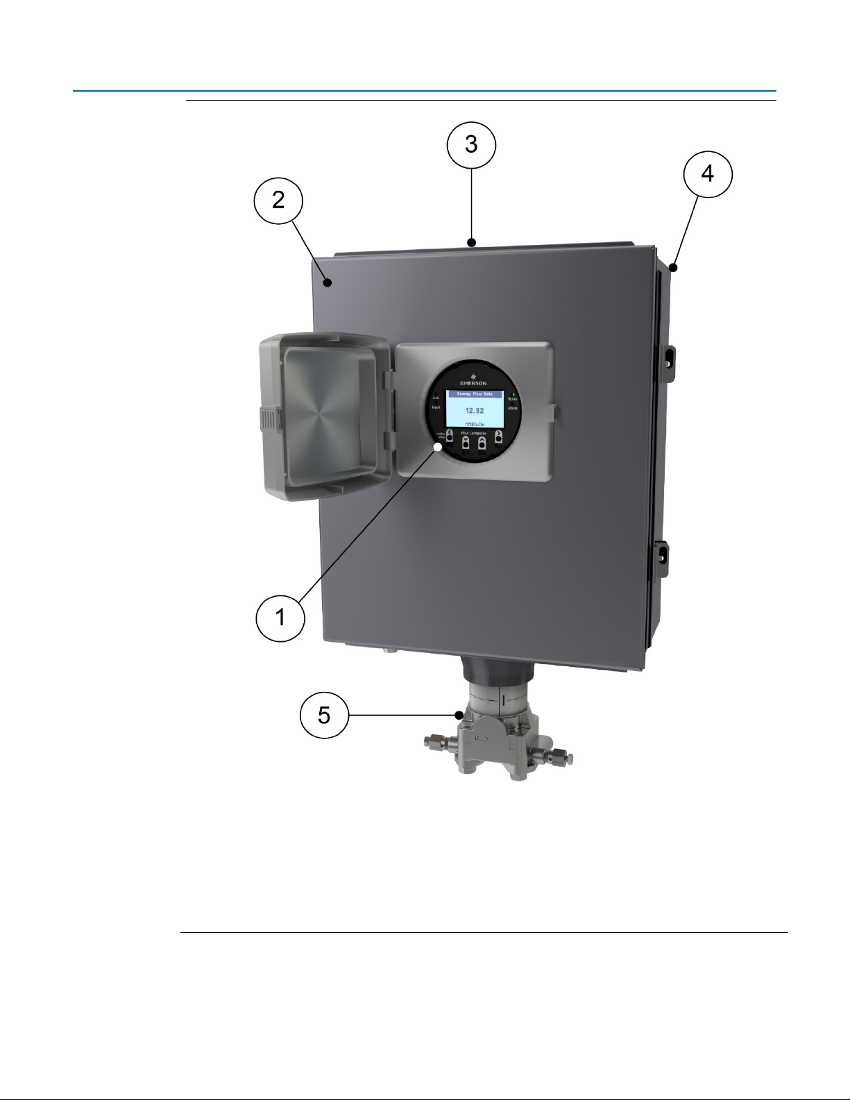
1
HMI module
2
Front cover
3
Data plate
4
Enclosure
5
Sensor module
D301784X012
November 2020
Figure 1-1. FB2200 Flow Computer
2 Introduction
Page 7

1.1 Safety Labels
DANGER
WARNING
CAUTION
SAFETY FIRST
This product may display safety label(s) to identify potential hazards. The same types of notices
appear within the documentation. Whenever you see an exclamation point (!) enclosed within a
triangle (shown to the left), consult the documentation for additional safety information about the
hazard and how to avoid it. The labels used are:
Emerson FB2200 Flow Computer Instruction Manual
D301784X012
November 2020
MAY CAUSE DEATH
Observe all precautionary signs posted on the equipment.
Failure to do so may result in death or serious injury to personnel.
DANGER TO PERSONNEL AND EQUIPMENT
Observe all precautionary signs posted on the equipment.
Failure to do so may result in injury to personnel or cause damage to the equipment.
MAY CAUSE INJURY TO PERSONNEL OR DAMAGE EQUIPMENT
Observe all precautionary signs posted on the equipment.
Failure to do so may result in injury to personnel or cause damage to the equipment.
1.2 Features
Introduction 3
General instructions and safety reminders.
The FB2200 flow computer includes the following key features:
Enclosure suitable for use in Class I Division 2 non-incendive and Ex nA Zone 2 non- sparking
environments. Enclosure available in either aluminum or compression-molded fiberglass
Optional Integral multi-variable sensor for measurement of Pressure (P) and Differential
Pressure (DP)
Optional static pressure sensor, typically used with linear meters
Connections for customer-supplied resistance temperature detector (RTD) for measurement
of temperature (T)
Base I/O consists of two on-board channels you can individually configure as digital input
(DI), digital output (DO), or pulse input (PI) and two on-board I/O channels you can
Page 8
Emerson FB2200 Flow Computer Instruction Manual
D301784X012
November 2020
individually configure as either analog input (AI) or analog output (AO). Optional expansion
I/O modules are available.
Power from a DC power supply or an optional lead acid battery/solar panel combination
Serial communication options for RS-232, RS-485/422 (4-wire), and RS-485 (2-wire)
Optional 10/100 Base T-Ethernet port
HMI module with optional display and back light for local operator interaction
Optional Wi-Fi
computer from a laptop without physical cable connection
Application software supports AGA3, AGA8, ISO 5167, ISO 6976, and API 21.1 calculations in
either U.S., metric, or other natural gas standard units
®
transceiver (802.11 b/g) enabling a field technician to access the flow
1.3 FB2200 Flow Computer Models
You can purchase two basic models of the FB2200 flow computer. In addition, each model is
available in either an aluminum enclosure or a compression-molded fiberglass enclosure.
Either model includes two ¾ in NPT pipe-threaded conduit ports on the bottom of the enclosure to
permit entry of field conduit for I/O and communication wiring.
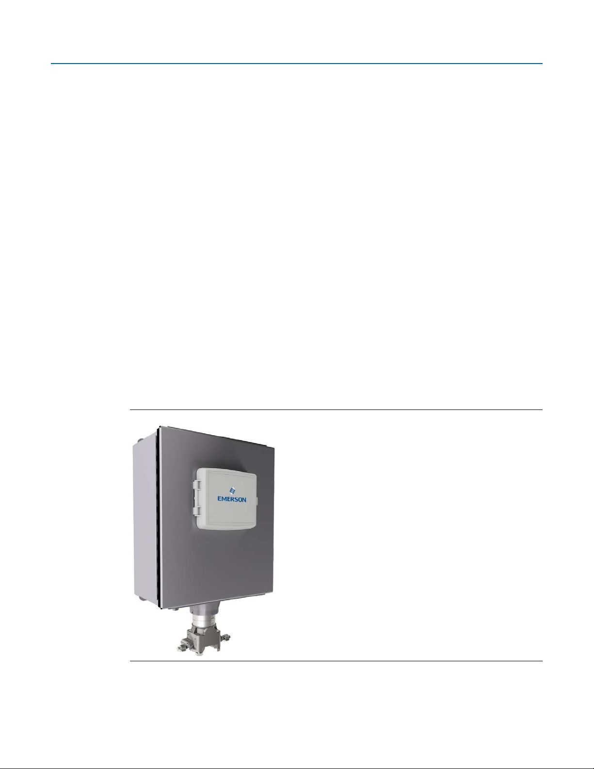
1.3.1 FB2200 Flow Computer – With Sensor
This version includes either a multi-variable (MV) sensor module (Figure 1-2) or a static pressure
sensor module (not shown).
Figure 1-2. FB2200 Flow Computer – Multivariable Sensor Version
4 Introduction
Page 9

Emerson FB2200 Flow Computer Instruction Manual
Memory
Usage
8 MB SRAM
Holds in-use configuration, current state of all variables
Holds firmware image, historical logs, configuration backup (if saved to flash),
1.3.2 FB2200 Flow Computer – No Integral Sensor
The no integral sensor version includes no sensor module. In this case the process variable data
used in flow computer calculations comes from external devices and enters the device through the
serial ports or I/O channels.
Figure 1-3. FB2200 Flow Computer – No Integral Sensor Version
D301784X012
November 2020
1.4 Central Processing Unit (CPU)
The flow computer’s CPU is a NXP® Kinetis® K61 series CPU with an ARM® Cortex® M4 processor
that operates at 4 to 60 MHz depending on the power mode. The CPU runs the Micrium operating
system.
1.4.1 Memory
The flow computer includes both static and flash memory.
Table 1-1: Memory
128 MB Flash
and the executing program
1.5 Inputs & Outputs (I/O)
The flow computer comes with base I/O from both the CPU and the built-in multi-variable (MV)
sensor.
Base I/O consists of:
Introduction 5
Page 10

Emerson FB2200 Flow Computer Instruction Manual
FB2200 Base Unit
FB2200 purchased with 8channel Expansion I/O Module
FB2200 purchased with 8-channel
Expansion I/O Module and 6channel Expansion I/O Module
MV Sensor (P, DP) or
MV Sensor (P, DP) or Static
MV Sensor (P, DP) or Static
2 DI/DO/PI channels
6 DI/DO/PI channels (4 residing
10 DI/DO/PI channels (4 residing
2 AI/AO channels
6 AI/AO channels (4 residing on
8 DI/DO channels (4 residing on
D301784X012
November 2020
Pressure (P) input from the MV sensor, differential pressure (DP) input from the MV sensor,
connections for temperature (T) input from a customer-supplied RTD/PRT -or – a single
Static Pressure Sensor with RTD/PRT connections. Alternatively, you can purchase the flow
computer without an integral sensor.
Two on-board I/O channels that you can individually configure as digital input (DI), digital
output (DO), or pulse input (PI)
Two on-board I/O channels that you can individually configure as either analog input (AI) or
analog output (AO)
An optional 8-channel expansion I/O board includes:
Four I/O channels that you can individually configure as digital inputs (DI), digital outputs
(DO), or pulse inputs (PI)
Four I/O channels that you can individually configure as either analog inputs (AI) or analog
outputs (AO)
If the optional 8-channel expansion I/O board is present, the device can optionally support an
additional 6-channel expansion I/O board which includes:
Four I/O channels that you can individually configure as digital inputs (DI), digital outputs
(DO), or pulse inputs (PI)
Two I/O channels that you can individually configure as either analog inputs (AI) or analog
outputs (AO)
Table 1-2. FB2200 I/O Configurations
Static Pressure (SP)
Sensor
Connections for
customer-supplied 2-,
Pressure (SP) Sensor
Connections for customersupplied 2-, 3-, or 4-wire
RTD/PRT
Pressure (SP) Sensor
Connection for customersupplied 2-, 3-, or 4-wire
RTD/PRT
3-, or 4-wire RTD/PRT
on the 8-channel expansion I/O
module).
on the 8-channel expansion I/O
module and 4 residing on the 6channel expansion I/O module)
6 Introduction
the 8-channel expansion I/O
module).
the 8-channel expansion I/O
module and 2 residing on the 6channel expansion I/O module)
Page 11

1.6 Power Options
Option
Usage
External DC Power
Lead Acid Battery Pack
12 Vdc
Port
Type
Use
COM1
Serial communications
RS-232, RS-485/422 (4-wire), or RS-485
COM2 Serial communications
RS-232 or RS-485 (2-wire)
COM3 Serial communications
RS-232 or RS-485 (2-wire)
You can power the flow computer using an external DC input, or an internal rechargeable battery
connected to a solar panel.
Important
Use only batteries supplied with the flow computer or sold by Emerson Remote Automation
Solutions as spare parts for this flow computer. If you substitute a battery you obtain elsewhere
you will void your certification unless it is the identical part from the same manufacturer as that
supplied with the flow computer from Emerson.
Table 1-3. Power Options
Emerson FB2200 Flow Computer Instruction Manual
D301784X012
November 2020
Supply
10.5 Vdc to 30 Vdc external supply (Max power at 10 watts)
1.7 Communications
The flow computer includes three serial communication ports and one Ethernet port. The serial
ports allow communication using DNP3, Modbus, BSAP, and ROC protocols. The Ethernet port is an
RJ-45 connector; the FB2200 supports a maximum of six concurrent TCP connections (sockets)
through this port.
Table 1-4. Serial Ports
Software-selectable for RS-232, RS485/422 (4-wire), or RS-485 (2-wire)
operation
4-wire
10.5 Ah
Not suitable with ATEX or IECEx applications
Optional solar panel and charge controller to charge battery
(supplied separately)
(2-wire) communication to host or other
devices. 4-wire used with external radio.
Introduction 7
Software-selectable for RS-232 or RS-485
(2-wire) operation
2-wire
Software-selectable for RS-232 or RS-485
(2-wire) operation
2-wire
communication to host or other
devices.
communication to host or other
devices.
Page 12
Emerson FB2200 Flow Computer Instruction Manual
D301784X012
November 2020
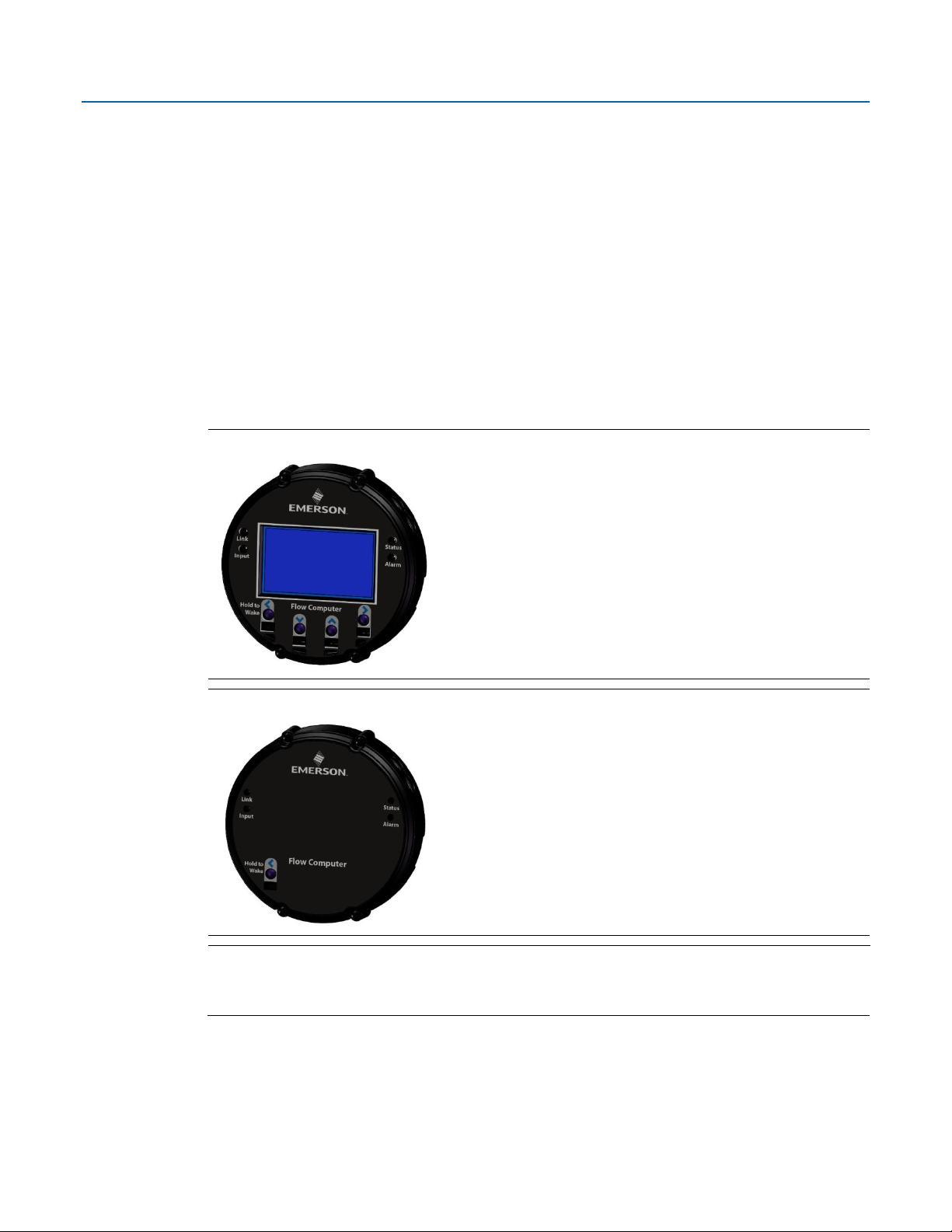
1.8 Human-Machine Interface (HMI) Module
The flow computer includes an HMI module with an optional liquid crystal display (LCD) for local
operator access to the device. The LCD, if present, shows a series of menus that sequentially
displays the current values of particular process variables. A configuration parameter in
FBxConnect determines whether you must first log in to view the menus. If required, you log in by
selecting alphanumeric characters by scrolling through a list until you select the correct character.
The HMI module includes four LEDs to provide status information. Units with the display include
four infrared (IR) buttons for operator interaction.
To conserve power the HMI module enters sleep mode after a period of inactivity. Sleep mode
disables FBxWifi communication. In FBxConnect, you can configure the number of minutes of
inactivity triggering sleep mode through the LCD Sleep Time parameter. Setting this parameter to
0 disables sleep mode which keeps the HMI module on but uses significantly more power.
Figure 1-4. HMI Module with LCD
Figure 1-5. HMI Module without LCD
Note
If your flow computer does not include the LCD option (shown in Figure 1-4), you still have the
status LEDs and a single IR button for waking up the device (shown in Figure 1-5).
1.9 FBxWifi™ Communications
The flow computer has an optional Wi-Fi® transceiver (FBxWifi) that enables you to connect via a
laptop or tablet from a distance. The distance supported varies depending on the laptop/tablet
8 Introduction
Page 13

type and environmental conditions but is typically 70 to 100 feet from the front of the flow
computer and 40 to 60 feet from the side and rear of the flow computer.
This capability allows an operator to potentially remain outside the hazardous location and still
communicate with the flow computer. The operator's laptop must have Wi-Fi capability, line-ofsight access to the HMI module, and must be loaded with FBxConnect configuration software.
Once connected, the operator can view process values, edit configuration parameters, and collect
logs.
Note
The FBxWifi electronics reside inside the HMI module. The HMI module must be awake to use
FBxWifi communications You can wake it up manually by holding a finger against the front cover
glass over the Hold to Wake button (the left-most button) for typically from five to ten seconds.
1.10 Software Tools
The FBxConnect configuration software provides a series of wizards that allow you to perform
configuration activities for the flow computer. You connect a PC running the FBxConnect
configuration software to the flow computer using one of the communication ports or through a
wireless connection. You can then:
Emerson FB2200 Flow Computer Instruction Manual
D301784X012
November 2020
Set parameters within your application
Configure I/O channels
Specify the serial communication method for a port (RS-232 to RS-485) as needed
View or collect audit trail information such as alarm, event, or historical logs
Update system firmware
1.11 RoHS2 Compliance
Device without Integral MVS or SP Sensor:
RoHS (2) EU Directive 2011/65/EU
Device with Integral MVS or SP Sensor:
RoHS (2) EU Directive 2011/65/EU: This product may be considered out-of-scope when used for
the intended design purpose in a Large Scale Fixed Installation (LSFI).
Consult https://www.emerson.com/compliance for up-to-date product information.
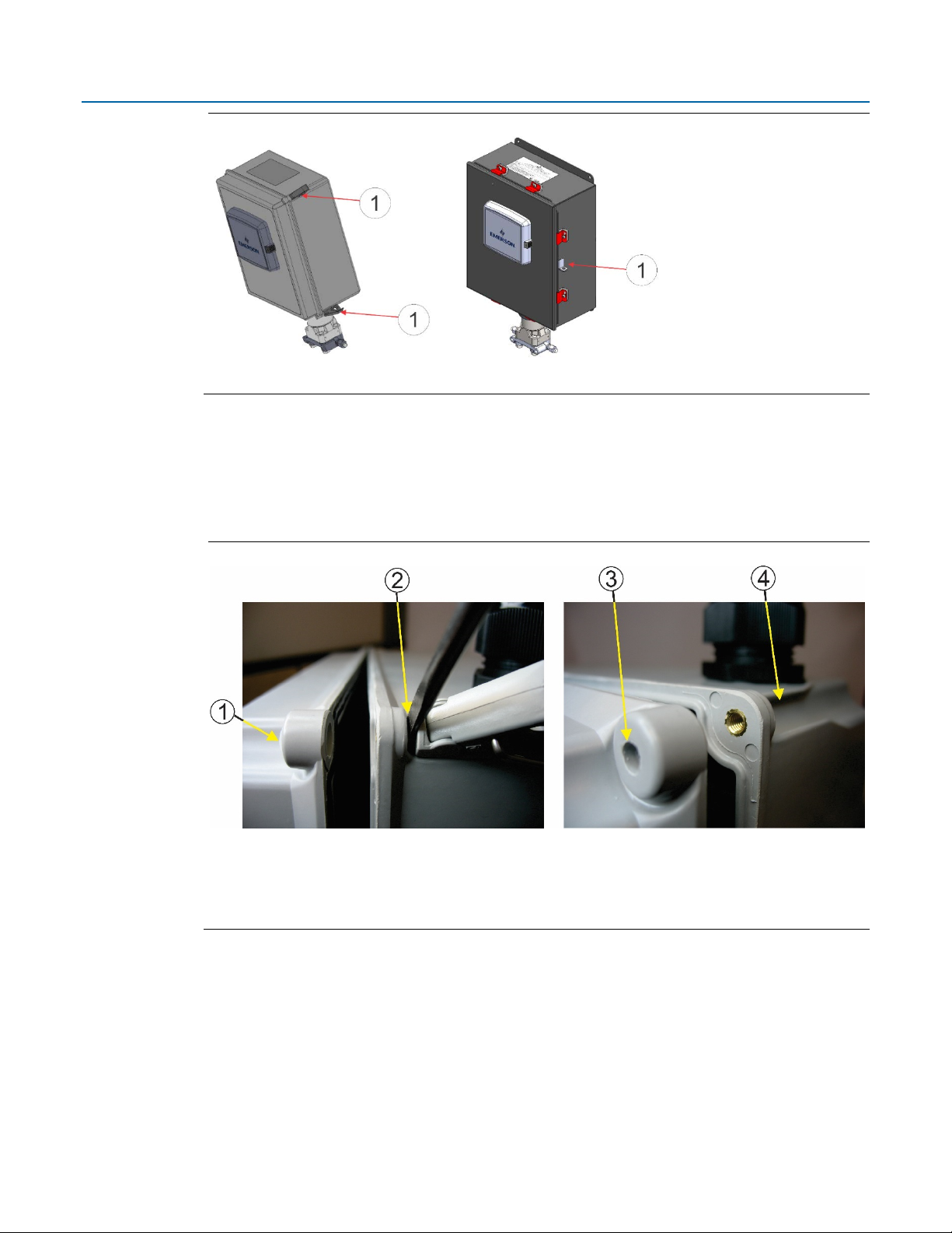
1.12 Physical Security
The flow computer enclosure enables you padlock the door shut. The fiberglass enclosure supports
two padlocks (left in Figure 1-6); the aluminum enclosure supports one padlock (right in Figure 1-6).
Introduction 9
Page 14
Emerson FB2200 Flow Computer Instruction Manual
1
Location where customer-supplied padlocks can be used to lock the door
1
Cap
2
Prying off the latch
3
Cap removed
4
Latch removed
D301784X012
November 2020
Figure 1-6. Possible Padlock Locations
Holes in the door latches of the fiberglass enclosure allow you to attach a wire seal.
Alternatively, you can use a pan head screw (#10-32 X 0.81 316 SS or Monel alloy 400) with an Oring (0.15 ID, 0.07 W) in place of one or both door latches to screw the door shut. In this case, you
pry off the latch with a flat head screwdriver and pop out the mating cap to free up the holes for the
screw.
Figure 1-7. Removing Cap and Latch from Fiberglass Enclosure
For ATEX/IEC-compliant installations with the fiberglass enclosure, you must use one of these three
choices (padlock, wire seal, or screw).
For either enclosure type, you may apply tamper-evident tape to the four sensor coupling screws
and two rotation set screws to provide evidence of unauthorized sensor adjustments. The four
coupling screws also include holes through which you could attach a wire seal.
10 Introduction
Page 15

Figure 1-8. Potential Locations for Tamper-evident Tape
1
Rotation Set Screws (2) – One shown
2
Coupling Screws (4) – Two shown
Emerson FB2200 Flow Computer Instruction Manual
D301784X012
November 2020
Introduction 11
Page 16

Emerson FB2200 Flow Computer Instruction Manual
D301784X012
November 2020
12 Introduction
Page 17

Section 2: Installation
This section covers the following topics:
Hazardous Locations
Emerson FB2200 Flow Computer Instruction Manual
D301784X012
November 2020
Environmental Specifications
Required Tools
Site Considerations
General Wiring Guidelines
Grounding
Opening/Closing the Enclosure
Mounting the Enclosure
Power Modes
Connecting Power
Installing the Optional 30W Solar Panel
Adjusting the Optional Solar Panel
Connecting Communications Ports
Door Contact Terminal
The flow computer ships from the factory fully assembled, except for the optional solar panel
assembly.
2.1 Hazardous Locations
For North America the FB2200 has certifications for Class I Division 2 (Groups A, B, C, & D) nonincendive, and non-hazardous locations only. Appendix A contains special information for Class I
Division 2 installations.
For other world areas the FB2200 has ATEX and IEC Ex certifications for Ex nA Zone 2 non-sparking
installations and non-hazardous locations only. See Appendix B for more information.
All certifications are listed on the data plate located on the top of the device.
2.2 Environmental Specifications
This section summarizes the environmental specifications for the device. For full details, refer to
the product data sheet FB2200 Flow Computer (D301792X012).
Installation 13
Page 18

Emerson FB2200 Flow Computer Instruction Manual
Specification
Configuration
Range
Aluminum Enclosure
Fiberglass Enclosure
Ambient
No battery, C1D2
–40 °C to +80 °C
–
35 °C to 80 °C
No Battery, C1D2,
–40 °C to 60 °C
–35 °C to 60 °C
Lead Acid Battery,
–40 °C to 45 °C
–35 °C to 45 °C
ATEX/IEC Ex nA
–25 °C to 55 °C
–25 °C to 55 °C
Humidity
5% to 95% non-condensing
Vibration
2g over 10 to 150 Hz; 1g over 150 to 200 Hz
Tool
Use
Torque wrench
For bolting/mounting the flow computer
2.5 mm hexagonal wrench
For manipulating rotation set screw
#1 Phillips-head screwdriver
For screws on HMI module
#2 Phillips-head screwdriver
For screws on other modules and boards
#3 Phillips-head screwdriver
For optional aluminum enclosure clamps
1/8 inch flat-head screwdriver
For 5.08 mm pitch terminal block connections
7/32 inch flat-head screwdriver
For installing external solar controller
Utility knife
For installing external solar controller
Wire cutters
For installing external solar controller
Wire strippers
For installing external solar controller
Laptop PC running Field Tools with FBxConnect
D301784X012
November 2020
Table 2-1. Environmental Specifications
Temperature
Relay installed
C1D2
No Battery
2.3 Required Tools
Certain tools and equipment are required for installing and servicing the flow computer.
Table 2-2. Required Tools
(-40 °F to +176 °F)
(–40 °F to 140 °F)
(–40 °F to 113 °F)
(–13 °F to 131 °F)
(–31 °F to 176 °F)
(–31 °F to 140 °F)
(–31 °F to 113 °F)
(–13 °F to 131 °F)
14 Installation
configuration software
For configuring
Page 19
Emerson FB2200 Flow Computer Instruction Manual
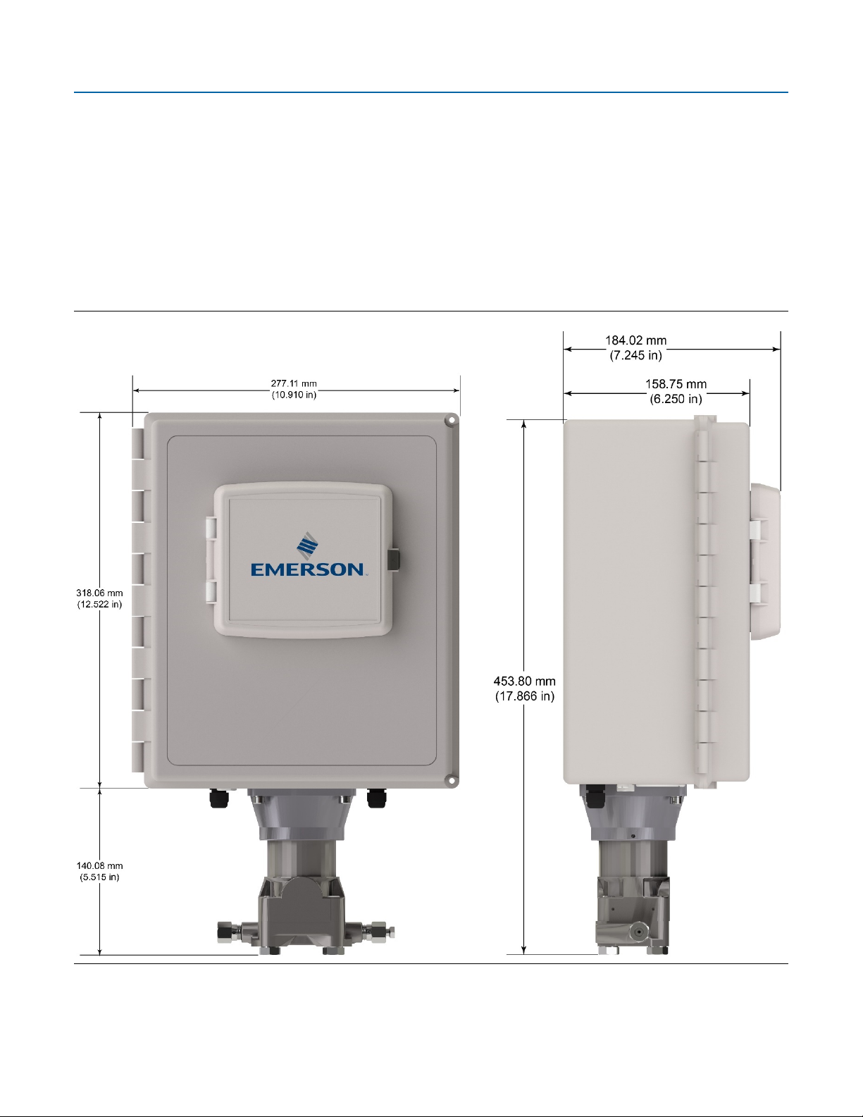
2.4 Site Considerations
The flow computer must reside in an accessible location for configuration and service. Refer to the
dimensional drawings for information on the space required.
Ensure the installation location provides easy access to the HMI module.
If your unit includes the optional solar panel, ensure the installation location provides
sufficient space to mount the solar panel and adequate sunlight to charge the battery.
If your unit includes the optional FBxWifi ensure the installation location provides line-ofsight access to the transceiver.
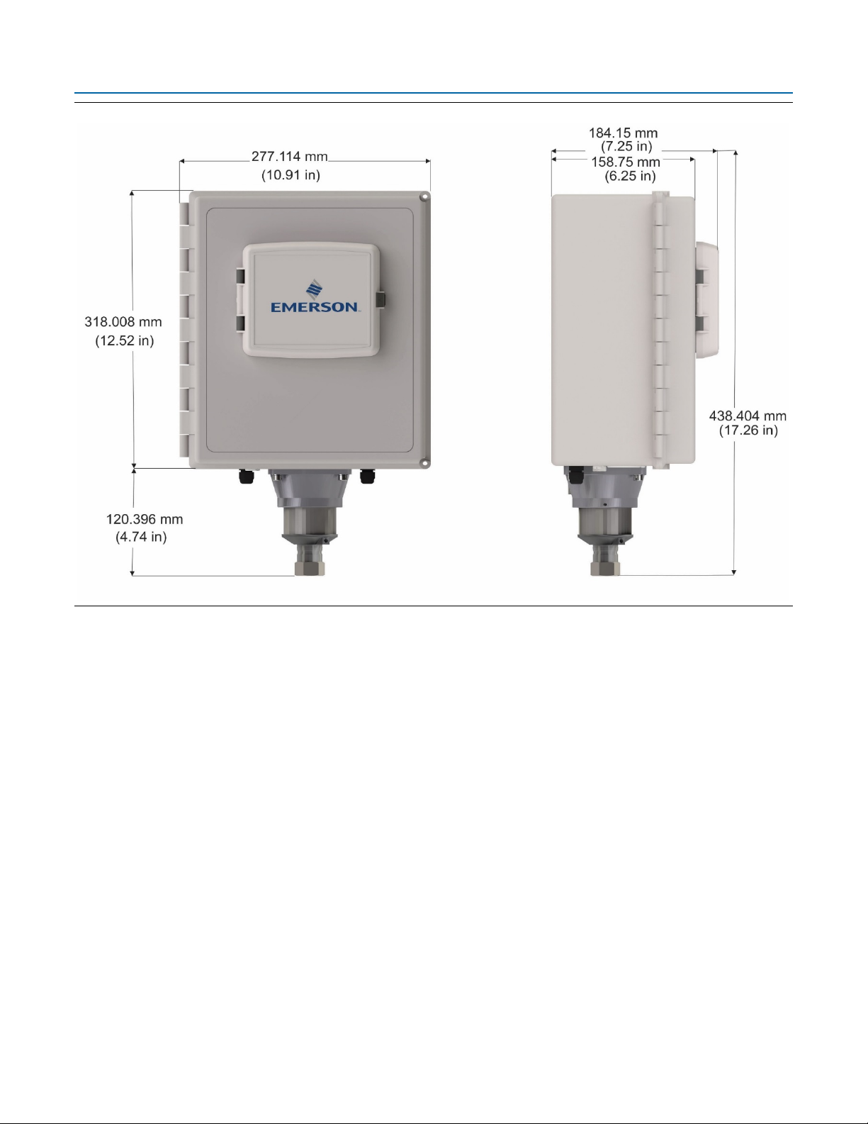
Figure 2-1. Dimensions – Multivariable Sensor Version - Fiberglass Enclosure
D301784X012
November 2020
Installation 15
Page 20
Emerson FB2200 Flow Computer Instruction Manual
D301784X012
November 2020
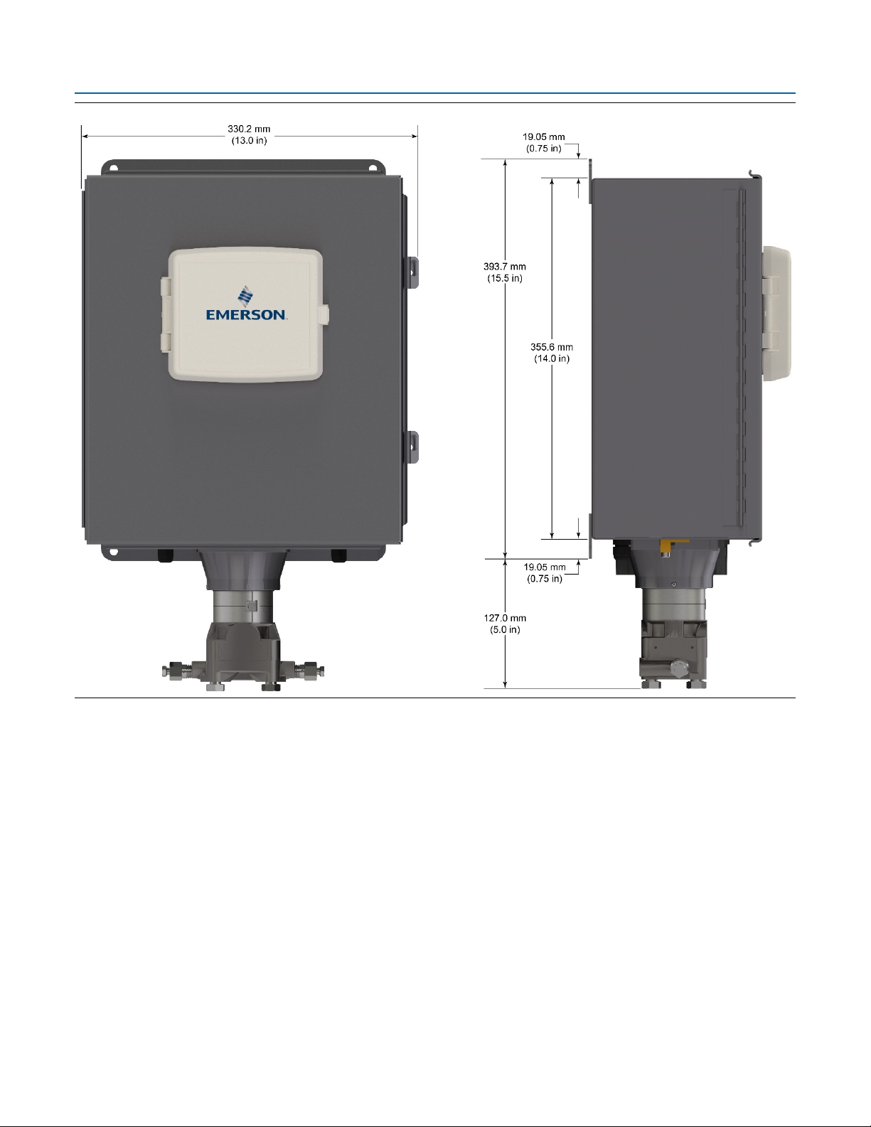
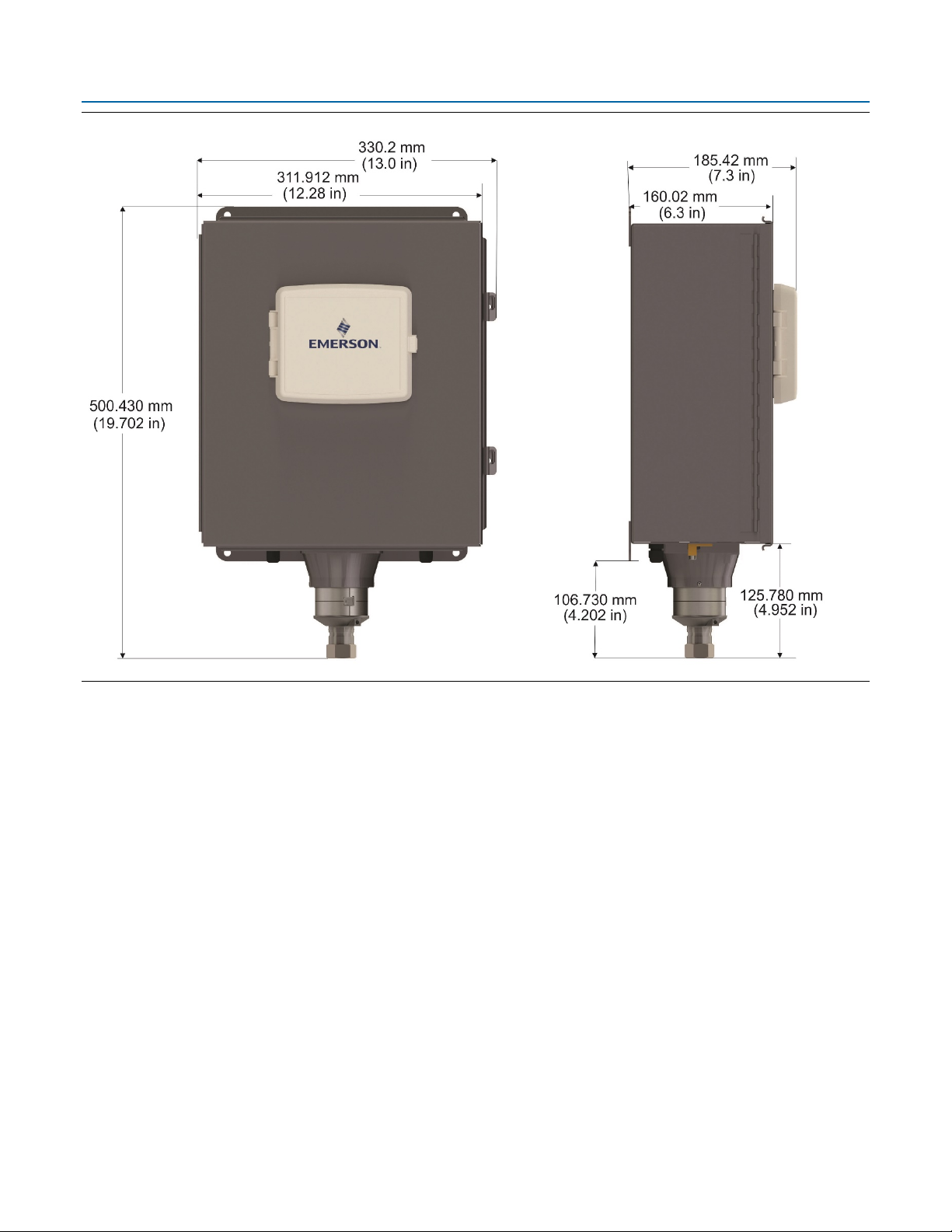
Figure 2-2. Dimensions – Multivariable Sensor Version - Aluminum Enclosure
16 Installation
Page 21

Emerson FB2200 Flow Computer Instruction Manual
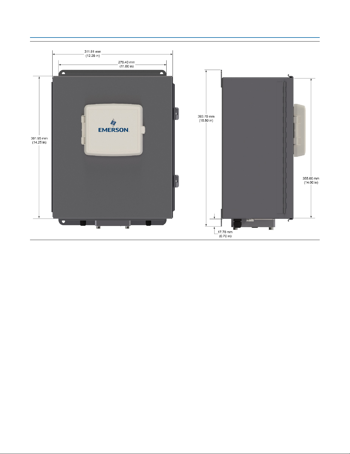
Figure 2-3. Dimensions – No Integral Sensor Version – Fiberglass Enclosure
D301784X012
November 2020
Installation 17
Page 22
Emerson FB2200 Flow Computer Instruction Manual
D301784X012
November 2020
Figure 2-4. Dimensions – No Integral Sensor Version – Aluminum Enclosure
18 Installation
Page 23
Emerson FB2200 Flow Computer Instruction Manual
Figure 2-5. Dimensions – Static Pressure Sensor Version – Fiberglass Enclosure
D301784X012
November 2020
Installation 19
Page 24
Emerson FB2200 Flow Computer Instruction Manual
D301784X012
November 2020
Figure 2-6. Dimensions – Static Pressure Sensor Version – Aluminum Enclosure
2.5 General Wiring Guidelines
The flow computer’s pluggable terminal blocks use compression-type terminals that
accommodate wire between 28 and 12 AWG.
When making a connection, insert the bare end of the wire (approx. 1/4" max) into the clamp
adjacent to the screw and secure the screw.
To prevent shorts, ensure that no bare wire is exposed.
Allow some slack in the wire while making terminal connections. Slack makes the wires more
manageable and helps minimize mechanical strain on the terminal blocks.
Use twisted pair, shielded and insulated cable for communication and I/O wiring to minimize
signal errors caused by electromagnetic interference (EMI), radio frequency interference
(RFI) and transients. When using shielded cable, ground all shields at only one point in the
appropriate system. This prevents circulating ground current loops that can cause signal
errors.
20 Installation
Page 25
2.6 Grounding
The flow computer includes a ground stud on the bottom of the battery compartment
Figure 2-7. Ground Stud
Once you have installed the unit, run a ground wire between the ground stud on the
bottom of the battery compartment and a known good earth ground. You route the
ground wire through one of the conduit fittings.
Use stranded copper wire to earth ground and keep the length as short as possible.
Clamp or braze the ground wire to the ground bed conductor (typically a stranded
copper AWG 0000 cable installed vertically or horizontally).
Run the ground wire so that any routing bend in the cable has a minimum radius of
30.48 cm (12 inches) below ground and 20.32 cm (8 inches) above ground.
For more information on grounding or if your installation uses cathodic protection, refer to Site
Considerations for Equipment Installation, Grounding, and Wiring (D301452X012).
Emerson FB2200 Flow Computer Instruction Manual
D301784X012
November 2020
2.7 Opening/Closing the Enclosure
The enclosure opens/closes differently depending upon whether you have the fiberglass enclosure
or the aluminum enclosure.
DANGER
EXPLOSION HAZARD: Never open the enclosure in a hazardous location. Opening the enclosure in
a hazardous location could result in an explosion.
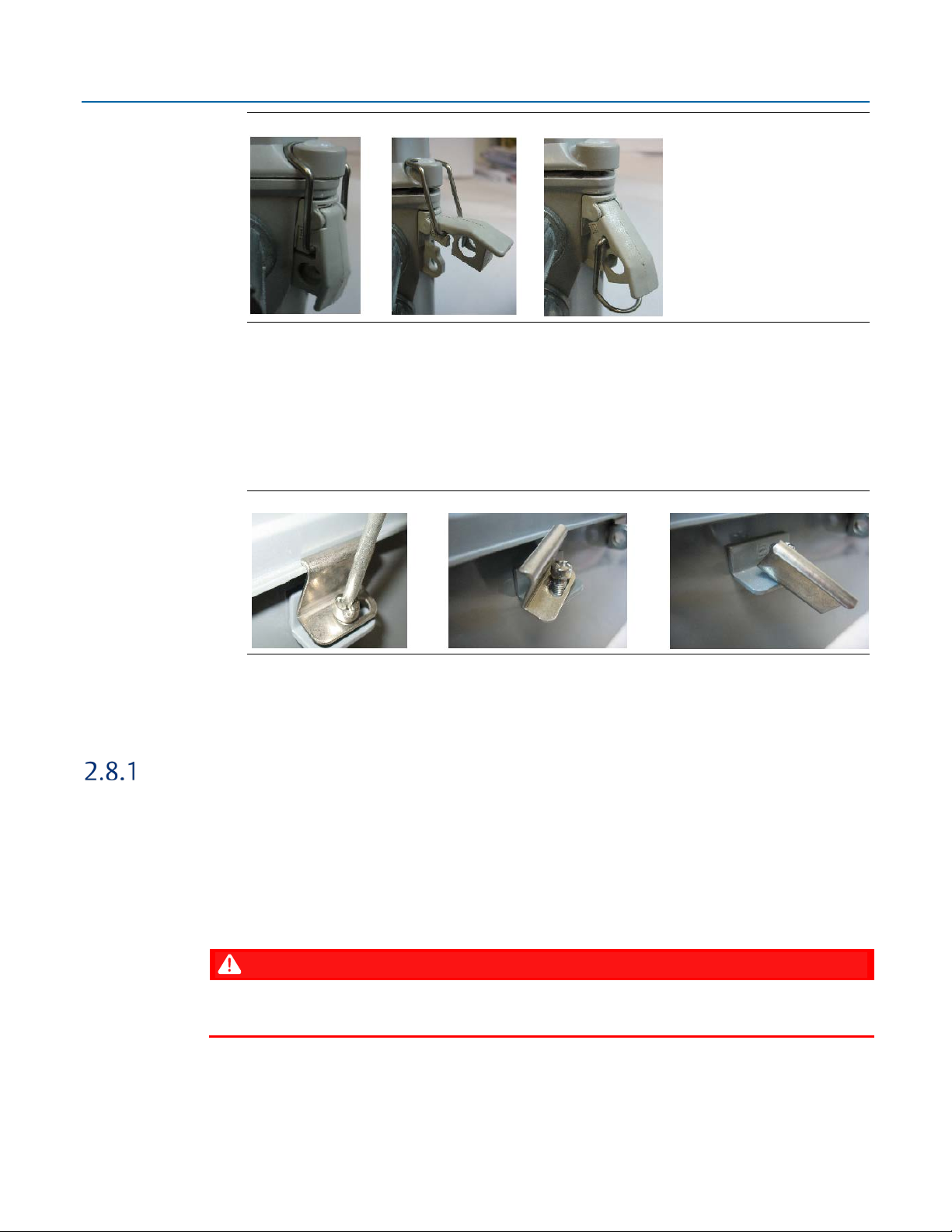
Fiberglass Enclosure
The enclosure includes two fasteners at the top and bottom of the door. To open the door,
lift the clasp to loosen the latch and pull it free of the post, then repeat for the other fastener
and open the door. To fasten the door, place the latch on the post and press down the clasp;
repeat for the other fastener.
Installation 21
Page 26
Emerson FB2200 Flow Computer Instruction Manual
D301784X012
November 2020
Figure 2-8. Fiberglass Enclosure Fasteners
Aluminum Enclosure
The enclosure includes six clamps along the edge of the door (two at the top, two on the
bottom, two at the side). To open the door, use a Phillips-head screwdriver to loosen (but not
remove) the screws enough so you can then pop the clamp free of the lip of the door, then
repeat for the other clamps and open the door. To fasten the door, place the clamp over the
door lip then tighten the screw torqueing to 20 in-lbs (2.3 N m); repeat for the other clamps.
Figure 2-9. Aluminum Enclosure Clamps
2.8 Mounting the Enclosure
You can mount the flow computer directly to a pole. You can also mount it on a wall or panel.
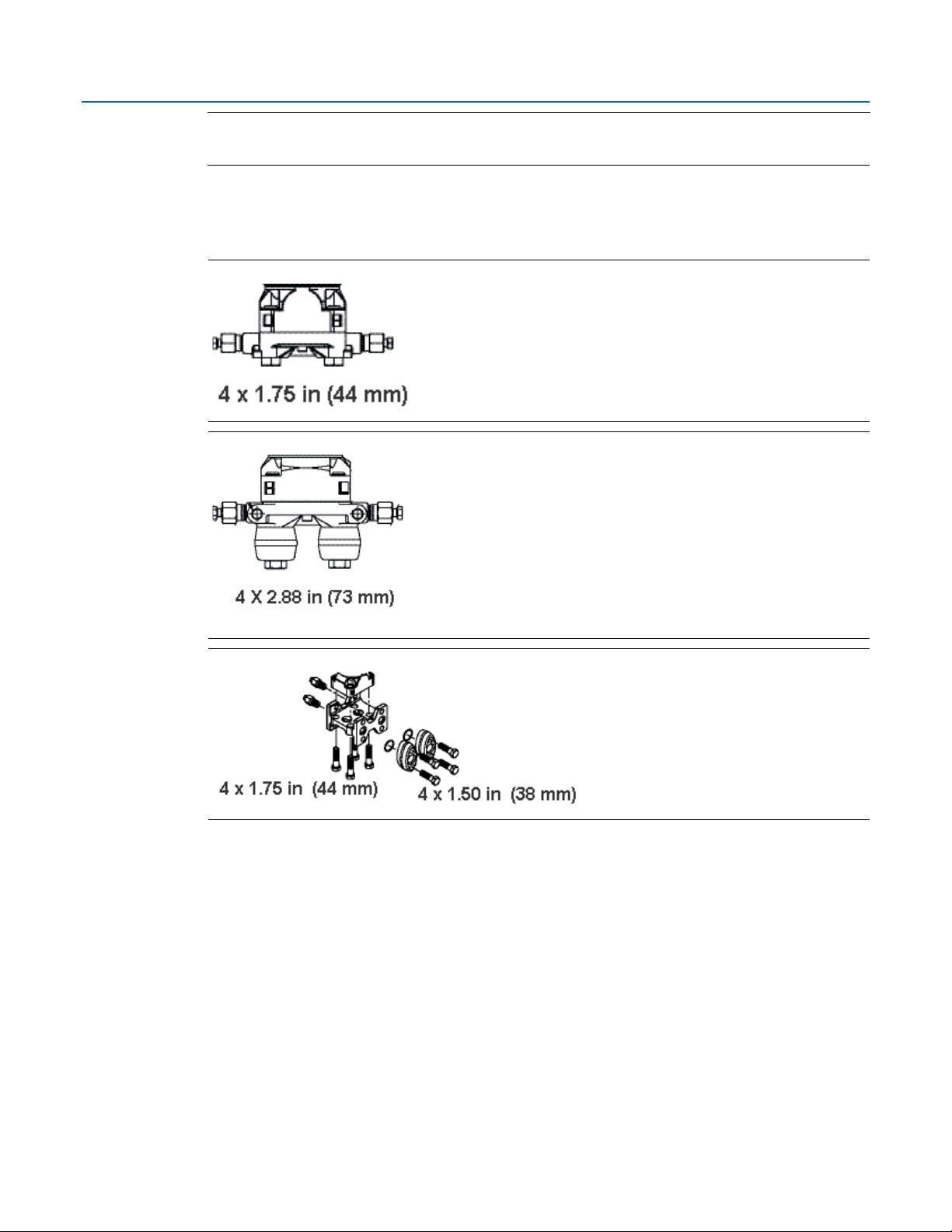
Bolting Considerations
If the flow computer installation requires assembly of a process flange, manifold, or flange
adapters, follow these assembly guidelines to ensure a tight seal for optimal performance
characteristics of the flow computer.
Only use bolts supplied with the flow computer or sold by Emerson Remote Automation Solutions
as spare parts. Refer to the figure for common flow computer assemblies with the bolt length
required for proper flow computer installation.
DANGER
EXPLOSION HAZARD: Ensure the area in which you perform this operation is non-hazardous.
Performing this operation in a hazardous area could result in an explosion.
22 Installation
Page 27
Emerson FB2200 Flow Computer Instruction Manual
D301784X012
November 2020
Note
For all other manifolds, contact your local Emerson Sales office or Emerson Impact Partner.
Bolts are typically carbon steel or stainless steel. Confirm the material by viewing the markings on
the head of the bolt and referencing the figure. If bolt material is not shown in the figure, contact
your local Emerson Remote Automation Solutions representative for more information.
Figure 2-10. Transmitter with Coplanar Flange
Figure 2-11. Transmitter with Coplanar Flange and Optional Flange Adapters
Figure 2-12. Transmitter with Traditional Flange and Optional Flange Adapters
Installation 23
Page 28
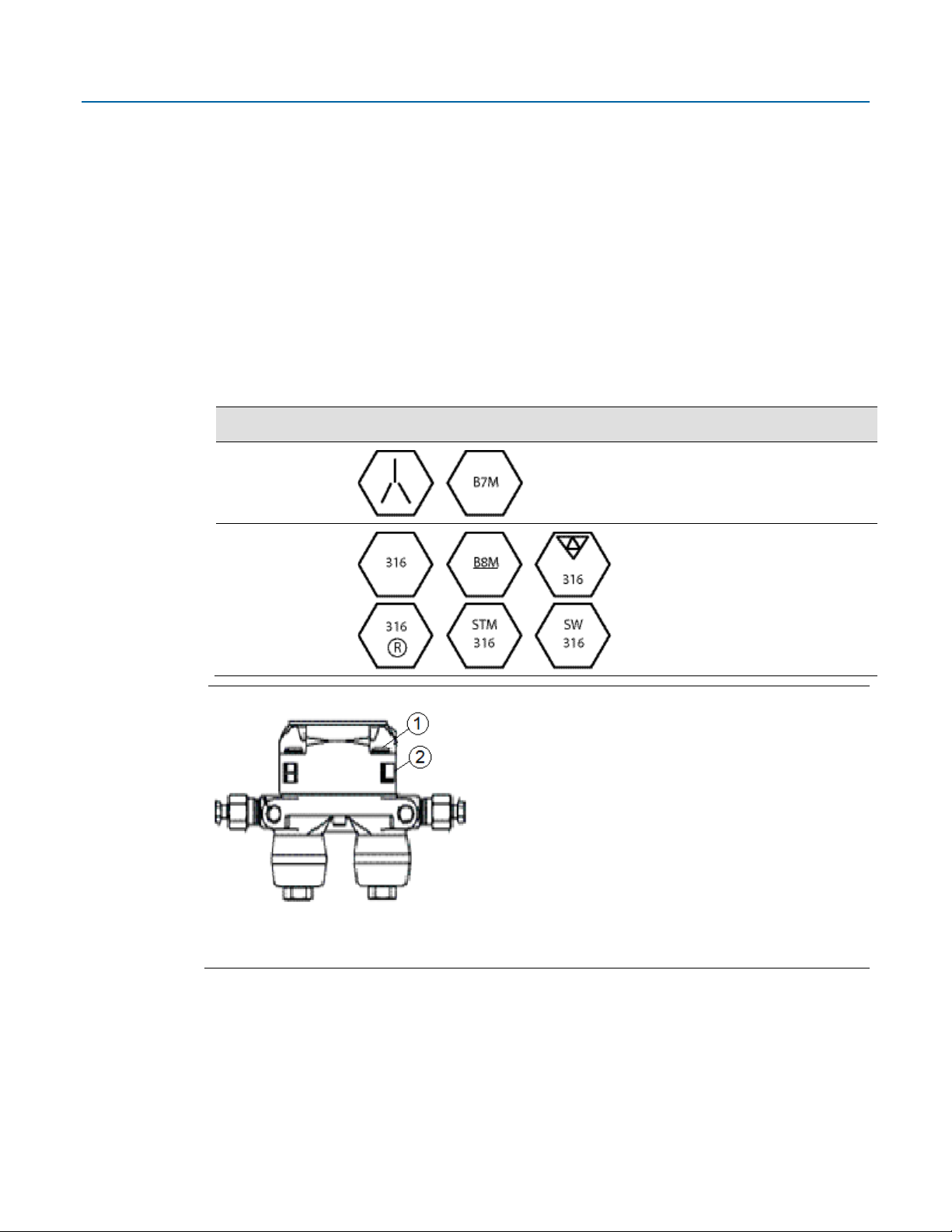
Emerson FB2200 Flow Computer Instruction Manual
Bolt Material
Head markings
Initial Torque
Final Torque
1
Bolt
2
Sensor module
D301784X012
November 2020
Use the following bolt installation procedure:
Carbon steel bolts do not require lubrication. Stainless steel bolts are factory-coated with a
1.
lubricant to ease installation. Do not apply any additional lubricant when installing either
type of bolt.
Finger-tighten the bolts.
2.
Torque the bolts to the initial torque value using a crossing pattern. See Table 2-3 for initial
3.
torque value.
Torque the bolts to the final torque value using the same crossing pattern. See Table 2-3 for
4.
final torque value.
Verify that the flange bolts protrude through the sensor module before applying pressure.
5.
T
able 2-3. Torque Values for the Flange and Flange Adapter Bolts
Carbon Steel (CS)
Stainless Steel
(SST)
Figure 2-13. Proper Bolt Installation
300 in. -lbs.
(33.9 N m)
150 in. -lbs.
(16.9 N m)
650 in. -lbs.
(73.4 N m)
300 in. -lbs.
(33.9 N m
24 Installation
Page 29
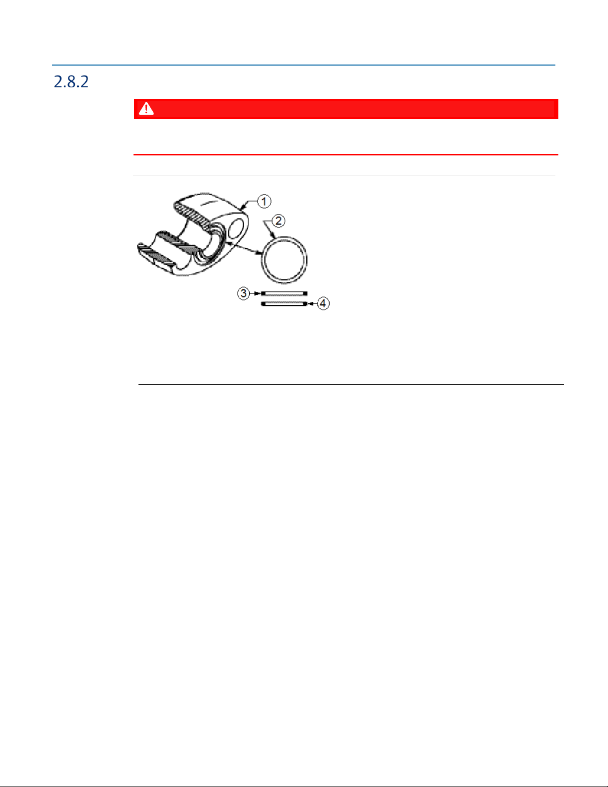
O-rings with Flange Adapters
1
Flange
2
O-ring
3
Square PTFE-based profile
4
Round Elastomer profile
Emerson FB2200 Flow Computer Instruction Manual
D301784X012
November 2020
DANGER
Failure to install proper flange adapter O-rings may cause process leaks, which can result in death
or serious injury. Only use the O-ring that is designed for its specific flange adapter.
Figure 2-14. O-rings with Flange Adapters
Whenever the flange or adapters are removed, visually inspect the O-rings.
1.
Replace the O-rings if there are any signs of damage, such as nicks or cuts.
2.
If the O-rings are replaced, re-torque the flange bolts and alignment screws after installation
3.
to compensate for seating of the O-rings.
Installation 25
Page 30
Emerson FB2200 Flow Computer Instruction Manual
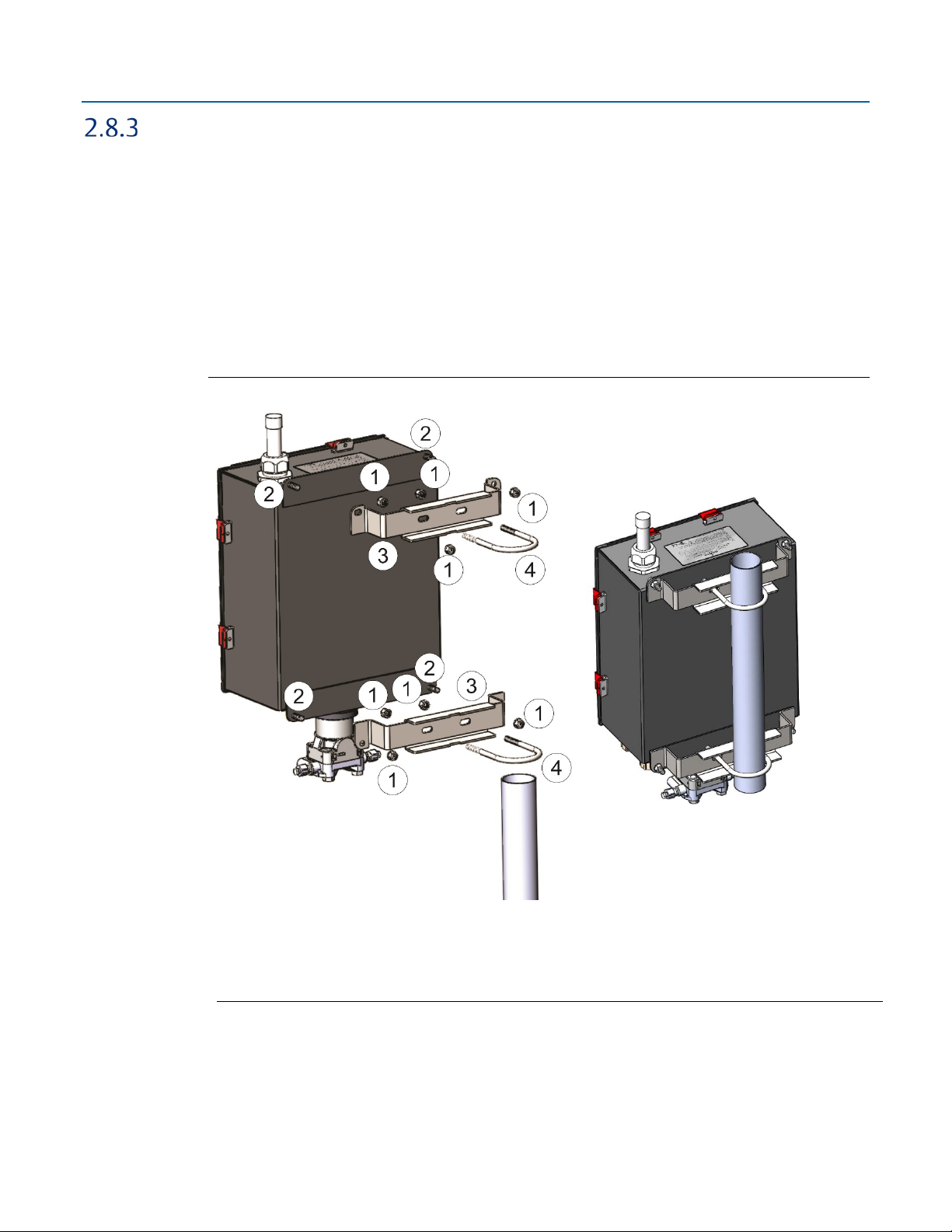
1
5/16-18 keps stainless steel hex nut
2
5/16-18 x 1.0 LG wire-lockable socket head cap screw
3
Pole mounting bracket
4
2-inch diameter 5/16-18 x 4.0LG U-bolt
D301784X012
November 2020
Pole Mounting – Aluminum Enclosure
Refer to Figure 2-15 during the mounting procedure.
Apply Loctite
1.
screws (Item 2).
Attach pole mounting brackets (Item3) to enclosure using head cap screws (Item 2) and hex
2.
nuts (Item 1). Torque hex nuts to 30 in-lbs (3.4 N m).
Apply Loctite 222 Threadlocker sparingly to threads of U-bolts (Item 4).
3.
Use U-bolts (Item 4) to mount enclosure to pole using hex nuts (Item 1). Torque hex nuts to
4.
30 in-lbs (3.4 N m).
Figure 2-15. Aluminum Enclosure Pole Mounting
®
222 Low Strength Purple Threadlocker sparingly to threads of head cap
26 Installation
Page 31

Emerson FB2200 Flow Computer Instruction Manual
1
¼ inch screw split lock stainless steel washer
2
¼-10 x .75LG thread forming torx head screw
3
5/16-18 keps stainless steel hex nut
4
Pole mounting bracket
5
2 inch diameter 5/16-18 x 4.0LG U-bolt
Pole Mounting – Fiberglass Enclosure
Refer to Figure 2-16 during the mounting procedure.
Attach plastic pole mounting brackets (Item4) to enclosure using split lock stainless steel
1.
washers (Item 1) and torx head screws (Item 2).
Apply Loctite 222 Low Strength Purple Threadlocker adhesive sparingly to threads of U-bolts
2.
(Item 5).
Use U-bolts (Item 5) to mount enclosure to pole using hex nuts (Item 3). Torque hex nuts to
3.
30 in-lbs (3.4 N m).
Figure 2-16. Fiberglass Enclosure Pole Mounting
D301784X012
November 2020
Installation 27
Page 32

Emerson FB2200 Flow Computer Instruction Manual
A
Mounting holes are 7.92 mm (0.312 in) diameter
D301784X012
November 2020
Panel/Wall Mounting Dimensions – Aluminum Enclosure
Figure 2-17. Aluminum Enclosure Panel/Wall Mounting
28 Installation
Page 33

Emerson FB2200 Flow Computer Instruction Manual
D301784X012
November 2020
Panel/Wall Mounting Dimensions – Fiberglass Enclosure
Prior to mounting, attach mounting tabs to enclosure:
Figure 2-18. Attaching mounting tabs
Installation 29
Page 34

Emerson FB2200 Flow Computer Instruction Manual
A
Mounting holes are 7.9 mm (0.31 in) wide
D301784X012
November 2020
Figure 2-19. Fiberglass Enclosure Panel/Wall Mounting
30 Installation
Page 35

Rotating the Housing
1
To improve accessibility to the HMI module or to ease wiring, you can optionally rotate the
housing.
Important
Never rotate the housing more than 180 degrees from its original (as-shipped) position. Overrotation can break electronics within the unit.
Figure 2-20. Housing Rotation Set Screw (1 each side)
Emerson FB2200 Flow Computer Instruction Manual
D301784X012
November 2020
Set Screw (one each side)
DANGER
EXPLOSION HAZARD: Ensure the area in which you perform this operation is non-hazardous.
Performing this operation in a hazardous area could result in an explosion.
1. Loosen the two housing rotation set screws.
2. Rotate the housing no more than 180 degrees from its original (as-shipped) position.
3. Re-tighten the two housing rotation set screws. Torque to 6 in-lbs. (0.7 N m).
Installation 31
Page 36

Emerson FB2200 Flow Computer Instruction Manual
Description
Power Usage
(mW) at 12Vdc
Base flow computer with integral multivariable DP and pressure sensor and
Base flow computer with integral multivariable DP and pressure sensor and
Additional Load Options:
Display and backlight active
340
FBxWifi active
379
FBxWifi and display active
398
DO active (1 Hz, 50:50 duty cycle, no load)
12
PI active (10 KHz, 50:50 duty cycle, square wave)
12
D301784X012
November 2020
2.9 Power Modes
To keep power consumption to a minimum, especially for remote sites, the FB2200 can run in two
different power modes – Low Power Mode (4 MHz or 8 CPU MHz clock speed) or Standard Power
Mode (60 MHz CPU clock speed).
Low Power Mode
The FB2200 normally runs in low power mode for typical metering applications. The radio Power
Control function (configurable in FBxConnect) switches the flow computer into standard power
mode at specific times when serial communications are required, then it reverts to low power
mode when the communication period is over. A serial connection to a remote 4088B MVT can
occur in low power mode.
The local display (HMI module) with FBxWifi uses additional power. You can configure it in
FBxConnect to shut down after a period of inactivity.
Important
You must disable the Ethernet port (using a jumper) to run in low power mode. See Section 2.13.3.
Table 2-4. Typical Power Usage – Low Power Mode at Room Temperature
temperature measurement, single DO available, for a single meter run
Historical configuration supports maximum of:
4 averages
12 Station 1 history points (Group 4)
10 User Periodic history points (Group 1)
temperature measurement, 2 digital and 2 analog channels available for a
single meter run
Historical configuration supports maximum of:
4 averages
12 Station 1 history points (Group 4)
10 User Periodic history points (Group 1)
55
67
32 Installation
Page 37

Important
Description
Power Usage
(mW) at 12Vdc
Power Usage
(mW) at 24Vdc
Base flow computer with integral multivariable DP and
Base flow computer with temperature measurement (no
Base flow computer with integral multivariable DP and
Base flow computer with temperature measurement, integral
Base flow computer with integral multivariable DP and
If you increase the number of history points/averages beyond any of the maximum limits in Table 2-
4, the flow computer
mode.
cannot operate in low power mode and automatically runs in standard power
Standard Power Mode
When serial communication is active (other than to a remote 4088B MVT) the FB2200 operates in
standard power mode. The unit also uses standard power mode when:
The HMI module display is ON
FBxWifi is active
Ethernet port is enabled in the flow computer
Modbus Master communication is active
PID, Math/logic Blocks, Action Blocks, and Effect Blocks are enabled
Power control zone is enabled
Emerson FB2200 Flow Computer Instruction Manual
D301784X012
November 2020
Table 2-5. Typical Power Usage – Standard Power Mode at room temperature
pressure sensor and temperature measurement for a single
meter run
integral sensor) communicating to remote 4088B (externally
powered) for a single meter run
pressure sensor and temperature measurement, 2 digital and
2 analog channels available for a single meter run
static pressure sensor and pulsed input for a single meter run
pressure sensor and temperature measurement,
communicating to remote 4088B (externally powered) for a
dual meter run
240 290
220 268
260 313
276 330
250 300
Installation 33
Page 38

Emerson FB2200 Flow Computer Instruction Manual
Description
Power Usage
(mW) at 12Vdc
Power Usage
(mW) at 24Vdc
Additional Load Options:
Display and backlight active
159
188
FBxWifi active
191
199
FBxWifi and display active
233
245
DO active (1 Hz, 50:50 duty cycle, no load)
20
23
PI active (10 KHz, 50:50 duty cycle, square wave)
14
15
8-channel expansion I/O module installed (isolated)
228
280
Additional 6-channel expansion I/O module installed
68
66
Ethernet enabled 100 Mbit
430
466
Ethernet active 100 Mbit
640
650
Loop power supply
310
393
D301784X012
November 2020
Table 2-5. (Continued)
(isolated)
Notes on Battery Life
Battery life varies based on numerous factors including temperature, communication usage, and
various load options. To achieve the maximum battery life noted in the product data sheet requires
that you:
Limit use of the display, backlight, and FBxWifi options.
Limit communication activity.
Disable power to all I/O (except for the MV or static pressure sensor, or RTD). To do this, click
Configure > I/O Setup > I/O Configuration > Properties and select Disable for each I/O
module.
Figure 2-21. Module Power Control
34 Installation
Page 39

2.10 Connecting Power
1
To external DC power supply
Power can come from an external DC supply or a lead acid battery pack with a solar panel.
Connecting DC Power
Emerson FB2200 Flow Computer Instruction Manual
D301784X012
November 2020
DANGER
EXPLOSION HAZARD: Ensure the area in which you perform this operation is non-hazardous.
Performing this operation in a hazardous area could result in an explosion.
When power comes from an external DC supply, connect using the +DCIN and –DCIN terminals.
Use standard copper wire (#18 AWG minimum). The device supports both 12V and 24V power
supplies. It accepts DC voltage from 10.5 to 30V; the amount of power required varies depending
upon the options used.
Important
If your installation uses DC power for main power, do not wire battery power as a secondary (back
up) power source. Certification only allows a
void your certification.
Figure 2-22. DC Power Connections
single
main power source; wiring both sources will
Installation 35
Page 40

Emerson FB2200 Flow Computer Instruction Manual
D301784X012
November 2020
Connecting Battery Power
DANGER
EXPLOSION HAZARD: Ensure the area in which you perform this operation is non-hazardous
Performing this operation in a hazardous area could result in an explosion.
When power comes from an internal battery pack, the battery pack plugs into one of two pairs of
connectors.
2.10.2.1 Installing the Main Battery Pack
If you purchased one of the battery/solar panel options, you need to install the main battery pack
before you place the device in service.
The device provides a battery cable with two pairs of battery connectors, enabling you to hot-swap
the battery pack in a non-hazardous location. You can use either pair of connectors when you
install the battery.
Remove the battery pack from its packaging.
1.
2.
Remove the plastic tabs covering the connectors on the battery pack.
Figure 2-23. Removing Plastic Tabs from Battery Pack
Open the enclosure.
3.
36 Installation
Page 41

Emerson FB2200 Flow Computer Instruction Manual
1
Captive Fastening Screws
D301784X012
November 2020
Loosen the two captive fastening screws at the top of the of the battery compartment, while
4.
holding onto the battery compartment door. Carefully rotate the electronics assembly
towards you to reveal the inside of the battery compartment. A strap prevents the front of
the compartment from rotating too far forward.
Figure 2-24. Captive Fastening Screws
Installation 37
Page 42

Emerson FB2200 Flow Computer Instruction Manual
D301784X012
November 2020
Figure 2-25. Rotate Assembly Forward
The battery cable inside the battery compartment is divided into two branches, each with its
5.
own pair of connectors. Take either pair of connectors and connect them to the battery; the
red (positive) wire connector attaches to the red connection point on the battery and the
black (negative) wire connector attaches to the black connection point on the battery.
38 Installation
Page 43

Figure 2-26. Connect the Battery
Emerson FB2200 Flow Computer Instruction Manual
D301784X012
November 2020
Now you must secure the battery in the battery compartment so that it doesn’t move
6.
around. How you do this depends on which battery compartment configuration you have. If
the battery compartment includes a strap for holding the battery, see Section 2.10.2.1 –
Securing the Battery with a Strap; if the battery compartment includes an adhesive pad, see
Section 2.10.2.2 – Securing the Battery to the Pad.
Installation 39
Page 44

Emerson FB2200 Flow Computer Instruction Manual
D301784X012
November 2020
2.10.2.2 Securing the Battery with a Strap
This type of battery compartment allows for certain accessories to be installed such as a relay or
internal solar regulator.
1. If you have an internal solar regulator installed in the battery compartment, you must
remove its termination cover in order to fit the battery inside. Remove the two screws (left
and right) that fasten the termination cover to the solar regulator, and then set the
termination cover aside. (If you don’t have an internal solar regulator, skip to Step 2.)
Figure 2-27. Removing Termination Cover of Internal Solar Regulator
2. The battery strap must already be threaded through the holes of the battery compartment.
Figure 2-28. Battery Strap
3. Pick up the battery and carefully ease it into the battery compartment with the writing on
the battery facing out and the connectors on the upper right-hand side. Nothing (including
the strap) can be
40 Installation
behind the battery.
Page 45

Emerson FB2200 Flow Computer Instruction Manual
Figure 2-29. Easing Battery Pack into Compartment
D301784X012
November 2020
4. Carefully push the battery under the solar regulator (if present) and against the back of the
compartment, now strap it in tightly by pulling the ends of the strap.
Figure 2-30. Battery Pack Attached to Compartment
5. The strap includes a narrow opening into which you can slide the other end of the strap to
help you tighten it.
Installation 41
Page 46

Emerson FB2200 Flow Computer Instruction Manual
D301784X012
November 2020
Figure 2-31. Battery Pack Attached to Compartment
6. Route the extra portion of the strap as well as the wires of the free portion of the battery
cable so that they sit in an open area of the battery compartment.
7. If you had to remove the termination cover of an internal solar regulator (Step 1), re-attach
the termination cover.
8. Rotate the electronics assembly up against the battery compartment and tighten the captive
fastening screws with a torque value of 2 to 4 in-lbs. (0.2 to 0.5 N m) to close the
compartment.
2.10.2.3 Securing the Battery to the Pad
For this type of battery compartment, a hook-and-loop adhesive pad on the back of the battery
secures it to the back of the battery compartment.
Pick up the battery and align it with the lower left edge of the battery compartment. Press it
1.
against the back of the compartment so the pad on the back of the battery secures to the
back of the battery compartment.
42 Installation
Page 47

Emerson FB2200 Flow Computer Instruction Manual
Figure 2-32. Battery Pack Attached to Compartment
D301784X012
November 2020
Route the wires of the free portion of the battery cable so that they sit completely inside the
2.
open area at the top of the battery compartment.
Rotate the electronics assembly up against the battery compartment and tighten the captive
3.
fastening screws with a torque value of 2 to 4 in-lbs (0.2 to 0.5 N m) to close the
compartment.
Close the enclosure.
4.
Installation 43
Page 48

Emerson FB2200 Flow Computer Instruction Manual
D301784X012
November 2020
Connecting Solar Power
DANGER
EXPLOSION HAZARD: Ensure the area in which you perform this operation is non-hazardous.
Performing this operation in a hazardous area could result in an explosion.
Restriction
The solar panel and lead acid battery combination cannot be used with ATEX/IECEx applications.
When power comes from a solar panel/lead acid battery combination, connect using the BATT+
and BATT– terminals and standard copper wire (#18 AWG minimum).
Important
Only use batteries supplied with the flow computer or sold by Emerson as spare parts for this
flow computer. If you substitute a battery you obtain elsewhere
unless it is the identical part from the same manufacturer as that supplied with the flow
computer from Emerson.
If you purchase a solar panel/external solar regulator combination other than the Emerson-
approved option, it
must meet the specifications listed in Tables 2-6 and 2-7.
2.10.3.1 Wiring the 30W Solar Panel
For the 30W solar panel option with an external solar controller (charger/regulator) purchased
through Emerson (Emerson-approved option) connect the external solar controller to the flow
computer battery using the instructions in this section.
you will void your certification
If you are using your own external solar controller/30W solar panel not purchased through
Emersion, you can use this section as an example of a typical installation. You should also consult
the manufacturer’s instructions for your solar panel/solar regulator.
In either situation, you must use the battery, cables, and fuses supplied by Emerson for your
connections to the solar controller/solar panel.
Note
When making connections to the junction box or the solar regulator, you will need a suitable cable
gland/grommet to prevent water ingress to the junction box.
See Figure 2-39 for wiring instructions if you ordered the internal solar regulator.
44 Installation
Page 49

Emerson FB2200 Flow Computer Instruction Manual
Characteristic
Value/Range
Peak Power
30W ± 10%
Voltage (@peak power)
17.9V
Current (@peak power)
1.68A
Open Circuit Voltage
22.1V
Short Circuit Current
1.74A
Characteristic
Value/Range
Rated Solar Input
6A
Nominal System Voltage
12V
Maximum Solar Voltage
30V
3 stage charging
Bulk, PWM, and float
13.7V
Temperature Compensation
30 mV / °C
Operating Temperature
40 °C to 70 °C
Humidity
100%
Short Circuit Current
reverse polarity
Table 2-6. Solar Panel Electrical Characteristics
Table 2-7. Solar Regulator Electrical Characteristics
D301784X012
November 2020
Regulation Voltage
14.1V
Float Voltage
lightning and transient surges
short circuit
high temperature
overcurrent
reverse current at night
1. The solar controller comes with plastic mounting feet used only for surface mounting
applications. Remove the mounting feet but save the lock nut.
2. The solar controller also comes with fork connectors.
Installation 45
Page 50

Emerson FB2200 Flow Computer Instruction Manual
1
Solar controller
2
Fork connectors
1
Junction box
2
Knock-outs
3
Lock nut
D301784X012
November 2020
Figure 2-33. Solar Controller
3. Remove the fork connectors and trim back the insulation on the wires ¼ inch.
Figure 2-34. Removing Fork Connectors
4. Remove the junction box cover. Use a utility knife to remove the knock-outs (Item 2) in the
junction box (Item 1) and feed the wires from the solar controller into the junction box, and
through the solar controller lock nut (Item 3).
Figure 2-35. Wiring Solar Power – External Regulator
46 Installation
Page 51

Emerson FB2200 Flow Computer Instruction Manual
D301784X012
November 2020
5. Use the solar controller lock nut to attach the solar controller to the junction box and use a
7/32” flat head screwdriver to attach the wires from the controller to the junction box
connectors as shown.
Figure 2-36. Wiring Solar Power – External Regulator
6. Route the BATT+ and BATT– wires from the flow computer into the junction box.
Figure 2-37. Routing Battery Wires
7. Connect the wires as shown. Replace the junction box cover.
Installation 47
Page 52

Emerson FB2200 Flow Computer Instruction Manual
1
2
Conduit
3
Battery
D301784X012
November 2020
Figure 2-38. Wiring Solar Power – External Regulator
Fast-acting 6.3A one-time fuse
If you ordered the flow computer with an internal solar regulator for the 30W solar panel, wire it
according to Figure 2-39.
48 Installation
Page 53

Figure 2-39. Wiring Solar Power – Internal Regulator
1
Solar Panel
2
Conduit
3
Fast acting 6.3A one time fuse
4
Solar Regulator
5
Solar
6
Battery
7
Load
8
Battery
Emerson FB2200 Flow Computer Instruction Manual
D301784X012
November 2020
Installation 49
Page 54

Emerson FB2200 Flow Computer Instruction Manual
D301784X012
November 2020
2.11 Installing the Optional 30W Solar Panel
If you purchased the lead acid battery/30W solar panel kit for main power, you need to install the
supplied solar panel. Refer to Figure 2-40 during this procedure.
DANGER
EXPLOSION HAZARD: Ensure the area in which you perform this operation is non-hazardous.
Performing this operation in a hazardous area could result in an explosion.
Solar panel installation involves:
Mounting the solar panel on a pole
Wiring power to the solar panel. (See Section 2.10.3)
Setting the tilt angle of the panel for maximum solar exposure. (See Section 2.13)
Install the solar panel as follows:
Attach the adjustable angle bracket (Item 2 in Figure 2-40) to the solar panel (Item 1) using
1.
the hex screws (Item 5), flat washers (Item 6), lock washers (Item 7), and hex nuts (Item 8).
Torque hex nuts (Item 8) to 60 in-lbs (6.8 N m).
2.
Apply Loctite® 222MS™ Purple Threadlocker Low Strength sparingly to hex nut threads
3.
(Item 8) after torqueing.
Attach pole mounting bracket (Item 3) to angle bracket (Item 2) using hex screws (Item 12),
4.
flat washers (Item11), lock washers (Item 10) and hex nuts (Item 9).
Torque hex nuts (Item 9) to 108 in-lbs (12.2 N m).
5.
Apply Loctite 222MS Threadlocker sparingly to hex nut threads (Item 9) after torqueing.
6.
Attach entire solar panel assembly to pole by attaching pole mounting bracket (Item 3) to U-
7.
bolt assembly (Item 4). Torque nuts in U-bolt assembly to 60 in-lbs (6.8 N m).
Apply Loctite 222MS Threadlocker sparingly to hex nut threads (Item 8) after torqueing.
8.
Attach a ground wire at the back of the solar panel. For more information on grounding,
9.
refer to Site Considerations for Equipment Installation, Grounding, and Wiring Manual
(D301452X012).
50 Installation
Page 55

Figure 2-40. Installing 30W Solar Panel
1
30W solar panel
2
Adjustable angle bracket
3
Pole mounting bracket
4
U-bolt assembly (2)
5
¼ x 20 x .75LG Hex head cap screw (2)
6
¼ flat washer (2)
7
¼ lock washer (2)
8
¼-20 hex nut (2)
9
5/16-18 hex nut (4)
10
5/16 lock washer (4)
11
5/16 flat washer (4)
12
5/16-18 x 0.75 LG Hex head cap screw (4)
Emerson FB2200 Flow Computer Instruction Manual
D301784X012
November 2020
Installation 51
Page 56

Emerson FB2200 Flow Computer Instruction Manual
D301784X012
November 2020
Figure 2-41. 30W Solar Panel Installed
2.12 Adjusting the Optional Solar Panel
DANGER
EXPLOSION HAZARD: Ensure the area in which you perform this operation is non-hazardous.
Performing this operation in a hazardous area could result in an explosion.
Point the solar panel surface due south (in the northern hemisphere) or due north (in the
southern hemisphere) at an angle determined by the latitude of the site. Table 2-8 shows the
angle (from horizontal) at which you should install the solar panel to maximize annual energy
output. At most latitudes, you can improve performance by reducing the angle during the
summer and increasing the angle during the winter. If no seasonal adjustments in panel
direction are needed, then adjust the position for the worst-case December-February angle.
Solar insolation is the amount of solar energy in hours received each day by an optimally
tilted panel during the worst month of the year. An insolation rating of one hour means that
the site, on average, would receive one hour of solar energy at the panel's rated power level
(1000W/m
than six hours in the Sahara Desert.
2
per day). This rating varies from less than one hour in northern Canada to more
52 Installation
Page 57

Table 2-8. Solar Panel Tilt Angle
Latitude
Installation Angle
0 to 4
°
10° from horizontal
°
Add 5° to the local latitude
°
Add 15° to the local latitude
1
Tilt angle adjustment (2 of 4 shown)
5 to 20
Emerson FB2200 Flow Computer Instruction Manual
D301784X012
November 2020
21 to 45
°
Add 10° to the local latitude
46 to 65
66 to 75
°
80° from horizontal
To adjust the tilt angle on the 30W solar panel, loosen the four (4) nuts in the adjustable angle
bracket and move the panel to the desired tilt angle. When in the proper position, torque the nuts
®
to 108 in-lbs (12.2 N m) and apply Loctite
222MS Threadlocker sparingly to hex nut threads after
torqueing.
Figure 2-42. Adjusting the 30W Solar Panel Tilt Angle
The mounting brackets allow you to adjust the solar panel for maximum solar exposure.
Installation 53
Page 58

Emerson FB2200 Flow Computer Instruction Manual
1
RS-232 Port on other device
D301784X012
November 2020
2.13 Connecting Communication Ports
DANGER
EXPLOSION HAZARD: Ensure the area in which you perform this operation is non-hazardous.
Performing this operation in a hazardous area could result in an explosion.
The communication ports allow you either to connect to a PC or laptop running FBxConnect
software or to other devices.
Open the enclosure door to access the terminal blocks for the three serial communication ports
and the Ethernet port.
You route communication cables through the conduit fittings and connect the cables to the
terminal blocks.
Note
The optional local serial port connector on the base of the enclosure is hard-wired to COM2.
Connecting to COM1
COM1 can be configured for RS-232, RS-485 (2-wire), or RS-485/422 (4-wire) communications.
When connecting COM1 to another device using RS-232, use a cable with configurations as shown
in Figure 2-43:
Figure 2-43. Connecting a Device to COM1 Using RS-232
When connecting COM1 to another device using RS-485/422 (4-wire), use a cable with
configurations as shown in Figure 2-44:
54 Installation
Page 59

Emerson FB2200 Flow Computer Instruction Manual
1
RS-485/422 (4-wire) Port on other device
Figure 2-44. Connecting a Device to COM1 Using RS-485/422 (4-wire)
D301784X012
November 2020
When connecting COM1 to another device using RS-485 (2-wire), use a cable with configurations
as shown in Figure 2-45:
Installation 55
Page 60

Emerson FB2200 Flow Computer Instruction Manual
1
RS-485 (2-wire) Port on other device
D301784X012
November 2020
Figure 2-45. Connecting a Device to COM1 Using RS-485 (2-wire)
Regardless of the interface standard (RS-232, RS-485 [2-wire], or RS-485/422 [4-wire]) you must
use FBxConnect to configure the port for proper usage.
56 Installation
Page 61

Emerson FB2200 Flow Computer Instruction Manual
1
RS-232 Port on other device
Connecting to COM2 and COM3
COM2 and COM3 operate identically. Each can be configured for either RS-232 or RS-485 (2-wire)
communication.
When connecting COM2 or COM3 to an RS-232 port on another device (a PC or another
controller/flow computer) use a cable with configurations as shown in Figure 2-46:
Figure 2-46. Connecting a Device to COM2 or COM3 Using RS-232
D301784X012
November 2020
When connecting COM2 or COM3 to an RS-485 (2-wire) port on another device (for example, a
transmitter), use a cable with configurations as shown in Figure 2-47:
Installation 57
Page 62

Emerson FB2200 Flow Computer Instruction Manual
1
RS-485 (2-wire) Port on other device
D301784X012
November 2020
Figure 2-47. Connecting a Device to COM2 or COM3 Using RS-485 (2-wire)
Regardless of the interface standard (RS-232 or RS-485 2-wire), you must use FBxConnect to
configure the port for proper usage.
58 Installation
Page 63

Connecting to Ethernet
1
Ethernet Port
The Ethernet port is a standard 8-pin 10/100 Base T RJ-45 modular connector located on the
bottom right side of the CPU enclosure.
Figure 2-48. Connecting to Ethernet
Emerson FB2200 Flow Computer Instruction Manual
D301784X012
November 2020
Installation 59
Connect to an Ethernet switch using the appropriate Category 5 shielded patch cable.
Note
The default Ethernet IP address is 192.168.1.10; the default port is 20000.
If you ordered Ethernet, the unit ships with Ethernet enabled. If you need to operate the device in
lower power mode, you
determines whether Ethernet is enabled or disabled. Refer to the CPU Enclosure and Electronics Field
Replacement Guide (D301803X012) for information on how to open the unit to gain access to the
CPU module.
must disable Ethernet. Jumper J10 on the CPU module (see Figure 2-49)
Page 64

Emerson FB2200 Flow Computer Instruction Manual
D301784X012
November 2020
Figure 2-49. Ethernet port jumper
60 Installation
Page 65

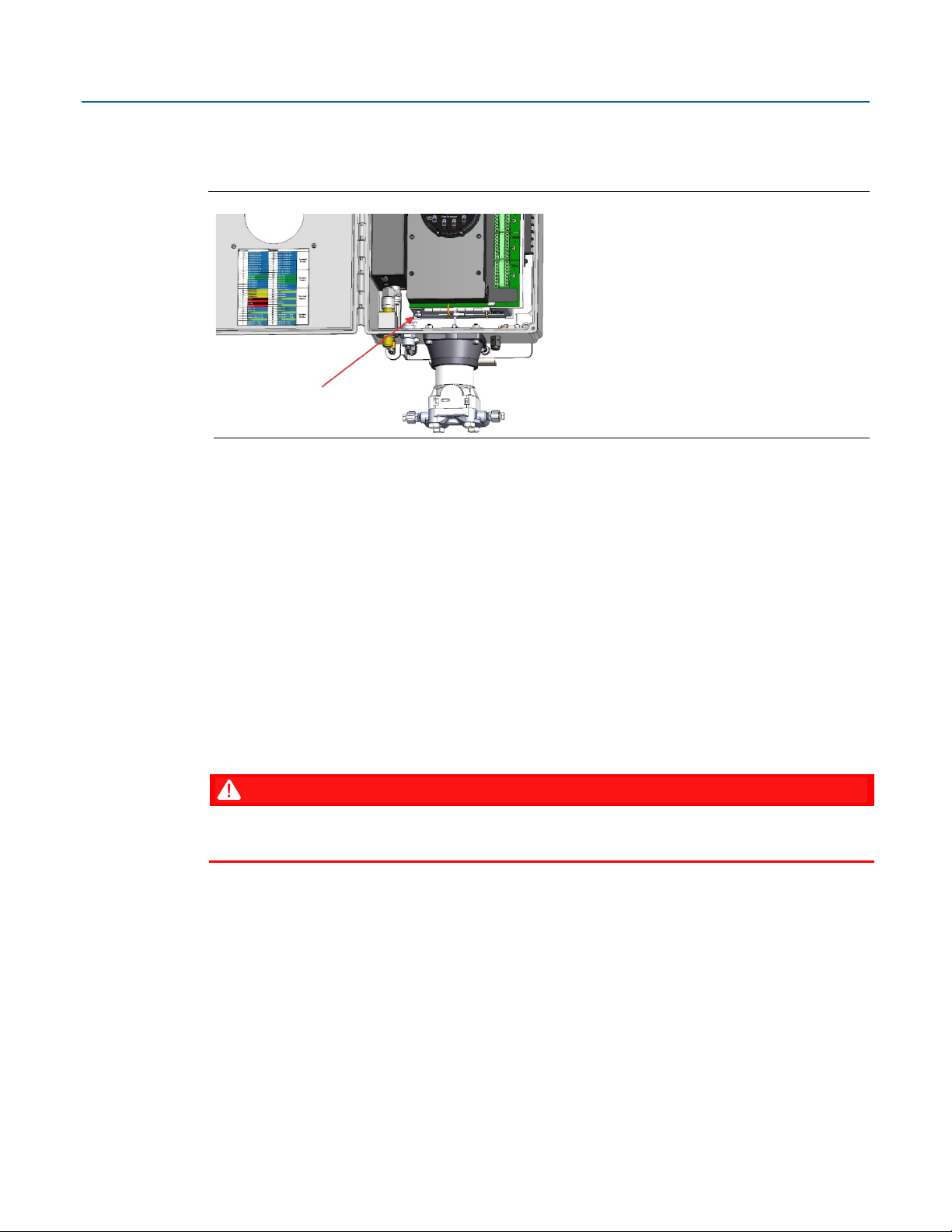
2.14 Security Intrusion Switch
If ordered from the factory, the door contact wires to a momentary switch as shown using cable
part number 399331-01-0.
Figure 2-50. Wiring the Door Contact Terminal to a Momentary Switch
Emerson FB2200 Flow Computer Instruction Manual
D301784X012
November 2020
If you order the optional security intrusion switch, the flow computer ships from the factory with
the door switch option enabled. To verify this, you can run FBxConnect software and select
> Board Info. This allows you to view/modify the enable/disable setting for the Door Switch. The
door switch is always on
Figure 2-51. Board Info Screen in FBxConnect
Module_3.
Services
Installation 61
Page 66

Emerson FB2200 Flow Computer Instruction Manual
D301784X012
November 2020
62 Installation
Page 67

Emerson FB2200 Flow Computer Instruction Manual
Section 3: I/O Configuration and Wiring
This section covers the following topics:
Analog Inputs
D301784X012
November 2020
Analog Outputs
Digital Inputs
Digital Outputs
Pulse Inputs
Connecting the RTD/PRT
Connecting a Rosemount 4088B Transmitter for Use in a Second Meter Run
Wiring a Digital Output to the Optional Relay
Radio Wiring
I/O in the FB2200 flow computer comes from the integrated multivariable sensor and RTD
connector, the CPU board, as well as the optional mixed I/O modules.
Note
When using a digital output to drive an inductive load (such as a relay coil), place a suppression
diode across the load. This protects the DO from the reverse Electro-Motive Force (EMF) spike
generated when the inductive load is switched off.
Notes About Power for an External Device Connected to a Flow Computer I/O Point:
If the external device does not include its own integrated power supply, you must provide your own
external supply (30Vdc maximum) for that device.
If your FB2200 flow computer includes the optional 8-channel Expansion I/O Module, you may be
able to use the 24V loop power terminals to power the external device. In this case, the
load current
cannot exceed 500 mA.
maximum
I/O Configuration and Wiring 63
Page 68

Emerson FB2200 Flow Computer Instruction Manual
A
When wiring a 1-5 V Analog Input (AI), use configuration at left
B
When wiring a 4-20 mA Analog Input (AI), use configuration at left
1
Field Device
2
Power Supply 30Vdc Max
3
Open Drain Type or Open Collector Device (Externally Powered)
4
500 mA load max
5
To AGND
6
To AIAOx
7
Dry contact
D301784X012
November 2020
Figure 3-1. Base I/O (AI/AO 1 & 2, DI/DO/PI 1 & 2)
64 I/O Configuration and Wiring
Page 69

Emerson FB2200 Flow Computer Instruction Manual
1
Field Device
2
Power Supply 30Vdc Max
3
500 mA load max
4
Open Drain Type or Open Collector Device (Externally Powered)
5
Dry contact
6
Low Side Switch
7
High Side Switch
Figure 3-2. Wiring for 8-channel Expansion I/O Module and 6-channel Expansion I/O Module
D301784X012
November 2020
3.1 Analog Inputs
The FB2200 flow computer includes two on-board channels you can individually configure as either
analog inputs (AI) or analog outputs (AO). The optional 8-channel expansion I/O module includes 4
additional channels you can individually configure as AIs or AOs. In addition, if you purchased the
optional 6-channel expansion I/O module, there are two additional channels you can individually
configure as either AIs or AOs.
Note
I/O Configuration and Wiring 65
Page 70

Emerson FB2200 Flow Computer Instruction Manual
Type
Number Supported
Characteristics
Analog
0 to 8 as follows:
4 to 20 mA range (@24Vdc), or 1 to
only
D301784X012
November 2020
No external resistor is required for a current (mA) device. You can apply a 250 ohm resistor using
analog input configuration selections in FBxConnect.
When configured as analog inputs, the channels have the following characteristics:
Table 3-1. Analog Input Characteristics
Input (AI)
1 or 2 non-isolated channels on CPU
module (AI/AO1 and AI/AO2) always
present. You can configure one, both,
or neither as AIs.
1, 2, 3, or 4 additional isolated
channels on optional 8-channel
expansion I/O module (ISO AI/AO3,
ISO AI/AO4, ISO AI/AO5, or ISO
AI/AO6). If module is present you can
configure any (or none) of the four
channels as AIs.
1 or 2 additional isolated channels on
optional 6-channel expansion I/O
module (ISO AI/AO7 and ISO AI/AO8).
If module is present you can configure
one, both, or neither as AIs. This
module is allowed only if 8-channel
expansion I/O module is also present.
5Vdc
Over range for calibration purposes:
3.2 to 20.8 mA or 0.8 to 5.2 Vdc
AI1 and AI2 require external power
when in current mode
Factory calibrated (re-calibration is
unnecessary for at least 3 years)
Signal conditioning
When you configure a channel as an AI
it cannot be used as an AO
66 I/O Configuration and Wiring
Page 71

3.1.1 AI Wiring
A
When wiring a 1-5 V Analog Input (AI), use configuration at left
B
When wiring a 4-20 mA Analog Input (AI), use configuration at left
1
Field Device
2
Power Supply 30Vdc Max
3
To AIAOx
4
To AGND
The following diagrams show how to wire the analog input.
Figure 3-3. AI Wiring: Base I/O (AI/AO1 & AI/AO2 only)
Emerson FB2200 Flow Computer Instruction Manual
D301784X012
November 2020
I/O Configuration and Wiring 67
Page 72

Emerson FB2200 Flow Computer Instruction Manual
1
Field Device
Type
Number Supported
Characteristics
Analog
0 to 8 as follows:
Note
avoid ground loops, which could affect
4 to 20 mA range (@24Vdc)
D301784X012
November 2020
Figure 3-4. AI Wiring: Optional 8-channel Expansion I/O Module (ISO AI/AO 3,4,5,6) and Optional 6channel Expansion I/O Module (ISO AI/AO 7,8)
3.2 Analog Outputs
The FB2200 flow computer includes two on-board channels you can individually configure as either
analog outputs (AO) or analog inputs (AI). The optional 8-channel expansion I/O module includes 4
additional channels you can individually configure as AOs or AIs. In addition, if you purchased the
optional 6-channel expansion I/O module, there are two additional channels you can individually
configure as either AOs or AIs.
When configured as analog outputs, the channels have the following characteristics:
Table 3-2. Analog Output Characteristics
Input (AI)
1 or 2 non-isolated channels on CPU
module (AI/AO1 and AI/AO2) always
present. You can configure one, both,
or neither as AOs.
: If you configure both as AOs we
recommend you provide isolation to
Externally powered field device
(Ai/AO1 and AI/AO2)
24V loop supply powers AO (ISO
AI/AO3 through ISO AI/AO8)
AO sinks current to system ground
68 I/O Configuration and Wiring
readings.
1, 2, 3, or 4 additional isolated
channels on optional 8-channel
expansion I/O module (ISO AI/AO3,
ISO AI/AO4, ISO AI/AO5, or ISO
AI/AO6). If module is present you can
Factory calibrated (re-calibration is
unnecessary for at least 3 years)
You can configure a fail state so that
on power up or if the CPU fails the
output drives to 0 µA
Page 73

Emerson FB2200 Flow Computer Instruction Manual
configure any (or none) of the four
When you configure a channel as an AO
1
Field Device
2
Power Supply 30Vdc Max
D301784X012
November 2020
3.2.1 AO Wiring
The following diagrams show how to wire the analog output.
Figure 3-5. AO Wiring: Base I/O (AI/AO1 & AI/AO2)
channels as AOs.
1 or 2 additional isolated channels on
optional 6-channel expansion I/O
module (ISO AI/AO7 and ISO AI/AO8).
If module is present you can configure
one, both, or neither as AOs. This
module is allowed only if 8-channel
expansion I/O module is also present.
it cannot be used as an AI
I/O Configuration and Wiring 69
Page 74

Emerson FB2200 Flow Computer Instruction Manual
1
Field Device
Type
Number Supported
Characteristics
Digital
0 to 8 as follows:
Circuit protection.
D301784X012
November 2020
Figure 3-6. AO Wiring: Optional 8-channel Expansion I/O Module (ISO AI/AO 3,4,5,6) and Optional
6-channel Expansion I/O Module (ISO AI/AO7 & AI/AO8)
3.3 Digital Inputs
Depending upon how you ordered it, the FB2200 flow computer includes two, six, or ten channels
you can individually configure as digital inputs (DI), digital outputs (DO), or pulse inputs (PI).
When configured as digital inputs, the channels have the following characteristics:
Table 3-3. Digital input Characteristics
Input (AI)
1 or 2 non-isolated channels on CPU
module (DI/DO/PI1 and DI/DO/PI2).
Two are always present; you can
configure one, both, or neither as DIs.
1 to 4 additional isolated channels on
optional 8-channel expansion I/O
module (ISO DI/DO/PI3 to ISO
DI/DO/PI6). If module is present you
can configure one, two, three, four, or
none of the channels as DIs.
1 to 4 additional isolated channels on
optional 6-channel expansion I/O
30ms input filtering
Maximum input frequency of 10 Hz
Selectable current source of 66 µA or 2
mA.
Either externally driven or internally
driven and pulled to ground by dry
contact closures or open collector
devices
70 I/O Configuration and Wiring
Page 75

Emerson FB2200 Flow Computer Instruction Manual
Type
Number Supported
Characteristics
module (ISO DI/DO/PI7 to ISO
When you configure a channel as a DI it
1
Dry contact
1
Dry contact
D301784X012
November 2020
3.3.1 DI Wiring
The following diagrams show how to wire the digital input.
Figure 3-7. DI Wiring: Base I/O (DI/DO/PI1 & DI/DO/PI2)
DI/DO/PI10). If module is present you
can configure one, two, three, four, or
none of the channels as DIs. This
module is allowed only if 8-channel
expansion I/O module is also present.
cannot be used as a DO or PI channel
Figure 3-8. DI Wiring: 8-channel Expansion I/O Module (ISO DI/DO/PI3,4,5,6) and 6-channel
Expansion I/O Module (ISO DI/DO/PI7,8,9,10)
I/O Configuration and Wiring 71
Page 76

Emerson FB2200 Flow Computer Instruction Manual
Type
Number Supported
Characteristics
Digital
0 to 10 as follows:
configure one, both, or neither as DOs.
DO is a low-side switch that sinks
state
D301784X012
November 2020
3.4 Digital Outputs
Depending upon how you ordered it, the FB2200 flow computer includes two, six, or ten channels
you can configure as digital outputs (DO), digital inputs (DI) or pulse inputs (PI).
Note
When using a digital output to drive an inductive load (such as a relay coil), place a suppression
diode across the load. This protects the DO from the reverse Electro-Motive Force (EMF) spike
generated when the inductive load is switched off.
When configured as digital outputs, the channels have the following characteristics:
Table 3-4. Digital Output Characteristics
Output
(DO)
1 or 2 non-isolated channels on CPU
module (DI/DO/PI1 and DI/DO/PI2).
Two are always present; you can
1 to 4 additional isolated channels on
optional 8-channel expansion I/O
module (ISO DI/DO/PI3 to ISO
DI/DO/PI6). If module is present you
can configure one, two, three, four, or
none of the channels as DOs.
1 to 4 additional isolated channels on
optional 6-channel expansion I/O
module (ISO DI/DO/PI7 to ISO
DI/DO/PI10). If module is present you
can configure one, two, three, four, or
none of the channels as DOs. This
module is allowed only if 8-channel
expansion I/O module is also present.
current to ground
Current rating of 500 mA
Maximum operating frequency of 50
Hz
Pulse off/on time can be configured
with a 31 ms minimum on-time and a
31 ms minimum off-time
Software-configurable with an output
state for initial power up and in the
case of a CPU failure
Software-configurable failure mode of
fail-open, fail-closed, or hold-last-
When you configure a channel as a DO
it cannot be used as a DI or PI channel
Note
Digital outputs are rated to 500mA maximum. In a small number of applications, however, the load
on the DO could have an effect on the uncertainty of the analog inputs and outputs. The typical
increase in uncertainty is around 0.05% and
Either of the two analog channels in the base I/O is used as an AI (in voltage mode) or as an AO
Either of the two digital channels in the base I/O is used as a DO and
The total current load on these two DOs is greater than 300mA
Analog inputs in current mode and the I/O channels in the expansion
3.4.1 DO Wiring
The following diagrams show how to wire the digital output.
72 I/O Configuration and Wiring
only occurs when all of the following are true:
and
I/O boards are not affected.
Page 77

Emerson FB2200 Flow Computer Instruction Manual
1
Power Supply 30Vdc Max
2
500 mA load max
1
500 mA load max
2
Power Supply 30Vdc Max
Figure 3-9. DO Wiring: Base I/O (DI/DO/PI1 & DI/DO/PI2)
D301784X012
November 2020
Figure 3-10. DO Wiring: Optional 8-channel Expansion I/O Module (ISO DI/DO/PI3,4,5,6) and
Optional 6-channel Expansion I/O Module (ISO DI/DO/PI7,8,9,10)
I/O Configuration and Wiring 73
Page 78

Emerson FB2200 Flow Computer Instruction Manual
3
Low Side Switch
4
High Side Switch
D301784X012
November 2020
74 I/O Configuration and Wiring
Page 79

3.5 Pulse Inputs
Type
Number Supported
Characteristics
Pulse
0 to 10 as follows:
Supports dry contacts and open
Depending upon how you ordered it, the FB2200 flow computer includes two, six, or ten channels
you can individually configure as either pulse inputs (PI), digital inputs (DI), or digital outputs (DO).
Emerson FB2200 Flow Computer Instruction Manual
D301784X012
November 2020
When configured as pulse inputs, the PI channels have the following characteristics:
Table 3-5. Pulse Input Characteristics
Inputs (PI)
1 or 2 non-isolated channels on CPU
module (DI/DO/PI1 and DI/DO/PI2).
Two are always present; you can
configure one, both, or neither as PIs.
1 to 4 additional isolated channels on
optional 8-channel expansion I/O
module (ISO DI/DO/PI3 to ISO
DI/DO/PI6). If module is present you
can configure one, two, three, four, or
none of the channels as PIs.
1 to 4 additional isolated channels on
optional 6-channel expansion I/O
module (ISO DI/DO/PI7 to ISO
DI/DO/PI10). If module is present you
can configure one, two, three, four, or
none of the channels as PIs. This
module is allowed only if 8-channel
expansion I/O module is also present.
collector outputs connected to
ground and voltage inputs
Supports single pulse for volume or
mass
Input filtering selectable at 30 µs or 1
ms
Frequency range from 0 to 10.5 KHz
Maximum input frequency for the 1
ms filter is 300 Hz
On when greater than 3.0V; off when
less than 2.0V
When you configure a channel as a PI
it cannot be used as a DI or DO
channel
I/O Configuration and Wiring 75
Page 80

Emerson FB2200 Flow Computer Instruction Manual
1
Open Drain Type or Open Collector Device (Externally Powered)
1
Open Drain Type or Open Collector Device (Externally Powered)
D301784X012
November 2020
3.5.1 PI Wiring
The following diagrams show how to wire the pulse inputs.
Figure 3-11. PI Wiring: Base I/O (DI/DO/PI1 & DI/DO/PI2)
Figure 3-12. PI Wiring: Optional 8-channel Expansion I/O Module (ISO DI/DO/PI3,4,5,6) and
Optional 6-channel Expansion I/O Module (ISO DI/DO/PI7,8)
3.6 Connecting the RTD/PRT
DANGER
76 I/O Configuration and Wiring
Page 81

Emerson FB2200 Flow Computer Instruction Manual
1
2-Wire RTD
D301784X012
November 2020
EXPLOSION HAZARD: Ensure the area in which you perform this operation is non-hazardous.
Performing this operation in a hazardous area could result in an explosion.
RTD connections reside on the terminal blocks inside the enclosure. The flow computer supports 2wire, 3-wire, and 4-wire operation. Route the RTD cable through the conduit fittings and connect
them on the terminal blocks (as shown on Figure 3-13, Figure 3-14 and Figure 3-15).
Note
The device defaults to the 4-wire RTD configuration; you can change this setting in FBxConnect.
Figure 3-13. RTD/PRT Wiring for 2-Wire
Figure 3-14. RTD/PRT Wiring for 3-Wire
I/O Configuration and Wiring 77
Page 82

Emerson FB2200 Flow Computer Instruction Manual
1
3-Wire RTD
1
4-Wire RTD
D301784X012
November 2020
Figure 3-15. RTD/PRT Wiring for 4-Wire
3.7 Connecting a Rosemount 4088B
The FB2200’s integral sensor provides data for the first meter run. Data for a second meter run
must come from an external transmitter such as the Rosemount 4088B. .
See the Rosemount™ 4088 Multivariable™ Transmitter Reference Manual (00809-0100-488, Rev. CB,
Feb. 2017) for details on installing the 4088B.
1. Connect the RS-485 terminals for COM3 to the RS-485 terminals on the 4088B using twisted
pair wire, as show in the following graphic.
78 I/O Configuration and Wiring
Page 83

Emerson FB2200 Flow Computer Instruction Manual
1
Enable termination in software
2
RS-485 bus, twisted pair required
3
Enable AC termination using switches.
4
User-provided power supply (5.4V to 30V)
Figure 3-16. Connecting a 4088B Transmitter for a Second Meter Run
D301784X012
November 2020
2. Set switches on the 4088B for bus termination or use a 120-ohm resistor.
3. Using FBxConnect, configure COM3 for RS-485 and enable termination for the port.
If the FB2200 Flow Computer does not include an integral sensor, and you want to measure two
meter runs, you must daisy-chain two external transmitters to provide data for the two meter runs.
I/O Configuration and Wiring 79
Page 84

Emerson FB2200 Flow Computer Instruction Manual
1
Enable termination in software
2
RS-485 bus, twisted pair required
3
Enable AC termination using switches.
4
User-provided power supply (5.4V to 30V)
D301784X012
November 2020
Figure 3-17. FB2200 with no integral sensor – Daisy Chain Two 4088B
80 I/O Configuration and Wiring
Page 85

Emerson FB2200 Flow Computer Instruction Manual
1
To customer load
3.8 Wiring a Digital Output to the Optional Relay
The flow computer supports two optional electro-mechanical relays for switching on/off external
circuits or devices. If you order this option, the relays ship from the factory mounted to the top of
the battery compartment inside the flow computer enclosure.
You can wire a relay to an isolated DO (Figure 3-18). You must also use the isolated GND and
provide 24V to power the relay. To attach a wire, insert it into the connector and tighten the
adjacent screw to secure it. The NO and COM wires go to the external circuit or device.
Figure 3-18. Relay Wired to Isolated DO
D301784X012
November 2020
Alternatively, you can wire a relay to a non-isolated DO (Figure 3-19). In that case, you must use the
non-isolated GND and provide 24V to power the relay. To attach a wire, insert it into the connector
and tighten the adjacent screw to secure it. The NO and COM wires go to your external circuit or
device.
I/O Configuration and Wiring 81
Page 86

Emerson FB2200 Flow Computer Instruction Manual
1
To customer load
2
Power Supply 24Vdc
1
Radio
D301784X012
November 2020
Figure 3-19. Relay Wired to Non-Isolated DO
3.9 Radio Wiring
To power a radio, you wire it to the RADIO PWR and RADIO RTN terminals. These follow whatever
the power supply provides the flow computer at the DCIN+ terminal.
Rating: DCIN @ 1A.
You must enable radio power In FBxConnect. Select Configure > System to bring up the System
screen from which you enable radio power.
Figure 3-20. Radio Wiring
82 I/O Configuration and Wiring
Page 87

Emerson FB2200 Flow Computer Instruction Manual
Section 4: Operation
This section covers the following topics:
Powering Up/Powering Down the Device
Establishing Communications
Communicating using the HMI Module
This section describes day-to-day operation of the flow computer including how to turn it on and
off and how to communicate with it.
4.1 Powering Up/Powering Down the Device
D301784X012
November 2020
DANGER
Do not attempt to connect or disconnect power from the unit in a hazardous area. Ensure the
area is non-hazardous. Failure to do so could result in an explosion.
1. Open the enclosure door.
2. Terminal block TB2 (pins 1,3,5,7) includes connections for DC power (DCIN+, DCIN-) and
battery/ solar power (BATT+, BATT-). The internal battery (which is also used with solar
power) has its own internal connectors.
This turns on (or shuts OFF) power from either an external power supply or the battery
pack/solar panel.
Note
When you turn power on, the backlight on the HMI module lights, momentarily turns off and then
remains lit while the INPUT LED blinks. After approximately one minute the initialization process
finishes and the HMI starts to display live data.
Plug in TB2 (pins 1,3,5,7) to activate DC or battery/solar power. If your device uses an
internal battery and it is not connected, connect it as discussed in 2.8.3 Connecting
Battery Power.
Unplug TB2 (pins 1,3,5,7) to deactivate DC or battery/solar power.
4.2 Establishing Communications
The flow computer supports three ways to establish communications: through the host SCADA
system, through a local laptop computer running FBxConnect, or through the HMI module.
4.2.1 Communicating with the SCADA Host
Communication to the flow computer through a SCADA host computer requires configuration of
the host computer software, which varies depending upon whether you are using OpenEnterprise
or another host software package. Much of this configuration is beyond the scope of this topic, but
no matter which host you are using, there are certain steps you must take:
Operation 83
Page 88

Emerson FB2200 Flow Computer Instruction Manual
D301784X012
November 2020
1. Decide how the SCADA host should communicate with the flow computer. This could be
through connection with one of the communication ports. A serial port connection could be
a cable directly connected to the SCADA host or there could be intermediate connections
through a radio or modem.
2. Decide which communication protocol you will use. This could be DNP3, ROC, Modbus, or
BSAP. See these documents for more information:
DNP3 Protocol Specifications Manual (for FB1000 and FB2000) (D301806X012)
ROC Protocol Specifications Manual (for Emerson FB Series Flow Computers)
(D301828X012)
FBxConnect Configuration Software User Manual (D301850X012)
BSAP Communication Guide for FB1000/FB2000 Series Flow Computers (D301808X012)
3. Provide the SCADA host with information about the various parameters it needs to extract
from the application running in the flow computer. Typically, the SCADA host software
includes a utility that allows you to identify this information so it can be incorporated into the
database at the SCADA host.
4. Using whatever human-machine interface (HMI) tools exist for the SCADA host, create
graphical displays or reports that include the parameters from the application required for
successful operator interaction (setpoints, flow variables and so on).
4.2.2 Communicating with a Laptop Using One of the Serial Ports
If the flow computer is not awake, you must wake it up first. (See Section 4.3)
Your laptop must have Field Tools software with FBxConnect software installed.
You must know a valid username/password combination for the flow computer.
DANGER
EXPLOSION HAZARD: Ensure the area in which you perform this operation is non-hazardous.
Performing this operation in a hazardous area could result in an explosion.
1. Connect a cable between a serial port (or serial/USB adapter) on your laptop and port COM2
on the flow computer.
2. Launch Field Tools and add a new serial connection for this device; this launches FBxConnect
configuration software. (If you already have an existing saved serial connection for this
device in Field Tools, just double-click on it in the Connections list.)
3. Log into the flow computer if prompted.
4. Use the FBxConnect configuration software to view or change any desired parameters.
5. When finished, log off the flow computer and disconnect the cable from its serial port.
4.2.3 Communicating with a Laptop Using Ethernet
Your laptop must have Field Tools software with FBxConnect software installed. Additionally, you
must know a valid username/password combination for the flow computer. :
84 Operation
Page 89

Emerson FB2200 Flow Computer Instruction Manual
WARNING
D301784X012
November 2020
DANGER
EXPLOSION HAZARD: Ensure the area in which you perform this operation is non-hazardous.
Performing this operation in a hazardous area could result in an explosion.
1. Connect a Category 5 shielded cable between an Ethernet port on your laptop and an
Ethernet switch for your network.
2. Connect a Category 5 shielded cable between your Ethernet switch and the Ethernet port on
the flow computer.
3. Launch Field Tools and add an IP connection for the device then click Connect to start the
FBxConnect software. (If you already have an existing saved IP connection for this device in
Field Tools, just double-click on it in the Connections list.)
4. Log into the flow computer if prompted.
5. Use the FBxConnect software to view/change any desired parameters.
6. When finished, log off from the flow computer and disconnect the cable.
4.2.4 Communicating with a Laptop Wirelessly with FBxWifi
You must have purchased the flow computer with the optional FBxWifi feature in order to connect
to a laptop PC wirelessly. Additionally:
Ensure that you and your laptop PC are in a non-hazardous area.
1. Launch Field Tools software and add a new wireless connection. (If you already have a saved
2. Select the wireless network to which the flow computer belongs and enter the appropriate
3. Click Connect to start the FBxConnect software.
®
Wi-Fi
Your laptop PC must have Field Tools software with FBxConnect installed.
You must know a valid username/password combination for the flow computer.
You must know the name of the wireless network and the security key required to connect to
it.
Your laptop PC must be within line-of-sight with either the front display of the flow computer
or of an external antenna for the FBxWifi.
If the flow computer is not awake, you must wake it up first. (See Section 4.3)
wireless connection for this device in Field Tools, just double-click on it in the Connections
list and skip to step 4.)
security key.
must be configured and working on your laptop PC.
Operation 85
4. Log into the flow computer if prompted.
5. Use the FBxConnect software to view or change any desired parameters.
6. When finished, log off the flow computer and disconnect from the wireless network.
Page 90

Emerson FB2200 Flow Computer Instruction Manual
D301784X012
November 2020
4.3 Communicating Using the HMI Module
You must have purchased the flow computer with the HMI module version that includes the
optional display. Not all models include the display. Units without the display still include a button
to wake up the device and status LEDs.
Notes:
If the device is configured to require logins to view data, you must know a valid
username/password combination for the flow computer.
To conserve power, the HMI module enters sleep mode after a period of inactivity. Sleep mode
disables FBxWifi communication. In FBxConnect, you can configure the number of minutes of
inactivity triggering sleep mode through the LCD Sleep Time parameter. Setting this
parameter to 0 disables sleep mode which keeps the HMI module on but uses significantly
more power.
To temporarily keep the HMI module out of sleep mode, maintain an active FBxConnect
connection. As long as communications remain active, the HMI module will not sleep
1. Go to the front of the flow computer and touch your finger on the glass above the Hold to
Wake button until the display lights up. (This may take several seconds.)
Figure 4-1. Waking the Display
2. If prompted, login using a valid username/password combination. For information on how
the buttons work, see Table 4-1.
The display enters Screen Saver Mode where it sequentially presents a series of screens
showing details about meter run flow rates, totals, and current process variables.
86 Operation
Page 91

Figure 4-2. Infrared (IR) Button Location
1
Left Infrared (IR) Button
2
Down Infrared (IR) Button
3
Up Infrared (IR) Button
4
Right Infrared (IR) Button
Button
Mode
Use
Tap once to move up or down one item through list
Tap (UP) once to move the cursor to the previous
Tap once to move the cursor to the left.Hold to
Tap once to move the cursor to the right.Hold to
Emerson FB2200 Flow Computer Instruction Manual
D301784X012
November 2020
Note
When using the IR buttons, aim your finger at the round spot just below the arrow.
Table 4-1. Infrared (IR) Buttons on HMI Module
OR
Operation 87
Screen Saver
of parameters.
Hold to stay on current parameter.
Data Entry
character in the list or (DOWN) once to move the
cursor to the next character in the list.Hold (UP) or
(DOWN) to scroll more quickly through the
character list.
Idle Mode Hold to wake the display (if screen is off)
Screen Saver Log out (if logged on)
Data Entry
perform action shown on screen (such as “Hold to
Accept”)
Data Entry
perform action shown on screen (such as “Hold to
Cancel”)
Page 92

Emerson FB2200 Flow Computer Instruction Manual
Symbol
Explanation
Alarm - The parameter value shown is in an alarm state (High Alarm, Low Alarm,
Override - The parameter value shown is in override mode (i.e. a user entered
Fault - The parameter value shown is somehow invalid
Unverified - For parameter values that require additional validation (beyond
D301784X012
November 2020
Symbol(s) representing the status of a value may appear in the upper right of the display, next to
the description. Multiple symbols may be shown. If there are no data quality issues, no symbols will
be shown.
Table 4-2. Symbols on Display
etc.)
fixed value)
simple database min/max range checking, the parameter value shown has not
yet been validated by the firmware).
88 Operation
Page 93

Emerson FB2200 Flow Computer Instruction Manual
Section 5: Service and Troubleshooting
This section covers the following topics:
Returning the Unit for Repairs
D301784X012
November 2020
Interpreting the Status LEDs
Switch and Buttons
Removing/Replacing the HMI Module
Replacing the Main Battery Pack
Removing/Replacing the SRAM Battery
Upgrading System Firmware
In order to maintain hazardous location certifications, you can only replace components in the field
with the exact same part so that the model string on the data plate remains correct. This means
you cannot add any hardware not reflected in the model string or upgrade a hardware component
to a newer version; any such upgrades are prohibited and void the hazardous location certification.
This chapter describes the service tasks that everyone needs to know such as replacing batteries or
installing a firmware upgrade. For other field replacements, see the appropriate field replacement
guides for that component. Any replacement not covered in this chapter or in the field
replacement guides can only be performed at an Emerson-authorized repair facility.
Important
Use only batteries supplied with the flow computer or sold by Emerson Remote Automation
Solutions as spare parts for this flow computer. If you substitute a battery you obtain elsewhere you
will void your certification unless it is the identical part from the same manufacturer as that supplied
with the flow computer from Emerson.
Service and Troubleshooting 89
Page 94

Emerson FB2200 Flow Computer Instruction Manual
1
HMI module
2
CPU enclosure cover
3
SRAM backup battery
4
CPU enclosure
5
I/O termination board
6
Battery compartment cover
7
Battery compartment
8
Battery
9
Enclosure
10
Sensor assembly
D301784X012
November 2020
Figure 5-1. FB2100 Flow Computer Components
90 Service and Troubleshooting
Page 95

Emerson FB2200 Flow Computer Instruction Manual
WARNING
1
Input LED
2
Link LED
3
Status LED
4
Alarm LED
5.1 Returning the Unit for Repairs
Only certain field replacement procedures are allowed under warranty and hazardous location
certification. Other types of repairs cannot be performed in the field. In those cases, you must ship
the unit to an Emerson-authorized repair facility. Contact Emerson Remote Automation Solutions
for a return authorization number and instructions for where to ship the unit.
International safety regulations restrict the shipment of lithium batteries. If you need to return
the flow computer, remove the lithium battery before you ship the unit. Failure to remove the
lithium battery may delay or prevent shipment of the flow computer.
5.2 Interpreting the Status LEDs
There are four (4) status LEDs on the flow computer. The meaning of each LED varies depending
upon the color displayed or whether the LED flashes.
Figure 5-2. LED Locations
D301784X012
November 2020
Service and Troubleshooting 91
Page 96

Emerson FB2200 Flow Computer Instruction Manual
LED
Color/State
Meaning
Link LED
GREEN
An active wired Ethernet connection exists.
Input LED
GREEN
One of the IR buttons is being pressed.
Flashing YELLOW
CPU booting or CPU has not yet recognized HMI
Status LED
GREEN
OK - Normal
RED
Unit failed
YELLOW
Low power source/change battery soon
Off
No power
Flashing GREEN
System is booting
Momentary GREEN –
HMI module is in sleep mode (to reduce power
Alternating RED, GREEN,
HMI module boot firmware loaded but no
Alarm LED
GREEN
No alarms
Flashing RED
HMI firmware update in progress.
RED
Alarms are present.
LED Sequence
Color/State
HMI module failed. Replace with spare or
Link and Alarm alternately flash RED; sequence
CPU stuck in boot mode. Contact technical
D301784X012
November 2020
Table 5-1. LED Descriptions
Otherwise it is off. (FB1200/FB2200 only)
module when HMI first powered on; goes off
when recognized.
(FB1100 with lithium battery only)
approximately every 6
seconds
YELLOW
consumption); LED goes on when HMI module
checks the “Hold to Wake” IR button.
application is present. You may see this during
an HMI firmware update.
Table 5-2. Special LED Sequences using Multiple LEDs
Link, Input, Status, and Alarm all solid RED
repeats
return for repairs.
support.
92 Service and Troubleshooting
Page 97

5.3 Switch and Buttons
Button Name
Purpose
Procedure
SYSTEM RESET
Resets Power. This momentary
Move the SYSTEM RESET switch either
A
Clears memory (SRAM). The
B
Currently undefined
A momentary switch and two push buttons on the HMI module provide troubleshooting options
for the flow computer.
Figure 5-3. Switch and Buttons
Emerson FB2200 Flow Computer Instruction Manual
D301784X012
November 2020
DANGER
EXPLOSION HAZARD: Never open the enclosure in a hazardous location. Opening the enclosure in
a hazardous location could result in an explosion.
Table 5-3. Switch and Buttons
switch Interrupts power to the
flow computer to reset it. Used if
system powered on but nonfunctional; this attempts a reboot.
SRAM memory holds current data
values and pending alarm
messages. If unit has unexpectedly
stopped operating, you can
depress this button on power- up
to clear that information from
memory (hard reset). Try this if a
SYSTEM RESET alone does not
work.
up or down. Unit powers off and then
restarts.
Press and hold the A button.
While continuing to hold the A button,
move the SYSTEM RESET switch either
up or down to initiate a reset.
Release the A button. The system clears
SRAM during the power up sequence.
Service and Troubleshooting 93
None
Page 98

Emerson FB2200 Flow Computer Instruction Manual
D301784X012
November 2020
5.4 Removing/Replacing the HMI Module
You do not need to power down the unit to remove/replace the HMI module.
DANGER
Ensure the flow computer is in a non-hazardous area. Never remove/replace the HMI module in a
hazardous area.
1. Open the enclosure.
2. Loosen the four captive fastening screws on the HMI module.
Figure 5-4. Captive Fastening Screws
3. Grasp the HMI module and remove it by gently pulling it straight out.
4. To replace the HMI module, line up the printed circuit board (PCB) with the slot on the back
and gently press it back on. Tighten the four captive fastening screws.
5. Close the enclosure.
5.5 Replacing the Main Battery Pack
Periodically you must replace the main battery pack.
94 Service and Troubleshooting
Page 99

Figure 5-5. Main Battery Pack
Emerson FB2200 Flow Computer Instruction Manual
D301784X012
November 2020
The device provides a battery cable with two pairs of battery connectors, enabling you to hot-swap
the battery pack in a non-hazardous location. You attach the new battery pack to the free
connector (leaving the old one connected), and then disconnect the old battery pack.
DANGER
EXPLOSION HAZARD: Ensure the area in which you perform this operation is non-hazardous.
Performing this operation in a hazardous area could result in an explosion.
DANGER
EXPLOSION HAZARD: Do not disconnect equipment unless power has been removed or the area
is known to be non-hazardous.
Service and Troubleshooting 95
Page 100

Emerson FB2200 Flow Computer Instruction Manual
WARNING
D301784X012
November 2020
DANGER
EXPLOSION HAZARD: Substitution of any components may impair suitability for Class I, Division
2.
DANGER
EXPLOSION HAZARD: Do not replace batteries unless power has been switched off or the area is
known to be non-hazardous. Batteries must only be changed in an area known to be nonhazardous.
There are no user-serviceable parts inside the battery pack. Do not open the battery pack as you
may damage the battery pack or injure yourself.
You need a Phillips-head screwdriver to perform this procedure.
Keep the replacement battery pack handy during the procedure.
1. Remove the plastic tabs covering the connectors on the new battery pack.
Figure 5-6. Remove Plastic Tabs from New Battery Pack
2. Open the enclosure.
3. Loosen the two captive fastening screws at the top of the of the battery compartment and
hold the battery compartment door as you carefully rotate the electronics assembly towards
you to reveal the inside of the battery compartment. A strap prevents the front of the
compartment from rotating too far forward.
96 Service and Troubleshooting
 Loading...