

Page 1
Process Management
TM
PRESSURE REGULATORS
Europe, Middle East, and Africa Only
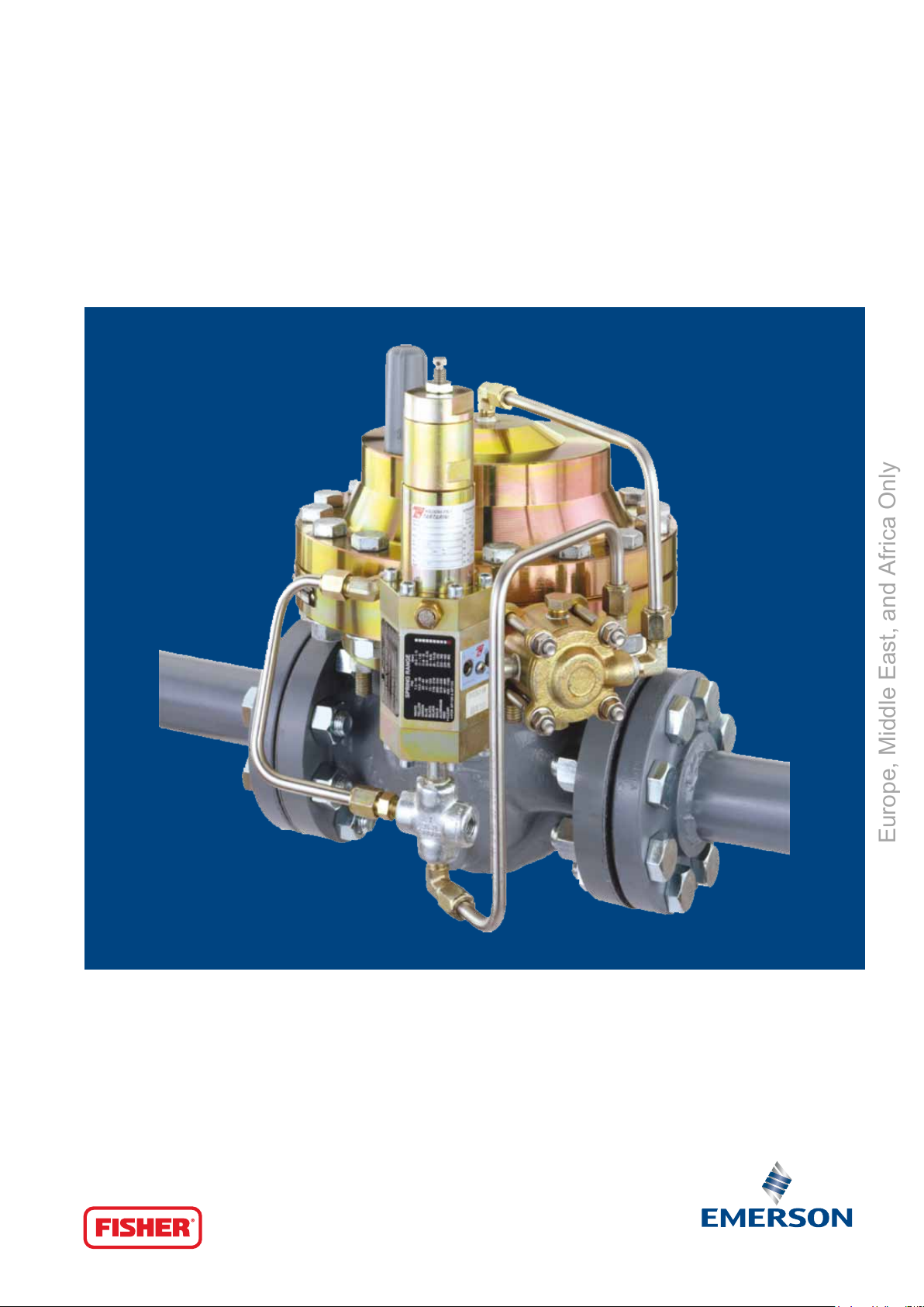
Type EZH and EZHSO
Page 2
EZH and EZHSO Regulators
Europe, Middle East, and Africa Only
Pressure Regulators
Type EZH and EZHSO (Spring-to-Open) regulators are accurate pilot-operated, pressure balanced, soft seated regulators.
They are designed for use in high pressure natural gas transmission/city gate stations, large capacity distribution systems, and
power plant feeds. They provide smooth, reliable operation, tight shutoff and long life.
The main benefits are as follows:
• Longlifeinsevereserviceapplications
• Highresistancetoaromaticsandparticleerosion
• Noiseattenuationmodule(optional)
• Highturndowncapacityforsystemswithlargevariationsindownstreamflowdemand
• Absolutelynobleedtoatmosphere
• Widerangeofflowcoefficientsforeachbodysize
• Bubbletightshutoff
• Accuratepressurecontrol
• Lowtemperaturestandardversion
• Integralstrength
• Easymaintenancesystem
• Spring-to-closeandspring-to-openversions
• Long life in severe service applications: The Type EZH
and EZHSO utilize a metal plug design to deect particles
and debris away from the soft-seat, which gives enhanced
resistance to particle erosion to provide a longer service life.
In addition, the Type EZH and EZHSO can be constructed with
uoroelastomer soft parts to extend service life in applications
where liquid aromatics are entrained in the gas.
• High turn down capability: The oversized diaphragm and
unique piloting system of the Type EZH and EZHSO allow for
a 100:1 turn down ratio, which will provide superior pressure
control in systems with large variations in downstream ow
demand.
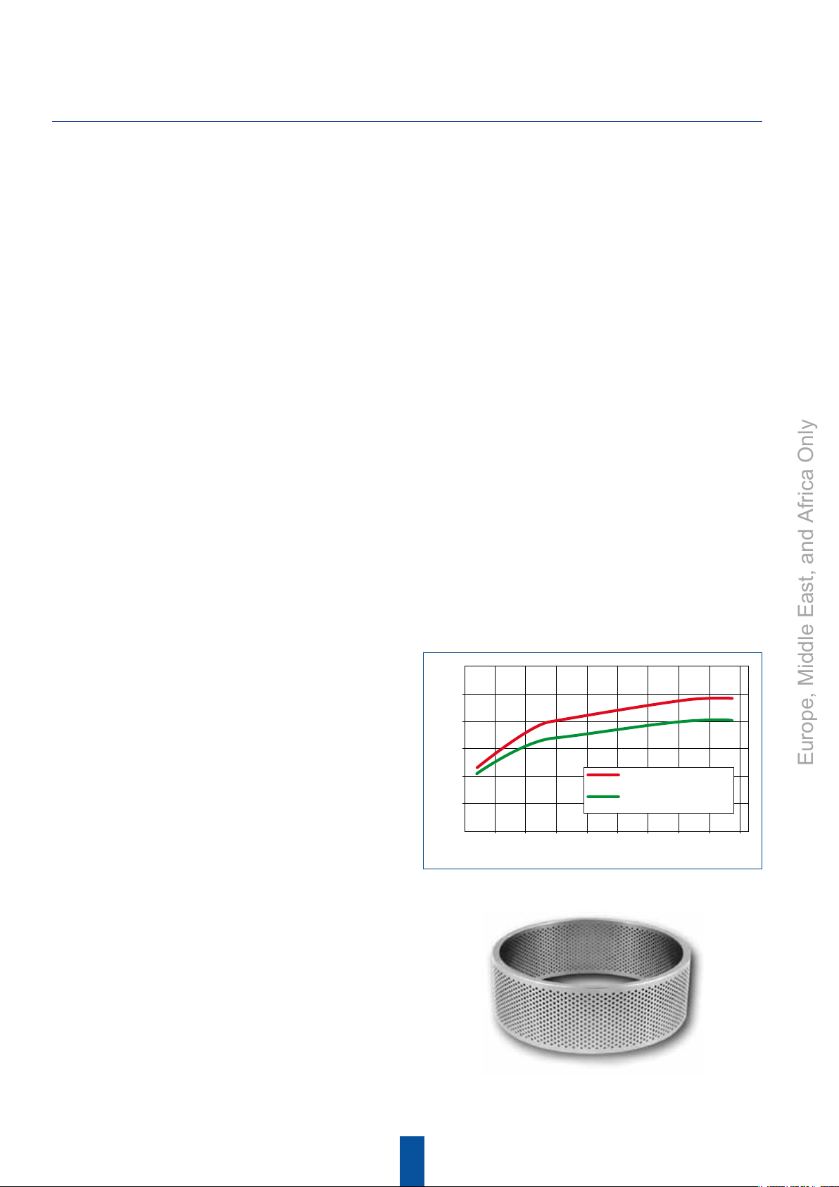
• Noise attenuation module: The EZH and EZHSO offer an optional
Whisper Trim Cage which is integral to the regulator therefore
maintaining the advantages of it's compact design. The Whisper
Trim Cage is available on DN 50, 80 and 100. It allows for a noise
attenuation up to 8 dB.
110
100
90
80
70
NOISE LEVEL (dBA)
60
50
9400
EZH AND EZHSO SERIES WITH
STANDARD CAGE
EZH AND EZHSO SERIES WITH
WHISPER TRIM® CAGE
18900 28400 37500 47100 56800 66200 75700 851000
FLOW RATE (Nm3/h)
Noise Comparison Diagram
• Absolutely no bleed to atmosphere: The Type EZH
and EZHSO eliminate nuisance and wasteful bleed gas to
atmosphere by utilizing a pilot-operated control system,
which bleeds 100% of the gas to the downstream system
while the regulator is operating.
• Wide range of flows coefficients for each body size:
EZH and EZHSO offer the possibility of ow reduction ranges
according to each body size. This is achieved by simply
replacing the standard seat by a reduction seat.
The
Whisper Trim Cage
2
Page 3
• Bubble tight shutoff: The Type EZH and EZHSO have a knife-
Europe, Middle East, and Africa Only
edged, metal plug and a soft seat which provides bubble
tight shutoff for use in applications where positive shutoff is
required. For example: dead-end systems.
• Accurate pressure control: The Type EZH and EZHSO use the
Type PRX and SA/2 pilot system to provide stable and accurate
downstream pressure control regardless of load changes or
inlet pressure variations.
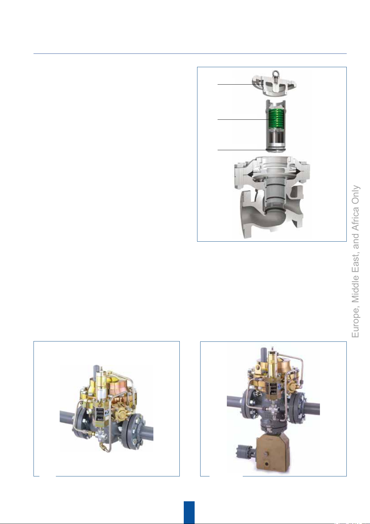
• Easy maintenance system: A top entry design reduces
maintenance time. Trim parts can be inspected, cleaned
and replaced without removing the body from the pipeline.
An innovative system has been designed for the EZH DN
100 which allows maintenance to be carried out by a single
operator. Maintenance is carried out by simply removing the
top plug, extracting the trim assembly (12.3 kg), removing
the pad holder and then changing the pad. Easy and fast
maintenance, no special tools requirement, makes the EZH
ownership low in cost.
• Spring-to-close and spring-to-open versions: Optional
positions to choose from in case of main valve diaphragm
failure or lack of supply pressure to the pilot. See table on
page 6 for "Failure Mode Analysis".
EZH and EZHSO Regulators
Plug
Trim assembly
Pad holder
EZH DN 100 Patent Pending Easy Maintenance System
Configurations
Type EZH: Pilot-operated pressure reducing regulator for low to high outlet pressure.
Type EZH-OS2: Type EZH pressure reducing regulator with an OS2 slam-shut device for overpressure or overpressure and
underpressure protection.
Type EZHSO: Spring-to-Open pilot-operated pressure reducing regulator for low to high outlet pressure.
Type EZHSO-OS2: Type EZHSO pressure reducing regulator with an OS2 slam-shut device for overpressure or overpressure and
underpressure protection.
EZH EZH-OS2
3
Page 4

EZH and EZHSO Regulators
Europe, Middle East, and Africa Only
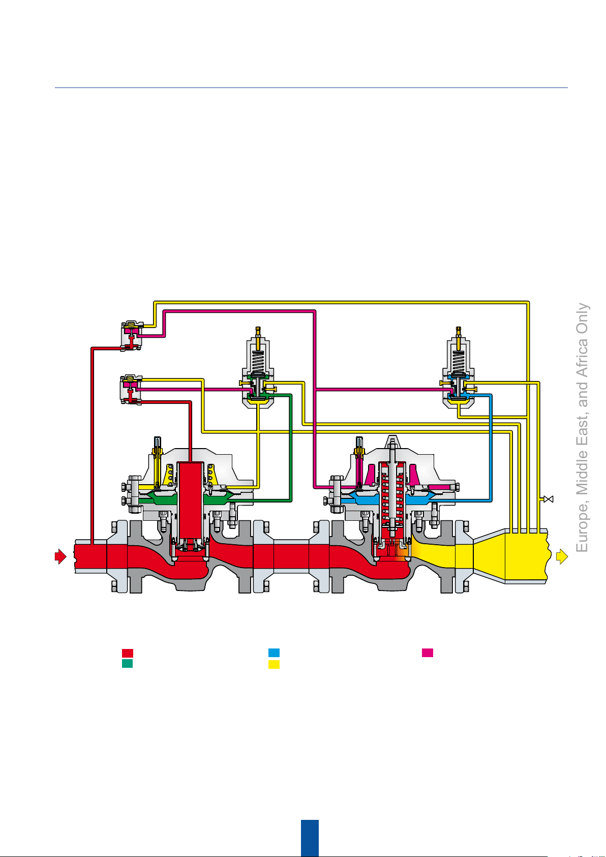
Operation
PRX/120
PRX/120-AP
SA/2
V
R
M
B
S
L
A
V
SA/2
M
R
PRX/120
PRX/120-AP
S
L
B
A
EZH Regulator
Inlet pressure Regulator motorization pressure
Outlet pressure Stabilized pressure
EZHSO Regulator
The pilot-operated type EZH uses inlet pressure as the operating medium, which is reduced through pilot operation to load the
actuator diaphragm. Outlet pressure (Pd) opposes the motorization pressure (Pm) in the actuator and also opposes the pilot control
spring. Type EZHSO Spring-to-Open version uses inlet pressure as the operating medium, which is reduced through pilot operation to
load the actuator diaphragm (lower chamber). The upper case of Type EZHSO actuator is filled with pressure coming from stabilizer
filter Type SA/2. This pressure on the upper chamber of the regulator actuator diaphragm opposes the main spring force that tends
to open the regulator. The outlet pressure opposes the pilot control spring.
For the start-up of Type EZHSO, it’s necessary to install a
vent valve in type PRX pilot bleed line connection (line from port S to downstream pipe) in order to vent the pressure from actuator lower
chamber to close the regulator.
Opening
When the outlet pressure (Pd) drops below the setting of the pilot control spring, pilot control spring force on the pilot diaphragm
thus opens the pilot valve plug, providing additional motorization pressure (Pm) to the actuator diaphragm. This diaphragm
motorization pressure opens the main valve plug, supplying the required flow to the downstream system. Any excess motorization
pressure on the actuator diaphragm escapes downstream through the bleed restriction in the pilot.
Closing
EZH -
When the gas demand in the downstream system has been satisfied, the outlet pressure (Pd) increases. The increased pressure
is transmitted through the downstream control line and acts on the pilot diaphragm. This pressure exceeds the pilot spring setting and
moves the diaphragm, closing the orifice. The motorization pressure (Pm) acting on the main diaphragm bleeds to the downstream
system through a bleed restriction in the pilot.
EZHSO - When the outlet pressure (Pd) increase over the setting of the pilot spring, the pilot valve disk will be closed, reducing motorization
pressure (Pm) to the lower chamber of the regulator actuator diaphragm; the pressure in the upper chamber will force the regulator to close.
Adjustment
The adjustment of the regulator is performed by means of the pilot adjusting screw, which causes variation of the compression of the
control spring. Adjustment is performed while the regulator is in operation with the aid of a pressure gauge to monitor downstream
pressure. The shut-off valve downstream of the regulator must not be completely closed, it is necessary that a small quantity of gas
flows downstream to allow the outlet side to vent when it is necessary to lower the pressure.
4
Page 5
EZH and EZHSO Regulators
Europe, Middle East, and Africa Only
Operation
Monitoring System
Monitoring regulation is overpressure protection by containment, therefore, there is no relief valve to vent to the atmosphere.
When the working regulator fails to control the pressure, a monitor regulator installed in series, which has been sensing the
downstream and control pressure, goes into operation to maintain the downstream pressure at a slightly higher level than normal
pressure.
During an overpressure situation, the monitoring system keeps the customer on line.
Wide-Open Monitoring Systems
SA/2
V
R
M
SA/2
V
PRX/120
PRX/120-AP
S
PRX/120
PRX/120-AP
S
R
M
EZH Monitor EZHSO Regulator
Inlet pressure
Monitor motorization pressure
B
L
A
Regulator motorization pressure
Outlet pressure
B
Stabilized pressure
L
A
This figure shows an upstream wide open monitor Type EZH and a downstream active regulator Type EZHSO (Spring-to-Open).
In this installation, if the Type EZHSO no longer controls the outlet pressure, it will remain open, letting the Type EZH regulator to
reach the required outlet pressure.
In case of failure of the Type EZH, it will close and protect the downstream system from overpressure condition.
5
Page 6
EZH and EZHSO Regulators
Europe, Middle East, and Africa Only
Operation
Working Monitoring System
SA/2
M
SA/2
V
R
V
R
M
B
PRX/125
PRX/125-AP
S
L
A
B
PRX/120
PRX/120-AP
S
L
A
PRX/120
PRX/120-AP
S
B
L
A
EZH Monitor EZH Regulator
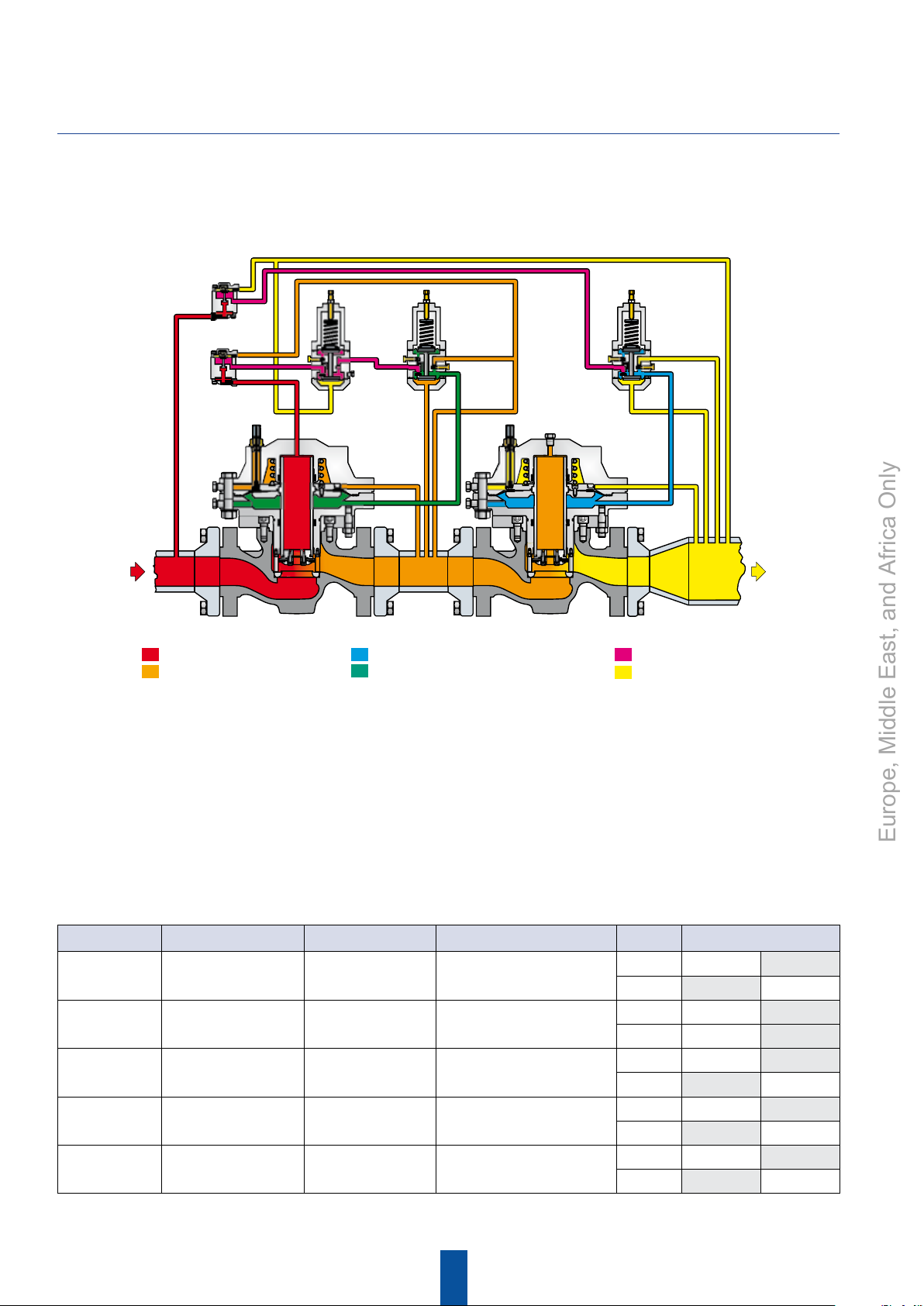
Inlet pressure
Intermediate pressure
Regulator motorization pressure
Monitor motorization pressure
Stabilized pressure
Outlet pressure
In a working monitoring system, the upstream regulator requires two pilots and it is always the monitoring regulator. In this way,
both units are always operating and can be easily checked for proper operation. In normal operation, the working regulator controls
the outlet pressure of the system. The monitoring regulator’s working pilot PRX/120 or PRX/120-AP controls the intermediate
pressure and the monitor pilot PRX/125 or PRX/125-AP senses the system’s outlet pressure. If the working regulator fails, the
monitoring pilot PRX/125 or PRX/125-AP will sense the increase in outlet pressure and take control. The working regulator must be
rated for the maximum allowable operating pressure of the system because this will be its inlet pressure if the monitoring regulator
fails. Also, the outlet pressure rating of the monitoring pilot PRX/125 or PRX/125-AP and any other components that are exposed to
the intermediate pressure must be rated for full inlet pressure. Working monitor installations require a Type EZH or EZHSO main valve
with a Type PRX/120 or PRX/120-AP working pilot and a Type PRX/125 or PRX/125-AP monitoring pilot for the upstream regulator,
and a Type EZH or EZHSO with the appropriate Type PRX/120 or PRX/120-AP pilot for the downstream regulator.
Failure Mode Analysis
Part Name Failure (Worst Case) Cause of Failure Effect Typ e Regulator Reaction Mode
Filter Filter blocked / clogged Dirty gas
Pilot Disk Pilot cannot be closed
Pilot Lower
Diaphragm
Pilot Upper
Diaphragm
Regulator
Diaphragm
Pilot cannot control
Pilot cannot feed the
regulator
Not proper performance
of the motorization
pressure chamber
Dirty gas
(microparticles),
sour gas
Fabric quality,
sour gas
Fabric quality,
sour gas
Fabric quality,
sour gas
Decrease of feeding pressure
gives decrease of
motorization pressure
Increase motorization pressure
Decrease motorization pressure
Decrease motorization pressure
Balancing of pressures and charge
or discharge of the motorization
pressure chamber
EZHSO Open
EZH Close
EZHSO Open
EZH Open
EZHSO Open
EZH Close
EZHSO Open
EZH Close
EZHSO Open
EZH Close
6
Page 7

Features
Europe, Middle East, and Africa Only
Applications
EZH and EZHSO series regulators are used in reduction, distribution and conveying stations of suitably filtered
natural gas. They can also be used for air, propane, butane, LPG, city gas, nitrogen, carbon dioxide and
hydrogen.
Technical Features
EZH and EZHSO Regulators
Allowable pressure PS
Inlet pressure P
Set range P
Min. operating differential pressure
Max. operating differential pressure
Functional Features
Accuracy class
Lock-up pressure class SG : up to + 5%
Class of lock-up pressure zone SZ : up to 5%
Operating temperature TS : -20 / 60 °C
Shut-off device
Max. operating differential pressure ∆p
Response time ta : < 1 s
Accuracy class
Set pressure range W
u
d
Type EZH ∆p
Type EZHSO ∆p
Type EZH ∆p
Type EZHSO ∆p
Type EZH AC : up to ± 1%
Type EZHSO AC : up to ± 2.5%
Diaphragm and bellows version AG : up to ± 2.5%
Piston version AG : up to ± 5%
du
: up to 100 bar
: 1 to 100 bar
: 1 to 80 bar
: 1 bar
min
: 3.8 bar
min
: 99 bar
min
: 96.2 bar
min
: 99 bar
max
- Wdo : 0.010 / 100 bar
Materials
Flanged connections
Same Inlet and outlet: DN 25 - 50 - 80 - 100*
* Available only for EZH and EZH-OS2 configurations
Flange rating: PN 16 B - PN 25 B - PN 40 B
ANSI 150 RF - ANSI 300 RF - ANSI 600 RF
Body Steel
Connecting parts and bottom Steel
Actuator Steel
Regulator / Slam-shut orifice Stainless steel
Regulator valve plug Stainless steel
Slam-shut valve plug Stainless steel
Regulator plug disc Nitrile or fluorcarbon (FKM)
Slam-shut O-rings Nitrile or fluorcarbon (FKM)
7
Page 8

EZH and EZHSO Regulators
Europe, Middle East, and Africa Only
Calculation Procedures
Symbols
Q = Natural gas flow rate in Stm3/h
P1 = Absolute inlet pressure in bar
P2 = Absolute outlet pressure in bar
= Flow rate coefficient
C
g
C1 = Body shape factor
d = Relative density of the gas
Flow Coefficients
Reduction
DN
0
Qf
C
g
C1
Regulator travel (mm) 9 17 25 30 9 17 25 30
Slam-shut travel (mm) 15 30 50
1
2
3
0
1
2
3
0
1
2
3
284 1078 2247 3567 280 1088 2266 3696
210 908 1684 2969 218 829 1698 2902
126 671 1058 1763 128 607 1066 1784
79 385 685 1062 81 370 690 1072
550 2092 4359 6920 544 2110 4396 7170
408 1762 3266 5760 423 1609 3294 5630
245 1301 2052 3420 249 1177 2069 3460
154 746 1328 2060 157 718 1339 2080
31.3 38.3 30.6 32.4 35.5 33.5 30.8 31.4
34.3 35.3 33.9 35.2 38.7 31.9 33.9 34.2
33.6 36.6 37.8 37.4 39.7 35.6 37.8 36.3
32.1 40.8 33.6 37.1 39.3 38.2 33.6 37.3
Slam-Shut (X Body) Without Slam-Shut (E Body)
25 DN 50 DN 80 DN 100 DN 25 DN 50 DN 80 DN 100
TYPE EZH DN25,50,80 and 100 - TYPE EZHSO DN 25, 50 and 80
Flow Rate Q
Sub-critical state with:
Q = 0.525 ⋅ C
N.B. the sine argument is expressed in sexagesimal degree.
Critical state with:
⋅ P1⋅ sine
g
P2 ≤
P2 >
3417
P1
C1
P1
2
P1-P2
⋅
°
P1
2
Q = 0.525 ⋅ C
g
⋅ P1
For other gases with different densities, the flow rate
calculated with the above formulas must be multiplied by
the correction factor:
0.6
F=
d
8
Gas
Air 1 0.78
City gas 0.44 1.17
Butane 2.01 0.55
Propane 1.53 0.63
Nitrogen 0.97 0.79
Carbon dioxide 1.52 0.63
Hydrogen 0.07 2.93
Relative Density
d
Factor
F
Page 9

DN Sizes
Europe, Middle East, and Africa Only
EZH and EZHSO Regulators
Calculate the required Cg with the following formula:
2
P2 >
P2 ≤
⋅
P1
2
Q
3417
⋅
C1
P1
2
1 - 0.002 ⋅ P
1 + P
u
P1 - P2
P1
u
°
Sub-critical with:
Cg =
0.525 ⋅ P1 ⋅ sine
N.B. The sine argument is expressed in sexagesimal degree.
Critical state with:
=
C
g
N.B. The above formulas apply to natural gas flow rate only. If the flow rate value (Q) refers to other gasses, divide it by the
Select the diameter of the regulator with Cg higher than calculated value.
After finding the DN of the regulator, check that gas speed on the seat does not exceed 120 m/sec, using the
following formula:
V = 345.92 ⋅
Q
0.525 ⋅ P1
correction factor F.
Q
DN
V = Velocity (m/s)
345.92 = Numerical constant
Q = Flow rate under standard conditions (Stm3/h)
DN = Regulator nominal diameter (mm)
= Inlet pressure in relative value (bar)
P
u
Advanced Design Tools
9
Page 10

EZH and EZHSO Regulators
MECHANISM
BOX
LOCATION
FOR SWITCH
RESET PIN WITH
WHITE DOT
CLIP
SLIDING CLEVIS
STEM
SCREW AND
FLAT WASHER
TRIPPING PLATE
MANOMETRIC SENSING
DEVICE (BM1)
MANOMETRIC DEVICE
THREADED STEM
SECOND STAGE
RELEASING SHAFT
TRAVEL STOP
RESETTING TOOL
CAP SCREW
BONNET
2B
Europe, Middle East, and Africa Only
Slam-Shut Device
The optional slam-shut device can provide either overpressure or overpressure and underpressure protection by completely shutting
off the ow of gas to the downstream system. The slam-shut has a mechanism box and a manometric device. The manometric device
is a spring and diaphragm actuator. Its movement activates the detection stage of the mechanism box.
The shutoff is a two stage process, the detection stage and the power stage. This separation between detection stage and power
stage provides maximum precision, alleviating many false trips caused by environmental vibrations.
The slam-shut device includes a bypass valve that will allow pressure to be equalized when resetting the device. Once the slam-shut
device has been tripped, it must be manually reset.
For more information about the Type EZH and EZHSO with a slam-shut device, contact the local Sales Representative or Sales Ofce.
Spring Adjustment Ranges (BMS)
BMS Max. Only Min. Only Max. & Min.
Wdso Setting (bar) Wdsu Setting (bar) Wdsu Setting (bar)
Typ e Size
PMS
box
(bar)
Max.
low pt.
possible
Recommended Range
Max.
low pt.
Max.
high pt.
Min.
low pt.
possible
Recommended Range
Min.
low pt.
Min.
high pt.
Min.
low pt.
possible
Max.
high pt.∆1(bar)
0.010 0.015 0.035 0.010 0.015 0.035 0.010 0.035 0.004 0.010
0.025 0.040 0.080 0.025 0.040 0.080 0.025 0.080 0.005 0.025
0.045 0.080 0.140 0.045 0.080 0.150 0.045 0.140 0.010 0.050
162 10
0.070 0.070 0.240 0.070 0.070 0.240 0.070 0.240 0.014 0.060
0.115 0.140 0.380 0.115 0.150 0.400 0.115 0.380 0.018 0.150
0.140 0.300 0.750 0.140 0.300 0.650 0.140 0.750 0.050 0.350
Diaphragm
0.250 0.600 1.3 0.250 0.600 1.15 0.230 1.3 0.080 0.600
0.450 1.2 2.3 0.450 1.1 2.0 0.450 2.3 0.170 1.1
1.0 2.0 5.1 1.0 2.0 4.7 1.0 5.1 0.350 2.5
071 20
2.1 4.0 11.0 2.1 4.0 9.5 2.1 11.0 0.700 5.5
4.0 8.0 16.0 4.0 8.0 14.4 4.0 16.0 1.6 10.0
027 100
Piston
017 100
236 35
Bellows
315 72 17.5 35.0 72.0 17.5 28.0 65.0 17.5 72.0 5.0 33.0
16.0 16.0 22.0 16.0 16.0 19.0
22.0 22.0 40.0 19.0 19.0 38.0 6.5
40.0 40.0 55.0 38.0 38.0 50.0 7.0
Not possible with
only 1 BMS
55.0 55.0 100.0 50.0 50.0 90.0 12.0
5.5 11.0 22.0 5.5 11.0 16.0 5.5 22.0 1.6 10.0
8.3 16.0 35.0 8.3 16.0 28.0 8.3 35.0 2.5 20.0
Intervals
∆1&∆2
∆2
(bar)
3.0
BM1 BMS1
Mechanism Box (BM1) with
One Manometric
Sensing Device (BMS1)
BM2BMS
Mechanism Box (BM2) with
Two Manometric Sensing
Devices (BMS1 and BMS2)
MS1
OS2 Internal Parts
10
Page 11
Applications and Construction Guide
BK
BU
BN
A
B
C
NF --> BK(A)/BU(B)
NO --> BK(A)/BN(C)
WIRING
Europe, Middle East, and Africa Only
EZH and EZHSO Regulators
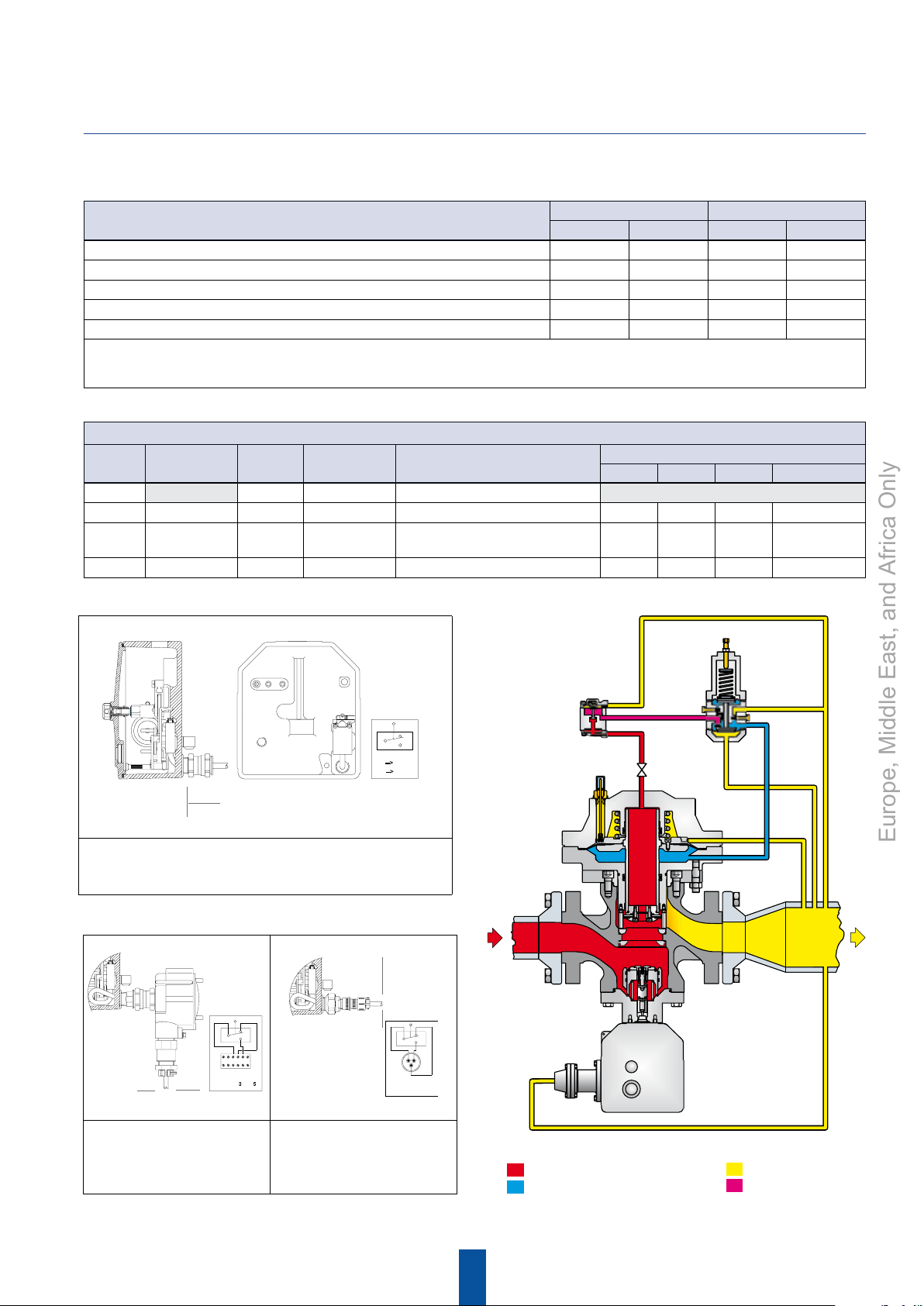
Application
Mechanism Box Manometric Sensing Device
BM1 BM2 BMS1 BMS2
Overpressure Shut-off (OPSO) Yes No Yes No
Underpressure Shut-off (UPSO) Yes No Yes No
Overpressure Shut-off (OPSO) and Underpressure Shut-off (UPSO) Ye s No Yes
Overpressure Shut-off (OPSO) and Underpressure Shut-off (UPSO) No Yes Yes
(1)
(2)
No
Yes
Overpressure Shut-off (OPSO), Overpressure Shut-off (OPSO) and Underpressure Shut-off (UPSO) No Yes Yes Yes
1. When using one manometric sensing device (BMS1) for both overpressure and underpressure shutoff, make sure that the difference between set pressures falls
within the maximum range shown in above table "Spring Adjustment Ranges".
2. When using two manometric sensing devices (BMS1 and a BMS2), the BMS1 can only be used for high trip.
Versions of Explosion Proof Limit Switches
Versions Installment Tightness Connection Mechanical connections
Common NF NO Connection
Electrical connections
C0 IP 68 Without Cap 1/2 NPT
C1 Explosion proof IP 68 Explosion proof 3 m wire Black Blue Brown Wires
C2 Explosion proof IP 65 Explosion proof
Connector box explosion proof
PE explosion proof
3 4 5 Screwed wiring
C3 Intrinsically safe IP 68 Explosion proof Intrinsically safe tight-shut connector A B C Welded wiring
PRX/120
PRX/120-AP
3 m
C1ContactVersion
Explosion proof connection with
cable and tight-shut packing gland
WIRING
BK
123456
NF --> BK(3)/BU(4)
NO --> BK(3)/BN(5)
C2ContactVersion
Explosion proof connection
with explosion proof
connector box
NF : Normally Closed
NO : Normally Open
BU
BN
C3ContactVersion
Explosion proof connection with
tight-shut connector for
intrinsically safe
WIRING
BK
NF --> BK/BU
NO --> BK/BN
SA/2
V
BU
BN
R
M
B
S
L
A
EZH-OS2
Inlet pressure
Regulator motorization pressure
Outlet pressure
Stabilized pressure
11
Page 12

EZH and EZHSO Regulators
Europe, Middle East, and Africa Only
Pilots
The Type EZH and EZHSO pressure reducing regulator includes a PRX Series pilot mounted on the Type EZH and
EZHSO main valve for pressure reducing or wide-open monitoring applications.
PRX Series pressure reducing pilots have the ability to handle a wide range of set points from 1 to 80 bar:
Type PRX/120
Outlet pressure range of 0.5 to 42 bar. The Type PRX/120 can be used as the pilot on single stage pressure reducing
regulators or as the monitor pilot or as the working pilot in wide-open monitor systems.
Type PRX/120-AP
Outlet pressure range of 30 to 80 bar. The Type PRX/120-AP can be used as the pilot on single stage pressure reducing
regulators or as the monitor pilot or as the working pilot in wide-open monitor systems.
Type PRX/125
Identical to the Type PRX/120 except the restriction screw is removed. The Type PRX/125 can only be used as the
monitor override pilot on working monitor applications.
PRX/ Series
Type PRX/125-AP
Identical to the Type PRX/120-AP except the restriction screw is removed. The Type PRX/125-AP can only be used
as the monitor override pilot on working monitor applications.
The Type SA/2
Pilot supply lter regulator, provides a constant supply pressure to the PRX Series pilot that is 3 bar over set
pressure. The Type SA/2is equipped with a 5µ filtering degree filter and is suitable for heating.
Application
Regulator or
Monitor
PRX/120
PRX-AP/120
1/4” NPT female threaded connections
Operating Monitor
Regulator Monitor
PRX/120 PRX/125
PRX-AP/120 PRX-AP/120
Allowable
Pressure
PS (bar)
100
Set Range
W
(bar)
d
0.5 - 42
30 - 80
Body and
Covers
Material
Steel
The SA/2 pressure pre-reducer must be used with PRX/ series pilots.
SA/2
1/4” NPT female threaded connections
Model
SA/2
Allowable Pressure
PS (bar)
100
12
Supplied Pressure
3 bar + Downstream pressure
Body and Covers
Material
Steel
Page 13

Examples of Connections
Europe, Middle East, and Africa Only
R
SA/2
V
R
M
R
SA/2
V
B
R
M
S
L
A
PRX/120
PRX/120-AP
EZH and EZHSO Regulators
PRX/120
PRX/120-AP
B
S
L
A
EZHEZH-OS2
RegulatorMonitor
4DN
6DN
EZH-OS2 Monitor with OS2 Slam-Shut and EZH Regulator
R
SA/2
V
R
M
S
L
A
PRX/120
PRX/120-AP
B
R
SA/2
V
R
M
B
A
PRX/120
PRX/120-AP
S
L
EZH
Monitor
Inlet pressure
Regulator motorization pressure
EZH
Regulator
EZH Monitor and EZH Regulator
Monitor motorization pressure
Stabilized pressure
13
4DN
6DN
Outlet pressure
R
To the heating system
Page 14

EZH and EZHSO Regulators
E
IH
IH
E
IH
Europe, Middle East, and Africa Only
Overall Dimensions and Weights
J
C
C
B
A
EZH and EZHSO with PRX Pilot
Vertical Position
DN
25 38 39 40
50 71 74 75
80 145 151 153
100* 211 224 239
Note: For EZHSO version add 1 kg
PN 16 B
ANSI 150
Weights (kg)
PN 25 B - PN 40 B
ANSI 300
ANSI 600
B
Indicator cover
K
removal clearance
C
B
A
EZH and EZHSO DN 25, 50 and 80 with PRX Pilot
Horizontal Position
E
A
Overall Dimensions (mm)
DN
ANSI
ANSI
150
300
25 184 197 210 193.5 62 404 282 225 238 190 113 210
50 254 267 286 254 267 83 445 287 287 267 286 144 197
80 298 317 337 310 317 105 532 425 400 325 349 200 337
*
100
* Available only for EZH and EZH-OS2 configurations - Threaded 1/4” NPT female impulse connections
352 368 394 350 368 137 442 427 480 342 394 240 140
ANSI
600
A
PN
16 B
PN
25 B
PN
40 B
B
Horizontal
PRX
14
C
PRX
Vertical
EZH DN 100 with PRX Pilot
Horizontal Position
H
E
PRX
Horizontal
PRX
Vertical
I J K
38
51
Page 15

IHE
IHE
Overall Dimensions and Weights
Europe, Middle East, and Africa Only
J
EZH and EZHSO Regulators
C
B
G
F
A
D
25 mm
Mechanism box
removal clearance
EZH-OS2 and EZHSO-OS2 with PRX Pilot
Vertical Position
Weights (kg)
DN
25 49 50 51
50 81 83 85
80 168 175 177
*
100
Note: For EZHSO version add 1 kg
PN 16 B
ANSI 150
237 250 265
PN 25 B - PN 40 B
ANSI 300
ANSI 600
C
B
G
F
A
D
25 mm
Mechanism box
removal clearance
EZH-OS2 and EZHSO-OS2 DN 25, 50 and 80 with PRX Pilot
Horizontal Position
Indicator cover
K
removal clearance
C
HIE
Slam-Shut Overall Dimensions (mm)
DN
Diaphragm
25
50
80
100
DN
25 184 197 210 193.5 250 404 282 315 225 238 190 113 210
50 254 267 286 254 267 265 445 287 330 287 267 286 144 197
80 298 317 337 310 317 301 532 425 366 400 325 349 200 337
100
* Available only for EZH and EZH-OS2 configurations - Threaded 1/4” NPT female impulse connections
181 204 223 162 71 74
*
ANSI
150
*
352 368 394 350 368 345 442 427 410 480 342 394 240 140
F G
Piston Bellows
ANSI
ANSI
300
600
A
16 B
Diaphragm
PN
25 B
PN
Piston Bellows
Overall Dimensions (mm)
B
PN
40 B
Horizontal
PRX
B
G
F
D
A
25 mm
Mechanism box
removal clearance
EZH-OS2 DN 100 with PRX Pilot - Horizontal Position
C
Vertical
PRX
D E
Horizontal
PRX
H
PRX
Vertical
15
I J K
38
51
Page 16

Process Management
TM
Natural Gas Technologies
Europe, Middle East, and Africa Only
Emerson Process Management
Regulator Technologies, Inc.
O.M.T.
Ofcina Meccanica Tartarini s.r.l.
Via P. Fabbri, 1
I - 40013 Castel Maggiore (Bologna), Italy
Tel. : +39 - 0514190611
Fax: +39 - 0514190715
E-mail: info.tartarini@emersonprocess.com
For further information visit www.emersonprocess.com/regulators
The Emerson logo is a trademark and service mark of Emerson Electric Co. All other marks are the property of their prospective owners. Fisher is a mark owned by Fisher Controls, Inc., a
business of Emerson Process Management.
The contents of this publication are presented for informational purposes only, and while every effort has been made to ensure their accuracy, they are not to be construed as warranties or
guarantees, express or implied, regarding the products or services described herein or their use or applicability. We reserve the right to modify or improve the designs or specications of such
products at any time without notice.
Emerson Process Management does not assume responsibility for the selection, use or maintenance of any product. Responsibility for proper selection, use and maintenance of any Emerson
Process Management product remains solely with the purchaser.
NCAEZH0903EN©Emerson Process Management Regulator Technologies, Inc., 07/2011; All Rights Reserved
Francel S.A.
Z.A. La Croix Saint Mathieu
28320 Gallardon
France
Tél : +33 (0)2 37 33 47 00
Fax : +33 (0)2 37 31 46 56
 Loading...