

Page 1
Instruction Manual
D104213X012
DLC3100 Digital Level Controller
Fisher™ FIELDVUE™ DLC3100 and DLC3100 SIS
Digital Level Controllers
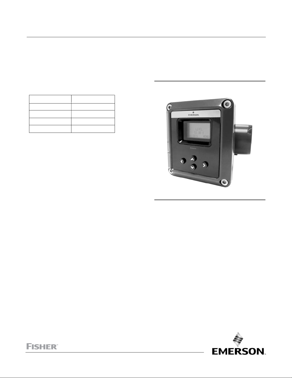
Figure 1. Fisher DLC3100 Digital Level Controller
This manual applies to:
July 2019
Device Type
Device Revision
Hardware Revision
Firmware Revision
DD Revision
130D
1
1
1.0.9
1
Contents
Section 1 Introduction and Specifications 3.........
Scope of Manual 3.............................
Installation , Mounting and Electrical Connections,
and Initial Configuration and Calibration using
the Local User Interface 3....................
Conventions Used 3...........................
Description 3.................................
DLC3100 Digital Level Controller 3...........
249 Caged Sensors 5.......................
249 Cageless Sensors 5.....................
Related Documents 5..........................
Educational Services 8.........................
Section 2 Electrical Connections 13................
Test Connections 13...........................
Alarm Conditions 13...........................
Loop Test 14.................................
Section 3 Overview 15...........................
Status 15....................................
Primary Purpose Variables 15....................
Device Information 15.........................
Section 4 Configuration and Calibration using
AMS Device Manager or a Field Communicator 17...
Configuration Advice 20........................
Force Mode 20............................
Write Protection 20........................
Level Offset 20............................
Initial Setup 21................................
Device Setup 21...........................
PV Setup 23..............................
Process Setup 23..........................
X1456
Manual Setup 24..............................
General 25...............................
Device 25................................
Sensor 26................................
Process 26................................
HART 27.................................
Safety Recovery 27.........................
Alert Setup 28................................
Primary Variable 28........................
Rate Limit 29..............................
Temperature 29...........................
Operational 30............................
Informational 30..........................
Input Compensation 30.....................
Hardware 31..............................
Program and Memory 31...................
Alert Record 31............................
Calibration 32................................
Two Points Calibration 32...................
Min/Max Calibration 33.....................
Weight Calibration 34......................
www.Fisher.com
Page 2

DLC3100 Digital Level Controller
July 2019
Instruction Manual
D104213X012
Two Points Time Delay Calibration 35.........
Zero Trim 36..............................
Gain Trim 36..............................
Torque Rate Gain 36.......................
Accuracy Considerations 37.....................
Effect of Proportional Band 37...............
Density Variations in Interface Applications 37..
Extreme Process Temperatures 38............
Temperature Compensation 38..............
Section 5 Service Tools 39.......................
Active Alerts 39...............................
Tests 40.....................................
Reset/Restore Device 41........................
Section 6 Maintenance and Troubleshooting 42.....
Alert Messages 42.............................
Hardware Diagnostics 43.......................
Removing the DLC3100 from the Sensor 45.......
Front Cover Assembly 48.......................
Removing the Front Cover Assembly 48.......
Replacing the Front Cover Assembly 49.......
Main Electronics Board 49......................
Removing the Main Electronics Board 49......
Replacing the Main Electronics Board 49.......
LCD Assembly 50..............................
Removing the LCD Assembly 50..............
Replacing the LCD Assembly 50..............
Terminal Box Electronics Board 50...............
Removing the Terminal Box
Electronics Board 50.....................
Replacing the Terminal Box
Electronics Board 51.....................
Packing for Shipment 51.......................
Section 7 Parts 52..............................
Parts Ordering 52.............................
Parts Kits 52..................................
Parts List 52..................................
Mounting Kits 56..............................
Sunshade 58.................................
Appendix A Principle of Operation 60..............
HART Communication 60.......................
Multidrop Communication 60...................
Digital Level Controller Operation 61.............
Appendix B Field Communicator Fast-Key
Sequence and Menu Tree 65.....................
2
Page 3

Instruction Manual
D104213X012
DLC3100 Digital Level Controller
July 2019
Section 1
Introduction and Specifications
Scope of Manual
This instruction manual is a supplement to the DLC3100 and DLC3100 SIS Quick Start Guide (D104214X012) that
ships with every digital level controller. This instruction manual includes specifications, operating, and maintenance
information for FIELDVUE DLC3100 and DLC3100 SIS digital level controllers.
Notes
The DLC3100 SIS is identified by a label affixed to the terminal box cover.
Unless otherwise noted, the information in this document applies to both DLC3100 and DLC3100 SIS. However, for simplicity, the
DLC3100 model name will be used throughout.
This instruction manual supports the 475 Field Communicator with device description revision 1, used with DLC3100
instruments with firmware revision 1.0.9. You can obtain information about the process, instrument, or sensor using
the Field Communicator. Contact your Emerson sales office
to obtain the appropriate software.
Do not install, operate, or maintain a DLC3100 digital level controller without being fully trained and qualified in valve,
actuator, and accessory installation, operation, and maintenance. To avoid personal injury or property damage, it is
important to carefully read, understand, and follow all the contents of this manual, including all safety cautions and
warnings. If you have any questions regarding these instructions, contact your Emerson sales office before proceeding.
Installation, Mounting and Electrical Connections, and Initial
Configuration and Calibration using the Local User Interface
Refer to the DLC3100 and DLC3100 SIS Quick Start Guide (D104214X012) for installation and connection information,
as well as initial configuration and calibration using the local user interface. If a copy of this quick start guide is needed
contact your Emerson sales office or visit Fisher.com.
Conventions Used
This manual describes using the Field Communicator to configure and calibrate the digital level controller.
Procedures that require the use of the Field Communicator have the text path and the sequence of numeric keys
required to display the desired Field Communicator menu.
Description
DLC3100 Digital Level Controller
DLC3100 digital level controllers (figure 2) are used with level sensors to measure liquid level, the level of interface
between two liquids, or liquid density. Changes in level or density exert a buoyant force on a displacer, which rotates
the torque tube shaft (see figure 3). This rotary motion is applied to the digital level controller, transformed to an
electrical signal and digitized. The digital signal is compensated and processed per user configuration requirements,
and converted back to a 4-20 mA analog electrical signal. See the block diagram in figure 4.
3
Page 4
DLC3100 Digital Level Controller
July 2019
Instruction Manual
D104213X012
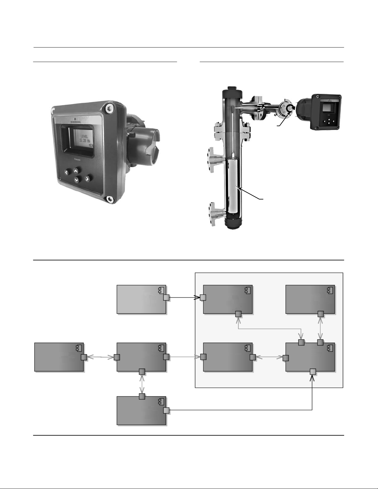
Figure 2. Fisher DLC3100 Digital Level Controller
X1461
Figure 3. Fisher 249 Torque Tube Rotation
TORQUE
TUBE
DISPLACER
X1501
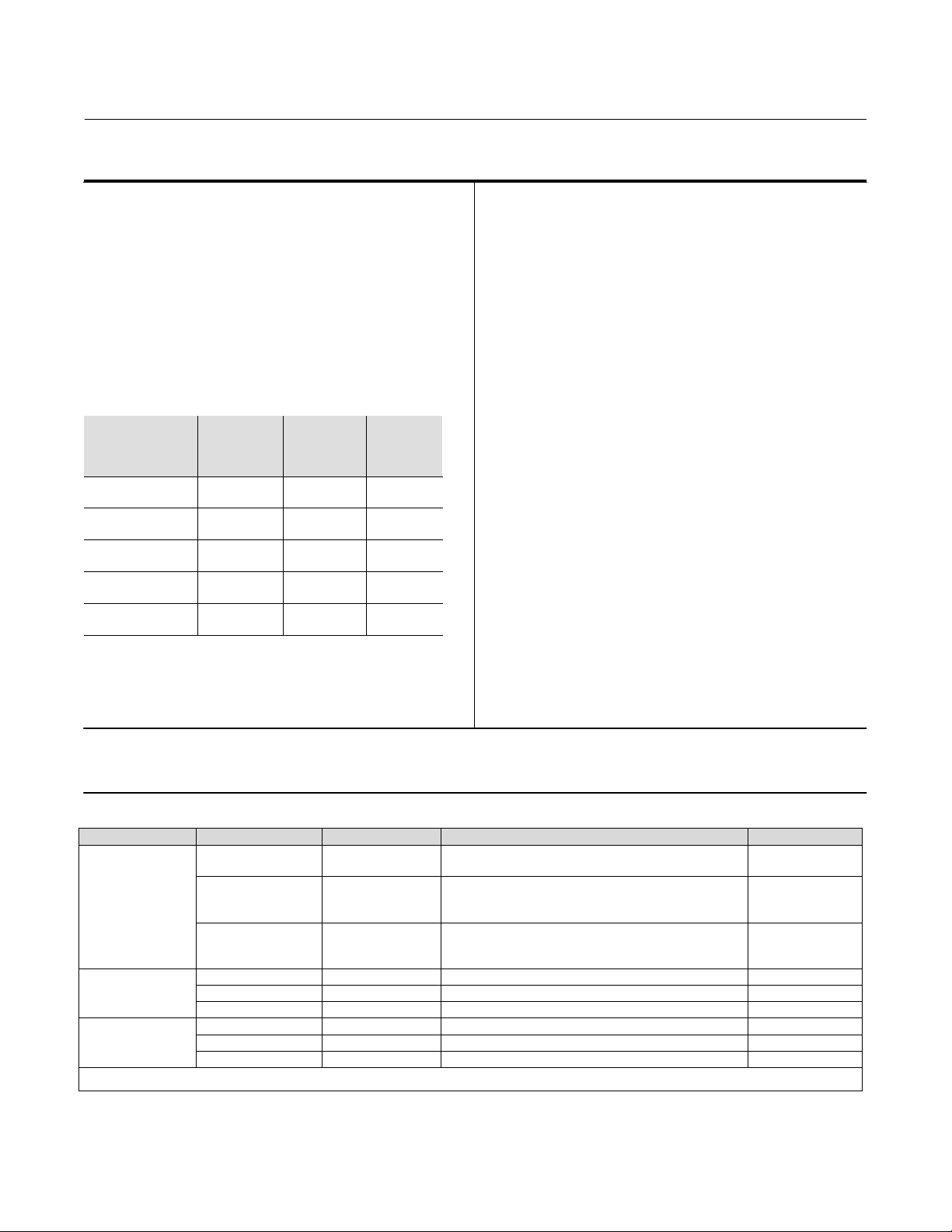
Figure 4. Mechanical Architecture
Mechanical
249 Torque Tube
Mechanical
Push Buttons
(with magnets)
Lever Assembly
Lock Mechanism
(with magnets)
Magnetic
Magnetic
Main Electronic Compartment - Ex 'd' IP66 Enclosure
LCD (with reed
switches)
Electrical
Electrical
Hall Sensor
Terminal
Compartment
(with cover)
Main PCB
Electrical
4
Page 5

Instruction Manual
D104213X012
Several operations with the DLC3100 can be performed using the Field Communicator. The digital level controller can
be configured, calibrated, or tested. Using the HART protocol, information from the field can be integrated into
control systems or be received on a single loop basis.
DLC3100 digital level controllers are designed to directly replace standard pneumatic and electro-pneumatic level
transmitters. DLC3100 digital level controllers mount on a wide variety of caged and cageless 249 level sensors. They
can also be mounted on other manufacturers’ displacer type level sensors with designed mounting kits.
DLC3100 Digital Level Controller
July 2019
CAUTION
There are many magnets used in the DLC3100 (lever assembly, push button, coupling handle). Care must be taken to avoid
having a high powered magnet in close proximity. This could cause permanent damage to the DLC3100. Potential sources
of damaging equipment include, but are not limited to: transformers, DC motors, stacking magnet assemblies.
General Guidelines for use of High Power Magnets:
Use of high power magnets in close proximity to any instrument which is operating a process should be avoided.
Regardless of the instrument model, high power magnets can affect its functionality.
249 Caged Sensors
249, 249B, 249BF, 249C, 249K and 249L sensors side-mount on the vessel with the displacer mounted inside a cage
outside the vessel.
249 Cageless Sensors
249BP, 249CP and 249P sensors top-mount on the vessel with the displacer hanging down into the vessel.
249VS sensor side-mounts on the vessel with the displacer hanging out into the vessel.
249W wafer-style sensor mounts on top of a vessel or on a customer-supplied cages.
Related Documents
Other documents containing information related to the DLC3100 digital level controllers and 249 sensors include:
D FIELDVUE DLC3100 and DLC3100 SIS Quick Start Guide (D104214X012
D CSA (United States and Canada) Hazardous Area Approvals - DLC3100 Digital Level Controller (D104232X012
D ATEX and IECEx Hazardous Area Approvals - DLC3100 Digital Level Controller (D104233X012)
D Fisher 249 Caged Displacer Sensors Instruction Manual (D200099X012
D Fisher 249 Cageless Displacer Sensors Instruction Manual (D200100X012
D Fisher 249VS Cageless Displacer Sensor Instruction Manual (D103288X012
D Fisher 249W Cageless Wafer Style Level Sensor Instruction Manual (D102803X012
)
)
)
)
)
)
D Simulation of Process Conditions for Calibration of Fisher Level Controllers and Transmitters (D103066X012
D Bolt Torque Information (D103220X012
D Bulletin 11.2:DLC3100 - FIELDVUE DLC3100 and DLC3100 SIS Digital Level Controllers (D104216X012
D Bulletin 34.2:249 - Fisher 249 Sensor, Level Controller, and Transmitter Dimensions (D200039X012
These documents are available from your Emerson sales office
)
)
)
or at Fisher.com.
)
5
Page 6

DLC3100 Digital Level Controller
July 2019
Table 1. Fisher DLC3100 Specifications
Instruction Manual
D104213X012
Available Configurations
Mounts on caged and cageless 249 sensors
Function: Transmitter
Communications Protocol: HART
Input Signal
(1)
Level, Interface, or Density
: Rotary motion of
torque tube shaft proportional to changes in liquid
level, interface level, or density that change the
buoyancy of a displacer.
Process Temperature: Interface for 2- or 3-wire
100 ohm platinum RTD for sensing process
temperature, or optional user-entered target
temperature to permit compensating for changes in
specific density.
Output Signal
Analog: 4 to 20 mA DC
J Direct action—increasing level, interface, or density
increases output; or
J Reverse action—increasing level, interface, or
density decreases output
High saturation: 20.5 mA
Low saturation: 3.8 mA
High alarm
Low Alarm
(2)
: > 21.0 mA
(2)
: < 3.6 mA
Digital: HART 1200 Baud Frequency Shift Keyed (FSK)
HART impedance requirements must be met to
enable communication. Total shunt impedance
across the master device connections (excluding the
master and transmitter impedance) must be between
230 and 600 ohms.
The transmitter HART receive impedance is defined
as:
Rx: 30.2 k ohms and
Cx: 5.45 nF
Supply Requirements
Transient Voltage Protection
Pulse Waveform
Rise Time
(ms)
10 1000 48.4 12.4
Decay
to 50% (ms)
Max VCL @ I
(Clamping
Voltage) (V)
pp
I
pp
(Peak Pulse
Current) (A)
Electrical Classification
Overvoltage Category II per IEC 61010 clause 5.4.2d
Pollution Degree 4
Altitude Rating
Up to 2000 meters (6562 feet)
Ambient Temperature
The combined temperature effect on zero and span
without the 249 sensor is less than 0.02% of full scale
per degree Celsius over the operating range -40 to
80_C (-40 to 176_F)
LCD operating temperature limits: -20 to 70_C
(-4 to 158_F)
(3)
Process Temperature
The process density and torque rate are affected by
the process temperature (figure 6). Temperature
compensation can be implemented to correct for
process density changes.
Process Density
The sensitivity to error in knowledge of process
density is proportional to the differential density of
the calibration. If the differential specific gravity is
0.2, and error of 0.02 specific gravity units in
knowledge of a process fluid density represents 10%
of span.
Hazardous Area
CSA
Class/Division: Intrinsically Safe, Explosion-proof
(4)
Division 2, Dust Ignition-proof
Zone: Intrinsically Safe, Flameproof, Type n, Dust by
intrinsic safety and Enclosure
ATEX/IECEx—Flameproof, Intrinsic Safety, Dust by
Intrinsic Safety
,
12 to 30 volts DC; 25 mA
Instrument has reverse polarity protection.
A minimum compliance voltage of 17.75 VDC (due to
HART impedance requirement) is required to
guarantee HART communication.
6
Electrical Housing
IP66, Type 4X
Electrical Connections: Two 1/2-14 NPT internal
conduit connections. Both are at the bottom of
terminal box.
-continued-
Page 7
Instruction Manual
D104213X012
Table 1. Fisher DLC3100 Specifications (continued)
DLC3100 Digital Level Controller
July 2019
Electromagnetic Compatibility
DLC3100 meets EN61326-1:2013
Performance is shown in table 2
DLC3100 SIS meets EN61326-3-2:2008
Performance is shown in table 3
DLC3100 SIS
Safety Instrumented System Classification
SIL2 capable - certified by exida Consulting LLC
Performance
(1)
w/ NPS 3
249W, Using
a 14‐inch
Displacer
$0.8% of
output span
- - - - - -
$0.5% of
output span
- - - - - -
<1.0% of
output span
w/ All Other
249 Sensors
$0.5% of
output span
$0.3% of
output span
<1.0% of
output span
Performance
Criteria
Independent
Linearity
Hysteresis
Repeatability
Dead Band
Hysteresis plus
Deadband
NOTE: At full design span, reference conditions.
1. To lever assembly rotation inputs.
DLC3100
Digital Level
Controller
$0.25% of
output span
<0.2% of
output span
$0.1% of full
scale output
<0.05% of
input span
- - -
At effective proportional band (PB)<100%, linearity,
dead band, and repeatability are derated by the factor
(100%/PB)
Minimum Differential Specific Gravity
0.05 SGU
Construction Material
Housing and Cover: Low-copper aluminum die
casting alloy
Internal: Aluminum, and stainless steel; encapsulated
printed circuit board
Lever assembly: Plated steel, Neodymium iron boron
magnets
Hall Guard: Thermoplastic elastomer
Weight
Less than 3.45 kg (7.57 lb)
Options
J Heat insulator (see figure 5 for use guidelines)
J Sunshade J Mountings for Masoneilan, Yamatake,
Foxboro-Eckhardt sensors
J Factory Calibration:
available for instruments factory-mounted on 249
sensor, when application, process temperature and
density are supplied
1. Density application is not available in DLC3100 SIS.
2. Only one of the High/Low alarm definition is available in a given configuration. Both alarms are NAMUR NE43 compliant.
3. Outside of this limit, LCD will not be readable but it will not affect the functionality of DLC3100 if the temperature is still within the normal limits. Push buttons will be disabled when instrument
temperature is below -20°C (-4°F) or above 70°C (158°F) where LCD display might be intermittent.
4. Not for use in Ester and Ketone atmospheres.
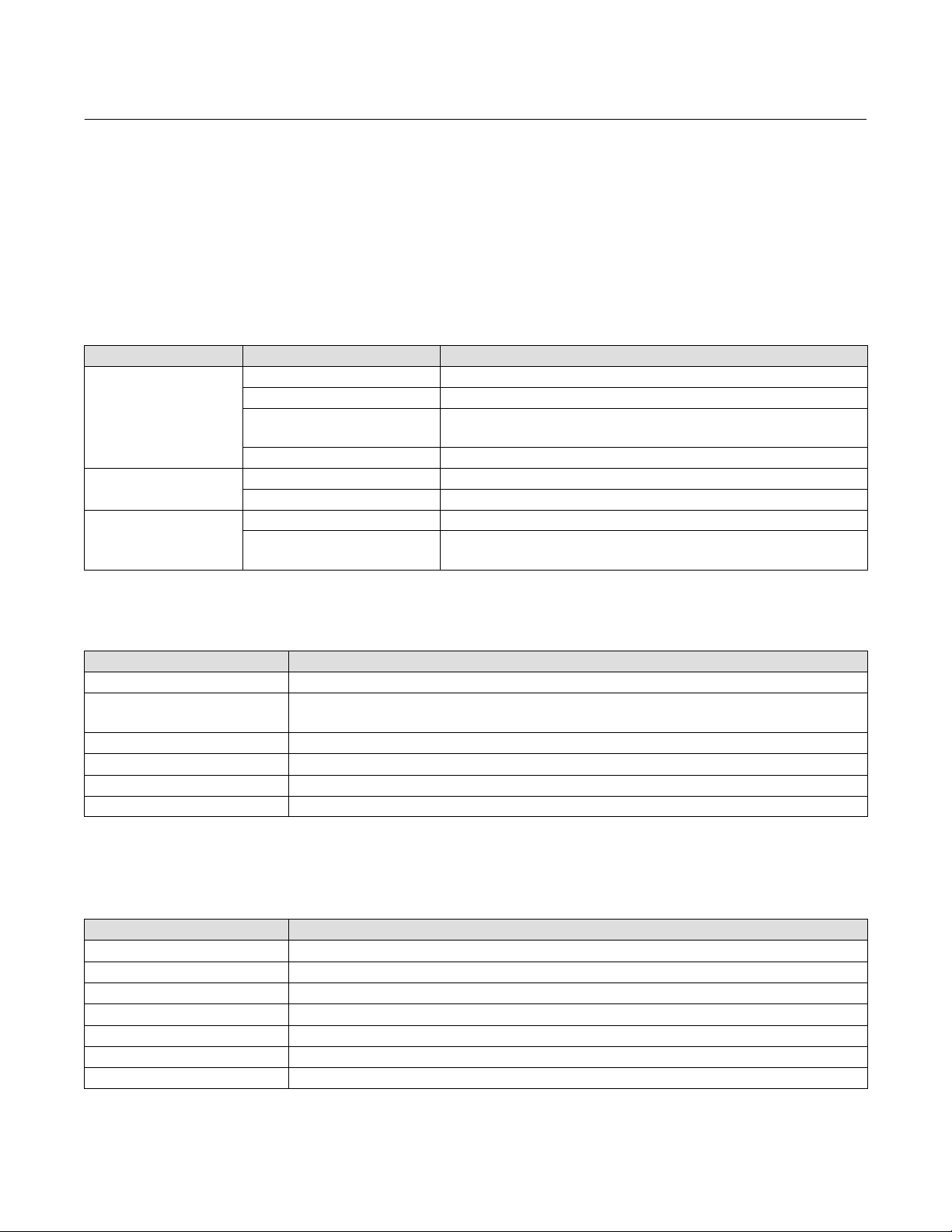
Table 2. DLC3100 EMC Summary Results—Immunity per EN61326-1
Port Phenomenon Basic Standard Test Level Test Results
Electrostatic
discharge (ESD)
Enclosure
I/O signal/control
Protective earth
1. A = No degradation during testing. B = Temporary degradation during testing, but is self‐recovering. Specification limit = +/- 1% of span.
2. HART communication was considered as “not relevant to the process” and is used primarily for configuration, calibration, and diagnostic purposes.
Radiated EM field IEC 61000-4-3
Radiated power
frequency magnetic
field
Burst IEC 61000-4-4 1 kV A
Surge IEC 61000-4-5 1kV (line to ground only, each) B
Conducted RF IEC 61000-4-6 150 kHz to 80 MHz at 3 Vrms A
Burst IEC 61000-4-4 2 kV A
Surge IEC 61000-4-5 2 kV (line to ground only) B
Conducted RF IEC 61000-4-6 150 kHz to 80 MHz at 3 Vrms A
IEC 61000-4-2
80 to 1000 MHz @ 10V/m with 1 kHz AM at 80%
1400 to 2000 MHz @ 3V/m with 1 kHz AM at 80%
2000 to 2700 MHz @ 1V/m with 1 kHz AM at 80%
IEC 61000-4-8 30 A/m at 50 and 60 Hz A
4 kV contact
8 kV air
(1)(2)
A
A
7
Page 8
DLC3100 Digital Level Controller
July 2019
Instruction Manual
D104213X012
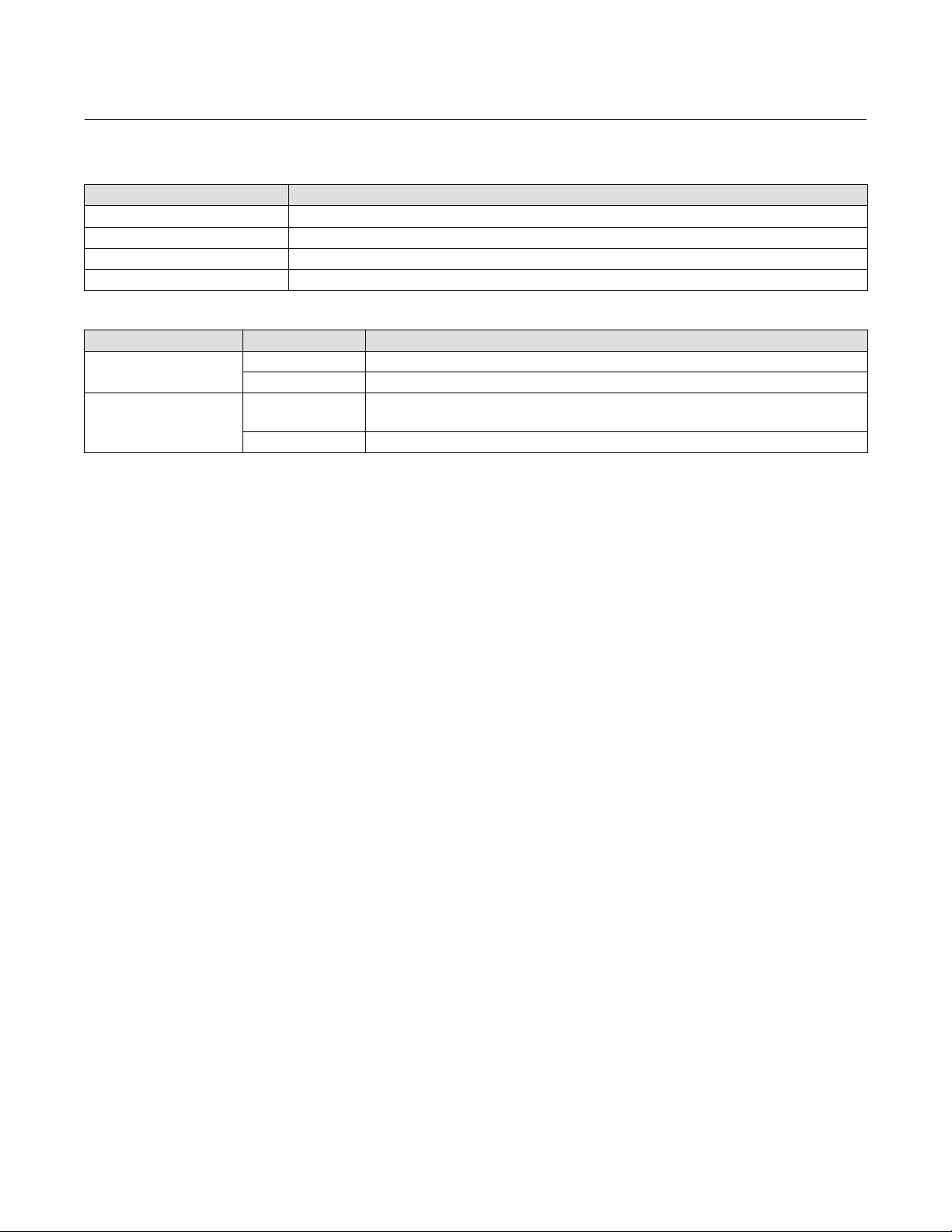
Table 3. DLC3100 SIS EMC Summary Results—Immunity per EN61326-3-2
Port Phenomenon Basic Standard Test Level Test Results
Electrostatic
discharge (ESD)
IEC 61000-4-2
6 kV contact
8 kV air
80 to 1000 MHz @ 10V/m with 1 kHz AM at 80%
Enclosure
Radiated EM field IEC 61000-4-3
1400 to 2000 MHz @ 10V/m with 1 kHz AM at 80%
2000 to 2700 MHz @ 3V/m with 1 kHz AM at 80%
Radiated power
frequency magnetic
IEC 61000-4-8 100 A/m at 50 and 60 Hz A
field
Burst IEC 61000-4-4 1 kV A
I/O signal/control
Surge IEC 61000-4-5 1 kV (line to ground only, each) FS
Conducted RF IEC 61000-4-6 10 kHz to 80 MHz at 10 Vrms A
Burst IEC 61000-4-4 2 kV A
Protective earth
Surge IEC 61000-4-5 1 kV (line to ground only) A
Conducted RF IEC 61000-4-6 10 kHz to 80 MHz at 10 Vrms A
1. A = No degradation during testing. B = Temporary degradation during testing, but is self‐recovering. FS = Fail Safe. Specification limit = +/- 2% of span.
2. HART communication was considered as “not relevant to the process” and is used primarily for configuration, calibration, and diagnostic purposes.
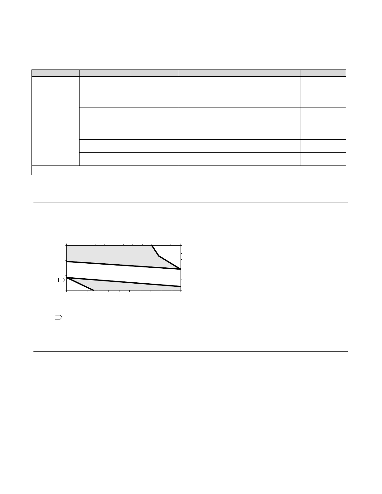
Figure 5. Guidelines for Use of Optional Heat Insulator Assembly
-40 -30
800
-20 -10
010 20
30 40 50 60
AMBIENT TEMPERATURE (_C)
HEAT INSULATOR
400
0
1
TOO
COLD
-325
PROCESS TEMPERATURE (_F)
0 20 40 60 80 100 120 140 160
-20-40
REQUIRED
NO HEAT INSULATOR NECESSARY
HEAT INSULATOR
REQUIRED
AMBIENT TEMPERATURE (_F)
STANDARD TRANSMITTER
NOTES:
1 FOR PROCESS TEMPERATURES BELOW -29_C (-20_F) AND ABOVE 204_C (400_F)
SENSOR MATERIALS MUST BE APPROPRIATE FOR THE PROCESS; SEE TABLE 5.
2. IF AMBIENT DEW POINT IS ABOVE PROCESS TEMPERATURE, ICE FORMATION MIGHT
CAUSE INSTRUMENT MALFUNCTION AND REDUCE INSULATOR EFFECTIVENESS.
39A4070‐B
A5494‐1
TOO
HOT
70
80
425
400
300
200
100
0
-100
-200
176
PROCESS TEMPERATURE (_C)
(1)(2)
A
A
Educational Services
For information on available courses contact:
Emerson Automation Solutions
Educational Services, Registration
Phone: +1-641-754-3771 or +1-800-338-8158
e‐mail: education@emerson.com
emerson.com/fishervalvetraining
8
Page 9
Instruction Manual
DLC3100 Digital Level Controller
D104213X012
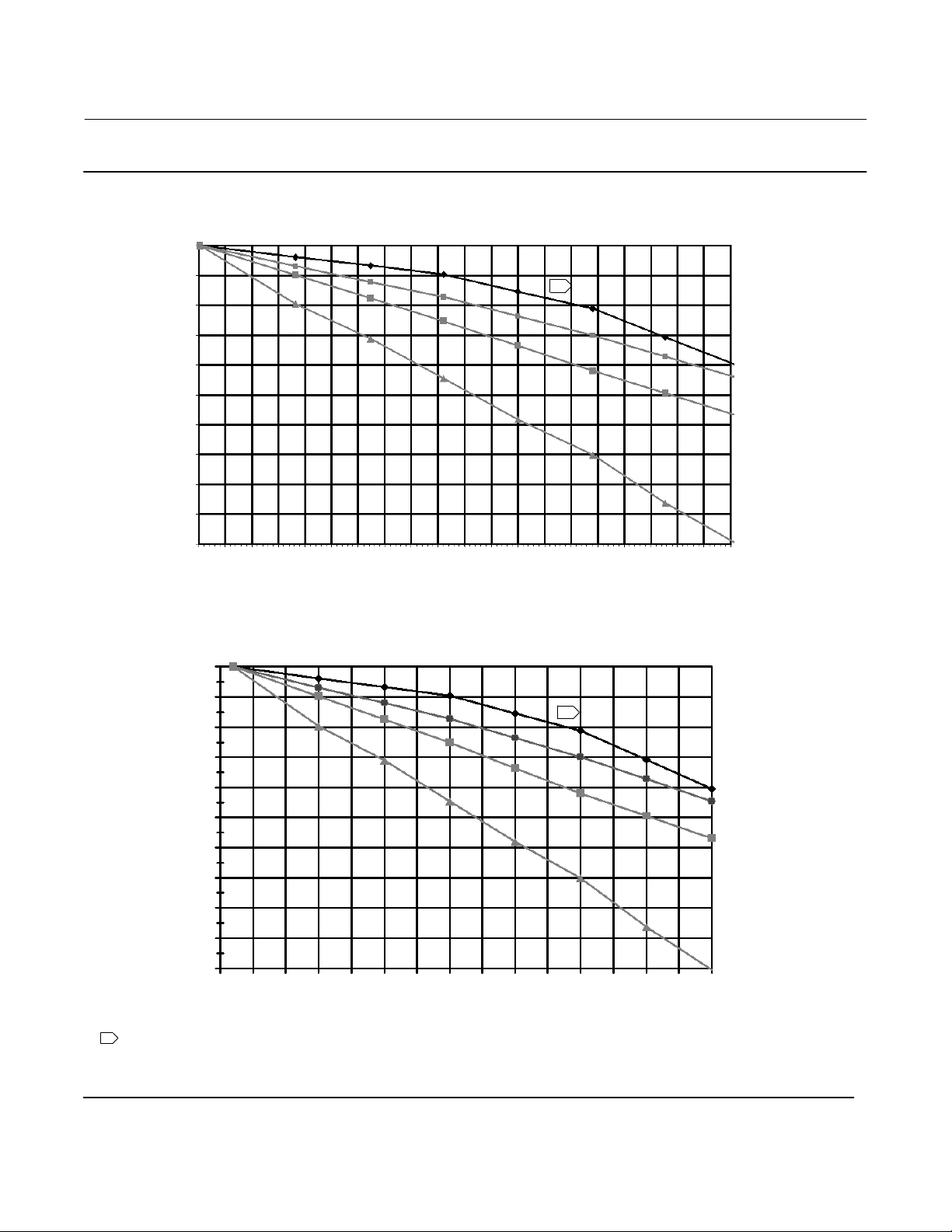
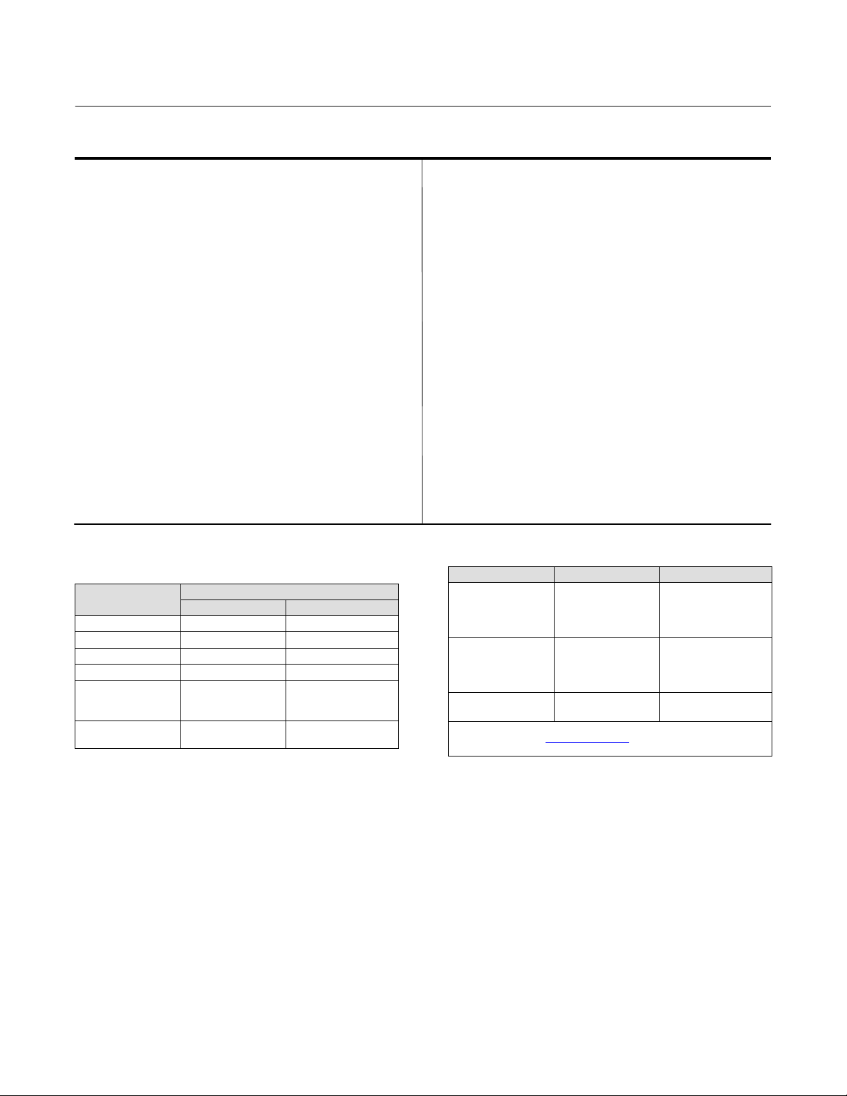
Figure 6. Theoretical Reversible Temperature Effect on Common Torque Tube Materials
TORQUE RATE REDUCTION
(NORMALIZED MODULUS OF RIGIDITY)
1.00
July 2019
0.98
0.96
0.94
0.92
0.90
norm
G
0.88
0.86
0.84
0.82
0.80
20 40 60 80 100 120 140 160 180 200 220 240 260 280 300 320 340 360 380 400 420
1
TEMPERATURE (_C)
TORQUE RATE REDUCTION
(NORMALIZED MODULUS OF RIGIDITY)
1.00
0.98
0.96
1
N05500
N06600
N10276
S31600
0.94
0.92
norm
0.90
G
0.88
0.86
0.84
0.82
0.80
50 100 150 200 250 300 350 400 450 500 550 600 650 700 750 800
TEMPERATURE (_F)
NOTE:
1 DUE TO THE PERMANENT DRIFT THAT OCCURS NEAR AND ABOVE 260_C (500_F), N05500 IS NOT
RECOMMENDED FOR TEMPERATURES ABOVE 232_C (450_F).
N05500
N06600
N10276
S31600
9
Page 10
DLC3100 Digital Level Controller
July 2019
Table 4. Fisher 249 Sensor Specifications
Input Signal
Liquid Level or Liquid‐to‐Liquid Interface Level:
From 0 to 100 percent of displacer length
Liquid Density: From 0 to 100 percent of
displacement force change obtained with given
displacer volume—standard volumes are
J980 cm
or
J1640 cm
3
(60 inches3) for 249C and 249CP sensors
3
(100 inches3) for most other sensors;
other volumes available depending upon sensor
construction
Sensor Displacer Lengths
See tables 7 and 8 footnotes
Sensor Working Pressures
Consistent with applicable ANSI
pressure/temperature ratings for the specific sensor
constructions shown in tables 7 and 8
Caged Sensor Connection Styles
Cages can be furnished in a variety of end connection
styles to facilitate mounting on vessels; the
Instruction Manual
D104213X012
equalizing connection styles are numbered and are
shown in figure 7.
Mounting Positions
Most level sensors with cage displacers have a
rotatable head. The head may be rotated through
360 degrees to any of eight different positions.
Construction Materials
See tables 6, 7, and 8
Operative Ambient Temperature
See table 5
For ambient temperature ranges, guidelines, and use
of optional heat insulator see figure 5
Options
J Heat insulator J Gauge glass for pressures to
29 bar at 232_C (420 psig at 450_F), and
gauges for high temperature and pressure
applications
J Reflex
Table 5. Allowable Process Temperatures for
Common 249 Sensor Pressure Boundary Materials
MATERIAL
Cast Iron -29_C (-20_F) 232_C (450_F)
Steel -29_C (-20_F) 427_C (800_F)
Stainless Steel -198_C (-325_F) 427_C (800_F)
N04400 -198_C (-325_F) 427_C (800_F)
Graphite
Laminate/SST
Gaskets
N04400/PTFE
Gaskets
-198_C (-325_F) 427_C (800_F)
-73_C (-100_F) 204_C (400_F)
PROCESS TEMPERATURE
Min. Max.
Table 6. Displacer and Torque Tube Materials
Part Standard Material Other Materials
316 Stainless Steel,
Displacer 304 Stainless Steel
Displacer Stem
Driver Bearing,
Displacer Rod and
Driver
Torque Tube N05500
1. N05500 is not recommended for spring applications above 232_C
(450_F). Contact your Emerson sales office
temperatures exceeding this limit are required.
316 Stainless Steel
(1)
N10276, N04400,
Plastic, and Special
Alloys
N10276, N04400,
other Austenitic
Stainless Steels, and
Special Alloys
316 Stainless Steel,
N06600, N10276
or application engineer if
10
Page 11
Instruction Manual
D104213X012
DLC3100 Digital Level Controller
July 2019
Table 7. Caged Displacer Sensors
TORQUE TUBE
ORIENTATION
249
SENSOR
(3)
(1)
STANDARD CAGE, HEAD,
AND TORQUE TUBE ARM
MATERIAL
Cast iron
EQUALIZING CONNECTION
Style Size (NPS)
Screwed 1‐1/2 or 2
Flanged 2
Screwed or optional socket weld 1‐1/2 or 2 CL600
1‐1/2
2
1‐1/2
Torque tube
arm rotatable
with respect to
equalizing
connections
249B, 249BF
(3)
249C
(4)
Steel
316 stainless steel
Raised face or optional ring‐type joint
flanged
Screwed 1‐1/2 or 2 CL600
Raised face flanged
2
249K Steel
249L Steel Ring‐type joint flanged 2
1. Standard displacer lengths for all styles (except 249) are 14, 32, 48, 60, 72, 84, 96, 108 and 120 inches. The 249 uses a displacer with a length of either 14 or 32 inches.
2. EN flange connections available in EMA (Europe, Middle East and Africa).
3. Not available in EMA.
4. The 249BF available in EMA only. Also available in EN size DN 40 with PN 10 to PN 100 flanges and size DN 50 with PN 10 to PN 63 flanges.
5. Top connection is NPS 1 ring‐type joint flanged for connection styles F1 and F2.
Table 8. Cageless Displacer Sensors
Mounting Sensor
(1)
Standard Head
(6)
Body
and Torque Tube
(2),
Wafer
Raised face or optional ring‐type joint
flanged
1‐1/2 or 2 CL900 or CL1500
(5)
Flange Connection (Size) Pressure Rating
Arm Material
NPS 4 raised face or optional ring‐type joint CL150, CL300, or CL600
NPS 6 or 8 raised face CL150 or CL300
NPS 4 raised face or optional ring‐type joint
NPS 6 or 8 raised face
CL900 or 1CL500
(EN PN 10 to DIN PN 250)
CL150, CL300, CL600, CL900,
CL1500, or CL2500
CL125, CL150, CL250, CL300,
For NPS 4 raised face or flat face
CL600, CL900, or CL1500
(EN PN 10 to DIN PN 160)
Mounts on
top of vessel
Mounts on
side of vessel
(4)
249BP
Steel
249CP 316 Stainless Steel NPS 3 raised face CL150, CL300, or CL600
(5)
249P
Steel or stainless steel
WCC (steel) LCC (steel), or
249VS
CF8M (316 stainless steel)
WCC, LCC, or CF8M For NPS 4 buttweld end, XXZ CL2500
Mounts on top of
vessel or on
customer
249W
supplied cage
1. Standard displacer lengths are 14, 32, 48, 60, 72, 84, 96, 108, and 120 inches.
2. Not used with side‐mounted sensors.
3. EN flange connections available in EMA (Europe, Middle East and Africa).
4. Not available in EMA.
5. 249P available in EMA only.
6. Wafer Body only applicable to the 249W.
WCC or CF8M For NPS 3 raised face CL150, CL300, or CL600
LCC or CF8M For NPS 4 raised face CL150, CL300, or CL600
PRESSURE RATING
CL125 or CL250
CL150, CL300, or
CL600
CL150, CL300, or
CL600
CL150, CL300, or
CL600
CL150, CL300, or
CL600
CL2500
(3)
(2)
11
Page 12
DLC3100 Digital Level Controller
July 2019
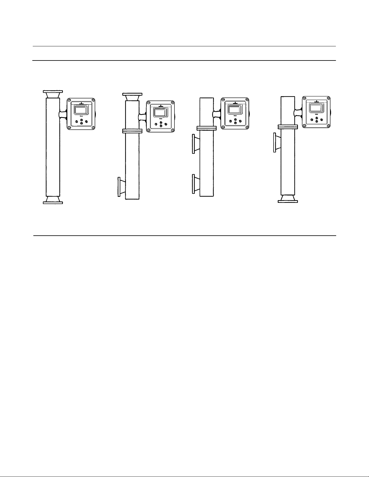
Figure 7. Style Number of Equalizing Connections
Instruction Manual
D104213X012
STYLE 1
TOP & BOTTOM
CONNECTIONS
SCREWED (S-1) OR
FLANGED (F-1)
E1697
STYLE 2 STYLE 3 STYLE 4
TOP & LOWER SIDE
CONNECTIONS
SCREWED (S-2) OR
FLANGED (F-2)
UPPER & LOWER SIDE
CONNECTIONS
SCREWED (S-3) OR
FLANGED (F-3)
UPPER SIDE & BOTTOM
SCREWED (S-4) OR
CONNECTIONS
FLANGED (F-4)
12
Page 13

Instruction Manual
D104213X012
DLC3100 Digital Level Controller
July 2019
Section 2
Electrical Connections
Note
This information supplements the Electrical Connections section in the quick start guide (D104214X012
instrument. If a copy of this quick start guide is needed contact your Emerson sales office
or visit Fisher.com.
Test Connections
WARNING
Personal injury or property damage caused by fire or explosion may occur if this connection is attempted in an area which
contains a potentially explosive atmosphere or has been classified as hazardous. Confirm that area classification and
atmosphere conditions permit the safe removal of the terminal box cap before proceeding.
) that shipped with your
Test connections inside the terminal box can be used to measure loop current across an internal 1 ohm resistor.
1. Remove the terminal box cap.
2. Adjust the test meter to measure mV.
3. Connect the positive lead of the test meter to the + connection and the negative lead to the TEST connection inside
the terminal box.
4. Measure Loop current as mV = mA. For example, if the meter measures 12.5 mV, it means the loop current is
12.5 mA.
5. Remove test leads and replace the terminal box cover.
Alarm Conditions
Each digital level controller continuously monitors its own performance during normal operation. This automatic
diagnostic routine is a timed series of checks repeated continuously. If diagnostics detect a failure in the electronics,
the instrument drives its output to trip alarm current either below 3.6 mA or above 21 mA, depending on the position
(High/Low) of the alarm switch.
An alarm condition occurs when the self-diagnostics detect an error that would render the process variable
measurement inaccurate, incorrect, or undefined, or a user defined threshold is violated. At this point the analog
output of the unit is driven to a defined level either above or below the nominal 4-20 mA range, based on the position
of the alarm switch. The factory default Alarm Switch setting is High.
Refer to table 9 for alerts that will trigger the Trip Alarm Current when enabled.
13
Page 14
DLC3100 Digital Level Controller
July 2019
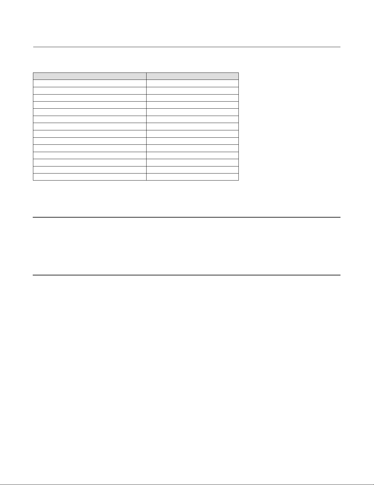
Table 9. Trip Alarm Current Default Setting
Alerts Trip Alarm Current Default Setting
Device Malfunction Enable
Reference Voltage Failed Enable
PV Analog Output Readback Limit Failed Enable
Instrument Temperature Sensor Alert Enable
Hall Sensor Alert Enable
RTD Sensor Alert Enable
Hall Diagnostic Failed Enable
RTD Diagnostic Failed Enable
Program Memory Failed Enable
NVM Error Enable
RAM Test Error Alert Enable
Watchdog Reset Executed Enable
PV HiHi Alert Disable
PV LoLo Alert Disable
Loop Test
Instruction Manual
D104213X012
Note
The DLC3100 must be put out of service during Loop Test. Place the loop into manual operation before putting device out of
service as the DLC3100 output may not be valid.
When the DLC3100 is out of service, it is locked for exclusive access by the Primary/Secondary master that put it out of service. If
the instrument reports Locked by HART or Access Restricted when you attempt to configure it, and a master of the original
priority is not available, use Force Mode on the Local User Interface menu to force the instrument mode to In Service. You will
then be able to take it out of service with your own master to make changes.
Loop Test can be used to verify the controller output, the integrity of the loop, and the operations of any recorders or
similar devices installed in the loop. To initiate a loop test, perform the following procedure:
1. Connect a reference meter to the controller. To do so, either connect the meter to the test connections inside the
terminal box (see Test Connections procedure) or connect the meter in the loop as shown in figure 8.
2. Access Loop Test via Service Tools > Maintenance > Tests > Loop Test (3-4-2-2).
3. Select OK after you set the control loop to manual. The Field Communicator displays the loop test menu.
4. Put the instrument to “Not in Service” and select analog output level: 4mA, 20mA or Other to manually input a
value between 4 and 20 milliamps.
5. Check the reference meter to verify that it reads the value that is commanded. If the readings do not match, either
the controller requires an output trim, or the meter is malfunctioning.
After completing the test procedure, the display returns to the loop test screen and allows you to choose another
output value or end the test and put instrument back in service.
14
Page 15
Instruction Manual
D104213X012
DLC3100 Digital Level Controller
July 2019
Section 3
Overview
Overview provides information about the current state of the instrument, measurement data, and device variables
that are of interest.
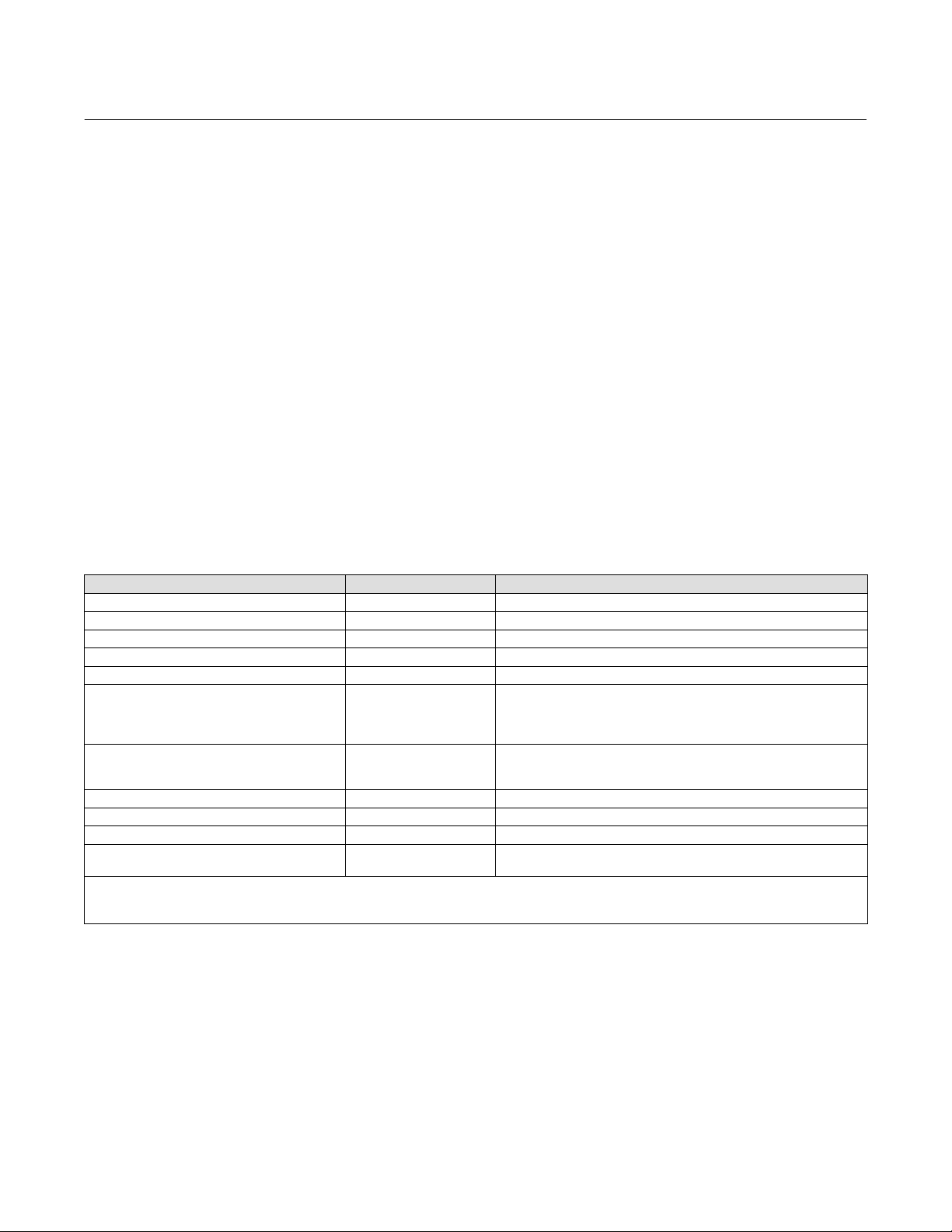
Status
Name Status Description
Device
Communications
Mode
Good
Failure
Maintenance
Advisory
Polled
Simulation Active
In Service
Not In Service
There are no active alerts and instrument is In Service.
The highest severity active alert is in the Failure category.
The highest severity active alert is in the Maintenance
category.
The highest severity active alert is in the Advisory category.
Communication with digital level controller is established.
Digital level controller is in alert simulation mode.
Digital level controller is online and performing its function.
Digital level controller is Out of Service. Output may not be
valid.
Primary Purpose Variables
Name Description
Process Fluid Name of the process fluid.
Process Fluid Compensated
Density
PV Actual measurement in percentage of span.
PV Value Actual measurement in unit.
Process Temperature Actual temperature of the process (via RTD or manual input).
Analog Output Current output of the digital level controller, in milliamps.
Density of the process fluid. If temperature compensation is enabled, the density
value is after compensation.
Device Information
Identification
Name Description
Tag A unique name to identify the HART device, up to 8 characters.
Long Tag A unique name to identify the HART device, up to 32 characters.
Model Field device model: DLC3100
Device ID The ID of the printed wiring board in the instrument.
Instrument Serial Number Serial number printed on the nameplate of the device.
Sensor Serial Number Serial number printed on the nameplate of the 249 sensor.
Instrument Assembly Code Unique code in device for traceability.
15
Page 16
DLC3100 Digital Level Controller
July 2019
Instruction Manual
D104213X012
Revisions
Name Description
HART Universal Revision The revision number of the HART Universal Commands used by the instrument.
Device Revision The revision number of the instrument-to-HART communicator interface software.
Hardware The revision number of the instrument hardware.
Firmware The revision number of the instrument firmware.
Alarm Type and Security
Name Value Description
Alarm Switch
Protection
High Analog output will be >= 21mA when Trip Alarm Current is activated.
Low Analog output will be <= 3.6mA when Trip Alarm Current is activated.
Enable
When protection is enabled, writing to parameters and calibration are
not allowed.
Disable When protection is disabled, device can be configured and calibrated.
16
Page 17

Instruction Manual
D104213X012
DLC3100 Digital Level Controller
Section 4
Configuration and Calibration using AMS Device Manager or a
Field Communicator
Note
Refer to the DLC3100 and DLC3100 SIS Quick Start Guide (D104214X012
interface. If a copy of this quick start guide is needed contact your Emerson sales office
DLC3100 has to be set to “Not In Service” during configuration and calibration which include:
D Device Setup
D PV Setup
D Process Setup
D Calibration
D Manual Setup
D Alert Setup
) for configuration and calibration using the local user
or visit Fisher.com.
July 2019
The DLC3100 will continue to regulate the current output based on lever assembly position. The output can be at
failed current value (determine by alarm switch on the Main Electronics Board) depending on the device alerts/status.
This current output shall not be treated as actual level/interface measurement as the device is “Not In Service”.
CAUTION
The control loop must be in manual before putting DLC3100 to Not In Service.
Note
When configuring the DLC3100 using the DD, the access of DLC3100 via Local User Interface will be locked.
If a DLC3100 digital level controller ships from factory mounted on a 249 sensor, initial setup and calibration may not
be necessary. The factory enters the sensor data, couples the instrument to the sensor, and calibrates the instrument
and sensor combination.
17
Page 18
DLC3100 Digital Level Controller
July 2019
Instruction Manual
D104213X012
Note
If the digital level controller mounted on the sensor is received with the displacer blocked, or if the displacer is not connected, the
instrument will be coupled to the torque tube assembly and the lever assembly unlocked. To place the unit in service, if the
displacer is blocked, remove the rod and block at each end of the displacer and check the instrument calibration. (If the “factory
cal” option was ordered, the instrument will be pre-compensated to the process conditions provided on the requisition, and may
not appear to be calibrated if checked against room temperature with 0% and 100% water level inputs). If the displacer is not
connected, hang the displacer on the torque tube.
If the digital level controller mounted on the torque tube arm and the displacer is not blocked when received (such as in skid
mounted systems), the instrument will not be coupled to the torque tube assembly, and the lever assembly will be locked. To
place the unit in service, couple the instrument to the sensor and unlock the lever assembly.
When the 249 assembly is properly connected and coupled to the digital level controller, establish the zero process condition and
perform the Trim Zero procedure. The torque tube rate should not need to be recalibrated.
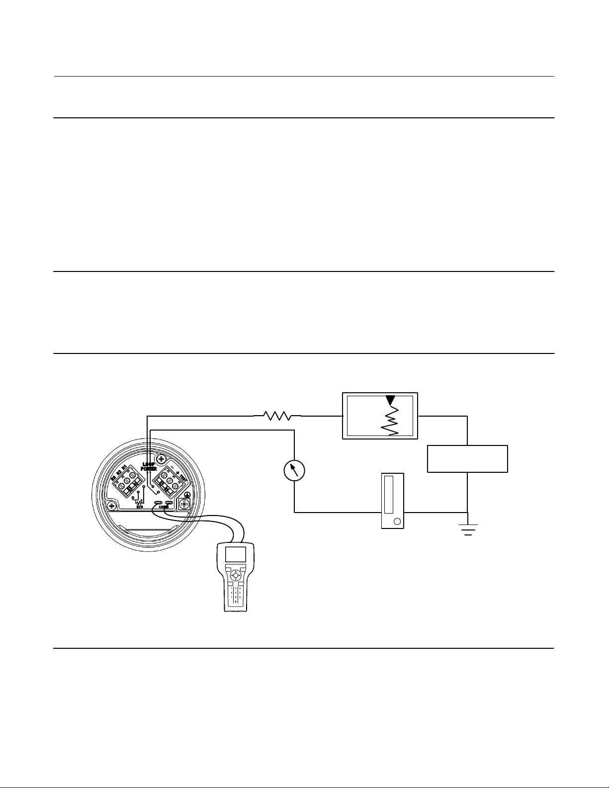
To review the configuration data entered by the factory, connect the instrument to a 24 VDC power supply as shown in
figure 8. Connect the AMS Device Manager/Field Communicator to the instrument and turn it on. Go to Configure and
review the data under Manual Setup and Alert Setup. If application data has been changed since the instrument was
factory-configured, refer to the Manual Setup section for instructions on modifying configuration data.
Figure 8. Connecting to a Power Supply
Field Communicator may be
connected at any termination
point in the signal loop other
than across the power supply.
Signal loop must have between
230 and 600 ohms load for
communication.
230 RL 600
−
Reference meter
+
for calibration
or monitoring
operation. May
be a voltmeter
across 250 ohm
−
resistor or a
current meter.
+
+
Signal loop may be grounded at
any point or left ungrounded.
−
+
POWER
SUPPLY
−
18
Page 19
Instruction Manual
D104213X012
DLC3100 Digital Level Controller
July 2019
For instruments not mounted on a level sensor or when replacing an instrument, initial setup consists of entering
sensor information.
Sensor information includes displacer and torque tube information, such as:
D Displacer Information (Length, Volume and Weight)
D Driver Rod Length
D Mounting position (Left or Right of Displacer)
D Torque Tube Material
D Torque Tube Wall
D Measurement Application (Level, Interface or Density)
D Direct/Reverse Action
D Temperature Compensation (Enable/Disable)
D Process Fluid Density
Refer to table 10 for information required to setup the DLC3100. Most of the information is available from the sensor
nameplate. The moment arm is the effective length of the driver rod length, and depends upon the sensor type. For a
249 sensor, refer to table 11 to determine driver rod (moment arm) length.
Table 10. Setup Information
Description Value Units Available in LUI
Displacer Length mm, cm, m, in, ft
Displacer Volume mm3, cm3, L, in
Displacer Weight G, kg, oz, lb
Driver Rod (Moment Arm) Length mm, cm, m, in, ft
Mounting Right of displacer, Left of displacer
249 Cast, 249A, 249B/249BF, 249BP, 249C, 249CP, 249K, 249L, 249N,
249 Sensor
Torque Tube Material
Torque Tube Wall Thin, Standard, Heavy, Unknown
Measurement Application Level, Interface, Density
Analog Output Action Direct, Reverse
Fluid Density
2. When setting up the density in Degrees Baume, note of the range supported:
Degrees Baume Heavy - 0 degree to 37.6 degree
Degrees Baume Light - 10 degree to 100 degree
Degrees API - 0 degree to 100 degree
249P (CL150-600), 249P (CL900-2500), 249PT, 249V, 249VS, 249VT
(TeeMount), 249VT (SideMount), 249W, 259, Other, Masoneilan,
Foxboro-Eckardt, Yamatake Honeywell, Unknown
K-Monel, Inconel, 316SST, Hasteloy C, DuraNickel, Monel, Alloy 20,
Incoloy, Hasteloy B2, 304SST, 304L SST, 316L SST, 321SST, 347SST,
Custom
SGU, g/cm3, g/mL, g/L, kg/m3, lb/in3, lb/ft3, lb/gal,
Degrees Baume – Heavy, Degrees Baume – Light, Degrees API
3
(2)
19
Page 20
DLC3100 Digital Level Controller
July 2019
Instruction Manual
D104213X012
Configuration Advice
Force Mode
Local User Interface Menu > Force Mode
When the DLC3100 is out of service, it is locked for exclusive access by the Primary/Secondary master that put it out of
service. The same master must be used to put the instrument back in service; another master will not be able to
change anything on the device and the LCD will return a “Locked by HART” message, unless you run Force Mode.
Select Force Mode to force the instrument mode to In Service if the original master is not available.
Note
Make sure no outstanding tasks are on-going in the device, including configuration and calibration, before forcing the DLC3100 In
Service
Write Protection
To setup and calibrate the instrument, write protection must be set to disable.
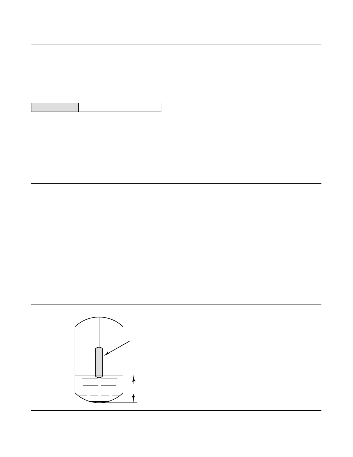
Level Offset
Level Offset is the value DLC3100 reports when the process level is at the bottom of the displacer. Adding a level offset
permits the process variable value in engineering units to be reported with respect to a reference point other than the
bottom of the displacer. Examples include: bottom of the process vessel, the process set point, or sea level. Set Level
Offset is only available in Level or Interface measurement mode. Follow the prompts on the Field Communicator to
enter the offset value (2-3-2-1-6).
Level Offset will affect URV/LRV, PV Hi/Lo, PV HiHi/LoLo alerts. Changing PV alert points assumes you have already
considered the affect of Level Offset on the alert points. This parameter should be cleared to zero before running
Device Setup.
Figure 81. Example of the Use of Level Offset
URV
(10 FEET)
LRV
(6 FEET)
E0368
DISPLACER
LEVEL
OFFSET
(6 FEET)
20
Page 21

Instruction Manual
D104213X012
DLC3100 Digital Level Controller
July 2019
Initial Setup
Initial Setup consists of the following:
D Device Setup
D PV Setup
D Process Setup
All three setup procedures must be completed when configuring the DLC3100 in order for the device to function
properly.
Initial Setup directs you through initialization of configuration data needed for proper operation. When the instrument
comes out of the box, the default dimensions are set for the most common Fisher 249 construction. If any data is
unknown, it is generally safe to accept the defaults. The mounting position - left or right of displacer - is important for
correct interpretation of positive motion. Use Manual Setup to locate and modify individual parameters when they
need to be changed. Refer to the Initial Setup section below for DLC3100 configuration.
Notes
The DLC3100 has to be “Not In Service” when carrying out Initial Setup. Place the loop into manual operation before putting
device out of service as the output will not be valid.
When the DLC3100 is out of service, it is locked for exclusive access by the Primary/Secondary master that put it out of service. If
the instrument reports Locked by HART or Access Restricted when you attempt to configure it, and a master of the original
priority is not available, use Force Mode on the Local User Interface menu to force the instrument mode to In Service. You will
then be able to take it out of service with your own master to make changes.
Guided setup is available to aid initial setup. Follow the prompts to enter information required by the setup. Most of
the information is available from the sensor nameplate.
Device Setup
AMS Configure > Guided Setup > Device Setup
Field Communicator Configure > Guided Setup > Device Setup (2-2-1)
Input the required information as follows:
D Displacer Information (Length, Weight and Volume)
D Driver Rod Length (refer to table 11 and figure 9)
D Mounting Position (Left or Right of Displacer)
D 249 Sensor Model
D Torque Tube Material and wall thickness
The Driver Rod (moment arm) is the effective length of the driver rod length, and depends upon the sensor type. For a
249 sensor, refer to table 11 to determine driver rod length.
Once Device Setup is completed, configure the application settings using the PV Setup procedures.
21
Page 22
DLC3100 Digital Level Controller
July 2019
Instruction Manual
D104213X012
Table 11. Driver Rod Length
SENSOR TYPE
249 203 8.01
249B 203 8.01
249BF 203 8.01
249BP 203 8.01
249C 169 6.64
249CP 169 6.64
249K 267 10.5
249L 229 9.01
249N 267 10.5
249P
(CL125-CL600)
249P
(CL900-CL2500)
249VS (Special)
249VS (Std) 343 13.5
249W 203 8.01
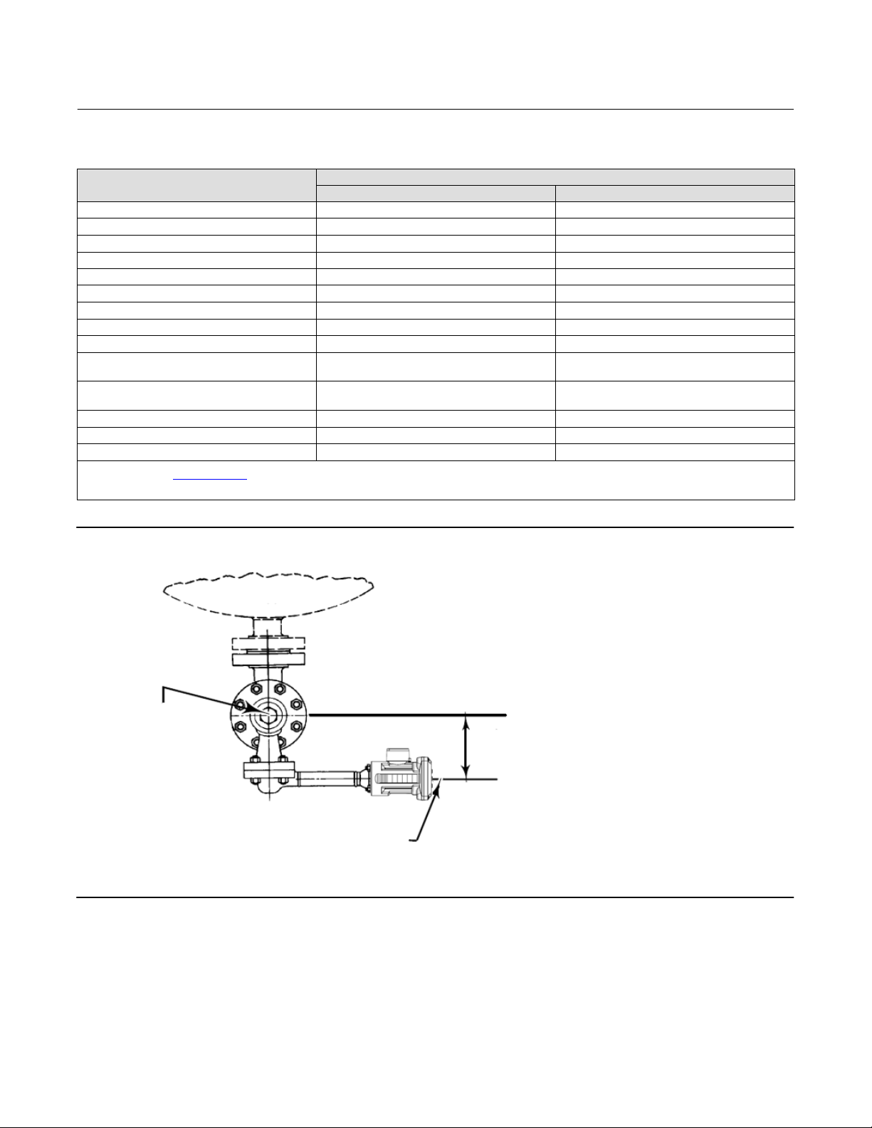
1. Driver rod length is the perpendicular distance between the vertical centerline of the displacer and the horizontal centerline of the torque tube. See figure 9. If you cannot determine the driver
rod length, contact your Emerson sales office
2. This table applies to sensors with vertical displacers only. For sensor types not listed, or sensors with horizontal displacers, contact your Emerson sales office for the driver rod length. For other
manufacturers' sensors, see the installation instructions for that mounting.
(1)
(2)
(1)
and provide the serial number of the sensor.
MOMENT ARM
mm Inch
203 8.01
229 9.01
See serial card See serial card
Figure 9. Method of Determining Moment Arm from External Measurements
VERTICAL C
DISPLACER
VESSEL
OF
L
MOMENT
ARM LENGTH
HORIZONTAL C
TORQUE TUBE
OF
L
22
Page 23
Instruction Manual
D104213X012
DLC3100 Digital Level Controller
PV Setup
AMS Configure > Guided Setup > PV Setup
Field Communicator Configure > Guided Setup > PV Setup (2-2-2)
PV Setup consists of the following:
D Measurement Application (Level, Interface or Density) (see table 12)
D Analog Output Action (Direct or Reverse)
D Level Offset
D Measurement Range (Lower Range Value and Upper Range Value)
Note
For interface applications, if the 249 is not installed on a vessel, or if the cage can be isolated, calibrate the instrument with
weights, water, or other standard test fluid, in level mode. After calibrating in level mode, the instrument can be switched to
interface mode, then enter the actual process fluid specific gravity and range values, follow with Trim Zero.
July 2019
Table 12. Application Information
Measurement Application Description
The default process variable units are set to the same units chosen for displacer length. When level
Level, Interface
Density
offset is changed, range values will be initialized based on level offset and displacer length. The default
upper range value is set to equal to displacer length and the default lower range value is set to zero when
the level offset is 0.
The default process variable units are set to “SGU” (Specific Gravity Units). The default upper range value
is set to “1.0” and the default lower range value is set to ”0.1”.
When a DLC3100 with analog output is set for direct action the loop current will increase as the fluid level increases.
Upper Range Value is the process variable values at 20 mA and Lower Range Value is the process variable values at
4 mA.
Choosing Reverse action will swap the default values of the upper and lower range values. The loop current will
decrease as the fluid level increases. Upper Range Value is the process variable values at 4 mA and Lower Range Value
is the process variable values at 20 mA.
Once PV Setup is completed configure the process information using the Process Setup procedures.
Process Setup
AMS Configure > Guided Setup > Process Setup
Field Communicator Configure > Guided Setup > Process Setup (2-2-3)
Process Setup consists of the following:
D Process Temperature Input (None, Manual or RTD) (see table 13)
D Fluid Type (Water/Steam, Hydrocarbon, H
D Fluid Density
Aqueous Solution or Custom Fluid)
2SO4
23
Page 24

DLC3100 Digital Level Controller
July 2019
Instruction Manual
D104213X012
Process Temperature Input allows the DLC3100 to know the temperature in the process to carry out temperature
compensation. Selecting Manual or RTD will enable the temperature compensation.
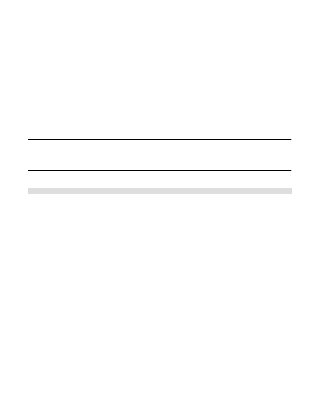
Table 13. Process Temperature Input Information
Process Temperature Input Temperature compensation
None Disable.
Manual Enable. input process temperature into DLC3100 manually.
RTD
Enable. install RTD to the DLC3100 terminal box. DLC3100 will base on the RTD reading and derive the
temperature of the process.
When Temperature Compensation is enabled (by selecting Manual or RTD in Process Temperature Input), select the
process fluid type, and enter the temperature/density table. The DLC3100 will use the best matched compensated
density value from the pre-loaded fluid type tables in DLC3100 for level measurement based on the actual process
temperature. If Custom Fluid is selected, input Temperature/Density values to custom fluid table. For level
measurement applications, only the lower fluid table is required. For interface measurement applications, both upper
fluid and lower fluid tables are required. Neither table is used for density applications.
Note
A minimum of two pairs of temperature/density values must be entered to the table. The temperatures entered must be in
ascending order.
Manual Setup
AMS Configure > Manual Setup
Field Communicator Configure > Manual Setup (3)
The DLC3100 digital level controller communicates via the HART protocol. This section describes the advanced
features that can be accessed with the DD/Field Communicator.
Note
Changing setup parameters will require instrument protection to be disabled, and the instrument to be put out of service. Place
the loop into manual operation before putting device out of service as the DLC3100 output may not be valid.
When the DLC3100 is out of service, it is locked for exclusive access by the Primary/Secondary master that put it out of service. If
the instrument reports Locked by HART or Access Restricted when you attempt to configure it, and a master of the original
priority is not available, use Force Mode on the Local User Interface menu to force the instrument mode to In Service. You will
then be able to take it out of service with your own master to make changes.
24
Page 25

Instruction Manual
D104213X012
General
Group Name Description
Device Information
Serial Numbers
Instrument Clock
Device
DLC3100 Digital Level Controller
July 2019
Tag
A unique tag to identify the HART device, up to 8
characters.
Date Calibration date entered by user.
Descriptor
A loop descriptor with a maximum length of 16
characters.
Message A message with a maximum length of 32 characters.
Instrument Serial Number Serial number on the instrument nameplate.
Sensor Serial Number Serial number on the sensor nameplate.
Dynamic date on the instrument clock for use in
Instrument Date
stamping logged events. The order of year, month and
day depends on the setting of the operating system.
Instrument Time
Time of day (hh:mm:ss) on instrument clock for use in
stamping logged events.
Group Name Description
Application Measurement application: Level, Interface or Density
PV Upper Range Value
Primary Variable
PV Lower Range Value
Primary Value Offset
Analog Output Action Analog Output Action
PV Upper Sensor Limit
Sensor Limits
PV Lower Sensor Limit
PV Damping
Damping
Input Filter Time
Defines the operational endpoint from which the
20 mA or 100% of the percent range are derived.
Defines the operational endpoint from which the 4 mA
or 0% of the percent range are derived.
The primary variable value you want the instrument to
report when physical level is at bottom of a displacer.
Defines whether loop current increases/decreases
when level changes.
Direct – Loop current increases as the fluid level
increases.
Reverse – Loop current decreases as the fluid level
increases.
Indicates the maximum usable value for the Upper
Range value.
Indicates the minimum usable value for the Lower
Range value.
Time constant of filter applied to PV signal after all
compensation and before generating AO command.
Time constant of filter applied to torque tube sensor
input signal.
25
Page 26

DLC3100 Digital Level Controller
July 2019
Sensor
Group Name Description
Displacer Length Full length of the displacer.
Displacer Volume Volume of the displacer.
Displacer Weight Weight of the displacer.
Sensor Dimensions
Sensor Units
Torque Tube
Driver Rod Length Length of the moment arm.
Instrument Mounting
Length Units
Volume Units The selected units for displacer volume.
Weight Units The selected units for displacer weight.
Temperature Units
Fluid Density Units
Torque Rate Units Unit of torque rate.
Compensated Torque Rate
Torque Tube Material
Torque Tube Wall The thickness of the torque tube used.
Sensor Type 249 model level sensor used.
Instruction Manual
D104213X012
The location of the instrument when mounted on the
level sensor, whether it is to the right or left of
displacer.
The selected units for length measurements and
parameters.
The selected units for temperature measurements and
parameters.
The selected units for density measurements and
parameters.
Compound torsion rate of torque tube, pilot shaft, and
instrument flexure, computed during calibration.
Selected torque tube material for torque tube
temperature compensation.
Process
Group Name Description
Process Fluid
Temperature
Compensation
Process Fluid Actual process fluid to be measured.
Process Fluid Compensated
Density
Fluid Density Units
Process Temperature Input
Actual fluid density after temperature compensation.
The selected units for density measurements and
parameters.
Temperature input to the instrument via RTD, manually
input, or none.
Process Temperature Actual temperature of the process.
Temperature Units
The selected units for temperature measurements and
parameters.
26
Page 27

Instruction Manual
D104213X012
HART
Group Name Description
Communication Settings
Polling Address
PV is
SV is
Variable Mapping
TV is
QV is
Safety Recovery (DLC3100 SIS)
Group Name Description
Recovery Trip Recovery Mode
DLC3100 Digital Level Controller
July 2019
The polling address for the instrument. If a
point-to-point configuration is used, enter 0. If a
multidrop configuration is used, enter a value in the
range of 1 to 62, and disable loop current mode.
Field device dynamic variable that has been mapped
into the Primary Variable.
Field device dynamic variable that has been mapped
into the Secondary Variable.
Field device dynamic variable that has been mapped
into the Tertiary Variable.
Field device dynamic variable that has been mapped
into the Quaternary Variable.
Auto: DLC3100 SIS is in Trip Alarm Current state; when
the alarm current condition is cleared, the instrument
will automatically revert back to normal operating
current condition.
Manual: DLC3100 SIS is in Trip Alarm Current state, when
the alarm current condition is cleared, instrument will
remain in trip alarm current state. You will need to
manually reset the instrument by “Safety Reset”.
27
Page 28

DLC3100 Digital Level Controller
July 2019
Instruction Manual
D104213X012
Alert Setup
Note
The DLC3100 has to be put out of service when carrying out Alert Setup. Place the loop into manual operation before putting
device out of service as the output will not be valid.
When the DLC3100 is out of service, it is locked for exclusive access by the Primary/Secondary master that put it out of service. If
the instrument reports Locked by HART or Access Restricted when you attempt to configure it, and a master of the original
priority is not available, use Force Mode on the Local User Interface menu to force the instrument mode to In Service. You will
then be able to take it out of service with your own master to make changes.
Primary Variable
Group Description
PV Alert Deadband The monitored primary variable must move more than this value to clear the alert.
Indicates that the primary variable has violated the user-specified high high alert point.
PV Hi Hi Alert
PV Hi Alert Indicates that the primary variable has violated the user-specified high alert point.
PV Lo Alert Indicates that the primary variable has violated the user-specified low alert point.
PV Lo Lo Alert
Output current will be set to alarm current depending on the hardware Alarm Switch
configuration.
Indicates that the primary variable has violated the user-specified low low alert point.
Output current will be set to alarm current depending on the hardware Alarm Switch
configuration.
Note
PV alert settings will be affected by the analog output action. See tables 14, 15, and 16. When setting analog output action, always
check the PV alert settings to make sure the alert thresholds are according to the analog output action.
Table 14. Analog Output Action - Direct
Direct Action
(Span = Upper Range Value – Lower Range Value)
Alarm Variable Default Value in unit Default Value in percentage
PV Hi Hi Alarm Upper Range Value 100%
PV Hi Alarm 95% span + Lower Range Value 95%
PV Lo Alarm 5% span + Lower Range Value 5%
PV Lo Lo Alarm Lower Range Value 0%
Table 15. Analog Output Action - Reverse
Reverse Action
(Span = Lower Range Value – Upper Range Value)
Alarm Variable Default Value in unit Default Value in percentage
PV Hi Hi Alarm Lower Range Value 0%
PV Hi Alarm 95% span + Upper Range Value 5%
PV Lo Alarm 5% span + Upper Range Value 95%
PV Lo Lo Alarm Upper Range Value 100%
28
Page 29

Instruction Manual
D104213X012
DLC3100 Digital Level Controller
July 2019
For example, with a 14 inch displacer, PV Hi and PV HiHi alert will be active when the fluid level goes beyond the alert
points. Likewise, PV Lo and PV LoLo will be active when the fluid level falls below the alert points.
Table 16. Example; 14 Inch Displacer
Action Range Value PV Alerts Units Percentage
URV 14 in
Direct
LRV 0 in
URV 0 in
Reverse
LRV 14 in
PV HiHi 13.3 in 95%
PV Hi 12.6 in 90%
PV Lo 1.4 in 10%
PV LoLo 0.7 in 5%
PV HiHi 13.3 in 5%
PV Hi 12.6 in 10%
PV Lo 1.4 in 90%
PV LoLo 0.7 in 95%
Rate Limit
Name Description
Displacer Rise Rate
Exceeded
Displacer Fall Rate
Exceeded
Indicates if the device detected a rise rate that exceeded the limit.
Indicates if the device detected a fall rate that exceeded the limit.
Temperature
Name Description
Process Temperature
Deadband
Instrument Temperature
Deadband
Process Temperature Hi
Alert
Process Temperature Lo
Alert
Instrument Temperature Hi
Alert
Instrument Temperature
Lo Alert
The process temperature must move more than this value to clear the alert.
The instrument temperature must move more than this value to clear the alert.
Indicates that the process temperature has violated the user-specified high alert
point.
Indicates that the process temperature has violated the user-specified low alert
point.
Indicates that the instrument temperature has violated the user-specified high alert
point.
Indicates that the instrument temperature has violated the user-specified the low
alert point.
29
Page 30

DLC3100 Digital Level Controller
July 2019
Instruction Manual
D104213X012
Operational
Name Description
Calibration Validity Alert
Analog Output Fixed Indicates that the output is in fixed current mode, not tracking process.
Analog Output Saturated Indicates that the analog output is saturated at 3.8 mA or 20.5 mA.
PV Out of Limits
Non-PV Out of Limits
Device Malfunction Indicates that the field device has malfunctioned due to a hardware error or failure.
PV AO Readback Fail
Lever Assembly Locked
Calibration in Progress Set if a calibration routine is currently running in the instrument.
Indicates that parameters affecting calibration validity have been changed since the
last calibration was accepted.
Indicates that the process applied to the primary variable is outside the operating
limits of the field device.
Indicates that the process applied to the non-primary variable is outside the
operating limits of the field device.
Indicates that the output readback for the primary variable has deviated by the
hard-coded limits.
Indicates that the lever assembly is in locked position and will not respond to level
changes.
Informational
Name Description
Configuration Changed
Device Configuration
Locked
Out of Service Indicates that the device is not in service.
Cold Start
Indicates that a modification has been made to the configuration of the field device
(configuration variable, tag descriptor or date).
Indicates that the device is locked for exclusive access or in write-protect mode.
Indicates that a reset or selftest of the field device has occurred, or power has been
removed and reapplied.
Input Compensation
Name Description
Fluid Value Crossed
Invalid Custom Table
Temp Out of
Compensation Range
Indicates that process fluid density values have crossed. The upper fluid density is
too close to 0.1 SGU or has become greater than the lower fluid density.
Indicates that the custom process fluid density table or torque tube table being used
for temperature compensation is invalid.
Indicates that the compensation temperature has exceeded the compensation table
limits.
30
Page 31

Instruction Manual
D104213X012
DLC3100 Digital Level Controller
Hardware
Name Description
Reference Voltage
Failed
Hall Sensor Alert
RTD Sensor Alert
Hall Diagnostic Failed Indicates that the internal hall diagnostics has possible failure in the Hall circuitry.
RTD Diagnostic Failed Indicates that the device has failed to diagnose the integrity of the RTD.
Instrument
Temperature Sensor
Alert
Indicates that the reference voltage for the Analog/Digital converter is outside the
hard-coded limits.
Indicates that the hall sensor reading has not been changing for 10 consecutive samples
or has violated one of the hard-coded limits.
Indicates that the apparent resistance measured at the RTD terminals is less than 10 ohms
or greater than 320 ohms.
Indicates that both mainboard temperature sensors are reporting outside operating
temperature range or differ by more than 10 degC.
Program and Memory
Name Description
Watchdog Reset
Executed
Program Memory
Failed
NVM Error Indicates that data in the critical section of configuration memory is corrupt.
Program Flow Error Indicates that the instrument is not performing the expected series of calculations.
EEPROM Write
Accumulator
RAM Test Error Alert Indicates that an on-going RAM test has detected possible corruption in the critical data.
EEPROM Daily Write
Accumulator
Indicates that the watchdog timer has timed out, triggering a hardware reset.
Indicates that the program memory is corrupt.
Indicates that the total number of EEPROM writes has exceeded 950,000 cycles.
Indicates that the total number of EEPROM writes has exceeded 160 times within the day.
July 2019
Alert Record
Name Description
Alert Record Not
Empty
Alert Record Full
Instrument Time Not
Set
Indicates that the alert record has entries.
Indicates that the number of alert events has met or exceeded the storage capacity of the
instrument.
Indicates that the instrument time was not initialized after the last power cycle.
31
Page 32

DLC3100 Digital Level Controller
July 2019
Calibration
AMS Configure > Calibration
Field Communicator Configure > Calibration (2-4)
Two Points Calibration
Two Points
Calibration
Instruction Manual
D104213X012
st
nd
Turn on/off
temperature
compensation
No
Set DLC3100 to
“Not In Service”
Running at
process
conditions?
Yes
Select units for
PV
measurement
Capture 1
calibration point
Adjust level
by at least 5% of
nominal span
Capture 2
calibration point
Set DLC3100 to
“In Service”
Two-Points Calibration is usually the most accurate method for calibrating the sensor. It uses independent
observations of two valid process conditions, together with the hardware dimensional data and specific gravity
information, to compute the effective torque rate of the sensor. The two data points can be separated by any span
between a minimum of 5% to 100%, as long as they remain on the displacer. Within this range, the calibration accuracy
will generally increase as the data point separation gets larger. Accuracy is also improved by running the procedure at
process temperature, as the temperature effect on torque rate will be captured. (It is possible to use theoretical data
to pre-compensate the measured torque rate for a target process condition when the calibration must be run at
ambient conditions).
32
Page 33

Instruction Manual
D104213X012
Min/Max Calibration
DLC3100 Digital Level Controller
July 2019
Min/Max
Calibration
Set DLC3100 to
“Not In Service”
Turn on/off
temperature
compensation
No
Running at
process
conditions?
Yes
Capture Min
or Max
buoyancy?
Min
Confirm fluid(s)
density
Establish min
buoyancy and
capture
Establish max
buoyancy and
capture
Max
Establish max
buoyancy and
capture
Establish min
buoyancy and
capture
Set DLC3100 to
“In Service”
Min/Max Calibration can be used to calibrate the sensor if the process condition can be changed to the equivalent of a
completely dry and completely submerged displacer, but the actual precise intermediate values cannot be observed
(eg. no sight glass is available, but the cage can be isolated and drained or flooded). Correct displacer information and
the SG of the test fluid must be entered before performing this procedure.
33
Page 34

DLC3100 Digital Level Controller
July 2019
Weight Calibration
Instruction Manual
D104213X012
Weight
Calibration
Set DLC3100 to
“Not In Service”
Apply larger weight
of no more than max
load allowed on driver
rod and capture 1
calibration point
Apply smaller weight
than previous step on
driver rod and capture
nd
2
calibration point
1
Weight
st
Weight/
Counter-Weight?
Counter-
Weight
Apply smaller counter-
weight of at least min
load allowed and capture
st
calibration point
1
Apply larger counter-
weight than previous
step and capture 2
nd
calibration point
Set DLC3100 to
“In Service”
1 REFER TO TABLE 17 FOR MAXIMUM LOAD ALLOWED ON TORQUE TUBE.
Weight Calibration may be used on the bench or with a calibration jig that can apply a mechanical force to the driver
rod to simulate displacer buoyancy changes. It allows the instrument and sensor to be calibrated using equivalent
weights or force inputs instead of using the actual displacer buoyancy changes. If the displacer information has been
entered prior to beginning the procedure, the instrument will be able to compute reasonable weight value
suggestions for the calibration. The weight values suggested during the weight calibration aim to achieve maximum
torque tube rotation for better accuracy. It does not necessary mean the weight at 0% or 100%. The only preliminary
data essential for the correct calibration of the torque rate is the length of the driver rod being used for the calibration.
Weight equivalent to the net displacer weight at two valid process conditions must be available. The sensor must have
been sized properly for the expected service, so that the chosen process conditions are in the free motion linear range
of the sensor.
Table 17. Maximum Unbuoyed Displacer Weight
Sensor Type Torque Tube Wall Thickness Displacer Weight, WT (lb)
249, 249B, 249BP
249C, 249CP
249VS
249L, 249P
1. High pressure Class 900 through 2500.
34
(1)
249K
Thin
Standard
Heavy
Standard
Heavy
Thin
Standard
Thin
Standard
Thin
Standard
3.3
5.0
9.5
4.0
6.4
3.0
5.5
4.5
8.5
3.8
7.3
Page 35

Instruction Manual
D104213X012
Two Points Time Delay Calibration
Two Points
Time Delay
Calibration
DLC3100 Digital Level Controller
July 2019
Turn on/off
temperature
compensation
No
Set DLC3100 to
“Not In Service”
Running at
process
conditions?
Yes
Select units for
PV
measurement
First point
captured?
No
Capture 1
calibration point?
st
Yes
No
Use
previously
captured 1
point?
Select units for
measurement
Capture 2
calibration point
Set DLC3100 to
“In Service”
st
Yes
PV
nd
Two Points Time Delay is a two points calibration in which the two points captured can be taken some time apart. The
first point is captured and stored indefinitely until the second point is captured. All instrument configuration data is
needed to perform a Two Points Time Delay Calibration.
35
Page 36

DLC3100 Digital Level Controller
July 2019
Instruction Manual
D104213X012
Zero Trim
Turn on/off
temperature
compensation
No
Zero Trim
Partial
Calibration
Set DLC3100 to
“Not In Service”
Running at
process
conditions?
Yes
Select units for
PV
measurement
Input observed
PV
Gain Trim
Turn on/off
temperature
compensation
No
Gain Trim
Partial
Calibration
Set DLC3100 to
“Not In Service”
Running at
process
conditions?
Yes
Select units for
PV
measurement
Input observed
PV
Set DLC3100 to
“In Service”
Trim Zero computes the value of the input angle
required to align the digital Primary Variable with the
user’s observation of the process, and corrects the
stored input zero reference, assuming that the
calibration gain is accurate.
Set DLC3100 to
“In Service”
Gain Trim trims the torque rate value to align the
digital Primary Variable with the user’s observation.
This calibration assumes that sensor zero is already
accurate and only a gain error exists. Actual process
condition must be nonzero and able to be measured
independently. Configuration data must contain
density of calibration fluid(s), displacer volume, and
driver rod length.
Torque Rate Gain
Torque Rate Gain allows you to input the torque rate.
36
Page 37

Instruction Manual
D104213X012
DLC3100 Digital Level Controller
July 2019
Accuracy Considerations
Effect of Proportional Band
If a DLC3100 with level sensor is operating at low Proportional Band [PB = 100% times (full span torque tube rotation) /
(4.4 degrees)], there will be a degradation factor of about (100%)/(PB%) on the device accuracy specifications.
Note
This formula is most correct for linearity errors that are relatively steep‐sided. If the linearity error curve shape is simple with
relatively gradual slope, the net effect of reducing span may be less. Instruments such as the DLC3100, that use a compensation
technique to reduce the residual mechanical or electrical non‐linearity, will generally have a complex shape for the net‐error curve.
If this is too much degradation, an improvement of 2.0 can be obtained by using a thin‐wall torque tube. Additional
gain can be achieved by increasing the displacer diameter. Available clearance inside the cage, and the need to keep
the net displacer weight at the highest and lowest process conditions within the usable range of the torque tube/driver
rod combination, place practical limits on how much the sizing can be adjusted.
With an overweight displacer, the calibration process becomes more difficult as the zero buoyancy condition will occur
with the linkage driven hard into a travel stop. In interface measurement application, it is recommended to calibrate
with actual process fluids (upper and lower fluids), or set the application to level and use water to calibrate the
DLC3100.
Density Variations in Interface Applications
A high sensitivity to errors in the knowledge of fluid density can develop in some interface applications.
For example: Suppose the whole input span is represented by an effective change in SG of 0.18. Then a change in the
actual SG of the upper fluid from 0.8 to 0.81 could cause a measurement error of 5.6% of span at the lowest interface
level. The sensitivity to the knowledge of a fluid density is maximum at the process condition where that fluid covers
all the displacer, zero at the opposite extreme process condition, and varies linearly between those points.
If the fluid density changes are batch‐related or very gradual, it may be practical to keep track of the SG of the fluid and
periodically reconfigure the DLC3100 density setting to match the actual process condition. Frequent automatic
updates to this variable are not advisable as the NVM location where it is stored has a write limit. If changes are only a
function of temperature, the characteristic of the fluid can be loaded once in the density table, and an RTD connected
to measure the process temperature and drive the temperature compensation table. If temperature is not the driving
influence, the best that can be done is to calibrate for the widest potential differential SG. This will keep the variations
as small a percentage of calibrated span as possible. Then calculate an alarm threshold that will prevent vessel over‐ or
under‐flow at the worst-case error.
37
Page 38

DLC3100 Digital Level Controller
July 2019
Instruction Manual
D104213X012
Extreme Process Temperatures
For applications that will run at extreme temperatures, the effect of process temperature on the torque tube must be
considered. Best results are obtained by running the torque tube calibration at actual process temperature. However,
the decrease in spring rate with temperature can be simulated at room temperature by increasing the load on the
torque tube during room‐temperature calibration. This will produce the same deflection that would occur at actual
process conditions. This compensation is theoretical and not perfect, but is still an improvement over ambient
calibration with no attempt at compensation.
Note
For additional information, refer to the Simulation of Process Conditions for Calibration of Fisher Level Controllers and
Transmitters instruction manual supplement (D103066X012
), available at Fisher.com.
Temperature Compensation
AMS Configure > Manual Setup > Process
Field Communicator Configure > Manual Setup > Process (2-3-4)
If the process temperature departs significantly from calibration temperature, temperature compensation can be
enabled. By selecting Process Temperature Input to either RTD or Manual, the temperature compensation will be
enabled. DLC3100 digital level controller will use the correct fluid density from the default fluid table (depending on
fluid type selected, see table 18 for example) or custom table (user input) based on the actual process temperature.
Custom Table must have ascending temperature inputs.
Table 18. Example Specific Gravity vs Temperature Table for Saturated Water
Data Point
1
2
3
4
5
6
7
8
9
10
_C _F
26.7
93.3
176.7
248.9
304.4
337.8
354.4
365.6
371.1
374.7
Temperature
80.0
200.0
350.0
480.0
580.0
640.0
670.0
690.0
700.0
706.5
Specific Gravity
0.9985
0.9655
0.8935
0.8040
0.7057
0.6197
0.5570
0.4940
0.4390
0.3157
You can also correct the temperature effect by applying a correction factor to the torque tube rate. Interpolate the
correction factor from the material‐specific tables of theoretical normalized modulus of rigidity versus temperature,
as described in Simulation of Process Conditions for Calibration of Fisher Level Controllers and Transmitters
(D103066X012
). Multiply the measured torque tube rate (editable in Configure > Calibration > Trim Current
Calibration > Torque Tube Gain) by the correction factor and enter the new value. This approach allows a better
approximation of the actual torque tube behavior at process conditions when calibration cannot be carried out at
process temperature.
38
Page 39

Instruction Manual
D104213X012
DLC3100 Digital Level Controller
July 2019
Section 5
Service Tools
Active Alerts
AMS Service Tools > Alerts
Field Communicator Services Tools > Alerts (3-1)
Alert Description
Configuration Changed
Calibration Validity
Cold Start Power has just been applied to the device or a device reset has occurred.
Analog Output Fixed The device is in Out of Service mode or in fixed current mode.
PV Hi PV is above the PV Hi alarm value.
PV Lo PV is below the PV Lo alarm value.
Process Temperature Too High Process temperature is above Process Temperature Hi alarm value.
Process Temperature Too Low Process temperature is below Process Temperature Lo alarm value.
Instrument Temperature Too High
Instrument Temperature Too Low
Alert Event Record Not Empty There is at least one entry in the device alert event record log.
Alert Event Record Full The Alert Event Record log has reached its maximum number of 30 entries.
Calibration in Progress The device is in calibration sequence.
Instrument Time Not Set Instrument time has not been set since power up.
Device Configuration Locked Instrument is in write protection mode or it is locked.
Lever Assembly Locked Lever assembly is in locked position.
Analog Output Saturated The loop current has been driven to saturation, 3.8 mA or 20.5 mA.
PV Out of Limits PV is less than 0% or more than 100%.
PV Range Out of Sensor Range PV has gone beyond 20% of sensor range.
Displacer Rise Rate Exceeded Level has risen greater than Rapid Rate Limit value.
Displacer Fall Rate Exceeded Level has fallen greater than Rapid Rate Limit value.
Fluid Values Crossed SG of two fluids are too close or have crossed.
Invalid Custom Table
Temperature Out of Compensation
Range
Non-PV Out of Limits
Program Flow Error Any critical or non-critical tasks missed execution for 5 consecutive cycles.
Any device configuration has been changed (configuration variable, tag
descriptor or date).
A parameter that directly affects PV calculation has been modified through
an inappropriate calibration method.
Electronics board temperature is above Electronics Temperature Hi alarm
value.
Electronics board temperature is below Electronics Temperature Lo alarm
value.
Custom table has less than 2 pairs input or temperature inputs are not in
ascending order.
The current temperature is beyond the valid table temperature range.
Instrument temperature is beyond the operating range.
Process temperature is beyond the range of -200 degC to 427 degC.
In Level or Interface application, compensated lower SG is outside the
range of density limits.
- continued on next page -
39
Page 40

DLC3100 Digital Level Controller
July 2019
Instruction Manual
Active Alerts (continued)
Alert Description
PV HiHi Alert The PV has gone above user-adjustable PV HiHi alarm threshold.
PV LoLo Alert The PV has gone below user-adjustable PV LoLo alarm threshold.
Any of the below alerts are active:
•Hall Sensor Alert
Device Malfunction
Reference Voltage Failed Internal reference voltage has deviated more than tolerance.
PV Analog Output
Readback Limit Failed
Instrument Temperature
Sensor Alert
Hall Sensor Alert Hall sensor reading is invalid.
RTD Sensor Alert The sensor reading for the process temperature is invalid.
Hall Diagnostics Failed Hall current readback has deviated from the driven current.
Program Memory Failed Ongoing flash checksum operation does not match firmware checksum.
NVM Error
RAM Test Error Alert Critical RAM data is corrupted.
Watchdog Reset
Executed
•Program Memory Failed
•NVM Error
•RAM Test Error Alert
PV Analog Output Readback has deviated from the driven current.
Electronics temperature sensors have failed.
Configuration data affecting the safety critical parameters in the memory is
corrupted.
Watchdog reset has just been performed.
D104213X012
Tests
AMS Service Tools > Maintenance > Tests
Field Communicator Service Tools > Maintenance > Tests (3-4-2)
Test Description
Instrument Display This is a LCD test. It will turn on/off all the pixels on LCD for 3 seconds.
Analog Output
This is a loop test. It allows changing of output current. This test has to be done when
the instrument is not in service.
40
Page 41

Instruction Manual
D104213X012
DLC3100 Digital Level Controller
Reset/Restore Device
AMS Service Tools > Maintenance > Reset/Restore Device
Field Communicator Service Tools > Maintenance > Reset/Restore Device (3-4-1)
Restore Factory Defaults will set the following parameters to default values:
Parameter Default Setting
Polling Address 0
Instrument Mounting Right of Displacer
Temperature Compensation Disable
Process Temperature Input None
Torque Tube Material K-Monel
Application Level
Displacer Length 14 in
Displacer Volume 99 in
Displacer Weight 4.75 lb
Driver Rod Length 8 in
Lower Fluid Density 1 SGU
Torque Rate 8.80662 lb-in/deg
Write Protection Disable
Trip Recovery Mode (DLC3100 SIS only) Manual Recovery
PV Damping 0 sec
Input Filter Time 0 sec
Level Offset 0 in
PV HiHi Alert 14 in
PV LoLo Alert 0 in
PV Hi Alert 13.3 in
PV Lo Alert 0.7 in
PV Alert Deadband 0.14 in
HART Universal Revision 7
Instrument Temperature Hi Alert 176 degF
Instrument Temperature Lo Alert -40 degF
Instrument Temperature Deadband 9 degF
Process Temperature Hi Alert 797 degF
Process Temperature Lo Alert -328 degF
Process Temperature Deadband 9 degF
Rate Limit 1.778 in
Maximum Recorded Temperature 0 degF
Minimum Recorded Temperature 176 degF
3
July 2019
Reset Device is equivalent to power cycle the DLC3100 digital level controller.
41
Page 42

DLC3100 Digital Level Controller
July 2019
Instruction Manual
D104213X012
Section 6
Maintenance and Troubleshooting
The DLC3100 digital level controller features a modular design for easy maintenance. If there is a malfunction, check
for an external cause before performing the diagnostics describe in this section.
Sensor parts are subject to normal wear and must be inspected and replaced as necessary. For sensor maintenance
information, refer to appropriate sensor instruction manual.
WARNING
To avoid personal injury, always wear protective gloves, clothing, and eyewear when performing any maintenance
operations.
Personal injury or property damage due to sudden release of pressure, contact with hazardous fluid, fire, or explosion can
be caused by puncturing, heating, or repairing a displacer that is retaining process pressure or fluid. This danger may not
be readily apparent when disassembling the sensor or removing the displacer. Before disassembling the sensor or
removing the displacer, observe the appropriate warnings provided in the sensor instruction manual.
Check with your process or safety engineer for any additional measures that must be taken to protect against process
media.
CAUTION
When replacing components, use only components specified by the factory. Always use proper component replacement
techniques, as presented in this manual. Improper techniques or component selection may invalidate the approvals and
the product specifications, as indicated in table 1. It may also impair operations and the intended function of the device.
Alert Messages
In addition to the level measurement and output current, the LCD displays abbreviated alert messages for
troubleshooting the digital level controller. To check for alert messages, push the left button when the LCD is in Home
screen with “ALERTS” shown at the bottom of the LCD. A description of each alert message is shown in table 19.
42
Page 43

Instruction Manual
D104213X012
Table 19. Alert Messages
Alert Description
DEVICE MALFUNC Device Malfunction
ANALOG O/P | FIXED Analog Output Fixed
ANALOG O/P | SATURATED Analog Output Saturated
NON-PV | OUT OF LIMITS Non-PV Out of Limits
PV | OUT OF LIMITS PV Out of Limits
PROG MEM FAIL Program Memory Failed
TEMP SENSOR Instrument Temp Sensor
HALL SENSOR Hall Sensor
HALL DIAG FAIL Hall Diagnostics Failed
REF VOLT FAIL Reference Voltage Failed
PV ANALOG O/P | READBACK FAIL PV Analog Output Readback Limited Failed
RTD DIAG FAIL RTD Diagnostics Failed
RTD SENSOR RTD Sensor
CALIBRATION | IN PROGRESS Calibration In Progress
CAL VALIDITY Calibration Validity
PROG FLOW ERR Program Flow Error
INST TIME| NOT SET Instrument Time Not Set
PV HI PV Hi
PV HI HI PV Hi Hi
PV LO PV Lo
PV LO LO PV Lo Lo
PROC TEMP | TOO HIGH Process Temperature Too High
PROC TEMP | TOO LOW Process Temperature Too Low
INST TEMP | TOO HIGH Instrument Temperature Too High
INST TEMP | TOO LOW Instrument Temperature Too Low
FLUID VALUES | CROSSED Fluid Values Crossed
TEMP OUT OF | COMP RANGE Temperature Out of Compensation Range
CUSTOM TABLE | INVALID Invalid Custom Table
RISE RATE | EXCEEDED Displacer Rise Rate Exceeded
FALL RATE | EXCEEDED Displacer Fall Rate Exceeded
WATCHDOG RESET Watchdog Rest Executed
RAM ERROR RAM Test Error
NVM ERROR NVM Error
OUT OF SERVICE Instrument Out of Service
EEPROM WRITE | EXCEEDED EEPROM Write Exceeded
EEPROM DAILY | WRITE EXCEEDED EEPROM Daily Write Exceeded
DLC3100 Digital Level Controller
July 2019
Hardware Diagnostics
If a malfunction is suspected despite the absence of diagnostic alert messages on the LCD, follow the procedures
described in table 20 to verify that the digital level controller hardware and process connections are in good working
order. Under each of the major symptoms, specific suggestions are offered for solving problems. Always deal with the
most likely and easiest-to-check conditions first.
43
Page 44

DLC3100 Digital Level Controller
July 2019
Table 20. Troubleshooting
Symptom Potential Cause Corrective Action
Device Description
Analog Output is within valid
range but instrument does not
communicate with Field
Communicator
Output at 0mA
Fixed Output at <= 3.6mA
Fixed Output at 3.8mA Low Saturation
Fixed Output at 20.5mA High Saturation
Fixed Output at >= 21mA
Output is within 4-20mA range,
but does not track displayed PV
value:
•Gain error
•Low saturation occurs at
value higher than 3.8mA
•High saturation occurs at a
value lower than 20.5mA
Output Drifting while at fixed
process input
Loop Wiring
Terminal Box
Main Electronics Board Replace the Main Electronics Board with a known good part.
Loop Wiring
Terminal Box
Main Electronics Board Replace the Main Electronics Board with a known good part.
Alarm Condition
(Alarm Low setting)
Alarm Condition
(Alarm High setting)
Main Electronics Board
Sensor
Transducer Module
Main Electronics Board
Configuration Data
Instruction Manual
D104213X012
Make sure the Field Communicator has the correct Device
Description to communicate with the DLC3100 digital level
controller.
Check resistance between the power supply and the Field
Communicator connection. The net resistance in the loop must be
between 230 and 600ohms for HART communication.
Check for adequate voltage to the digital level controller. Refer to
figure 10 for requirements. Some models of battery operated field
calibrators do not have sufficient compliance voltage to operate a
DLC3100 over the entire output current range.
Check for excessive capacitance in the field wiring (Isolate the
instrument from field wiring and try to communicate locally).
The terminal box may have developed a high internal resistance.
Try replacing the terminal box electronics board.
Check for open circuit.
Check for proper polarity at the +/- terminals.
Check for adequate voltage to the digital level controller.
Check resistance between Loop Power “+” and “T” terminals of
terminal box. If greater than 1.1 ohm, the terminal sense resistor
may be damaged. Replace the terminal box electronics.
Check LCD for alert messages to isolate failures.
For DLC3100 SIS, check if the digital level controller is locked in
safety and requires a manual reset.
Check PV against the PV HiHi and PV LoLo alarm threshold and
deadband setting, if these alarms are enabled.
Check the PV against the upper and lower range values. Check
actual process condition and calibration adjustments.
Check the PV against the upper and lower range values. Check
actual process condition and calibration adjustments.
Check LCD for alert messages to isolate failures.
For DLC3100 SIS, check if the digital level controller is locked in
safety and requires a manual reset.
Check PV against the PV HiHi and PV LoLo alarm threshold and
deadband setting, if these alarms are enabled.
Connect the Field Communicator and run a Loop Test. If the forced
output does not track the commands, replace the Main Electronics
Board.
Check torque tube rate change versus temperature per figure 6.
Use appropriate material for process temperature.
Pre-compensate the calibration for target process condition.
Connect the Field Communication and check instrument
temperature. If instrument temperature value is extreme, replace
the whole DLC3100 digital level controller.
Connect the Field Communicator and run Loop Test. Leave
instrument in fixed current mode at 12 mA command and observe
analog output variation with ambient temperature. If drift exceeds
specifications, replace the main electronics board.
Connect the Field Communicator and check stored Specific Gravity
values against independent measurement of process density. If
process SG has changed from calibration values, correct the SG in
configuration to match the process.
-continued-
44
Page 45

Instruction Manual
D104213X012
DLC3100 Digital Level Controller
Table 20. Troubleshooting (continued)
Symptom Potential Cause Corrective Action
If output current enters a limit cycle between zero and a value
Erratic Output Loop Wiring
Erratic display on LCD
Push Buttons Stuck Push Buttons Assembly Replace front cover assembly.
Loop Wiring Check for excessive loop resistance or low compliance voltage.
LCD Assembly Replace front cover assembly with known good part.
within the 4-20 mA range when level reaches some arbitrary upper
threshold, check for excessive loop resistance or low compliance
voltage.
Figure 10. Power Supply Requirements and Load Resistance
Maximum Load = 43.5 X (Available Supply Voltage - 12.0)
783
July 2019
Load (Ohms)
250
0
10 20 2515
12 30
LIFT‐OFF SUPPLY VOLTAGE (VDC)
Operating
Region
Removing the DLC3100 from the Sensor
Because the DLC3100 digital level controller has a modular design, most of the service and maintenance to the digital
level controller can be done without removing it from the sensor. However, if it is necessary to replace sensor to
instrument mating parts or parts in the transducer housing, or to perform bench maintenance, perform the following
procedures to remove the digital level controller from the sensor.
WARNING
On an explosion proof instrument, remove the electrical power before removing the instrument covers in a hazardous
area. Personal injury or property damage may result from fire and explosion if power is applied to the instrument with the
covers removed.
45
Page 46

DLC3100 Digital Level Controller
July 2019
Instruction Manual
D104213X012
Tools Required
Table 21 lists the tools required for maintaining the DLC3100 digital level controller.
Table 21. Tools Required
Tool Size Usage
Hex Key 2 mm Terminal box cover set screw (key 34)
Hex Key 6 mm Front Cover screws (key 49)
Hex Key 4 mm Lever assembly mount cap screws (key 11)
Hex Socket 10 mm Coupling nut
Open-end 13 mm DLC3100 mounting nuts (key 15)
Small Flat Blade Screwdriver - - -
1. Loosen the set screw (key 34) in the terminal box cover assembly (key 7) so that the cover can be unscrewed from
the terminal box.
2. After removing the cover, note the location of field wiring connections and disconnect the field wiring from the
wiring terminals.
3. As shown in figure 11, locate the access handle on the bottom of the transducer housing. Push the handle button
and slide toward the front of the DLC3100 (locked position), to expose the access hole. Be sure the locking handle
drops into the detent.
Terminal screws
Electronics module mounting screws
Figure 11. Access Handle
ACCESS HOLE
ACCESS HANDLE
- LOCK (ACCESS HOLE EXPOSED)
- UNLOCK (ACCESS HOLE COVERED)
X1499
Note
If the access handle will not slide, the sensor linkage is most likely in an extreme position. When the lever assembly is at a hard stop
inside the housing, the locking pin on the access door may not be able to engage the mating slot in the lever assembly. This
condition can occur if the displacer has been removed, if the sensor is lying on its side, or if the instrument had been coupled to the
sensor while the displacer was not connected. To correct this condition, manipulate the sensor linkage to bring the lever assembly
to within approximately 4 degrees of the neutral position before attempting to slide the handle. A probe inserted through the top
vent of the 249 head may be required to deflect the driver rod to a position where the lever assembly is free.
46
Page 47

Instruction Manual
D104213X012
DLC3100 Digital Level Controller
July 2019
4. Using a 10 mm deep well socket inserted through the access hole, loosen the shaft clamp (figure 11).
5. Loosen and remove the hex nuts (key 15) from the mounting studs (key 14).
CAUTION
Tilting the instrument when pulling it off of the sensor torque tube can cause the torque tube shaft to bend. To prevent
damage to the torque tube shaft, ensure that the digital level controller is level when pulling it off the sensor torque tube.
6. Remove the digital level controller as follows:
D For standard temperature applications carefully pull the digital level controller straight off the sensor torque
tube.
D For high temperature applications carefully pull the digital level controller straight off the sensor torque tube
shaft extension (key 58), shown in figure 12, and continue on with step 7.
7. Pull the heat insulator (key 57) off the mounting studs.
When re-installing the digital level controller, follow the appropriate procedure outlined in the quick start guide
(D104214X012
). Setup the digital level controller as described in the Initial Setup section.
Figure 12. Digital Level Controller Mounting on Sensor in High Temperature Applications
INSULATOR
(KEY 57)
SHAFT
EXTENSION
(KEY 58)
B2707
CAP SCREWS
(KEY 63)
SET SCREWS
(KEY 60)
SHAFT
COUPLING
(KEY 59)
SENSOR
WASHER
(KEY 78)
HEX NUTS
(KEY 34)
MOUNTING STUDS
(KEY 33)
DIGITAL LEVEL CONTROLLER
47
Page 48

DLC3100 Digital Level Controller
July 2019
Figure 13. DLC3100 Assembly Drawing
Instruction Manual
D104213X012
GG25866
Front Cover Assembly
WARNING
In an explosion proof or flame proof installation, remove the electrical power before removing the instrument covers in a
hazardous area. Personal injury or property damage may result from fire and explosion if power is applied to the
instrument with the covers removed.
Removing the Front Cover Assembly
Perform the following procedure to remove the front cover assembly:
1. Disconnect power to the digital level controller.
2. Loosen the four cap screws (key 49) and pull the front cover out slowly, as the main electronics board is connected
to the hall sensor electronics board cable and terminal box cable.
3. Disconnect the hall sensor board and terminal box electronics board cables from the main electronics board.
4. Unscrew the three screws holding the main electronics board and remove it from the LCD assembly.
5. Remove the two screws holding the LCD assembly and remove it from the front cover assembly.
48
Page 49

Instruction Manual
D104213X012
DLC3100 Digital Level Controller
July 2019
Replacing the Front Cover Assembly
Perform the following procedure to replace the front cover assembly:
1. Mount the LCD assembly onto the front cover assembly and tighten the two screws.
2. Mount the main electronics board onto the LCD assembly and tighten the three screws.
3. Connect the cables from the hall sensor board and terminal box electronics board to the main electronics board.
4. Make sure the O-ring is in place and install the front cover assembly to the digital level controller housing with the
four cap screws, and tighten to 35 N•m (310 lbf•in).
Main Electronics Board
Removing the Main Electronics Board
Note
The Main Electronics Board is potted and it is a non-repairable unit. If a malfunction occurs, the entire main electronics board must
be replaced.
WARNING
On an explosion proof instrument, remove the electrical power before removing the instrument covers in a hazardous
area. Personal injury or property damage may result from fire and explosion if power is applied to the instrument with the
covers removed.
1. Disconnect power to the digital level controller.
2. Remove the front cover and disconnect the cables of the hall sensor board and the terminal box electronics board
connected to the main electronics board.
3. Unscrew the three screws holding the main electronics board.
4. Firmly grasp the Main Electronics Board and remove it from the LCD assembly.
Replacing the Main Electronics Board
Perform the following procedure to replace the main electronics board:
1. Mount the main electronics board onto the LCD assembly.
2. Tighten the three mounting screws.
3. Install the cables of the hall sensor board and the terminal box electronics board to the main electronics board.
4. Install the front cover with the four cap screws and tighten to 35 N•m (310 lbf•in) torque value.
49
Page 50

DLC3100 Digital Level Controller
July 2019
Instruction Manual
D104213X012
LCD Assembly
Removing the LCD Assembly
WARNING
On an explosion proof instrument, remove the electrical power before removing the instrument covers in a hazardous
area. Personal injury or property damage may result from fire and explosion if power is applied to the instrument with the
covers removed.
1. Disconnect power to the digital level controller.
2. Remove the front cover and disconnect the cables of the hall sensor board and the terminal box electronics board
connected to the main electronics board.
3. Remove the main electronics board
4. Loosen the two screws holding the LCD assembly to the front cover assembly.
Replacing the LCD Assembly
Perform the following procedure to replace the LCD assembly:
1. Mount the LCD assembly onto the front cover assembly.
2. Tighten the two mounting screws.
3. Connect the main electronics board to the LCD assembly and tighten the three mounting screws.
4. Install the cables from the hall sensor board and the terminal box electronics board to the main electronics board.
5. Install the front cover to the housing with the four cap screws and tighten to 35 N•m (310 lbf•in) torque value.
Terminal Box Electronics Board
The terminal box is located at the side of the housing and contains the terminal strips for field wiring connections.
WARNING
On an explosion proof instrument, remove the electrical power before removing the instrument covers in a hazardous
area. Personal injury or property damage may result from fire and explosion if power is applied to the instrument with the
covers removed.
Removing the Terminal Box Electronics Board
1. Disconnect power to the digital level controller.
2. Loosen the four cap screws and remove front cover assembly. Disconnect the terminal box electronics board cable
connected to the main electronics board.
3. Loosen the set screw (key 34) in the terminal box cover assembly (key 7) so that the cover can be unscrewed from
the terminal box.
50
Page 51

Instruction Manual
D104213X012
4. After removing the cover (key 35), note the location of field wiring connections and disconnect the field wiring from
the wiring terminals.
5. Remove the screw (key 68) and pull out the terminal box electronics board.
DLC3100 Digital Level Controller
July 2019
Replacing the Terminal Box Electronics Board
Note
Inspect all O-rings for wear and replace as necessary.
1. Orient the terminal box electronics board and carefully insert into the housing.
2. Ensure the cable of the terminal board electronics board goes through the housing.
3. Tighten the screws of the terminal box electronics board to the housing.
4. Connect the terminal box electronics board cable to the main electronics board.
5. Install the front cover assembly to the housing and tighten the four cap screws.
6. Connect the field wiring to the terminals on the terminal box electronics board.
7. Screw the terminal box cover assembly (key 7) completely onto the terminal box to seat the O-ring (key 16).
Loosen the cover (not more than 1 turn) until the set screw (key 24) aligns with one of the recesses in the terminal
box beneath the cover. Tighten the set screw to engage the recesses but not more than 0.88 N•m (7.8 lbf•in).
Packing for Shipment
If it becomes necessary to return the unit for repair or diagnosis, contact your Emerson sales office for returned goods
information.
CAUTION
Lock the lever assembly when shipping the standalone instrument, to prevent damage to the flexure.
Use the original shipping carton if possible.
51
Page 52

DLC3100 Digital Level Controller
July 2019
Instruction Manual
D104213X012
Section 7
Parts
Parts Ordering
Whenever corresponding with your Emerson sales office about this equipment, always mention the controller serial
number.
WARNING
Use only genuine Fisher replacement parts. Components that are not supplied by Emerson Automation Solutions should
not, under any circumstances, be used in any Fisher instrument. Use of components not supplied by Emerson may void
your warranty, might adversely affect the performance of the instrument, and could cause personal injury and property
damage.
Parts Kits
Kit Description Part Number
1* Small Hardware Spare Parts Kit GG51086X012
Includes Qty/kit
Set screw, key 34 2
Cap screw, key 21 2
Wire Retainer, key 17 2
Wire Retainer, key 18 2
Cap screw, key 11 2
Cap screw, key 13 4
Hex nut, key 15 8
Machine screw, key 8 4
Stud, key 14 8
2* Spare O‐Rings Kit GG51085X012
Includes Qty/kit
Key 16 2
Key 37 8
Key 38 2
Key 70 2
Parts List
Refer to figure 14 and 15.
Note
Contact your Emerson sales office for Part ordering information.
Key Description Part Number
1 Housing Assembly
2 Main Board Assembly
3 LCD Assembly GG25852X012
4 Cover Assembly GG25861X012
5 Nameplate, instrument
6 Terminal Box Assembly GG25784X012
7 Terminal Cover Assembly GG25788X012
8 Screw, machine
9 Transducer Housing
10 Lever Assembly
11 Screw, cap
12 Shield, coupling
13 Screw, cap
14 Stud
15 Nut, hex
16 O-ring
17 Wire Retainer
18 Wire Retainer
19 Pipe Plug
52
*Recommended spare parts
Page 53

Instruction Manual
D104213X012
Figure 14. Fisher DLC3100 Digital Level Controller Assembly
DLC3100 Digital Level Controller
July 2019
GG25838
APPLY LUBRICANT/ADHESIVE/THREADLOCK
53
Page 54

DLC3100 Digital Level Controller
July 2019
Instruction Manual
D104213X012
Key Description
20 Handle Assembly
21 Screw, cap
22 Guide, inner
23 Screw, machine
24 Bracket, plate
25 PCBA, Sensor
26 Hall Sensor Guard
27 Spring, compression
28 Button, striker
29 Pin, locking
30 Handle
31 Handle
32 Magnet
33 Adhesive
34 Screw, set
35 Terminal Box Cap
37 O-ring
38 O-ring
39 Cover Assembly
40 O-ring
42 Button, striker
43 Retainer
44 Button, membrane
46 Retainer
47 Screw, countersunk
48 Plate, face
49 Screw, cap
50 Adhesive, Loctite
51 Sealing Compound
52 Sealant
53 Lubricant, silicone sealant
54 Screw, machine
55 Retainer, screen
56 Cover
57 O-ring
58 Cover, front
Key Description
59 Potting compound
60 Magnet
61 Button, sticker
62 Pipe Thread Sealant
67 Label, blank
68 Screw, machine
69 Terminal Box Assembly
70 O-ring
71 Wire Assembly
72 Terminal Box Assembly
100 Coupling Block Subassembly
100a Coupling Block
100b Insert, front
100c Insert, back
101 Lever Subassembly
101a Lever
101b Roll Pin
101c Coupling Bellows
101d Counter Weight
101e Adhesive, 3M Scotch
102 Magnet and Lever Subassembly
102a Backup Plate
102b Magnet
102c Adhesive
102d Activator
103a Bolt, lock
103b Washer, lock, spring
103c Nut, clamp
103d Block, flexure
103e Flexure
103f Clamp, flexure
103g Screw, cap
103h Lubricant, grease
103j Adhesive, structural
103k Activator
103m Loctite 499
54
Page 55

Instruction Manual
D104213X012
Figure 15. Fisher DLC3100 Digital Level Controller Assembly
DLC3100 Digital Level Controller
July 2019
GG25861
APPLY LUBRICANT/ADHESIVE/THREADLOCK
GG25784
55
Page 56

DLC3100 Digital Level Controller
July 2019
Mounting Kits
Note
Contact your Emerson sales office
following mounting kits or for information on the availability of
additional mounting kits.
Key Description
249 Sensors with Heat Insulator
(figure 16)
57 Heat Insulator,
58 Shaft Extension
59 Shaft Coupling
60 Set Screw, hex socket (2 req'd)
61 Screw, hex hd (4 req'd)
78 Washer, plain (4 req'd)
for information on ordering the
Instruction Manual
D104213X012
Key Description
Masoneilan Sensors (figures 17 and 18)
12100 or 12800 without Heat Insulator
58 Shaft Extension
59 Shaft Coupling
60 Set Screw, hex socket (2 req'd)
61 Screw, hex hd (4 req'd)
62 Mounting Adapter
63 Screw, hex socket, (4 req'd)
12100 or 12800 with Heat Insulator
57 Heat Insulator
58 Shaft Extension
59 Shaft Coupling
60 Set Screw, hex socket (2 req'd)
61 Screw, hex hd (4 req'd)
62 Mounting Adapter
63 Screw, hex socket (4 req'd)
78 Washer, plain (4 req'd)
Figure 16. Mounting Kit for 249 Sensors with Heat Insulator
28B5741‐A
56
Page 57

Instruction Manual
D104213X012
DLC3100 Digital Level Controller
Figure 17. Mounting Kit for Masoneilan 12200 and 12300 Sensor without Heat Insulator
29B8444‐A
July 2019
Figure 18. Mounting Kit for Masoneilan 12200 and 12300 Sensor with Heat Insulator
29B8445‐A
57
Page 58

DLC3100 Digital Level Controller
July 2019
Instruction Manual
D104213X012
Key Description
12200 or 12300 without Heat Insulator
58 Shaft Extension
59 Shaft Coupling
60 Hex Socket Screw (2 req'd)
62 Mounting Adaptor
74 Hex Nut (4 req'd)
75 Hex Cap Screw (4 req'd)
12200 or 12300 with Heat Insulator
57 Heat Insulator
58 Shaft Extension
59 Shaft Coupling
61 Hex Cap Screw (4 req'd)
60 Hex Socket Screw (2 req'd)
62 Mounting Adaptor
74 Hex Nut (4 req'd)
75 Hex Cap Screw (4 req'd)
78 Washer, plain (4 req'd) not shown
Yamatake NQP Sensor
Without Heat Insulator
58 Shaft Extension
59 Shaft Retainer
60 Hex Socket Screw
62 Mounting Adaptor
63 Hex Socket Screw(3 req'd)
71 Hex Socket Screw (3 req'd)
72 Shaft Adapter
73 Hex Socket Screw (2 req'd)
With Heat Insulator
57 Heat Insulator
58 Shaft Extension
59 Shaft Retainer
60 Hex Socket Screw
61 Hex Cap Screw (4 req'd)
62 Mounting Adaptor
63 Hex Socket Screw (3 req'd)
71 Hex Socket Screw (3 req'd)
72 Shaft Adapter
73 Hex Socket Screw (2 req'd)
78 Washer, plain (4 req'd)
Key Description
Foxboro‐Eckardt Sensors
144LD without Heat Insulator
58 Shaft Extension
59 Shaft Coupling
60 Set Screw, hex socket (2 req'd)
62 Mounting Adapter
74 Hex Nut (4 req'd)
75 Hex Cap Screw (4 req'd)
144LD with Heat Insulator
57 Heat Insulator
58 Shaft Extension
59 Shaft Coupling
60 Set Screw, hex socket (2 req'd)
61 Screw, hex hd (4 req'd)
62 Mounting Adapter
74 Hex Nut (4 req'd)
75 Hex Cap Screw (4 req'd)
78 Washer, plain (4 req'd)
LP167 without Heat Insulator
58 Shaft Extension
59 Shaft Coupling
60 Set Screw, hex socket (2 req'd)
62 Mounting Adapter
63 Screw, hex socket (4 req'd)
Sunshade
Sunshades are available in two materials and orderable
as a kit.
Description Part Number
Sunshade
316 SST kit (see figure 19) GG44394X012
Glass Reinforced Plastic (GRP) kit (see figure 20) GG43970X012
Kits Include Qty/kit
Hex head cap screw, key S1 2
Flanged hex nut, key S2 2
Sunshade, key S3 1
Mounting bracket, key S4 1
58
Page 59

Instruction Manual
D104213X012
Figure 19. FIELDVUE DLC3100 with 316 SST Sunshade
DLC3100 Digital Level Controller
July 2019
S3
GG44394
Figure 20. FIELDVUE DLC3100 with Glass Reinforced Plastic (GRP) Sunshade
S2
S2
S1
S4
GG43970
S1
S3
S4
59
Page 60

DLC3100 Digital Level Controller
July 2019
Instruction Manual
D104213X012
Appendix A
Principle of Operation
HART Communication
The HART (Highway Addressable Remote Transducer) protocol gives field devices the capability of communicating
instrument and process data digitally. This digital communication occurs over the same two‐wire loop that provides
the 4-20 mA process control signal, without disrupting the process signal. In this way, the analog process signal, with
its faster update rate, can be used for control. At the same time, the HART protocol allows access to digital diagnostic,
maintenance, and additional process data. The protocol provides total system integration via a host device.
The HART protocol uses the frequency shift keying (FSK) technique based on the Bell 202 communication standard. By
superimposing a frequency signal over the 4-20 mA current, digital communication is attained. Two individual
frequencies of 1200 and 2200 Hz are superimposed as a sinewave over the 4-20 mA current loop. These frequencies
represent the digits 1 and 0 (see figure 21). The average value of this sinewave is zero, therefore no DC value is added
to the 4-20 mA signal. Thus, true simultaneous communication is achieved without interrupting the process signal.
Figure 21. HART Frequency Shift Keying Technique
+0.5 mA
A6174
0
-0.5 mA
1200 Hz
“1”
AVERAGE CURRENT CHANGE DURING COMMUNICATION = 0
2200 Hz
“0”
ANALOG
SIGNAL
The HART protocol allows the capability of multidropping, networking several devices to a single communications line.
This process is well suited for monitoring remote applications such as pipelines, custody transfer sites, and tank farms.
Multidrop Communication
“Multidropping” refers to the connection of several digital level controllers or transmitters to a single communications
transmission line. Communication between the host and the field instruments takes place digitally with the analog
output of the instruments deactivated. With the HART communications protocol, up to 15 field instruments can be
connected on a single twisted pair of wires or over leased phone lines. Multidrop installations are not recommended
where intrinsic safety is a requirement.
The application of a multidrop installation requires consideration of the update rate necessary from each instrument,
the combination of instrument models, and the length of the transmission line. Communication with the field
instruments can be accomplished with commercially available Bell 202 modems and a host implementing the HART
protocol. Each instrument is identified by a unique address (1-15) and responds to the commands defined in the HART
protocol.
60
Page 61

Instruction Manual
D104213X012
DLC3100 Digital Level Controller
July 2019
Figure 22 shows a typical multidrop network. Do not use this figure as an installation diagram. Contact your Emerson
sales office with specific requirements for multidrop applications.
Figure 22. Typical Multidropped Network
BELL 202
MODEM
HOST
POWER
SUPPLY
LOAD
The Field Communicator can test, configure, and format a multidropped DLC3100 digital level controller in the same
way as in a standard point‐to‐point installation, provided that it has been configured to scan for multiple polling
addresses.
Note
DLC3100 digital level controllers are set to address 0 at the factory, allowing them to operate in the standard point‐to‐point
manner with a 4-20 mA output signal. To activate multidrop communication, the address must be changed to a number between
1 and 15. This change deactivates the 4-20 mA analog output, sending it to 4 mA. The failure mode current also is disabled.
Digital Level Controller Operation
The DLC3100 digital level controller is a loop‐powered instrument that measure changes in liquid level, level of an
interface between two liquids, or density of a liquid. Changes in the buoyancy of a displacer suspended in a vessel vary
the load on a torque tube. The displacer and torque tube assembly constitute the primary mechanical sensor. The
angular deflection of the torque tube is measured by the instrument transducer, which consists of a magnet system
moving over a Hall effect device. A liquid crystal display (LCD) meter can display the analog output or process variable
(level, interface level, or density) in units or percent range.
The instrument uses a microcontroller and associated electronic circuitry to measure the process variable, provide a
current output, drive the LCD meter, and provide HART communications capability. Figure 23 shows the digital level
controller assembly. Figure 24 is a block diagram of the main components in the instrument electronics; the LCD
meter, the processor module, the transducer board, and the terminal board. The processor module contains the
microprocessor, the analog‐to‐digital (A/D) converters, loop interface, signal conditioning, the digital‐to‐analog (D/A)
output, power supply and interfaces to other boards.
61
Page 62

DLC3100 Digital Level Controller
July 2019
Figure 23. FIELDVUE DLC3100 Digital Level Controller Assembly
HOUSING ASSEMBLY
MAIN BOARD
ASSEMBLY
LCD METER
ASSEMBLY
Instruction Manual
D104213X012
TRANSDUCER
BOARD
COVER ASSEMBLY
GG25866
TERMINAL BOX
ASSEMBLY
Figure 24. FIELDVUE DLC3100 Digital Level Controller Principle of Operation
Transducer Module
Electronics
Temperature
Sensor
Electronics
Torque Tube
Rotation
Shaft Position
Transducer
Linearization Data
resident in NVM
Temperature
Sensors on
Processor
Module
Terminal
Box
TERMINAL
BOX COVER
Loop / HART
Interface
RTD
Process
LCD Meter
Temperature
Interface
The transducer board contains the Hall sensor, a temperature sensor to monitor the Hall sensor temperature, and an
EEPROM to store the coefficients associated with the Hall sensor. The terminal board contains the EMI filters, the loop
connection terminals, and the connections for the optional RTD used to measure process temperature.
62
Page 63

Instruction Manual
D104213X012
DLC3100 Digital Level Controller
July 2019
A level, density, or interface level change in the measured fluid causes a change in the displacer position (figure 25).
This change is transferred to the torque tube assembly. As the measured fluid changes, the torque tube assembly
rotates up to 4.4 degrees for a 249 sensor, varying the digital level controller output between 4 and 20 mA.
Figure 25. Typical Sensor Operation
TORQUE
TUBE
DISPLACER
W1389‐1
249 SENSOR (SIDE VIEW)
The rotary motion of the torque tube is transferred to the digital level controller lever assembly. The rotary motion
moves a magnet attached to the lever assembly, changing the magnetic field that is sensed by the Hall effect sensor.
The sensor converts the magnetic field signal to an electronic signal.
The microcontroller accepts the electronic signal, which is ambient‐temperature‐compensated and linearized. The
microcontroller can also actively compensate for changes in liquid specific gravity due to changes in process
temperature based on an input via HART protocol or via an optional RTD, if it is connected. The D/A output circuit
accepts the microcontroller output and provides a 4 to 20 mA current output signal.
During normal operation, when the input is between the lower and upper range values, the digital level controller
output signal ranges between 4 and 20 mA and is proportional to the input. See figure 26. If the input should exceed
the lower and upper range values, the output will continue to be proportional to the input until the output reaches
either 3.8 or 20.5 mA. At this time the output is considered saturated and will remain at this value until the input
returns to the normal operating range. However, should an alarm occur, the output is driven to either > 21 mA or < 3.6
mA, depending on the Alarm High/Low switch setting.
63
Page 64

DLC3100 Digital Level Controller
July 2019
Figure 26. Digital Level Controller Analog Output Signal
24
Instruction Manual
D104213X012
22
20
18
16
14
12
Output (mA)
10
8
6
4
2
-20% 0% 20% 40% 60% 80% 100% 120%
Output Saturated
(3.8 mA)
Normal Operation
Output during Alarm with
Alarm Switch in High Position
> 21.0 mA
Note
The alarm values are compliant with NAMUR NE‐43.
Output Saturated
(20.5 mA)
Output during Alarm with
Alarm Switch in Low
Position
< 3.6 mA
PV Range
Other circuits in the digital level controller provide reverse polarity protection, transient power surge protection, and
electromagnetic interference (EMI) protection.
64
Page 65

Instruction Manual
D104213X012
DLC3100 Digital Level Controller
Appendix B
Field Communicator Fast-Key Sequence and Menu Tree
Fast-Key Sequence
July 2019
Function/Variable Fast-Key-Sequence
Active Alerts 3-1-1
Alarm Switch 1-7-3-1-1
Alarm/Sat Levels 1-7-3-1-3
Alert Record Full 2-4-9-5
Alerts Recorded 2-4-9-4
1-2-3
Analog Output
Analog Output Action 2-3-2-2
AO Fixed 2-4-4-4
AO Readback Fail 2-4-4-6
AO Saturated 2-4-4-3
Application
Assembly Code 1-7-1-5-3
Calibration
Cal in Progress 2-4-4-9
Calibration in Use
Calibration Invalid 2-4-4-8
Calibration Method
Calibration/Setup Logs 3-4-1
Change AO Action 2-3-2-3
Change Application
Change Fluid
Change Level Offset 2-3-2-1-7
Change PV Range 2-3-2-1-5
Change/Sec Limit 2-4-2-2
Clear Alert Record 2-4-9-2
3-2-1-5
3-3-2
Hot Key - 3
1-3
2-3-2-1-1
3-2-1-1
Hot Key - 6
2-5-1
2-5-3
3-4-1-1
2-5-3-2
3-4-1-1-2
Hot Key - 4
2-3-2-1-2
Hot Key - 5
2-3-4-1-3
Function/Variable Fast-Key-Sequence
Clear Rate Alert 2-4-2-1
Cold Start 2-4-5-1
Comm Status 1-1-2
Communication 2-3-5-1
Comp. Torque Rate
Compensation
Config Changed 2-4-5-2
Daily Write Accum 2-4-8-6
Date 2-3-1-2
Density, PrcFld
Descriptor 2-3-1-3
DD Information 1-7-2-5
Dev Config Locked 2-4-5-4
Device ID 1-7-1-4
Device Malfunction 2-4-4-5
Device Revision 1-7-2-2
Device Setup 2-2-1
Device Status 1-1-1
Displacer Length 2-3-3-2-1
Displacer Volume 2-3-3-2-2
Displacer Weight 2-3-3-2-3
Distributor 1-7-1-2
Driver Rod Length 2-3-3-2-4
Fall Rate Alert 2-4-2-4
Firmware, Revision 1-7-2-4
Fluid Density Table 2-3-4-1-4
Fluid Density Units
Fluid Values Crossed 2-4-6-3
2-3-3-3-1
3-2-1-4
2-3-4-3-1
3-2-2-3-1
2-3-3-3-4
1-4-2
2-3-4-1-2
3-2-1-3-2
2-3-3-1-5
2-3-4-1-5
65
Page 66

DLC3100 Digital Level Controller
July 2019
Instruction Manual
D104213X012
Function/Variable Fast-Key-Sequence
Gain Trim 2-5-2-2
Hall Diagn Fail 2-4-7-4
Hall Sensor Alert 2-4-7-5
Hardware, Revision 1-7-2-3
Help, Device Setup 2-2-4
HW Information 2-3-3-4
Input Filter Time 2-3-2-5-2
Inst Temp D/band 2-4-3-4
Inst Temp Hi Alert 2-4-3-7
Inst Temp Lo Alert 2-4-3-8
Inst Temp Snsr Alert 2-4-7-6
2-4-3-2
Inst Temperature
3-2-2-1-1
3-3-3
Inst Time Not Set 2-4-9-3
Instrument Date 2-3-1-5
Instrument Mounting 2-3-3-2-5
Instrument SN
2-3-1-7-1
1-7-1-5-1
Instrument Time 2-3-1-6
Invalid Custom Table 2-4-6-1
LCD Test 3-4-2-1
Length Units 2-3-3-1-1
Level Offset 2-3-2-1-6
Lever Assy Locked 2-4-4-7
LOOP Test 3-4-2-2
Lower Range Value
Max Recorded,
Temperature Limit
2-3-2-1-4
2-4-1-2
3-2-2-1-2
Message 2-3-1-4
Min/Max, Calibration 2-5-1-1
Min Recorded,
Temperature Limit
3-2-2-1-3
Hot Key - 1
Mode
1-1-3
2-1
Model 1-7-1-3
Mounting Illustration 2-3-3-2-6
Non-PV Out of Limits 2-4-4-2
NVM Error 2-4-8-1
Out of Service 2-4-5-3
Polling Address 2-3-5-2
Primary Variable 3-3-1
Function/Variable Fast-Key-Sequence
Proc Temp D/band 2-4-3-3
Proc Temp Hi Alert 2-4-3-5
1-5
Proc Temp Input
2-3-4-2
3-2-2-2
Proc Temp Lo Alert 2-4-3-6
Process Density 3-2-1-3-1
Process Fluid
2-3-4-1-1
1-4-1
Process Setup 2-2-3
2-3-4-3-2
Process Temperature
2-4-3-1
3-2-2-3-2
Prog Memory Failed 2-4-8-4
Program Flow Error 2-4-8-5
Protection
Hot Key - 2
1-7-3-2
PV 3-2-1-2-2
PV Alert Units 2-4-1-3
PV Damping 2-3-2-5-1
PV Deadband 2-4-1-4
PV Hi Alert 2-4-1-6
PV Hi Hi Alert 2-4-1-5
PV Lo Alert 2-4-1-7
PV Lo Lo Alert 2-4-1-8
PV Lower Sensor Limit 2-3-2-4-2
PV Out of Limits 2-4-4-1
PV Setup 2-2-2
PV Upper Sensor Limit 2-3-2-4-1
PV Value
1-2-2
3-2-1-2-1
RAM Test Error 2-4-8-2
Ref Voltage Fail 2-4-7-3
Refresh Switch 1-7-3-1-2
Reset Device 3-4-3-2
Rise Rate Alert 2-4-2-3
RTD Diagn Fail 2-4-7-2
RTD Sensor Alert 2-4-7-1
Sensor SN
1-7-1-5-2
2-3-1-7-2
Sensor Type 2-3-3-3-6
Set Factory Defaults 3-4-3-1
Simple Zero/Span 2-5-1-5
66
Page 67

Instruction Manual
D104213X012
DLC3100 Digital Level Controller
July 2019
Function/Variable Fast-Key-Sequence
Tag
1-7-1-1
2-3-1-1
Temp Compensation 1-6
Temp Out of Comp 2-4-6-2
Temperature Limit 3-2-2-1
Temperature Units
2-3-3-1-4
2-3-4-3-3
Torque Rate Units 2-3-3-1-6
Torque Tube Gain
2-3-3-3-2
2-5-2-3
Torque Tube Wall 2-3-3-3-5
Tube Material 2-3-3-3-3
Two-Point, Calibration 2-5-1-2
Two-Point Time Delay 2-5-1-3
Universal Revision 1-7-2-1
Upper Range Value
2-3-2-1-3
2-4-1-1
Function/Variable Fast-Key-Sequence
Variable Mapping 2-3-5-3
Volume Units 2-3-3-1-2
Watchdog Executed 2-4-8-3
Weight, Calibration 2-5-1-4
Weight Units 2-3-3-1-3
Write Accum Alert 2-4-87
View Record 2-4-9-1
Zero Trim 2-5-2-1
Menu Tree
Figure 27. Hot Key
Hot Key
1 Mode
2 Protection
3 Application
4 Change Application
5 Change Fluid
6 Calibration
Figure 28. Overview
1
Overview
1 Status
2 PV
3 Application
4 Fluid Type
5 Proc Temp Input
6 Temp Compensation
7 Device Information
1-1
Status
1 Device Status
2 Comm Status
3 Mode
1-2
PV
1 PV
2 PV Value
3 Analog Output
1-4
Fluid Type
1 Process Fluid
2 Density, PrcFld
1-6
Temp Compensation
1 Compensation
2 Process Temperature
1-7
Device Information
1 Identification
2 Revisions
3 Alarm Type and Security
1-1-1
Device Status
1 Refresh Alerts
2 No Active Alerts
1-7-1
Identification
1 Tag
2 Distributor
3 Model
4 Device ID
5 Serial Numbers
1-7-2
Revisions
1 Universal Revision
2 Device Revision
3 Hardware
4 Firmware
5 DD Information
1-7-3
Alarm Type and Security
1 Alarm Configuration
2 Protection
1-7-1-5
Serial Numbers
1 Instrument SN
2 Sensor SN
3 Assembly Code
1-7-3-1
Alarm Configuration
1 Alarm Switch
2 Refresh Switch
3 Alarm/Sat Levels
1-7-3-2
Protection
1 Protection
2 Change Protection
67
Page 68

DLC3100 Digital Level Controller
July 2019
Instruction Manual
D104213X012
Figure 29. Configure > Mode, Guided Setup & Manual Setup
2
Configure
1 Mode
2 Guided Setup
3 Manual Setup
4 Alert Setup
5 Calibration
2-1
Mode
1 Mode
2 Change Mode
2-2
Guided Setup
1 Device Setup
2 PV Setup
3 Process Setup
4 Help
2-3
Manual Setup
1 General
2 Device
3 Sensor
4 Process
5 HART
6 Safety Recovery (only
6 available for DLC3100 SIS)
2-3-1
General
1 Tag
2 Date
3 Descriptor
4 Message
5 Instrument Date
6 Instrument Time
7 Serial Numbers
2-3-2
Device
1 Primary Variables
2 Analog Output Action
3 Change AO Action
4 Sensor Limits
5 Damping
2-3-3
Sensor
1 Units
2 Dimensions
3 Torque Tube
4 HW Information
2-3-4
Process
1 Process Fluid
2 Proc Temp Input
3 Compensation
2-3-5
HART
1 Communication
2 Polling Address
3 Variable Mapping
2-3-1-7
Serial Numbers
1 Instrument SN
2 Sensor SN
2-3-2-1
Primary Variables
1 Application
2 Change Application
3 Upper Range Value
4 Lower Range Value
5 Change PV Range
6 Level Offset
7 Change Level Offset
2-3-2-4
Sensor Limits
1 PV Upper Sensor Limit
2 PV Lower Sensor Limit
2-3-2-5
Damping
1 PV Damping
2 Input Filter Time
2-3-3-1
Units
1 Length Units
2 Volume Units
3 Weight Units
4 Temperature Units
5 Fluid Density Units
6 Torque Rate Units
2-3-3-2
Dimensions
1 Displacer Length
2 Displacer Volume
3 Displacer Weight
4 Driver Rod Length
5 Instrument Mounting
6 Mounting Illustration
68
2-3-3-3
Torque Tube
1 Comp. Torque Rate
2 Torque Tube Gain
3 Tube Material
4 Compensation Table
5 Torque Tube Wall
6 Sensor Type
2-3-4-1
Process Fluid
1 Process Fluid
2 Density, PrcFld
3 Change Fluid
4 Fluid Density Table
5 Fluid Density Units
2-3-4-3
Compensation
1 Compensation
2 Process Temperature
3 Temperature Units
Page 69

Instruction Manual
D104213X012
Figure 30. Configure > Alert Setup
2
Configure
1 Mode
2 Guided Setup
3 Manual Setup
4 Alert Setup
5 Calibration
2-4
Alert Setup
1 Primary Variable
2 Rate Limit
3 Temperature
4 Operational
5 Informational
6 Input Compensation
7 Hardware
8 Program and Memory
9 Alert Record
2-4-1
Primary Variable
1 Upper Range Value
2 Lower Range Value
3 PV Alert Units
4 PV Deadband
5 PV Hi Hi Alert
6 PV Hi Alert
7 PV Lo Alert
8 PV Lo Lo Alert
2-4-2
Rate Limit
1 Clear Rate Alert
2 Change/Sec Limit
3 Rise Rate Alert
4 Fall Rate Alert
DLC3100 Digital Level Controller
July 2019
2-4-1-5
PV Hi Hi Alert
1 PVHiHi St
2 Priority
3 Enable Alert
4 Hi Hi Alert Point
5 Enable Trip Current
2-4-1-6
PV Hi Alert
1 PVHi St
2 Priority
3 Enable Alert
4 Hi Alert Point
5 Trip Alarm OFF
2-4-1-7
PV Lo Alert
1 PVLo St
2 Priority
3 Enable Alert
4 Lo Alert Point
5 Trip Alarm OFF
2-4-1-8
PV Lo Lo Alert
1 PVLoLo St
2 Priority
3 Enable Alert
4 Lo Lo Alert Point
5 Enable Trip Current
2-4-2-3
Rise Rate Alert
1 RiseRate St
2 Priority
3 Enable Alert
4 Trip Alarm OFF
2-4-2-4
Fall Rate Alert
1 FallRate St
2 Priority
3 Enable Alert
4 Trip Alarm OFF
Continued on next page
Alert Setup
69
Page 70

DLC3100 Digital Level Controller
July 2019
Instruction Manual
D104213X012
Figure 30. Configure > Alert Setup (continued)
2
Configure
1 Mode
2 Guided Setup
3 Manual Setup
4 Alert Setup
5 Calibration
2-4
Alert Setup
1 Primary Variable
2 Rate Limit
3 Temperature
4 Operational
5 Informational
6 Input Compensation
7 Hardware
8 Program and Memory
9 Alert Record
2-4-3
Temperature
1 Process Temperature
2 Inst Temperature
3 Proc Temp D/band
4 Inst Temp D/band
5 Proc Temp Hi Alert
6 Proc Temp Lo Alert
7 Inst Temp Hi Alert
8 Inst Temp Lo Alert
2-4-4
Operation
1 PV Out of Limits
2 Non-PV Out of Limits
3 AO Saturated
4 AO Fixed
5 Device Malfunction
6 AO Readback Fail
7 Lever Assy Locked
8 Calibration Invalid
9 Cal in Progress
2-4-3-5
Proc Temp Hi Alert
1 ProcTempHi St
2 Priority
3 Enable Alert
4 ProcTempHi Limit
5 Trip Alarm OFF
2-4-3-6
Proc Temp Lo Alert
1 ProcTempLo St
2 Priority
3 Enable Alert
4 ProcTempLo Limit
5 Trip Alarm OFF
2-4-3-7
Inst Temp Hi Alert
1 InstTempHi St
2 Priority
3 Enable Alert
4 InstTempHi Limit
5 Trip Alarm OFF
2-4-3-8
Inst Temp Lo Alert
1 InstTempLo St
2 Priority
3 Enable Alert
4 InstTempLo Limit
5 Trip Alarm OFF
2-4-4-1
PV Out of Limits
1 PVLimitOut St
2 Priority
3 Enabled
4 Trip Alarm OFF
2-4-4-2
Non-PV Out of Limits
1 NonPVLimitOut St
2 Priority
3 Enabled
4 Trip Alarm OFF
2-4-4-3
AO Saturated
1 AOSaturated St
2 Priority
3 Enabled
4 Trip Alarm OFF
2-4-4-4
AO Fixed
1 AOFixed St
2 Priority
3 Enabled
4 Trip Alarm OFF
2-4-4-5
Device Malfunction
1 DevMalf St
2 Priority
3 Enabled
4 Enable Trip Current
2-4-4-6
AO Readback Fail
1 AORead Fail St
2 Priority
3 Enable Alert
4 Enable Trip Current
2-4-4-7
Lever Assy Locked
1 LeverAssyLocked St
2 Priority
3 Enable Alert
4 Trip Alarm OFF
2-4-4-8
Calibration Invalid
1 CalInvalid St
2 Priority
3 Enable Alert
4 Trip Alarm OFF
2-4-4-9
Cal in Progress
1 CalProgress St
2 Priority
3 Enable Alert
4 Trip Alarm OFF
Alert Setup
Continued on next page
70
Page 71

Instruction Manual
D104213X012
Figure 30. Configure > Alert Setup (continued)
2
Configure
1 Mode
2 Guided Setup
3 Manual Setup
4 Alert Setup
5 Calibration
2-4
Alert Setup
1 Primary Variable
2 Rate Limit
3 Temperature
4 Operational
5 Informational
6 Input Compensation
7 Hardware
8 Program and Memory
9 Alert Record
2-4-5
Informational
1 Cold Start
2 Config Changed
3 Out of Service
4 Dev Config Locked
2-4-6
Input Compensation
1 Invalid Custom Table
2 Temp Out of Comp
3 Fluid Values Crossed
DLC3100 Digital Level Controller
July 2019
2-4-5-1
Cold Start
1 ColdStart St
2 Priority
3 Enabled
4 Trip Alarm OFF
2-4-5-2
Config Changed
1 ConfigChange St
2 Priority
3 Enabled
4 Trip Alarm OFF
2-4-5-3
Out of Service
1 OutofService St
2 Priority
3 Enabled
4 Trip Alarm OFF
2-4-5-4
Dev Config Locked
1 DevConfigLock St
2 Priority
3 Enabled
4 Trip Alarm OFF
2-4-6-1
Invalid Custom Table
1 InvCustomTbl St
2 Priority
3 Enable Alert
4 Trip Alarm OFF
2-4-6-2
Temp Out of Comp
1 TempCompOut St
2 Priority
3 Enable Alert
4 Trip Alarm OFF
2-4-6-3
Fluid Values Crossed
1 FluidValueX St
2 Priority
3 Enable Alert
4 Trip Alarm OFF
Continued on next page
Alert Setup
71
Page 72

DLC3100 Digital Level Controller
July 2019
Figure 30. Configure > Alert Setup (continued)
2
Configure
1 Mode
2 Guided Setup
3 Manual Setup
4 Alert Setup
5 Calibration
2-4
Alert Setup
1 Primary Variable
2 Rate Limit
3 Temperature
4 Operational
5 Informational
6 Input Compensation
7 Hardware
8 Program and Memory
9 Alert Record
2-4-7
Hardware
1 RTD Sensor Alert
2 RTD Diagn Fail
3 Ref Voltage Fail
4 Hall Diagn Fail
5 Hall Sensor Alert
6 Inst Temp Snsr Alert
Instruction Manual
D104213X012
2-4-7-1
RTDSensor Alert
1 RTD Sensor St
2 Priority
3 Enable Alert
4 Enable Trip Current
2-4-7-2
RTD Diagn Fail
1 RTDDiagFail St
2 Priority
3 Enable Alert
4 Enable Trip Current
2-4-7-3
Ref Voltage Fail
1 RefVoltFail St
2 Priority
3 Enable Alert
4 Enable Trip Current
2-4-7-4
Hall Diagn Fail
1 HallDiagFail St
2 Priority
3 Enable Alert
4 Enable Trip Current
2-4-7-5
Hall Sensor Alert
1 HallSensor St
2 Priority
3 Enable Alert
4 Enable Trip Current
2-4-7-6
Inst Temp Snsr Alert
1 InstTempSensor St
2 Priority
3 Enable Alert
4 Enable Trip Current
72
Continued on next page
Alert Setup
Page 73

Instruction Manual
D104213X012
DLC3100 Digital Level Controller
July 2019
Figure 30. Configure > Alert Setup (continued)
2
Configure
1 Mode
2 Guided Setup
3 Manual Setup
4 Alert Setup
5 Calibration
2-4
Alert Setup
1 Primary Variable
2 Rate Limit
3 Temperature
4 Operational
5 Informational
6 Input Compensation
7 Hardware
8 Program and Memory
9 Alert Record
2-4-8
Program and Memory
1 NVM Error
2 RAM Test Error
3 Watchdog Executed
4 Prog Memory Failed
5 Program Flow Error
6 Daily Write Accum
7 Write Accum Alert
2-4-9
Alert Record
1 View Record
2 Clear Alert Record
3 Inst Time Not Set
4 Alerts Recorded
5 Alert Record Full
2-4-8-1
NVM Error
1 NVMError St
2 Priority
3 Enable Alert
4 Enable Trip Current
2-4-8-2
RAM Test Error
1 RAMTestError St
2 Priority
3 Enable Alert
4 Enable Trip Current
2-4-8-3
Watchdog Executed
1 WatchdogExec St
2 Priority
3 Enable Alert
4 Enable Trip Current
2-4-8-4
Prog Memory Failed
1 ProgMemFail
2 Priority
3 Enable Alert
4 Enable Trip Current
2-4-8-5
Program Flow Error
1 ProgFlowError St
2 Priority
3 Enable Alert
4 Enable Trip Current
2-4-8-6
Daily Write Accum
1 WriteDaily St
2 Priority
3 Enable Alert
4 Trip Alarm OFF
2-4-8-7
Write Accum Alert
1 WriteAccum St
2 Priority
3 Enable Alert
4 Trip Alarm OFF
2-4-9-3
Inst Time Not Set
1 InstTimeNoSet St
2 Priority
3 Enable Alert
4 Trip Alarm OFF
2-4-9-4
Alert Recorded
1 AlertRecord St
2 Priority
3 Enable Alert
4 Trip Alarm OFF
2-4-9-5
Alert Record Full
1 AlertRecFull St
2 Priority
3 Enable Alert
4 Trip Alarm OFF
73
Page 74

DLC3100 Digital Level Controller
July 2019
Figure 31. Calibration
2
Configure
1 Mode
2 Guided Setup
3 Manual Setup
4 Alert Setup
5 Calibration
2-5
Calibration
1 Calibration
2 Trim Current Calibration
3 Calibration in Use
Instruction Manual
D104213X012
2-5-1
Calibration
1 Min/Max
2 Two-Point
3 Two-Point Time Delay
4 Weight
5 Simple Zero/Span
2-5-2
Trim Current Calibration
1 Zero Trim
2 Gain Trim
3 Torque Tube Gain
2-5-3
Calibration in Use
1 Name
2 Calibration Method
3 Hours
4 Minutes
5 Calibration Date
6 Calibrator
74
Page 75

Instruction Manual
D104213X012
Figure 32. Service Tools
3
Service Tools
1 Alerts
2 Variables
3 Trends
4 Maintenance
3-1
Status
1 Active Alerts
3-2
Variables
1 Process
2 Temperature
3-3
Trends
1 Primary Variable
2 Analog Output
3 Inst Temperature
3-4
Maintenance
1 Calibration/Setup Logs
2 Tests
3 Rest/Restore Device
3-1-1
Active Alerts
1 Refresh Alerts
2 No Active Alerts
3-2-1
Process
1 Application
2 Primary Value
3 Process Fluid
4 Comp. Torque Rate
5 Analog Output
3-2-2
Temperature
1 Temperature Limit
2 Proc Temp Input
3 Compensation
3-3-1
Primary Variable
1 Graph
2 PV
DLC3100 Digital Level Controller
July 2019
3-2-1-2
Primary Value
1 PV Value
2 PV
3-2-1-3
Process Fluid
1 Process Density
2 Density, PrcFld
3-2-2-1
Temperature Limit
1 Inst Temperature
2 Max Recorded
3 Min Recorded
3-2-2-3
Compensation
1 Compensation
2 Process Temperature
3-3-2
Analog Output
1 Graph
2 Analog Output
3-3-3
Inst Temperature
1 Graph
2 Inst Temperature
3-4-1
Calibration/Setup Logs
1 Calibration in Use
3-4-2
Tests
1 LCD Test
2 LOOP TEST
3-4-3
Reset/Restore Device
1 Set Factory Defaults
2 Reset Device
3-4-1-1
Calibration in Use
1 Name
2 Calibration Method
3 Hours
4 Minutes
5 Calibration Date
6 Calibrator
75
Page 76

DLC3100 Digital Level Controller
July 2019
Instruction Manual
D104213X012
Neither Emerson, Emerson Automation Solutions, nor any of their affiliated entities assumes responsibility for the selection, use or maintenance
of any product. Responsibility for proper selection, use, and maintenance of any product remains solely with the purchaser and end user.
Fisher and FIELDVUE are marks owned by one of the companies in the Emerson Automation Solutions business unit of Emerson Electric Co. Emerson
Automation Solutions, Emerson, and the Emerson logo are trademarks and service marks of Emerson Electric Co. All other marks are the property of their
respective owners.
The contents of this publication are presented for informational purposes only, and while every effort has been made to ensure their accuracy, they are not
to be construed as warranties or guarantees, express or implied, regarding the products or services described herein or their use or applicability. All sales are
governed by our terms and conditions, which are available upon request. We reserve the right to modify or improve the designs or specifications of such
products at any time without notice.
Emerson Automation Solutions
Marshalltown, Iowa 50158 USA
Sorocaba, 18087 Brazil
Cernay, 68700 France
Dubai, United Arab Emirates
Singapore 128461 Singapore
www.Fisher.com
76
E 2017, 2019 Fisher Controls International LLC. All rights reserved.
 Loading...