

Page 1
Part Number D301244X012
April 2020
DL8000 Preset Controller
Instruction Manual
Remote Au tomation Solutions
Page 2

DL8000 Preset Instruction Manual
ii Revised April 2020
Page 3

DL8000 Preset Instruction Manual
Contents
Chapter 1 – Overview 1-1
1.1 DL8000 Overview ............................................................................................................. 1-1
1.2 Hardware .......................................................................................................................... 1-3
1.2.1 Housing ................................................................................................................. 1-3
1.2.2 Electronics ............................................................................................................. 1-5
1.3 Security Gateway .............................................................................................................. 1-6
1.4 Additional Technical Specifications .................................................................................. 1-6
Chapter 2 – Installation and Use 2-1
2.1 Housing ............................................................................................................................. 2-1
2.1.1 Class I Zone 1 Housing ......................................................................................... 2-2
2.1.2 Securing the Cover to the Class I Zone I Case ..................................................... 2-4
2.1.3 Class I Div 2 Housing ............................................................................................ 2-5
2.2 Card Cage ........................................................................................................................ 2-6
2.2.1 Backplane .............................................................................................................. 2-7
2.3 Central Processor Unit (CPU) .......................................................................................... 2-8
2.3.1 Installing and Removing Wire Channel Covers................................................... 2-10
2.3.2 Removing and Installing Module Covers ............................................................. 2-11
2.3.3 Removing the CPU Module ................................................................................. 2-11
2.3.4 Installing the CPU Module ................................................................................... 2-12
2.4 License Keys .................................................................................................................. 2-12
2.4.1 Installing a License Key ....................................................................................... 2-13
2.4.2 Removing a License Key ..................................................................................... 2-14
2.5 Installation Planning ........................................................................................................ 2-15
2.6 Mechanical Installation ................................................................................................... 2-15
2.6.1 Planning Considerations ..................................................................................... 2-16
2.7 Electrical Installation ....................................................................................................... 2-18
2.7.1 General Considerations ....................................................................................... 2-18
2.7.2 Field Wiring Installation Guidelines: .................................................................... 2-18
2.7.3 Electrical Wire and Cable Selection and Installation ........................................... 2-19
2.7.4 Input/Output Field Signal Wiring.......................................................................... 2-20
2.7.5 Electrical Grounds ............................................................................................... 2-20
2.7.6 Wire Conduit Selection and Installation .............................................................. 2-22
2.8 Operator Interface ........................................................................................................... 2-23
2.8.1 Keypad ................................................................................................................ 2-24
2.8.2 LED Status Indicators .......................................................................................... 2-25
Chapter 3 – Modules 3-1
3.1 Power Input Module .......................................................................................................... 3-1
3.1.1 12 Volt DC Power Input Module ............................................................................ 3-2
3.2 Input/Output Modules ....................................................................................................... 3-3
3.2.1 General Installation ............................................................................................... 3-5
3.2.2 Installing an I/O Module ......................................................................................... 3-6
3.2.3 Removing an I/O Module ....................................................................................... 3-7
3.2.4 Wiring I/O Modules ................................................................................................ 3-7
3.2.5 Analog Input (AI) Modules ..................................................................................... 3-7
3.2.6 Analog Output (AO) Modules ................................................................................ 3-9
3.2.7 Discrete Input (DI) Modules ................................................................................. 3-10
Revised March 2020 Contents iii
Page 4

DL8000 Preset Instruction Manual
3.2.8 Pulse Input (PI) Modules ..................................................................................... 3-12
3.2.9 Discrete Output (DO) Modules ............................................................................ 3-14
3.2.10 Discrete Output Relay (DOR) Modules ............................................................. 3-15
3.2.11 Resistance Temperature Detector (RTD) Input Modules .................................. 3-17
3.2.12 Alternating Current Input/Output (AC I/O) Module ............................................ 3-18
3.2.13 Advance Pulse Module (APM) ........................................................................... 3-23
3.2.14 Thermocouple (TC) Input Module...................................................................... 3-27
3.2.15 Highway Addressable Remote Transducer (HART
3.3 Communication Modules a nd Ports................................................................................ 3-32
3.3.1 Wiring Communications ...................................................................................... 3-34
3.3.2 Local Operator Interface (LOI – Local Port) ........................................................ 3-35
3.3.3 Using the LOI ...................................................................................................... 3-36
3.3.4 Ethernet Communications ................................................................................... 3-36
3.3.5 EIA-232 (RS-232) Serial Communications.......................................................... 3-38
3.3.6 EIA-422/485 (RS-422/485) Serial Communications Module .............................. 3-39
3.3.7 EIA-422/485 (RS-422/485) Jumpers and Termination Resistors ....................... 3-40
3.3.8 Dial-up Modem Communications Module ........................................................... 3-41
3.4 Additional Technical Information .................................................................................... 3-43
Appendix A – Glossary A-1
Appendix B – Modbus Communications B-1
®
) Module ........................... 3-30
B.1 Modbus Communications ................................................................................................ B-1
B.2 Modbus Configuration ..................................................................................................... B-2
B.2.1 Modbus Configuration General Tab .................................................................... B-3
B.2.2 Modbus Configuration Scale Values Tab ............................................................ B-5
B.3 Modbus History ................................................................................................................ B-7
B.3.1 Modbus Configuration History Table Tab ............................................................ B-8
B.4 Modbus Events & Alarms Functionality ......................................................................... B-11
B.4.1 Reading Events & Alarms Register ................................................................... B-11
B.4.2 Acknowledging Events & Alarms ....................................................................... B-11
B.5 Modbus Registers .......................................................................................................... B-12
B.5.1 Modbus Configuration Registers Tab ................................................................ B-14
B.5.2 Modbus Conversion ........................................................................................... B-17
B.6 Modbus Master Table .................................................................................................... B-19
B.6.1 Modbus Configuration Master Table Tab .......................................................... B-20
B.7 Modbus Master Modem ................................................................................................. B-22
B.7.1 Modbus Configuration Master Modem Tab ....................................................... B-22
B.8 HMI Information ............................................................................................................. B-24
B.8.1 Sequentia l Ble nd ing ........................................................................................... B-24
B.8.2 Ratio Blending ................................................................................................... B-25
Appendix C – Wiring Diagrams C-1
C.1 Daniel Senior Sonic Meter to PI Module ......................................................................... C-1
C.2 Daniel 1818A and 1838 Turbine Pre-Amp to PI Module ................................................. C-2
C.3 Mi cro Motion RFT9739 & 2400S Transmitters to PI Module ........................................... C-3
C.4 Mi cro Motion RFT9739 & 2400S Transmitters to APM Module ...................................... C-4
C.5 3- and 4-Wire RTD to RTD Module ................................................................................. C-5
C.6 Daniel Senior Sonic Meter to APM Module ..................................................................... C-6
C.7 Daniel 1818A and 1838 Dual Turbine Pre-Amp to APM Module .................................... C-7
C.8 Daniel 1818A and 1838 Turbine Pre-Amp to APM Module ............................................. C-8
C.9 Two-Stage Valve with Two Limit Switches to APM Module ............................................ C-9
C.10 Micro Motion 1700 & 2700 T r ansmitter to PI Module ................................................... C-10
Appendix D – Communications Protocols D-1
D.1 Introduction ...................................................................................................................... D-1
iv Contents Revised March 2020
Page 5

DL8000 Preset Instruction Manual
D.1.1 Communication Channels ................................................................................... D-2
D.1.2 Communications Failure ...................................................................................... D-2
D.1.3 Supported Protocols ............................................................................................ D-3
D.1.4 Configuration ....................................................................................................... D-5
D.1.5 Commands .......................................................................................................... D-6
D.1.6 Status Flags ......................................................................................................... D-7
D.2 Batch Control in Auto Mode ............................................................................................. D-8
D.2.1 Steps for Authorizing a Transaction .................................................................... D-8
D.2.2 Steps for Authorizing a Batch ............................................................................ D-11
D.2.3 Stop/End of Batch .............................................................................................. D-12
D.2.4 End of Transaction............................................................................................. D-13
D.2.5 Batching Status States ...................................................................................... D-14
D.3 Communications Commands ........................................................................................ D-15
D.3.1 Modbus Commands........................................................................................... D-15
D.3.2 DanLoad 6000 Protoco l Com m ands ................................................................. D-30
D.4 Mapping Modbus Registers ........................................................................................... D-73
D.5 DanLoad 6000 Protocol Frame ..................................................................................... D-76
D.6 BCC Calculation ............................................................................................................ D-77
D.7 CRC-16 Checksum Table .............................................................................................. D-78
D.8 Status Flags Description [63,0,119] ............................................................................... D-80
D.9 Exception Codes ............................................................................................................ D-85
D.10 New/Unused DanLoad 6000 Exception Codes ............................................................ D-87
D.11 Alarm Logs .................................................................................................................... D-88
D.12 Error Codes ................................................................................................................... D-90
Appendix E – DL8000 Keypad Display E-1
E.1 Keypad Display Components .......................................................................................... E-1
E.1.1 Keypad ................................................................................................................. E-2
E.1.2 LED Status Indicators .......................................................................................... E-4
E.1.3 Liquid Crystal Display (LCD) ................................................................................ E-5
E.1.4 Power Failure ....................................................................................................... E-5
E.1.5 Operational Modes ............................................................................................... E-6
E.2 Loading Mode .................................................................................................................. E-6
E.2.1 Recipe Selection .................................................................................................. E-6
E.2.2 Invalid Recipe Selection ....................................................................................... E-7
E.2.3 Additive Selection ................................................................................................. E-7
E.2.4 Data Item Prompt ................................................................................................. E-7
E.2.5 Preset Quantity .................................................................................................... E-8
E.2.6 Invalid Preset ....................................................................................................... E-8
E.2.7 Loading ................................................................................................................ E-8
E.2.8 Transaction End Prompt .................................................................................... E-10
E.2.9 Conditional String Display for Temperature Correction String ........................... E-10
E.3 Program Mode ............................................................................................................... E-12
E.3.1 ROCLINK 800 Configuration .............................................................................. E-12
E.3.2 Log In ................................................................................................................. E-14
E.3.3 Initial Menu ......................................................................................................... E-14
E.3.4 Clear Alarms ...................................................................................................... E-15
E.3.5 Select Language ................................................................................................ E-15
E.3.6 Print Record ....................................................................................................... E-15
E.3.7 Display Setting ................................................................................................... E-16
E.3.8 Current Status .................................................................................................... E-16
E.3.9 Setup/ Configuration .......................................................................................... E-22
E.3.10 Generic TLP for Setup and Status ................................................................... E-45
E.3.11 Online Help ....................................................................................................... E-47
E.4 Calibration ...................................................................................................................... E-49
E.4.1 Calibrating Additive Meters ................................................................................ E-50
E.4.2 Calibrating Analog Input ..................................................................................... E-53
E.4.3 Calibrating RTDs ................................................................................................ E-55
Revised March 2020 Contents v
Page 6

DL8000 Preset Instruction Manual
E.4.4 Calibrating Product Meters ................................................................................ E-59
E.5 Diagnostics .................................................................................................................... E-75
E.5.1 Diagnosing Digital Outputs (DO) ....................................................................... E-75
E.5.2 Diagnosing Digital Inputs (DI) ............................................................................ E-76
E.5.3 Diagnosing Analog Outputs (AO) ...................................................................... E-81
E.5.4 Diagnosing Analog Inputs (AI) ........................................................................... E-85
E.5.5 Diagnosing AC Input/Outputs (AC I/O) .............................................................. E-89
E.5.6 Diagnosing RS-232 Communication Ports ........................................................ E-93
E.5.7 Diagnosing RS-485 Communication Ports ........................................................ E-97
E.5.8 Error Messages ................................................................................................ E-100
E.5.9 Translated Alarm and Status Messages .......................................................... E-101
Index I-1
vi Contents Revised March 2020
Page 7

Chapter 1 – Overview
Chapter 1
Provides an overview of the functions and hard w ar e
Chapter 3
Provides information on the Power Input,
Provides information on using the DL8000 keypad
This manual, the DL8000 Preset Controller Instruction Manual (part
D301244X012), provides operational information for the DL8000, and
contains the following chapters:
DL8000 Preset Instruction Manual
1.1 DL8000 Overview
General Information
Chapter 2
Installation and Use
Modules
Appendix A Provides a comprehensive glossary of terms.
Appendix B Provides information on Modbus communications.
Appendix C
Appendix D
Appendix E
Index Provides a topical index to the manual.
for the DL8000.
Provides installation and usage information on the
components of the DL8000, including the housing,
card cage, and CPU. This chapter also addresses
installation issues.
Input/Output (I/O), and communication modules
available for the DL8000.
Provides sample wiring diagrams for several
Emerson devices.
Provides information of alternative communications
protocols.
display.
The DL8000 can be operated in an independent, stand-alone mode with
the operator controlling and monitoring batch delivery operations from
the control panel located on the front of the unit.
Note: Although the DL8000 can also function as a slave unit in a
The DL8000 accepts process input signals from and provides process
control signals to the common instruments and devices used in liquid
batch delivery systems. These instruments and devices include:
Liquid flow meters (volumetric or mass inputs from a turbine,
Coriolis, ultrasonic, or other flow measurement devices using single
or linearized meter factors).
Solenoid-controlled digital flow control valves (both digital and 2-
stage).
Additive injectors.
Security devices for verifying electrical ground connections and
compartment overfills.
Revised April 2020 Overview 1-1
terminal automation system (TAS) network, this manual only
discusses local operation of the DL8000 in the stand-alone
mode.
Page 8
DL8000 Preset Instruction Manual
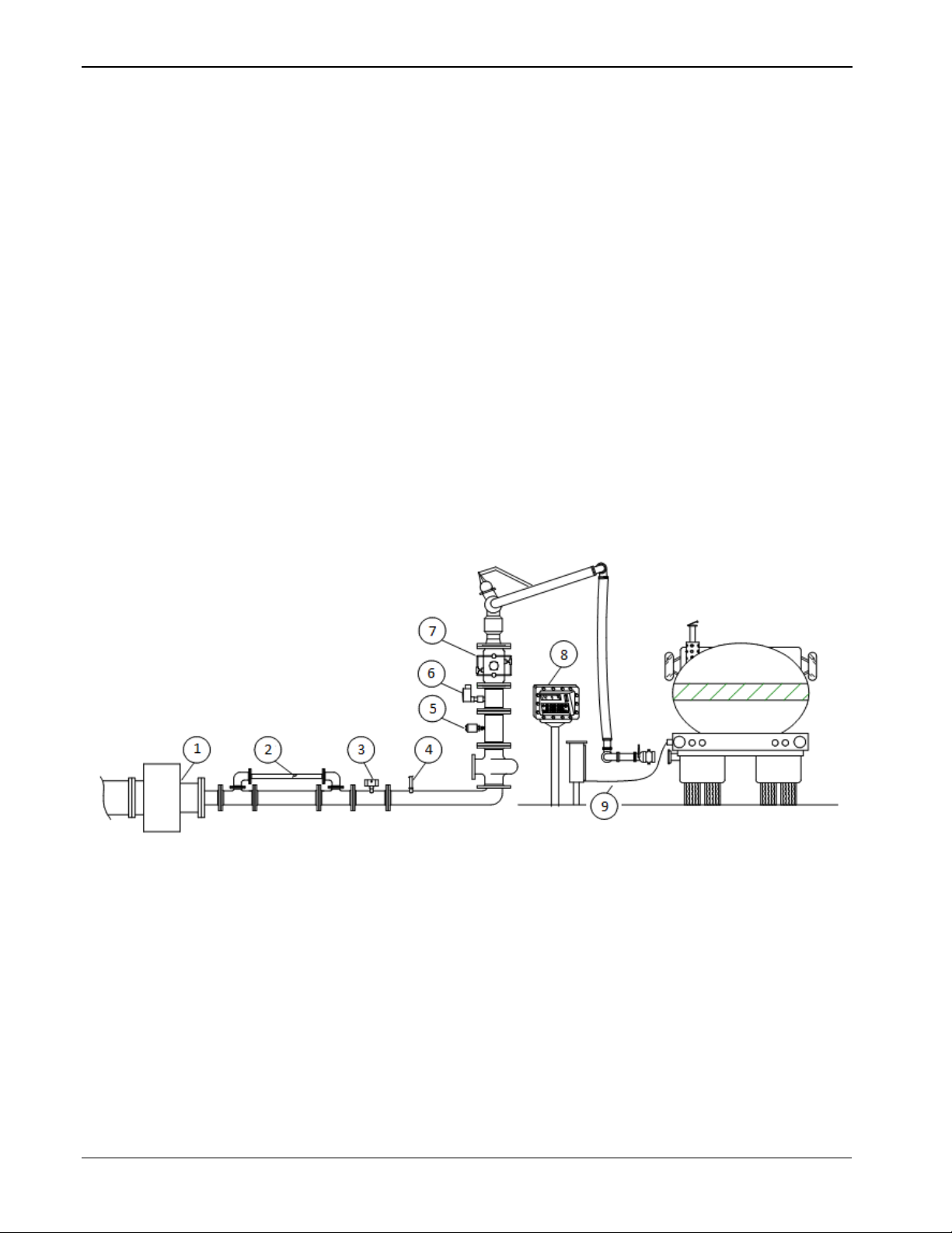
1: Pump Control Output
6. Temperature Probe
2
7
3
8
4
9
5. Meter Pulse Output
Electric motor driven pumps.
Motor operated block valves.
You can easily configure the DL8000 to deliver single component
liquids or to blend up to four liquid components in precise ratios, with
or without additive injection. Operator-selectable predefined delivery
control procedures (“recipes”) control the DL8000’s various possible
delivery and blending functions. Additive injection is controlled by
manual selection, recipe selection, or automatic selection from a
terminal automation system. These features allow one DL8000 and the
associated liquid delivery equipment to deliver many different
combinations of liquid products, based on requirements of the client or
receiver of the delivered product.
One common DL8000 application is to function as an on-site controller
for delivering refined liquid hydrocarbon products from loading
terminal storage tanks to mobile tanks (such as tanker trucks, rail cars,
or barges). Other applications include liquid component blending and /
or additive injection in refinery or chemical plant processes. In addition,
liquid components (with or without additive injection) can be blended
into flowing pipelines or into storage tanks. Figure 1-1 shows a typical
load rack installation with a DL8000 and associated equipment.
1-2 Overview Revised April 2020
. Density Transmitter
. Pressure Transmitter
. Additive Injection Output(s)
. Valve Control
. DL8000
. Permissive Contacts
Figure 1-1. Typical DL8000 Load Rack
Page 9

DL8000 Preset Instruction Manual
this product.
Factory Default
The DL8000 is factory-configured with a basic set of communication
Logical Functions
The flow measurement and logical functions listed below are available
Warning
Configuration
Overfill protection is critica lly important to your site. If your site DOES
NOT have overfill protection hardware installed, DO NOT set the
Overrun Limit Quantity value (defined on the Alarm Setup tab of the
Preset Setup screen in the Batching program) to zero. Setting that field
to zero DISABLES overfill protection. Remote Automation Solutions is
not responsible for damage resulting from disabling this critical safety
feature.
Additionally, you MUST have a redundant safe ty system (such as
Ground fault, Overfill) in place and operational. Otherwise, DO NOT use
and I/O modules to accommodate process I/O signals.
The default I/O module load—as well as any optional modules—is
determined during initial purchase. However, the I/O modules and
communications modules mix is field-reconfigurable, within the limits
of the DL8000’s central processing unit (CPU). The hardware
configuration determines the DL8000’s capacities for I/O signal
handling and the data logging/data communications.
in all hardware configurations of the DL8000. However, each unique
installation requires a specific complement of I/O modules, based on
the actual devices the DL8000 monitors and controls.
1.2 Hardware
1.2.1 Housing
The DL8000 can simultaneously monitor and control operation of up to
three flow meters, up to three flow control valves, and deliver up to four
products. The minimum configuration consists of one flow meter
measuring one component (liquid product), one control valve, one pump
start, and one permissive input. Product deliveries and component
blending deliveries are selected by up to 30 configurable recipes (batch
delivery/blending control procedures). The actual implementation of the
various possible process operations are covered in detail in other
sections of this manual.
The DL8000 has two primary physical components: the external
housing and the internal electronics. Refer to Chapter 2, Installation
and Use, for details on installation.
The DL8000 uses either of two external housings:
A cast aluminum casing with stainless steel front cover bolts. It is
flame-proof (in accordance with Class I, Zone 1, Group IIB) and
weatherproof (in accordance with IP66).
A 14-gauge stainless steel box with 12-gauge stainless steel
mounting flanges, CSA-rated as a Type 4 enclosure. The door is
Revised April 2020 Overview 1-3
Page 10
DL8000 Preset Instruction Manual
B
D
B
D
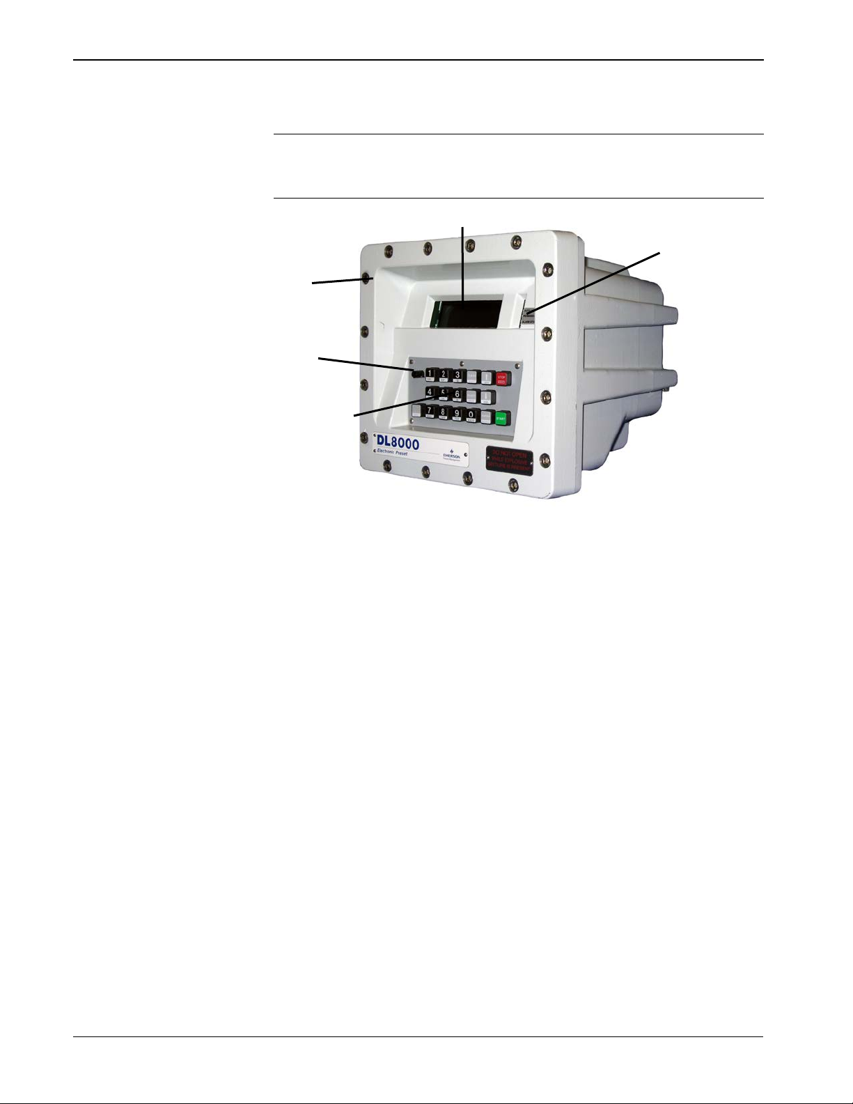
Note: For specific details, refer to the technical specification DL8000
made of 0.090 inch thick aluminum secured to the box with a
stainless steel piano hinge and two stainless steel spring latches.
Preset (part D301255X012), available at
www.EmersonProcess.com/Remote.
A Front cover bolts
Display
C Status LEDs
Weights & Measures switch
E Operator keypad
Figure 1-2. DL8000 (in Class I, Zone 1 Enclosure)
Sixteen stainless steel front cover bolts (M10 – 1.5 metric) secure the lid
to the housing. Two of the front bolts are longer and drilled close to the
threaded ends, allowing placement of Weight & Measures seal wires to
prevent undetected access to the electronics.
Bolt holes are tapped to 13 mm (0.50 inches); require an 8 mm (5/16inch) Allen wrench, and torque to 24 to 29 Newton/meters (18 to 21
foot/pounds) of force.
The operator keypad provides 18 rugged, Hall-Effect pushkeys which
are impervious to chemicals commonly associated with petroleum
applications. A sealable Weights & Measures switch provides security
to flow measurement parameters.
Secured behind non-glare glass, the liquid crystal display (LCD)
provides an 8-line by 40-column message area for operator interface.
The display uses a photo sensor and temperature sensor which can be
1-4 Overview Revised April 2020
Page 11

set to automatically adjust contrast and backlighting for optimal
viewing.
Light-emitting diodes (LEDs) displaying the status of alarms, operating
mode, and permissive powers are located to the right of the display.
With the front cover bolts removed, the lid hinges down to reveal the
electronic compartmen t.
1.2.2 Electronics
The DL8000’s CPU sits inside the cast aluminum enclosure. The
DL8000 uses a highly innovative and versatile CPU with a backplane to
which the CPU, Power Input module, input/output (I/O) modules, and
communication modules connect. The DL8000 unit has nine module
slots, three of which (slots 1, 2, and 3) can house communication
modules.
The DL8000 uses a 12 volt dc Power Input module to convert 120 to
250 V ac external input power to the voltage levels required by the
unit’s electronics and to monitor voltage levels to ensure proper
operation. For more information on the Power Input module, refer to
Chapter 3, Modules.
DL8000 Preset Instruction Manual
The DL8000 supports a number of I/O modules, which can satisfy a
wide variety of field I/O requirements (refer to Chapter 3, Modules). I/ O
modules include:
Analog Inputs (AI).
Analog Outputs (AO).
Discrete Inputs (DI).
Discrete Outputs (DO).
Digital Output Relay (DOR).
Alternating Current Input/Output (ACIO).
Advance Pulse Module (APM).
Pulse Inputs (PI) – High/Low Speed.
Resistance Temperature Detector Inputs (RTD).
Thermocouple (TC)
HART®
In addition to the built-in serial interface (the Local Operator Interface,
or LOI) and an Ethernet connection, the DL8000 also supports the
following communications modules:
EIA-232 Serial Communications.
EIA-422/485 Serial Communications.
Dial-up Modem.
Revised April 2020 Overview 1-5
Page 12

DL8000 Preset Instruction Manual
1.3 Security Gateway
For enhanced data security when using an IP/Ethernet connection,
Remote Automation Solutions recommends adding an industrial router
with VPN and firewall security. Recommended solutions include the
MOXA EDR-810, the Hirschman Eagle One, or the Phoenix mGuard
rs4000 (or equivalents). An example of how to install one of these
devices to the RTU/flow computer can be found in the Remote
Automation Solutions MOXA® Industrial Secure Router Installation
Guide (part number D301766X012). For further information, contact
your Local Business Partner or the individual vendor’s website.
1.4 Additional Technical Specifications
For further technical information on the DL8000, refer to the technical
specification DL8000 Preset (part D301255X012), available at
www.EmersonProcess.com/Remote.
1-6 Overview Revised April 2020
Page 13

Chapter 2 – 0BInstallation and Use
In This Chapter
2.1 Housing.………………………………………………………………………. 2-1
2.1.1 Class I Zone 1 Housing .............................................................. 2-2
2.1.2 Securing the Cover to the Class I Zone I Case .......................... 2-4
2.1.3 Class I Div 2 Housing ................................................................. 2-5
2.2 Card Cage.…………………………………………………………………… 2-6
2.2.1 Backplane ................................................................................... 2-7
2.3 Central Processor Unit (CPU)………………………………………………. 2-8
2.3.1 BInstalling and Removing Wire Channel Covers...................... 2-10
2.3.2 Removing and Installing Module Covers .................................. 2-11
2.3.3 Rem oving the CPU Mo dul e ...................................................... 2-11
2.3.4 Installing the CPU Module ........................................................ 2-12
2.4 License Keys ……………………………………………………………….. 2-12
2.4.1 Installing a License Key ............................................................ 2-13
2.4.2 Rem oving a Licens e Key .......................................................... 2-14
2.5 Installation Planning ……………………………………………………….. 2-15
2.6 Mechanical Installation ……………………………………………………. 2-15
2.6.1 Planning Considerations ........................................................... 2-16
2.7 Electrical Installation ………………………………………………………. 2-18
2.7.1 General Considerations ............................................................ 2-18
2.7.2 Field Wiring Installation Guidelines: ......................................... 2-18
2.7.3 Electrical Wire and Cable Selection and Installation ................ 2-19
2.7.4 Input/Output Field Signal Wiring ............................................... 2-20
2.7.5 Electrical Grounds .................................................................... 2-20
2.7.6 Wire Conduit Selection and Installation .................................... 2-22
2.8 Operator Interface …………………………………………………………. 2-23
2.8.1 Keypad ...................................................................................... 2-24
2.8.2 LED Status Indicators ............................................................... 2-25
DL8000 Preset Instruction Manual
This chapter describes the DL8000’s external housing, its internal
electronic components (the ROC800-Series CPU), and the specifics of
mechanical and electrical installation.
2.1 1BHousing
The DL8000 uses either of two external housings:
A cast aluminum casing with stainless steel front cover bolts. It is
flame-proof (in accordance with Class I, Zone 1, Group IIB) and
weatherproof (in accordance with IP66).
A 14-gauge stainless steel box with 12-gauge stainless steel
mounting flanges, CSA-rated as a Type 4 enclosure. The door is
made of 0.090 inch thick aluminum secured to the box with a
stainless steel piano hinge and two stainless steel spring latches.
Revised April 2020 Installation and Use 2-1
Page 14
DL8000 Preset Instruction Manual
2.1.1 9BClass I Zone 1 Housing
The DL8000 Class I Zone 1 housing is cast aluminum that, when
appropriately sealed, provides a flame-proof enclosure. Sixteen threaded
stainless steel fasteners secure the lower portion of the housing to the
hinged lid, which contains the display panel, operator keypad, and LED
status display. See Figures 2-1 and 2-2.
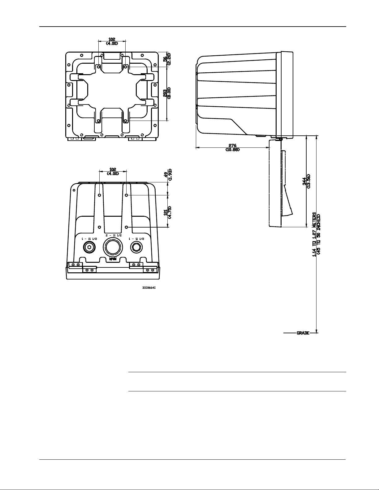
Figure 2-1. Standard DL8000 Enclosure
2-2 Installation and Use Revised April 2020
Page 15
DL8000 Preset Instruction Manual
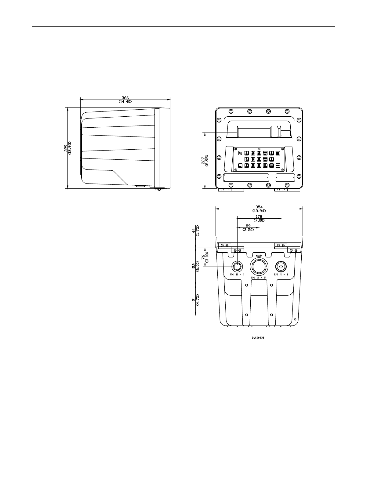
Figure 2-2. Standard DL8000 Enclosure
Note: The four mounting holes on the bottom and back of the DL8000
case accept 10M (10mm) bolts.
The DL8000’s design makes it highly adaptable to a wide variety of
installations. Consequently, this manual cannot cover all possible
installation scenarios. Contact your local sales representative if you
require information concerning a specific installation not described in
this manual.
Revised April 2020 Installation and Use 2-3
Page 16
DL8000 Preset Instruction Manual
clean and free of damage.
Planning is essential to a good installation. Because installation
requirements depend on many factors (such as the application, location,
ground conditions, climate, and accessibility), this document only
provides generalized guidelines.
2.1.2 10BSecuring the Cover to the Class I Zone I Case
The DL8000 ships from the factory with the cover secured to the case
with one stainless steel fastener (“bolt”). The remaining bolts are
bagged and included with the DL8000. You must install all bolts.
Warning
Caution
Failure to install ALL cover bolts will compromise the flame-proof
characteristics of the enclosure.
The flanges between the case and the cover create a flameproof joint.
Before you secure the cover to the case, make sure the surfaces are
To secure the DL8000 cover:
Caution
Notes:
You must use a torque wrench for this procedure.
The bolt in position 9 (see Figure 2-3) is factory-installed. Be sure
that the bolts you install in positions 12 and 8 are the two longer
bolts with pre-drilled holes (for the Weights & Measures seal wires).
1. Swing the DL8000 cover up against the case.
2. Insert a bolt in position 1 (refer to Figure 2-3) and finger-tighten the
bolt until you feel resistance.
3. Insert a bolt in position 2 (refer to Figure 2-3) and finger-tighten the
bolt until you feel resistance.
4. Repeat step 3 for bolts in positions 3 through 16.
5. Using a torque wrench, tighten the bolt in position 1 to
specifications (24 to 29 Newton/meters or 18 to 21 foot/pounds of
force).
6. Tighten bolts in positions 2 through 16 to specifications.
Tighten the bolts in the numeric order shown in Figure 3-3 to prevent
deforming the cover and risking the integr ity of the seal between cover
and case. You must install all the bolts.
2-4 Installation and Use Revised April 2020
Page 17

Figure 2-3. Bolt Tightening Sequence
8
2
11
15
1
5
9
13 7 12
16 3 6
10
14
2.1.3 11BClass I Div 2 Housing
DL8000 Preset Instruction Manual
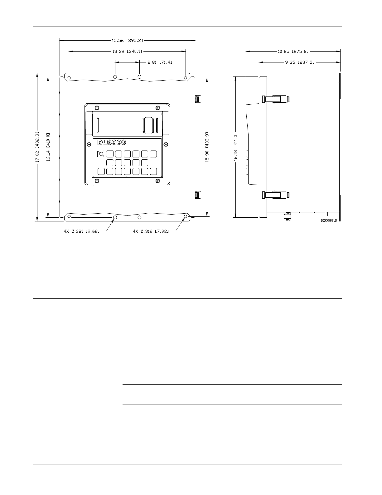
The Class I, Division 2 housing includes a 14-gauge stainless steel box
with 12-gauge stainless steel mounting flanges. The door is made of
.090 inch thick aluminum and is secured to the box via a stainless steel
piano hinge and two stainless steel spring latches. The latches include
features for padlocking or installing wire seals. The assembly includes a
door stop that locks the door in position at approximately 120 degrees
from the closed position. The viewing window in the enclosure door is
made from scratch / UV resistant polycarbonate/acrylic blend
(PC/PMMA). The keypad bezel is mounted to the front of the door and
is made from UV resistant polycarbonate. The assembly is rated by
CSA as a Type 4 enclosure, and can be either pole-mounted or flushmounted.
Revised April 2020 Installation and Use 2-5
Page 18
DL8000 Preset Instruction Manual
2.2 2BCard Cage
Figure 2-4. Class I Division 2 DL8000 Housing
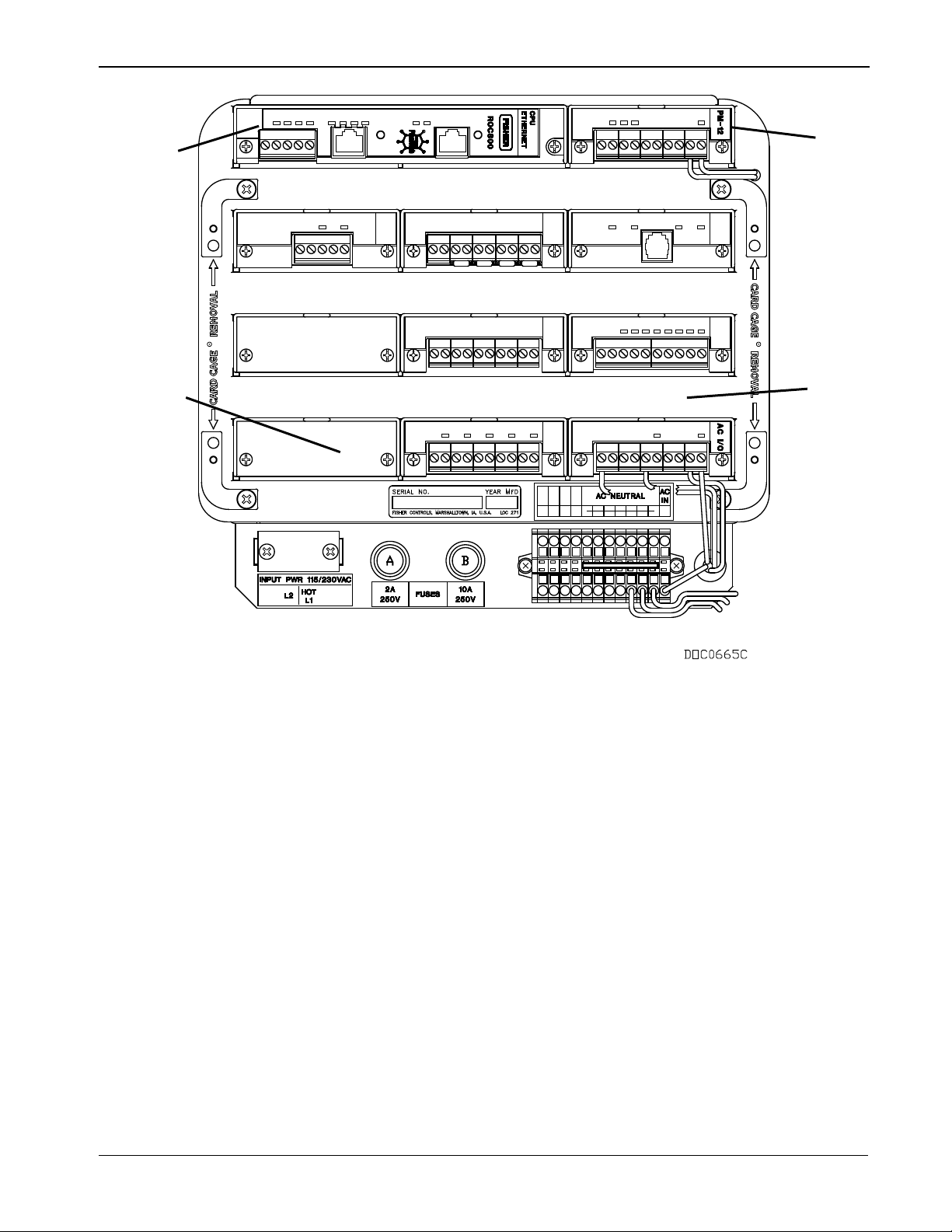
The DL8000 uses electronic modules which fit into a card cage. The
card cage rests inside the cast housing. See Figure 2-5 for a view of the
card cage as it would appear when the housing is opened.
The card cage provides a backplane with sockets for installing a main
processor board, a DC power supply, up to nine process I/O boards, and
up to three communications cards. The card cage (see Figure 2-5)
supports a total of nine boards, in addition to the power supply and the
CPU.
Note: Board placement is critical for I/O assignments during startup.
Refer to Chapter 3, Modules, for further information.
2-6 Installation and Use Revised April 2020
Page 19
DL8000 Preset Instruction Manual
A
B
C
C
A
B
D
2.2.1 12BBackplane
The backplane has connectors for the CPU, the power input module, and
all the I/O and communication modules. When a module is completely
inserted into the module slot, the connector on the module fits into one
of the connectors on the backplane. The backplane does not require any
wiring, and there are no jumpers associated with the backplane.
Removing the backplane from the housing is not recommended, as there
are no field-serviceable parts. If the backplane requires maintenance,
please contact your local sales representative.
CPU
Power module
Module cover
D Wire channel covers (removed)
Figure 2-5. Card Cage (with modules)
Revised April 2020 Installation and Use 2-7
Page 20
DL8000 Preset Instruction Manual
A
Securing screw
B
C
E
Ethernet port
F
B C D
E
F
A
A
A A B
C
D E F
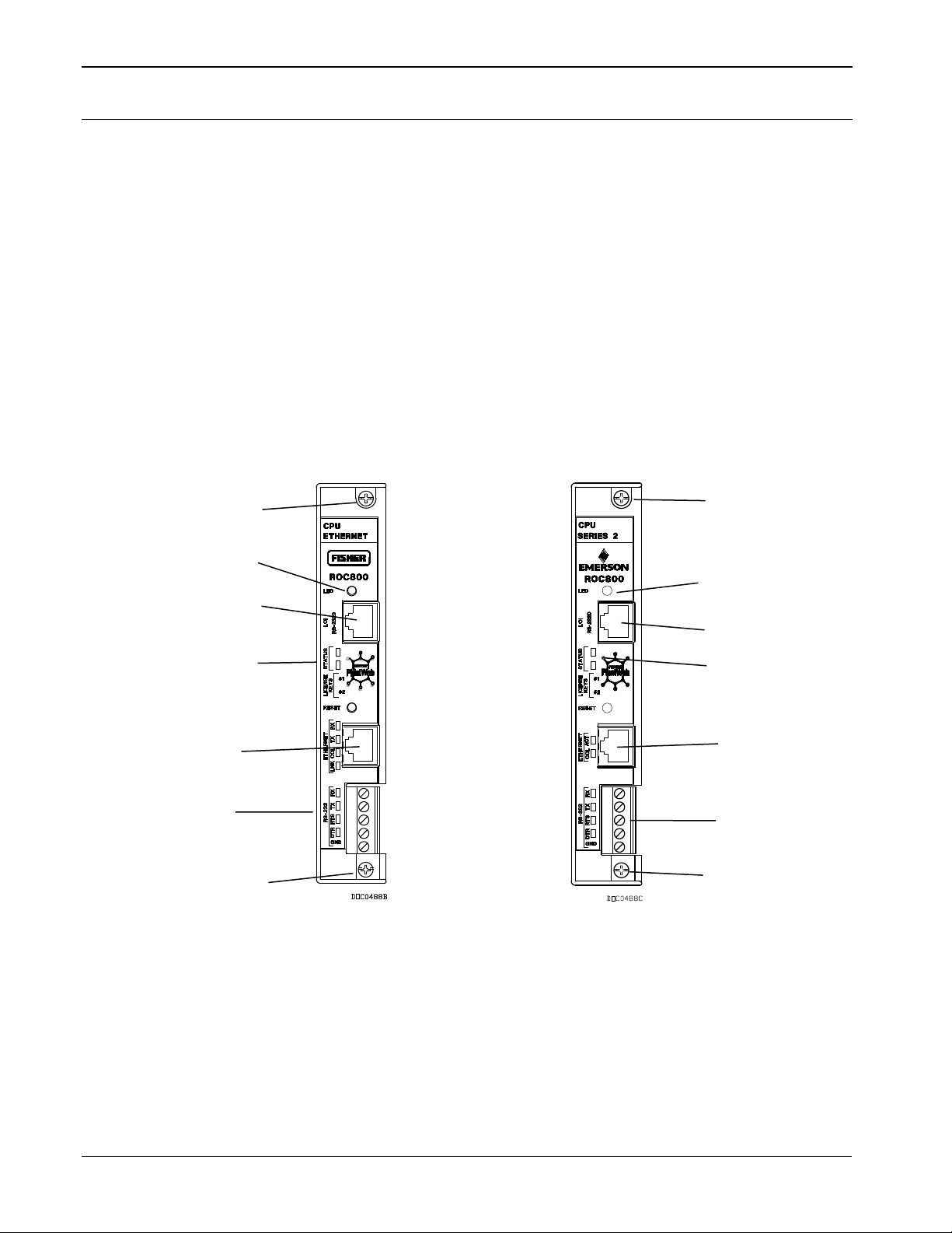
2.3 3BCentral Processor Unit (CPU)
The CPU contains the microprocessor, the firmware, connectors to the
backplane, three built-in communication ports (two with LEDs), a LED
low power wakeup button, a RESET button, the application license key
connectors, a STATUS LED indicating system integrity, and the main
processor. See Figure 2-6.
The 32-bit microprocessor is based on a Motorola® MPC862 Quad
Integrated Communications Controller (PowerQUICC™) PowerPC®
processor running at 65 MHz (in the Series 2 CPU module) or 50 MHz
(in the Series 1 CPU module).
The internal Sanyo 3 volt CR2430 lithium backup battery provides
backup of the data and the Real-Time Clock when the main power is not
connected.
Series 1 CPU Faceplate
(Gray)
Series 2 CPU Faceplate
(Black)
2-8 Installation and Use Revised April 2020
LED button
LOI – EIA-232 (RS-232D)
D Status LED
EIA0232 (RS0232C)
Figure 2-6. CPU Front View (Series 1 and Series 2 CPU Modules)
Page 21
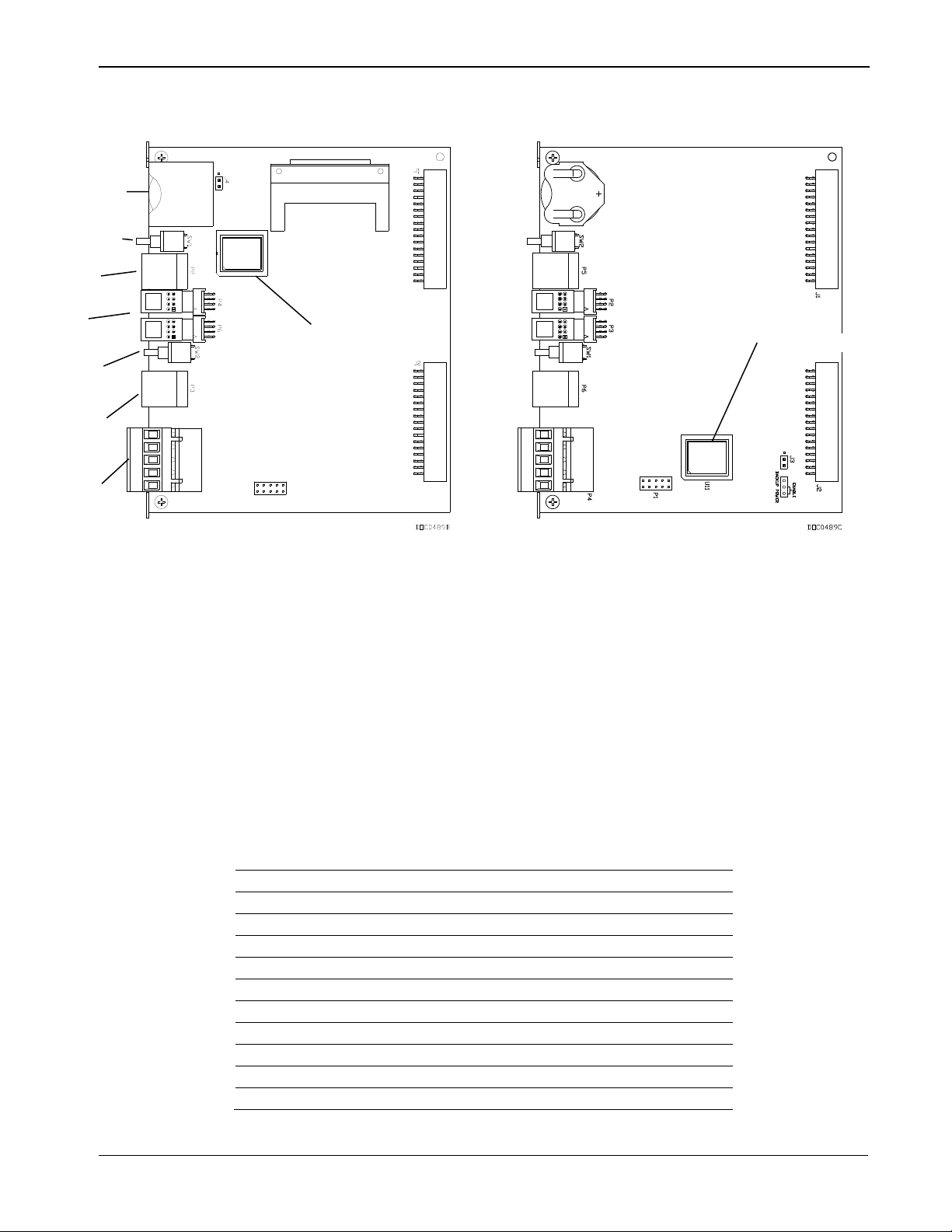
DL8000 Preset Instruction Manual
A
C
D
E
G
CPU Number
Series 1
Series 2
J1
Backplane connector
Backplane connector
J2
Backplane connector
Backplane connector
J3
Not Used
Battery Backup
J4
Battery Backup
Not Used
P2
LOI Port RJ-45
License Key Terminal
P3
Ethernet RJ-45
License Key Terminal
P4
License Key Terminal
RS-232
P5
Not Used
LOI Port RJ-45
P6
License Key Terminal
Ethernet RJ-45
SW1
LED Button
RESET Button
SW2
RESET Button
LED Button
A
B
D
E
C
H
H
F
G
Series 1 CPU (Green) Series 2 CPU (Black)
Battery
B LED Button
RJ-45 port
License keys
RESET button
F RJ-45 port
RS-232 port
H Microprocessor
Figure 2-7. CPU Connectors
Table 2-1. CPU Connector Locations
Revised April 2020 Installation and Use 2-9
Page 22

DL8000 Preset Instruction Manual
Status LED
Color
Definitions
Solution
Continually Lit
Green
DL8000 functioning normally.
N/A
Low Battery Voltage alert.
Charge battery.
System AI (Point number 1) LoLo Alarm.
Apply DC voltage source.
Flashing
Green
Firmware invalid.
Update firmware.
Green-Green
to Red-Red
Flashing
Green to Red
Firmware update is flashing image.
Do not restart the DL8000.
The CPU contains a microprocessor supervisory circuit. This device
monitors the battery voltage, resets the processor, and disables the
SRAM chip if the voltage goes out of tolerance. The CPU has an
internal Analog to Digital Converter (A/D). The A/D monitors the
supply voltage and board temperature. The CPU has two buttons (see
Figure 2-7):
LED – Press to turn on the LEDs on the CPU module, I/O modules,
RESET – Press to reset the DL8000 system to defaults.
The STATUS LED indicates the integrity of the DL8000. Refer to
Table 2-2.
Continually Lit Red
and communication modules when the DL8000 has timed out.
Table 2-2. STATUS LED Functions
Flashing
Firmware update in decompr ess ion. Do not restart the DL8000.
As a power-saving feature, you can enable or disable the LEDs on the
DL8000 (with the exception of the LED on the power module). You can
also use the ROCLINK™ 800 software to configure how long the LEDs
remains on after the LED button on the CPU module is pressed. For
instance, with the default setting of five minutes, all LEDs go off after
five minutes. If you press the LED button, LEDs become active again
for five minutes. If you enter a 0 (zero) setting, they always stay active.
2.3.1 13BInstalling and Re m ovi ng Wire Channel Covers
The DL8000 includes wire channel covers (see Figure 2-5) you install
over the wiring channels once you complete wiring the terminal blocks
on the modules.
To install a wire channel cover:
1. Align the wire channel cover over the wire channel, allowing
unobstructed wire access.
2-10 Installation and Use Revised April 2020
2. Press the wire channel cover into place until it snaps.
Note: The tabs on the top side of the wire channel cover should rest in
the slots on the top edge of the channel.
To remove a wire channel cover:
1. Grasp the wire channel cover at both the left and right ends.
Page 23
DL8000 Preset Instruction Manual
2. Start at the left or right and pull the wire channel cover out of the
wire channel.
2.3.2 14BRemoving and Installi ng Module Covers
Before you insert an I/O or communications module, remove the
module cover (see Figure 2-5) over the empty module slots in which
you intend to install the modules. Although you are not required to
remove the power to the DL8000 to perform this procedure, caution is
always advisable when working with a powered DL8000.
Caution
To avoid circuit damage when working inside the unit, use appropriate
electrostatic discharge precautions (such as wearing a grounded wrist
strap).
When working on units located in a hazardous area (where explosive
gases may be present), make sure the area is in a non-hazardous state
before performing procedures. Performing these procedures in a
hazardous area could result in personal i n jury or property damage.
To remove a module cover:
1. Remove the wire channel cover.
2. Unscrew the two captive screws on the face of the cover.
3. Using the tab at the top side of the module cover, lift the module
cover from the DL8000.
Note: If you remove a module for an extended period, install a module
cover over the empty module slot to keep dust and other matter
from getting into the DL8000.
To install a module cover:
1. Place the module cover over the module slot.
2. Tighten the two captive screws on the face of the cover.
3. Replace the wire channel cover.
2.3.3 15BRemoving the CPU Module
To remove the CPU module:
Caution
Failure to exercise proper electrostatic discharge precautions (such as
wearing a grounded wrist strap) may reset the processor or damage
electronic components, resulting in interrupted operations.
When working on units located in a hazardous area (where explosive
gases may be present), make sure the area is in a non-hazardous state
before performing procedures. Performing these procedures in a
hazardous area could result in personal i n jury or property damage.
1. Back up critical data.
Revised April 2020 Installation and Use 2-11
Page 24

DL8000 Preset Instruction Manual
hazardous area could result in personal i n jury or property damage.
Note: “Critical” data may include your device configuration file,
2. Remove power from the DL8000.
3. Remove the wire channel cover.
4. Unscrew the two captive screws on the front of the CPU module and
5. Place a small screwdriver under the ejector clip at the left or right of
6. Remove the CPU module carefully. Make sure not to pull on any
2.3.4 16BInstalling the CPU Module
To install the CPU module:
Caution
Failure to exercise proper electrostatic discharge precautions (such as
wearing a grounded wrist strap) may reset the processor or damage
electronic components, resulting in interrupted operations.
When working on units located in a hazardous area (where explosive
gases may be present), make sure the area is in a non-hazardous state
before performing procedures. Performing these procedures in a
device alarms and events history, or displays.
remove the faceplate.
the CPU module and lightly pry the CPU module out of its socket.
You may find it easiest to carefully pry on the left ejector clip a
little, and then carefully pry the right ejector. You will feel and hear
the CPU as it detaches from the backplane.
cables attached to the CPU module.
2.4 4BLicense Keys
1. Slide the CPU module into the slot.
2. Press the CPU firmly into the slot, ensuring the ejector clips rest on
the module rail guides. The connectors at the back of the CPU
module fit securely into the connectors on the backplane.
3. Place the CPU faceplate on the CPU.
4. Tighten the two captive screws on the faceplate of the CPU module
firmly.
5. Replace the wire channel cover.
6. Return power to the DL8000.
License keys with valid license codes grant access to applications or, in
some cases, allow optional firmware functionality to execute. In some
situations, a license key may also be required before you can run the
application. Examples of licensed applications include DS800
Development Suite software, meter run calculations, and various User C
programs (such as LiquidCalcs in this application). You can then
2-12 Installation and Use Revised April 2020
Page 25
DL8000 Preset Instruction Manual
Failure to exercise proper electrostatic discharge precautions (such as
hazardous area could result in personal i n jury or property damage.
configure these applications using ROCLINK 800 or the DS800
Development Suite software.
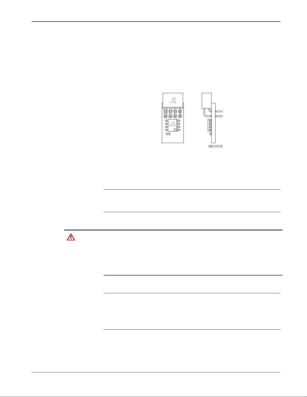
The term “license key” refers to the physical piece of hardware (see
Figure 2-8 and Figure 2-9) that can contain up to seven different
licenses. Each DL8000 can have none, one, or two installed license
keys. If you remove a license key after enabling an application, the
firmware disables the task from running. This prevents unauthorized
execution of protected applications in a DL8000.
Figure 2-8. License Key
2.4.1 17BInstalling a License Ke y
Note: For the DL8000, license keys are a factory-installed option.
Under normal operation, you should not need to install, remove,
or replace a license key.
To install a license key:
Caution
wearing a grounded wrist strap) may reset the processor or damage
electronic components, resulting in interrupted operations.
When working on units located in a hazardous area (where explosive
gases may be present), make sure the area is in a non-hazardous state
before performing procedures. Performing these procedures in a
1. Back up critical data.
Note: “Critical” data may include your device configuration file,
device alarms and events history, or displays. Refer to Saving
and Retrieving Configurations in the ROCLINK 800
Configuration Software User Manual (for DL8000) (part
D301259X012) for further information.
2. Remove power from the DL8000.
3. Remove the wire channel cover.
Revised April 2020 Installation and Use 2-13
4. Unscrew the captive screws from the CPU faceplate and remove it.
Page 26
DL8000 Preset Instruction Manual
hazardous area could result in personal i n jury or property damage.
5. Place the license key in the appropriate terminal slot in the CPU (see
Figure 2-9. License Key Installation
6. Press the license key into the terminal until it is firmly seated (refer
7. Reattach the CPU faceplate and tighten the two captive screws.
8. Replace the wire channel cover.
Figure 2-7).
Note: If you are installing a single license key, place it in the
uppermost slot (closest to the LOI port).
to Figure 2-9).
9. Restore power to the DL8000.
2.4.2 18BRemoving a License Key
To remove a license key:
Caution
Failure to exercise proper electrostatic discharge precautions (such as
wearing a grounded wrist strap) may reset the processor or damage
electronic components, resulting in interrupted operations.
When working on units located in a hazardous area (where explosive
gases may be present), make sure the area is in a non-hazardous state
before performing procedures. Performing these procedures in a
1. Back up critical data.
Note: “Critical” data may include your device configuration file,
device alarms and events history, or displays. Refer to Saving
and Retrieving Configurations in the ROCLINK 800
Configuration Software User Manual (for DL8000) (part
D301259X012) for further information.
2. Remove power from the DL8000.
3. Remove the wire channel cover.
4. Unscrew the two captive screws on the CPU faceplate and remove
it.
5. Remove the license key from the appropriate terminal slot in the
CPU (see Figure 2-9).
6. Reattach the CPU faceplate and tighten the two captive screws.
2-14 Installation and Use Revised April 2020
Page 27

7. Replace the wire channel cover.
8. Restore power to the DL8000.
2.5 5BInstallation Planning
Installation planning is very important due to the DL8000’s physical
and functional reconfigurable capabilities. Installation planning consists
of the following three major tasks.
Assure that the DL8000 contains the required number and type of
Determine the functions the DL8000 will perform. You selectively
Design the mechanical/electrical installation with special
DL8000 Preset Instruction Manual
process I/O boards to monitor and control the other devices in the
product delivery system.
enable these functions during the DL8000’s configuration
procedure.
consideration for both the operator’s safety and ease-of-use and the
maintenance technicians’ safety and ease-of-access to instruments
and devices.
2.6 6BMechanical Installation
In planning the physical installation of the DL8000, consider ease of use
of the instrument with the operator in a safe and comfortable position.
Also consider how maintenance tasks may be performed without
disrupting ongoing product delivery operations in close proximity.
Drawing rough diagrams of normal operator actions during the different
possible batch delivery related tasks may be helpful. Note especially the
operator’s location in relation to the location of one or two tanker
vehicles and their related loading arm and bottom loading hose
connections.
Some location or position restrictions may be present when a DL8000 is
retrofitted or upgraded into an existing installation. However,
mechanical installation planning should still be performed. It may be
possible to correct an existing inconvenient controller mounting location
in a current loading rack installation when retrofitting a DL8000 at the
installation.
Following are the major steps performed during installation.
1. Plan the installation.
2. Fabricate device supports and lay electrical conduit.
3. Mount the DL8000 and other load rack devices.
4. Run and connect all wiring.
5. Verify and tag each wire.
Revised April 2020 Installation and Use 2-15
Page 28

DL8000 Preset Instruction Manual
6. Seal conduit within 50 mm (2 inches) of the DL8000.
7. Secure cases and covers of all devices.
8. Apply electrical power.
9. Configure (set up) the DL8000 and any other devices as required.
10. Disable product block valves and additive block valves to
11. Enable one product block valve at a time and one additive
12. Perform meter proves to determine DL8000 meter calibration.
2.6.1 19BPlanning Considerations
Note: Install certified conduit plugs in any unused entries.
prevent any product or additive flow. Then verify system monitor
and control functions with dry piping.
injection system at a time. Then verify the piping integrity and
system operation in increments for each product and each additive
handling system.
Consider the following points during DL8000 mechanical installation
planning:
Maintenance Access
The operator panel is hinged at the bottom side and opens down for
maintenance access. Route all conduit to the rear, sides, or bottom of
the unit. Do not locate any object under the DL8000 or in front of
the conduit connections for a distance of approximately 533 mm (21
inches) below the instrument.
Mounting Height
Recommended mounting height is approximately 1.14 to 1.27
meters (45 to 50 inches) above grade to the bottom of the DL8000
case (see Figure 2-2). Mounting height determines the ease of
viewing the display panel and ease of use of the keypad.
Mounting Position
North/south/east/west orientation of the operator control panel is
somewhat predetermined by the loading facility design. Consider the
location of the operator in relation to one or two tanker vehicles
present and connected at the loading island.
Mounting Fixtures
You must fabricate mounting fixtures for the DL8000. Each
DL8000 comes with four M10-1.5 x 15 mm metric thread bolts for
mounting. You can either rear-mount or bottom-mount the DL8000,
although bottom-mounting is preferred due to the DL8000’s weight.
The mounting attachment should be a 4 mm (0.16 inch) (minimum)
thick mild steel member with four 11.5 mm (0.44 inch) diameter
2-16 Installation and Use Revised April 2020
Page 29

DL8000 Preset Instruction Manual
holes that match the bolting pattern being used. The steel member
may be sheet, angle, channel, or another shape.
Center the forward pair of mounting screw holes in bottom-mount
fixtures no more than 19 mm (0.75 inch) from the edge. The case
has a taper to the rear. The standard case may need a shim at the rear
pair of screws to level the DL8000. Level the case to allow for the
best conduit alignment.
Special Installation Considerations
The DL8000 is designed for installation in an outdoor environment.
The instrument is weatherproof and explosion-proof in accordance
with applicable standards. Some of the following installation
suggestions concerning environmental protection describe accepted
engineering practices and should not be considered to be limitations
on the utility of the instrument.
• If the loading rack or loading island area is covered, locate the
DL8000 so that the operator is protected or partially protected
from direct rainfall.
• In tropical climates, place sunshades above the DL8000 and
other electronic instruments, such as process transmitters. Locate
sunshades to prevent direct sunlight on the instruments during
the hottest part of the day (10:00 to 15:00). Construct sunshades
of metal, fiberglass, or other suitable materials. Sunshades
should be rear-sloping to direct rain to the rear of the instrument
and away from the operator. Avoid sharp edges or corners on
sunshades to prevent injuries.
• In desert areas or areas of blowing sand, install a cover to
protect the operator control panel during idle time. Continuous
blowing sand over an extended period of time can sandblast the
display panel and pushkey legends, affecting readability.
Fabricate a cover from raw materials or use a modified NEMA 4
weatherproof enclosure with a sealed rear cutout, placing it over
the operator panel. Use care in the design of any hinged cover so
that wind gusts do not move the cover and cause injuries. Any
cover design must allow for maintenance access to the DL8000.
The operator panel is hinged to open in the down direction for
maintenance access.
• In areas of continuous high humidity, place a 76.2mm x
76.2mm (3-inch x 3-inch) desiccant pack inside the DL8000
case. Place desiccant packs so that any expansion due to
moisture absorption does not interfere with any of the equipment
or wiring inside the case. Two sources of desiccant packs are:
o Waterguard® Desiccants
PO Box 1079
16023 I-10 East, Suite 30
Channelview, TX 77530
Revised April 2020 Installation and Use 2-17
Page 30

DL8000 Preset Instruction Manual
Seal all cable entries within 50 mm (2 inches) of the enclosure with
2.7 7BElectrical Installation
Caution
Shut off all sources of AC and DC power to the loading island site
before installing the DL8000.
2.7.1 20BGeneral Considerations
Use any of three cable entries located on the bottom of the housing for
wiring access to the DL8000.
A threaded 25.4 mm (1-inch) female NPSM connection on the left
side of the unit (for AC power and control / status signals).
A spare threaded 25.4 mm (1-inch) female NPSM connection on the
right side of the unit (may be used for meter pulse wiring to
segregate meter pulse wiring from all other signals).
o A+ Corporation
40462 Highway 42
Prarieville, LA 70769
A threaded 50 mm (2-inch) female NPSM connection for DC
cabling and low voltage level signals in the center.
Caution
suitable sealing or potting compound.
2.7.2 21BField Wiring Installation Guidelines:
Route external AC and DC wiring in separate conduits.
Record cable and wire routing and interconnection information to
simplify the creation of as-built documentation for the system.
Provide remote circuit breakers and optional disconnect switches for
all AC and DC power input circuits.
Follow power and signal field wiring grounding standards.
Use only stranded copper wire, equal to or of larger gauges as
indicated on the basic wiring diagrams located at the rear of this
section. Take care not to cut or weaken wire strands during the
removal of insulation.
Clearly mark all wire ends with slip-on wire tags or similar devices.
Preferably, color-code the wire tags to indicate the voltage level and
mark tags with the specific signal name.
Cut power and signal wires with an additional length of
approximately 50 mm (2 inches) for service loops to allow terminal
board and connector removal.
2-18 Installation and Use Revised April 2020
Page 31

DL8000 Preset Instruction Manual
Position all wiring within the unit to avoid unnecessary crimping
and overcrowding and to insure proper clearance for the instrument
door and hinges.
After completion, thoroughly check the wiring to insure that input
AC power and all field I/O signals are correctly connected at the
DL8000 terminations and at the terminations located on the
corresponding field device.
2.7.3 22BElectrical Wire and Cable Selection and Installation
All wiring must conform to the National Electrical Code; to local, state,
or other jurisdictions; and to company standards and practices.
Following are recommendations for 115/230 Volts ac power wiring:
Use multi-strand copper conductor wire and cable when connecting
the DL8000 to the power source and the field devices.
Ensure that all wire and cable is in new condition and adheres to the
manufacturer's quality standards with the size, type of insulation,
and voltage rating.
Use the following recommended wire types and sizes for AC power
input to the DL8000:
• Power feed should be 100 or 240 Volts ac, 50 to 60 Hertz, single
phase, three-wire. Locate a 15 Amp circuit breaker and
optionally a power disconnect switch in a safe area.
• Use wire size AWG 14 for power feed for distances up to 250
feet.
• Use wire size AWG 12 for power feed for distances of 250 to
500 feet.
• Use wire size AWG 10 for power feed for distances of 500 to
1000 feet.
Note: Power feed distances greater than 1000 feet are not
recommended.
• Single-conductor wiring must be THWN type, which is moisture
and heat-resistant thermoplastic with nylon jacket, approved for
dry-and-wet locations, and has a maximum operating
temperature of 75 degrees Celsius (167 degrees Fahrenheit). The
wire or cable jacket must contain the Underwriters Laboratories,
Inc. mark for Gasoline and Oil Resistant, II.
Ensure that shielded wires and cables for meter pulse signals have
shield-drain wires. The shield-drain wires must not be more than
two AWG sizes smaller than the conductors for the cable. The
shield-drain wire must be connected to ground at only one end of the
run.
Revised April 2020 Installation and Use 2-19
Page 32

DL8000 Preset Instruction Manual
Connect RS-485 serial data signals via two twisted pairs with
Use AWG 28 to AWG 18 RS-232 single ended serial data signals
Ensure that all cables have either Teflon® or PVC exterior jackets.
Install insulated wire and cable in accordance with the
Use suitable lubrication during wire pulls in conduit to prevent wire
Place cable or wire markers at the terminations of all cables and
overall shield, AWG 28 to AWG 22. Ideally, the capacitance should
not be greater than 16 pF per foot (Belden 9842 for example). The
use of a signal common (ground) conductor connected to each
device is a recommended option. Capacitance greater than 16 pF per
foot may be used at reduced baud rates and/or with shorter data
communication cable runs.
for cable lengths up to 15 meters (50 feet).
manufacturer's recommendation. Do not exceed maximum wire
tension, maximum insulation pressure, or minimum bending radius.
stress.
individual wires. Markers should contain the specific wire or cable
codes designated for that part icu lar circuit. The wire and cable
markers should be legible and permanent.
Check all wiring connected to the DL8000 for continuity, proper
size, and proper classification. Verify the source or destination of
each circuit before connecting to the DL8000 and related devices.
2.7.4 23BInput/Output Field Signa l Wiring
Following are recommendations for process signal wiring:
Use metal conduit for all process signal wiring.
Use separate conduits for AC and DC voltage circuits.
Ensure that all process signal wiring is a single, continuous length
between field devices and the DL8000, unless the length and/or
conduit runs require that multiple pulls be made. In these instances,
interconnect the individual conductors with suitable terminal blocks.
2.7.5 24BElectrical Grounds
Following are recommendations for electrical grounds:
A clamp type ground lug is located on the inside bottom front of the
case. Chassis ground conductors (color code green) inside the
DL8000 enclosure should be stranded, insulated, copper wire.
Connect these device chassis ground conductors to the clamp type
ground lug.
A clamp type ground lug is located on the outside of the case at the
rear of the lower right (facing the operator panel) casting rib.
2-20 Installation and Use Revised April 2020
Page 33

DL8000 Preset Instruction Manual
Connect this ground point to a copper ground rod as described
below.
• Connect a single-point ground (the outside case ground lug) to a
copper-clad, ten-foot long, 19 mm (0.75 inch) diameter steel rod,
which is buried, full-length, vertically, into the soil as close to
the equipment as is practical. (Grounding rod furnished by
others.)
Note: We recommend cad welding the wire to the rod to ensure
proper grounding.
• Resistance between the copper-clad steel ground rod and the
earth ground must not exceed 25 ohms. If necessary, additional
ground rods may be driven into the ground, while a spacing of
not less than 1.8 meters (6 feet) is used to separate each of the
ground rods. Additionally, the ground rods must be
interconnected with a continuous stranded wire, sized as
indicated below.
• When several DL8000 units are located in close proximity, each
single-point equipment ground must be inter-connected to the
single point grounds of the other DL8000s. These interenclosure equipment grounding connections must be “daisychained” so that only one point of the grounding daisy-chain is
connected to the actual ground rod.
Size the equipment-grounding conductors used between DL8000
units and the copper-clad steel ground rod or for inter-enclosure
equipment ground connections according to the following
specifications:
• Stranded, insulated, copper wire size AWG 8 for distances of
less than 4.5 meters (15 feet).
• Stranded, insulated, copper wire size AWG 6 for distances of 4.5
to 9 meters (15 to 30 feet).
• Stranded, insulated, copper wire size AWG 4 for distances of (9
to 30.5 meters (30 to 100 feet).
• All inter-enclosure equipment-grounding conductors should be
protected by metallic conduit.
• Shield-drain wires should be connected to ground at only one
end of the shielded conductor run.
• External equipment (such as data printers or terminal automation
systems which are connected to the DL8000) should be powered
via isolation transformers to minimize the ground loops caused
by the internally shared safety and chassis grounds.
Revised April 2020 Installation and Use 2-21
Page 34

DL8000 Preset Instruction Manual
2.7.6 25BWire Conduit Selection and Installation
Following are recommendations for conduit installation:
Ensure that all conduit and the associated assembly and installation
Ensure that all conduit runs have an explosion-proof sealing
Ensure that the conduit installation is vapor tight, with threaded hub
Square all conduit cutoffs. Cutoffs must be made by a cold cutting
Coat all conduit fitting threads, including factory-cut threads, with a
materials used for the installation of the DL8000 are in new
condition and adhere to the manufacturer's quality standards.
(potting) fitting located within 50 mm (2 inches) distance from the
conduit entrance to the DL8000.
fittings, sealed conduit joints and gaskets on covers, or other
approved vapor-tight conduit fittings.
tool, hacksaw, or by some other approved means that does not
deform the conduit ends or leave sharp edges.
metal-bearing conducting grease (such as Crouse-Hinds STL or
equivalent) prior to assembly.
Temporarily cap the ends of all conduit runs immediately after
installation to prevent accumulation of water, dirt, or other
contaminants. Swab out conduits prior to installing the conductors.
Where applicable, install explosion-proof seals in the conduit.
Install drain fittings at the lowest point in the conduit run and install
seals at the point of entry to the DL8000 to prevent vapor passage
and accumulation of moisture.
Use liquid tight conduit fittings (such as Myers Scru-tite® or
equivalent) for conduit which is exposed to moisture.
2-22 Installation and Use Revised April 2020
Page 35
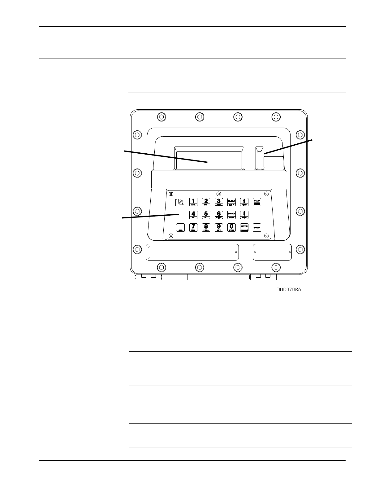
2.8 8BOperator Interface
Component
Use
A
C
B
Note: Refer to Appendix E, DL8000 Keypad Display, in this manual
The DL8000’s keypad display has the following parts:
DL8000 Preset Instruction Manual
for a complete discussion of the features and functionalities of
the DL8000 keypad display.
A: Display
B: LED Status Indicators
C: Keypad
Figure 2-10. DL8000 Operator Interface
Keypad
Display
LED Status Indicators
Revised April 2020 Installation and Use 2-23
Enables the operator to select recipes, enter the
desired quantity, and control batch deliveries.
Note: With appropriate authority, the operator can
also program the DL8000.
A liquid crystal display (LCD) panel divided into two
sections (right and left). Each section provides
eight lines of up to 40 characters in widt h . The
display and keypad provide the primary method for
operating the DL8000.
Three light-emitting diodes (LEDs) display through
the vertical window to the right of the LCD,
indicating the DL8000’s operational status.
Page 36

DL8000 Preset Instruction Manual
Key
Function
0 through 9
Provide numeric digits for data entry.
are currently not supported.
ENTER/PROGRAM
Accept the manually entered value and continue.
supported.
CLEAR/EXIT
Reject the manually entered value and continue.
ALT+EXIT leaves the display.
SELECT/BKSP
Toggle the On/Off option for each defined additive.
back one character at a time.
Scroll down or move the select box to the next item
ALT+ moves to the next display.
Scroll up or move the select box to the previous item
ALT+ moves to the next display.
START
Initiate the batch loading operation after batch setup
data has been entered.
STOP/PRINT
Stop the batch loading operation.
supported.
ALT
Enable alternative functions on selected keys.
A
2.8.1 26BKeypad
The DL8000 keypad enables the operator to select recipes, enter the
desired preset quantity, control batch deliveries, and (with appropriate
authority) program the DL8000. See Figure 2-11.
A: Weights & Measures Switch
Figure 2-11. DL8000 Keypad
/
/
ALT+3 increases the brightness of the display;
ALT+6 decreases the brightness of the display.
Note: The alphabetic values on the numeric keys
Note: The ALT+PROGRAM function is not currently
ALT+BKSP (Backspace) moves the cursor position
in the Recipes Selection display.
in the Recipes Selection display.
2-24 Installation and Use Revised April 2020
Note: The ALT+PRINT function is not currently
Page 37

Note: The Weights & Measures switch, located in the left upper corner
LED
Mode
Status
Function
YELLOW
Manual
Off
DL8000 is operating in Manual mode.
Manual or Auto mode.
Auto
On
DL8000 is operating in Auto mode (linked to a
host computer and operating as a slave unit.
Flashing
Two short pulses each second: case
situation.
GREEN
Permissive Power
On
The permissive power circuit is closed (the
supply) and is not programmable.
Off
The permissive power circuit is open. This
supply) and is not programmable.
RED
Alarm Status
On
A primary (or critical) alarm is active. You must
batch or new transaction.
Off
All alarms are inactive.
Flashing
A secondary (non-critical) alarm is active.
of the keypad, is lockable and wire-sealable to restrict access to
the flow calculations.
2.8.2 27BLED Status Indicators
The yellow, red, and green LEDs (see Figure 2-10) provide information
about the DL8000’s operational status.
DL8000 Preset Instruction Manual
Note: Local operation is identical in either
internal temperature is too high, the
keypad/display is disconnected, or power is
removed from the keypad/display.
One short pulse every two seconds:
Condition that caused the alarm has
returned to normal. Power up the DL8000 or
reset to continue using the keypad/display.
Rapid flashing: Power failure or low power
normal state when a batch delivery is in
progress).
Note: The green LED indicator’s function
depends on the state of the permissive
circuit (which is located in the power
indicates an abnormal state which is due to
permissive power failure or failure of one or
more permissive circuits wired in series (wired
AND) with the permissive power source
Note: The green LED indicator’s function
depends on the state of the permissive
circuit (which is located in the power
clear this alarm before you can begin a new
Revised April 2020 Installation and Use 2-25
Page 38

DL8000 Preset Instruction Manual
This page is intentionally left blank.
2-26 Installation and Use Revised April 2020
Page 39

Chapter 3 – Modules
In This Chapter
3.1 Power Input Module ............................................................................... 3-1
3.1.1 12 Volt DC Power Input Module ............................................... 3-2
3.2 Input/Output Modules ............................................................................ 3-3
3.2.1 General Installation ................................................................... 3-5
3.2.2 Installing an I/O Module ............................................................ 3-6
3.2.3 Removing an I/O Module .......................................................... 3-7
3.2.4 Wiring I/O Modules ................................................................... 3-7
3.2.5 Analog Input (AI) Modules ........................................................ 3-7
3.2.6 Analog Output (AO) Modules.................................................... 3-9
3.2.7 Discrete Input (DI) Modules .................................................... 3-10
3.2.8 Pulse Input (PI) Modules ........................................................ 3-12
3.2.9 Discrete Output (DO) Modules ............................................... 3-14
3.2.10 Discrete Output Relay (DOR) Modules .................................. 3-15
3.2.11 Resistance Temperature Detector (RTD) Input Modules ....... 3-17
3.2.12 Alternating Current Input/Output (AC I/O) Module ................. 3-18
3.2.13 Advance Pulse Module (APM) ................................................ 3-23
3.2.14 Thermocouple (TC) Input Module ........................................... 3-27
3.2.15 HART® Module ....................................................................... 3-30
3.3 Communication Modules and Ports ..................................................... 3-32
3.3.1 Wiring Communications .......................................................... 3-34
3.3.2 Local Operator Interface (LOI – Local Port) ........................... 3-35
3.3.3 Using the LOI .......................................................................... 3-36
3.3.4 Ethernet Communications ...................................................... 3-36
3.3.5 EIA-232 (RS-232) Serial Communications ............................. 3-38
3.3.6 EIA-422/485 (RS-422/485) Serial Communications
3.3.7 EIA-422/485 (RS-422/485) Jumpers & Termination
3.3.8 Dial-up Modem Communications Module ............................... 3-41
3.4 Additional Technical Information.......................................................... 3-43
DL8000 Preset Instruction Manual
Module .................................................................................... 3-39
Resistors ................................................................................. 3-40
This chapter describes the various power, input/output, and
communications modules the DL8000 uses. It also describes how to
install, remove, and wire the modules.
3.1 Power Input Module
The DL8000 uses a Power Input module to convert the voltage from the
AC power supply to the voltage levels the DL8000 unit’s electronics
require and to monitor voltage levels to ensure proper operation. All
DL8000 applications use the 12 volt Power Input module.
The Power Input module has removable terminal blocks for wiring and
servicing. The terminal blocks can accept wire sizes between 12 and 22
AWG (American Wire Gauge).
Revised April 2020 Modules 3-1
Page 40
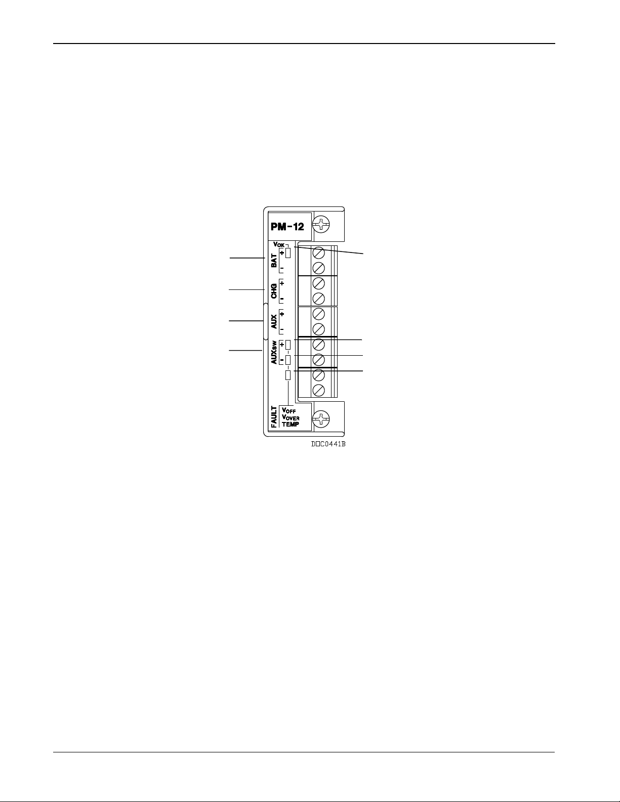
DL8000 Preset Instruction Manual
VOK LED
V
LED
V
LED
TEMP LED
BAT+ / BAT–
CHG+ / CHG–
AUX+ / AUX–
AUXSW+ / AUXSW–
3.1.1 12 Volt DC Power Input Module
The DL8000 accepts 12 Volts dc (nominal) input power from an
internally mounted AC/DC converter. The 12 volt DC output from the
AC/DC converter is connected to the BAT+ and BAT– terminals. The
base system (CPU, power input, and backplane) requires less than 70
mA. The Power Input module economizes power consumption using 3.3
Volts dc switching power that provides power to the DL8000 modules
via the backplane. The DL8000 requires 11.25 to 14.25 Volts dc for
proper operation.
OFF
OVER
Figure 3-1. 12 Volt DC Power Input Module
The CHG+ and CHG– terminals comprise an Analog Input channel that
allows you to monitor a voltage, such as an external charging source
from a solar panel. These inputs are not normally used for the DL8000.
The AUX+ / AUX – terminals can be used to supply reverse-polarityprotected source voltage to external devices, such as a radio or solenoid.
The AUXSW+ / AUXSW– terminals can be used to provide switched
power for external devices. The AUXSW+ is turned off when a
software configurable voltage is detected at the BAT+ / BAT–
terminals.
3-2 Modules Revised April 2020
Table 3-1 details the specific connection information for the 12 Volt dc
(PM-12) Power Input module. Table 3-2 details the LED fault
indicators.
Page 41

DL8000 Preset Instruction Manual
Absolute Maximum: 11.25 to 16 Volts dc
Analog Input used to monitor an external
charging source.
Supplies reverse-polarity-protected
source voltage to external devices.
AUXSW+ and
AUXSW–
Supplies switched power for external
devices.
Signal
LED
VOK
Green LED on when voltage is in tolerance on BAT+ and BAT–.
V
OFF
Fault – Red LED on when the AUXSW+ output are disabled by the CPU control line.
V
OVER
Fault – Red LED on when AUXSW+ is disabled due to excess voltage on BAT+.
Fault – Red LED on when AUXSW+ output are disabled due to the excess temperature of the Power
Input module.
DOC0513A
Table 3-1. 12 Volt DC Power Input Terminal Block Connections
Terminal Blocks Definition Volts DC
Accepts 12 Volts dc nominal from an
BAT+ and BAT–
AC/DC converter or other 12 Volt dc
supply.
Recommended Operating Range: 11.25 to
14.25 Volts dc
CHG+ and CHG–
AUX+ and AUX–
Table 3-2. 12 Volt DC Power Input LED Fault Indicators
TEMP
3.2 Input/Output Modules
The I/O modules typically consist of a terminal block for field wiring
and connectors to the backplane. The DL8000 supports up to nine I/O
modules, and can accommodate a wide range of process inputs and
outputs. Each I/O module electrically connects to field wiring by a
removable terminal block. Refer to Figures 3-2 and 3-3.
0 to 18 Volts dc
BAT+ minus ∼0.7 Volts dc
0 to 14.25 Volts dc
Front View Side View
Revised April 2020 Modules 3-3
Figure 3-2. Typical I/O Module
Page 42
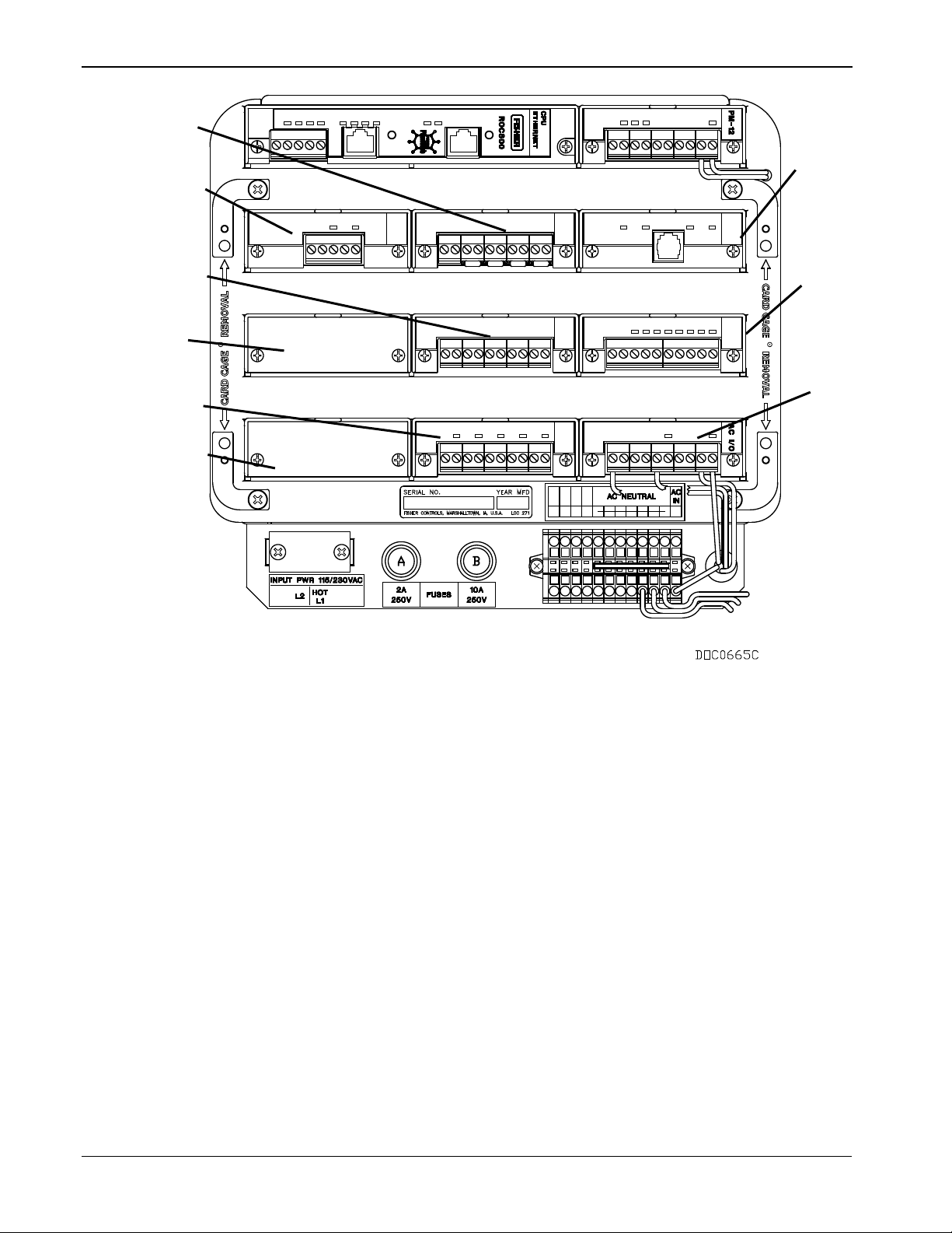
DL8000 Preset Instruction Manual
A
I/O Slot #5
I/O Slot #6
I/O Slot #8
F
I/O Slot #9
I/O Slot #1 or Comm 3
I/O Slot #4
I/O Slot #7 (AC I/O module)
G
A
B
H
D
C
E
F
I
I/O Slot #2 or Comm 3 or 4
B
I/O Slot #3 or Comm 3, 4, or 5
C
D
E
G
H
I
Figure 3-3. Optional I/O Module Locations
Available I/O modules for the DL8000 include:
Analog Input (AI) modules that provide the ability to monitor
various analog field values.
Discrete Input (DI) (for DC) and Pulse Input (PI) modules that
provide the ability to monitor various discrete and pulse input field
values.
3-4 Modules Revised April 2020
Page 43

DL8000 Preset Instruction Manual
Analog Output (AO), Discrete Output (DO), and Discrete Output
Relay (DOR) modules that provide the ability to control various
control devices.
The Alternating Current I/O Module (AC I/O) module provides the
ability to read the status of an AC input or control an AC output.
The Advance Pulse Module (APM) provides advanced functionality
typically found in liquids and gas measurement applications.
The RTD Input module provides the ability to monitor various
analog temperature field values.
The HART® interface module that enables the DL8000 to
communicate with devices using the Highway Addressable Remote
Transducer (HART) protocol as either Analog Inputs or Analog
Outputs.
Each module rests in a module slot at the front of the DL8000 housing.
I/O modules easily install into and remove from the module slots. You
can install and remove modules while the DL8000 is powered up (hotswappable). Modules may be installed directly into unused module slots
(hot-pluggable), and modules are self-identifying in the software. All
modules have removable terminal blocks to make servicing easy. I/O
modules can be added in any module slot.
Note: You can install comm modules only in slots 1, 2, or 3 of the
DL8000.
The I/O modules acquire power from the backplane. Each module has
an isolated DC/DC converter that provides logic, control, and field
power as required. The DL8000 has eliminated the need for fuses on the
I/O modules through the extensive use of current-limited short-circuit
protection and over voltage circuitry. Isolation is provided from other
modules and the backplane, power, and signal isolation. The I/O
modules are self-resetting after a fault clears.
3.2.1 General Installation
Each I/O module installs in the DL8000 in the same manner. You can
install any I/O module into any module socket, whether empty or in
place of another module.
Caution
Failure to exercise proper electrostatic discharge precautions (such as
wearing a grounded wrist strap) may reset the processor or damage
electronic components, resulting in interrupted operations.
When installing units located in a hazardous area (where explosive
gases may be present), make sure the area is in a non-hazardous state
before performing procedures. Performing these procedures in a
hazardous area could result in personal i n jury or property damage.
Revised April 2020 Modules 3-5
Page 44

DL8000 Preset Instruction Manual
Never connect the sheath surrounding shielded wiring to a signal
suitable earth ground.
You can insert or remove the I/O modules while power is connected to
the DL8000. If the DL8000 is powered, exercise caution while
performing the following steps to install a module.
Note: After you install a new I/O module or replace an existing I/O
3.2.2 Installing an I/O Module
To install an I/O module:
1. Remove the wire channel cover.
module, it may be necessary to reconfigure the DL8000. To
change configuration parameters, use ROCLINK 800 software
to make changes to the new module. Any added modules (new
I/O points) start up with default configurations. Refer to the
ROCLINK 800 Configuration Software User Manual (for
DL8000) (part D301259X012).
Note: Leaving the wire channel cover in place can prevent the
module from correctly connecting to the socket on the
backplane.
2. Perform one of the following:
If there was previously a module in the slot, unscrew the captive
screws and remove that module.
If the slot was previously unused, remove the module cover.
3. Insert the new I/O module into the module slot in the card cage.
Make sure the label on the front of the module is facing right side
up. Gently slide the module in place until it contacts the connectors
on the backplane.
Note: If the module stops and will not go any further, do not force
the module. Remove the module and see if the pins are bent.
If so, gently straighten the pin(s) and re-insert the module.
The back of the module must connect fully with the
connectors on the backplane.
4. Tighten the captive screws on the front of the module.
5. Wire the I/O module (refer to Section 3.2.4, Wiring I/O Modules).
6. Replace the wire channel cover.
Caution
ground terminal or to the common terminal of an I/O module. Doing so
makes the I/O module susceptible to static discharge, which can
permanently damage the module. Connect the shielded wiring only to a
7. Connect to ROCLINK 800 software and login. The I/O modules are
self-identifying after re-connecting to ROCLINK 800 software.
3-6 Modules Revised April 2020
Page 45

8. Configure the I/O point.
electronic components, resulting in interrupted operations.
3.2.3 Removing an I/O Module
To remove an I/O module:
1. Remove the wire channel cover.
2. Unscrew the two captive screws holding the module in place.
3. Gently pull the module’s lip out and remove the module from the
slot. You may need to gently wiggle the module.
4. Install a new module or install the module cover.
5. Screw the two captive screws to hold the module or cover in place.
6. Replace the wire channel cover.
3.2.4 Wiring I/O Modules
All modules have removable terminal blocks for convenient wiring and
servicing. The terminal blocks accommodate wire sizes between 12 and
22 AWG.
Caution
Failure to exercise proper electrostatic discharge precautions (such as
wearing a grounded wrist strap) may reset the processor or damage
DL8000 Preset Instruction Manual
To connect the wire to the removable block compression terminals:
1. Bare the end (¼ inch or 6.3mm maximum) of the wire.
2. Insert the bared end into the clamp beneath the termination screw.
3. Tighten the screw.
Expose a minimum of bare wire to prevent short circuits. Allow some
slack when making connections to prevent strain.
Note: All modules have removable terminal blocks for convenient
wiring and servicing. Twisted-pair cable is recommended for I/O
signal wiring. The removable terminal blocks accept wire sizes
between 12 and 22 AWG.
3.2.5 Analog Input (AI) Modules
The Analog Input (AI) modules (AI-12 and AI-16) have four scalable
channels, which typically measure either:
4 to 20 mA analog signal, with the use of a precision resistor
(supplied).
1 to 5 Volts dc signal.
Revised April 2020 Modules 3-7
Page 46
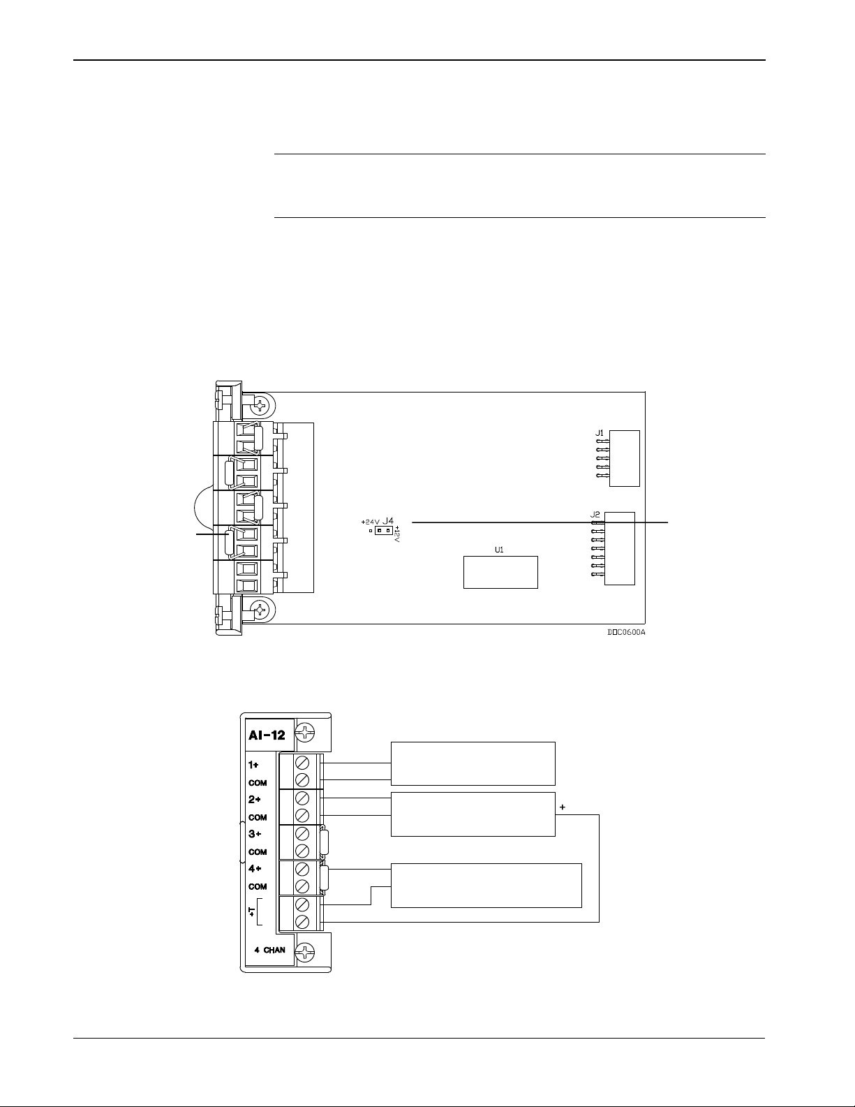
DL8000 Preset Instruction Manual
1-5 VOLT DEVICE
EXTERNALLY POWERED
+
-
1-5 VOLT DEVICE
EXTERNALLY POWERED
+
-
ROC809 POWERED
CURRENT LOOP DEVICE 4-20mA
-
+
OUT SIGNAL
COM IN
DOC0506A
Precision
Resistor
+T 12 / 24 V dc
Jumper
If required, you can calibrate the low end of the analog signal to zero
(refer to Chapter 7 in the ROCLINK 800 Configuration Software User
Manual) (for DL8000) (part D301259X012).
Note: The AI-16 module provides 16-bit resolution and uses a 24-bit
You can configure the AI (+T) as either 12 or 24 Volts dc using jumper
J4 on the AI-12 module (see Figure 3-4). The AI modules can provide
isolated +12 Volts dc or +24 Volts dc field transmitter power on a per
module basis. For example, one module can provide +12 Volts dc for
powering low-power analog transmitters, while another module in the
same DL8000 controller can provide +24 Volts dc for powering
conventional 4 to 20 mA transmitters. See Figure 3-5.
A/D converter. DIP switches on the AI-16 control the scaling
(see Figure 3-6).
Figure 3-4. AI-12 Jumper J4 (Shown Set to +12V)
3-8 Modules Revised April 2020
Figure 3-5. Analog Input Module Field Wiring
Page 47
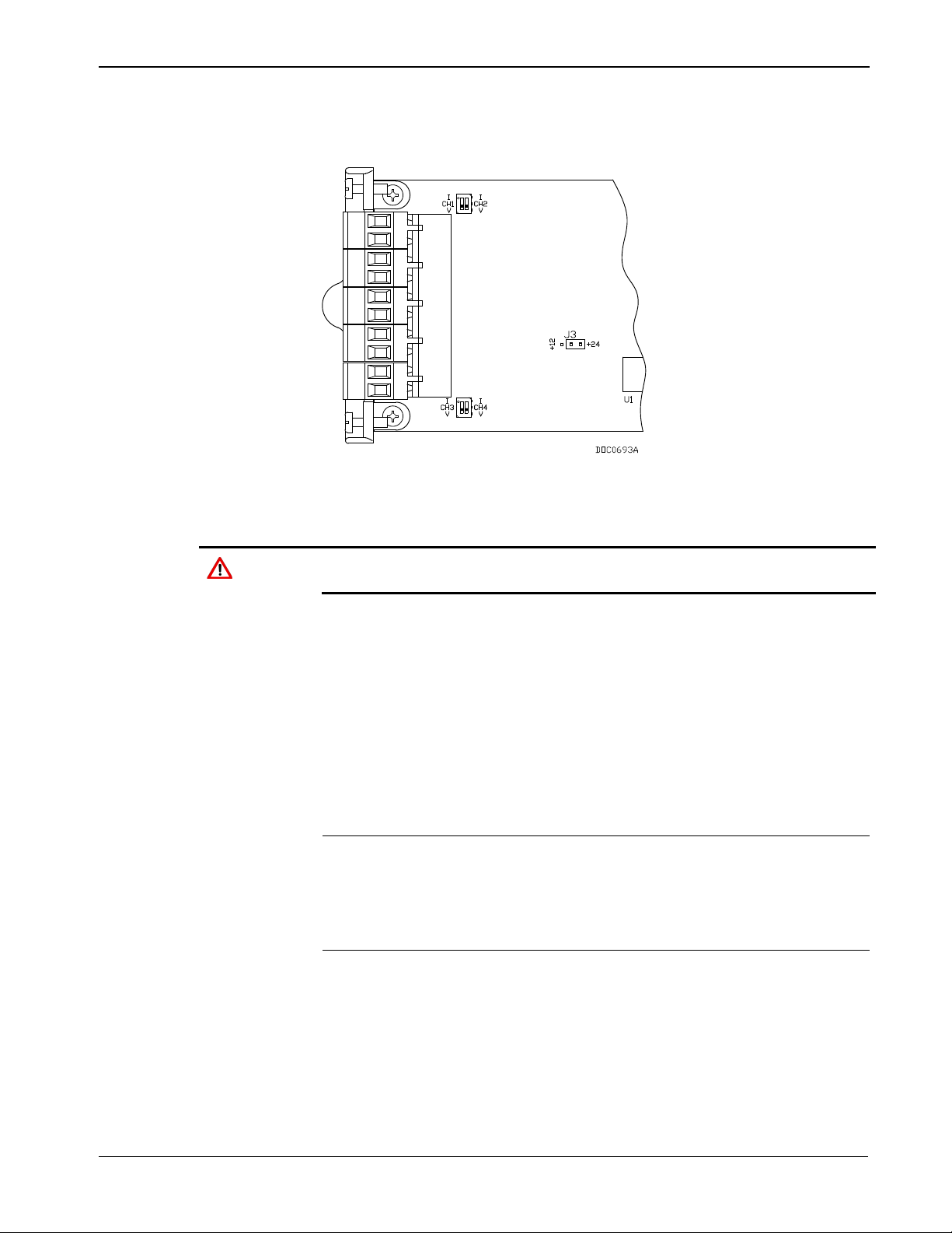
DL8000 Preset Instruction Manual
On the AI-16 module, you use jumper J3 to configure the AI (+T) as 12
or 24 Volts dc. Additionally, two DIP switches provide scaling control
(see Figure 3-6).
Figure 3-6. AI-16 DIP Switches
Caution
You can induce ground loops by tying commons from various modules
together.
3.2.6 Analog Output (AO) Modules
The 16-bit Analog Output (AO) module has four channels that provide a
current output for powering analog devices. Analog outputs are analog
signals the DL8000 controller generates to regulate equipment, such as
control valves or any device requiring analog control.
Each channel on this module provides a 4 to 20 mA current signal for
controlling analog current loop devices. The AO module isolation
includes the power supply connections.
Note: AO modules (Part Number W38199) with front labels that read
AO-16 are an earlier version that controls the low side current.
AO modules (Part Number W38269) with front labels that read
AO are the newer version (January 2005 and later) and control
the high side current.
You can configure the AO module as 12 or 24 Volts dc via jumper J4 on
the I/O module (see Figure 3-7). The AO module can provide isolated
+12 Volts dc or +24 Volts dc field transmitter power on a per module
basis. For example, one module can provide +12 Volts dc for powering
low power analog transmitters, while another module in the same
DL8000 controller can provide +24 Volts dc for powering conventional
4 to 20 mA transmitters. See Figure 3-7.
Revised April 2020 Modules 3-9
Page 48

DL8000 Preset Instruction Manual
+
-
I
+V
250
CONTROL
CURRENT LOOP
DOC0505A
CONTROL
CURRENT LOOP
CONTROL
CURRENT LOOP
CONTROL
CURRENT LOOP
+
-
ROC809 POWERED
CURRENT LOOP DEVICE 4-20mA
1-5 VOLT CONTROL DEVICE
+T 12 / 24 V dc
Jumper
Representative
Internal Circuit
Field Wiring
Figure 3-7. Analog Output Jumper J4 (Shown Set to +12V)
3-10 Modules Revised April 2020
Figure 3-8. Analog Output Module Field Wiring
You can induce ground loops by tying commons from various modules
Caution
together.
3.2.7 Discrete Input (DI) Modules
The eight-channel Discrete Input (DI) modules monitor the status of
relays, open collector/open drain type solid-state switches, and other
two-state devices. Discrete Inputs come from relays, switches, and
other devices, which generate an on/off, open/close, or high/low signal.
Page 49
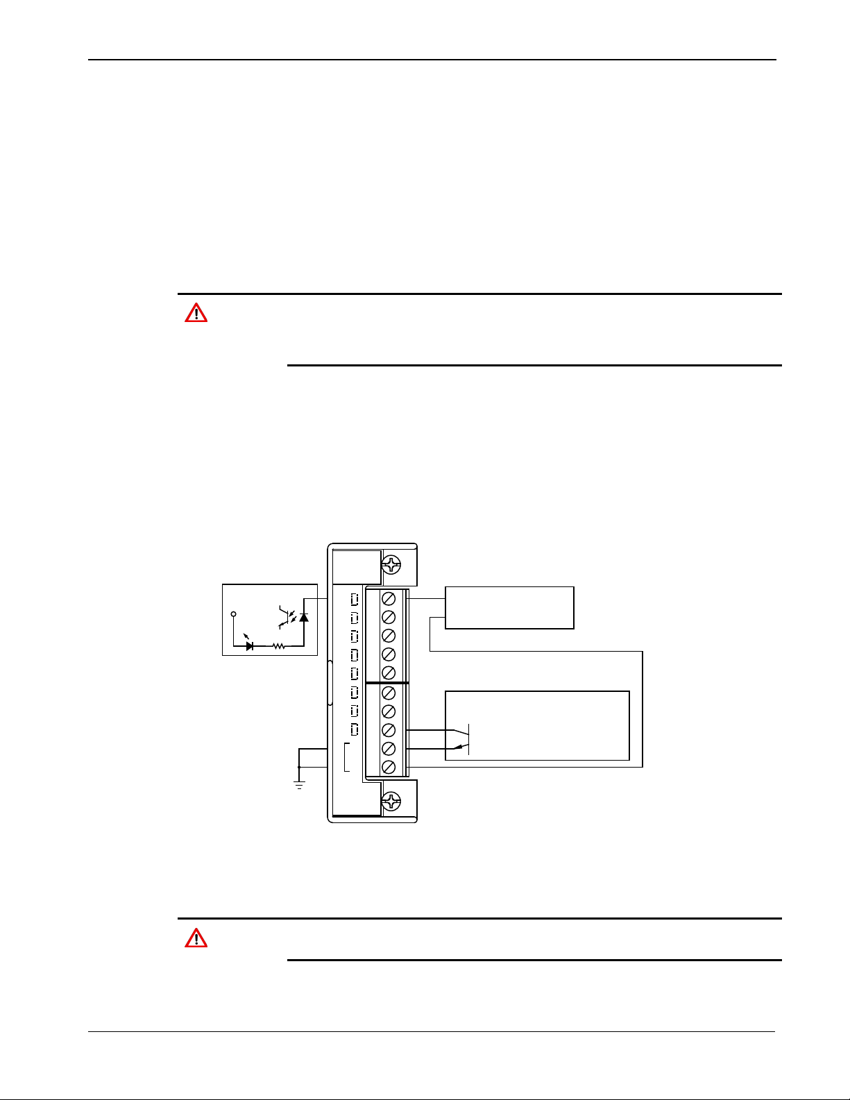
Caution
+
-
DRY CONTACT
ROC800 POWERED
+
-
+V
6.6KW
DOC0507A
C
O
M
6
8
7
4
5
3
2
1
DI
8 CHAN
OPEN DRAIN TYPE DEVICE
OR
OPEN COLLECTOR
EXTERNALLY POWERED
DL8000 Preset Instruction Manual
The DI module provides a source voltage for dry relay contacts or for an
open-collector solid-state switch.
The DI module’s LEDs light when each input is active.
You can configure each DI channel to function as a momentary or
latched DI (see the ROCLINK 800 Configuration Software User
Manual) (for DL8000) (part D301259X012). A latched DI remains in
the active state until reset. Other parameters can invert the field signal
and gather statistical information on the number of transitions and the
time accumulated in the on-state or off-state.
The Discrete Input module operates with non-powered discrete devices,
such as “dry” relay contacts or isolated soli d-state switches. Use of the
DI module with powered devices may cause improper ope ra tion or
damage.
The DI module senses the current flow, which signals the electronics in
the DL8000 that the relay contacts have closed. When the contacts open,
current flow interrupts, and the DI module signals the electronics in the
DL8000 that the relay contacts have opened. A DL8000 can read a DI a
maximum of 250 times per second.
The left side of Figure 3-9 displays the internal circuitry while the right
side of the diagram displays possible field wiring.
Caution
Figure 3-9. Discrete Input Module Field Wiring
You can induce ground loops by tying commons from various modules
together.
Revised April 2020 Modules 3-11
Page 50

DL8000 Preset Instruction Manual
damage.
3.2.8 Pulse Input (PI) Modules
The Pulse Input (PI) module provides two channels for measuring either
a low speed or high speed pulse signal. The PI module processes
signals from pulse-generating devices and provides a calculated rate or
an accumulated total over a configured period. Functions supported are
slow-counter input, slow rate input, fast counter input, and fast rate
input.
The PI is most commonly used to interface to relays or open
collector/open drain type solid-state devices. The Pulse Input can be
used to interface to either self-powered or DL8000-powered devices.
The high speed input supports signals up to 12 KHz while the low speed
input is used on signals less than 125 Hz.
You can configure the PI module as either 12 or 24 Volts dc using
jumper J4 on the module (see Figure 3-10). The PI modules can provide
isolated +12 Volts dc or +24 Volts dc field transmitter power on a per
module basis. For example, one module can provide +12 Volts dc
power, while another module in the same DL8000 controller can
provide +24 Volts dc power. See Figures 3-11 and 3-12.
Caution
The PI module provides LEDs that light when each input is active.
The Pulse Input module only operates with non-powered devices, such
as “dry” relay contacts or isolated solid-state switches. Use of the PI
module with powered devices may cause improper operation or
The PI modules draw power for the active circuitry from the backplane.
Input signals are optically isolated.
Note: Do not connect wiring to both the Low and High speed
selections for a given channel. Unpredictable operation of the PI
module will result.
3-12 Modules Revised April 2020
Page 51
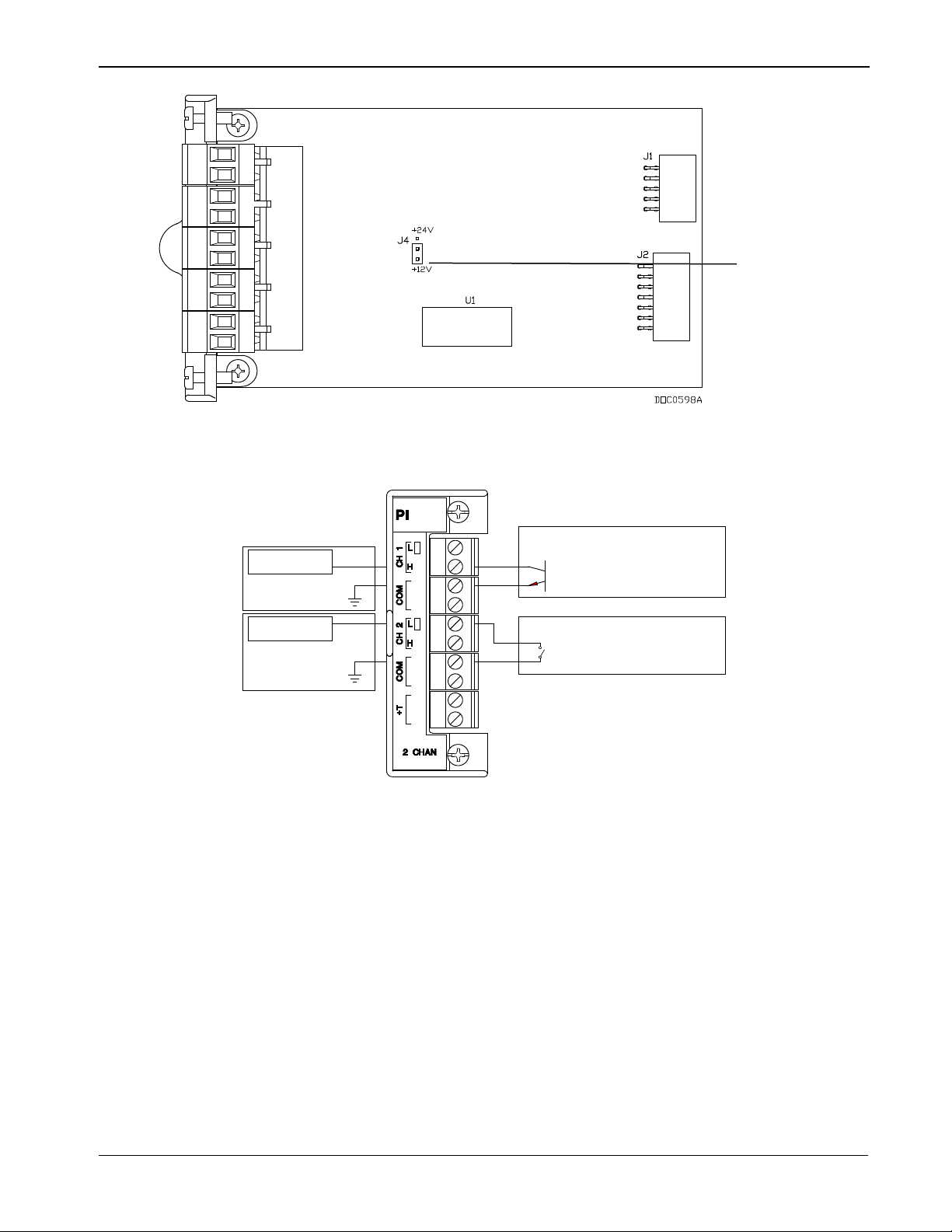
DL8000 Preset Instruction Manual
+
-
OPEN DRAIN TYPE
OR
OPEN COLLECTOR DEVICE
EXTERNALLY POWERED
+
-
CONTACT-CLOSURE DEVICE
EXTERNALLY POWERED
12KHz PI FILTER &
LEVEL DETECTION
12KHz PI FILTER &
LEVEL DETECTION
DOC0510A
+T 12 / 24 V dc
Jumper
Representative
Internal Circuit
Field Wiring
Figure 3-10. Pulse Input J4 Jumper (Set to +12 V)
Figure 3-11. Externally Powered Pulse Input Module Field Wiring
Revised April 2020 Modules 3-13
Page 52
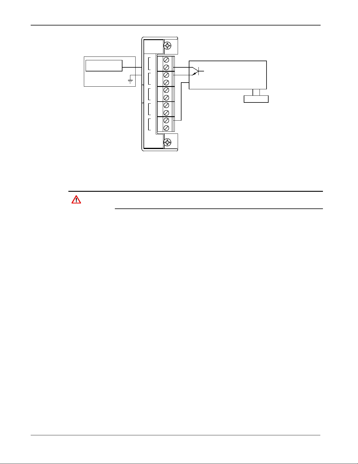
DL8000 Preset Instruction Manual
+
-
12KHz PI FILTER &
LEVEL DETECTION
+T
METER COIL
- +
DOC0511A
H
L
H
L
C
O
M
C
H
2
C
H
1
+
T
PI
2 CHAN
OPEN DRAIN TYPE DEVICE
OR
OPEN COLLECTOR
ROC800 POWERED
C
O
M
Representative
Internal Circuit
Field Wiring
Figure 3-12. DL8000 Powered Pulse Input Module Field Wiring
Caution
You can induce ground loops by tying commons from various modules
together.
3.2.9 Discrete Output (DO) Modules
The five-channel Discrete Output (DO) module provides two-state
outputs to energize solid-state relays and power small electrical loads.
These are solid-state relays. A Discrete Output may be set to send a
pulse to a specified device. Discrete Outputs are high/low outputs used
to turn equipment on/off. The DO module provides LEDs that light
when each output is active.
You can configure DO modules as latched, toggled, momentary, or
Timed Duration Outputs (TDO). You can also configure the DO to
either retain the last value on reset or use a user-specified fail-safe
value. Refer to the ROCLINK 800 Configuration Software User Manual
(for DL8000) (part D301259X012).
When a request is made to change the state of a DO, the request is
immediately sent to the DO module. There is no scan time associated
with a DO. Under normal operating conditions, the DO channel
registers the change within 2 milliseconds. If the DO is in momentary or
toggle mode, the minimum time on that can be entered is 4
milliseconds.
Figure 3-13 displays the field wiring connections to the output circuit of
the DO module.
3-14 Modules Revised April 2020
Page 53

DL8000 Preset Instruction Manual
damage.
+V
s
CONTROL
+
-
EXTERNALLY POWERED
DISCRETE DEVICE
+
-
-
C
OM
COM
COM
COM
COM
DO
2+
3+
4+
5+
1+
5 CHAN
DOC0508A
Representative
Internal Circuit
Field Wiring
Caution
The Discrete Output module only operates with non-powered discrete
devices, such as relay coils or solid-state switch inputs. Using the
module with powered devices may cause improper operation or
The DO modules draw power for the active circuitry from the
backplane. The DO module is current-limited for protection against
excessive current.
Note: When using a DO module to drive an inductive load (such as a
relay coil), place a suppression diode across the input terminals
to the load. This protects the module from the reverse ElectroMotive Force (EMF) spike generated when the inductive load is
switched off.
Revised April 2020 Modules 3-15
Figure 3-13. Discrete Output Module Field Wiring
Caution
3.2.10 Discrete Output Relay (DOR) Modules
You can induce ground loops by tying commons from various modules
together.
The five-channel DO Relay (DOR) module provides LEDs that light
when each output is active. DOR modules use dual-state latching relays
to provide a set of normally open, dry contacts capable of switching 2 A
at 32 Volts dc across the complete operating temperature. Using
ROCLINK 800, you can configure the module as latched, toggled,
momentary, or Timed Duration Outputs (TDO). You can configure the
DOR either to retain the last value on reset or to use a user-specified
fail-safe value.
Page 54

DL8000 Preset Instruction Manual
CONTROL
V
s
CONTROL
V
s
EXTERNALLY POWERED
DISCRETE DEVICE
+
-
-
+
SELF- POWERED
DISCRETE DEVICE
-
+
+
-
-
-
+
+
+
-
C
H
1
C
H
2
C
H
3
C
H
4
C
H
5
-YDO
RELA
5 CHAN
DOC0509A
RS
R
S
LATCHING RELAY
NOTE: S = SET
R = RESET
Figure 3-14 displays the field wiring connections to the output circuit of
the DO Relay module.
Note: The Discrete Output Relay module operates only with discrete
When a request is made to change the state of a DOR, the request is
immediately sent to the DOR module. There is no scan time associated
with a DOR. Under normal operating conditions, the DOR channel
registers the change within 12 milliseconds. If the DOR is in momentary
or toggle mode, DOR channels register the change within 48
milliseconds.
The DOR modules draw power for the active circuitry from the
backplane.
Note: On power up or reset, the DO Relay module’s LEDs enter
devices having their own power source.
indeterminate state for a few seconds as the module selfidentifies. The LEDs may flash, stay on, or stay off for a few
seconds.
3-16 Modules Revised April 2020
Figure 3-14. Discrete Output Relay Module Field Wiring
Caution
You can induce ground loops by tying commons from various modules
together.
Page 55

DL8000 Preset Instruction Manual
Connecting the RTD
Temperature can be input through the Resistance Temperature
Signal
Terminal
Designation
CH 1 (REF)
1
Constant Current +
CH 1 (+)
2
V+ RTD
CH 1 (–)
3
V– RTD
CH 1 (RET)
4
Constant Current –
Not Connected
5
N/A
CH 2 (REF)
6
Constant Current +
3.2.11 Resistance Tempera t ure Detector (RTD) Input Modules
The Resistance Temperature Detector (RTD) module monitors the
temperature signal from an RTD source. The module can accommodate
input from a two-, three-, or four-wire RTD source.
The active element of an RTD probe is a precision, temperaturedependent resistor, made from a platinum alloy. The resistor has a
predictable positive temperature coefficient, meaning its resistance
increases with temperature. The RTD input module works by supplying
a small consistent current to the RTD probe and measuring the voltage
drop across it. Based on the voltage curve of the RTD, the signal is
converted to temperature by the DL8000 firmware.
The RTD input module monitors the temperature signal from a
Resistance Temperature Detector (RTD) sensor or probe. A 2-channel
16-bit RTD module is available. The RTD module isolation includes the
power supply connections.
The RTD modules draw power for the active circuitry from lines on the
backplane.
Wiring
It may be more convenient to perform calibration before connecting the
field wiring. However, if the field wiring between the DL8000 and the
RTD probe is long enough to add a significant resistance, then perform
calibration in a manner that considers this.
Detector (RTD) probe and circuitry. An RTD temperature probe
mounts directly to the piping using a thermowell. Protect RTD wires
either by a metal sheath or by conduit connected to a liquid-tight
conduit fitting. The RTD wires connect to the four screw terminals
designated “RTD” on the RTD module.
The DL8000 controller provides terminations for a four-wire 100-ohm
platinum RTD with a DIN 43760 curve. The RTD has an alpha equal to
0.00385 or 0.00392 Ω/Ω/°C. A two-wire or three-wire RTD probe can
be used instead of a four-wire probe; however, they may produce
measurement errors due to signal loss on the wiring. See Figure 3-15.
Wiring between the RTD probe and the DL8000 must be shielded wire,
with the shield grounded only at one end to prevent ground loops.
Ground loops cause RTD input signal errors.
Table 3-3. RTD Signal Routing
Revised April 2020 Modules 3-17
Page 56

DL8000 Preset Instruction Manual
Signal
Terminal
Designation
CH 2 (+)
7
V+ RTD
CH 2 (–)
8
V– RTD
CH 2 (RET)
9
Constant Current –
Not Connected
10
N/A
You can induce ground loops by tying commons from various modules
Terminal
4-Wire RTD
3-Wire RTD
2-Wire RTD
REF
Red
Jumper to +
Jumper to +
+
Red
Red, Jumper to REF
Red, Jumper to REF
–
White
White
White, Jumper to RET
RET
White
White
Jumper to –
Switchable I/O and
The module has one bank of six DIP switches on its daughterboard
six channels. Placing a switch in the ON position sets the
Jumper
4-Wire RTD
3-Wire RTD
2-Wire RTD
Red
Red
Jumper
Red
Jumper
Caution
together.
Figure 3-15. RTD Sensor Wiring Terminal Connections
Table 3-4. RTD Wiring
Note: The wire colors for the RTD being used may differ.
3.2.12 Alternating Cur rent Input/Output (AC I/O) Module
Warning
LEDs
3-18 Modules Revised April 2020
EMC issues restrict the use of the AC I/O module only to devices using
a PM-12 power module. You CANNOT use the AC I/O module in a device
that uses a PM-24 power module.
(see Figure 3-16), which controls the input/output status of each of the
Page 57

DL8000 Preset Instruction Manual
corresponding channel to output mode. Placing a switch in the OFF
AC Discrete Outputs
In output mode, the module provides up to six channels for switching
EXTERNAL AC
PWR/PERMISSIVE
AC CONTROLLED
DEVICE
AC CONTROLLED
DEVICE
CONTROL
SOLID-STATE
RELAY
V
s
CONTROL
SOLID-STATE
RELAY
V
s
SOURCE
position sets the channel to input mode. Dual-color light-emitting
diodes (LEDs) indicate the current status for each channel. Red means
AC source is being output. Green means the module has detected AC
on an input channel.
Figure 3-16. AC I/O DIP Switches
discrete AC. Each channel uses a solid-state normally open relay rated
at 1.5 Amps. Any AC switched out is directly related to the AC
switched in. Using ROCLINK 800, you can configure the module as
latched, toggled, momentary, or Timed Duration Outputs (TDOs).
Other parameters report the approximate load, over-current
conditions, and AC input status. Discrete outputs can be configured to
either retain the last value on reset or a user-specified fail-safe value.
See Figure 3-17.
Figure 3-17. AC I/O Module (Output Field Wiring)
Revised April 2020 Modules 3-19
Page 58

DL8000 Preset Instruction Manual
AC Discrete Inputs
You can configure each channel as an AC input/detector. Each
WAVE
RECTIFIER
AC FIELD
DEVICE
WAVE
RECTIFIER
AC FIELD
DEVICE
Terminal
Label
Definition
2
N
AC Neutral
3
1
Channel 1
5
3
Channel 3
6
N
AC Neutral
8
5
Channel 5
Note: If the label on your AC I/O module does not indicate 120/240V,
channel can detect the presence of an AC signal between 90 and 265
Vrms at 47 to 63 Hz. In discrete input mode the module monitors the
status of various AC sources.
You can also software-configure each channel to function as a latched
DI, which remains in active state until reset. Other parameters can invert
the field signal and gather statistical information on the number of
transitions and the time accumulated in the on or off state. The fastest
time that each channel within the module can be read is 20 times per
second. See Figure 3-18.
your module is designed for use only with 120V. Additionally,
all AC wiring must be shielded.
Figure 3-18. AC I/O Module (Input Field Wiring)
Note: If the label on your AC I/O module does not indicate 120/240V,
your module is designed for use only with 120V. Additionally,
all AC wiring must be shielded.
Table 3-5. Field Wiring Terminals
1 AC In AC Input (Permissive Power)
4 2 Channel 2
3-20 Modules Revised April 2020
7 4 Channel 4
Page 59

DL8000 Preset Instruction Manual
Terminal
Label
Definition
9
6
Channel 6
10
N
AC Neutral
Term
Definition
AC Input
The AC power applied to this terminal is the source for
configured as AC outputs.
AC Neutral
This terminal is connected to the system AC neutral and is
used a reference for all AC power.
Channels 1
through 6
Depending upon the configuration of the DIP switch, each
channel can be configured as an input or an output.
Multiple AC I/O
If you need to install more than one AC I/O module in the DL8000,
The field terminal wiring has the following definitions:
any channel that is configured as an output. The input to
this terminal should be externally fused with a 10 to 15
amp fuse. The channel has a green LED associated with it
to indicate when power is applied. This terminal is typically
wired to the permissive/safety circuitry so that if this circuit
trips, all power is removed from the channels that are
Modules
wire the modules as shown in Figures 3-19 and 3-20.
Revised April 2020 Modules 3-21
Page 60
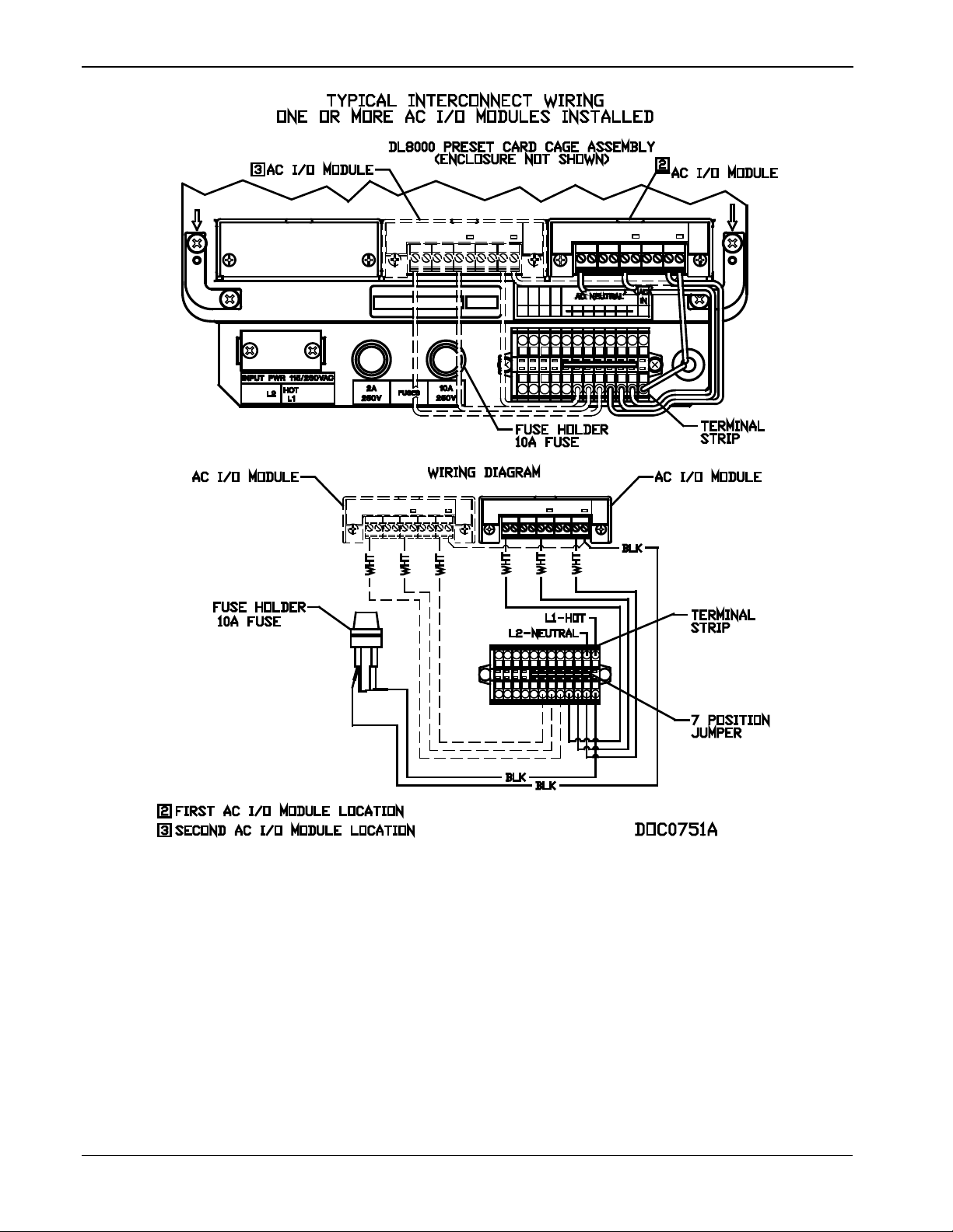
DL8000 Preset Instruction Manual
Figure 3-19. Wiring with Multiple AC I/O Modules
3-22 Modules Revised April 2020
Page 61
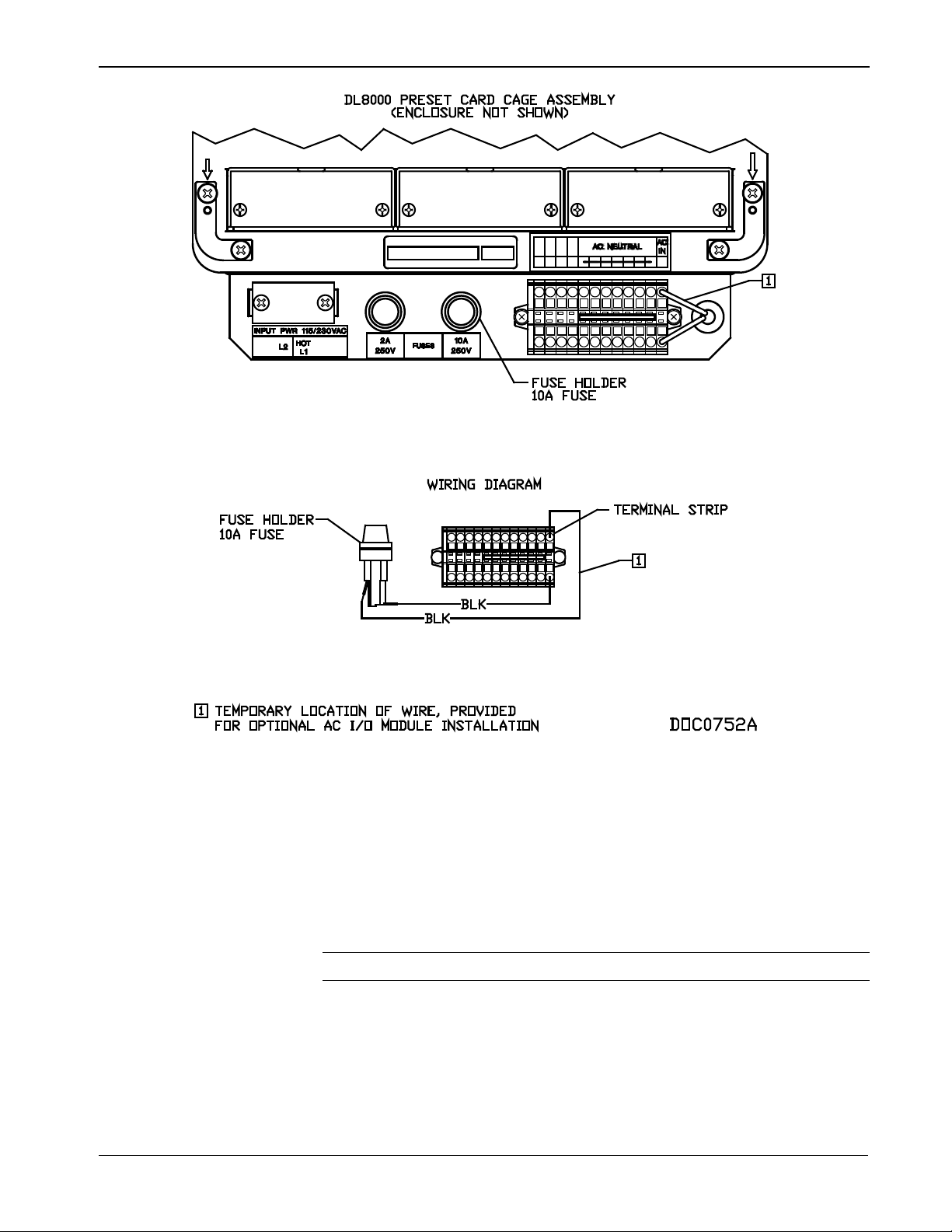
DL8000 Preset Instruction Manual
Figure 3-20. Fuse Wiring with Multiple AC I/O Modules
3.2.13 Advance Pulse Module (APM)
The APM provides advanced functionality commonly found in liquids
and gas measurement programs, including support for densitometer
inputs, detector inputs, pulse inputs, pulse frequencies, and pulse
outputs. Field wiring and DIP switch settings provide this flexibility.
See Figures 3-21 through 3-30.
Note: The DL8000 supports up to nine APMs.
For densitometer inputs, you can designate channel 3 as a pulse input
using a frequency input channel with hardware filtering for the Micro
Motion® 7835/7845 densitometer. You can designate channel 4 as a
pulse input or a solid state pulse output.
Revised April 2020 Modules 3-23
Page 62

DL8000 Preset Instruction Manual
-
+
OPEN COLLECTOR
EXTERNALLY POWERED DEVICE
OR
OPEN DRAIN TYPE
OPEN COLLECTOR
ROC800 POWERED DEVICE
OR
OPEN DRAIN TYPE
-
+
+T
METER
-
+
PI
COIL
PI
7835 / 7845
MICROMOTION
-
+
DENSITOMETER
PI
PI
DENSITOMETER
GENERIC
-
+
+T
PI
PI
+
DRY CONTACT
ROC800 POWERED
+
OPEN COLLECTOR
EXTERNALLY POWERED DEVICE
OR
OPEN DRAIN TYPE
-
DET SW 1 DET SW 2
DET SW 1
DET SW 2
Figure 3-21. Pulse Input Wiring on APM Figure 3-22. MicroMotion 7835/7845 Wiring on
APM
Figure 3-23. Generic Densitometer Wiring on APM Figure 3-24. Input Detector Wiring on APM
Figure 3-25. Series Detector Switch (Normally
Open) Wiring on APM
3-24 Modules Revised April 2020
Figure 3-26. Series Detector Switch (Normally
Closed) Wiring on APM
Page 63
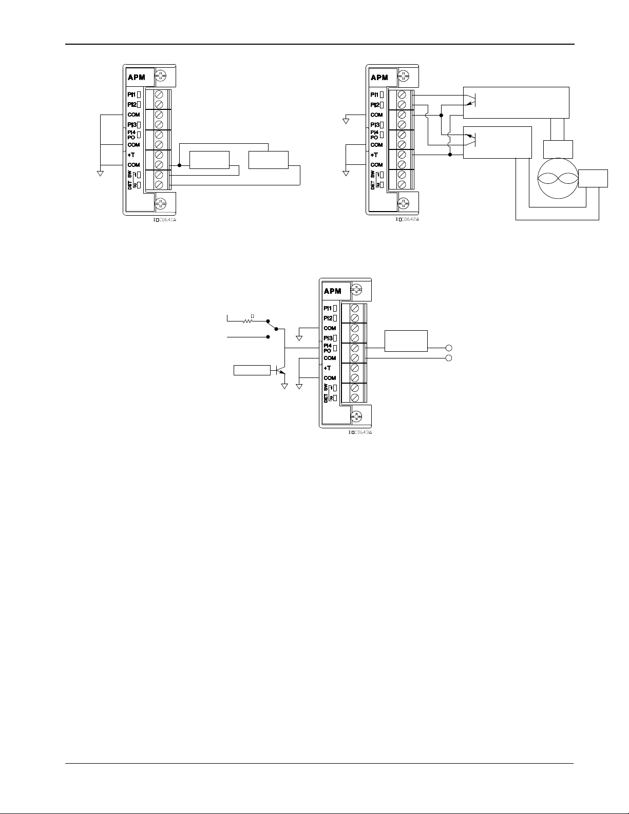
DL8000 Preset Instruction Manual
DET SW 1 DET SW 2
METER
-
+
METER
COIL 2
-
+
+
+T
METER
-
+
POWERED
EXTERNALLY
PREAMP
PREAMP
EXTERNALLY POWERED
+T
COIL 1
DEVICE
EXTERNAL
CONTROL
NO CONNECTION
+12
10K
DIP Switch
The APM card’s daughterboard contains several DIP switches which
Figure 3-27. Independent Detector Wiring on APM Figure 3-28. Two-Pulse Turbine Pulse Input Wiring
on APM
Figure 3-29. Pulse Output Wiring on APM
Settings
you use to control the module’s activities. See Figure 3-30 for the
switch locations and labels; see Table 3-6 for the settings.
Revised April 2020 Modules 3-25
Page 64

DL8000 Preset Instruction Manual
Switch
Channel
Side1
Function
Switch Position1
S2
S4
S1
S3
S5
Figure 3-30. DIP Switches on APM
Table 3-6. APM DIP Switch Settings
S1 3 N/A
2
1
Left
Current Modulated Densitometer Down
Left No Pullup Resistor Down
S2
Right
2
Right No Pullup Resistor Down
Left
3
Left No Pullup Resistor Down
S32
Right
4
Right No Pullup Resistor Down
Left
Detector 2
S4
Left No Pullup Resistor Down
Right
Detector 1
Right No Pullup Resistor Down
Left Pulse Output Up
S5
4
Left Pulse Input Down
N/A Right N/A N/A
1
Descriptors (up/down/right/left) assume that module terminal blocks face upward and dau ghterboard is visible
(see Figure 3-30)
2
If S1 is down, the 3-channel of this switch is non-functional; the 4-channel still functions normally.
Standard PI Up
10 kΩ Pullup to 12 V dc
10 kΩ Pullup to 12 V dc
10 kΩ Pullup to 12 V dc
10 kΩ Pullup to 12 V dc
10 kΩ Pullup to 12 V dc
10 kΩ Pullup to 12 V dc
Up
Up
Up
Up
Up
Up
3-26 Modules Revised April 2020
Page 65

3.2.14 Thermocouple (TC) I nput Module
If using the Type J above 750°C (1382°F), abrupt magnetic
De-calibration
De-calibration can occur in thermocouple wires. De-calibration is
DL8000 Preset Instruction Manual
Caution
The TC2 module is NOT supported in the Series 1 CPU.
The four-channel Thermocouple Input module monitors types B, C, E,
J, K, N, R, S, or T thermocouples, based on how you configure the
module with ROCLINK 800 Configuration software. The type of
thermocouple refers to the material used to make a bimetallic junction.
Dissimilar materials in the thermocouple junction generate different
millivolt levels as a function of the heat to which they are exposed.
The Thermocouple module measures the voltage of the thermocouple to
which it is connected. The TC voltage is measured and a Cold Junction
Compensation (CJC) correction factor is applied to compensate for
errors due to any voltage inducted at the wiring terminals by the
junction between the different metal of the TC wiring and the TC
module’s terminal blocks.
Note: The use of dissimilar metals is not supported. It does not provide
the correct results, as CJC is applied at the module level.
Thermocouples are self-powered and require no excitation current. The
TC module uses integrated short-circuit protected isolated power
supplies and completely isolates the field wiring side of the module
from the backplane.
Caution
transformation causes permanent de -calibration of the TC wires.
the process of unintentionally altering the makeup of the
thermocouple, usually caused by the diffusion of atmospheric
particles into the metal at the extremes of the operating temperature
range. Impurities and chemicals can cause de-calibration from the
insulation diffusing into the thermocouple wire. If operating at high
temperatures, check the specification of the probe insulation. It is
advised to use thermocouples with insulated junctions to protect
against oxidation and contamination.
Thermocouples use thin wire (typically 32 AWG) to minimize thermal
shunting and increase response times. Wire size used in the
thermocouple depends upon the application. Typically, when longer life
is required for the higher temperatures, select the larger size wires.
When sensitivity is the prime concern, use smaller size wiring. Thin
wire causes the thermocouple to have a high resistance that can cause
errors due to the input impedance of the measuring instrument. If
thermocouples with thin leads or long cables are required, keep the
thermocouple leads short and use a thermocouple extension wire to run
between the thermocouple and measuring instrument.
Revised April 2020 Modules 3-27
Page 66

DL8000 Preset Instruction Manual
Noise Susceptibility
Millivolt signals are very small and are very susceptible to noise.
Noise from stray electrical and magnetic fields can generate voltage
The thermocouple connects directly to the module’s removable terminal
block (see Figure 3-31). No special terminal or isothermal block is
required.
Figure 3-31. Thermocouple Input Module Wiring
Be sure to use the correct type of thermocouple wire to connect the
thermocouple to the DL8000. Minimize connections and make sure
connections are tight. If you use any dissimilar metals (such as copper
wire) to connect a thermocouple to the DL8000, you can create the
junction of dissimilar metals that can generate millivolt signals and
increase reading errors.
Ensure any plugs, sockets, or terminal blocks used to connect the
extension wire are made from the same metals as the thermocouples and
observe correct polarity.
The thermocouple probe must have sufficient length to minimize the
effect of conduction of heat from the hot end of the thermocouple.
Unless there is insufficient immersion, readings will be low. It is
suggested the thermocouple be immersed for a minimum distance
equivalent to four times the outside diameter of a protection tube or
well.
Use only ungrounded thermocouple constructions. Grounded
thermocouples are susceptible to the creation of ground loops. In turn,
ground loops can cause interaction between thermocouple channels on
the thermocouple module.
Note: Use thermocouples as individual sensing devices. All modules
are isolated on the field side. Be aware that you can induce
ground loops by tying module-to-module commons together.
3-28 Modules Revised April 2020
Page 67
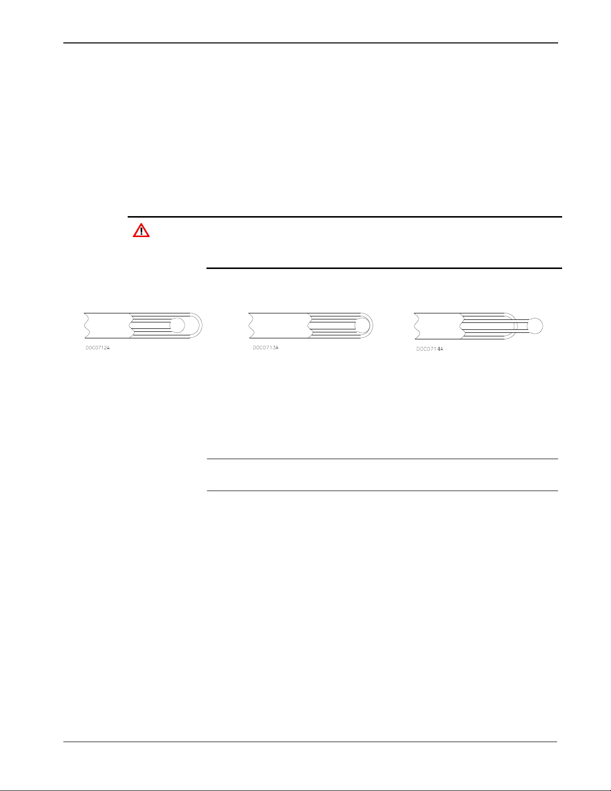
signals higher than the millivolt levels generated from a
Caution
thermocouple module to ground.
DL8000 Preset Instruction Manual
thermocouple. The TC modules can reject common mode noise
(signals that are the same on both wires), but rejection is not perfect,
so minimize noise where possible.
Take care to properly shield thermocouple wiring from noise by
separating the thermocouple wiring runs from signals that are switching
loads and AC signals. Route wires away from noisy areas and twist the
two insulated leads of the thermocouple cable together to help ensure
both wires pickup the same noise. When operating in an extremely
noisy environment, use a shielded extension cable.
Shielded wiring is highly recommended. Ground shields only on one
end, preferably at the end device unle ss you have an excellent ground
system installed at the ROC800-series controller. Do not tie the
Sheathed thermocouple probes are available with one of three junction
types: grounded, ungrounded, or exposed.
Figure 3-32. Ungrounded –
Sheathed
Figure 3-33. Grounded
Figure 3-34. Exposed,
Ungrounded – Unsheathed
In an ungrounded probe, the thermocouple junction is detached from
the probe wall. Response time slows down from the grounded style, but
the ungrounded probe offers electrical isolation of 1.5 M Ω at 500 Volts
dc in all diameters. The wiring may or may not be sheathed.
Note: Only ungrounded probes are supported. It is highly
recommended that you use sheathed probes.
Use an ungrounded junction for measurements in corrosive
environments where it is desirable to have the thermocouple
electronically isolated from and shielded by the sheath. The welded wire
thermocouple is physically insulated from the thermocouple sheath by
MgO powder (soft).
At the tip of a grounded junction probe, the thermocouple wires
physically attach to the inside of the probe wall. This results in good
heat transfer from the outside, through the probe wall to the
thermocouple junction. Grounded wiring is not supported.
The thermocouple in the exposed junction protrudes out of the tip of the
sheath and is exposed to the surrounding environment. This type offers
the best response time, but is limited in use to non-corrosive and nonpressurized applications. Exposed junction thermocouples are not
supported.
Revised April 2020 Modules 3-29
Page 68

DL8000 Preset Instruction Manual
Frequency
HART superimposes Frequency Shift Keying (FSK) signals on an
Point-to-Point Mode
In point-to-point mode, the analog signal is still representative of the
Multi-drop Mode
In multi-drop mode, you can connect up to five HART devices (in
Note: Avoid subjecting the thermocouple connections and
3.2.15 Highway Addressable Remote Transducer (HART®) Module
Notes:
The HART-2 module (labeled HART-2 with black faceplate)
The DL8000 supports up to 5 HART modules located in slots 1-5.
The HART-2 module allows a DL8000 to communicate with HART
devices using the HART protocol. The HART-2 module receives
signals from and transmits signals to HART devices. LEDs provide a
visual indication of the status of each HART channel. Refer to Figures
3-35 to 3-37.
Note: HART Pass-Through requires you to use the HART Pass-
measurement instrument to sudden changes in temperature.
replaces the HART module (with gray faceplate).
Through license key (FS8KY-6), which provides PlantWeb®
Smart Remote Automation functionality. This includes the
ability to pass HART data bi-directionally through the network
to AMS™ Device Manager software.
The module has four input/output channels. The HART-2 module uses
software-configurable switches, which allow you to set each channel as
input or output. When you set a channel as an input, you can configure
it for use in point-to-point or multi-drop mode (which typically connects
to some type of transmitter, such as a temperature reading). When you
configure a channel as an output, it reverts to point-to-point mode only.
The output supports a Digital Valve Controller (DVC). Each channel
has analog input capability intended for diagnostic and primary process
variable measurement.
Shift Keying
analog signal. This technique allows digital information to be passed
to and from the HART device on a 4 to 20 mA analog signal.
measured variable. This mode allows communications with one
HART device per channel.
parallel) to each channel. As with the point-to-point mode, digital
communications are superimposed on the analog signal used to power
the HART devices. Each HART device in multi-drop mode requires 4
mA and the current does not represent any measured variable value.
With all four channels in the multi-drop mode, the DL8000 can
support a maximum of twenty HART devices.
3-30 Modules Revised April 2020
Page 69

DL8000 Preset Instruction Manual
DL8000-powered
When using the DL8000 to power HART devices, connect terminal
Externally powered
When powering HART devices by an external device, connect the
A DL8000 equipped with a HART-2 module is considered to be a
HART Host (primary master) interface with a Class 1 Conformance
classification. The HART-2 module can also be configured with
ROCLINK 800 Configuration software for use as a secondary master in
redundant applications.
Most Universal and some Common Practice commands are supported.
For a list of the commands, refer to the ROC800-Series HART-2
Module technical specification sheet (ROC800:HART2). The supported
commands conform to HART Universal Command Specification
Revision 5.1 and Common Practice Command Specification Revision 7,
(HCF SPEC 127 and 151). Refer to www.hartcomm.org for more
information on the specifications.
The HART-2 module polls the channels simultaneously. If more than
one device is connected to a channel in a multi-drop configuration, the
module polls one device per channel at a time. The HART protocol
allows one second per poll for each device, so with five devices per
channel the maximum poll time for the channel would be five seconds.
HART Devices
HART Devices
Note: The DL8000 does not support HART devices configured in
Burst mode (in which the device sends information without a
prior request). If you have a HART device configured in burst
mode, use a hand-held field communicator to turn off burst
mode before you connect the device to the DL8000.
The HART-2 module provides “loop source” power (+T) and four
channels (1+ through 4+) for communications. The +T power is currentlimited.
+T in parallel to the positive (+) terminal on all of the HART devices,
regardless of the channel to which they are connected.
Wire channel 1+ to the negative (–) terminal of a single HART device,
or in parallel to the negative terminals of the devices. Likewise, wire
channel 2+ to the negative (–) terminal of a single HART device, or in
parallel to the negative terminals of a second group of HART devices
(see Figures 3-35 to 3-37).
positive (+) terminal from the power source in parallel to the positive
(+) terminal on all of the HART devices, regardless of the channel to
which they are connected.
Wire channel 1+ on the HART-2 module to the positive (+) terminal of
the HART device. Connect the power source negative (–) terminal to
the channel’s COM terminal and to the negative (–) terminal of a single
HART device, or in parallel to the negative terminals of the HART
devices.
Revised April 2020 Modules 3-31
Page 70

DL8000 Preset Instruction Manual
Figure 3-35. Input Point-to-Point Wiring on
HART-2 Module
Figure 3-37. Output Wiring on HART-2 Module
Figure 3-36. Input Multi-Drop Wiring on HART-
2 Module
3.3 Communication Modules and P orts
The built-in communications and the optional communication modules
provide communications between the DL8000 and a host system or
external devices.
The DL8000 allows up to six communication ports. Three
communication ports are built-in on the CPU and up to three additional
ports may be added with communication modules. Table 3-7 displays
the types of communications available for the DL8000; Table 3-8
defines the LED indicators.
3-32 Modules Revised April 2020
Page 71

DL8000 Preset Instruction Manual
EIA-232 (RS-232D) Local Operator Interface (LOI)
Local Port
Ethernet (use with DS800 Configuration Software)
Comm1
EIA-232 (RS-232C) Serial Communications
Comm2
Comm3 to Comm5
EIA-422/485 (RS-422/485) Serial Communications
Comm3 to Comm5
Modem Communications
Comm3 to Comm5
A
Built-in EIA-232 (RS-232) (Comm2)
Built-in Ethernet (Comm1)
C
LOI (Local Port) EIA-232 (RS-232D)
Optional Comm 3 – Slot #1
Optional Comm 3 or Comm 4 – Slot #2
Optional Comm 3 to Comm 5 – Slot #3
C
B
A
E
F
D
Table 3-7. Built-in Communications and Optional Communications Modules
Communications Built-in on CPU Optional Module
The communications modules consist of a communications module
(card), a communications port, wiring terminal block, LEDs, and
connectors to the backplane. The DL8000 can hold up to three
communication modules in the first three module slots. See Figure 3-38.
B
D
E
F
Revised April 2020 Modules 3-33
Figure 3-38. Communication Ports
Page 72

DL8000 Preset Instruction Manual
Clear To Send
Carrier Detect
Data Set Ready
Data Terminal Ready
Ready To Send
Receive Data
Transmit Data
Failure to exercise proper electrostatic discharge precautions, such as
electronic components, resulting in interrupted operations.
Table 3-8. Communication LED Indicator Definitions
Signals Action
CTS
CD Data
DSR
DTR
RTS
RX
TX
indicates the modem is ready to send.
(DCD) indicates a valid carrier signal tone detected.
for ring indicator communication signal.
to answer an incoming call. When off, a connection disconnects.
indicates ready to transmit.
(RD) signal is being received.
(TD) signal is being transmitted.
Each communications module has surge protection in accordance with
the CE certification EN 61000. Each communications module is
completely isolated from other modules and the backplane, including
power and signal isolation, with the exception of the EIA-232 (RS-232)
module. The field interface has been designed to protect the electronics
in the module. Filtering is provided on each module to reduce
communication errors.
3.3.1 Wiring Communications
Signal wiring connections to the communications are made through the
communications port removable terminal bock connectors and through
RJ-11 and RJ-45 connectors. All modules have removable terminal
blocks for convenient wiring and servicing. The terminal blocks
accommodate wire sizes between 12 and 22 AWG.
Caution
wearing a grounded wrist strap may reset the p rocessor or damage
To connect the wire to the removable block compression terminals:
1. Bare the end (¼ inch maximum) of the wire.
2. Insert the bared end into the clamp beneath the termination screw.
3. Tighten the screw.
Expose a minimum of bare wire to prevent short circuits. Allow some
slack when making connections to prevent strain.
Note: All modules have removable terminal blocks for convenient
wiring and servicing. Twisted-pair cable is recommended for I/O
signal wiring. The removable terminal blocks accept wire sizes
between 12 and 22 AWG.
3-34 Modules Revised April 2020
Page 73

DL8000 Preset Instruction Manual
RJ-45 Pins
on DL8000
Originated by the DL8000 Data Terminal Equipment (DTE) to
connection. DTE is running and ready to communicate.
Ground
(Common)
Reference ground between a DTE and a DCE and has a value 0
volts dc.
RX
Receive
5
Data received by the DTE.
TX
Transmit
6
Data sent by the DTE.
RTS
Request to Send
8
Originated by the DTE to initiate transmission by the DCE.
3.3.2 Local Operator Interface (LO I – Local Port)
The Local Operator Interface (LOI) port provides direct
communications between the DL8000 and the serial port of an operator
interface device, such as a personal computer (PC). The interface
allows you to access the DL8000 with a direct connection using
ROCLINK 800 software for configuration and transfer of stored data.
The LO I uses the Local Port in ROCLINK 800 software.
The LOI terminal (RJ-45) on the CPU (see Figure 3-38) provides wiring
access to a built-in EIA-232 (RS-232) serial interface, which is capable
of 57.6K baud operation. The RJ-45 connector pin uses the data
terminal equipment (DTE) in the IEEE standard.
The LOI port supports ROC Plus and Modbus protocol
communications. The LOI also supports the log-on security feature of
the DL8000 if you enable the Security on LOI feature in ROCLINK 800
software.
Table 3-9 shows the signal routing of the CPU connections. Figure 3-39
shows the RJ-45 pin out.
Signal LOI Function
DTR
GND
Data Terminal
Ready
Table 3-9. Built-in LOI EIA-232 Signal Routing
Description
3
4
instruct the Data Communication Equipment (DCE) to set up a
Figure 3-39. RJ-45 Pin Out
The LOI terminal requires a D-Sub 9 pin (F) to RJ-45 modular
converter installed between the DL8000 and a personal computer (PC).
See Table 3-10.
Revised April 2020 Modules 3-35
Page 74

DL8000 Preset Instruction Manual
EIA-232
DTE
4 – 1
1 – 2
6
DTR
3
5
GND
4
3
TX
5
2
RX 6 7 – 7
8
RTS
8
Adaptor Cable
Remote Automation Solutions offers an adaptor cable to resolve this
Table 3-10. RJ-45 to EIA-232 (RS-232) Null-modem Cable Signal Routing
(RS-232)
DL8000
RJ-45 Pins
on DL8000
cabling issue. Order CBL8A from your Remote Automation Solutions
salesperson.
3.3.3 Using the LOI
1. Plug the LOI cable into the LOI connector on the DL8000 CPU.
2. Connect the LOI cable to the D-Sub 9 pin (F) to RJ-45 modular
converter.
3. Plug the modular converter into the PC’s serial COM port.
4. Launch ROCLINK 800 software.
5. Click the Direct Connect icon.
6. Configure communications for the other built-in and modular
communications, I/O modules, AGA meter parameters, and other
configuration parameters.
3.3.4 Ethernet Communications
The Ethernet communications port in the DL8000 allows TCP/IP
protocol communications using the IEEE 802.3 10Base-T standard.
One application of this communications port is for downloading
programs from DS800 Development Suite Configuration Software.
The Ethernet communications port uses a 10BASE-T Ethernet interface
with an RJ-45 connector. Each Ethernet-equipped unit is called a station
and operates independently of all other stations on the network without
a central controller. All attached stations connect to a shared media
system. Signals are broadcast over the medium to every attached station.
To send an Ethernet packet, a station listens to the medium (Carrier
Sense) and when the medium is idle, the station transmits the data. Each
station has an equal chance to transmit (Multiple Access).
Access to the shared medium is determined by the Medium Access
Control (MAC) mechanism embedded in each station interface. The
3-36 Modules Revised April 2020
Page 75

DL8000 Preset Instruction Manual
Signal
Function
RX
Lit when currently receiving.
TX
Lit when currently transmitting.
COL
Lit when Ethernet Packet Collision detected.
LNK
Lit when Ethernet has linked.
MAC mechanism is based on Carrier Sense Multiple Access with
Collision Detection (CSMA/CD). If two stations begin to transmit a
packet at the same instant, the stations stop transmitting (Collision
Detection). Transmission is rescheduled at a random time interval to
avoid the collision.
Link Ethernet networks together to form extended networks using
bridges and routers. Table 3-11 maps the LEDs to functions.
Table 3-11. Ethernet Signal LEDs
Use a rugged industrial temperature HUB when connecting Ethernet
wiring in an environment that requires it.
The IEEE 802.3 10BASE-T standard requires that 10BASE-T
transceivers be able to transmit over a link using voice grade twistedpair telephone wiring that meets EIA/TIA Category four wire
specifications. Generally, links up to 100 meter (328 feet) long are
achievable for unshielded twisted-pair cable.
For each connector or patch panel in the link, subtract 12 meters (39.4
feet) from the 100-meter limit. This allows for links of up to 88 meters
(288 feet) using standard 24 AWG UTP (Unshielded Twisted-Pair) wire
and two patch panels within the link. Higher quality, low attenuation
cables may be required when using links greater than 88 meters.
The maximum insertion loss allowed for a 10BASE-T link is 11.5 dB at
all frequencies between 5.0 and 10.0 MHz. This includes the attenuation
of the cables, connectors, patch panels, and reflection losses due to
impedance mismatches to the link segment.
Intersymbol interference and reflections can cause jitter in the bit cell
timing, resulting in data errors. A 10BASE-T link must not generate
more than 5.0 nanoseconds of jitter. If your cable meets the impedance
requirements for a 10BASE-T link, jitter should not be a concern.
The maximum propagation delay of a 10BASE-T link segment must not
exceed 1000 nanoseconds.
Crosstalk is caused by signal coupling between the different cable pairs
contained within a multi-pair cable bundle. 10BASE-T transceivers are
designed so that you do not need to be concerned about cable crosstalk,
provided the cable meets all other requirements.
Revised April 2020 Modules 3-37
Noise can be caused by crosstalk of externally induced impulses.
Impulse noise may cause data errors if the impulses occur at very
specific times during data transmission. Generally, do not be concerned
Page 76

DL8000 Preset Instruction Manual
Signal
Signal
Pin 1 TD+
Pin 1 TD+
Pin 2 TD–
Pin 2 TD–
Pin 3 RD+
Pin 3 RD+
Pin 6 RD–
Pin 6 RD–
about noise. If you suspect noise related data errors, it may be necessary
to either reroute the cable or eliminate the source of the impulse noise.
Multi-pair, PVC 24 AWG telephone cables have an attenuation of
approximately 8 to 10 dB/100 m at 200°C (392°F). The attenuation of
PVC insulted cable varies significantly with temperature. At
temperatures greater than 400°C (752°F), use plenum rated cables to
ensure that cable attenuation remains within specification.
When connecting two twisted-pair MAUs (Medium Attachment Units)
or repeaters together over a segment, wire the transmit data pins of one
eight-pin connector to the receive data pins of the other connector, and
vice versa. There are two methods for accomplishing 10BASE-T
crossover wiring:
Special cable.
Wire the 10BASE-T crossover inside the hub.
For a single segment connecting only two devices, provide the signal
crossover by building a special crossover cable, wire the transmit data
pins of one eight-pin connector to the receive data pins of the other
connector, and vice versa. See Figure 3-40.
Figure 3-40. 10BASE-T Crossover Cable
3.3.5 EIA-232 (RS-232) Serial Communications
The built-in EIA-232 (RS-232), the LOI, and the communication
modules meet all EIA-232 (RS-232) specifications for single-ended,
asynchronous data transmission over distances of up to 15 meters (50
feet). EIA-232 (RS-232) communication provides transmit, receive,
and modem control signals. The LOI port also meets EIA-232D (RS232D) specifications.
The EIA-232 (RS-232) communications have the following
communication port designations in ROCLINK 800.
LOI – Local Port EIA-232 (RS-232D). Refer to Section 3.3.2, Local
Operator Interface.
Built-in – Comm2 EIA-232 (RS-232C).
3-38 Modules Revised April 2020
Module – Comm3 to Comm5 EIA-232 (RS-232C).
Page 77

DL8000 Preset Instruction Manual
Signal
LED Function
Terminal
RX
Lit when Comm2 is currently receiving.
1
TX
Lit when Comm2 is currently transmitting.
2
RTS
Lit when Comm2 ready to send is not active.
3
DTR
Lit when Comm2 data terminal ready is active.
4
GND
Common.
5
Signal
LED Function
Terminal
RX
Lit when module (Comm3, Comm4, or Comm5) is currently receiving.
1
TX
Lit when module (Comm3, Comm4, or Comm5) is currently transmitting.
2
RTS
Lit when module (Comm3, Comm4, or Comm5) is ready to send is not active.
3
DTR
Lit when module (Comm3, Comm4, or Comm5) data terminal ready is active.
4
GND
Common.
5
EIA-232 (RS-232) uses point-to-point asynchronous serial
communications and is commonly used to provide the physical interface
for connecting serial devices, such as gas chromatographs and radios to
the DL8000. The EIA-232 (RS-232) communication provides essential
hand-shaking lines required for radio communications, such as DTR and
RTS.
The EIA-232 (RS-232) communications includes LED indicators that
display the status of the Receive (RX), Transmit (TX), Data Terminal
Ready (DTR), and Ready To Send (RTS) control lines.
Table 3-12 defines the built-in EIA-232 (RS-232) terminals at the
Comm2 port and their function signals.
Table 3-12. Built-in EIA-232 (RS-232) Signal Routing – Comm2
The EIA-232 (RS-232) communications module provides for EIA-232
(RS-232C) signals on the Comm3, Comm4, or Comm5 port depending
on where the module is installed. See Table 3-13.
Table 3-13. EIA-232 (RS-232) Communication Module Signal Routing – Comm3, Comm4, and
Comm5
3.3.6 EIA-422/485 (RS-422/485) Serial Communications Module
EIA-422/485 (RS-422/485) communication modules meet all EIA422/485 (RS-422/485) specifications for differential, asynchronous
serial communication transmissions of data over distances of up to 1220
meters (4000 feet). EIA-485 (RS-485) communications are commonly
used to multi-drop units on a serial network over long distances using
inexpensive twisted-pair wiring.
EIA-422 (RS-422) drivers are designed for party-line applications
where one driver is connected to, and transmits on, a bus with up to ten
receivers. EIA-422 (RS-422) allows long distance point-to-point
communications and the drivers are designed for true multi-point
applications with up to 32 drivers and 32 receivers on a single bus.
Revised April 2020 Modules 3-39
Page 78
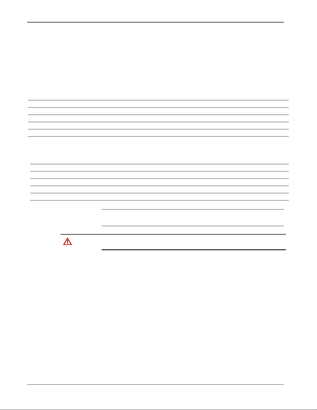
DL8000 Preset Instruction Manual
Signal
RS-422
Function
Terminal
A
RX +
Lit when module (Comm3, Comm4, or Comm5) is currently receiving.
1 B RX –
None.
2
Y
TX +
Lit when module (Comm3, Comm4, or Comm5) is currently transmitting.
3
Z
TX –
None.
4
COM
Common
Ground.
5
Signal
RS-485
Function
Terminal
A
RX / TX +
Lit when module (Comm3, Comm4, or Comm5) is currently receiving.
1
B
RX / TX –
Lit when module (Comm3, Comm4, or Comm5) is currently transmitting.
2
Y
No Connect
None.
3
Z
No Connect
None.
4
COM
Common
Ground.
5
The default values for the EIA-422/485 (RS-422/485) communications
are: 19200 Baud rate, 8 data bits, 1 stop bit, and no parity. The
maximum rate is 57.6K bps.
EIA-422/485 (RS-422/485) communication modules include LED
indicators that display the status of receive and transmit activity. See
Tables 3-14 and 3-15.
Table 3-14. EIA-422 (RS-422) Signal Routing – Comm3, Comm4, and Comm5
Table 3-15. EIA-485 (RS-485) Signal Routing – Comm3, Comm4, and Comm5
Note: The EIA-422/485 (RS-422/485) modules are isolated on the field
side.
Caution
You can induce ground loops by tying commons from various modules
together.
EIA-422/485 (RS-422/485) communications provides EIA-422/485
(RS-422/485) signals on the Comm3, Comm4, or Comm5 port
depending on where the module is installed. Wiring should be twistedpair cable, one pair for transmitting, and one pair for receiving. The
EIA-422 (RS-422) module uses four wires and the EIA-485 (RS-485)
uses two wires for connectivity.
3.3.7 EIA-422/485 (RS-422/485) Jumpers and Termination Resistors
Four jumpers—J3, J4, J5, and J6—are located on the EIA-422/485 (RS422/485) communications module (see Figure 3-41). These jumpers
determine in which mode the module runs (RS-422 or RS-485) and if
the module is terminated. See Tables 3-16 and 3-17.
Terminations are required on the two EIA-422/485 (RS-422/485)
communication modules located at the extremities of the circuit. That is
to say, the two outside modules require terminations in order to
complete the communications circuit.
3-40 Modules Revised April 2020
Page 79
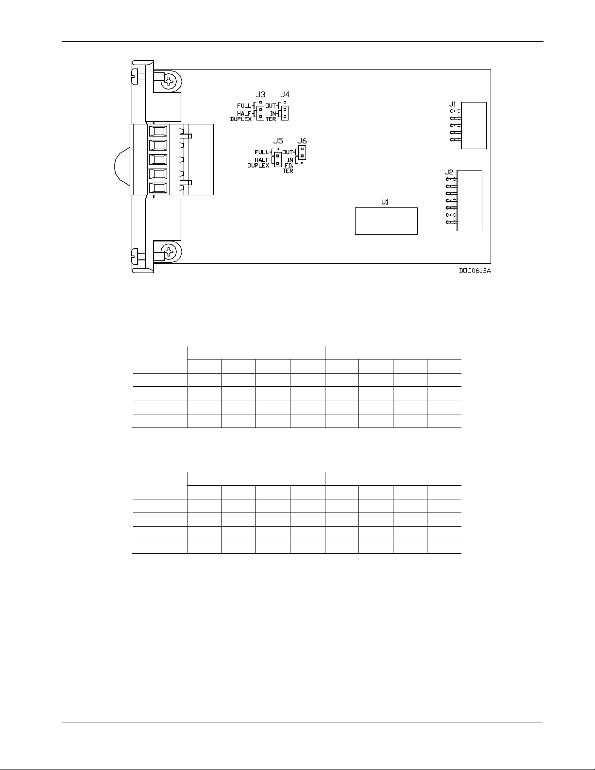
DL8000 Preset Instruction Manual
Terminated
Not Terminated
TER
Out
Half
Full
TER
Out
Half
Full
J3 x x
J4 x x
J5 x x
J6 x x
Terminated
Not Terminated
TER
Out
Half
Full
TER
Out
Half
Full
J3 x x
J4 x x
J5 x x
J6
x x
Figure 3-41. EIA-422/485 (RS-422/485) J4 Jumper
Table 3-16. EIA-422 (RS-422) Module
Jumper
Table 3-17. EIA-485 (RS-485) Module
Jumper
3.3.8 Dial-up Modem Communications Module
The dial-up modem module interfaces to a Public-Switched Telephone
Network (PSTN) line. The dial-up modem module provides for a
telephone interface on the host port that is capable of both answering
and originating telephone calls. The dial-up modem module also
provides electronics that conserve power when the phone line is not in
use. The dial-up modem module requires a telephone line connection.
Revised April 2020 Modules 3-41
Page 80

DL8000 Preset Instruction Manual
Signal
Pin
Tip 3 Ring
4
Signal
Function
Terminal
RX
Lit when module (Comm3, Comm4, or Comm5) is currently receiving.
1
TX
Lit when module (Comm3, Comm4, or Comm5) is currently transmitting (Tip).
3
RI
Lit when module (Comm3, Comm4, or Comm5) on ring (Ring).
7
CD
Lit when module (Comm3, Comm4, or Comm5) on carrier detect.
9
Note: When installing a dial-up modem module, you must remove
The dial-up modem provides communications with speeds up to 14.4K
bps with V.42 bis and V.42, MNP2-4 and MNP10 error correction.
The dial-up modem module is FCC Part 68 approved for use with
PSTNs. The FCC label on the module provides the FCC registration
number and the ringer equivalent. The dial-up modem module supports
data compression, error correction, and nonvolatile RAM for permanent
storage of the modem configuration.
The dial-up modem module interfaces to two-wire, full-duplex
telephone lines using asynchronous operation. The module interfaces to
a PSTN through an RJ-11 jack. The dial-up modem can be controlled
using industry-standard AT command software. A 40-character
command line is provided for the AT command set, which is compatible
with EIA document TR302.2/88-08006.
The dial-up modem automatically hangs up after a configured period of
communications inactivity. The dial-up modem provides automated
dial-up alarm reporting capabilities.
power from the DL8000.
Table 3-18. RJ-11 Field Connections
LED indicators on the module show the status of the Receive (RX),
Transmit (TX), Ring (RI), and Carrier Detect (CD) control lines. Table
4-19 displays connector signals and their functions.
Table 3-19. Modem Signal Routing – Comm3, Comm4, and Comm5
Notes:
If you are installing a modem module, it is recommended that you
install a surge protector between the RJ-11 jack and the outside line.
The dial-up modem is not hot-swappable or hot-pluggable. When
installing a dial-up modem module, you must remove power from
the DL8000.
3-42 Modules Revised April 2020
Page 81

3.4 Additional Technical Information
Name
Form Number
Part Number
ROC800-Series Analog Input Modules
ROC800:AI
D301238X012
ROC800-Series Alternating Current I/O Module
ROC800:ACIO
D301243X012
ROC800-Series Analog Output Module
ROC800:AO
D301260X012
ROC800-Series Advance Pulse Module
ROC800:APM
D301231X012
ROC800-Series Discrete Input Module
ROC800:DI
D301274X012
ROC800-Series Discrete Output Module
ROC800:DO
D301592X012
ROC800-Series Discrete Output Relay Module
ROC800:DOR
D301593X012
ROC800-Series HART®-2 Module
ROC800:HART2
D301705X012
ROC800-Series MVS I/O Module
ROC800:MVS
D301277X012
ROC800-Series Pulse Input Module
ROC800:PI
D301275X012
ROC800-Series Resistance Temperature Detector Module
ROC800:RTD
D301574X012
ROC800-Series Thermocouple Module
ROC800:TC2
D301689X012
ROC800-Series Power Input Modules
ROC800:PWR
D301192X012
ROC800-Series Communication Modules
ROC800:COM
D301171X012
Refer to the following technical documentation (available at
www.EmersonProcess.com/Remote) for additional and most-current
information on each of the modules.
Table 3-20. I/O Module Technical Specifications
DL8000 Preset Instruction Manual
Revised April 2020 Modules 3-43
Page 82

DL8000 Preset Instruction Manual
[This page is intentionally left blank.]
3-44 Modules Revised April 2020
Page 83

Appendix A – Glossary
A/D
ABS
Acrylonitrile Butadiene Styrene.
ADC
Analog to Digital Converter. Used to convert analog inputs (AI) to a format the flow
computer can use.
Additive
A liquid that is injected into a primary liquid component in relatively small quantities,
(ultrasonic) gas flow calculation standards. See http://www.aga.org.
AWG
AI
Analog Input.
AO
pressure of the gas.
AP
API
American Petroleum Institute. See http://www.api.org.
Area
ASCII
American (National) Standard Code for Information Interchange.
Attribute
A parameter that provides information about an aspect of a database point. For
Batch
A preset, quantity-based product delivery or blended component delivery of a single
Blend Stream
Note: This is a generalized glossary of terms. Not all the terms may
necessarily correspond to the particular device or software
described in this manual. For that reason, the term “ROC”
identifies all varieties of remote operations controllers.
A
Analog to Digital signal conversion.
usually less than four percent of the delivered volume total. Additives are injected into
the primary liquid component by an injector mechanism which places a known, fixed
volume of the additive into the primary liquid component stream for each injector pulse
received from the D L80 00 Pres et.
AGA
American Gas Association. A professional organization that oversees the AGA3
(orifice), AGA5 (heating value), AGA7 (turbine), AGA8 (compressibility), and AGA11
DL8000 Preset Instruction Manual
American Wire Gauge.
Analog Output.
Analog
Annubar
Absolute Pressure.
Arm
Analog data is represented by a continuous variable, such as an electrical current
signal.
A device that uses Pitot tubes to measure the gas flow rate within a pipeline. The gas
volume is calculated from the difference between the flowing pressure and the static
A user-defined grouping of database entities.
A movable pipe or hose assembly used at a tanker truck loading island (also: swing
arm, loading arm). The arm can be designed for either top loading or bottom loading to
the tanker compartments. A swing arm can be positioned to load at either side of the
loading island or the parked state.
example, the alarm attribute is an attribute that uniquely identifies the configured value
of an alarm.
B
recipe.
A product stream blen ded of both gasoline and ethanol.
Revised April 2020 Glossary A-1
Page 84

DL8000 Preset Instruction Manual
process.
BMV
BPS
Bits Per Second, associated with baud rate.
BTU
CID2
CMOS
Coil
Digital output, a bit to be cleared or set.
COL
COMM
before (upstream of) or after (downstream of) the component meter.
Configuration
Refers either to the process of setting up the software for a given system or the result
within the configuration screens.
CPU
Crosstalk
The amount of signal that crosses over between the receive and transmit pairs, and
CSMA/CD
CTS
Clear to Send modem communications signal.
DB
Blending
British Thermal Unit, a measure of heat energy.
Built-in I/O
The process of mixing two or more liquid components to form a composite delivered
stream. The DL8000 controls blending based on a predetermined recipe by either the
sequential (automatic or manual) or the inline (proportional or non-proportional)
method. The quantity of each component in a blend is typically greater than two to four
percent of the blended product. Injection of very small quantities of liquids, less than
four percent of the bl end ed pr oduct, is usually controlled by the additive injection
Base Multiplier Value, used in AGA7 (turbine) calculations.
I/O channels that are fabricated into the ROC and do not require a separate option.
Also called “on-board” I/O.
C
Class I, Division 2 hazardous area
CF Compare Flag; stores the Signal Value Discrete (SVD).
Complementary Metal Oxide Semiconductor, a type of microprocessor used in a ROC.
Ethernet Packet Collision.
COM Communications port on a personal computer (PC).
Communications port on a ROC used for host communications.
Comm Module
Component
Module that plugs into a ROC to provide a channel for communications via a specified
communications protocol, such as EIA-485 (RS-485) or HART.
Any liquid metered and controlled by the DL8000. Liquid hydrocarbons refined from
crude oil and LPGs (such as propane) are usually referred to as products. Components
are base products or tank products stored at a distribution terminal. The component is
measured before being blended with other components. Additives may be injected
of performing this process. The configuration activity includes editing the database,
building schematic displays and reports, and defining user calculations. Typically, the
software set up of a device that can often be defined and changed. Can also mean the
hardware assembly scheme.
Configuration
Tree
Central Processing Unit.
CRC Cyclical Redundancy Check error checking.
CSA Canadian Standards Association. See http://www.csa.ca.
In ROCLINK 800, the graphical display that appears when a configuration file opens
(also Directory Tree). It is a hierarchical branching (“tree-style”) method for navigating
signal attenuation, which is the amount of signal loss encountered on the Ethernet
segment.
Carrier Sense Multiple Access with Collision Detection.
D
D/A Digital to Analog signal conversion.
Database.
A-2 Glossary Revised April 2020
Page 85

DL8000 Preset Instruction Manual
setpoint and matches the desired result against a set of discrete inputs (DI).
DCE
DI
Discrete Input.
Discrete
DMM
Digital multimeter.
DO
Download
The process of sending data, a file, or a program from a PC to a ROC.
DP
DSR
Data Set Ready modem communications signal.
DTE
DTR
Data Terminal Ready modem communications signal.
conserves power for I/O channels, radios, and so on.
DVM
EDS
EFM
Electronic Flow Metering or Measurement.
connector.
(RS-422)
(RS-485)
devices to be connected together in a daisy-chained fashion.
EMF
EMI
Electro-Magnetic Interference.
ESD
dB
DCD
Data Communication Equipment.
Deadband
Device
Directory
Input or output that is non-continuous, typically representing two levels (such as on/off).
Discrete Output.
Differential Pressure.
Data Terminal Equipment.
Decibel. A unit for expressing the ratio of the magnitudes of two electric signals on a
logarithmic scale.
Data Carrier Detect modem communications signal. In addition, Discrete Control
Device – A discrete control device energizes a set of discrete outputs for a given
A value that is an inactive zone above the low lim its and below the high limits. The
purpose of the deadband is to prevent a value (such as an alarm) from being set and
cleared continuously when the input value is oscillating around the specified limit. This
also prevents the logs or data storage location from being over-filled with data.
In ROCLINK 800, the graphical display that allows navigation through the PC Comm
Ports and ROC Comm Ports set up screen.
Duty C ycle
DVS
Proportion of time during a cycle that a device is activated. A short duty cycle
Digital voltmeter.
Dual-Variable Sensor. A device that provides static and differential pressure inputs to a
ROC.
E
Electronic Static Discharge.
EEPROM
EIA-232
(RS-232)
EIA-422
EIA-485
EU Engineering Units. Units of measure, such as MCF/DAY.
Electrically Erasable Progr am mable Read-Only Memory, a form of permanent memory
on a ROC.
Serial Communications Protocol using three or more signal lines, intended for short
distances. Concerning RS232D and RS232C, the letters C or D refer to the physical
connector type. D specifies the RJ-11 connector where a C specifies a DB25 type
Serial Communications Protocol using four signal lines.
Serial Communications Protocol requiring only two signal lines. Can allow up to 32
Electro-Motive Force.
Electro-Static Discharge.
F
FCC Federal Communications Commission. See http://www.fcc.gov.
Revised April 2020 Glossary A-3
Page 86

DL8000 Preset Instruction Manual
storing values, and providing control signals.
module
applications firmware, and communications protocol.
permanent memory (requires no backup power). Also called Flash memory.
remote control. A FloBoss is a type of ROC.
FM
Force
Write an ON/OFF, True/False, or 1/0 value to a coil.
FPV
FSK
Frequency Shift Keypad.
Ft
GFA
GP
Holding
Hw
Indicated
Firmware
FlashPAC
Flash ROM
FloBoss
FST
Internal software that is factory-loaded into a form of ROM. In a ROC, the firmware
supplies the software used for gathering input data, converting raw input data values,
ROM and RAM module for a ROC300-Series unit that contains the operating system,
A type of read-only memory that can be electrically re-programmed. It is a form of
A microprocess-based device that provides flow calculations, remote monitoring, and
Factory Mutual.
Compressibility Factor.
Function Sequence Table, a type of user-written program in a high-level language
designed by Emerson Process Management’s Remote Automation Solutions Division.
Foot or feet.
G
Ground Fault Analysis.
GND Electrical ground, such as used by the ROC unit’s power supply.
Gauge Pressure.
Gross Quantity
The indicated quantity times the meter factor derived from a meter proving of the flow
meter at a specific flow rate. Calculation: gross quantity = indicated quantity times
meter factor.
H
HART® Highway Addressable Remote Transducer.
Register
Hz Hertz.
Analog output number value to be read.
Differential pressure.
I, J
IC
ID Identification.
IEC
IEEE
IMV Integral Multiplier Value, used in AGA3 (orifice) calculations.
Quantity
Input Digital input, a bit to be read.
Integrated Circuit. Also, Industry Canada (more recently known as Measurement
Canada), an organization that grants custody transfer approvals on certain ROC units.
Industrial Electrical Code or International Electrotechnical Commission. See
http://www.iec.ch.
Institute of Electrical and Electronic Engineers. A professional organization that, in
conjunction with the International Standards Organization (ISO), establishes and
maintains the Open System Interconnection (OSI) reference model and an international
standard for the organization of local area networks (LANs). Refer to
http://www.ieee.org.
The change in the flow meter reading that occurs during a product flow measurement
operation. (Not displayed by the DL8000 calculation: indicated quantity = end reading
minus start reading.)
A-4 Glossary Revised April 2020
Page 87

Input Register
Input numeric value to be read.
I/O
Input/Output.
I/O Module
Module that plugs into an I/O slot on a ROC to provide an I/O channel.
IRQ
Interrupt Request. Hardware address oriented.
ISO
IV
Integral Value.
KHz
LCD
For sequential blending
Note
LNK
DL8000 Preset Instruction Manual
IP-252
K
KB Kilobytes.
K-factor
L
LDP
LED Light-Emitting Diode.
Load
Loading Island
Loading Riser
Load Spot
Local Port
Logical Number
Institute of Petroleum standard 252. A British standard for pulse fidelity and security for
pulse output type flow meters. Program codes 233 and 234 define the operation of this
function.
Note: Equivalent standard is API Manual of Petroleum Measurement Standards /
Chapter 5 - Metering /
International Standards Organization. See http://www.iso.ch.
KiloHertz.
The pulses per unit quantity generated by a pulse output type flow meter (also system
factor). The nominal value is determined by flow meter design and factory water flow
calibration. The “average” K-factors for the flow meters are usually indicated on the
flow meter nameplates.
Liquid Crystal Display.
Local Display Panel, a display-only device that plugs into ROC300 (via a parallel
interface cable) used to access information stored in the ROC.
: In multi-component blending, a load is the completed
delivery of one component of a batch. The completion of loading all components in the
batch completes the batch delivery. If the recipe only loads one component, a load
corresponds to a batch delivery.
For inline blending: Each component of the blend is loaded simultaneously.
Depending on the blend ratio, the low-proportion components are loaded completely
during the time that the high proportion component(s) are being loaded. After loading of
the highest proportion component has been terminated, all component loads and the
batch delivery are complete.
Also loading rack; an installation of one or more loading arms or risers used to deliver
liquid components to a tanker vehicle located on one or both sides of the island,
depending on the design of the island.
The related instruments and devices, located in a meter stream, that provide the liquid
component loading capability to a mobile tanker vehicle.
: The flow meter piping can also be installed horizontally, if desired.)
Also bay or lane; one side of a loading island, a position where a tanker vehicle parks
for a loading operation. One load spot can have one or more loading arms.
Also LOI; the serial EIA-232 (RS-232) port on the ROC throu gh whic h loca l
communications are established, typically for configuration software running on a PC.
The point number the ROC and ROC Plus protocols use for I/O point types are based
on a physical input or output with a terminal location; the point numbers for all other
point types are “logical” and are simply numbered in sequence.
Ethernet has linked.
Revised April 2020 Glossary A-5
Page 88

DL8000 Preset Instruction Manual
configuration software running on a PC.
protection for ROCs.
LRC
m
mA
Milliamp(s); one thousandth of an ampere.
MAC Address
Media Access Control Address; a hardware address that uniquely identifies each node
of a network.
Manual mode
MCU
MPU
MMBTU
mV
NEC
NEMA
National Electrical Manuf ac turer ’s Assoc i ati on. See http://www.nema.org.
OH
Off-Hook modem communications signal.
LOI
LPM
Local Operator Interface (or Local Port). Refers to the serial EIA-232 (RS-232) port on
the ROC through which local comm unic ations ar e esta blish ed, t ypic a ll y for
Lightning Protection Module; a device that provides lightning and power surge
Longitudinal Redundancy Checking error checking.
M
Meter.
For a ROC, indicates that the I/O scanning has been disabled.
MAU Medium Attachment Unit.
Master Controller Unit.
Meter Factor
Meter Proving
Modbus A popular device communications protocol developed by Gould-Modicon.
mm Millimeter.
msec Millisecond, or 0.001 second.
MVS
mW Milliwatts, or 0.001 watt.
A number obtained by dividing the actua l volume of liquid passed through a flow meter
during a meter proving operation by the volume registered by the flow meter. The
meter factor is used in flow calculations to correct the indicated volume (end flow meter
registration minus start flow meter registration) to the observed gross volume (actual
flow meter throughput at operating conditions).
Meter factor = (Meter prover volume corrected to standard conditions) ÷ (Flow meter
indicated volume corrected to std conditions)
A procedure used to determine the meter factor for a flow meter. The K-factor (exact
number of pulses per a volume unit that a flow meter generates) is determined at the
factory. The K-factor is used to derive a mathematical factor, known as meter factor,
which is used to adjust results of the internal flow calculations the DL8000 performs.
Note: The flow meter is not re-calibrated; determining the meter factor allows the
operator to manually re-calibrate the DL8000 so that the flow meter’s
nonadjustable calibration characteristic [pulses per volume unit (K-factor)] are
incorporated into the flow calculations.
Micro-Processor Unit.
Million British Thermal Units.
Multi-Variable Sensor. A device that provides differential pressure, static pressure, and
temperature inputs to a ROC for orifice flow calculations.
Millivolts, or 0.001 volt.
N
National Electrical Code.
O
Off-line
A-6 Glossary Revised April 2020
Accomplished while the target device is not connected (by a communications link). For
example, “off-line configuration” refers to configuring an electronic file that is later
loaded into a ROC.
Page 89

DL8000 Preset Instruction Manual
Ohms
Units of electrical resistance.
load new values.
software, as well as host computers with ROC driver software.
PC
P/DP
PID
PLC
Point Number
The physical location of an I/O point (module slot and channel) as installed in the ROC.
Point Type
Defines the database point to be a specific type of point available to the system. The
point type determines the basic functions of a point.
Preset
mechanical or electrical preset counter.
PRI
Component
Primary Blend
Stream Meter
Protocol
A set of standards that enables communication or file transfers between two
On-line
Opcode
Operator
Interface
Orifice meter
Accomplished while connected (by a communications link) to the target device. For
example, “on-line configuration” refers to configuring a ROC800-Series unit while
connected to it, so that you can view the current parameter values and immediately
Type of message protocol the ROC uses to communicate with the configuration
Also LOI or Local Port; the serial EIA-232 (RS-232) port on the ROC through which
local communications are established, typically for configuration software running on a
PC.
A meter that records the flow rate of gas through a pipeline. The flow rate is calculated
from the pressure differential created by the fluid passing through an orifice of a
particular size and other parameters.
P, Q
Parameter
Permissive
Pf Flowing pres s ure.
PI Pulse Input.
PIT Periodic Timer Interrupt.
Point
A property of a point that typically can be configured or set. For example, the Point Tag
ID is a parameter of an Analog Input point. Parameters are normally edited by using
configuration software running on a PC.
Personal Computer.
A discrete signal from a device that is input to a discrete input in the DL8000. The
DL8000 uses this signal to allow a product delivery to be initiated or allow a product
delivery to continue. Permissive contacts are CLOSED in the normal or safe state and
OPEN in the abnormal or unsafe state.
Pressure/Differentia l Pres sur e.
Proportional, Integral, and Derivative control feedback action.
Programmable Logic Controller.
Software-oriented term for an I/O channel or some other function, such as a flow
calculation. Points are defined by a collection of parameters.
Number value previously determined for a register.
Also:
A generic term that describes the functional instrument group to whic h the DL8 000
belongs. The term originated from mechanical and electrical preset counters. The
DL8000 provides much more versatility and capability compared to a simple
Primary PID control loop.
Primary Blend
Stream
Revised April 2020 Glossary A-7
A blended product measured by a primary blend stream meter.
A meter measuring the gasoline-ethanol blend.
computers. Protocol parameters include baud rate, parity, data bits, stop bit, and the
type of duplex.
Page 90

DL8000 Preset Instruction Manual
PSTN
Public Switche d Telephone Network.
PT
PTT
Push-to-Talk signal.
Pulse
module
PV
Process Variable or Process Value.
Rack
are considered to be in “E” rack.
RAM
Random Access Memory. RAM is used to store history, data, most user programs, and
additional configuration data.
RBX
Report-by-exception. RBX always refers to Spontaneous RBX in which the ROC
contacts the host to report an alarm condition.
RR
RFI
Radio Frequency Interference.
RI
ROM
RTD
RTS
Ready to Send modem communications signal.
RTU
RTV
Room Temperature Vulcanizing, typically a sealant or caulk such as silicon rubber.
distances. Also referred to as the EIA-232 standard.
standard.
RX or RXD
Received Data communications signal.
Process Temperature.
Transient variation of a signal whose value is normally constant.
Pulse Interface
A module that provides line pressure, auxiliary pressure, and pulse counts to a ROC.
Quantity
The resulting amount of product measured after compensation for operational
temperature and pressure, indicated in one of the following corrected units: cubic
meters, liters, barrels, gallons.
R
A row of slots on a ROC into which I/O modules can be plugged. Racks are given a
letter to physically identify the location of an I/O channel (such as “A” for the first rack).
Built-in I/O channels are assigned a rack identifier of “A” while diagnostic I/O channels
Results Register; stores the Signal Value Analog (SVA).
Recipe
ROC
ROCLINK 800 Microsoft® Windows®-based software used to configure functionality in ROC units.
Rotary Meter
RTC Real-Time Clock.
A pre-entered delivery/blending/control description that allows the DL8000 to
automatically control the product quantity or total quantity based on percentages of
multiple components during a batch delivery operation. The DL8000 supports up to
thirty recipes.
Ring Indicator modem communications signal.
Remote Operations Controller microprocessor-based unit that provides remote
monitoring and control.
Read-only memory. Typically used to store firmware. Flash memory.
A positive displacement meter used to measure flow rate, also known as a Roots
meter.
Resistance Temperature Device.
Remote Terminal Unit.
RS-232
RS-422
RS-485
A-8 Glossary Revised April 2020
Serial Communications Protocol using three or more signal lines, intended for short
Serial Communications Protocol using four signal lines. Also referred to as the EIA-422
Serial Communications Protocol requiring only two signal lines. Can allow up to 32
devices to be connected together in a daisy-chained fashion. Also referred to as the
EIA-485 standard.
Page 91

S
SAMA
Side Stream
The controlled stream, often called the ethano l product. The side stream is metered
Side Stream
A mix component measured by both a side stream meter and a primary blend stream
Side Stream
Soft Points
A type of ROC point with generic parameters that can be configured to hold data as
SP
SPI
Slow Pulse Input.
SPK
Variables
T/C
TDI
Tf
Turbine meter
Script
DL8000 Preset Instruction Manual
Scientific Apparatus Maker’s Association.
An uncompiled text file (such as keystrokes for a macro) that a program interprets in
order to perform certain functions. Typically, the end user can easily create or edit
scripts to customize the software.
and can be controlled and measured.
Component
Meter
SRAM
SRBX
Standard
Quantity
SVA
SVD
System
meter. Ethanol is often referred as a side stream component.
A meter that measures the side component (ethanol).
desired by the user.
Setpoint, or Static Pressur e.
Speaker.
Static Random Access Memory. Stores data as long as power is applied; typically
backed up by a lithium battery or supercapacitor.
Spontaneous Report-By-Exception. SRBX always refers to Spontaneous RBX in which
the ROC contacts the host to report an alarm condition.
The gross quantity corrected to standard temperature and/or pressure. This is a
quantity measurement. Calculation: standard quantity = gross quantity times CTLM
(correction factor for the effect of temperature on the liquid in the meter) times CPLM
(correction factor for the effect of pressure on the liquid in the meter)
Signal Value Analog. Stored in the Results Register, it is the analog value that is
passed between functions in an FST.
Signal Value Discrete. Stored in the Compare Flag, it is the discrete value that is
passed down the sequence of functions in an FST.
Configured parameters that describe the ROC; set using ROCLINK software.
T
Thermocouple Input.
TCP/IP Transmission Control Protocol/Internet Protocol.
Time Duration Input.
TDO Time Duration Output.
Flowing temperature.
TLP Type (of point), Logical (or point) number, and Parameter number.
Transaction
TX or TXD Transmitted Data communications signal.
Group of one or more consecutive batch deliveries for accounting purposes. The
batches that comprise a transaction always use one recipe, one additive selection, and
one loading side. An example of a transaction is the delivery of multiple batches to
different compartments in a single tanker vehicle.
A device used to measure flow rate and other parameters.
U
Upload S end data, a file, or a program from the ROC to a PC or other host.
Revised April 2020 Glossary A-9
Page 92

DL8000 Preset Instruction Manual
V
V-Z
Volts.
Volume
Wild Stream
Wild Stream
Component
The actual space occupied by the product measured, indicated in one of the following
actual units: cubic meters, liters, barrels, gallons.
Wild stream is the uncontrolled stream, often referring to the gasoline product. This is
because the gasoline product cannot be exclusively metered, controlled, or measured.
A product component measured as part of (Primary Blend Stream Component – Side
Stream Component) a primary blend stream component by a primary blend stream
meter is called a wild stream component. Gasoline is referred as wild stream
component.
A-10 Glossary Revised April 2020
Page 93

DL8000 Preset Instruction Manual
Appendix B – Modbus Communications
This appendix describes how to configure a DL8000 for Modbus
communications.
Note: Refer to Chapter 3, Point Types, in the Preset Protocol
Specifications Manual (part D301254X012) for a discussion of
the point types and parameters associated with the DL8000
product.
B.1 Modbus Communicati ons
The DL8000 includes the ability to communicate using the Modbus
protocol. This enables you to integrate the DL8000 and Modbus devices
into the same host/slave system.
The DL8000 can act either as a slave or a host device.
The Modbus Master mode of operation (enabled on the ROC > Comm
Ports screen) allows the DL8000 to simulate a master device that can
poll other devices for data and then store that data for parameter
updates, for use in FST Registers, user programs, and DS800 programs.
The DL8000 can also send commands to set outputs and write data to a
slave device. For more information on Modbus master configuration
and functionality, refer to Section A.6, Modbus Master Table.
In slave mode, the data link between the host device and the DL8000
requires the use of one of the following communications ports:
Ethernet Port on the CPU.
EIA-232 (RS-232) Serial Communications Card.
EIA-485 (RS-485) Serial Communications Card.
Dial-up Modem Communications Card.
Note: Master mode supports the Comm 2 to Comm 5 communication
ports. The LOI and Comm 1 (Ethernet) ports do not support
Modbus master mode.
If a serial or modem communications port is configured with a port
owner of ROC Plus Protocol/Modbus Slave, the DL8000 automatically
determines if the incoming communication request is in ROC protocol
or Modbus protocol. The DL8000 responds using the same protocol as
the incoming request.
The Ethernet communications port automatically determines if the
incoming communication request is in ROC protocol, Modbus RTU
encapsulated in TCP/IP, or Modbus TCP/IP protocol. The DL8000
responds using the same protocol as the incoming request.
Revised April 2020 Modbus Communications B-1
Page 94
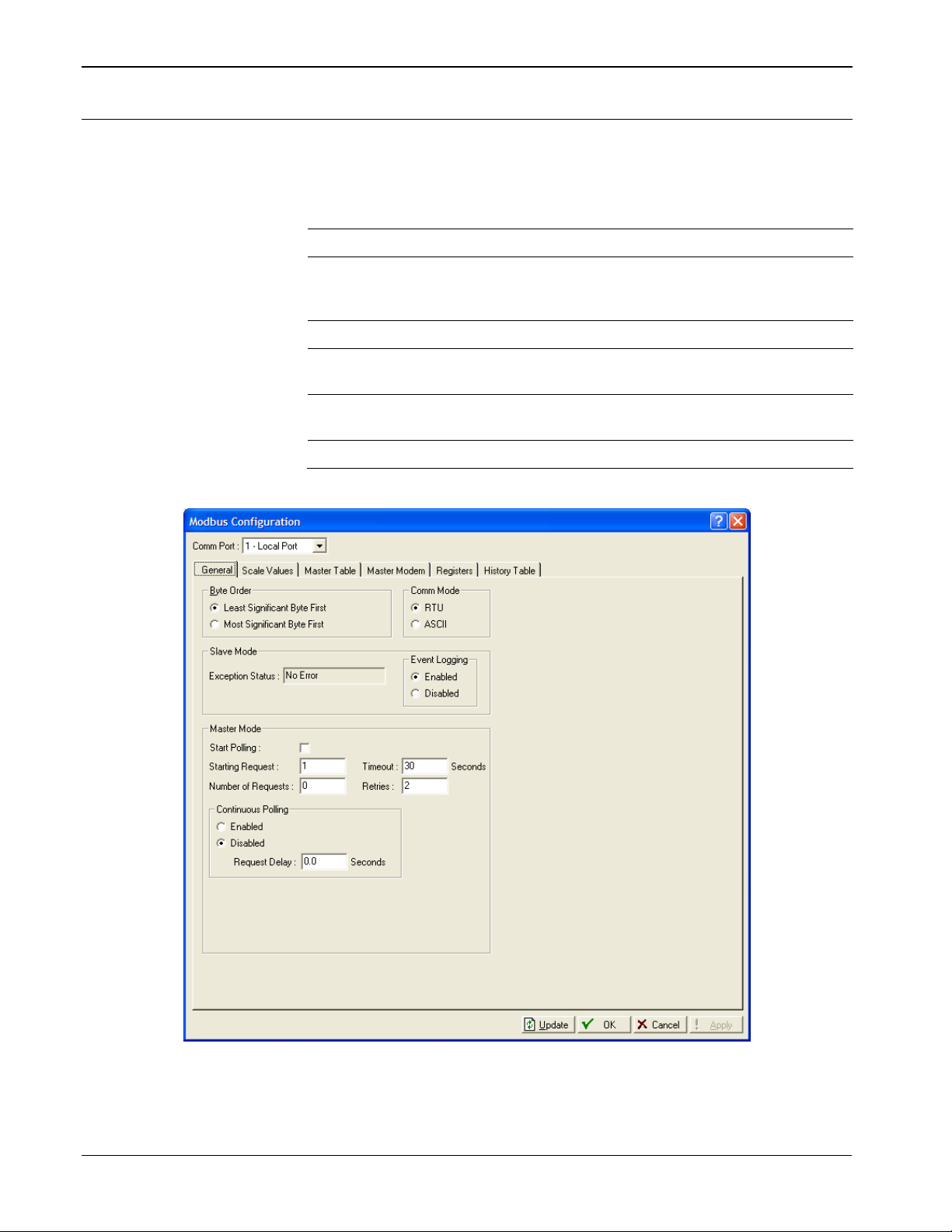
DL8000 Preset Instruction Manual
B.2 Modbus Configur a t ion
From the ROCLINK 800 menu bar, select Configure > MODBUS. The
Modbus Configuration screen displays, showing the General tab (see
Figure B-1). Use the individual tabs to:
Tab Use
General Defines basic communication parameters
Scale Values Defines up to eight low and high floating point scale
Master Table Simulates Modbus settings.
Master Modem Configures modems and maps RTU addresses to phone
Registers Maps Modbus registers to TLP values using either point
History Table Configures periodic and daily history values.
values and one low and high integer value for converting
floating point numbers to a scaled integer.
numbers.
indexing or parameter indexing.
Figure B-1. Modbus Configuration – General Tab
B-2 Modbus Communications Revised April 2020
Page 95

B.2.1 Modbus Configuration Genera l Ta b
Field
Description
Begin of Frame
Address
Function
Data
CRC Error Check
End
T1-T2-T3-T4
1 Byte
1 Byte
N x 1 Byte
2 Bytes
T1-T2-T3-T4
Begin of Frame
Address
Function
Data
LRC Error Check
End
:
2 Characters
2 Characters
N Characters
2 Characters
CRLF
Complete the following steps to configure the Modbus Configuration
screen’s General tab.
1. Review the values in the following fields:
Comm Port Indicates the port to configure. Click to display
additional available ports.
Byte Order Selects the order of data bytes in a transmission. You
can also reverse requests using this selection. Least
Significant Byte First is the default value.
Note: This selection affects only the Modbus
message’s data field. It has no effect on the
data for Function Codes 01, 02, and 05.
Comm Mode Indicates the communication mode. Select either
RTU or ASCII.
Note: In either mode, the transmitting device places
the Modbus message into a frame with a
known beginning and ending point. See
Tables A-1 and A-2.
DL8000 Preset Instruction Manual
RTU Remote Terminal Unit (RTU) mode allows
for greater character density and better
data throughput than ASCII for the same
baud rate. Each message is transmitted in
a continuous stream. Data is sent in 8-bit
binary characters. RTU mode uses Cyclic
Redundancy Check (CRC) error checking.
RTU is the default value.
ASCII American Standard Code for Information
Interchange (ASCII) mode represents each
8-bit byte of data as two ASCII characters
that are the hexadecimal representation of
the value. This allows the messages to be
read with the use of a dumb terminal, but
uses twice as many characters as the RTU
mode. Each character sent is composed of
a Start bit, 7 or 8 Data bits, and one or two
Stop bits with Even, Odd, or No parity.
ASCII mode uses Longitudinal Redundancy
Checking (LRC) error checking.
Table B-1. RTU Message Framing
Revised April 2020 Modbus Communications B-3
Table B-2. ASCII Message Framing
Page 96

DL8000 Preset Instruction Manual
Field
Description
Slave Mode This display-only field shows the error code for the
last received Modbus message. This field is
applicable only in slave mode. Valid valu es are:
0 No Error.
1 Illegal function.
2 Illegal data address.
3 Illegal data value.
Event Logging Ena bl es the DL8 000 to log all parameter changes
made through Modbus in the Event log. Valid values
are Enabled (log all events) or Disabled (allow
events to be changed but do not log those events).
The default is Enabled.
Start Polling
Starting Request Defines the starting number (entry) on the Modbus
Number of
Requests
Timeout Indicates, in seconds, the actual amount of time the
Retries Controls the number of times (in addition to the
Starts the Modbus Master polling sequence. Polling
begins with the Starting Request entry on the
Modbus Master Table and proceeds through the
entries in the table. The system resets this check box
when the polling sequence com pletes.
Note: You must have previously defined Modbus
Master as the port owner (select ROC >
Comm Ports > General tab).
Master Table from which polling begins.
Indicates the total number of requests in this polling
sequence.
DL8000 waits to receive a value message after it
sends a request to the device.
Note: Do not enter zero (0) in this field.
initial attempt) the Master DL8000 tries to establish
communications with the specif ied de vice bef or e
reporting a timeout error. Valid values are between 0
and 25. The default is 2.
Note: Use the Timeout field to adjust the amount of
time between retries.
B-4 Modbus Communications Revised April 2020
Continuous
Polling
Request Delay Sets, in seconds, a delay between polling request
Indicates whether the system executes the polling
sequence continually. Valid values are Enabled (the
polling sequence executes continually) or Disabled
(the polling sequence executes only on command).
The default is Disabled.
sequences.
Note: This field is valid only if you enable
Continuous Polling.
Page 97

DL8000 Preset Instruction Manual
Scale
Since each I/O point may have different scaling (or calibration), you
2. Click Apply to save any changes you have made to this screen.
3. Proceed to Section B.2.2 to define scale values.
B.2.2 Modbus Configuration Scale Values Tab
Select the Scale Values tab to enter up to eight low and high floating
point scale values and one low and high integer values for converting
floating point numbers to a scaled integer.
Figure B-2. Modbus Configuration – Scale Values Tab
use the Integer Scale’s Low Value and High Value fields to normalize
the raw values from the analog I/O points.
The Low Value and High Values fields are signed integers, and can
range from –32768 to 32767. You can also use these data fields to scale
the analog I/O to integer values with an implied decimal point.
For example, all analog I/O raw values can be transmitted with 0 to
1000 values (0 to 100.0, decimal point implied) by entering 0 in the
Low Value field and 1000 in the High Value field. This scaling is used
Revised April 2020 Modbus Communications B-5
Page 98

DL8000 Preset Instruction Manual
Float
In host systems that do not accept floating point numbers, you can
Equations
The system uses the following equations to convert floating point
Field
Description
only on analog I/O specified by the I/O: AI raw A/D input (Type 3,
Parameter 17) and AO raw D/A output (Type 4, Parameter 17).
specific up to eight sets of floating point ranges. This enables the host
to read and set floating point values (such as PID setpoints) as integer
values.
Note: The system converts the floating point values according to a
values to integers:
register or range of values you set in the Conversion field of the
Modbus Registers screen (Configure > MODBUS > Registers).
See Figure B-4.
Float Range = High Value Float Scale – Low Value Float Scale
Integer Range = High Value Integer Scale
Adjusted Reading = Float Reading
Integer = Integer Range x Adjusted Reading + Low Value Integer
Scale Float Range
– Low Value Float Scale
– Low Value Integer Scale
The system uses the following equations to convert integers to floating
point values:
Float Range = High Value Float Scale – Low Value Float Scale
Integer Range = High Value Integer Scale
Adjusted Integer = Integer Sent
Float Value = Adjusted Integer x Float Range + Low Value Float
Scale Integer Range
– Low Value Integer Scale
– Low Value Integer Scale
Complete the following steps to configure the Scale Value tab for the
Modbus Configuration screen.
1. Review the values in the following fields:
Integer Scale,
Low Value
Integer Scale,
High Value
Float Scale
1 through 8
Indicates the 0% value for scaling. Valid values are
–32768 to 32767.
Indicates the 100% value for scaling. Valid values are
–32768 to 32767.
Indicates up to eight sets (Low Value and High
Value) of floating point ranges the system uses when
the host is not able to process floating point numbers.
2. Click Apply to save any changes you have made to this screen.
3. Proceed to Section B.3 to configure Modbus history options.
B-6 Modbus Communications Revised April 2020
Page 99

B.3 Modbus History
Function
Code
32 - Event/Alarm
After Events and Alarms have been returned, an
DL8000 Preset Instruction Manual
Communications functionality in the DL8000 allows you to retrieve the
Periodic/Hourly and Daily history values and Event/Alarm records
through Modbus Protocol using Function Code 03. Each historical
record contains a time and date stamp on all of the history archives or
values for which you have configured the Register Number.
The system uses the Modbus Function Code 03 and the History Archive
Register to collect the archived data. Two separate Modbus registers
indicate the current Hourly and Daily history index. You configure these
on the Modbus Registers screen as the Hourly History Index Register
and the Daily History Index Register for the segment being referenced
(subtract 1 to get the last archived values). These indexes identify the
current history archive at which data is to be logged.
When the DL8000 receives a Function Code 03 request referencing the
Periodic History Index (commonly register 7161) or Daily History
Index (commonly register 7160), the host interprets the value returned
as an index into the specified history log. The host reads the indexes and
then compares the index to the last polled history index (which the host
maintains) to decide whether to request history.
03
05
If the host decides to request history, the reply message contains the
date and time stamp and historical values configured for the specified
register for that index.
For the DL8000, the response message contains two floating point
values for the time and date stamp of the history archive (time stamp =
HHMM and date stamp = MMDDYY) and floating point values for
each of the defined history points for that History Archive Register. The
history date stamp uses the current year and does not figure the number
of years since 1980. For example, if the current year is 2007, the year
(YY) for the date stamp would be 07. The DL8000 maps history
collection on the Modbus History Table.
Table B-3 summarizes the function calls and their associated register
and data fields.
Table B-3. Modbus History, Event, and Alarm Functionality
Register Field Data Field Description
32 - Event/Alarm
Register
Register
Ignored
Ignored
1
Response contains Event and Alarm records
number of bytes returned is 240 (12 records of 20 bytes
each). Events are returned before Alarms are returned. See
Table A-4 for the displayed format.
acknowledgment occurs so that the same Events and Alarms
are not returned on the next request.
2
. Maximum
Revised April 2020 Modbus Communications B-7
Page 100

DL8000 Preset Instruction Manual
Function
Code
Register Field Data Field Description
03
03
1
The Periodic Index, Daily Index, and Event/Alarm data fields address a history index number.
2
The Event and Alarm Log record consists of the bytes shown in Table A-4. Table A-5 provides a breakdown of the bit map in bytes 1-2.
703 - Daily
History
704 - Hourly
History
Daily Hist ory
Archive
Register Index
(0 to 34)
Hourly or
Periodic
History Archive
Register Index
(0 to 839)
Response contains two floating point values for the time and
date stamp of the history archive (time stamp = HHMMSS
and date stamp = MMDDYY) and floating point values for
each of the defined history points for that History Archive
Register.
Response contains two floating point values for the time and
date stamp of the history archive (time stamp = HHMMSS
and date stamp = MMDDYY) and floating point values for
each of the defined history points for that History Archive
Register.
B.3.1 Modbus Configuration Hi s t ory Table Tab
The Modbus History Table allows you to configure the Periodic and
Daily history values and Event/Alarm records for retrieval through
Modbus Protocol, using Function Code 03. You define three registers to
retrieve the current date in the DL8000, the current time in the DL8000,
and Event/Alarm records. You can also use the Modbus History Table
to define the Periodic and Daily registers for up to twenty groups of
history points.
Note: Before configuring the Modbus History, be sure to completely
configure the History Segment and History Point.
To access this screen:
1. Select Configure > MODBUS. The Modbus Configuration screen
displays.
2. Select the History Table tab. The Modbus History Table displays.
B-8 Modbus Communications Revised April 2020
 Loading...