

Page 1
Digital controller for medium-low temperature
refrigeration applications
XW60LH
1. GENERAL WARNING....................................................................................................................1
2. GENERAL DESCRIPTION ............................................................................................................1
3. CONTROLLING LOADS ................................................................................................................1
4. FRONT PANEL COMMANDS .......................................................................................................1
5. MAX & MIN TEMPERATURE MEMORIZATION ..........................................................................2
6. MAIN FUNCTIONS ........................................................................................................................2
7. PARAMETERS...............................................................................................................................2
8. DIGITAL INPUTS ...........................................................................................................................4
9. TTL SERIAL LINE – FOR MONITORING SYSTEMS ...................................................................4
10. X-REP OUTPUT – OPTIONAL ......................................................................................................4
11. INSTALLATION AND MOUNTING ................................................................................................4
12. ELECTRICAL CONNECTIONS .....................................................................................................4
13. HOW TO USE THE HOT KEY .......................................................................................................4
14. ALARM SIGNALS ..........................................................................................................................4
15. TECHNICAL DATA ........................................................................................................................5
16. CONNECTIONS .............................................................................................................................5
17. DEFAULT SETTING VALUES .......................................................................................................5
1. GENERAL WARNING
1.1 PLEASE READ BEFORE USING THIS MANUAL
• This manual is part of the product and should be kept near the instrument for easy and quick
reference.
• The instrument shall not be used for purposes different from those described hereunder. It cannot be
used as a safety device.
• Check the application limits before proceeding.
• Dixell Srl reserves the right to change the composition of its products, even without notice, ensuring
the same and unchanged functi onal ity.
1.2
SAFETY PRECAUTIONS
• Check the supply voltage is c orrect before connecting the ins trument.
• Do not expose to water or moisture: use the controller only within the operating limits avoiding sudden
temperature changes with high atmospheric humidity to prevent formation of condensation
• Warning: disconnect all electrical connections before any kind of maintenance.
• Fit the probe where it is not acc es sible by the End User. The instrument m ust not be opened.
• In case of failure or faulty operation send the instrument back to the distributor or to “Dixell S.r.l.” (see
address) with a detailed descri ption of the fault.
• Consider the maximum current w hi ch can be applied to each relay (see T ec hni cal Data).
• Ensure that the wires for probes, loads and the power supply are separated and far enough from each
other, without crossing or intertwining.
• In case of applications in industrial environments, the use of mains filters (our mod. FT1) in parallel
with inductive loads could be usef ul.
• Dixell Srl reserves the right to change the composition of its products, even without notice, ensuring
the same and unchanged functi onal ity.
2. GENERAL DESCRIPTION
Model XW60LH, format 38x 185mm, is microproces sor b ased co ntroller , suit able for appli cations on
medium or low temperature ventilated refrigerating units. It has 4 relay outputs to control compressor,
fan, defrost, which can be either electric al or r everse cycle (h ot gas) and a fourth configurable output .
They c ould be provid ed with a Real Time Cl ock which allows programmi ng of up to 6 daily defros t
cycles, divided into holidays and workdays. A “Day and Night” function with two different set points is
fitted for energy saving. They are al s o pr ov i d ed with up to four NTC or PTC probe inputs, the first one
for temperatur e control, the second one, t o be located ont o the evaporator , to control the d efrost
termination t emperature and to m anaged the fan. One of the digital in puts can oper ate as third
temperature pr ob e. T he fourth probe is used t o signal the co nd ens er t emp erat ur e alarm or to dis play
a temperature.
The HOT KEY output al lows to connect t he unit, by me ans of the external m odule XJ4 85-CX, t o a
network line ModBUS-RTU compatible such as the dIXEL monitoring units of X-WEB family. It
allows to program the controller by means the HOT KEY programming keyboard.
The instrumen t is fully configurabl e through special paramet ers that can be easily programmed
through the keyboard.
3. CONTROLLING LOADS
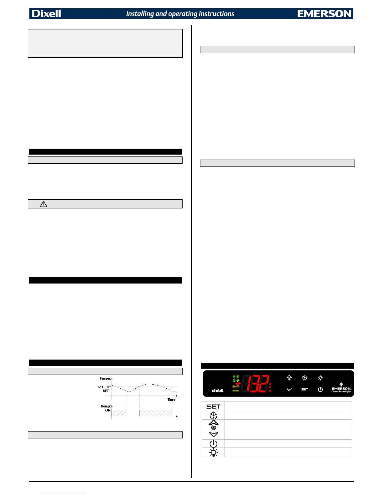
3.1 COMPRESSOR
The regulati on is perform ed accordin g
to the temperature measured by the
thermostat probe with a positive
differential from the set point: if the
temperature increases and reaches
set point plus differential the
compressor i s started an d then tur ned
off when the t emperature re aches the
set point value again.
In case of fault i n the thermostat probe t he start and stop of the com pressor are timed thr ough
parameters Con and CoF.
3.2 DEFROST
Two defrost mo des are av ail able thr ough t he tdF parameter: defr ost thr ough el ectric al hea ter (t dF =
EL) and hot gas defrost (tdF = in).
The defrost i nterval depends on the presence of the RTC (optional). If the RTC is pr esent is
controlled by means of parameter EdF:
- EdF=in: a defrost starts after elapsing the idF time (standard way for controller without RTC).
EdF=rtC: defrosts are sched uled by using a real time cl ock system, dependi ng on the h ours set in
the parameters Ld1..Ld6, during workdays, and in Sd1…Sd6 during holidays.
Other paramet ers are used to control defr ost cycles: i ts maximum le ngth (MdF) and two defrost
modes: timed or controlled by the evaporator’s probe (P2P).
At the end of defros t dri pping ti me is starte d, it s lengt h is set in th e Fdt parame ter. Wit h Fdt=0 the
dripping time is disabled.
3.3 CONTROL OF EVAPORATOR FANS
The fan control mode is selected by means of the FnC parameter:
- FnC=C_n: fans will switch ON and OFF with the compressor and not run during defrost;
- FnC=o_n: fans will run even if the compressor is off, and not run during defrost;
- FnC=C_Y: fans will switch ON and OFF with the compressor and run during defrost;
- FnC=o_Y: fans will run continuously also during defrost.
After defrost, t h er e is a tim ed fan delay allowi n g f or drip time, set by mea ns of the Fnd parameter.
An additional paramet er FSt provid es the set ting of t emperat ure, de tected by the eva porator probe,
above which th e fans are always OFF. Thi s is used to make sure cir culation of air only if his
temperature is lower than set in FSt.
3.3.1 Forced activation of evaporator fans
This function , managed by the FCt parameter, is designed to av oid short c ycles of evaporator fans,
which c ould ha ppen whe n the con troller i s switc hed on or af ter a defr ost (wh en the room ai r warms
the evaporator ). If t he temperature differenc e b etwe en the ev a por ator and th e room pr obes is higher
than the value set in the FCt parameter th e fans are switched on. Wit h FCt=0 this function i s
disabled.
3.3.2 Fans cyclic activation with compressor off.
When FnC=C-n or C-Y (fans working in paral lel with the compr es s or ) , by means of th e Fon and FoF
parameters t he f a ns c a n c ar r y out on and off cy c l es ev e n if the compressor is switc h ed off. When th e
compressor i s st op ped t he f ans g o on work in g for the Fon time. Wit h Fon=0 the fans r emai n always
off, when the compressor is off.
3.4 AUXILIARY OUTPUT CONFIGURATION
The functioni ng of the auxili ary relay can b e set by the oAx parameters acc ording to the ki nd of
application. In th e fol l owing paragraph the possible settings are explaided.
3.4.1 Auxiliary thermostat
A possible use i s the anti c ondensing heater, with t he possibil ity of switc hing it on and off also by
keyboard.
Parameters involved:
- ACH: kind of regulation for the auxiliary relay: Ht: heating; cL: cooling;
- SAA: set point for auxiliary relay;
- SHy: differe ntial for auxili ar y rel ay ;
- ArP: probe for auxiliary relay;
- Sdd: auxiliary output off during defrost.
The differential is given by the SHy parameter.
The auxiliar y r el ay c a n be switched on al s o by using the AUX button. In this cas e i t remains on till it’s
manually switched off.
NOTE: If oAx=AUS and ArP=nP (no pr obe for auxiliary outp ut) , the AUX relay can b e activated onl y
by pushing the AUX button of the keyboard.
3.4.2 On/off relay – oAx = onF
In this case the relay is activat ed when the controll er is turned on and de-activate d when the
controller is turned off.
3.4.3 Neutral zone regulation
With oAx=db the AUX relay can control a heater element to perform a neutral zone action.
- output oAx cut in = SET-HY;
- output oAx cut out = SET.
3.4.4 Second compr es sor
With oAx=CP2, the AUX rel ay operat es as secon d compress or: it is acti vated in par allel wit h the
relay of the fir st compressor, with a proper activation delay (set i n the AC1 parameter). Bot h the
compressors are switched off at the same time.
3.4.5 Alarm relay
With oAx=ALr the A UX relay oper ates as alarm r elay. It i s activ ated ev ery tim e an al arm hap pens.
Its status depends on the tbA parameter:
- tbA=Y: the relay is silenced by pr es s i n g any key;
- tbA=n: the alarm relay remains on until the alarm condition recovers.
3.4.6 Night blind management during energy saving cycles
With oAx=HES the AUX relay o perates to m anage the ni ght blind: the relay i s energised w hen the
energy saving cycle is activated by digital input, frontal button or RTC (optional).
4. FRONT PANEL COMMANDS
To display targe t s et point; in programm i ng mode it selects a parameter or
confirm an operation.
(DEF) To start a manual defrost.
(UP) To see the max stored temperature; in programming mode it browses the
parameter codes or increases the displayed value.
(DOWN) To see the min stored temperature; in programming mode it browses
the parameter codes or decreases the displayed value.
(OFF) To switch the instrument off, if onF=oFF.
(LiG) To switch the light, if oA3=Lig.
1592036000 XW60LH GB r1.0 18.03.2015 XW60LH 1/6
Page 2
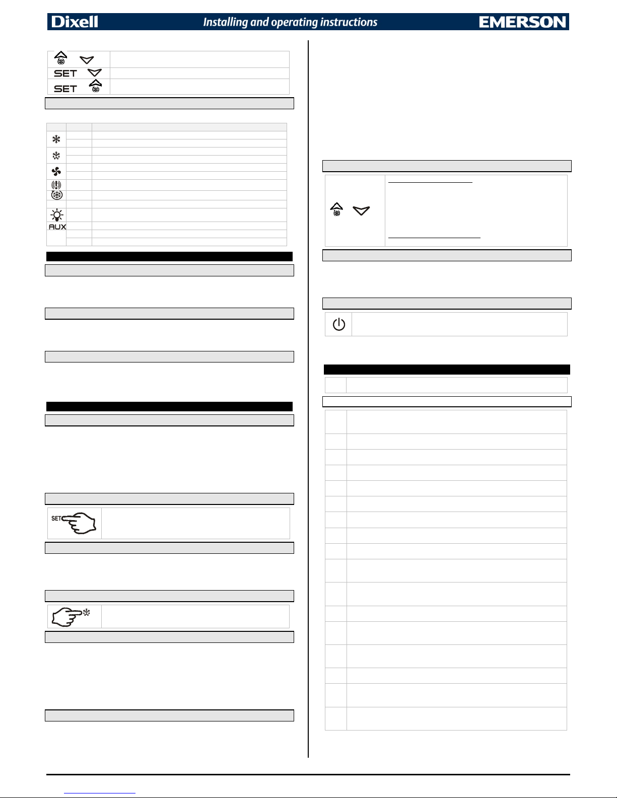
KEY COMBINATIONS:
+
To lock & unlock the keyboard.
+
To enter in programming mode.
+
To return to the room temperature display.
4.1 USE OF LEDS
Each LED function is described in the following table.
LED
MODE
FUNCTION
ON
Compressor enabled
Flashing
Anti-short cycl e delay enabled
ON
Defrost enabled
Flashing
Drip time in progress
ON
Fans enabled
Flashing
Fans delay after defrost in progr es s .
ON An alarm is occurring
ON
Continuous cy cle is running
ECO
ON
Energy saving enabled
ON Light on
ON
Auxiliary relay on
°C/°F
ON
Measurement unit
Flashing
Programming p hase
5. MAX & MIN TEMPERATURE MEMORIZATION
5.1 HOW TO SEE THE MIN TEMPERATURE
1. Press and release the DOWN key.
2. The “Lo” message will be displayed followed by the minimum temperature recorded.
3. By pressing the DOWN key again or by waiting 5 sec the normal dis pl ay wi ll be restored.
5.2 HOW TO SEE THE MAX TEMPERATURE
1. Press and release the UP key.
2. The “Hi” message will be displayed followed by the maximum recorded temperature.
3. By pressing the UP key again or by waiting 5 sec the normal display will be restored.
5.3 HOW TO RESET THE MAX AND MIN TEMPERATURE RECORDED
1. Keep SET key pressed m ore than 3 sec, while the max or min tem perature i s display ed. (rSt
message will be displayed).
2. To c onfirm the op eratio n the “r St” mess age st arts bli nking and th e normal temper ature w ill be
displayed.
6. MAIN FUNCTIONS
6.1 TO SET THE CURRENT TIME AND DAY (ONLY WITH RTC)
When the instrument is switched on, it’s necessary to program the time and day.
1. Enter the Pr1 programming menu, by pushing the SET+ DOWN keys for 3 sec.
2. The rtC parameter is displayed. Push the SET key to enter the real time clock menu.
3. The Hur (hour) parameter is displayed.
4. Push the SET and set c urrent hour by the UP and DOWN keys , then push SET to
confirm the value.
5. Repeat the same operations with Min (m inutes) and dAy (day) parame ter s .
To exit: Push both SET+UP keys or wait for 15 sec without pushing any keys.
6.2 HOW TO SEE THE SET POINT
1. Push and immediately release the SET key: th e di s play will show the
Set point value.
2. Push and immediately release the SET key or wait for 5 sec to
display the pro be val u e again.
6.3 HOW TO CHANGE THE SETPOINT
1. Pus h th e SET key more than 2 sec to change the Set point value;
2. The value of the set point will be displayed and the “°C” or “°F” LED will start blinking.
3. To change the Set value, push both UP and DOWN arrows within 10 sec.
4. To store the new set point value, push the SET key again or wait for 10 sec.
6.4 HOW TO START A MANUAL DEFROST
Push the DEF key more than 2 sec and to start a manual defrost.
6.5 HOW TO CHANGE A PARAMETER VALUE
To change any parameter, operate as follows:
1. Enter the P ro gramm in g mo de by pr ess in g both SET+DOWN keys for 3 sec (the “°C” or “°F” LED
will start blinking).
2. Select th e r equired parameter and then press the SET key to display its value.
3. Use UP or DOWN keys to change its value.
4. Press SET to store the new value and move to the following parameter.
To exit: press both SET+UP keys or wait for 15 sec without pressing any key.
NOTE: the set value is stored even when the procedure is exited by waiting the time-out to expire.
6.6 THE HIDDEN MENU
The hidden menu shows all the parameters of the instrument.
6.6.1 HOW TO ENTER THE HIDDEN MENU (Pr2)
1. Enter t he Progr amming m ode by pres sing th e SET+DOWN k eys for 3 sec (the “°C” or “°F” LED
will start blinking).
2. Releas ed the key s and then push agai n the SET+DOWN keys more than 7 sec. The “Pr2” label
will be displayed immediately followed by the HY parameter.
NOW THE HIDDEN MENU IS DISPLAYED.
3. Select the required parameter.
4. Press the SET key to display its value
5. Use UP or DOWN keys to change its value.
6. Press SET to store the new value and move to the following parameter.
To exit: press SET+UP keys or wait for 15 sec without pressing any key.
NOTE1: i f no p aram eters are present in Pr 1, af ter 3 sec the “noP” mes sag e will be dis played . Keep
the keys pushed till the Pr2 message is displayed.
NOTE2: the set value is stored even when the procedure is exited by waiting the time-out to expire.
6.6.2 MOVE A PARAMETER FROM Pr2 TO Pr1 AND VICEVERSA.
Each paramet er present in the Pr2 (HIDDEN MENU) can be moved to th e Pr1 (user l evel) by
pressing both SET+DOWN keys.
When in Pr2 (hidden menu) if a parameter is visible in Pr1, then the decimal point will be on.
6.7 MANUALLY LOCK AND UNLOCK THE KEYBOARD
+
HOW TO LOCK THE KEYBOARD
1. Keep both UP+DOWN keys pressed more than 3 sec.
2. The “P oF” message will be displayed and the keyboard is locked.
At this point it is only possible the viewing of the set point or the
MAX o Min temperature stored and to switch ON and OFF the light,
the auxiliary output and the instrument.
HOW TO UNLOCK THE KEYBOARD
Keep bothj UP+DOWN keys pressed more than 3 sec.
6.8 THE CONTINUOUS CYCLE
When defrost is no t active, a continuous cycle can be activated by keeping the UP key press ed for
about 3 sec. The compressor operates to maintain the CCS set point for the time set through the CCt
parameter. T he cycle can be term inated before the end of the set time by keeping the UP key
pressed 3 sec.
6.9 THE ON/OFF FUNCTION
With onF=oFF, after pushing the ON/OFF key the instrument is switched off. The
“OFF” message will be displayed. In this configuration the regulation is disabled.
To switch the instrument on, push again the ON/OFF key.
WARNING: Loads connected to the normally closed contacts of the relays are always
supplied and under voltage, even if the instrument is in stand by mode.
7. PARAMETERS
rtC
Real time clock menu (only for controller with RTC): to set the time, date and
defrost start time.
REGULATION
HY
Differential: (0.1 to 25.5°C; 1 to 45°F) intervention differential for set point.
Compressor Cu t IN is S et Point + differ ential ( HY). Com pressor Cut OUT i s when th e
temperature reaches the set point.
LS
Minimum set point: (-55°C to SE T; -6 7°F to S ET) sets t he m ini mum v alu e for the s et
point.
US
Maximum set poin t: (SET to 15 0°C; SET to 302°F) set the maxim um value f or set
point.
ot
Thermostat probe calibration: (-12.0 to 12.0°C; -21 to 21°F) allows to adjust
possible offset of the thermos tat probe.
P2P
Evaporator probe presence: (n; Y) n = not present, the defrost stops by time;
Y = present, the defrost stops by temperature.
oE
Evaporator probe calibration: (-1 2. 0 t o 12.0°C; -21 to 21°F) allows t o adjust possibl e
offset of the ev aporator probe.
P3P
Third probe presence (P3): (n; Y) n = not pr esent, the terminal s 18-20 operate as
digital input; Y = present, the terminals 18-20 operate as third probe.
o3
Third probe calibration (P3): (-12.0 to 12. 0°C ; -21 to 21°F) allow s to adjus t possi ble
offset of the third probe.
P4P
Fourth probe presence: (n; Y) n = Not present; Y = present.
NOTE: only for XW60LH models.
o4
Fourth probe calibration: (-12.0 to 1 2.0°C; -21 to 21°F) allows to adjus t possible
offset of the fourth probe.
NOTE: only for XW60LH models.
odS
Outputs activ ation delay at start up: (0 to 2 55min) this func tion is enabl ed at the
initial start up of the i nstr ument a nd inhi bits a ny outpu t acti vati on for th e peri od of tim e
set in the parameter.
AC
Anti-short cycl e delay: (0 to 50m in) mini mum interv al betwe en the compr essor stop
and the following restart.
rtr
Percentage of the second and fir st prob e for regulatio n: (0 to 100; 100=P 1, 0=P2)
it allows to set the regulation according to the percentage of the first and second probe,
as for the following formula (rtr(P1-P2)/100 + P2).
CCt
Compressor ON time during continuous cycle: (0.0 to 24h00min, res. 10min) allows
to set the len gth of the conti nuous cycle. C ompressor stays on without interr uption
during CCt time. This is useful, for instance, when the room is filled with new products.
CCS
Set point for continuous cycle: (-55 to 150°C; -67 to 302°F) it sets the set poi nt used
during the continuous cycle.
Con
Compressor ON time with faulty probe: (0 to 255min) time during which the
compressor i s active in case of faulty ther mostat probe. W ith Con=0 com pressor is
always OFF.
CoF
Compressor OFF time with faulty probe: (0 to 255min) time during which the
compressor i s OFF in case of faulty therm ostat probe. With CoF=0 compres sor is
always active.
1592036000 XW60LH GB r1.0 18.03.2015 XW60LH 2/6
Page 3

DISPLAY
CF
Temperatur e me as u r ement unit: (°C; °F) °C = Celsius; °F = Fahrenheit.
WARNING: Wh en t he me asur em ent unit i s c hang ed the S ET poi nt an d th e valu es of
the paramet ers HY, LS, US, ot, ALU and ALL hav e to be c hecked and modi fied (i f
necessary).
rES
Resolution (for °C): (in=1°C; dE=0.1°C) allows decimal point display.
Lod
Instrument di splay: (P1; P 2 , P 3, P 4, SET, dtr) i t s elects which pro b e is displayed by
the instrume nt. P1 = Therm ostat probe; P2 = Evaporator prob e; P3 = Thir d probe
(only for mo del with t his opti on enabl ed); P4 = Fourth pr obe, SET = set point; dtr =
percentage of visualization.
rEd
X-REP display (optional): (P1; P 2, P3, P4, SET, dtr) i t selects which probe i s
displayed by X - REP. P1 = Thermostat pr obe; P2 = Evapor ator probe; P3 = T hird
probe (only for model with this option enabled); P4 = Fourth probe, SET = set point;
dtr = percentage of visualization.
dLY
Display delay: (0 to 20min00s; res. 10s) when the temperature increases, the
display is updated of 1°C or 1°F after this time.
dtr
Percentage of the se cond an d first pr obe fo r visual izati on when L od=dtr : (0 to
99; 100=P1, 0=P2) if Lod=dtr it allows to set the visual ization according to t he
percentage of the first and second probe, as for the following formula (dtr(P1-
P2)/100 + P2).
DEFROST
EdF
Defrost mode (only for controller with RTC):
- rtC: Real Ti me Clock mode. De frost time follows Ld1 to Ld6 param eters on
workdays and Sd1 to Sd6 on holidays.
- in: inter val mode. The defr os t starts when the t ime idf is expired.
tdF
Defrost type: (EL; in) EL = electrical heater; in = hot gas.
dFP
Probe selection for defrost termination: (nP; P1; P2; P3; P4) nP = no probe;
P1 =t hermostat pr obe; P2 = evap orator probe; P3 =co nfigurabl e probe; P4 = Probe
on Hot Key plug.
dtE
Defrost termi nation t emperatur e: (-55 to 50°C; -67 to 122°F) (e nabled onl y when
EdF=Pb) sets the tem perat ure me asure d by th e evap orator pr obe, w hich c auses the
end of defrost.
idF
Interval betw een defrost cycl es: (0 to 120 hours) determin es the interval of time
between two defrost cycles.
MdF
(Maximum) length for defrost: (0 t o 255min) when P2P=n, (not evapor ator pr obe:
timed defrost) it sets the defrost duration. When P2P=Y (defrost end based on
temperature) it sets the maximum length for defrost.
dSd
Start defro st del ay: (0 to 9 9min) this i s us eful when differ ent defros t star t ti mes ar e
necessary to avoid overloading the plant.
dFd
Temperature displayed during defrost: (rt; it; SEt; dEF) rt = real temperature;
it = temperature at defrost start; SEt = set point; dEF = “dEF” label.
dAd
MAX display delay after d ef r o st: (0 to 25 5m i n ) s ets the maximum t i me between the
end of defrost and the restarting of the real room temperature display.
Fdt
Drip time: (0 to 120min) time interval between reaching defrost termination
temperature a nd the res toring of the cont rol’s normal op eratio n. This ti me allows the
evaporator to eliminate water drops that might have formed due to defrost.
dPo
First defrost af ter start-up: (n; Y) n = after the idF time, Y = immediately.
dAF
Defrost dela y after cont inuous cy cle: (0.0 t o 24h00min, r es. 10min) time interv al
between the end of the fast freezing cycle and the following defrost related to it.
FANS
FnC
Fans operatin g mode: (C-n; o-n; C-Y; o-Y) C-n = runs with the compr essor, OFF
during defrost; o-n = continuous mode, OFF during defrost; C-Y = runs with the
compressor, ON during defrost; o-Y = continuous mode, ON during defrost.
Fnd
Fans delay after defrost: (0 to 255min) interval betwe en end of defros t and evaporat or
fans start.
FCt
Temperatur e differential to avo id fan short cycl es: (0 to 59° C; 0 to 90°F) (N.B. :
FCt=0 means function disabled) if the difference of temperature between the
evaporator and the room probes is higher than FCt value, the fans will be switched on.
FSt
Fans stop temp erature: (-55 to 50°C; -67 t o 122°F) setti ng of temp erature, detected
by evaporator probe, above which fans are always OFF.
Fon
Fan ON time: (0 to 15min) with Fnc=C_n or C_Y, (fan activated in parallel with
compressor) i t sets the evaporator fan O N cycling tim e when the c ompressor is off.
With Fon=0 and FoF≠0 t he fan are always o ff, with Fon=0 and FoF=0 the fa n are
always off.
FoF
Fan OFF time: (0 to 15min)
With FnC=C_n or C_Y, (fan acti v ated in paral l el with compress or ) it sets the eva porator
fan off cycling time when the compressor is off.
With Fon=0 and FoF≠0 t he fan are always o ff, with Fon=0 and FoF=0 the fa n are
always off.
FAP
Probe selection for fan management: (nP; P1; P2; P3; P4) nP = no probe;
P1 =thermos tat pr obe; P2 = evaporator pr obe; P3 =configur able prob e; P4 = Probe on
Hot Key plug.
AUXILIARY THERMOSTAT CONFIGURATION
ACH
Kind of regulation for auxiliary relay: (Ht; CL) Ht = heating; CL = cooling.
SAA
Set Point for auxiliary r elay: (-55.0 to 150.0°C; -67 to 302°F) i t defines the ro om
temperature set point to switch auxiliary relay.
SHY
Differential for auxiliary output: (0.1 to 25.5° C; 1 to 45 °F) int erve ntion di ffer enti al for
auxiliary output set point.
• ACH=CL, AUX Cut in is [SAA+SHY]; AUX Cut out is SAA.
• ACH=Ht, AUX Cut in is [SAA–SHY]; AUX Cut out is SAA.
ArP
Probe select ion for aux iliar y: (nP; P1; P2; P3; P4) nP = no prob e, th e auxi liar y relay
is switched onl y by the digit al input; P1 = Probe 1 ( Thermostat probe); P2 = Probe 2
(evaporator pr obe); P3 = Probe 3 (display probe); P4 = Probe 4.
Sdd
Auxiliary relay off during defrost: (n; Y) n = the auxiliary relay operates during
defrost. Y = the auxiliary relay is switched off during defrost.
ALARMS
ALP
Probe selectio n for alarm: (nP; P1; P 2; P3; P4) nP = no probe, th e temperature
alarms are dis abled; P1 = Probe 1 (Ther mostat probe); P2 = Probe 2 (evap orator
probe);
P3 = Probe 3 (display probe); P4 = Fourth probe.
ALC
Temperature alarms configuration: (Ab; rE) Ab = absolute temperature, alarm
temperature i s giv en by the ALL or ALU val ues. rE = temperature al arms are ref erre d
to the set poi nt. Temperature alar m is enabled when the temperature exceeds the
[SET+ALU] or [SET-ALL] values.
ALU
MAXIMUM temperature alarm:
• If ALC=Ab: [ALL to 1 50.0°C or ALL to 302° F]
• If ALC=rE: [0.0 to 50.0°C or 0 to 90°F]
when this temperature is reached the alarm is enabled, after the ALd delay time.
ALL
Minimum temperature alarm:
• If ALC=Ab: [-55°C to ALU; -67 to ALU]
• If ALC=rE: [0.0 to 50.0°C or 0 to 90°F]
when this temperature is reached the alarm is enabled, after the ALd delay time.
AFH
Differential for temperat ure alarm re covery: (0.1 to 2 5.5°C; 1 to 45°F ) interventi on
differential for recovery of temperature alarm.
ALd
Temperatur e alarm delay: ( 0 to 255 min) time int erval between t he detection of an
alarm condition and alarm signalling.
dAo
Exclusion of t emperature alarm at start-up: (0.0 to 24h00min, res. 10min) time
interval between the detection of the temperature alarm condition after instrument
power on and alarm signalling.
CONDENSER TEMPERATURE ALARM
AP2
Probe selection for temperature alarm of condenser: (nP; P1; P2; P3; P4)
nP = no probe; P1 = therm ostat probe; P2 = evaporator probe; P3 = configurable
probe; P4 = Probe on Hot Key plug.
AL2
Low temperature alarm of condenser: (-55 to 150°C; -67 to 302°F) when this
temperature is reached the LA2 alarm is signalled, possibly after the Ad2 delay.
Au2
High temperature alarm of condenser: (-55 to 150°C; -67 to 302°F) when this
temperature is reached the HA2 alarm is signalled, possibly after the Ad2 delay.
AH2
Differential for temperature condenser alarm recovery: 0.1 to 25.5°C; 1 to 45°F.
Ad2
Condenser temperature alarm delay: (0 to 255 min) time interval between the
detection of the condenser alarm condition and alarm signalling.
dA2
Condenser temperature alarm exclusion at start up: 0.0 to 24h00min, res. 10min.
bLL
Compressor off with low temperature alarm of condens er: (n; Y) n = c ompressor
keeps on wor king ; Y = compress or i s swit che d off ti ll t he al arm is pres ent, i n any cas e
regulation restarts after AC time at minimum.
AC2
Compressor of f with hi gh temp erature alarm of conden ser: (n; Y) n = compress or
keeps on wor king ; Y = compress or i s swit che d off ti ll t he al arm is pres ent, i n any cas e
regulation restarts after AC time at minimum.
OUTPUT RELAY
tbA
Alarm relay silencing (with oAx =ALr): (n; Y) n = silencing disabled: alarm relay stays
on till alarm c ondition lasts. Y = silencing e nabled: alarm relay i s switched OFF by
pressing a key during an alarm.
oA3
Third relay configuration (X60 L T: t er minals 1-3): (dEF ; F An; ALr; LiG; A US ; onF; db;
dEF2; HES) dEF = de frost; FAn = do n ot select it; ALr = alarm; LiG = light; AUS =
Auxiliary r elay; onF = alway s on with ins trum ent o n; db = neutral zone; dEF2 = do not
select it; HES = night blind.
AoP
Alarm relay pol ar ity: (CL; oP) it s et if the al ar m rel ay i s open or clos ed w he n an al arm
occurs. CL = terminals closed during an alarm; oP = terminals open during an alarm.
DIGITAL INPUTS
i1P
Digital input polar ity (1 3-14): oP: the di gi tal in put i s ac ti vat ed by o peni n g th e contact;
CL: the digital input is activated by closing the contact.
i1F
Digital input configuration (13-1 4): EAL= ex ter nal al arm : “E A” m ess a ge is di splay e d;
bAL= serious alarm “CA” mess age is displayed . PAL= pressure s witch alarm, “CA ”
message is di splayed; dor= d oor switch f unction; dEF= acti vation of a defrost cy cle;
AUS=not enabled ; Htr= kind of actio n inversion ( cooling – heating); FAn= not set it;
ES= Energy savi ng; HdF = Holi day de fr ost ( ena bl e onl y wi th RTC) ; onF = to s wi tch t he
controller off .
did
(050÷255 min) with i1F= EAL or i1F = bAL digital input alarm delay (13-14): delay
between the detection of the external alarm condition and its signalling.
with i1F= dor: door open signalling delay
with i1F= PAL: time for pressure switch function: ti me interval to calculate th e
number of the pressure switch activation.
i2P
2nd digita l input polarity (13-19): oP: the digital i nput is activated by openi ng the
contact; CL: the digital input is activated by closing the contact.
i2F
2nd digital input configuration (13-19): EAL= external alarm: “EA” message is
displayed; bAL= serious al arm “CA” message is displayed. PAL= pressure switch
alarm, “CA” m essage is displaye d; dor= door switch func tion; dEF= activation of a
defrost cycle; AUS=not enabled; Htr= kind of action i nversion (cool ing – heating); FAn=
not set it; ES= Energy sav ing; HdF = Holiday defr ost (enable only with RTC); onF = to
switch the contr ol ler off.
d2d
(0÷255 min) with i2F= EAL or i 2F= bAL 2nd digita l inp ut al arm d ela y (13-19): delay
between the detection of the external alarm condition and its signalling.
with i2F= dor: door open signalling delay
with i2F= PAL: time for pressure switch functi on: time interval to calculat e the
number of the pressure switch activation.
nPS
Pressure swit ch num ber: (0 ÷15) Num ber of ac tivati on of the pr essur e switc h, dur ing
the “did” interval, before signalling the alarm event (I2F= PAL).
If the nPS activation in the did time is r each ed, sw itch o ff an d on t he i nstr ument
to restart normal regulation.
odC
Compressor status when open door: (no; FAn; CPr; F_C: no = normal ; Fan = Fan
OFF; CPr = Compressor OFF; F_C = Compressor and fan OFF.
rrd
Outputs restart after door open alarm: (n; Y) n = outputs follow the odC parameter.
Y = outputs restart with a door open alarm.
HES
Delta temper ature du ring an E nerg y Savin g cycl e: (-30.0 t o 30.0° C; -54 to 5 4°F) it
sets the increasing value of the set point [SET+HES] during the Energy Saving cycle.
1592036000 XW60LH GB r1.0 18.03.2015 XW60LH 3/6
Page 4

CURRENT TIME AND WEEKLY HOLIDAYS (ONLY FOR MODELS WITH RTC)
Hur
Current hour: 0 to 23h.
Min
Current minute: 0 to 59min.
dAY
Current day: Sun to SAt.
Hd1
First weekly holiday: (Sun to nu) set th e fi r s t day of th e w e ek w hich follows the holiday
times.
Hd2
Second weekly h ol ida y: ( Sun t o nu) set t he s ec ond d ay of t he week whi ch fol lo ws t he
holiday times.
N.B.: Hd1, Hd2 can be set also as “nu” value (Not Used).
ENERGY SAVING TIMES (ONLY FOR MODELS WITH RTC)
ILE
Energy Saving cycle start during workdays: (0 to 23h5 0min) during the Energy
Saving cycle t he set point is increased by the value in HES so that th e operation s et
point is SET+HES.
dLE
Energy Saving cycle length during wor kdays: (0 to 24h00m in) sets the duration of
the Energy Saving cycle on workdays.
ISE
Energy Saving cycle start on holidays: 0 to 23h50min.
dSE
Energy Saving cycle length on holidays: 0 to 24h00min.
TO SET DEFROST TIMES (ONLY FOR MODELS WITH RTC)
Ld1...Ld6
Workday defrost start: (0 to 23h50min) t h ese parameters s et th e b egi nning of the 6
programmable defrost cycles during workdays. Ex: when Ld2=12.4 the second
defrost starts at 12.40 during wor k d ay s .
Sd1...Sd6
Holiday defro st star t: (0 to 23h50m in) t hese p aramet ers s et the begi nni ng of th e 6
programmable defrost cycles o n holidays. Ex: wh en Sd2=3.4 the secon d defrost
starts at 3.40 on h ol i day s .
N.B.: to disable a defrost cycle set it to “nu” (not used).
OTHER
LoC
Lock keyboard timer: nu(9) = keyboard never blocked, or 10 to 255 sec
Adr
Serial address: (1 to 247) identifies the instrument address when connected to a
ModBUS compatible monitoring system.
PbC
Type of probe: (PtC; ntC) it allows to set the kind of probe used by the instrument:
- PtC = PTC probe;
- ntC = NTC probe.
onF
On/Off key enabling: (nU; oFF; ES) nU = disabled; oFF = enabled; ES = not set it.
dP1
Thermostat probe display.
dP2
Evaporator pro be display.
dP3
Third probe dis pl ay .
dP4
Fourth probe display (only for XW60LH models).
rSE
Real set poi nt: it s ho ws t h e s et poi nt us ed dur in g th e en ergy s avin g cy cl e or duri ng the
continuous cycle.
rEL
Software release for internal use.
Ptb
Parameter table code: readable only.
8. DIGITAL INPUTS
The first digital input (XW60LH: terminals 13-14) is enabled if P3P=n.
With P3P=n and i1F=i2F the second digital input will be disabled.
The free voltage digital inputs are programmable by the i1F and i2F parameters.
8.1 GENERIC ALARM (i1F or i2F = EAL)
As soon as the digital input is activated the unit will wait for did time delay before signalling the “EAL”
alarm messag e. T he out p uts s tatus do esn’t change. The alar m s tops jus t aft er t he digi tal i npu t i s deactivated.
8.2 SERIOUS ALARM MODE (i1F or i2F = bAL)
When the digit al input is ac tivated, t he unit wil l wait for did del ay before si gnalling the “CA” alarm
message. The r elay out pu ts are s witc h ed OFF . T he al arm w il l st op as so on as th e digi tal inp ut is deactivated.
8.3 PRESSURE SWITCH (i1F or i2F = PAL)
If during the i nterval time set by did param eter, the pressure s witch has reached the number of
activation of the nPS parameter; the “CA” pressure alarm message will be displayed. The
compressor and the r egulati on are stoppe d. Whe n the di gital i nput is ON the compres sor i s always
OFF. If the nPS acti vation in the did time is reached, s witch off and on the instrument to
restart normal regulation.
8.4 DOOR SWITCH INPUT (i1F or i2 F = dor)
It signals the door stat us and t he c orres pondi ng rel ay out put stat us thr oug h the odC parameter: no:
normal (any change); FAn: Fan OFF; CPr: Compressor OFF; F_C: C om pressor and fan OF F.
Since the door is ope ned , a fter the delay ti me s et thr ou gh par am eter did, the door al arm is ena bled ,
the display s hows the m essage “dA” and th e regulation rest arts if rtr=YES. The alarm s tops as
soon as the ext er nal digital i npu t is disabled again. With the door open, the hi gh and low temp erature
alarms are disabled.
8.5 START DEFROST (i1F or i2F = dEF)
It starts a defr ost if th ere are t he right c onditi ons. A fter the de frost is finish ed, the n ormal re gulatio n
will restart only if the digital input i s disa bled ot herwis e the ins trume nt will wait unt il the MdF safety
time is expired.
8.6 SWITCH THE AUXILIARY RELAY (i1F or i2F = AUS)
With oAx=AUS the digital input will change the stat us of t h e aux i l iary relay.
8.7 INVERSION OF THE KIND OF ACTION: HE ATI NG-COOLING (i1F or i2F=Htr)
This function allows to invert the regulation of the controller: from cooling to heating and viceversa.
8.8 ENERGY SAVING (i1F or i2F = ES)
The Energy S aving function al lows to change the set point val ue as the result of th e SET+HES
(parameter) sum. This function is enabled until the digital input is activated.
8.9 ON OFF FUNCTION (i1F or i2F = onF)
To switch the controller on and off.
8.10 DIGITAL INPUTS POLARITY
The digital input polarity depends on the i1P and i2P parameters.
- i1P or i2P =CL: the input is activated by closing the contact.
- i1P or i2P=OP: the input is activated by opening the contact.
9. TTL SERIAL LINE – FOR MONITORING SYSTEMS
The TTL serial line, availabl e through the HOT K EY connector, all ows by means of th e external
TTL/RS485 co nverter, XJ485-CX, to connect the i nstrum ent to a mo nitoring sy stem ModBUS-RTU
compatible such as the X-WEB500/3000/300.
10. X-REP OUTPUT – OPTIONAL
As optional, an X-REP can be connected to the instrument, trough the dedicated connector.
To connect the X-REP to the
instrument the following
connectors must be used
CAB/REP1(1m), CAB/REP2
(2m), CAB/REP5 (5m),
11. INSTALLATION AND MOUNTING
The XW60LH s hall b e mou nted o n ver tical pan el, in a 15 0x31 mm h ole, a nd fix ed us ing t he spec ial
brackets sup plied wit h the contr ollers. The t emperature r ange all owed for corr ect opera tion is 0 to
60°C. Avoid places subject t o strong vibratio ns, corrosive gas es, excessive dirt or humidity. The
same recommendations apply to probes. Let the air circulate by the cooling holes.
11.1 CUT OUT
12. ELECTRICAL CONNECTIONS
The instrument s are pr ovi ded wi th scre w termi nal bl ock to c onnec t cabl es wi th a cros s sect ion up t o
2.5 mm
2
for the di gital and analog ue inputs. Rel ays and power s upply have a Fast on connection
(6.3mm). Heat-resi stant cables have t o be used. Before con necting cables mak e sure the power
supply compli es with the instrument’ s requirements. Separ ate the probe cables from t he power
supply cables , from the o utputs and the power connec tions. Do no t exceed the m aximum curre nt
allowed on each relay, in case of heavier loads use a suitable external relay.
N.B. Maximum current allowed for all the loads is 20A.
12.1 PROBE CONNECTION
The probes shall be mounted with the bulb upwards to prevent damages due to casual liquid
infiltratio n. It is recommended to pl ace the thermostat probe away from air str eams to correctly
measure the av erage r oom temp eratur e. Plac e the def rost term inati on probe among t he eva porator
fins in the cold es t pl ac e , w here most ice is for med, far from heaters or from the warmest pl ace during
defrost, to prev ent premature d efr ost terminati o n.
13. HOW TO USE THE HOT KEY
13.1 PROGRAM A HOT KEY FROM AN INSTRUMENT (UPLOAD)
1. Program one controller with the front keypad.
2. When the contr oller is ON, insert the “HOT-KEY” and push UP button; the “uPL” message
appears followed a by a flashing “End” label.
3. Push SET button and the “End” will stop flashing.
4. Turn OFF the instrument, remov e t h e “HOT-KEY” and then turn it ON again.
NOTE: the “Err” mes sage appears in c ase of a failed progr amming operation. In thi s case push
again button if you want to restart the upload again or remove the “HOT-KEY” to abort the operation.
13.2 PROGRAM AN INSTRUMENT BY USING A HOT KEY (DOWNLOAD)
1. Turn OFF the instrument.
2. Insert a pre-programmed “HOT-KEY” into the 5-P IN receptacle and then turn the Controll er
ON.
3. The parameter l ist of the “HOT-KEY” will be autom atically downloade d into the Controller
memory. The “doL” message will bli nk followed a by a flashing “End” label.
4. After 10 seconds th e instrument wil l restart working wit h th e new parameters.
5. Remove the “HOT-KEY”.
NOTE: the m es sa ge “Err” is displaye d for f ail ed pro gramm in g. In t his cas e t urn the u nit off an d then
on if you want to restart the download again or remove the “HOT-KEY” to abor t t he o peration.
14. ALARM SIGNALS
Message
Cause
Outputs
P1
Room probe failure
Compressor output acc. to par . Con and CoF
P2
Evaporator pro be failure
Defrost end is timed
P3
Third probe failure
Outputs unchanged
P4
Fourth probe failure
Outputs unchanged
HA
Maximum temperature alarm
Outputs unchanged.
LA
Minimum temperature alarm
Outputs unchanged.
HA2
Condenser high temperature
It depends on the AC2 parameter
LA2
Condenser low temperature
It depends on the bLL parameter
dA
Door open
Compressor and fans restarts
1592036000 XW60LH GB r1.0 18.03.2015 XW60LH 4/6
Page 5

Message
Cause
Outputs
EA
External alarm
Output unchanged.
CA
Serious extern al alarm (i1F=bA L)
All outputs OFF.
CA
Pressure switch alarm (i1F=PAL)
All outputs OFF
rtC Real time clock alarm
Alarm output ON; Other outputs unchanged;
Defrosts accor ding to par. idF Set real time clock
has to be set.
rtF Real time clock board failure
Alarm output ON; Other outputs unchanged;
Defrosts accor ding to par. idF. Contact the
service.
14.1 SILENCING BUZZER / ALARM RELAY OU TPUT
- tbA=Y: the buzzer and the relay are is silenced by pressing any key.
- tbA=n: onl y the buzzer is silenc ed while the alarm rel ay is on until the alar m condition
recovers.
14.2 ALARM RECOVERY
Probe alarms P1, P2, P3 and P4 start som e seconds after the fault in the relate d probe; they
automatically stop some sec onds after the probe restarts normal operation. Check connections
before replaci n g the probe.
Temperature al arm s HA, LA, HA2 and LA2 automatically stop as soon as the temperature returns to
normal values.
Alarms EA and CA (with i1F=bAL) recover as soon as the digital input is disabled.
Alarm CA (with i1F=PAL) recovers only by switching off and on the instrument.
14.3 OTHER MESSAGES
on
Keyboard enabled after automatic lock.
LOC
Keyboard automatically locked
Pon
Keyboard unl ock ed.
PoF
Keyboard locked
noP
In programming mode: none parameter is present in Pr1
On the display or in dP2, dP3, dP4: the selected probe is nor enabled
15. TECHNICAL DATA
Housing: self extinguishing ABS
Case: facia 38x185 mm; depth [XW60LH: 76mm],
Mounting: panel mounting in a 150x31 mm panel cut-out with the 2 metal brackets supplied
Protection: IP20
Frontal protection: IP65
Connections: screw terminal block
≤ 2.5 mm
2
heat-resistant wirin g an d 6.3mm Faston
Power supply: 230Vac or. 120Vac or 24Vac
± 10%
Power absorption: 9VA max
Display: 3 digit s , white LED, 14.2 mm high
Inputs: Up to 4 NTC or PTC probes
Digital inputs: 2 free voltage
Relay outputs for XW60LH models: Total current on loads MAX. 20A
Compressor: relay SPST 20(8) A, 250Vac
Light: relay SPST 8 or 16(3) A, 250Vac
Fans: relay SPST 8(3) A, 250Vac
Defrost: relay SPST 8(3) A, 250Vac
Other output: buzzer
Serial output: TTL standard
Communication protocol: Modbus - RTU
Data storing: on the non-volatile memory (EEPROM)
Internal clock back-up: 24 hours (only for model with RTC)
Kind of action: 1B
Pollution degree: 2
Software clas s: A
Rated impulsive voltage: 2500V
Over voltage Category: II
Operating temperature: 0 to 60 °C (32 to 140°F)
Storage temperature: -30 to 85°C (-22 to 185°F).
Relative humidity: 20 to 85% (not condensing)
Measuring and regulation range:
NTC probe: -40 to 110°C (-40 to 230°F)
PTC probe: -50 to 150°C (-58 to 302°F)
Resolution: 0.1°C or 1°C or 1°F (selectable)
Accuracy (ambient temp. 25°C): ±0.7°C ±1 digit
16. CONNECTIONS
16.1 XW60LH
Supply: 120Vac or 24Vac: connect to terminals 11-12
The X-REP output is optional
The light relay can be also 16(5)A according to the model
17. DEFAULT SETTING VA LUES
Label
Name
Range
°C/°F
Level
Set
Set point
LS÷US
-5.0
- - -
rtc*
Real time clock menu
-
-
Pr1
Hy
Differential
0,1÷25.5°C/ 1÷ 255°F
2.0
Pr1
LS
Minimum set point
-50°C÷SET/-58°F÷SET
-50.0
Pr2
US
Maximum set point
SET÷110°C/ SET ÷ 230°F
110
Pr2
Ot
Thermostat probe calibration
-12÷12°C /-120÷120°F
0.0
Pr1
P2P
Evaporator probe presence
n=not present; Y=pres.
Y
Pr1
Label
Name
Range
°C/°F
Level
OE
Evaporator probe calibration
-12÷12°C /-120÷120°F
0.0
Pr2
P3P
Third probe presence
n=not present; Y=pres.
n
Pr2
O3
Third probe calibration
-12÷12°C /-120÷120°F
0
Pr2
P4P
Fourth probe presence
n=not present; Y=pres.
n
Pr2
O4
Fourth probe calibration
-12÷12°C /-120÷120°F
0
Pr2
OdS
Outputs delay at start up
0÷255 min
0
Pr2
AC
Anti-short cycle delay
0 ÷ 50 min
1
Pr1
Ac1
Second compressor start delay
0÷255s
5
Pr2
rtr
P1-P2 percentage for regulation
0 ÷ 100 (100=P1 , 0=P2)
100
Pr2
CCt
Continuous cycle duration
0.0÷24.0h
0.0
Pr2
CCS
Set point for continuous cycle
(-55.0÷150,0°C) (-67÷302°F)
-5
Pr2
COn
Compressor ON time with faulty probe
0 ÷ 255 min
15
Pr2
COF
Compressor OFF time with faulty probe
0 ÷ 255 min
30
Pr2
CF
Temperature measurement unit
°C ÷ °F
°C
Pr2
rES
Resolution
in=integer; dE= dec.point
dE
Pr1
Lod
Probe displayed
P1;P2
P1
Pr2
rEd2 X-REP display
P1 – P2 – P3 – P4 – SEt – dtr
P1
Pr2
dLy
Display temperature delay
0 ÷ 20.0 min (10 sec.)
0.0
Pr2
dtr
P1-P2 percentage for display
1 ÷ 99
50
Pr2
EdF*
Kind of interval for defrost
rtc ÷in
in
Pr2
tdF
Defrost type
EL=el. heater; in= hot gas
EL
Pr1
dFP
Probe selection for defrost termination
nP; P1; P2; P3; P4
P2
Pr2
dtE
Defrost termination temperature
-50 ÷ 50 °C
8
Pr1
IdF
Interval between defrost cycles
1 ÷ 120 ore
6
Pr1
MdF
(Maximum) length for defrost
0 ÷ 255 min
30
Pr1
dSd
Start defrost delay
0÷99min
0
Pr2
dFd
Displaying during defrost
rt, it, SEt, DEF
it
Pr2
dAd
MAX display delay after defrost
0 ÷ 255 min
30
Pr2
Fdt
Draining time
0÷120 min
0
Pr2
dPo
First defrost after start-up
n=after IdF; y=immed.
n
Pr2
dAF
Defrost delay after fast freezing
0 ÷ 23h e 50’
0.0
Pr2
Fnc
Fan operating mode
C-n, o-n, C-y, o-Y
o-n
Pr1
Fnd
Fan delay after defrost
0÷255min
10
Pr1
Fct
Differential of temperature for forced activation
of fans
0÷50°C
10 Pr2
FSt
Fan stop temperature
-50÷50°C/-58÷122°F
2
Pr1
Fon
Fan on time with compressor off
0÷15 (min.)
0
Pr2
FoF
Fan off time with compressor off
0÷15 (min.)
0
Pr2
FAP
Probe selection for fan management
nP; P1; P2; P3; P4
P2
Pr2
ACH
Kind of action for auxiliary relay
CL; Ht
cL
Pr2
SAA
Set Point for auxiliary relay
-50,0÷110°C / -58÷230°F
0,0
Pr2
SHy
Differential for auxiliary relay
0,1÷25.5°C/ 1÷ 255°F
2,0
Pr2
ArP
Probe selection for auxiliary relay
nP / P1 / P2 / P3/P4
nP
Pr2
Sdd
Auxiliary relay operating during defrost
n÷y
n
Pr2
ALP
Alarm probe selection
nP; P1; P2; P3; P4
P1
Pr2
ALc
Temperat. alarms configuration
rE= related to set;
Ab = absolute
Ab Pr2
ALU
MAXIMUM temperature alarm
Set÷110.0°C; Set÷230°F
110,0
Pr1
ALL
Minimum temperature alarm
-50.0°C÷Set/ -58°F÷Set
-50,0
Pr1
AFH
Differential for temperat. alarm recovery
(0,1°C÷25,5°C) (1°F÷45°F)
2,0
Pr2
ALd
Temperature alarm delay
0 ÷ 255 min
15
Pr2
dAO
Delay of temperature alarm at start up
0 ÷ 23h e 50’
1,3
Pr2
AP2
Probe for temperat. alarm of condenser
nP; P1; P2; P3; P4
P4
Pr2
AL2
Condenser for low temperat. alarm
(-55 ÷ 150°C) (-67÷ 302°F)
-40
Pr2
AU2
Condenser for high temperat. alarm
(-55 ÷ 150°C) (-67÷ 302°F)
110
Pr2
AH2
Differ. for condenser temp. alar. recovery
[0,1°C ÷ 25,5°C] [1°F ÷ 45°F]
5
Pr2
Ad2
Condenser temperature alarm delay
0 ÷ 254 (min.) , 255=nU
15
Pr2
dA2
Delay of cond. temper. alarm at start up
0.0 ÷ 23h 50’
1,3
Pr2
bLL
Compr. off for condenser low temperature alarm
n(0) - Y(1)
n
Pr2
AC2
Compr. off for condenser high temperature
alarm
n(0) - Y(1)
n Pr2
tbA
Alarm relay disabling
n=no; y=yes
y
Pr2
oA3
Fourth relay configuration
ALr = alarm; dEF = do not select it;
Lig =Light; AUS =AUX; onF=always
on; Fan= do not select it; db =
neutral
zone; cP2 = second compressor; dF2
= do not select it; HES = night blind
Lig Pr2
AoP
Alarm relay polarity (oA3=ALr)
oP; cL
cL
Pr2
i1P
Digital input polarity (13-14)
oP=opening;CL=closing
cL
Pr1
i1F
Digital input 1 configuration (13-14)
EAL, bAL, PAL, dor; dEF; Htr, AUS
dor
Pr1
did
Digital input alarm delay (13-14)
0÷255min
15
Pr1
i2P
Digital input polarity (13-19)
oP=opening;CL=closing
cL
Pr2
i2F
Digital input configuration (13-19)
EAL, bAL, PAL, dor; dEF; Htr, AUS
EAL
Pr2
d2d
Digital input alarm delay (13-19)
0÷255min
5
Pr2
Nps
Number of activation of pressure switch
0 ÷15
15
Pr2
odc
Compress and fan status when open door
no; Fan; CPr; F_C
F-c
Pr2
rrd
Regulation restart with door open alarm
n – Y
y
Pr2
HES
Differential for Energy Saving
(-30°C÷30°C) (-54°F÷54°F)
0
Pr2
Hur*
Current hour
0 ÷ 23
-
rtc
Min*
Current minute
0 ÷ 59
-
rtc
dAY*
Current day
Sun ÷ SAt
-
rtc
Hd1*
First weekly holiday
Sun÷ SAt – nu
nu
rtc
Hd2*
Second weekly holiday
Sun÷ SAt – nu
nu
rtc
ILE*
Energy Saving cycle start during workdays
0 ÷ 23h 50 min.
0
rtc
dLE*
Energy Saving cycle length during workdays
0 ÷ 24h 00 min.
0
rtc
ISE*
Energy Saving cycle start on holidays
0 ÷ 23h 50 min.
0
rtc
dSE*
Energy Saving cycle length on holidays
0 ÷ 24h 00 min.
0
rtc
Ld1*
1st workdays defrost start
0 ÷ 23h 50 min. - nu
6.0
rtc
Ld2*
2nd workdays defrost start
0 ÷ 23h 50 min. - nu
13.0
rtc
Ld3*
3rd workdays defrost start
0 ÷ 23h 50 min. - nu
21.0
rtc
Ld4*
4th workdays defrost start
0 ÷ 23h 50 min. - nu
0.0
rtc
Ld5*
5th workdays defrost start
0 ÷ 23h 50 min. - nu
0.0
rtc
Ld6*
6th workdays defrost start
0 ÷ 23h 50 min. - nu
0.0
rtc
Sd1*
1st holiday defrost start
0 ÷ 23h 50 min. - nu
6.0
rtc
Sd2*
2nd holiday defrost start
0 ÷ 23h 50 min. - nu
13.0
rtc
Sd3*
3rd holiday defrost start
0 ÷ 23h 50 min. - nu
21.0
rtc
Sd4*
4th holiday defrost start
0 ÷ 23h 50 min. - nu
0.0
rtc
Sd5*
5th holiday defrost start
0 ÷ 23h 50 min. - nu
0.0
rtc
Sd6*
6th holiday defrost start
0 ÷ 23h 50 min. - nu
0.0
rtc
Adr
Serial address
1÷247
1
Pr2
PbC
Kind of probe
Ptc; ntc
ntc
Pr2
onF
on/off key enabling
nu, oFF; ES
oFF
Pr2
1592036000 XW60LH GB r1.0 18.03.2015 XW60LH 5/6
Page 6

Label
Name
Range
°C/°F
Level
dP1
Room probe display
--
-
Pr2
dP2
Evaporator probe display
--
-
Pr2
dP3
Third probe display
--
-
Pr2
dP4
Fourth probe display
--
-
Pr2
rSE
Real set
actual set
-
Pr2
rEL
Software release
--
1.8
Pr2
Ptb
Map code
--
Pr2
* Only for model with real time clock
2
Only for XW60LH with X-REP output
1592036000 XW60LH GB r1.0 18.03.2015 XW60LH 6/6
 Loading...