

Page 1
DIGITAL CONTROLLERS WITH
ENERGY SAVING MANAGEMENT
XRB06CH AND XRB07CH
1 GENERAL WARNINGS.............................................................................................................. 1
2 GENERAL DESCRIPTION ......................................................................................................... 1
3 REGULATION ........................................................................................................................... 1
4 AUTOMATIC SUPER COOLING FUNCTION ............................................................................. 1
5 DEFROST ................................................................................................................................. 1
6 FANS ........................................................................................................................................ 1
7 AUTOMATIC ENERGY SAVING FUNCTION.............................................................................. 1
8 FRONT PANEL COMMANDS .................................................................................................... 1
9 PARAMETERS .......................................................................................................................... 2
10 DIGITAL INPUTS ....................................................................................................................... 3
11 INSTALLATION AND MOUNTING.............................................................................................. 3
12 ELECTRICAL CONNECTIONS .................................................................................................. 3
13 USE THE HOT KEY ................................................................................................................... 4
14 ALARM SIGNALLING ................................................................................................................ 4
15 TECHNICAL DATA .................................................................................................................... 4
16 CONNECTIONS ........................................................................................................................ 4
17 DEFAULT SETTING VALUES .................................................................................................... 4
1 GENERAL WARNINGS
1.1 PLEASE READ BEFORE USING THIS MANUAL
This manual is part of the product and should be kept near the instrument for easy and quick
reference.
The instrument shall not be used for purposes different from those described hereunder. It cannot
be used as a safety device.
Check the application limits before proceeding.
1.2 SAFETY PRECAUTIONS
Check the supply voltage is correct before connecting the instrument.
Do not expose to water or moisture: use the controller only within the operating limits avoiding
sudden temperature changes with high atmospheric humidity to prevent formation of condensation
Warning: disconnect all electrical connections before any kind of maintenance.
Fit the probe where it is not accessible by the End User. The instrument must not be opened.
In case of failure or faulty operation send the instrument back to the distributor or to “Dixell S.r.l.”
(see address) with a detailed description of the fault.
Consider the maximum current which can be applied to each relay (see Technical Data).
Ensure that the wires for probes, loads and the power supply are separated and far enough from
each other, without crossing or intertwining.
In case of applications in industrial environments, the use of mains filters (our mod. FT1) in
parallel with inductive loads could be useful.
Dixell Srl reserves the right to change the composition of its products, even without notice,
ensuring the same and unchanged functionality.
2 GENERAL DESCRIPTION
The XRB06CX, format 32 x 74 x 60 mm, is microprocessor based controller, suitable for applications on
medium or low temperature ventilated refrigerating units. It has three relay outputs to control compressor,
fan, lights or defrost which can be either electrical or reverse cycle (hot gas). The device is also provided
with 2 NTC probe inputs, the first one for temperature control and the second one to be located onto the
evaporator, to control the defrost termination temperature and to control the ventilators. It is also
equipped with a couple of configurable digital inputs.
The XRB07CX has an additional configurable relay.
With the HOTKEY it’s possible to program the instrument in a quick and easy way.
3 REGULATION
The regulation is performed according to
the temperature measured by the
thermostat probe with a positive
differential from the set point: if the
temperature increases and reaches set
point plus differential the compressor is
started and then turned off when the
temperature reaches the set point value
again.
In case of fault in the thermostat probe the start and stop of the compressor are timed through
parameters CY and Cn.
4 AUTOMATIC SUPER COOLING FUNCTION
This function is used to cool quickly the goods when the cabinet is filled.
Different parameters are used for this function depending on the working mode:
Normal mode will use: 1H, 1S and 1t
Energy Saving mode will use: 2H, 2S, 1t
Here below the parameter description:
- 1H, 2H overheating before activating the super cooling function: (0.0 to 12.0°C; 0 to 21°F) value
added to Set-Point to determine the start temperature of sub-cooling cycle.
- 1S, 2S Subcooling: (0.0 to 12.0°C; 0 to 21°F) value subtracted to Set-Point to determine the end
temperature of sub-cooling cycle.
- 1t maximum duration for super cooling function: 0 to 99 min
If the temperature is higher than SET+HY+1H or SET_ES+HYE+2H, the super cooling function starts and
the compressor is not stopped till the temperature is 1S or 2S degrees below the set point SET or
SET_ES. To disable this function set 1S, 2S=0.
5 DEFROST
Two defrost modes are available through the td parameter:
td=EL defrost through electrical heater (compressor OFF)
td=in hot gas defrost (compressor ON).
Other parameters are used to control the interval between defrost cycles (id), its maximum length (Md)
and two defrost modes: timed or controlled by the evaporator’s probe. At the end of defrost dripping time
is started, its length is set in the dt parameter. With dt=0 the dripping time is disabled.
6 FANS
With FC parameter it can be selected the fans functioning:
FC=Cn will switch ON and OFF with the compressor and not run during defrost
FC=on fans will run even if the compressor is off, and not run during defrost
After defrost, there is a timed fan delay allowing for drip time, set by means of the Fd parameter.
FC=Cy fans will switch ON and OFF with the compressor and run during defrost
FC=oY fans will run continuously also during defrost.
An additional parameter FS provides the setting of temperature, detected by the evaporator probe, above
which the fans are always OFF. This is used to make sure circulation of air only if his temperature is
lower than set in FS.
6.1 FANS CYCLICAL ACTIVATION WITH COMPRESSOR OFF
When FC=Cn or CY (fans in parallel to the compressor), by means of the Fn and FF parameters the fans
can carry out on and off cycles even if the compressor is switched off. When the compressor is stopped
the fans go on working for the Fn time. With Fn=0 the fans remain always off, when the compressor is
off.
6.2 FANS AND DIGITAL INPUT
When the digital input is configured as door switch (iF=do) fan and compressor status depends on the
dC parameter value:
dC=no normal regulation
dC=Fn fans OFF
dC=CP compressor OFF
dC=FC compressor and fans OFF
When rd=Y, the regulation restart with door open alarm.
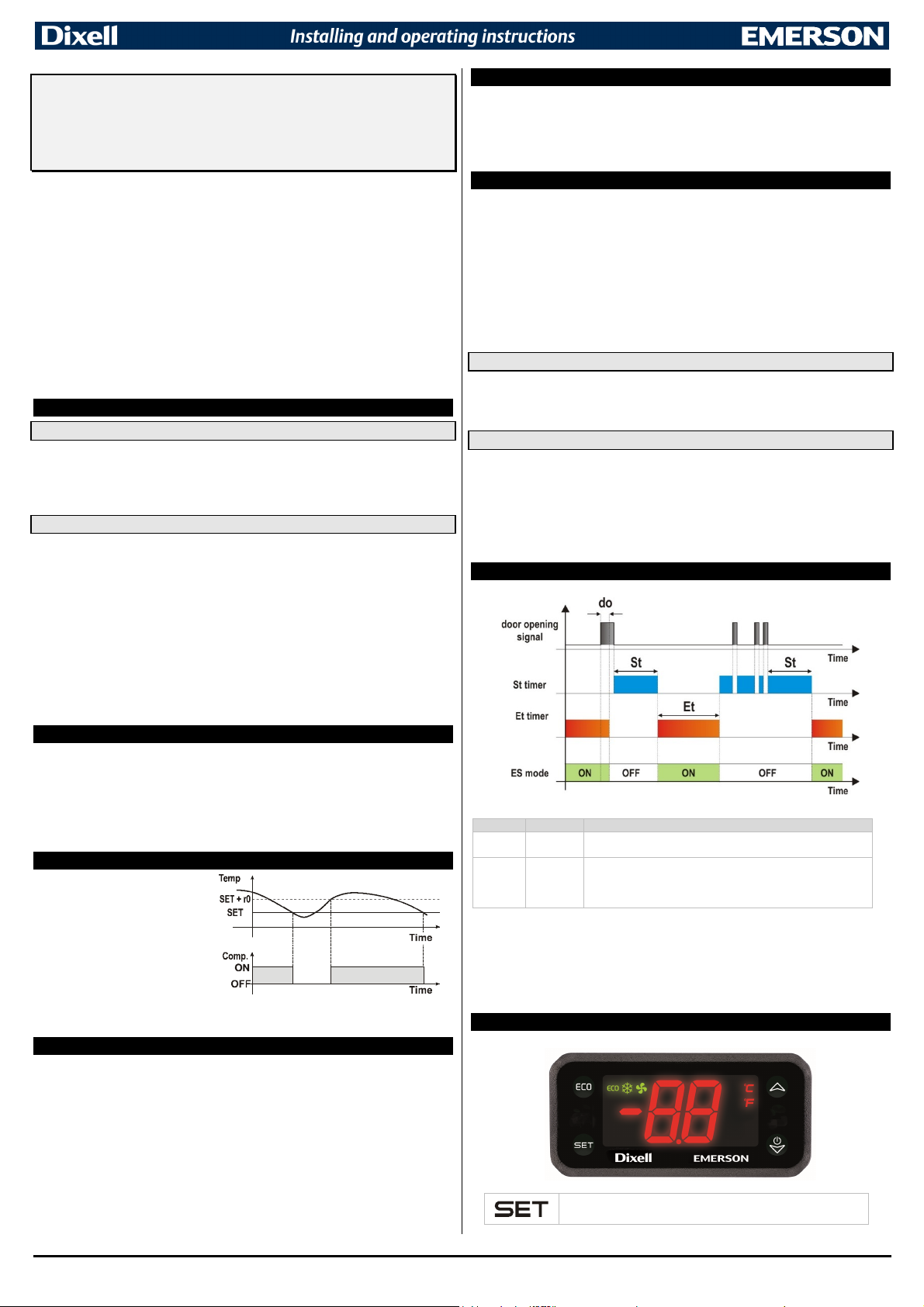
7 AUTOMATIC ENERGY SAVING FUNCTION
FROM TO CHANGED BY
Standard E.S.
E.S. Standard
NOTE: the cycles (ES → Standard mode → ES ….) are always operating with iF or 2F=do and Et and
St different from zero.
With Et or St=0 the controller doesn’t change the operating mode, and it’s possible to pass from the
standard mode to E.S. by using the ECO button or with iF or 2F=ES.
Note: the energy saving status is saved in EEPROM to resume previous operation if a power failure
occurs.
- Push the ECO button
- Door continuously closed for the Et time
- Push the ECO button
- Controller in ES mode for the St time
- If the controller is in ES and the door is open more than do time,
the controller restart standard set point.
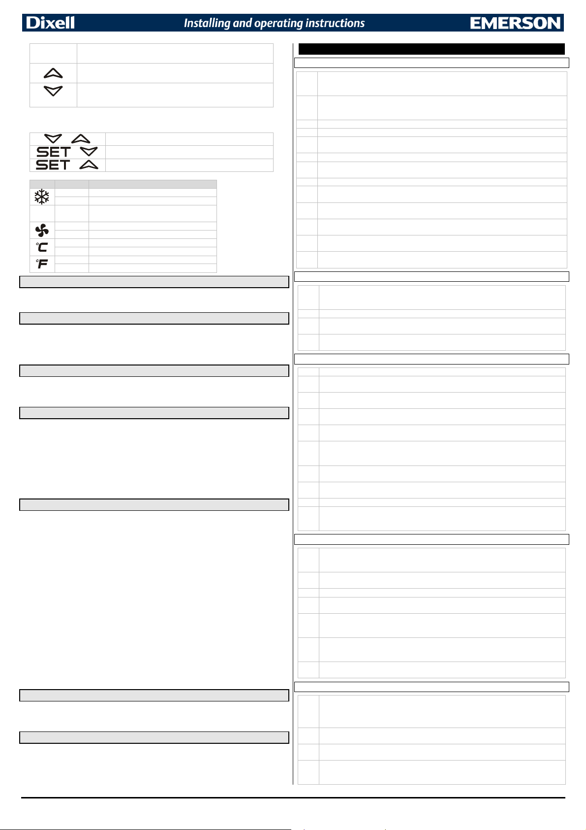
8 FRONT PANEL COMMANDS
To display target set point, in programming mode it selects a parameter or
confirm an operation.
1592033060 - XRB06-07CH GB r1.0 12.02.2018.docx XRB06CH – XRB07CH 1/5
Page 2
+
+
+
ECO (ECO) for light or energy saving mode activation/deactivation
(UP) In programming mode it browses the parameter codes or increases
the displayed value.
(DOWN/OFF) In programming mode it browses the parameter codes or
ONOFF
KEYS COMBINATION
LED MODE SIGNIFICATO
ECO On Energy Saving mode active
decreases the displayed value.
Keep it pressed for 3 sec for ON/OFF mode.
On Compressor running
Flashing Anti-short cycle delay enabled (AC parameter).
On Fans output enabled
Flashing Fans delay after defrost
On Measurement unit
Flashing Programming mode
On Measurement unit
Flashing Programming mode
To lock or unlock the keyboard
To enter in programming mode
To return to room temperature display
8.1 HOW TO SEE THE SET POINT
1. Push and immediately release the SET key, the set point will be showed;
2. Push and immediately release the SET key or wait for 3 sec to return to normal visualisation.
8.2 HOW TO CHANGE THE SETPOINT
1. Push the SET key for more than 3 sec to change the Set point value;
2. The value of the set point will be displayed and the “°C” or “°F” LED starts blinking;
3. To change the Set value push the UP or DOWN arrows.
4. To memorise the new set point value push the SET key again or wait for 10 sec.
8.3 HOW TO START A MANUAL DEFROST
A configurable button needs to be set as dE to activate the manual defrost control function. After that,
keep the DEF button pressed for the required time (immediate or 3 sec if timed) in order to activate a
defrost.
8.4 HOW TO CHANGE A PARAMETER VALUE
To change any parameter value, operate as follows:
1. Enter the Programming mode by pressing the SET+DOWN keys for 3 sec (“°C” or “°F” LED starts
blinking).
2. Select the required parameter. Press the SET key to display its value
3. Use UP or DOWN to change its value.
4. Press SET to store the new value and move to the following parameter.
To exit: Press SET+ UP or wait for 15 sec without pressing any key.
NOTE: the set value is stored even when the procedure is terminated by waiting for the time-out to
expire.
8.5 HIDDEN MENU
The hidden menu includes all the parameters of the instrument.
HOW TO ENTER THE HIDDEN MENU
1. Enter the Programming mode by pressing the SET+DOWN keys for 3 sec (“°C” or “°F” LED starts
blinking).
2. Released the keys and then push again the SET+DOWN keys for more than 7 sec. The “L2” label will
be displayed immediately followed from the Hy parameter.
NOW YOU ARE IN THE HIDDEN MENU.
3. Select the required parameter.
4. Press the SET key to display its value
5. Use UP or DOWN to change its value.
6. Press SET to store the new value and move to the following parameter.
To exit: Press SET+ UP or wait for 15 sec without pressing any key.
NOTE1: if there are no parameters in L1, after 3 sec the “nP” message will be displayed. Keep both keys
pushed till the “L2” message will be displayed.
NOTE2: the set value is stored even when the procedure is terminated by waiting for the time-out to
expire.
HOW TO MOVE A PARAMETER FROM THE HIDDEN MENU TO THE FIRST
LEVEL (AND VICEVERSA)
Each parameter present in the HIDDEN MENU can be removed or put into “THE FIRST LEVEL” (user
level) by pressing SET+DOWN. In HIDDEN MENU when a parameter is present in First Level the
decimal point is on.
8.6 TO LOCK THE KEYBOARD
1. Keep pressed for more than 3 sec the UP and DOWN keys.
2. The “OF” message will be displayed and the keyboard will be locked. If a key is pressed more
than 3 sec the “OF” message will be displayed.
8.7 TO UNLOCK THE KEYBOARD
Keep both UP and DOWN key pressed more than 3 sec until the “on” message will be displayed.
9 PARAMETERS
REGULATION
HY Differential in standard mode: (0.1 to 25°C; 1 to 45°F) differential for set point used in normal
mode. Compressor Cut IN is SET+HY. Compressor Cut OUT is when the temperature reaches
the set point SET.
HE Differential in energy saving mode: (0.1 to 25°C; 1 to 45°F) differential for set point used in
energy saving mode. Compressor Cut IN is SET_ES+HE. Compressor Cut OUT is when the
temperature reaches the set point SET_ES.
LS Minimum SET POINT: (-55°C to SET; -67°F to SET) sets the minimum value for the set point.
US Maximum SET POINT: (SET to 99°C; SET to 99°F) set the maximum value for set point.
ot First probe calibration: (-9.9 to 9.9°C; -17 to 17°F) allows to adjust possible offset of the first
probe.
P2 Evaporator probe presence: (n; Y) n=not present; Y=probe configured as present.
oE Second probe calibration: (-9.9 to 9.9°C; -17 to 17°F) allows to adjust possible offset of the
second probe.
P3 Third probe presence: (n; Y) n=not present; Y=probe configured as present.
F3 Third probe calibration: (-9.9 to 9.9°C; -17 to 17°F) allows to adjust possible offset of the
second probe.
od Outputs activation delay at start up: (0 to 99 min) this function is enabled at the initial start-
up of the instrument and inhibits any output activation for the period set in the parameter.
AC Anti-short cycle delay: (0 to 99 min) minimum interval between the compressor stop and the
following restart.
CY Compressor ON time with faulty probe: (0 to 99min) time during which the compressor is
active in case of faulty thermostat probe. With CY=0 compressor is always OFF.
Cn Compressor OFF time with faulty probe: (0 to 99min) time during which the compressor is
OFF in case of faulty thermostat probe. With Cn=0 compressor is always active.
DISPLAY
CF Measurement unit: (°C; °F) °C=Celsius; °F=Fahrenheit. WARNING: When the
measurement unit is changed the SET point and the values of the parameters Hy, LS, US, oE,
o1, AU, AL have to be checked and modified if necessary.
rE Resolution (only for °C): (dE; in) dE=decimal between -9.9 and 9.9°C; in=integer.
Ld Default display: (P1; P2; P3; P4; SP; dr) P1=thermostat probe; P2=evaporator probe;
P3=third probe; P4=not used; SP=Set point; dr=not used.
dy Display delay: (0 to 99 min) when the temperature increases, the display is updated of 1°C
or 1°F after this time.
DEFROST
td Defrost type: (EL; in) EL= electrical heater, compressor OFF; in=hot gas, compressor ON.
EA Automatic defrost: (n; Y) n=function disabled; Y=a defrost is automatically activated at the
beginning of any energy saving period.
PE Probe selection for first defrost: (nP; P1; P2; P3; P4) nP=not used, defrost ends by time;
P1=thermostat probe; P2=evaporator probe; P3=third probe; P4=not used.
dE Defrost termination temperature: (-55 to 50°C; -67 to 99°F) if P2=Y, this is the temperature
measured by the evaporator probe which causes the end of defrost.
id Interval between defrost cycles: (0 to 99 min) determines the time interval between two
consecutives defrosts cycles.
Md Maximum duration for first defrost: (0 to 99min, 0 means no defrost) when P2=n, (no
evaporator probe present, the defrost is) it sets the defrost duration, when P2=y (defrost end
based on temperature) it sets the maximum length for defrost.
dd Start defrosts delay: (0 to 99min) this is useful when different defrost start times are
necessary to avoid overloading the plant.
dF Display during defrost: (rt; it; SP; dF) rt=real temperature; it=start defrost temperature;
SP=SET-POINT; dF=label dF.
tA Delay for temperature visualization after defrost: 0 to 99 min.
dt Drip time: (0 to 99min) time interval between reaching defrost termination temperature and
the restoring of the control’s normal operation. This time allows the evaporator to eliminate
water drops that might have formed due to defrost.
FANS
FC Fans operating mode: (cn, on, cY, oY) cn=in runs with the compressor, OFF during defrost;
on=continuous mode, OFF during defrost; cY=runs with the compressor, ON during defrost;
oY=continuous mode, ON during defrost.
Fd Fans delay after defrost: (0 to 99 min) Interval between the end of a defrost operation and
the next evaporator fans start.
Ft Temperature differential for forced activation of fans: 0 to 50°C; 0 to 90°F.
FS Fans stop temperature: (-55 to 50°C; -67 to 99°F) setting of temperature, detected by
evaporator probe, above which fans are always OFF.
Fn Fan ON time: (0 to 15 min) with FC=Cn or CY, (fan activated in parallel with compressor). It
sets the evaporator fan ON cycling time when the compressor is off. With Fn=0 and FF≠0 the
fan are always off, with Fn=0 and FF=0 the fan are always off.
FF Fan OFF time: (0 to 15 min) with FC=Cn or CY, (fan activated in parallel with compressor). It
sets the evaporator fan off cycling time when the compressor is off. With Fn=0 and FF≠0 the
fan are always off, with Fn=0 and FF=0 the fan are always off.
FP Probe selection for fan management: nP = fan regulator is disabled; P1 = thermostat probe;
P2 = evaporator probe; P3 =configurable probe; P4 = Probe on Hot Key plug.
ALARMS
CA Temperature alarms configuration: (Ab; rE) Ab = absolute temperature: alarm temperature
is given by the AL or AU values. rE = temperature alarms are referred to the set point.
Temperature alarm is enabled when the temperature exceeds the SET+AU or SET-AL
values.
AU Maximum temperature alarm: (AL to 99°C; AL to 99°F) when this temperature is reached
the alarm is enabled, after the Ad delay time.
AL Minimum temperature alarm: (-55°C to AU; -67°F to AU) when this temperature is reached
the alarm is enabled, after the Ad delay time.
FH Differential for temperature alarm recovery: (0.1 to 25.5°C; 1 to 45°F) differential for
temperature alarm recovery. It’s also used for the restart of the fan when the FS temperature
is reached.
1592033060 - XRB06-07CH GB r1.0 12.02.2018.docx XRB06CH – XRB07CH 2/5
Page 3

Ad Temperature alarm delay: (0 to 99 min) time interval between the detection of an alarm
condition and alarm signalling.
dA Exclusion of temperature alarm at start-up: (0 to 99 min) time interval between the
detection of the temperature alarm condition after instrument power on and alarm signalling.
CONDENSER TEMPERATURE ALARMS
t2 Condenser alarm temperature probe: (nP; P1; P2; P3; P4) nP=not used, condenser alarm
is disabled; P1=thermostat probe; P2=evaporator probe; P3=third probe; P4=not used.
L2 Condenser low temperature alarm: (-55 to 99°C; -67 to 99°F) when this temperature is
reached the “L2” alarm is signalled after the r1+r2 delay.
U2 Condenser high temperature alarm: (-55 to 99°C; -67 to 99°F) when this temperature is
reached the “H2” alarm is signalled after the r1+r2 delay.
H2 Differential for temperature condenser alarm recovery: 0.1 to 25°C; 1 to 45°F
r1 Condenser temperature alarm delay: (0 to 99 min) time interval between the detection of
the condenser alarm condition and alarm signalling.
r2 Condenser temperature alarm exclusion at start up: 0 to 99 min.
bL Compressor off due low temperature alarm: n; Y
C2 Compressor off due high temperature alarm: n; Y
RELAYS
tb Alarm relay switched off by pushing a button: n; Y.
o1 First relay configuration: dF=defrost.; Fn=evaporator fan; AL=alarm; Li=light; Au=DO NOT
USE; nF=always on with instrument on; db=DO NOT USE; C2=DO NOT USE; d2=DO NOT
USE
o2 Second relay configuration: dF=defrost.; Fn=evaporator fan; AL=alarm; Li=light; Au=DO
NOT USE; nF=always on with instrument on; db=DO NOT USE; C2=DO NOT USE; d2=DO
NOT USE
o3 Third relay configuration: dF=defrost.; Fn=evaporator fan; AL=alarm; Li=light; Au=DO NOT
USE; nF=always on with instrument on; db=DO NOT USE; C2=DO NOT USE; d2=DO NOT
USE
AP Alarm output polarity: (CL; oP) CL=alarm relay will close in case of any alarm; oP=alarm
relay will open ain case of any alarm
ENERGY SAVING
Et Period to switch from Energy Saving to Standard mode with door closed: (0 to 99 hours)
if the door remains closed for the Et time, the controller automatically switch to the ES mode.
With Et=0 the cycle are disabled. For curtain application set iF or 2F=ES.
St Period to switch from Standard to Energy Saving mode with door closed: (0 to 99 hours)
if the door remains closed for the Et time the controller automatically switch from ES to
standard mode. With St=0 the cycle are disabled. For curtain application set iF or 2F=ES.
ES Temperature variation during the Energy Saving cycle: (-30.0°C to 30.0°C; -54 to 54°F)
sets the increasing value of the set point during the Energy Saving mode.
do Door open time before restoring the Standard mode: (0 to 99 min) if the door remains
open more than dS time, the controller switches from the ES to standard mode.
1H Overheating before activating the super cooling function in Standard mode: (0.0
to12.0°C; 0 to 21°F) value added to Set-Point SET to determine the activation temperature for
the sub-cooling cycle.
1S Subcooling for super cooling function in Standard mode: (0.0 to 12.0°C; 0 to 21°F) value
subtracted to Set-Point SET to determine the end temperature of sub-cooling cycle.
1t Maximum duration for super cooling function both for Standard and energy Saving
mode: (0 to 99 min) working period for super cooling function
2H Overheating before activating the super cooling function in Energy Saving mode: (0.0
to12.0°C; 0 to 21°F) value added to Set-Point SET to determine the activation temperature for
the sub-cooling cycle.
2S Subcooling for super cooling function in Energy Saving mode: (0.0 to 12.0°C; 0 to 21°F)
value subtracted to Set-Point SET to determine the end temperature of sub-cooling cycle.
LG Light off in ES mode: (n, Y) it sets if the light is switched off when the controller is in ES
mode.
DIGITAL INPUT
iP Digital input 1 polarity: (oP; cL) oP=activated by closing the contact; cL=activated by
opening the contact.
2P Digital input 2 polarity: (oP; cL) oP=activated by closing the contact; cL=activated by
opening the contact.
iF Digital input 1 configuration: (do; ES; CP; EL; bA; dF;AU; HC; Fn; PA; nu) do=door switch
function; ES=energy saving mode control; CP=compressor lock; EA=external warning alarm,
“EA” label is displayed; bA=external lock alarm, “CA” label is displayed; dF=defrost activation;
Au=not used; HC=inversion of the kind of action; Fn=remote fan activation; PA=external
pressure switch alarm, label “PA” is displayed; nu=not used.
2F Digital input 2 configuration: (do; ES; CP; EL; bA; dF;AU; HC; Fn; PA; nu) do=door switch
function; ES=energy saving mode control; CP=compressor lock; EA=external warning alarm,
“EA” label is displayed; bA=external lock alarm, “CA” label is displayed; dF=defrost activation;
Au=not used; HC=inversion of the kind of action; Fn=remote fan activation; PA=external
pressure switch alarm, label “PA” is displayed; nu=not used.
di Digital input 1 delay: (0 to 99min) with iF=EA, bA or PA: is the delay between the detection
of the external alarm condition and its signalling. With iF=do it represents the delay to activate
the door open alarm.
2d Digital input 2 delay: (0 to 99min) with 2F=EA, bA or PA: is the delay between the detection
of the external alarm condition and its signalling. With iF=do it represents the delay to activate
the door open alarm.
dC Compressor and fan status when open door: (no; Fn; cP; Fc) no=normal functioning;
Fn=Fan OFF; cP=Compressor OFF; Fc=Compressor and Fan OFF.
rd Regulation restart with door open alarm: (n; Y) n=no regulation if door is opened; Y=when
di is elapsed regulation restarts even if door open alarm is present.
Cd Stop Compressor delay: (0 to 99 min) set the time between the activation of the digital input
and the stop of the compressor when iF or 2F=CPr.
OTHER
bd ECO key configuration (immediate pressure): (dE; Li; Au; P2; ES) dE=defrost; Li=light;
Au=do not use; P2=probe P2 value visualisation; ES=energy saving mode
bn DOWN key configuration (immediate pressure): (nu; OF; ES; dE) nu=not used;
OF=ONOFF function; ES=energy saving mode; dE=defrost
1592033060 - XRB06-07CH GB r1.0 12.02.2018.docx XRB06CH – XRB07CH 3/5
b3 ECO key configuration (long pressure): (dE; Li; Au; P2; ES) dE=defrost; Li=light; Au=do
not use; P2=probe P2 value visualisation; ES=energy saving mode
b4 DOWN key configuration (long pressure): (nu; OF; ES; dE) nu=not used; OF=ONOFF
function; ES=energy saving mode; dE=defrost
d1 Thermostat probe display (read only)
d2 Evaporator probe display (read only)
d3 Third probe display (read only)
rS Real Set Point value (read only)
rL Software release
Pt Parameter code table
10 DIGITAL INPUTS
The available digital inputs are configurable by using iF and 2F parameters. They are placed as follows:
- Digital input 1 is in parallel to temperature probe P3. P3 present means that Digital Input 1 is
disabled.
- Digital input 2 is in parallel to temperature probe P2. P2 present means that Digital Input 2 is
disabled.
10.1 DOOR SWITCH (IF, 2F = DO)
It signals the door status and the corresponding relay output status through the dC parameter:
no = normal (any change);
Fn = Fan OFF;
CP = Compressor OFF;
FC = Compressor and fan OFF.
Since the door is opened, after the delay time set through parameter di, the door alarm is enabled, the
display shows the message dA and the regulation restarts if rd=Y. The alarm stops as soon as the
external digital input is disabled again. With the door open, the high and low temperature alarms are
disabled.
10.2 ENERGY SAVING (IF, 2F = ES)
The Energy Saving function allows to change the set point value as the result of the SET+HES
(parameter) sum. This function is enabled until the digital input is activated.
10.3 ENERGY SAVING (IF, 2F = CP)
Compressor will be locked if the input is active.
10.4 EXTERNAL ALARM (IF, 2F = EA)
After delay (di or 2d) the display will show the label EA and the outputs status will not change. The alarm
ends when the digital input is deactivated.
10.5 SERIOUS ALARM (IF, 2F = BA)
After delay (di or 2d) the display will show the label CA and the outputs status will be deactivated.
The alarm ends when the digital input is deactivated.
10.6 START DEFROST (IF, 2F = DF)
It starts a defrost if there are the requested conditions. After the defrost is finished, the normal regulation
will restart only if the digital input is disabled otherwise the instrument will wait until the Md safety time is
expired.
10.7 KIND OF ACTION: HEATING OR COOLING (IF, 2F = HC)
This function allows inverting the regulation of the controller: from cooling to heating and vice versa.
10.8 REMOTE FAN MANAGEMENT (IF, 2F = FN)
Remote fan management by using digital input.
10.9 PRESSURE SWITCH (IF, 2F = PA)
After delay (di or 2d) the display will show the label PA and the outputs status will be deactivated. The
alarm end:
- Automatically if the number of detected external events during the di or 2F period is lower than nS
- Manual if the number of detected external events during the di or 2F period is higher than nS
11 INSTALLATION AND MOUNTING
XRB06CH and XRB07CH shall be mounted on vertical panel, in a
29x71 mm hole, and fixed using the special bracket supplied.
The temperature range allowed for correct operation is 0 to 60°C.
Avoid places subject to strong vibrations, corrosive gases,
excessive dirt or humidity. The same recommendations apply to
probes. Let air circulate by the cooling holes.
12 ELECTRICAL CONNECTIONS
The instrument is provided with screw terminal block to connect cables with a cross section up to
2.5mm2. Before connecting cables make sure the power supply complies with the instrument’s
requirements. Separate the probe cables from the power supply cables, from the outputs and the power
connections. Do not exceed the maximum current allowed on each relay, in case of heavier loads use a
suitable external relay.
12.1 PROBES
The probes shall be mounted with the bulb upwards to prevent damages due to casual liquid infiltration. It
is recommended to place the thermostat probe away from air streams to correctly measure the average
room temperature. Place the defrost termination probe among the evaporator fins in the coldest place,
where most ice is formed, far from heaters or from the warmest place during defrost, to prevent
premature defrost termination.
Page 4

13 USE THE HOT KEY
13.1 HOW TO PROGRAM THE HOT KEY FROM THE INSTRUMENT
(UPLOAD)
Program a controller by using the keypad.
1. When the controller is ON, insert the “Hot Key” and push UP key.
2. The "uP" message will appear, followed a by a flashing “Ed” label.
3. Push SET key and the “Ed” will stop flashing.
4. Turn OFF the instrument, remove the “Hot Key” and then turn it ON again.
NOTE: the “Er” message will be displayed in case of a failed programming operation. In this case push
the UP key if you want to restart the upload again or remove the “Hot Key” to abort the operation.
13.2 HOW TO PROGRAM AN INSTRUMENT USING HOT KEY
(DOWNLOAD)
1. Turn OFF the controller.
2. Insert a programmed “Hot Key” into the 5-PIN plug and then turn the controller ON.
3. The parameter list present into the HOTKEY is automatically downloaded into the controller
memory. The “do” label will blink followed a by flashing “Ed”.
4. After 10 sec the controller restarts, loading the newer parameters.
5. Remove the “Hot Key”.
NOTE: the “Er” message is displayed in case of a failed copying operation. In this case turn the controller
off and then on again (if you want to retry the operation) or remove the “Hot Key” to end the operation.
14 ALARM SIGNALLING
Mess. Cause Outputs
P1 Room probe failure Compressor output according to CY e Cn
P2 Evaporator probe failure Defrost end is timed
P3 Third probe failure Outputs unchanged
HA Maximum temperature alarm Outputs unchanged
LA Minimum temperature alarm Outputs unchanged
H2 Maximum temperature alarm for condenser Outputs unchanged
L2 Minimum temperature alarm for condenser Outputs unchanged
EA External alarm Outputs unchanged
CA Serious external alarm All outputs OFF
PA Pressure switch alarm All outputs OFF
dA Door Open Depends on par. rd
14.1 ALARM RECOVERY
Probe alarms P1, P2 and P3 starts some seconds after the fault in the related probe; they automatically
stop some seconds after the probe restarts normal operation. Check connections before replacing the
probe. Temperature alarms “HA”, “LA”, “U2” and “L2” automatically stop as soon as the temperature
returns to normal values.
Alarms “EA” and “CA” (with iF=bL) recover as soon as the digital input is disabled.
15 TECHNICAL DATA
Housing: self-extinguishing ABS
Case: frontal 32x74 mm; depth 60mm
Mounting: panel mounting in a 71x29mm panel cut-out
Protection: IP20
Frontal protection: IP65
Connections: Screw terminal block 2.5 mm2 wiring
Power supply: (according to the model) 230Vac 10%, 50/60Hz; 110Vac 10%, 50/60Hz
Power absorption: 3.5VA max
Display: 2 digits, red LED, 14.2 mm high
Inputs: up to 3 NTC or PTC probes
Digital input: up to 2 free voltage contacts
Relay outputs:
Data storing: on the non-volatile memory (EEPROM)
Kind of action: 1B
Pollution degree: 2
Software class: A
Rated impulsive voltage: 2500V
Overvoltage Category: II
Operating temperature: 0T60°C (32T140°F)
Storage temperature: -25T60°C (-13T140°F)
Relative humidity: 20 to 85% (no condensing)
Measuring and regulation range:
Resolution: 0.1°C or 1°C or 1°F (selectable)
Accuracy (ambient temp. 25°C): ±0.1°C ±1 digit
Compressor: SPST 16(6) A 250Vac or 20(8) A 250Vac
Defrost: SPDT 8(3) A, 250Vac
AUX: SPST 8(3) A, 250Vac
Fan: SPST 5(2) A, 250Vac
NTC -40T110°C (-40T230°F)
PTC -40T150°C (-40T302°F)
16 CONNECTIONS
16.1 XRB06CH – 20+8+5A
16.2 XRB07CH – 16+8+8+5A
17 DEFAULT SETTING VALUES
LABEL DESCRIPTION RANGE DEFAULT
REGULATION
HY Differential in standard mode
HE Differential in energy Saving mode
LS Minimum Set Point value -55°C to SET; -67°F to SET -50.0°C
US Maximum Set Point value SET to 99°C; SET to 99°F 50.0°C
ot Thermostat probe calibration -9.9 to 9.9°C; -17 to 17°F 0.0
P2 Evaporator probe presence n; Y n
oE Evaporator probe calibration -9.9 to 9.9°C; -17 to 17°F 0.0
P3 Third probe presence n; Y n
F3 Third probe calibration -9.9 to 9.9°C; -17 to 17°F 0.0
od Outputs activation delay at start up 0 to 99 min 0
AC Anti-short cycle delay 0 to 99 min 2
CY Compressor ON time faulty probe 0 to 99 min 5
Cn Compressor OFF time faulty probe 0 to 99 min 10
DISPLAY
CF Measurement units °C; °F °C
rE Resolution (only for °C) dE; in dE
Ld Default Display P1; P2; P3; P4; SP; rt P1
dy Display delay 0 to 15 min 0
DEFROST
td Defrost type EL; in EL
EA Automatic defrost n; Y n
PE Defrost probe selection nP; P1; P2; P3; P4 P2
dE Defrost termination temperature -55 to 50°C; -67 to 99°F 8.0°C
id Interval between defrost cycles 0 to 99 hours 12
Md Maximum length for defrost 0 to 99 min 15
dd Start defrost delay 0 to 99 min 0
dF Display during defrost rt; in; SP; dF dE
Delay for temperature visualization after
tA
defrost
dt Draining time 0 to 99 min 2
1d Defrost enabled during super cooling n; Y n
FANS
FC Fans operating mode cn; on; cY; oY Cn
Fd Fans delay after defrost 0 to 99 min 2
0.1 to 25°C; 1 to 45°F
0.1 to 25°C; 1 to 45°F
0 to 99 min 0
2.0°C
2.0°C
1592033060 - XRB06-07CH GB r1.0 12.02.2018.docx XRB06CH – XRB07CH 4/5
Page 5

Temperature differential for forced
Ft
activation of fans
FS Fans stop temperature -55 to 50°C; -67 to 99°F 50.0°C
Fn Fan ON time 0 to 15 min 5
FF Fan OFF time 0 to 15 min 10
FP Probe selection for fan management nP; P1; P2; P3; P4 P2
ALARMS
CA Temperature alarm configuration Ab; rE Ab
AU Maximum temperature alarm ALL to 99°C; ALL to 99°F 99°C
AL Minimum temperature alarm -55°C to ALU; -67°F to ALU -40°C
Differential for temperature alarm
FH
recovery
Ad Temperature alarm delay 0 to 99 min 2
dA Exclusion of temperature alarm at startup 0 to 99 min 99
CONDENSER TEMPERATURE ALARMS
t2 Condenser alarm probe selection nP; P1; P2; P3; P4 nP
L2 Condenser low temperature alarm -55 to 99°C; -67°F to 99°F -1.0°C
U2 Condenser high temperature alarm -55°C to 99°C; -67°F to 99°F 45°C
Differential for condenser temperature
H2
alarm recovery
r1 Temperature alarm delay 0 to 99 min 5
Exclusion of temperature alarm after
r2
power-on
Compressor off due to condenser low
bL
temperature alarm
Condenser off due to condenser high
C2
DEFROST-LIGHT RELAY
temperature alarm
tb Alarm relay muting n; Y Y
o1 First relay configuration
o2 Second relay configuration
o3 (*) Third relay configuration
AP Alarm relay polarity CL; oP CL
ENERGY SAVING
Standard to ES mode time with door
Et
closed
ES to Standard mode time with door
St
closed
ES Differential for energy saving -30 to 30°C; -54 to 54°F 3
Door open time before restoring
do
Standard mode.
Overheating before activating super
1H
cooling function
1S Sub Cooling 0.1 to 25.0°C; 1 to 45°F 1.0
1t Maximum duration for super cooling 0 to 99 min 60
Overheating before activating super
2H
cooling function
2S Sub Cooling 0.1 to 25.0°C; 1 to 45°F 1.0
LG Light off in ES mode n; Y n
DIGITAL INPUTS
iP Digital input 1 polarity CL; oP CL
2P Digital input 2 polarity CL; oP CL
iF Digital input 1configuration
2F Digital input 2 configuration
di Digital input 1 alarm delay 0 to 99 min 2
2d Digital input 2 alarm delay 0 to 99 min 2
Number of activation of the pressure
nS
switch
Compressor and fan status when open
dC
door
rd Regulation with door open n; Y Y
Cd Stop compressor delay 0 to 15 min 0
OTHER
bd ECO key configuration (immediate) dE; Li; AU; P2; ES ES
bn DOWN key configuration (immediate) nu; OF; ES; dE nu
b3 ECO key configuration (timed) dE; Li; AU; P2; ES Li
b4 DOWN key configuration (timed) nu; OF; ES; dE oF
d1 Thermostat probe display Read Only - - -
d2 Evaporator probe display Read Only - - -
d3 Third probe display Read Only - - -
rS Real SETPOINT value Read Only - - -
rL Firmware release Read Only - - -
1592033060 - XRB06-07CH GB r1.0 12.02.2018.docx XRB06CH – XRB07CH 5/5
0 to 50°C; 0 to 90°F 0
0.1 to 25,5°C; 1 to 255°F 2.0
0.1 to 25°C; 1 to 45°F
0 to 99 min 99
n; Y n
n; Y n
dF; Fn; AL; Li; AU; nF; dB; C2;
dF; Fn; AL; Li; AU; nF; dB; C2;
dF; Fn; AL; Li; AU; nF; dB; C2;
do; ES; CP; EL; bA; dF; AU; HC;
do; ES; CP; EL; bA; dF; AU; HC;
d2
d2
d2
0 to 99 hours 4
0 to 99 hours 8
0 to 255 sec 3
0.1 to 25.0°C; 1 to 45°F 10
0.1 to 25.0°C; 1 to 45°F 10
Fn; PA; nu
Fn; PA; nu
0 to 15 15
no; Fn; cP; Fc Fn
5°C
Li
Fn
AL
do
EL
Pt Parameter code table Read Only - - -
(*) available only for XRB07CH
 Loading...