

Emerson Dixell XR75CX Series, Dixell XR75CX-110VAC, Dixell XR75CX-230VAC Installation And Operation Manual
Page 1

XR75CX Digital Controller for Medium-Low
Temperature Refrigeration Applications
Installation and Operation Manual
026-1210 Rev 4
Page 2

Page 3

Emerson
1065 Big Shanty Road NW, Suite 100
Kennesaw, GA 30144 USA
770-425-2724 •
www.emerson.com
Page 4

Page 5

Table of Contents
1 INTRODUCTION.......................................................................................................................................................... 1
1.1. G
ENERAL WARNING ..................................................................................................................................................... 1
2 OVERVIEW ................................................................................................................................................................... 1
2.1. G
ENERAL DESCRIPTION................................................................................................................................................ 1
2.2. O
RDERING CODE ......................................................................................................................................................... 1
3 CONTROLLING LOADS ............................................................................................................................................ 2
3.1. C
OMPRESSOR ................................................................................................................................................................ 2
3.2. D
EFROST ....................................................................................................................................................................... 2
3.3. C
ONTROL OF EVAPORATOR FANS ................................................................................................................................ 2
3.3.1. Forced Activation of Fans..................................................................................................................................... 2
3.3.2. Cyclical Activation of the Fans With Compressor Off.......................................................................................... 2
3.4. L
IGHT RELAY CONFIGURATION (PAR OA2; TERMINALS 1-2)..................................................................................... 3
3.4.1. Light Relay............................................................................................................................................................ 3
3.4.2. Auxiliary Relay – oA2=AUS .................................. ............................................................................................... 3
3.4.3. On/Off Relay (oA2=onF)...................................................................................................................................... 3
3.4.4. Neutral Zone Regulation ...................................................................................................................................... 3
3.4.5. Alarm Relay........................................................................................................................................................... 3
3.4.6. Night Blind Management During Energy Saving Cycles................................................ ...................................... 3
4 FRONT PANEL COMMANDS.................................................................................................................................... 4
4.1. K
EYS AND FUNCTIONS ................................................................................................................................................. 4
4.2. U
SE OF LEDS ............................................................................................................................................................... 4
5 MAX AND MIN TEMPERATURE MEMORIZATION........................................................................................... 5
5.1. H
OW TO SEE THE MIN TEMPERATURE ........................................................................................................................ 5
5.2. H
OW TO SEE THE MAX TEMPERATURE....................................................................................................................... 5
5.3. H
OW TO RESET THE MAX AND MIN TEMPERATURE RECORDED ................................................................................. 5
6 MAIN FUNCTIONS ...................................................................................................................................................... 6
6.1. H
OW TO SEE THE SETPOINT ......................................................................................................................................... 6
6.2. H
OW TO CHANGE THE SETPOINT.................................................................................................................................. 6
6.3. H
OW TO START A MANUAL DEFROST.......................................................................................................................... 6
6.4. H
OW TO CHANGE A PARAMETER VALUE..................................................................................................................... 6
6.5. T
HE HIDDEN MENU ...................................................................................................................................................... 6
6.5.1. How to Enter the Hidden Menu ............................................................................................................................ 6
6.5.2. How to Move a Parameter From the Hidden Menu To the First Level and Vice Versa...................................... 7
6.6. H
OW TO ASSIGN A MODBUS ADDRESS ..................................................................................................................... 7
6.7. H
OW TO LOCK THE KEYBOARD ................................................................................................................................... 7
6.8. T
O UNLOCK THE KEYBOARD ....................................................................................................................................... 7
6.9. T
HE CONTINUOUS CYCLE............................................................................................................................................. 7
6.10. T
HE ON/OFF FUNCTION ............................................................................................................................................ 7
7 PARAMETERS ............................................................................................................................................................. 8
8 DIGITAL INPUTS....................................................................................................................................................... 13
8.1. G
ENERIC ALARM (I2F=EAL) ..................................................................................................................................... 13
8.2. S
ERIOUS ALARM MODE (I2F=BAL)........................................................................................................................... 13
Table of Contents • i
Page 6

8.3. PRESSURE SWITCH (I2F=PAL) ................................................................................................................................... 13
8.4. D
OOR SWITCH INPUT (I1F OR I2F=DOR) .................................................................................................................... 13
8.5. S
TART DEFROST (I1F OR I2F=DEF)............................................................................................................................ 13
8.6. S
WITCH THE AUXILIARY RELAY (I2F=AUS) ............................................................................................................. 13
8.7. I
NVERSION OF THE KIND OF ACTION: HEATING - COOLING (I2F=HTR) .................................................................... 13
8.8. E
NERGY SAVING (I2F=ES) ......................................................................................................................................... 13
8.9. ON - OFF F
8.10. D
IGITAL INPUTS POLARITY....................................................................................................................................... 14
UNCTION (I2F=ONF)................................................................................................................................ 13
9 RS485 SERIAL LINE (FOR MONITORING SYSTEMS)...................................................................................... 15
10 X-REP OUTPUT (OPTIONAL)............................................................................................................................... 15
11 INSTALLATION AND MOUNTING ..................................................................................................................... 16
12 ELECTRICAL CONNECTIONS............................................................................................................................. 16
12.1. P
ROBE CONNECTION ................................................................................................................................................. 16
13 HOW TO USE THE HOT KEY ............................................................................................................................... 17
13.1. H
13.2. H
OW TO PROGRAM A HOT KEY FROM THE DEVICE (UPLOAD) ............................................................................... 17
OW TO PROGRAM THE DEVICE USING A HOT KEY (DOWNLOAD)......................................................................... 17
14 ALARM SIGNALS ................................................................................................................................................... 18
14.1. S
14.2. A
14.3. O
ILENCING BUZZER/ALARM RELAY OUTPUT........................................................................................................... 18
LARM RECOVERY ................................................................................................................................................... 18
THER MESSAGES .................................................................................................................................................... 18
15 SPECIFICATIONS.................................................................................................................................................... 19
16 CONNECTIONS ........................................................................................................................................................ 21
17 E2 MODBUS NETWORK WIRING ....................................................................................................................... 22
18 ECT MODBUS NETWORKING TO E2S............................................................................................................... 23
18.1. COM P
18.2. COM P
18.3. E2 S
ORT ASSOCIATIONS - E2 VERSIONS 3.XX AND BELOW ................................................................................ 23
ORT ASSOCIATIONS - E2 VERSIONS 4.2 AND ABOVE ................................................................................... 23
ETUP OF DEVICES .............................................................................................................................................. 24
18.3.1. Set Up Network Ports........................................................................................................................................ 24
18.3.2. Add and Connect the Device............................................................................................................................. 24
18.4. W
18.5. MODBUS T
IRING TYPES .......................................................................................................................................................... 25
ERMINATION BLOCKS ........................................................................................................................... 26
19 DEFAULT SETTING VALUES .............................................................................................................................. 27
APPENDIX A - ALTERNATE MODBUS COM WIRING METHOD FOR E2, XR, XM, AND XEV DEVICES 31
ii • XR75CX I&O Manual 026-1210 Rev 4
Page 7

1 Introduction
2Overview
1.1. General Warning
Please read the following safety precautions and warnings
before using this manual:
CAUTION!
• This manual is part of the product and
should be kept near the device for easy and
quick reference.
• The device should not be used for purposes
different from those described in this manual. It
cannot be used as a safety device.
• Check the application limits before proceeding.
SAFETY PRECAUTIONS AND
WARNINGS!
• Check that the supply voltage is correct
before connecting the device.
• Do not expose to water or moisture: use the
controller only within the operating limits and avoid
sudden temperature changes with high atmospheric
humidity to prevent condensation from forming.
• Warning! Disconnect all electrical connections
before performing any kind of maintenance.
• Fit the probe where it is not accessible by the end
user. The device must not be opened.
• In case of failure or faulty operation, send the
device back to the distributor or to Emerson (see
address) with a detailed description of the fault.
• Verify the maximum current that can be applied
to each relay (see Section 15, Specifications).
• Ensure that the wires for probes, loads, and the
power supply are separated and far enough from each
other without crossing or intertwining.
• In case of applications in industrial
environments, the use of main filters (our mod. FT1)
in parallel with inductive loads could be useful.
2.1. General Description
Model XR75CX (32 mm x 74 mm) is a microprocessor
based controller, suitable for applications on medium or
low temperature ventilated refrigeration units. It has four
(4) relay outputs to control compressor, fan, and defrost,
which can be either electrical or reverse cycle (hot gas) and
light (configurable).
It can also have up to four (4) NTC (EU or US type) probe
inputs. The first probe is used for temperature control. The
second probe is used to control the defrost termination
temperature at the evaporator. One of the two (2) digital
inputs can operate as a third temperature probe. The fourth
probe is used to control the condenser temperature (for
condenser alarm
management) or to display a temperature value. Set the
PbC parameter to CtC to support standard CPC
temperature sensors (factory default).
The RS-485 serial output enables the unit to be connected
to a network line that is MODBUS-RTU compatible, such
as the monitoring units of XWEB family. The Hot Key
receptacle allows the controller to be programmed by
means of the Hot Key programming keyboard.
The controller is fully configurable through special
parameters that can be easily programmed through the
keyboard.
2.2. Ordering Code
Device
Name
XR75CX -
110VAC
XR75CX -
230VAC
Table 2-1 - Product Ordering Code
Dixell Code
XR75CX-4C6F3B -
X0LG3OEUB4NA-000
XR75CX-5C6F3B -
X0LG3OEUB5NA-000
Emerson
Code
318-6030
318-6031
General Warning Introduction • 1
Page 8
3 Controlling Loads
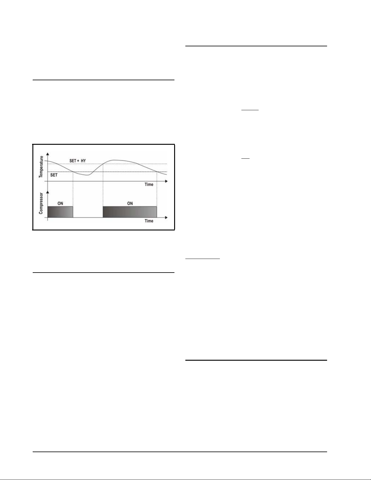
3.1. Compressor
The regulation is performed according to the temperature
measured by the thermostat probe with a positive
differential (HY) from the setpoint: if the temperature
increases and reaches setpoint plus the differential, the
compressor is started and then turned OFF when the
temperature reaches the setpoint value again.
3.3. Control of Evaporator Fans
The fan control mode is selected by means of the FnC
parameter:
• FnC = C_n: fans will switch ON and OFF with the
compressor and not run
• FnC = O_n: fans will run even if the compressor is
OFF, and not run during defrost.
After defrost, there is a timed fan delay allowing for
drip time, set by means of the Fnd parameter.
• FnC = C_y: fans will switch ON and OFF with the
compressor and run
• FnC = O_y: fans will run continuously during
defrost also.
An additional parameter called FSt provides the
setting of temperature, detected by the evaporator probe,
above which the fans are always OFF. This is used to make
sure that air is circulated only if this temperature is lower
than set in FSt.
3.3.1. Forced Activation of Fans
during defrost.
during defrost.
Figure 3-1 - Compressor Temperature Regulation
In case of a fault in the thermostat probe, the start and stop
of the compressor are timed through parameters Con and
CoF.
3.2. Defrost
Two defrost modes are available through the tdF
parameter: defrost through electrical heater (tdF=EL) and
hot gas defrost (tdF=in).
• EdF=in, the defrost is made every idF time (the
standard method for the controller)
Other parameters are used to control defrost cycles: its
maximum duration (MdF) and two defrost modes: timed or
controlled by the evaporator’s probe (P2P).
At the end of defrost dripping time is started, its
duration is set in the Fdt parameter. With Fdt=0, the
dripping time is disabled.
Managed by the Fct parameter, this function is
designed to avoid short cycles of fans that could occur
when the controller is switched ON or after a defrost, when
the room air warms the evaporator.
How it works: If the temperature difference between the
evaporator probe and the room probe is higher than the Fct
parameter value, the fans will be switched ON. When Fct
= 0, the function will be
disabled.
3.3.2. Cyclical Activation of the Fans With Compressor Off
When FnC = C-n or C-y (fans are working in parallel with
the compressor), by means of the Fon and FoF parameters,
the fans can carry out ON and OFF cycles even if the
compressor is switched OFF. When the compressor is
stopped, the fans will continue to work for the Fon time.
With Fon = 0, the fans always remain OFF when the
compressor is OFF.
3.4. Light Relay Configuration (PAR oA2; Terminals 1-2)
The functioning of the auxiliary relay (terminals
1-2) can be set by the oA2 parameter, according to the kind
of application needed. Possible settings are as follows:
2 • XR75CX I&O Manual 026-1210 Rev 4
Page 9

3.4.1. Light Relay
When oA2 = Lig, the relay 1-2 operates as a light.
3.4.2. Auxiliary Relay — oA2=AUS
a. Relay Activation By Digital Input 2 (oA2 = AUS,
i2F = AUS)
When oA2 = AUS a nd i2F = AUS, the relay 1-2 is switched
ON and OFF by the digital input.
b. Auxiliary Thermostat
An anti-condensing heater with the possibility of switching
it ON and OFF with the keyboard.
Parameters Involved
• ACH - The kind of regulation for the auxiliary relay:
Ht: heating; CL: cooling
• SAA - Setpoint for auxiliary relay
• SHY - Differential for auxiliary relay
• ArP - Probe for auxiliary relay
• Sdd - Auxiliary output OFF during defrost
The differential is set by the SHY parameter.
NOTE: Set oA2 =AUS and ArP= nP (no probe
for auxiliary output). In this case, the relay 1-2
can be activated only by the digital input with
i1F or i2F = AUS.
3.4.3. On/Off Relay (oA2=onF)
When oA2 = onF, the relay is activated when the controller
is turned ON and de-activated when the controller is turned
OFF.
3.4.4. Neutral Zone Regulation
When oA2 = db, the relay 1-2 can control a heater
element to perform a neutral zone action.
• oA2 cut in = SET-HY
• oA2 cut out = SET
3.4.5. Alarm Relay
When oA2 = ALr, the relay 1-2 operates as an alarm relay.
It is activated every time an alarm occurs. Its status depends
on the tbA parameter: if tbA = y, the relay is silenced by
pressing any key. If tbA = n, the alarm relay remains ON
until the alarm condition recovers.
3.4.6. Night Blind Management During Energy Saving Cycles
With oA2 = HES, the relay 1-2 operates to manage the
night blind: the relay is powered when the energy saving
cycle is activated by a digital input, front panel button.
Light Relay Configuration (PAR oA2; Terminals 1-2) Controlling Loads • 3
Page 10

4 Front Panel
Locks/Unlocks the keyboard
Commands
Figure 4-1 - XR75CX Front Panel
4.1. Keys and Functions
Table 4-1 shows the keys that are found on the front panel
of the XR75CX controller and their corresponding
functions:
To enter programming mode
Returns to room temperature display
Table 4-1 - XR75CX Front Panel Keys and Functions
4.2. Use of LEDS
Each LED function is described in Table 4-2:
LED Mode Function
ON Compressor enabled
Flashing Anti-short cycle delay enabled
ON Defrost enabled
Flashing Drip time in progress
ON Fans enabled
Flashing
ON An alarm is occurring
Fans delay after defrost in
progress.
Key Function
Press to display target setpoint, to select a
parameter in programming mode, or to
confirm an operation
Starts a manual defrost
Press the UP arrow key to see the MAX
stored temperature, to browse the
parameter codes in programming mode,
or to increase the displayed temperature
value.
Press the DOWN arrow key to see the
MIN temperature, to browse the
parameter codes in programming mode,
or to decrease the displayed temperature
value.
Switches the device ON and OFF, if
onF = oFF
Switches the light ON and OFF, if oA1 =
Lig
Table 4-1 - XR75CX Front Panel Keys and Functions
ON Continuous cycle is running
ON Energy saving enabled
ON Light ON
ON Auxiliary relay ON
ON Measurement unit
Flashing Programming phase
Table 4-2 - LEDs
4 • XR75CX I&O Manual 026-1210 Rev 4
Page 11

5 Max and Min
Temperature
Memorization
5.1. How to See the MIN Temperature
1. Press and release the DOWN button.
2. The Lo message will be displayed followed
by the minimum temperature recorded.
3. By pressing the DOWN button again or by
waiting five seconds, the normal display will
be restored.
5.2. How to See the MAX Temperature
1. Press and release the UP button.
2. The Hi message will be displayed followed
by the maximum temperature recorded.
3. By pressing the UP button again or by
waiting 5 seconds, the normal display will be
restored.
5.3. How to Reset the Max and Min Temperature Recorded
1. Press and hold the SET button for more than
3 seconds while the max or min temperature
is displayed (rSt message will be displayed).
2. After confirming the operation, the rSt
message will start blinking and then the
normal temperature will be displayed.
How to See the MIN Temperature Max and Min Temperature Memorization • 5
Page 12
6 Main Functions
6.1. How to See the Setpoint
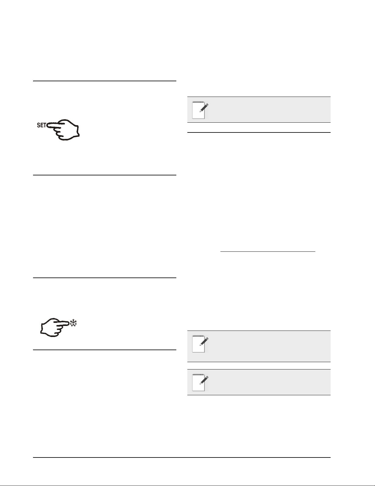
1.Press and immediately release the
SET key: the display will show the
setpoint value.
2. Press and immediately release the SET key or
wait for 5 seconds to display the probe value
again.
6.2. How to Change the
3. Use the UP or DOWN buttons to change its
value.
4. Press SET to store the new value and move to
the next parameter.
To exit: Press the SET + UP buttons or wait 15 seconds
without pressing a key.
NOTE: The set value is stored even when the
time-out expires and ends the procedure.
6.5. The Hidden Menu
The hidden menu includes all the parameters of the
controller.
6.5.1. How to Enter the Hidden Menu
Setpoint
1. Press and hold the SET button for more than
2 seconds to change the setpoint value.
2. The value of the setpoint will be displayed
and the °C or °F LED will start blinking.
3. To change the setpoint value, press the UP or
DOWN buttons within 10 seconds.
4. To memorize the new setpoint value, press
the SET key again or wait 10 seconds.
6.3. How to Start a Manual Defrost
Press and hold the DEF ke y f or mo re
than 2 seconds and a manual defrost
will start.
6.4. How to Change a Parameter Value
To change a parameter value, follow these steps:
1. Enter the Programming mode by pressing the
SET + DOWN buttons for 3 seconds (the °C
or °F LED will start blinking).
1. Enter the Programming mode by pressing the
SET + DOWN buttons for three (3) seconds
(the °C or °F LED will start blinking).
2. Release the buttons and then push the SET +
DOWN buttons for more than seven (7)
seconds. The Pr2 label will be displayed
immediately followed by the HY parameter:
You can now browse the Hidden Menu
3. Select the required parameter.
4. Press the SET button to display its value.
5. Use the UP or DOWN buttons to change its
value.
6. Press SET to store the new value and move to
the next parameter.
To exit: Press SET + DOWN or wait 15 seconds without
pressing a key.
NOTE: If no parameter is present in Pr1 menu,
after three (3) seconds the noP message is
displayed. Keep the keys pressed until the Pr2
message is displayed.
NOTE: The set value is stored even when the
time-out expires and ends the procedure.
.
2. Select the required parameter. Press the SET
button to display its value.
6 • XR75CX I&O Manual 026-1210 Rev 4
Page 13

6.5.2. How to Move a Parameter From the Hidden Menu To the First Level and Vice Versa
Each parameter present in the Hidden Menu (Pr2) can be
moved into the user level (Pr1) by pressing SET + DOWN
buttons. If a parameter is part of the user level, when it
appears in the Hidden Menu, the decimal point will be
illuminated.
6.9. The Continuous Cycle
When a defrost is not in progress, it can be activated by
pressing and holding the UP button for about 3 seconds.
The compressor operates to maintain the CCS setpoint for
the time set through the CCt parameter. The cycle can be
terminated before the end of the set time using the same
activation button (UP button for 3 seconds).
6.6. How to Assign a MODBUS Address
1. Follow steps 1 and 2 of Section 6.5.1., How
to Enter the Hidden Menu to access the
Hidden Menu.
2. Select the Adr parameter.
3. Press SET to select.
4. Choose the address number using the buttons
and press SET again to save.
5. Press SET and UP buttons to exit.
Note that devices cannot have duplicate addresses on the
network. Assigning MODBUS addresses prior to
terminating the network and leaving the address of device
1 as unused until the network is connected can prevent
duplicate addressing network issues.
6.7. How to Lock the Keyboard
1. Keep the UP + DOWN buttons pressed for
more than 3 seconds.
2. The PoF message will be displayed and the
keyboard will be locked. At this point it will
be possible to see the setpoint or the MAX or
Min temperature stored only.
3. If a button is pressed for more than 3 seconds
the PoF message will be displayed.
6.10.The ON/OFF Function
When onF = oFF, pressing the ON/OFF key
will switch OFF the controller. The OFF
message is displayed. In this configuration, the
regulation is disabled.
To switch the controller ON, press the ON/
OFF key again.
WARNING! Loads connected to the normally
closed contacts of the relays are always
supplied and under voltage (powered up), even
if the device is in stand-by mode.
6.8. To Unlock the Keyboard
Press and hold the UP and DOWN buttons for more than 3
seconds until the Pon message displays.
How to Assign a MODBUS Address Main Functions • 7
Page 14

7 Parameters
Code Parameter Function
REGULATION
(0.1 to 25.5°C; 1 to 45°F) Intervention differential for setpoint.
HY Differential
LS Minimum setpoint
US Maximum setpoint
ot Thermostat probe calibration
P2P Evaporator probe presence
oE Evaporator probe calibration
P3P Third probe presence (P3)
o3 Third probe calibration (P3)
P4P Fourth probe presence (n; Y) n = Not present; Y = present
o4 Fourth probe calibration
odS Outputs activation delay at start up
AC Anti-short cycle delay
rtr
CCt
CCS Setpoint for continuous cycle
Con
CoF
Percentage of the second and first
probe for regulation
Compressor ON time during
continuous cycle
Compressor ON time with faulty
probe
Compressor OFF time with faulty
probe
Com pr essor Cu t IN is Se t Point + d iffer en tial ( HY). Compressor
Cut OUT is when the temperature reaches the setpoint.
(-50°C to SET; -58°F to SET) Sets the minimum value for the
setpoint.
(SET to 110°C; SET to 230°F) Sets the maximum value for
setpoint.
(-12.0 to 12.0°C; -21 to 21°F) Allows to adjust possible offset of
the thermostat probe.
(n; Y) n = not present, the defrost stops by time; Y = pre sent, the
defrost stops by temperature.
(-12.0 to 12.0°C; -21 to 21°F) Allows to adjust possible offset of
the evaporator probe.
(n; Y) n = not present, the terminals 18-20 operate as digital
input; Y = present, the terminals 18-20 operate as third probe.
(-12.0 to 12.0°C; -21 to 21°F) Allows to adjust possible offset of
the third probe.
(-12.0 to 12.0°C; -21 to 21°F) Allows to adjust possible offset of
the fourth probe.
(0 to 255min) This function is enabled at the initial start up of
the instrument and inhibits any output activation for the period
of time set in the parameter.
(0 to 50min) Minimum interval between the compressor stop
and the following restart.
(0 to 100; 100=P1, 0=P2) Allows to set the regulation according
to the percentage of the first and second probe, as for the
following formula (rtr(P1-P2)/100 + P2).
(0.0 to 24h00min, res. 10min) Allows to set the length of the
continuous cycle. Compressor stays ON without interruption
during CCt time. This is useful, for instance, when the room is
filled with new products.
(-50 to 110°C; (-58 to 230°F) Sets the setpoint used during the
continuous cycle.
(0 to 255min) Time during which the compressor is active in
case of faulty thermostat probe. With Con=0 compressor is
always OFF.
(0 to 255min) Time during which the compressor is OFF in case
of faulty thermostat probe. With CoF=0 compressor is always
active.
DISPLAY
Table 7-1 - List of Parameters
8 • XR75CX I&O Manual 026-1210 Rev 4
Page 15

Code Parameter Function
(°C; °F) °C = Celsius; °F = Fahrenheit.
CF Temperature measurement unit
CAUTION: When the measurement unit is changed the SET
point and the values of the parameters HY, LS, US, ot, ALU and
ALL have to be checked and modified (if necessary).
rES Resolution (for °C) (in=1°C; dE=0.1°C) Allows decimal point display.
(P1; P2, P3, P4, SET, dtr) Selects which probe is displayed by
the instrument. P1 = Thermostat probe; P2 = Evaporator probe;
Lod Instrument display
P3 = Third probe (only for model with this option enabled); P4
= Fourth probe, SET = setpoint; dtr = percentage of
visualization.
(P1; P2, P3, P4, SET, dtr) Selects which probe is displayed by
rEd X-REP display (optional)
X- REP. P1 = Thermostat probe; P2 = Evaporator probe; P3 =
Third probe (only for model with this option enabled); P4 =
Fourth probe, SET = setpoint; dtr = percentage of visualization.
dLY Display delay
dtr
Percentage of the second and first
probe for visualization when Lod=dtr
(0 to 20min00s; res. 10s) When the temperature increases, the
display is updated of 1°C or 1°F after this time.
(0 to 99; 100=P1, 0=P2) If Lod=dtr, it allows to set the
visualization according to the percentage of the first and second
probe, as for the following formula (dtr(P1-P2)/100 + P2).
DEFROST
tdF Defrost type (EL; in) EL = electrical heater; in = hot gas
(nP; P1; P2; P3; P4) nP = no probe; P1 =thermostat probe; P2 =
dFP Probe selection for defrost termination
evaporator probe; P3 =configurable probe; P4 = Probe on Hot
Key plug
(-50 to 50°C; -58 to 122°F) (enabled only when EdF=Pb) Sets
dtE Defrost termination temperature
the temperature measured by the evaporator probe, which
causes the end of defrost.
idF Interval between defrost cycles
(0 to 120hours) Determines the interval of time between two
defrost cycles.
(0 to 255min) When P2P=n, (not evaporator probe: timed
MdF (Maximum) length for defrost
defrost) it sets the defrost duration. When P2P=Y (defrost end
based on temperature) it sets the maximum length for defrost.
dSd Start defrost delay
dFd Temperature displayed during defrost
dAd MAX display delay after defrost
(0 to 99min) This is useful when different defrost start times are
necessary to avoid overloading the plant.
(rt; it; SEt; dEF) rt = r eal tem pe ratur e; it = temp er ature at defros t
start; SEt = setpoint; dEF = “dEF” label.
(0 to 255min) Sets the maximum time between the end of
defrost and the restarting of the real room temperature display.
(0 to 120min) Time interval between reaching defrost
Fdt Drip time
termination temperature and the restoring of the control’s
normal operation. This time allows the evaporator to eliminate
water drops that might have formed due to defrost.
dPo First defrost after start-up (n; Y) n = after the idF time, Y = immediately
dAF Defrost delay after continuous cycle
(0.0 to 24h00min, res. 10min) Time interval between the end of
the fast freezing cycle and the following defrost related to it.
FANS
Table 7-1 - List of Parameters
The ON/OFF Function Parameters • 9
Page 16

Code Parameter Function
(C-n; o-n; C-Y; o-Y) C-n = runs with the compressor, OFF
FnC Fans operating mode
during defrost; o-n = continuous mode, OFF during defrost; CY = runs with the compressor, ON during defrost; o-Y =
continuous mode, ON during defrost.
Fnd Fans delay after defrost
Fct
Temperature differential to avoid fan
short cycles
FSt Fans stop temperature
(0 to 255min) Interval between end of defrost and evaporator
fans start.
(0 to 59°C; 0 to 90°F) (N.B.: if Fct=0 function disabled) If the
difference of temperature between the evaporator and the room
probes is higher than Fct value, the fans will be switched ON.
(-50 to 50°C; -58 to 122°F) Setting of temperature, detected by
evaporator probe, above which fans are always OFF.
(0 to 15min) With FnC=C_n or C_Y, (fan activated in parallel
with compressor) it sets the evaporator fan ON cycling time
Fon Fan ON time
when the compressor is OFF. With Fon=0 and FoF≠0 the fan
are always OFF, with Fon=0 and FoF=0 the fan are always
OFF.
(0 to 15min)
With FnC=C_n or C_Y, (fan activated in parallel with
FoF Fan OFF time
compressor) it sets the evaporator fan OFF cycling time when
the compressor is OFF.
With Fon=0 and FoF≠0 the fan are always OFF, with Fon=0
and FoF=0 the fan are always OFF.
(nP; P1; P2; P3; P4) nP = no probe; P1 =thermostat probe; P2 =
FAP Probe selection for fan management
evaporator probe; P3 =configurable probe; P4 = Probe on Hot
Key plug.
AUXILIARY THERMOSTAT CONFIGURATION (terms. 1-2) - oA2 = AUS
ACH Kind of regulation for auxiliary relay (Ht; CL) Ht = heating; CL = cooling
SAA Set Point for auxiliary relay
(-50 to 110.0°C; -58 to 230°F) It defines the room temperature
setpoint to switch auxiliary relay.
(0.1 to 25.5°C; 1 to 45°F) Intervention differential for auxiliary
SHY Differential for auxiliary output
output setpoint.
ACH=CL, AUX Cut in is [SAA+SHY]; AUX Cut out is SAA.
ACH=Ht, AUX Cut in is [SAA–SHY]; AUX Cut out is SAA.
(nP; P1; P2; P3; P4) nP = no probe, the auxiliary relay is
ArP Probe selection for auxiliary
switched only by the digital input; P1 = Probe 1 (Thermostat
probe); P2 = Probe 2 (evaporator probe); P3 = Probe 3 (display
probe); P4 = Probe 4
Sdd Auxiliary relay OFF during defrost
(n; Y) n = the auxiliary relay operates during defrost; Y = the
auxiliary relay is switched OFF during defrost
ALARMS
(nP; P1; P2; P3; P4) nP = no probe, the temperature alarms are
ALP Probe selection for alarm
disabled; P1 = Probe 1 (Thermostat probe); P2 = Probe 2
(evaporator probe); P3 = Probe 3 (display probe); P4 = Fourth
probe
(Ab; rE) Ab = absolute temperature, alarm temperature is given
ALC Temperature alarms configuration
by the ALL or ALU values. rE = temperature alarms are
referred to the setpoint. Temperature alarm is enabled when the
temperature exceeds the [SET+ALU] or [SET-ALL] values.
Table 7-1 - List of Parameters
10 • XR75CX I&O Manual 026-1210 Rev 4
Page 17

Code Parameter Function
ALU MAXIMUM temperature alarm
ALL Minimum temperature alarm
AFH
Differential for temperature alarm
recovery
ALd Temperature alarm delay
dAo
Exclusion of temperature alarm at
start-up
(ALL to 110°C; ALL to 230°F) When this temperature is
reached the alarm is enabled, after the ALd delay time.
(-50°C to ALU; -58 to ALU) When this temperature is reached
the alarm is enabled, after the ALd delay time.
(0.1 to 25.5°C; 1 to 45°F) Intervention differential for recovery
of temperature alarm
(0 to 255 min) Time interval between the detection of an alarm
condition and alarm signaling.
(0.0 to 24h00min, res. 10min) Time interval between the
detection of the temperature alarm condition after instrument
power ON and alarm signaling.
CONDENSER TEMPERATURE ALARM
AP2
Probe selection for temperature alarm
of condenser
AL2 Low temperature alarm of condenser
Au2 High temperature alarm of condenser
AH2
Differential for temperature condenser
alarm recovery
Ad2 Condenser temperature alarm delay
dA2
bLL
AC2
Condenser temperature alarm
exclusion at start up
Compressor OFF with low
temperature alarm of condenser
Compressor OFF with high
temperature alarm of condenser
(nP; P1; P2; P3; P4) nP = no probe; P1 =thermostat probe; P2 =
evaporator probe; P3 =configurable probe; P4 = Probe on Hot
Key plug
(-50 to 110°C; -58 to 230°F) When this temperature is reached
the LA2 alarm is signalled, possibly after the Ad2 delay.
(-50 to 110°C; -58 to 230°F) When this temperature is reached
the HA2 alarm is signalled, possibly after the Ad2 delay.
(0.1 to 25.5°C; 1 to 45°F)
(0 to 255 min) Time interval between the detection of the
condenser alarm condition and alarm signaling.
(0.0 to 24h00min, res. 10min)
(n; Y) n = no: compressor keeps on working; Y = yes,
compressor is switched OFF until the alarm is present, in any
case regulation restarts after AC time at minimum.
(n; Y) n = no: compressor keeps on working; Y = yes,
compressor is switched OFF until the alarm is present, in any
case regulation restarts after AC time at minimum.
AUXILIARY RELAY
(n; Y) n = silencing disabled: alarm relay stays ON until alarm
condition lasts; Y =silencing enabled: alarm relay is switched
OFF by pressing a key during an alarm.
tbA
Alarm relay silencing (with oA2
=ALr)
(dEF; FAn; ALr; LiG; AUS; onF; db; CP2; dEF2; HES) dEF =
defrost; FAn = do not select it; ALr = alarm; LiG = light; AUS
oA2 Second relay configuration (1-2)
= Auxiliary relay; onF = always ON with instrument ON; db =
neutral zone; CP2 = do not select it; dEF2 = do not select it;
HES = night blind
(CL; oP) it set if the alarm relay is open or clo sed when an alarm
AoP Alarm relay polarity
occurs. CL = terminals 1-2 closed during an alarm; oP =
terminals 1-2 open during an alarm.
DIGITAL INPUTS
i1P Digital input polarity (18-20)
(oP; CL) oP = the digital input is activated by opening the
contact; CL = the digital input is activated by closing the contact
Table 7-1 - List of Parameters
The ON/OFF Function Parameters • 11
Page 18

Code Parameter Function
i1F Digital input configuration (18-20)
i2P Second digital input polarity (18-19)
(dor; dEF) dor = door switch function; dEF = activation of a
defrost cycle
(oP; CL) oP = the digital input is activated by opening the
contact; CL = the digital input is activated by closing the contact
(EAL; bAL; PAL; dor; dEF; ES; AUS; Htr; FAn; HdF; onF)
EAL = external alarm: “EA” message is displayed; bAL =
serious alarm “CA” message is displayed; PAL = pressure
i2F
Second digital input configuration
(18-19)
switch alarm, “CA” message is displayed; dor = door switch
function; dEF = activation of a defrost cycle; ES = energy
saving; AUS = auxiliary relay activation with oA2=AUS; Htr =
type of inverting action (cooling or heating); FAn = fan; onF =
to switch the controller OFF
(0 to 255 min) Delay between the detection of the external alarm
did
Digital input alarm delay (18-20)
when i2F=EAL or i2F=bAL
condition and its signaling.
When i2F= PAL, it is the interval of time to calculate the
number of pressure switch activation
doA Door open signaling delay (0 to 255 min)
(0 to 15) Number of activation, during the did interval, before
nPS Number of pressure switch activation
signaling an alarm event (i2F=PAL).
If the nPS activation during did time is reached, switch OFF and
ON the instrument to restart normal regulation.
odc
Fan/compressor status when door
open
rrd Outputs restart after doA alarm
HES
Delta temperature during an Energy
Saving cycle
(no; FAn; CPr;F_C;) - no = normal; FAn = fan OFF; CPr =
compressor OFF, F_C = fan and compressor OFF
(n; Y) n = outputs not affected by the doA alarm; Y = outputs
restart with the doA alarm
(-30.0 to 30.0°C; -54 to 54°F)
Sets the increasing value of the setpoint [SET+HES] during the
Energy Saving cycle.
OTHER
Adr Serial address
(1 to 247) Identifies the instrument address when connected to a
MODBUS compatible monitoring system.
(ntC, CtC) It allows to set the kind of probe used by the
PbC Type of probe
instrument: ntC = NTC-EU probe, CtC = NTC-US probe. Set
this PbC parameter to CtC to support standard CPC temp
sensors - factory default.
onF ON/OFF key enabling (nU; oFF; ES) nU = disabled; oFF = enabled; ES = not set it
dP1 Thermostat probe display
dP2 Evaporator probe display
dP3 Third probe display (optional)
dP4 Fourth probe display
rSE Real setpoint
Shows the setpoint used during the energy saving cycle or
during the continuous cycle.
rEL Software release for internal use
Ptb Parameter table code Read only
Table 7-1 - List of Parameters
12 • XR75CX I&O Manual 026-1210 Rev 4
Page 19

8 Digital Inputs
The first digital input 18-20 is enabled with P3P = n.With
P3P = n and i1F = i2F, the second digital input is disabled.
The free voltage digital inputs are programmable by the i1F
and i2F parameters.
8.5. Start Defrost (i1F or i2F=dEF)
A defrost will start if the right conditions exist. After the
defrost is finished, normal regulation will restart only if the
digital input is disabled; otherwise, the controller will wait
until the MdF safety time is expired.
8.1. Generic Alarm (i2F=EAL)
As soon as the digital input is activated the unit will wait
for did time delay before signaling the EAL alarm
message. The outputs status don’t change. The alarm stops
just after the digital input is de-activated.
8.2. Serious Alarm Mode (i2F=bAL)
When the digital input is activated, the unit will wait for
did delay before signaling the CA alarm message. The
relay outputs are switched OFF. The alarm will stop as
soon as the digital input is deactivated.
8.3. Pressure Switch (i2F=PAL)
If the pressure switch has reached the number of activations
(cycles) of the nPS parameter during the interval time set
by the did parameter, the CA pressure alarm message will
be displayed. The compressor and the regulation are
stopped. When the digital input is ON the compressor is
always OFF.
If the nPS activation in the did time is reached, switch the
controller OFF and ON to restart normal regulation.
8.6. Switch the Auxiliary Relay (i2F=AUS)
When oA2 = AUS, the digital input switches the status of
the auxiliary relay.
8.7. Inversion of the Kind of
Action: Heating Cooling (i2F=Htr)
This function allows to invert the regulation of the
controller: from cooling to heating and vice versa.
8.8. Energy Saving (i2F=ES)
The Energy Saving function allows the setpoint value to be
changed as the result of the [SET+ HES] (parameter) sum.
This function is enabled until the digital input is activated.
8.9. ON - OFF Function (i2F=onF)
Switches the controller ON and OFF.
8.4. Door Switch Input (i1F or i2F=dor)
This input signals the door status and the corresponding
relay output status through the odc parameter: no = normal
(any change); Fan = Fan OFF; CPr = Compressor OFF;
F_C = Compressor and fan OFF. Since the door is opened,
after the delay time set through parameter doA, the door
alarm is enabled, the display shows the message dA, and
the regulation restarts is rtr=Y. The alarm stops as soon as
the external digital input is disabled again. With the door
open, the high and low temperature alarms are disabled.
Generic Alarm (i2F=EAL) Digital Inputs • 13
8.10.Digital Inputs Polarity
The digital input polarity depends on the i1P and i2P
parameters.
• i1P or i2P = C L: the input is activated by closing the
contact.
• i1P or i2P = OP: the input is activated by opening
the contact
Page 20

9 RS485 Serial Line
10 X-REP Output
(For Monitoring
Systems)
The RS485 serial line allows the controller to connect to a
monitoring system (MODBUS-RTU compatible) such as
the X-WEB500/3000/300.
(Optional)
Optionally, an X-REP can be connected to the controller
through the dedicated connector
Figure 10-1 - X-REP Output
To connect the X-REP to the controller, the following
connectors must be used: CAB-51F(1m), CAB-52F (2m),
CAB-55F (5m).
.
14 • XR75CX I&O Manual 026-1210 Rev 4
Page 21
11 Installation and
12 Electrical
Mounting
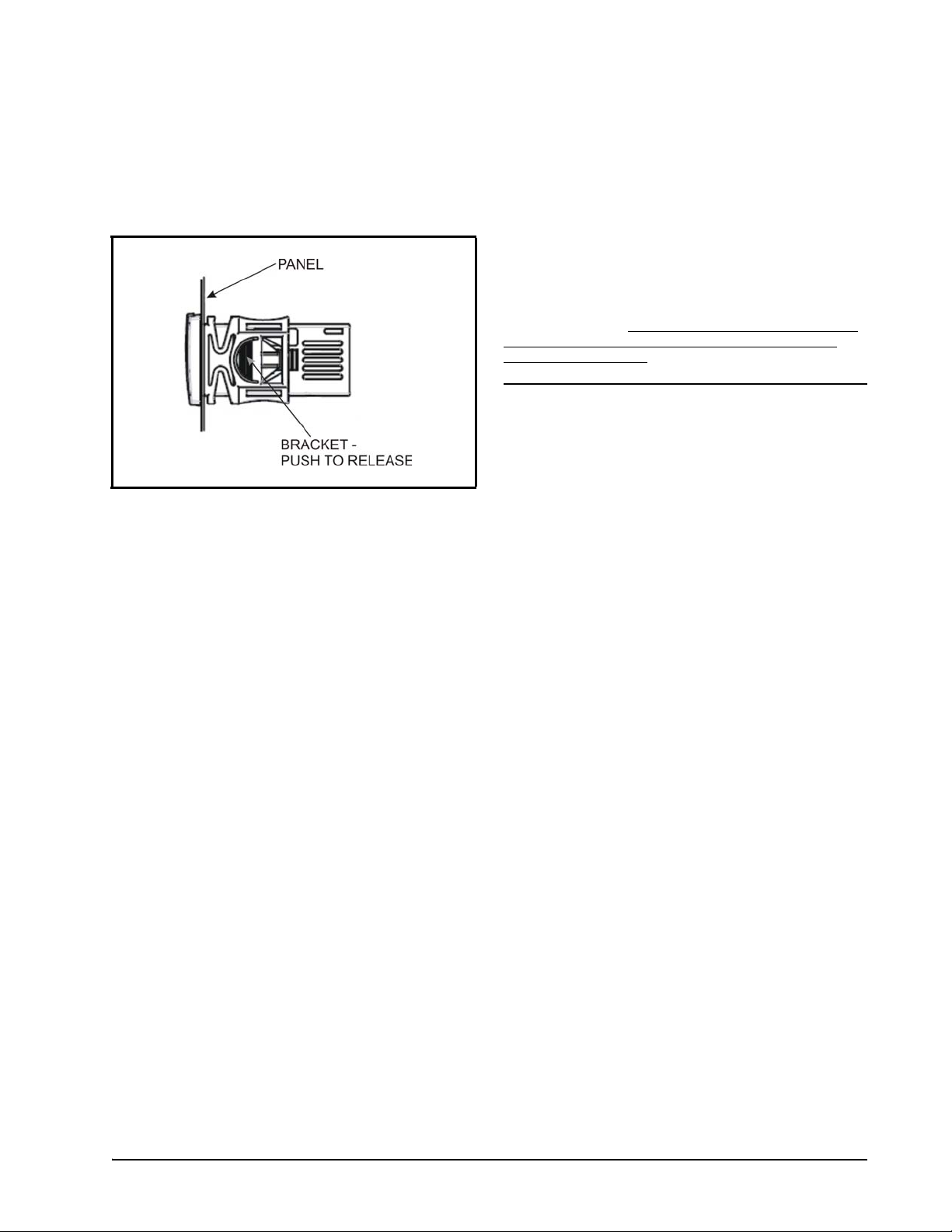
Figure 11-1 - Installation and Mounting of XR75CX
The XR75CX controller should be mounted on a vertical
panel, in a 29 mm x71 mm hole, and secured using the
special bracket supplied.
The temperature range allowed for correct operation is 0 to
60°C. Avoid places subject to strong vibrations, corrosive
gases, excessive dirt, or humidity. The same
recommendations apply to probes. Allow air to circulate
through the cooling holes.
Connections
The device is provided with screw terminal block to
connect cables with a cross section up to 2.5 mm2. Before
connecting cables verify that the power supply complies
with the device’s requirements. Separate the probe cables
from the power supply cables, from the outputs and the
power connections.
allowed on each relay, in case of heavier loads use a
suitable external relay.
12.1.Probe Connection
The probes should be mounted with the bulb upwards to
prevent damages due to casual liquid infiltration. It is
recommended the thermostat probe be placed away from
air streams to measure the average room temperature
correctly. Place the defrost termination probe among the
evaporator fans in the coldest place, (where most ice is
formed) and far from heaters or from the warmest place
during defrost to prevent premature defrost termination.
Do not exceed the maximum current
Probe Connection Installation and Mounting • 15
Page 22

13 How to Use the
Hot Key
13.1.How to Program a Hot Key From the Controller (Upload)
1. Program one controller using the front
keypad.
2. When the controller is ON, insert the Hot Key
into the 5-pin receptacle and push the up
arrow button; the uPL message appears
followed by a flashing End LED.
3. Push the SET button and End will stop
flashing to indicate the upload has been
successful.
4. Turn OFF the controller, remove the Hot
Key, then turn it ON again.
followed by End at the end of the data
transfer phase if the controller is programmed
correctly.
4. After 10 seconds the controller will restart
and work with the new parameters.
5. Remove the Hot Key.
NOTE: The Err message is displayed in case of
an error or failure in programming. In this
case turn the unit OFF and then ON if you
want to restart the download again or remove
the Hot Key to abort the operation.
NOTE: The Err message is displayed in case of
an error or failure in programming. In this
case, push the UP button again if you want to
restart the upload or remove the Hot Key to
abort the operation.
13.2.How to Program the Controller Using a Hot Key (Download)
1. Turn OFF the controller by pressing the on/
off button for 5 seconds. OFF will
display.
2. Insert a programmed Hot Key into the 5-pin
receptacle and then turn the Controller ON by
pressing the on/off button again for 5
seconds. The normal temperature value will
display to indicate the controller is ON.
3. Automatically, the parameter list of the Hot
Key is downloaded into the controller
memory; the doL message will display
16 • XR75CX I&O Manual 026-1210 Rev 4
Page 23

14 Alarm Signals
Message Cause Outputs
Compressor output
P1 Room probe failure
P2
P3 Third probe failure Outputs unchanged
P4
HA
LA
HA2
LA2
dA Door open Compressor restarts
EA External alarm Output unchanged.
CA
CA
rtF
Evaporator probe
failure
Fourth probe
failure
Maximum
temperature alarm
Minimum
temperature alarm
Condenser high
temperature
Condenser low
temperature
Serious external
alarm (i2F=bAL)
Pressure switch
alarm (i2F=PAL)
Real time clock
board failure
acc. to par. Con and
CoF
Defrost end is timed
Outputs unchanged
Outputs unchanged.
Outputs unchanged.
It depends on the
AC2 parameter
It depends on the
bLL parameter
All outputs OFF.
All outputs OFF
Alarm output ON;
Other outputs
unchanged;
Defrosts according
to par. idF. Contact
the service.
14.2.Alarm Recovery
Probe alarms P1, P2, P3, and P4 start some seconds after
the fault in the related probe; they automatically stop some
seconds after the probe restarts normal operation. Check
connections before replacing the probe.
Temperature alarms HA, LA, HA2, and LA2
automatically stop as soon as the temperature returns to
normal values.
Alarms EA and CA (with i1F = bAL) recover as soon as
the digital input is disabled.
Alarm CA (with i1F = PAL) recovers only by switching
OFF and ON the device.
14.3.Other Messages
Message Output
Pon Keyboard unlocked
PoF Keyboard locked
In programming mode:
noP
Table 14-2 - Additional Display Messages
No parameter is present
On the display or in dP2, dP3, dP4:
The selected probe is not enabled
Table 14-1 - Alarm Signals
14.1. Silencing Buzzer/Alarm Relay Output
If tbA = Y, the buzzer and the relay are silenced by
pressing any key.
If tbA = n, only the buzzer is silenced while the alarm relay
is ON until the alarm condition recovers.
Silencing Buzzer/Alarm Relay Output Alarm Signals • 17
Page 24

15 Specifications
Case:
Dimensions
Housing Self extinguishing ABS
Protection IP 20
Frontal Protection IP65
Front: 32 mm x 74 mm
Depth: 60 mm
Panel Mount: 71 mm x 29 mm panel cut-out
Connections
Power Supply
(depending on the model)
Power Absorption 3VA max
Display 3 digits, red LED, 14.2 mm high
Inputs
Relay Outputs
UL Ratings
Data Storing On the non-volatile memory (EEPROM)
Internal Clock Back-up 24 hours
Kind of Action 1B
Pollution Degree 2
Software Class A
Rated Impulsive Voltage 2500V
Overvoltage Category II
Temperatures
Screw terminal block ≤ 2.5 mm2 wiring
24VAC ±10%
230VAC ±10%, 50/60Hz
110VAC ±10%, 50/60Hz
Up to four (4) NTC-EU or NTC-US probes
Digital: free voltage contact
Evaporator Fan:
120/240 V, 50/60 Hz, 1/4 HP, 30k cycles
125 V, 50/60 Hz, 1/3 HP, 6k cycles
250 V, 50/60 Hz, 1/2 HP, 30k cycles
Compressor:
120 V, 50/60 Hz, 1/4 HP, 30k cycles
240 V, 50/60 Hz, 1/2 HP, 30k cycles
AUX/Light:
120/240 V, 50/60 Hz, 5 A General Purpose, 6k cycles
Defrost N. O.:
120/240 V, 50/60 Hz, 10 A, Resistive, 30k cycles
120/240 V, 50/60 Hz, C300, Pilot Duty, 30k cycles
Defrost N.C.:
120/240 V, 50/60 Hz, 10 A, Resistive, 30k cycles
120/240 V, 50/60 Hz, C300, Pilot Duty, 30k cycles
Operating: 0 to 55°C (32 to 131°F)
Storage: -30 to 85°C (-22 to 185°F)
Terminals 4 and 1
Terminals 3 and 1
Terminals 2 and 1
Terminals 7 and 1
Terminals 8 and 1
Table 15-1 - XR75CX Technical Data
18 • XR75CX I&O Manual 026-1210 Rev 4
Page 25

Relative Humidity 20 to 85% (no condensing)
Measuring and Regulation
Range
NTC-EU probe (10k ±1%, =3435): -40 to 110°C (-40 to 230°F)
NTC-US probe (xxk ±y%, =????): -40 to 110°C (-40 to 230°F)
Resolution 0.1°C or 1°C or 1°F (selectable)
Accuracy
(ambient temperature 25°C)
Table 15-1 - XR75CX Technical Data
±0.7°C ±1 digit
Other Messages Specifications • 19
Page 26

16 Connections
Figure 16-1 - XR75CX Connections
20 • XR75CX I&O Manual 026-1210 Rev 4
Page 27

17 E2 MODBUS Network Wiring
100 Ohm
½ Watt
Shield
Shield
Shield
EARTH GROUND CONNECTION
MODBUS TERMINATION
BLOCK 535-2711 150 ohm
Terminate last device only
COM4
REVERSE POLARITY OF +/- ON RS-485
CABLE FROM E2 TO DEVICE
*Note that for E2 Enhanced PIB
boards, the RS-485 connection
can be wired on COM 2, COM 4,
or COM 6 port.
• Connect the MODBUS Network to the RS485 Connector on the E2 PIB board (Belden 8641 recommended).
• Note to wire the RS485 +/- polarity at the E2 in the reverse
• Position the three termination jumpers to the UP (terminated) position to provide RS485 termination at the E2.
• Do not connect the shield of the MODBUS network to the E2 PIB center terminal. Instead, use a 100 ohm 1/2 watt
resistor to connect the MODBUS cable shield to earth ground.
• At each XR75CX device, wire the MODBUS cable to the RS485 +/- terminals and connect the MODBUS shield to
the pin 18 terminal.
• Terminate the end of the MODBUS network at the last XR75CX device on the daisy chain with the MODBUS
termination block (P/N 535-2711), or by connecting a 150 ohm resistor between the MODBUS +/- terminals.
of the XR75CX devices.
Figure 17-1 - XR75CX to E2 MODBUS Network Wiring
(Technical Bulletin P/N 026-4148).
Refer to Appendix A - Alternate MODBUS COM Wiring Method for E2, XR, XM, and XEV Devices
Other Messages E2 MODBUS Network Wiring • 21
Page 28
18 ECT MODBUS
E2 PIB COM PORT ASSOCIATIONS
COM1
COM4
COM6
COM2
Serial Device
RS485 COM Port
(2 Connectors)
RS485 COM Card
(2 Connectors)
Serial Device
RS232 Port
POWER INTERFACE BOARD
(PIB)
E2 Modem/Expansion
COM Card Mounted
Above PIB
Plug-In
Modem
Card
COM3
E2 Enclosure (Right Side)
RS485
RS232
E2
XR75CX
#1
TERMINATED,
BIASED
(ALL 3 JUMPERS
IN UP POSITION)
XR75CX
#1 #2
#3
XR75CX
XR75CX
E2 PIB COM PORT ASSOCIATIONS
COM1
Serial Device
RS232 Port
POWER INTERFACE BOARD
(PIB)
E2 Enclosure (Right Side)
COM2 COM6
COM4
Serial Device
RS485 COM Ports
Plug-In
Modem
Card
COM3
Networking to
E2s
18.1.COM Port Associations
- E2 Versions 3.xx and
Below
configured in E2 General Services
(,
Serial tab) to enable COM4 or an E2 Expansion COM
Card (P/N 637-4871) to enable COM6.
Connect the MODBUS network cable to the three-terminal
connector on the COM port you wish to assign as
MODBUS. Reverse polarity of +/- on RS485 cable from
E2 to the device.
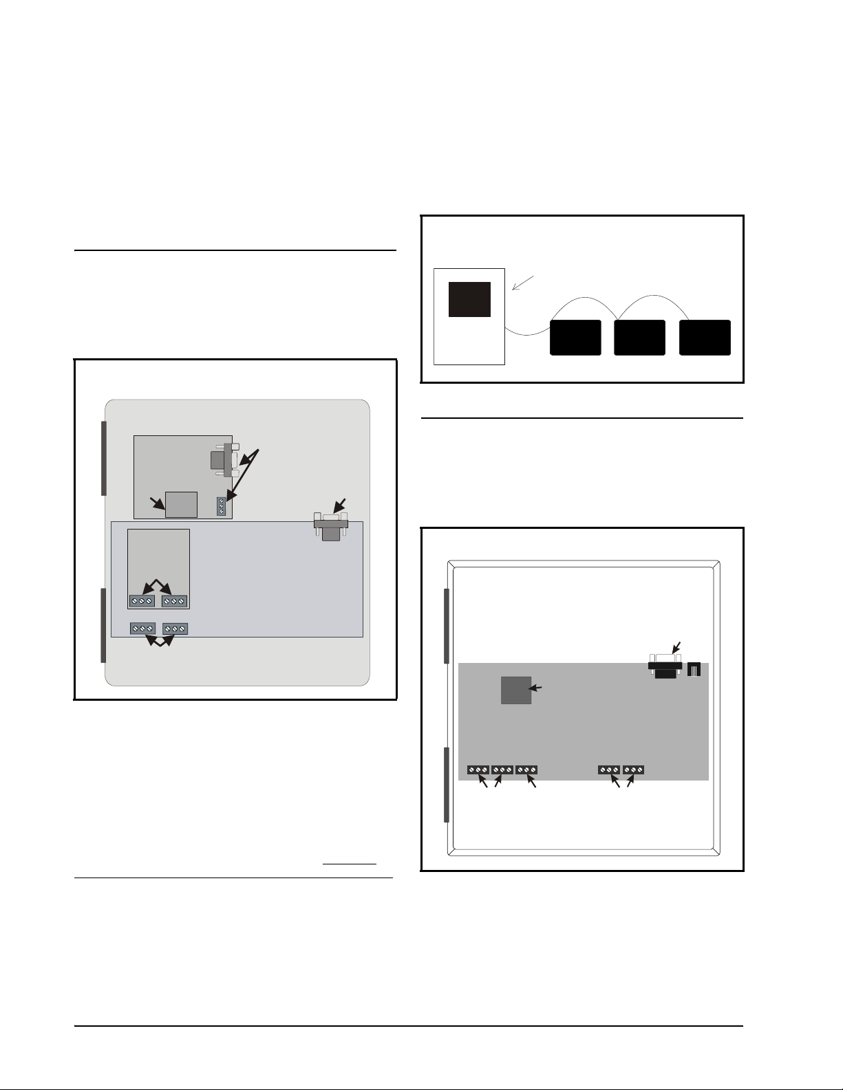
Figure 18-2 - MODBUS Networking
18.2.COM Port Associations
- E2 Versions 4.2 and
Above
Figure 18-1 - Location of E2 COM Ports (E2 versions 3.xx and
Below)
Connecting a XR75CX controller to an E2 requires the E2
to be version 2.84 or above. Contact Emerson for upgrade
information if the controller is a version before 2.84.
An E2 has up to three COM ports that can be assigned for
MODBUS communication: COM2, an RS485 port on the
E2 power interface board, and COM4 and COM6, which
are optional ports requiring expansion cards.
recommended for MODBUS connection of XR75CX units.
COM ports can only be used for one function; in other
words, if COM2 is set up as the I/O network, you cannot
connect MODBUS devices to COM2. Ensure your E2 is
equipped with an RS485 COM Card (P/N 637-4890) and
22 • XR75CX I&O Manual 026-1210 Rev 4
COM4 is
Figure 18-3 - Location of E2 COM Ports - E2 PIB Board (E2
versions 4.2 and above)
An E2 has three COM ports that can be assigned for
MODBUS communication (COM2). COM ports can only
be used for one function; in other words, if COM2 is set up
Page 29

as the I/O network, you cannot connect MODBUS devices
to COM2. Ensure your E2 is configured in E2 General
Services (, Serial tab) to enable COM4 or
COM6.
18.3.E2 Setup of Devices
rate.)
• Data Size - Leave this field at the default value (8).
• Parity - Leave this field at the default value (None).
• Stop Bits - Leave this field at the default value (1).
6. Press
to save changes and exit.
18.3.1.Set Up Network Ports
Before setting up a device, the port on the E2 that has the
MODBUS cable connected must be set up as a MODBUS
port.
1. Log in to the E2 with Level 4 access.
2. Press
3. Press
followed by - General
Controller Info.
+ to open the Serial tab of the General
Controller Info setup screens:
18.3.2.Add and Connect the Device
To enable communications between E2 and the XR75CX
units, the devices must be added and addressed in E2.
1. Log in to the E2 with Level 4 access.
2. Press
- Connected I/O Boards
and Controllers.
Figure 18-5 - Num Network Ctrls: NetSetup Screen
Figure 18-4 - Serial Communications Manager Screen
4. This screen will have a “Connection” field for all
COM ports on the E2. Highlight the COM port
connection field that will be used for the device, and
press - LOOK UP. From the list of network
types, select MODBUS.
5. Four fields will become visible underneath the
COM port connection field, which pertain to the
way the device communicates:
• Baud - Default setting is 19.2k. The baud rate
setting should be set to match the baud rate of the
XR75CX device (9600). (All devices connected to
the same COM port should be set to the same baud
E2 Setup of Devices ECT MODBUS Networking to E2s • 23
3. In the Num Network Ctrls: NetSetup screen, under
the ECT tab, enter the number of devices in the
Quantity field. (Max shows the maximum number
of devices allowed on the network.)
4. Press
5. Locate the units you added to the network list (press
to return to the Network Setup menu,
then select
- Network Summary.
and to scroll through the list). If desired,
enter a new name for each device in the Name field.
Page 30

Figure 18-6 - Network Summary Screen
6. By default, each device in the network list has a
board number of 0. To set the address and begin
communication, choose the device and press .
In the list of MODBUS devices, choose the address
number corresponding to the XR75CX address set
up through the front display, and press
select it. A window will open where you can specify
the address of the controller. If a network ID has
already been selected, its name will be shown next
to the network ID in this list. If the network ID you
are trying to assign has already been used, you must
set the address on this device to a different number
that is not being used.
to
8. When finished, press
Setup menu, then press
(Figure 18-6). Locate the devices you set up, and
look at each device’s status in the Status field. You
will see one of the following messages:
• Online - The device is communicating normally.
• Offline - The device is not communicating, has not
been commissioned, is not functional, or is not
powered up. Verify the device is powered up, wired
correctly, and has the proper network address, baud
rate, and parity.
• Unknown - The device is not communicating or has
not been commissioned. Verify the device is
powered up, wired correctly, and has the proper
network address, baud rate, and parity.
• No Port - No port is set up in the E2 Serial
Configuration Manager to be a MODBUS port.
• Wrong FW Rev - This message is likely caused by
the device having a firmware version older than the
minimum revision required by E2 for
communication. Replace the device with a new one
or a device that has the latest version of firmware on
it.
to return to the Network
- Network Summary
Figure 18-8 - Network Summary Screen
18.4.Wiring Types
Emerson specifies Belden #8761 shielded twisted pair
cables for use as MODBUS wiring (or Belden #82761 and
Belden #88761 for plenum installations).
Figure 18-7 - List of MODBUS Devices
7. Repeat Steps 5 and 6 until each device has a name
and address.
24 • XR75CX I&O Manual 026-1210 Rev 4
For MODBUS network wiring of XR75CX controllers to
E2, Belden #8641 (Emerson P/N 135-8641) is the
recommended wire type to use.
Page 31

If the recommended cable is not available in your area, be
SHIELD WIRE
(CONNECT TO
OF LAST DEVICE)
PIN 18
FROM OTHER
DEVICES
TO LAST DEVICE
AT END OF DAISY
CHAIN
sure the wiring meets or exceeds the following specs:
Shielded? Yes
Conductor Type Twisted Pair
Gauge 18 - 24 AWG
Capacitance between
signal wires
Capacitance between
signal and shield
31 pF/ft or less
(9.45 m) or less
59 pF/ft or less
(17.98 m) or less
4000 ft/18 to 22 AWG
Maximum Length
(1219.2 m)
2500 ft/24 AWG
(762 m)
Nominal Impedance 120W±50W
18.5.MODBUS Termination Blocks
Because the XR75CX device has no on-board means of
termination, use the MODBUS termination block (P/N
535-2711) for termination that can be wired to the end of
the cable segment using the three-pin connector. Wire the
two signal wires to the outside terminals, and connect the
shield to pin 18 of the device, keeping the exposed shield
wire length as short as possible (3 inches ideal maximum
length).
Figure 18-9 - MODBUS Termination Block (P/N 535-2711)
MODBUS Termination Blocks ECT MODBUS Networking to E2s • 25
Page 32

19 Default Setting Values
Label Name Range Value Level
SEt Setpoint LS to US
HY Differential
LS Minimum setpoint
US Maximum setpoint
ot Thermostat probe calibration
P2P Evaporator probe presence n=not present; Y=pres. Y Pr1
oE Evaporator probe calibration
P3P Third probe presence n=not present; Y=pres. n Pr2
o3 Third probe calibration
P4P Fourth probe presence n=not present; Y=pres. n Pr2
o4 Fourth probe calibration
odS Outputs delay at start up 0 to 255 min 0 Pr2
AC Anti-short cycle delay 0 to 50 min 1 Pr1
rtr P1-P2 percentage for regulation 0 to 100 (100=P1, 0=P2) 100 Pr2
CCt Continuous cycle duration 0.0 to 24h 00min, res. 10min 0.0 Pr2
CCS Setpoint for continuous cycle
Con
CoF
CF Temperature measurement unit °C; °F [°C] [°F] Pr2
rES Resolution in=integer; dE= dec.point dE Pr1
Lod Probe displayed P1; P2 P1 Pr2
rEd
dLY Display temperature delay 0.0 to 20min 00s, res. 10s 0.0 Pr2
dtr P1-P2 percentage for display 1 to 99 50 Pr2
tdF Defrost type EL=el. heater; in= hot gas EL Pr1
dFP
Compressor ON time with faulty
probe
Compressor OFF time with faulty
probe
2
X-REP display P1; P2; P3; P4; SEt; dtr P1 Pr2
Probe selection for defrost
termination
[0.1 to 25.5°C]
[1 to 255°F]
[-50°C to SET]
[-58°F to SET]
[SET to 110°C]
[SET to 230°F]
[-12 to 12°C]
[-21 to 21°F]
[-12 to 12°C]
[-21 to 21°F]
[-12.0 to 12.0°C]
[-21 to 21°F]
[-12.0 to 12.0°C]
[-21 to 21°F]
[-50 to 110.0°C]
[-58 to 230°F]
0 to 255 min 15 Pr2
0 to 255 min 30 Pr2
nP; P1; P2; P3; P4 P2 Pr2
[-5.0°C]
[23°F]
[2.0°C]
[2°F]
[-50.0°C]
[-58°F]
[110.0°C]
[230°F]
[0.0°C]
[0°F]
[0.0°C]
[0°F]
[0.0°C]
[0°F]
[0.0°C]
[0°F]
[-5°C]
[23°F]
- - -
Pr1
Pr2
Pr2
Pr1
Pr2
Pr2
Pr2
Pr2
Table 19-1- XR75CX Default Setting Values (2Only for XR75CX with X-REP output)
26 • XR75CX I&O Manual 026-1210 Rev 4
Page 33

Label Name Range Value Level
dtE Defrost termination temperature
[-50 to 50°C]
[-50 to 122°F]
[8°C]
[46°F]
Pr1
idF Interval between defrost cycles 1 to 120 hours 6 Pr1
MdF (Maximum) length for defrost 0 to 255 min 30 Pr1
dSd Start defrost delay 0 to 99 min 0 Pr2
dFd Displaying during defrost rt, it, SEt, DEF it Pr2
dAd MAX display delay after defrost 0 to 255 min 30 Pr2
Fdt Draining time 0 to 120 min 0 Pr2
dPo First defrost after start-up n=after idF; Y=immed. n Pr2
dAF Defrost delay after fast freezing 0 to 24h 00min, res. 10min 0.0 Pr2
FnC Fan operating mode C-n; o-n; C-Y; o-Y o-n Pr1
Fnd Fan delay after defrost 0 to 255 min 10 Pr1
FCt
Differential of temperature to force
fan activation
FSt Fan stop temperature
[0 to 50°C]
[0 to 90°F]
[-50 to 50°C]
[-58 to 122°F]
[10°C]
[10°F]
[36°C]
[23°F]
Pr2
Pr1
Fon Fan on time with compressor off 0 to 15 min 0 Pr2
FoF Fan off time with compressor off 0 to 15 min 0 Pr2
FAP Probe selection for fan management nP; P1; P2; P3; P4 P2 Pr2
ACH Kind of action for auxiliary relay CL; Ht CL Pr2
SAA Setpoint for auxiliary relay
SHY Differential for auxiliary relay
[-50 to 110°C]
[-58 to 230°F]
[0.1 to 25.5°C]
[1 to 45°F]
[0.0°C]
[32°F]
[2.0°C]
[2°F]
Pr2
Pr2
ArP Probe selection for auxiliary relay nP; P1; P2; P3; P4 nP Pr2
Sdd
Auxiliary relay operating during
defrost
n; Y n Pr2
ALP Alarm probe selection nP; P1; P2; P3; P4 P1 Pr2
ALC Temperat. alarms configuration
ALU MAXIMUM temperature alarm
ALL Minimum temperature alarm
AFH
Differential for temperat. alarm
recovery
rE= related to set;
Ab = absolute
[SEt to 110.0°C]
[SEt to 230°F]
[-50°C to SEt]
[-58°F to SEt]
[0.1°C to 25.5°C]
[1°F to 45°F]
Ab Pr2
[110°C]
[230°F]
[-50.0°C]
[-58°F]
[2.0°C]
[2°F]
Pr1
Pr1
Pr2
ALd Temperature alarm delay 0 to 255 min 15 Pr2
dAo Delay of temperature alarm at start up 0 to 24h 00min, res. 10min 1.3 Pr2
AP2
AL2 Condenser for low temperat. alarm
Probe for temperat. alarm of
condenser
nP; P1; P2; P3; P4 P4 Pr2
[-50 to 110°C]
[-58 to 230°F]
[-40.0°C]
[-40°F]
Pr2
Table 19-1- XR75CX Default Setting Values (2Only for XR75CX with X-REP output)
MODBUS Termination Blocks Default Setting Values • 27
Page 34

Label Name Range Value Level
AU2 Condenser for high temperat. alarm
AH2
Differential for condenser
temperature alarm recovery
[-50 to 110°C]
[-58 to 230°F]
[0.1°C to 25.5°C]
[1°F to 45°F]
[110°C]
[230°F]
[5°C]
[5°F]
Pr2
Pr2
Ad2 Condenser temperature alarm delay 0 to 254 min, 255=nU 15 Pr2
dA2
bLL
AC2
Delay of cond. temper. alarm at start
up
Compr. off for condenser low
temperature alarm
Compressor off because of condenser
high temperature alarm
0.0 to 24h 00min, res. 10min 1.3 Pr2
n; Y n Pr2
n; Y n Pr2
tbA Alarm relay disabling n; Y Y Pr2
ALr = alarm;
dEF = do not select it;
LiG =Light;
AUS =AUX;
oA2 Second relay configuration
onF=always on;
FAn= do not select it;
LiG Pr2
db = neutral zone;
CP2 = second compressor;
dF2 = do not select it;
HES = night blind
AoP Alarm relay polarity (oA2=ALr) oP; CL CL Pr2
i1P Digital input polarity (18-20) oP=opening; CL=closing CL Pr1
i1F Digital input 1 configuration (18-20) dor; dEF; dor Pr1
i2P Digital input polarity (18-19) oP=opening; CL=closing CL Pr2
i2F Digital input configuration (18-19)
EAL; bAL; PAL; dor; dEF; ES;
AUS; Htr; FAn; HdF; onF
EAL Pr2
did Digital input alarm delay (18-20) 0 to 255 min 15 Pr1
doA Door open alarm delay 0 to 255 min 15 Pr1
NPS
odC
rrd
HES Differential for Energy Saving
Number of activation of pressure
switch
Compress and fan status when door
open
Regulation restart with door open
alarm
0 to 15 15 Pr2
no; FAn; CPr; F_C F-C Pr2
n; Y Y Pr2
[-30°C to 30°C]
[-54°F to 54°F]
0 Pr2
Adr Serial address 1 to 247 1 Pr2
PbC
Kind of probe (set to CtC for standard
CPC temp sensors - factory default)
ntC; CtC ntC Pr2
onF on/off key enabling nU, oFF; ES nU Pr2
dP1 Room probe display -- - Pr1
dP2 Evaporator probe display -- - Pr1
Table 19-1- XR75CX Default Setting Values (2Only for XR75CX with X-REP output)
28 • XR75CX I&O Manual 026-1210 Rev 4
Page 35

Label Name Range Value Level
dP3 Third probe display -- - Pr1
dP4 Fourth probe display -- - Pr1
rSE Real set actual set - Pr2
rEL Software release -- 5.6 Pr2
Ptb Map code -- - Pr2
Table 19-1- XR75CX Default Setting Values (2Only for XR75CX with X-REP output)
MODBUS Termination Blocks Default Setting Values • 29
Page 36

Appendix A - Alternate MODBUS COM Wiring
Method for E2, XR, XM, and XEV Devices
Overview
To simplify MODBUS communication wiring with E2, (both Standard and Enhanced versions) XR, XM, and XEV series
devices, the alternate method outlined below may be used.
Wire Type
Use Belden 8761 or equivalent cable.
Shield
DO NOT connect the shield to the device. Keep the shield continuous throughout a network segment. The shield must be
twisted together and insulated with electrical tape or heatshrink at each device within a network segment. Securely connect
the shield to an earth grounded chassis at each end of a network segment.
Termination
Each network segment must be biased and terminated at the E2 controller’s end (all three jumpers in the MOD position for
E2 Enhanced, or all three jumpers in the UP position for E2 Standard) and terminated with a 150 ohm resistor at the other
end of the network segment (150 ohms between the two communication wires).
Recommended
For reliable communication on some installations, it may be necessary to connect a 100 ohm resistor between the XR, XM,
or XEV device’s previously identified ground terminal and earth ground.
Some E2 MODBUS COM Ports Can Support Two Network Segments
For E2 Enhanced 4.x Controller Hardware
COM2 supports two network segments: one on connector RS485-COM2A, and the second on connector RS485-COM2B.
COM4 supports two network segments: one on connector RS485-COM4A, and the second on connector RS485-COM4B.
COM6 only supports one network segment on connector RS485-COM6.
For E2 Standard 3.x Controller Hardware
COM2 supports two network segments: one on connector RS485-1A, and the second on connector
RS485-1B.
For information on the maximum recommended number of XR, XM, and XEV devices for each network segment (load and
bandwidth calculations), contact Emerson Technical Support at 770-425-2724.
30 • XR75CX I&O Manual 026-1210 Rev 4
Page 37

Figure A -1 - MODBUS Com Wiring Diagram
MODBUS Termination BlocksAppendix A - Alternate MODBUS COM Wiring Method for E2, XR, XM, and XEV Devices • 31
Page 38

Page 39

For Technical Support call 770-425-2724 or email SolutionsTechSup@Emerson.com
The contents of this publication are presented for informational purposes only and they are not to be construed as warranties or guarantees, express or implied, regarding the products or
services described herein or their use or applicability. Emerson Climate Technologies Retail Solutions, Inc. and/or its affiliates (collec tively “Emerson”), reserves the right to modify the designs or
specifications of such products at any time without not ice. Emerson does not assume responsibili ty for the selection, use or maintenance of any product. Responsibility for proper selection, use
and maintenance of any product remains solely with the pur chaser and end-user.
026-1210 Emerson is a trademark of Emerson Electric Co. ©2019 Emerson Commercial & Residential Solutions Retail Solutions, Inc. All rights reserved.
•
 Loading...