

Page 1

To display and modify target set point; in programming mode it selects a parameter or
In programming mode it browses the parameter codes or increases the displayed
in programming mode it browses the parameter codes or decreases the displayed
BAR
PSI
+
+
LED MODE FUNCTION
AUX ON The auxiliary relay is ON
°C/°F/Bar/PSI
ON
Measurement unit
°C/°F/Bar/PSI
Flashing
Programming phase
1. Push for about 3 seconds th
e
SET
key: the display will show the Set point value;
1. Enter the Programming mode by pressing the SET
and DOWN key for few
CONTROLLERS FOR MULTIPLEXED CABINETS
XM660K- XM669K
CONTENTS
CONTENTS ____________________________________________________________________________ 1
1. GENERAL WARNING ________________________________________________________________ 1
2. GENERAL DESCRIPTION ____________________________________________________________ 1
3. USER INTERFACE __________________________________________________________________ 1
4. FAST ACCESS MENU _______________________________________________________________ 2
5. THE SECTION MENU ________________________________________________________________ 2
6. REAL TIME CLOCK FUNCTIONS (If present) _____________________________________________ 2
7. ELECTRONIC EXPANSION VALVE MENU (ONLY FOR XM669K) _____________________________ 2
8. CONTROLLING LOADS ______________________________________________________________ 2
9. PARAMETER LIST __________________________________________________________________ 3
10. DIGITAL INPUTS ___________________________________________________________________ 5
11. INSTALLATION AND MOUNTING ______________________________________________________ 5
12. ELECTRICAL CONNECTIONS _________________________________________________________ 5
13. RS485 SERIAL LINE _________________________________________________________________ 6
14. USE OF THE PROGRAMMING “HOT KEY“ _______________________________________________ 6
15. ALARM SIGNALS ___________________________________________________________________ 6
16. TECHNICAL DATA __________________________________________________________________ 6
17. CONNECTIONS ____________________________________________________________________ 6
18. DEFAULT SETTING VALUES _________________________________________________________ 6
1. GENERAL WARNING
1.1
• This manual is part of the product and should be kept near the instrument for easy and quick
• The instrument shall not be used for purposes different from those described hereunder. It cannot
• Check the application limits before proceeding.
•
1.2
• Check the supply voltage is correct before connecting the instrument.
• Do not expose to water or moisture: use the controller only within the operating limits avoiding
• Warning: disconnect all electrical connections before any kind of maintenance.
• Fit the probe where it is not accessible by the End User. The instrument must not be opened.
• In case of failure or faulty operation send the instrument back to the distributor or to “Dixell S.r.l.”
• Consider the maximum current which can be applied to each relay (see Technical Data).
• Ensure that the wires for probes, loads and the power supply are separated and far enough from
• In case of applications in industrial environments, the use of mains filters (our mod. FT1) in parallel
2. GENERAL DESCRIPTION
The XM660K/XM669K are high level microprocessor based controllers for multiplexed cabinets suitable
for applications on medium or low temperature. It can be inserted in a LAN of up to 8 different sections
which can operate, depending on the programming, as stand alone controllers or following the
commands coming from the other sections. The XM660K/XM669K are provided with 4 relay outputs to
control the solenoid valve, defrost - which can be either electrical or hot gas - the evaporator fans, the
lights and with one output to drive pulsed electronic expansion valves (only XM669K). The devices
are also provided with four probe inputs, one for temperature control, one to control the defrost end
temperature of the evaporator, the third for the display and the fourth can be used for application with
virtual probe or for inlet/outlet air temperature measurement. The model XM669K is provided by other
two probes that have to be used for superheat measurement and regulation. Finally, the
XM660K/XM669K are equipped with two digital inputs (free contact) fully configurable by parameters.
The instruments are equipped with the HOTKEY connector that permits to be programmed in a simple
way. Direct serial output RS485 ModBUS-RTU compatible permits a simple XWEB interfacing. RTC
are available as options. The HOTKEY connector can be used to connect X-REP display (Depending on
the model).
3. USER INTERFACE
PLEASE READ BEFORE USING THIS MANUAL
reference.
be used as a safety device.
Dixell Srl reserves the right to change the composition of its products, even without notice,
ensuring the same and unchanged functionality.
SAFETY PRECAUTIONS
sudden temperature changes with high atmospheric humidity to prevent formation of
condensation
(see address) with a detailed description of the fault.
each other, without crossing or intertwining.
with inductive loads could be useful.
confirm an operation.
By holding it pressed for 3s when max or min temperature is displayed it will be
erased.
value.
By holding it pressed for 3s the give access to the “Section” menu.
By pressing and releasing this key you get the access to fast access menu
value.
By pressing and releasing this key you can activate or deactivate the auxiliary output
By holding it pressed for 3s the defrost is started.
KEY COMBINATIONS
3.1 USE OF LEDS
Each LED function is described in the following table.
3.2 HOW TO ENTER INTO FAST ACCESS MENU
3.3 HOW TO SEE THE MAX AND MIN TEMPERATURE RECORDED
3.4 HOW TO SEE AND MODIFY THE SET POINT
3.5 HOW TO START A MANUAL DEFROST
3.6 TO ENTER IN PARAMETERS LIST “PR1”
To enter the parameter list “Pr1” (user accessible parameters) operate as follows:
3.7 TO ENTER IN PARAMETERS LIST “PR2”
To access parameters in “Pr2”:
1. Enter the “Pr1” level.
2. Select “Pr2” parameter and press the “SET” key.
3. The “PAS” flashing message is displayed, shortly followed by “0 - -” with a flashing zero.
4. Use oor n to input the security code in the flashing digit; confirm the figure by pressing “SET”. The
security code is “321“.
5. If the security code is correct the access to “Pr2” is enabled by pressing “SET” on the last digit.
Another possibility is the following: after switching ON the instrument the user can push Set and DOWN
keys within 30 seconds.
Switch ON and OFF the room light.
By pressing for about 3s switch ON and OFF the instrument.
Measurement unit
Measurement unit
Measurement unit
Measurement unit
+
ON
Flashing Anti-short cycle delay enabled
ON Defrost enabled
Flashing Drip time in progress
ON An alarm is occurring
ON Energy saving enabled
ON The fan is running
Flashing Door opened or delay to restart fan after defrost
ON The controller is working in “ALL” mode
Flashing The controller is working in remote virtual display mode
Flashing During the CLOCK modification (if clock is present)
1. Press and release the o key.
2. First Label will be displayed. By pressing the o or n keys it’s possible to navigate
the menu
1. Press and release the o key.
2. First Label will be displayed. By pressing the o or n keys it’s possible to navigate
the menu. Search the L°t label and press SET to see minimum temperature; search
the H°t label and press SET to see maximum temperature;
2. The measurement unit starts blinking;
3. To change the Set value push the o or n arrows within 10s.
4. To store the new set point value push the SET key again or wait 10s.
Push the DEF key for more than 3 seconds and a manual defrost will start.
SET
+
2. The instrument will show the first parameter present in “Pr1”
To lock and unlock the keyboard.
To enter the programming mode.
To exit the programming mode.
Compressor and valve regulation enabled, to see valve opening
percentage you should see the fast access menu
seconds (measurement unit starts blinking).
1592023020 XM660K_XM669K GB r1.0 07.01.2013.doc XM660K - XM669K 1/8
Page 2

By pushing the
ON/OFF
key, the instrument shows “OFF”. During the OFF status, all the
1. En
ter the Programming mode by pressing the SET and DOWN key for few
1. Enter the Programming mode by pressing the SET and DOWN key for few
NOTE: each parameter in “Pr2” can be removed or put into “Pr1” (user level) by pressing “SET” + n.
When a parameter is present in “Pr1” LED is on.
3.8 HOW TO CHANGE THE PARAMETER VALUE
1. Enter the Programming mode.
2. Select the required parameter with o or n.
3. Press the “SET” key to display its value (measurement unit starts blinking).
4. Use o or n to change its value.
5. Press “SET” to store the new value and move to the following parameter.
To exit: Press SET + UP or wait 15s without pressing a key.
NOTE: the new programming is stored even when the procedure is exited by waiting the time-out.
3.9 ON/OFF FUNCTION
relays are switched OFF and the regulations are stopped; if a monitoring system is
connected, it does not record the instrument data and alarms.
N.B. During the OFF status the Light and AUX buttons are active.
4. FAST ACCESS MENU
FAST ACCESS MENU
HM Fast access to Clock settings; (if present)
An Fast access to analog output reading; (if present)
SH Superheat: shows the actual superheat value; (Only XM669K)
oPP Valve opening percentage: shows actual opening percentage of the valve; (Only XM669K)
dP1 Probe 1 value displaying shows the temperature measured by probe 1;
dP2 Probe 2 value displaying shows the temperature measured by probe 2;
dP3 Probe 3 value displaying shows the temperature measured by probe 3;
dp4 Probe 4 value displaying shows the temperature measured by probe 4;
dP5 Probe value displaying shows the temperature value measured by probe 5; (Only XM669K)
dP6 Probe 6 value displaying shows the temperature measured by probe 6; (Only XM669K)
dPP Pressure probe value shows the value of pressure measured by pressure transducer; (Only
XM669K)
rPP Remote pressure probe value show the value of pressure received by remote pressure probe
connected to other XM600K device; (Only XM669K)
L°t minimum measured temperature shows the minimum temperature read by the regulation probe;
H°t Maximum measured temperature shows the maximum temperature read by the regulation
probe;
dPr Virtual regulation probe value shows the value measured by virtual regulation probe;
dPd Virtual defrost probe value shows the value measured by virtual defrost probe;
dPF Virtual fans probe value shows the value measured by virtual fan probe;
rSE Real set point: shows the set point used during the energy saving cycle or during the continuous
cycle.
5. THE SECTION MENU
This menu allows the user to access to a particular feature of the XM series related to the LAN (Local
Area Network) of controllers. A single keyboard, depending on the programming of this menu, is able to
control either the module of the local section of the LAN or ALL. The possibilities are: LOC: the
keyboard controls and display the value, the status and the alarms of the local section of the LAN; ALL:
the command given by the keyboard are effective on all the sections of the LAN.
1. Push the o key for more than 3 seconds
2. The label corresponding to the section controlled by the keyboard will be displayed.
3. With o or n key select the section you want to control.
4. Press “Set” key to confirm and exit
6. REAL TIME CLOCK FUNCTIONS (IF PRESENT)
The following functions are available only if the Real Time Clock is present. To get access to real time
clock submenu:
SET
+
6.1 TO SET CURRENT TIME AND DAY
Hur Current hour (0 ÷ 23 h)
Min Current minute (0 ÷ 59min)
dAY Current day (Sun ÷ SAt)
Hd1 First weekly holiday (Sun ÷ nu) Set the first day of the week which follows the holiday times.
Hd2 Second weekly holiday (Sun ÷ nu) Set the second day of the week which follows the holiday
times.
Hd3 Third weekly holiday (Sun ÷ nu) Set the third day of the week which follows the holiday times.
N.B. Hd1,Hd2,Hd3 can be set also as “nu” value (Not Used).
6.2 TO SET ENERGY SAVING TIMES
ILE Energy Saving cycle start during workdays: (0 ÷ 23h 50 min.) During the Energy Saving cycle
the set point is increased by the value in HES so that the operation set point is SET + HES.
dLE Energy Saving cycle length during workdays: (0 ÷ 24h 00 min.) Sets the duration of the Energy
Saving cycle on workdays.
ISE Energy Saving cycle start on holidays. (0 ÷ 23h 50 min.)
dSE Energy Saving cycle length on holidays (0 ÷ 24h 00 min.)
HES Temperature increase during the Energy Saving cycle (-30÷30°C / -54÷54°F) sets the
increasing value of the set point during the Energy Saving cycle.
seconds (measurement unit starts blinking).
2. The instrument will show RTC label;
3. Press SET. You are in RTC function menu;
6.3 TO SET TIMED DEFROST PARAMETERS
Ld1÷Ld6 Workday defrost start (0 ÷ 23h 50 min.) These parameters set the beginning of the eight
programmable defrost cycles during workdays. Ex. When Ld2 = 12.4 the second defrost starts at
12.40 during workdays.
Sd1÷Sd6 Holiday defrost start (0 ÷ 23h 50 min.) These parameters set the beginning of the eight
programmable defrost cycles on holidays. Ex. When Sd2 = 3.4 the second defrost starts at 3.40 on
holidays.
To disable a defrost cycle set it to “nu”(not used). Ex. If Ld6=nu ; the sixth defrost cycle is
disabled
7. ELECTRONIC EXPANSION VALVE MENU (ONLY FOR XM669K)
+
SET
seconds (measurement unit starts blinking).
2. Press arrows until the instrument shows EEU label;
3. Press SET. You are now in EEV function menu.
8. CONTROLLING LOADS
8.1 THE SOLENOID VALVE
The regulation is performed according to the temperature measured by the thermostat probe that can be
physical probe or virtual probe obtained by a weighted average between two probes (see parameters
table description) with a positive differential from the set point. If the temperature increases and reaches
set point plus differential the solenoid valve is opened and then it is closed when the temperature
reaches the set point value again.
In case of fault in the thermostat probe the opening and closing time of solenoid valve is configured by
“Con” and “CoF” parameters.
8.2 STANDARD REGULATION AND CONTINUOUS REGULATION
The regulation can be performed in two ways: the goal of the first way (standard regulation) is
reaching the best superheat via a classic temperature regulation obtained using hysteresis. The second
way, permits to use the valve to realise an high performance temperature regulation with a good factor
of superheat precision. This second possibility, it can be used only in centralized plants and it is
available only with electronic expansion valve by selecting CrE=Y parameter.
In any case, the regulation is performed via PI regulator that gives the opening percentage to the valve
via PWM modulation explained as follow. Opening percentage is obtained from average of Opening
Time respect to CyP time period like following diagram:
With opening percentage we mean percentage of cycle period where valve is open. For example, if
CyP=6s (standard value) by saying: “The valve is opened at 50%”; this means that the valve is opened
for 3s during cycle period.
First kind of regulation:
In this case, the Hy parameter is the differential for standard ON/OFF regulation. In this case the int
parameter is neglected. The regulation follow this diagram:
Second kind of regulation – Continuous regulation (only XM669K):
In this case, the Hy parameter is the proportional band of PI in charge of room temperature regulation
and we advise to used at least Hy=5.0°C/10°F. The int parameter is the integral time of the same PI
regulator. Increasing int parameter the PI regulator become slow in reaction and of course is true vice
versa. To disable the integral part of regulation you should set int=0.
8.3 DEFROST
Defrost starting
In any case, the device check the temperature read by configured defrost probe before starting
defrost procedure, after that:
1592023020 XM660K_XM669K GB r1.0 07.01.2013.doc XM660K - XM669K 2/8
Page 3

The modulating output (
trA=rEG
) works in
- (If RTC is present)Two defrost modes are available through the “tdF” parameter: defrost with
electrical heater and hot gas defrost. The defrost interval is controlled by parameter “EdF”: (EdF =
rtc) defrost is made in real time depending on the hours set in the parameters Ld1..Ld6 in workdays
and in Sd1…Sd6 on holidays; (EdF = in) the defrost is made every “IdF” time;
- defrost cycle starting can be operated locally (manual activation by means of the keyboard or digital
input or end of interval time) or the command can come from the Master defrost unit of the LAN. In
this case the controller will operate the defrost cycle following the parameters it has programmed but,
at the end of the drip time, will wait that all the other controllers of the LAN finish their defrost cycle
before to re-start the normal regulation of the temperature according to dEM parameter;
- Every time any of the controller of the LAN begin a defrost cycle it issue the command into the
network making all the other controllers start their own cycle. This allows a perfect synchronisation of
the defrost in the whole multiplexed cabinet according to LMd parameter;
- Selecting dPA and dPb probes and by changing the dtP and ddP parameters the defrost can be
started when the difference between dPA and dPb probes is lower than dtP for all ddP time. This is
useful to start defrost when a low thermal exchange is detected. If ddP=0 this function is disabled;
Defrost ending
- When defrost is started via rtc, the maximum duration of defrost is obtained from Md parameter and
the defrost end temperature is obtained from dtE parameter (and dtS if two defrost probes are
selected).
- If dPA and dPb are present and d2P=y the instrument stops the defrost procedure when dPA is
higher than dtE temperature and dPb is higher than dtS temperature;
At the end of defrost the drip time is controlled through the “Fdt” parameter.
8.4 FANS
CONTROL WITH RELAY
The fan control mode is selected by means of the “FnC” parameter:
C-n = running with the solenoid valve, OFF during the defrost;
C-y = running with th1e solenoid valve, ON during the defrost;
O-n = continuous mode, OFF during the defrost;
O-y = continuous mode, ON during the defrost;
An additional parameter “FSt” provides the setting of temperature, detected by the evaporator probe,
above which the fans are always OFF. This can be used to make sure circulation of air only if his
temperature is lower than set in “FSt”.
CONTROL WITH ANALOG OUTPUT (if present)
proportional way (excluding the first AMt
seconds where the fans speed is the maximum).
The regulation set point is relative to regulation
set point and is indicated by ASr, the
proportional band is always located above
SET+ASr value and its value is PbA. The fan are
at minimum speed (AMi) when the temperature
read by fan probe is SET+ASr and the fan is at
maximum speed (AMA) when the temperature is
SET+ASr+PbA.
8.5 ANTI SWEAT HEATERS (IF PRESENT)
This control is performed when trA=AC. In this case, there is two way to control the anti-sweat heaters:
• Without real dew-point information: in this case the default value for dew-point is used
(SdP parameter).
• Receiving dew-point from XWEB5000 system: the SdP parameter is overwrote when valid
value for dew-point is received from XWEB.
The P4 probe is used to perform the regulation
and it should be placed on the showcase glass.
In case of P4 error or if P4 is absent the output is
at AMA value for the AMt time then the output is
at 0 value for the time 255-AMt time performing
a simple PWM modulation.
9. PARAMETER LIST
REGULATION
rtC Access to CLOCK submenu (if present);
EEU Access to EEV submenu (only XM669K);
Hy Differential: (0,1÷25,5°C; 1÷45°F): Intervention differential for set point, always positive.
Solenoid valve Cut IN is Set Point Plus Differential (Hy). Solenoid valve Cut OUT is when the
temperature reaches the set point.
Int Integral time for room temperature regulation (Only XM669K): (0 ÷ 255 s) integral time for
room temperature PI regulator. 0= no integral action;
CrE Continuous regulation activation (Only XM669K): (n÷Y) n= standard regulation; Y=
continuous regulation. Use it only in centralized plants;
LS Minimum set point limit: (-55.0°C
the set point.
US Maximum set point limit: (SET
set point.
OdS Outputs activation delay at start up: (0÷255 min) This function is enabled at the initial start
up of the instrument and inhibits any output activation for the period of time set in the
parameter. (AUX and Light can work)
AC Anti-short cycle delay: (0÷60 min) interval between the solenoid valve stop and the following
restart.
CCt Compressor ON time during continuous cycle: (0.0÷24.0h; resolution 10min) Allows to set
the length of the continuous cycle: compressor stays on without interruption for the CCt time.
Can be used, for instance, when the room is filled with new products.
÷÷÷÷
SET; -67°F÷SET) Sets the minimum acceptable value for
÷÷÷÷
150°C; SET÷302°F) Set the maximum acceptable value for
CCS Set point for continuous cycle: (-55÷150°C / -67÷302°F) it sets the set point used during the
continuous cycle.
Con solenoid valve ON time with faulty probe: (0÷255 min) time during which the solenoid valve
is active in case of faulty thermostat probe. With COn=0 solenoid valve is always OFF.
CoF solenoid valve OFF time with faulty probe: (0÷255 min) time during which the solenoid valve
is off in case of faulty thermostat probe. With COF=0 solenoid valve is always active.
DISPLAY
CF Temperature measurement unit: °C=Celsius; °F=Fahrenheit. !!! WARNING !!! When the
measurement unit is changed the parameters with temperature values have to be checked.
PrU Pressure mode: (rEL or AbS) it defines the mode to use the pressure. !!! WARNING !!! the
setting of PrU is used for all the pressure parameters. If PrU=rEL all pressure parameters are in
relative pressure unit, if PrU=AbS all pressure parameters are in absolute pressure unit. (Only
XM669K)
PMU Pressure measurement unit: (bAr – PSI - MPA) it selects the pressure measurement units.
MPA= the value of pressure measured by kPA*10. (Only XM669K)
PMd Way of displaying pressure : (tEM - PrE) it permits showing the value measured by pressure
probe with tEM= temperature or by PrE= pressure; (Only XM669K)
rES Resolution (for °C): (in = 1°C; dE = 0.1 °C) allows decimal point display;
Lod Instrument display: (nP; P1; P2, P3, P4, P5, P6, tEr, dEF) it selects which probe is displayed
by the instrument. P1, P2, P3, P4, P5, P6, tEr= virtual probe for thermostat, dEF= virtual probe
for defrost.
red Remote display: (nP; P1; P2, P3, P4, P5, P6, tEr, dEF) it selects which probe is displayed by
the X-REP. P1, P2, P3, P4, P5, P6, tEr= virtual probe for thermostat, dEF= virtual probe for
defrost.
dLy Display delay: (0 ÷24.0 m; resolution 10s) when the temperature increases, the display is
updated of 1 °C/1°F after this time.
rPA Regulation probe A: (nP; P1; P2, P3, P4, P5) first probe used to regulate room temperature. If
rPA=nP the regulation is performed with real value of rPb.
rPb Regulation probe B: (nP; P1; P2, P3, P4, P5) second probe used to regulate room
temperature. If rPb=nP the regulation is performed with real value of rPA
rPE Regulation virtual probe percentage: (0 ÷ 100%) it defines the percentage of the rPA respect
to rPb. The value used to regulate room temperature is obtained by:
ELECTRONIC EXPANSION VALVE SUBMENU (Only XM669K)
FtY Kind of gas (R22, 134, 404, 407, 410, 507,CO2): Type of gas used by plant. Fundamental
value_for_room = (rPA*rPE + rPb*(100-rPE))/100
parameter for correct functioning of all system.
SSH Superheat set point: [0.1°C ÷ 25.5°C] [1°F ÷ 45°F] it’s the value used to regulate superheat
CyP Cycle Period: (1 ÷ 15s) it permits to set cycle time;
Pb Proportional band: (0.1 ÷ 60.0 / 1÷108°F) PI proportional band;
rS Band Offset: (-12.0 ÷ 12.0°C / -21÷21°F) PI band offset;
inC Integration time: (0 ÷ 255s) PI integration time;
PEO Probe Error opening percentage: (0÷100%) if a temporary probe error occurs, valve opening
percentage is PEo until PEd time is elapsed;
PEd Probe Error delay before stopping regulation: (0÷239 sec. – On=unlimited) if probe error
duration is bigger than PEd then valve totally closes. Pf message is showed. If PEd=On valve
opening is PEo until probe error finishes;
OPE Start opening Percentage: (0÷100%) Opening valve percentage when start function is active.
This phase duration is SFd time;
SFd Start Function duration: (0.0 ÷ 42.0 min: resolution 10s) It sets start function duration and
post-defrost duration. During this phase the alarms are neglected;
OPd Opening Percentage after defrost phase: (0÷100%) Opening valve percentage when after
defrost function is active. This phase duration is Pdd time;
Pdd Post Defrost Function duration: (0.0 ÷ 42.0 min: resolution 10s) It sets start function duration
and post-defrost duration. During this phase the alarms are neglected;
MnF Maximum opening percentage at normal Functioning: (0÷100%) during regulation it sets
the maximum valve opening percentage;
dCL Delay before stopping valve regulation: (0 ÷ 255s) When the cooling request goes off, the
electronic valve regulation can go on for the dCL time in order to prevent uncontrolled
superheat variation;
Fot Forced opening percentage: (0÷100% - nu) it permits to force the valve opening to the
specified value. This value overwrite the value calculated by PID algorithm. !!!! WARNING !!!!
to obtain the correct superheat regulation you have to set Fot=nu;
tPP Type of Pressure Transducer: (PP – LAn) it sets type of pressure transducer to use: PP=
4÷20mA pressure transducer or ratiometric transducer 0÷5V depending on P5C parameter,
LAn= the pressure signal arrives from another XM600K; Referred to Pb5
PA4 Probe value At 4mA or At 0V: (-1.0 ÷ P20 bar / -14 ÷ PSI / -10 ÷ P20 kPA*10) pressure value
measured by probe at 4mA or at 0V (related to PrM parameter) Referred to Pb5
P20 Probe value 20mA or At 5V: (PA4 ÷ 50.0 bar / 725 psi / 500 kPA*10) pressure value
measured by probe at 20mA or at 5V (related to PrM parameter) Referred to Pb5
LPL Lower Pressure Limit for superheat regulation: (PA4 ÷ P20 bar / psi / kPA*10) when suction
pressure comes down to LPL the regulation is performed with a LPL fixed value for pressure,
when pressure comes back to LPL the normal pressure value is used. (related to PrM
parameter)
MOP Maximum Operating Pressure threshold: (PA4 ÷ P20 bar / psi / kPA*10) if suction pressure
exceeds maximum operating pressure value, instrument signals situation with MOP alarm.
(related to PrM parameter)
LOP Lowest Operating Pressure threshold: (PA4 ÷ P20 bar / psi / kPA*10) if the suction pressure
comes down to this value a low pressure alarm is signalled with LOP alarm. (related to PrM
parameter)
dML delta MOP-LOP: (0 ÷ 100%) when a MOP alarm occurs valve will close of the dML percentage
every cycle period until MOP alarm is active. When LOP occurs valve will open of the dML
percentage every cycle period until LOP alarm is active.
MSH Maximum Superheat alarm: (LSH ÷ 80.0°C / LSH ÷ 144°F) when superheat exceeds this
value an high superheat alarm is signalled after interval SHd
LSH Lowest Superheat alarm: (0.0 ÷ MSH °C / 0÷MSH °F) when superheat goes down to this
value a low superheat alarm is signalled after interval SHd
SHy Superheat alarm Hysteresis: (0.1÷25.5°C/1÷45°F) hysteresis for superheat alarm
deactivation
1592023020 XM660K_XM669K GB r1.0 07.01.2013.doc XM660K - XM669K 3/8
Page 4

SHd Superheat alarm activation delay: (0.0 ÷ 42.0 min: resolution 10s) when a superheat alarm
occurs, the time SHd have to pass before signalling alarm;
FrC Fast-recovery Constant: (0÷100 s) permits to increase integral time when SH is below the set-
point. If FrC=0 fast recovery function is disabled.
DEFROST
dPA defrost Probe A: (nP; P1; P2, P3, P4, P5) first probe used for defrost. If rPA=nP the regulation
is performed with real value of dPb.
dPb defrost Probe B: (nP; P1; P2, P3, P4, P5) second probe used for defrost. If rPB=nP the
regulation is performed with real value of dPA.
dPE defrost virtual probe percentage: (0÷100%) it defines the percentage of the dPA respect to
dPb. The value used to regulate room temperature is obtained by:
value_for_defrost= (dPA*dPE + dPb*(100-dPE))/100
tdF Defrost type: (EL – in) EL = electrical heater; in = hot gas;
EdF Defrost mode: (rtc – in) (only if RTC is present) rtc= defrost activation via RTC; in= defrost
activation with idf.
Srt Heater set point during defrost: (-55.0 ÷ 150.0°C; -67 ÷ 302°F) if tdF=EL during the defrost
the defrost relay perform an ON/OFF regulation with Srt as set point.
Hyr Differential for heater: (0.1°C ÷ 25.5°C , 1°F ÷ 45°F) the differential for heater;
tod Time out for heater: 0 ÷ 255 (min.) if the defrost probe temperature is bigger than Srt for all
tod time the defrost ends altough the defrost probe temperature is lower than dtE or dtS. It
permits to reduce defrost duration;
dtP Minimum temperature difference to start defrost: [0.1°C ÷ 50.0°C] [1°F ÷ 90°F] if the
difference between the two defrost probes stays lower than dtP for all ddP time the defrost is
activated;
ddP Delay before starting defrost (related to dtP): (0 ÷ 60 min) delay related to dtP.
d2P Defrost with two probes: (n – Y) n= only the dPA probe is used to defrost management; Y=
defrost is managed with dPA probe and dPb probe. Defrost can performed only if both probe
value are lower than dtE for dPA probe and dtS for dPb probe;
dtE Defrost termination temperature (Probe A): (-55,0÷50,0°C; -67÷122°F) (Enabled only when
the evaporator probe is present) sets the temperature measured by the evaporator probe dPA
which causes the end of defrost;
dtS Defrost termination temperature (Probe B): (-55,0÷50,0°C; -67÷122°F) (Enabled only when
the evaporator probe is present) sets the temperature measured by the evaporator probe dPb
which causes the end of defrost;
IdF Interval between defrosts: (0÷120h) Determines the time interval between the beginning of
two defrost cycles;
MdF Maximum duration of defrost: (0÷255 min) When dPA and dPb aren’t present, it sets the
defrost duration, otherwise it sets the maximum duration for defrost;
dSd Start defrost delay: (0 ÷ 255 min) This is useful when different defrost start times are
necessary to avoid overloading the plant.
dFd Display during defrost: rt = real temperature; it = temperature reading at the defrost start; Set
= set point; dEF = “dEF” label;
dAd Defrost display time out: (0÷255 min) Sets the maximum time between the end of defrost and
the restarting of the real room temperature display.
Fdt Drain down time: (0÷255 min.) time interval between reaching defrost termination temperature
and the restoring of the control’s normal operation. This time allows the evaporator to eliminate
water drops that might have formed due to defrost.
dPo First defrost after start-up: y = Immediately; n = after the IdF time
dAF Defrost delay after continuous cycle: (0÷23.5h) time interval between the end of the fast
freezing cycle and the following defrost related to it.
FAN
FPA Fan probe A: (nP; P1; P2, P3, P4, P5) first probe used for fan. If FPA=nP the regulation is
performed with real value of FPB;
FPB Fan probe B: (nP; P1; P2, P3, P4, P5) second probe used for defrost. If FPB=nP the regulation
is performed with real value of FPB;
FPE Fan virtual probe percentage: (0÷100%) it defines the percentage of the FPA respect to FPb.
The value used to regulate room temperature is obtained by:
value_for_defrost= (FPA*FPE + FPb*(100-FPE))/100
FnC Fan operating mode: C-n = running with the solenoid valve, OFF during the defrost; C-y =
running with the solenoid valve, ON during the defrost; O-n = continuous mode, OFF during the
defrost; O-y = continuous mode, ON during the defrost;
Fnd Fan delay after defrost: (0÷255 min) The time interval between the defrost end and
evaporator fans start.
FCt Temperature differential avoiding short cycles of fans (0.0°C ÷ 50.0°C; 0°F ÷ 90°F) If the
difference of temperature between the evaporator and the room probes is more than the value
of the Fct parameter, the fans are switched on;
FSt Fan stop temperature: (-50÷110°C; -58÷230°F) setting of temperature, detected by
evaporator probe, above which the fan is always OFF.
FHy Differential to restart fan: (0.1°C ÷ 25.5°C) (1°F ÷ 45°F) when stopped, fan restarts when fan
probe reaches FSt-FHy temperature;
Fod Fan activation time after defrost: (0 ÷ 255 min.) it forces fan activation for indicated time;
Fon Fan ON time: (0÷15 min) with Fnc = C_n or C_y, (fan activated in parallel with compressor). it
sets the evaporator fan ON cycling time when the compressor is off. With Fon =0 and FoF ≠ 0
the fan are always off, with Fon=0 and FoF =0 the fan are always off.
FoF Fan OFF time: (0÷15 min) with Fnc = C_n or C_y, (fan activated in parallel with compressor). it
sets the evaporator fan off cycling time when the compressor is off. With Fon =0 and FoF ≠ 0
the fan are always off, with Fon=0 and FoF =0 the fan are always off.
MODULATING OUTPUT (AnOUT) if present
trA Kind of regulation with PWM output: (UAL – rEG – AC) it selects the functioning for the PWM
output if CoM isn’t equal to OA7. UAL= the output is at FSA value; rEG= the output is regulated
with fan algorithm described in fan section; AC= anti-sweat heaters control (require the
XWEB5000 system);
SOA Fixed value for analog output: (0 ÷ 100%) value for the output if trA=UAL;
SdP Default value for Dew point: (-55,0÷50,0°C; -67÷122°F) default value of dew point used when
there is no supervising system (XWEB5000). Used only when trA=AC;
ASr Dew-point offset (trA=AC) / Differential for modulating fan regulation (trA=rEG): (-25.5°C
÷ 25.5°C) (-45°F ÷ 45°F);
PbA Differential for anti-sweat heaters: (0.1°C ÷ 25.5°C) (1°F ÷ 45°F)
AMi Minimum value for analog output: (0÷AMA)
AMA Maximum value for analog output: (Ami ÷ 100)
AMt Anti-sweat heaters cycle period (trA=AC)/ Time with fan at maximum speed (trA=rEG):
(0÷255 s) when the fan starts, during this time the fan is at maximum speed;
ALARMS
rAL Probe for temperature alarm: (nP - P1 - P2 - P3 - P4 - P5 – tEr) it selects the probe used to
signal alarm temperature
ALC Temperature alarm configuration: rE = High and Low alarms related to Set Point; Ab = High
and low alarms related to the absolute temperature.
ALU High temperature alarm setting: (ALC= rE, 0
÷÷÷÷
50°C or 90°F / ALC= Ab, ALL ÷ 150°C or
302°F) when this temperature is reached and after the ALd delay time the HA alarm is enabled.
ALL Low temperature alarm setting: (ALC = rE , 0
÷÷÷÷
50 °C or 90°F / ALC = Ab , - 55°C or - 67°F
ALU) when this temperature is reached and after the ALd delay time, the LA alarm is enabled.
AHy Differential for temperature alarm: (0.1°C ÷ 25.5°C / 1°F ÷ 45°F) Intervention differential for
recovery of temperature alarm;
ALd Temperature alarm delay: (0÷255 min) time interval between the detection of an alarm
condition and the corresponding alarm signalling.
dLU High temperature alarm (defrost probe): (dLL ÷ 150°C or 302°F) when this temperature is
reached and after the ddA delay time the HAd alarm is enabled.
dLL Low temperature alarm (defrost probe): ( - 55°C or - 67°F
reached and after the ALd delay time, the LAd alarm is enabled.
÷÷÷÷
dLU) when this temperature is
dAH Differential for temperature alarm (defrost probe): (0.1°C ÷ 25.5°C / 1°F ÷ 45°F)
Intervention differential for recovery of temperature alarm;
ddA Temperature alarm delay (defrost probe): (0÷255 min) time interval between the detection of
an alarm condition and the corresponding alarm signalling.
FLU High temperature alarm (fan probe): (FLL ÷ 150°C or 302°F) when this temperature is
reached and after the FAd delay time the HAF alarm is enabled.
FLL Low temperature alarm (fan probe): (- 55°C or - 67°F
÷÷÷÷
FLU) when this temperature is
reached and after the FAd delay time, the LAF alarm is enabled.
FAH Differential for temperature alarm (fan probe): (0.1°C ÷ 25.5°C / 1°F ÷ 45°F) Intervention
differential for recovery of temperature alarm;
FAd Temperature alarm delay (defrost probe): (0÷255 min) time interval between the detection of
an alarm condition and the corresponding alarm signalling.
dAO Delay of temperature alarm at start-up: (0min÷23h 50min) time interval between the
detection of the temperature alarm condition after the instrument power on and the alarm
signalling.
EdA Alarm delay at the end of defrost: (0÷255 min) Time interval between the detection of the
temperature alarm condition at the end of defrost and the alarm signalling.
dot Temperature alarm exclusion after door open:
Sti Stop regulation interval (Only XM669K): (0.0÷24.0 hours: tens of minutes) after regulating
continuously for Sti time, the valve closes for Std time in order to prevent ice creation.
Std Stop duration (Only XM669K): (0÷60 min.) it defines stop regulation time after Sti. During this
stop display shows StP message
OPTIONAL OUTPUT (AnOUT) if present
OA7 Modulating output configuration (if CoM=0A7): (CPr - dEF - FAn - ALr - LiG - AUS – db) it
selects the functioning of the modulating output in case of CoM=OA7: CPr= compressor; dEF=
defrost; FAn= Fan; Alr= Alarm; LiG= Light; AUS= auxiliary; db= neutral zone (not available with
CrE=Y);
CoM Type of functioning modulating output:
• For models with PWM / O.C. output
OA7= two state, it can be used as an open collector output;
• For models with 4÷20mA / 0÷10V output
DIGITAL INPUTS
i1P Digital input 1 polarity: (cL – oP) CL: the digital input is activated by closing the contact; OP:
tEn= 0÷10V voltage output;
PM5= PWM 50Hz; PM6= PWM 60Hz;
Cur= 4÷20mA current output;
the digital input is activated by opening the contact.
i1F Digital input 1 function: (EAL – bAL – PAL – dor – dEF – AUS – LiG – OnF – Htr – FHU – ES
– Hdy) EAL= external alarm; bAL= serious external alarm; PAL= pressure switch activation;
dor= door open; dEF= defrost activation; AUS= auxiliary activation; LiG= light activation; OnF=
switch on/off the instrument; Htr= change type of action ; FHU= not used; ES= activate energy
saving; Hdy= activate holiday function;
d1d Time interval/delay for digital input alarm: (0÷255 min.) Time interval to calculate the number
of the pressure switch activation when i1F=PAL. If I1F=EAL or bAL (external alarms), “d1d”
parameter defines the time delay between the detection and the successive signalling of the
alarm. If i1F=dor this is the delay to activate door open alarm
i2P Digital input 2 polarity: (cL – oP) CL : the digital input is activated by closing the contact; OP:
the digital input is activated by opening the contact.
i2F Digital input 2 function: (EAL – bAL – PAL – dor – dEF – AUS – LiG – OnF – Htr – FHU – ES
– Hdy) EAL= external alarm; bAL= serious external alarm; PAL= pressure switch activation;
dor= door open; dEF= defrost activation; AUS= auxiliary activation; LiG= light activation; OnF=
switch on/off the instrument; Htr= change type of action ; FHU= not used; ES= activate energy
saving; Hdy= activate holiday function;
d2d Time interval/delay for digital input alarm: (0÷255 min.) Time interval to calculate the number
of the pressure switch activation when i2F=PAL. If I2F=EAL or bAL (external alarms), “d2d”
parameter defines the time delay between the detection and the successive signalling of the
alarm. If i2F=dor this is the delay to activate door open alarm
nPS Pressure switch number: (0 ÷15) Number of activation of the pressure switch, during the
“d1d” interval if i1F or “d2d” interval if i2F, before signalling the alarm even., If the nPS
activation in the d1d or d2d time is reached, switch off and on the instrument to restart
normal regulation.
odc Compressor and fan status when open door: no = normal; Fan = Fan OFF; CPr =
Compressor OFF; F_C = Compressor and fan OFF.
rrd Outputs restart after doA alarm: no = outputs not affected by the doA alarm; yES = outputs
restart with the doA alarm;
RTC SUBMENU (if present)
CbP Clock Presence (n÷y): it permits to disable or enable the clock;
Hur Current hour (0 ÷ 23 h)
Min Current minute (0 ÷ 59min)
÷÷÷÷
1592023020 XM660K_XM669K GB r1.0 07.01.2013.doc XM660K - XM669K 4/8
Page 5
dAY Current day (Sun ÷ SAt)
Hd1 First weekly holiday (Sun ÷ nu) Set the first day of the week which follows the holiday times.
Hd2 Second weekly holiday (Sun ÷ nu) Set the second day of the week which follows the holiday
times.
Hd3 Third weekly holiday (Sun ÷ nu) Set the third day of the week which follows the holiday times.
ILE Energy Saving cycle start during workdays: (0 ÷ 23h 50 min.) During the Energy Saving
cycle the set point is increased by the value in HES so that the operation set point is SET +
HES.
dLE Energy Saving cycle length during workdays: (0 ÷ 24h 00 min.) Sets the duration of the
Energy Saving cycle on workdays.
ISE Energy Saving cycle start on holidays. (0 ÷ 23h 50 min.)
dSE Energy Saving cycle length on holidays (0 ÷ 24h 00 min.)
HES Temperature increase during the Energy Saving cycle (-30÷30°C / -54÷54°F) sets the
increasing value of the set point during the Energy Saving cycle.
Ld1÷Ld6 Workday defrost start (0 ÷ 23h 50 min.) These parameters set the beginning of the eight
programmable defrost cycles during workdays. Ex. When Ld2 = 12.4 the second defrost starts
at 12.40 during workdays.
Sd1÷Sd6 Holiday defrost start (0 ÷ 23h 50 min.) These parameters set the beginning of the eight
programmable defrost cycles on holidays. Ex. When Sd2 = 3.4 the second defrost starts at 3.40
on holidays.
ENERGY SAVING
ESP Energy saving probe selection: (nP - P1 - P2 - P3 - P4 - P5 – tEr).
HES Temperature increase during the Energy Saving cycle : (-30÷30°C / -54÷54°F) sets the
increasing value of the set point during the Energy Saving cycle.
PEL Energy saving activation when light is switched off: (n÷Y) n= function disabled; Y= energy
saving is actived when the light is switched off and vice versa;
LAN MANAGEMENT
LMd Desfrost synchronisation: y= the section send a command to start defrost to oher controllers,
n= the section don’t send a global defrost command
dEM Type of end defrost: n= the of the LAN defrost are indipendent; y= the end of the defrost are
synchronisated;
LSP L.A.N. set-point synchronisation: y= the section set-point, when modified, is updated to the
same value on all the other sections; n= the set-point value is modified only in the local section
LdS L.A.N. display synchronisation: y= the value displayed by the section is sent to all the other
sections; n= the value displayed by the section is shown only in the local section
LOF L.A.N. On/Off synchronisation this parameter states if the On/Off command of the section will
act on all the other ones too: y= the On/Off command is sent to all the other sections; n= the
On/Off command acts only in the local section
LLi L.A.N. light synchronisation this parameter states if the light command of the section will act
on all the other ones too: y= the light command is sent to all the other sections; n= the light
command acts only in the local section
LES L.A.N. energy saving synchronisation this parameter states if the energy saving command
of the section will act on all the other ones too: y= the Energy Saving command is sent to all the
other sections; n= the Energy Saving command acts only in the local section
LSd Remote probe display: this parameter states if the section has to display the local probe value
or the value coming from another section: y= the displayed value is the one coming from
another section (which has parameter LdS = y); n= the displayed value is the local probe one.
LPP Remote pressure probe: n= the value of pressure probe is read from local probe; Y= the value
of pressure probe is sent via LAN;
StM Solenoid activation via LAN: n= not used; Y= a generic cooling requests from LAN activate
the solenoid valve connected to compressor relay;
PROBE CONFIGURATION
P1C Probe 1 configuration: (nP – Ptc – ntc – PtM) nP= not present; PtC= Ptc; ntc= Ptc; PtM=
Pt1000;
Ot Probe 1 calibration: (-12.0
÷÷÷÷
12.0°C/ -21
÷÷÷÷
21°F) allows to adjust possible offset of the
thermostat probe.
P2C Probe 2 configuration: (nP – Ptc – ntc – PtM) nP= not present; PtC= Ptc; ntc= Ptc; PtM=
Pt1000;
OE Probe 2 calibration: (-12.0
÷÷÷÷
12.0°C/ -21
÷÷÷÷
21°F) allows to adjust possible offsets of the
evaporator probe.
P3C Probe 3 configuration: (nP – Ptc – ntc – PtM) nP= not present; PtC= Ptc; ntc= Ptc; PtM=
Pt1000;
o3 Probe 3 calibration: (-12.0
÷÷÷÷
12.0°C/ -21
÷÷÷÷
21°F) allows to adjust possible offset of the probe 3.
P4C Probe 4 configuration: (nP – Ptc – ntc – PtM) nP= not present; PtC= Ptc; ntc= Ptc; PtM=
Pt1000;
o4 Probe 4 calibration: (-12.0
÷÷÷÷
12.0°C/ -21
÷÷÷÷
21°F) allows to adjust possible offset of the probe 4.
P5C Probe 5 configuration: (nP – Ptc – ntc – PtM – 420 – 5Vr) nP= not present; PtM= Pt1000;
420= 4÷ 20mA; 5Vr= 0÷5V ratiometric; (Only XM669K)
o5 Probe 5 calibration: (-12.0
÷÷÷÷
12.0°C/ -21
÷÷÷÷
21°F) allows to adjust possible offset of the probe 5.
(Only XM669K)
P6C Probe 6 configuration: (nP – Ptc – ntc – PtM) nP= not present; PtC= Ptc; ntc= Ptc; PtM=
Pt1000; (Only XM669K)
o6 Probe 6 calibration: (-12.0
(Only XM669K)
SERVICE – READ ONLY
CLt Coling time percentage: it shows the effective cooling time calculated by XM600 during
÷÷÷÷
12.0°C/ -21
÷÷÷÷
21°F) allows to adjust possible offset of the probe 6.
regulation;
tMd Time to next defrost: it shows time before the next defrost if interval defrost is selected;
LSn L.A.N. section number (1 ÷ 5) Shows the number of sections available in the L.A.N.
Lan L.A.N. serial address (1 ÷ LSn) Identifies the instrument address inside local network of
multiplexed cabinet controller.
Adr RS485 serial address (1÷247): Identifies the instrument address when connected to a
ModBUS compatible monitoring system.
Rel Release software: (read only) Software version of the microprocessor.
Ptb Parameter table: (read only) it shows the original code of the dIXEL parameter map.
Pr2 Access to the protected parameter list (read only).
10. DIGITAL INPUTS
The XM600 series can support up to 2 free of voltage contact configurable digital inputs (depending on
the models). They are configurable via i#F parameter
10.1 GENERIC ALARM (EAL)
As soon as the digital input is activated the unit will wait for “d1d” for d. i. 1 or “d2d” for d. i. 2 time delay
before signalling the “EAL” alarm message. The outputs status don’t change. The alarm stops just after
the digital input is de-activated.
10.2 SERIOUS ALARM MODE (BAL)
When the digital input is activated, the unit will wait for “d1d” for d. i. 1 or “d2d” for d. i. 2 delay before
signalling the “BAL” alarm message. The relay outputs are switched OFF. The alarm will stop as soon
as the digital input is de-activated.
10.3 PRESSURE SWITCH (PAL)
If during the interval time set by “d1d” for d. i. 1 or “d2d” for d. i. 2 parameter, the pressure switch has
reached the number of activation of the “nPS” parameter, the “CA” pressure alarm message will be
displayed. The compressor and the regulation are stopped. When the digital input is ON the compressor
is always OFF. If the nPS activation in the d#d time is reached, switch off and on the instrument
to restart normal regulation.
10.4 DOOR SWITCH INPUT (dor)
It signals the door status and the corresponding relay output status through the “odc” parameter: no =
normal (any change); Fan = Fan OFF; CPr = Compressor OFF; F_C = Compressor and fan OFF. Since
the door is opened, after the delay time set through parameter “d#d”, the door alarm is enabled, the
display shows the message “dA” and the regulation restarts after rrd time. The alarm stops as soon
as the external digital input is disabled again. With the door open, the high and l ow temperature alarms
are disabled.
10.5 START DEFROST (DEF)
It executes a defrost if there are the right conditions. After the defrost is finished, the normal regulation
will restart only if the digital input is disabled otherwise the instrument will wait until the “Mdf” safety time
is expired.
10.6 RELAY LIGHT ACTUATION (LIG)
This function allows to turn ON and OFF the light relay by using the digital input as external switch.
10.7 REMOTE ON/OFF (ONF)
This function allows to switch ON and OFF the instrument.
10.8 KIND OF ACTION (HTR)
This function allows to change the kind of regulation from cooling to heating and vice versa.
10.9 FHU – NOT USED
This function allows to change the kind of regulation from cooling to heating and viceversa.
10.10 ENERGY SAVING INPUT (ES)
The Energy Saving function allows to change the set point value as the result of the SET+ HES
(parameter) sum. This function is enabled until the digital input is activated.
10.11 CONFIGURABLE INPUT - HOLIDAY FUNCTION (HDY)
In Holiday function Energy saving and defrost cycles follow holiday times. (Sd1…Sd6)
10.12 DIGITAL INPUTS POLARITY
The digital inputs polarity depends on “I#P” parameters: CL : the digital input is activated by closing the
contact; OP : the digital input is activated by opening the contact.
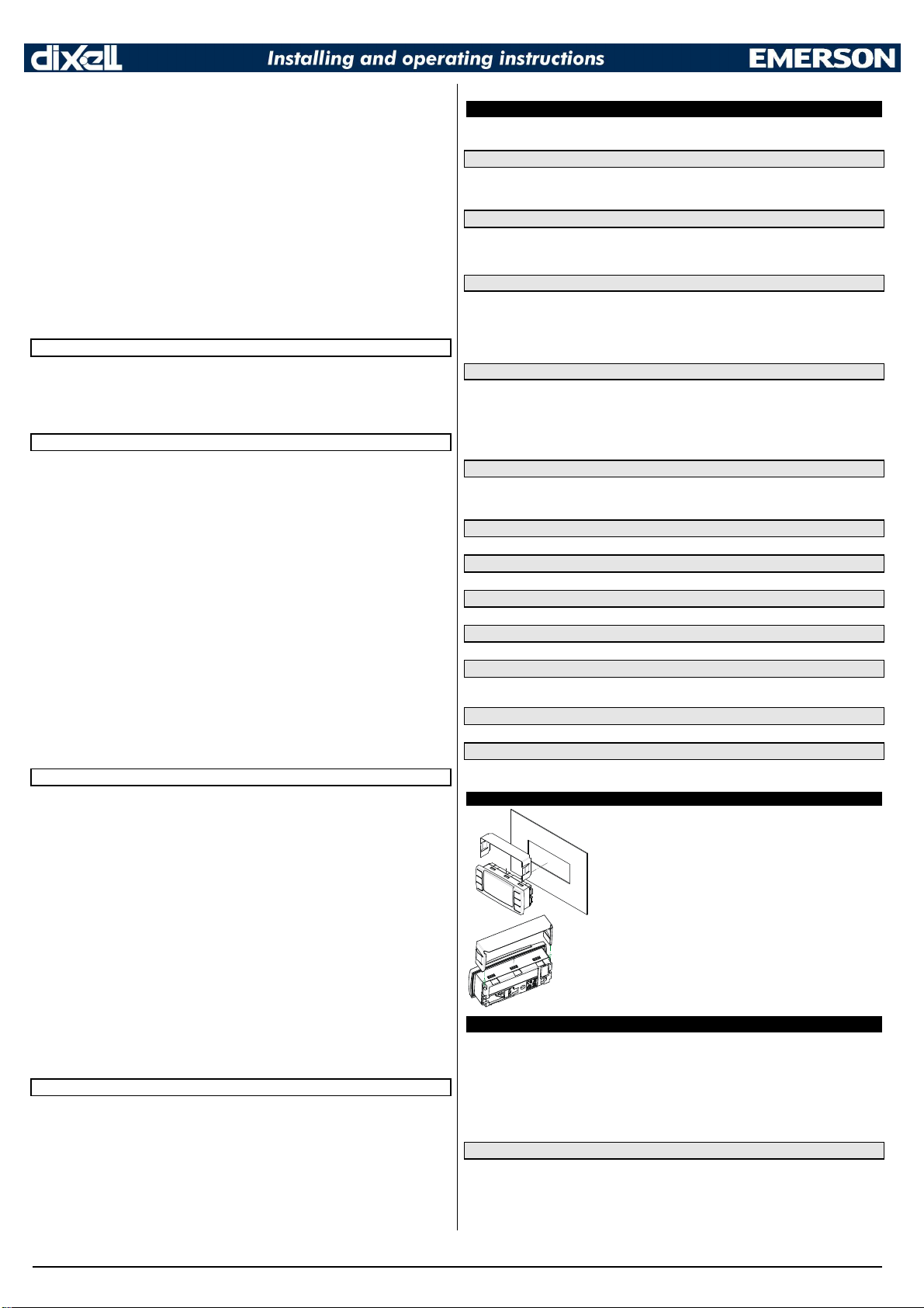
11. INSTALLATION AND MOUNTING
The CX660 keyboard shall be mounted on vertical panel, in a
29x71 mm hole, and fixed using the special bracket supplied. The
temperature range allowed for correct operation is 0÷60 °C. Avoid
places subject to strong vibrations, corrosive gases, excessive dirt
or humidity. The same recommendations apply to probes. Let air
circulate by the cooling holes.
12. ELECTRICAL CONNECTIONS
XM660K/XM669K is provided with screw terminal block to connect cables with a cross section up to 1,6
mm2 for all the low voltage connection: the RS485, the LAN, the probes, the digital inputs and the
keyboard. Other inputs, power supply and relays connections are provided with Faston connection (5.0
mm). Heat-resistant cables have to be used. Before connecting cables make sure the power supply
complies with the instrument’s requirements. Separate the probe cables from the power supply cables,
from the outputs and the power connections. Do not exceed the maximum current allowed on each
relay, in case of heavier loads use a suitable external relay. N.B. Maximum current allowed for all the
loads is 16A.
12.1 PROBE CONNECTIONS
The probes shall be mounted with the bulb upwards to prevent damages due to casual liquid infiltration.
It is recommended to place the thermostat probe away from air streams to correctly measure the
average room temperature. Place the defrost termination probe among the evaporator fins in the coldest
place, where most ice is formed, far from heaters or from the warmest place during defrost, to prevent
premature defrost termination.
1592023020 XM660K_XM669K GB r1.0 07.01.2013.doc XM660K - XM669K 5/8
Page 6

Message
Cause Outputs
“PON” Keyboard enabled
Outputs unchanged
“POF” Keyboard locked
Outputs unchanged
“rst” Alarm reset
Alarm relay reset
“nOP” probe not present
Compressor output acc. to par.
“
Con
” and “
COF”
“P1” First probe failure
Compressor output acc. to par.
“
Con
” and “
COF”
“P2” Second probe failure
Defrost end is timed
“P3” Third probe failure
Outputs unchanged
“P4” Fourth probe failure
Outputs unchanged
“P5” Fifth probe failure
Outputs unchanged
“P6”
Sixth probe failure
Outputs unchanged
“HA” Maximum temperature alarm
Outputs unchanged.
“LA” Minimum temperature alarm
Outputs unchanged.
"HAd Defrost high temperature
Outputs unchanged.
"LAd” Defrost low temperature
Outputs unchanged.
"FAd” Defros
t low temperature
Outputs unchanged.
"HAF” Fan high temperature
Outputs unchanged.
"LAF” Fan high temperature
Outputs unchanged.
"StP” Stop due to regulation pauses
(Sti and
Compressor and valve OFF
“PAL” Lock due to pressure switch
All outputs OFF.
“rtc” RTC wrongly configured
Outputs unchanged
“rtf” RTC failure
Outputs unchanged
“dA” Door open
Compressor and fans restarts according to rrd and
“EA” External alarm
Output unchanged.
“CA” Serious external alarm (i#
F=bAL) All outpu
ts OFF.
“EE” EEPROM failure
All outputs OFF.
“LOP” Minimum operating pressure reached
according to dML
“MOP” Maximum operating pressure reached
according to dML
“LSH” Minimum superheat alarm
Valve closed
“MSH” Maximum superheat alarm
outputs unchange
d
13. RS485 SERIAL LINE
XM660K/XM669K is provided of a direct RS485 connection that allow the unit, to be linked to a network
line ModBUS-RTU compatible with all dIXEL m onitoring system.
14. USE OF THE PROGRAMMING “HOT KEY“
The XM units can UPLOAD or DOWNLOAD the parameter list from its own E2 internal memory to the
“Hot Key” and vice-versa through a TTL connector.
14.1 DOWNLOAD (FROM THE “HOT KEY” TO THE INSTRUMENT)
1. Turn OFF the instrument by means of the ON/OFF key ,insert the “Hot Key” and then turn the
unit ON.
2. Automatically the parameter list of the “Hot Key” is downloaded into the controller memory, the
“doL” message is blinking. After 10 seconds the instrument will restart working with the new
parameters. At the end of the data transfer phase the instrument displays the following
messages: “end“ for right programming. The instrument starts regularly with the new
programming. “err” for failed programming. In this case turn the unit off and then on if you want
to restart the download again or remove the “Hot key” to abort the operation.
14.2 UPLOAD (FROM THE INSTRUMENT TO THE “HOT KEY”)
1. When the XM unit is ON, insert the “Hot key” and push è key; the "uPL" message appears.
2. The UPLOAD begins; the “uPL” message is blinking.
3. Remove the “Hot Key”.
At the end of the data transfer phase the instrument displays the following messages:
“end “ for right programming.
“err” for failed programming. In this case push “SET” key if you want to restart the programming
again or remove the not programmed “Hot key”.
15. ALARM SIGNALS
Power supply: depending on the model 12Vac – 24Vac - 110Vac
±
10% - 230Vac ± 10% or
90÷230Vac with switching power supply.
Power absorption: 9VA max.
Inputs: up to 6 NTC/PTC/Pt1000 probes
Digital inputs: 2 free of voltage
Relay outputs: Total current on loads M AX. 16A
Solenoid Valve: relay SPST 8 A, 250Vac
defrost: relay SPST 16 A, 250Vac
fan: relay SPST 8 A, 250Vac
light: relay SPST 16 A, 250Vac
Valve output: a.c. output up to 30W (Only XM669K)
Optional output (AnOUT) DEPENDING ON THE MODELS:
• PWM / Open Collector outputs: PWM or 12Vdc max 40mA
• Analog output: 4÷20mA or 0÷10V
Serial output: RS485 with ModBUS - RTU and LAN
Data storing: on the non-volatile memory (EEPROM).
Kind of action: 1B. Pollution grade: normal Software class: A. Operating temperature: 0÷60 °C.
Storage temperature: -25÷60 °C. Relative humidity: 20÷85% (no condensing).
Measuring and regulation range:
NTC probe: -40÷110°C (-58÷230°F).
PTC probe: -50÷150°C (-67 ÷ 302°F)
Pt1000 probe: -100 ÷ 100°C (-148 ÷ 212°F)
Resolution: 0,1 °C or 1°C or 1 °F (selectable). Accuracy (ambient temp. 25°C): ±0,5 °C ±1 digit
17. CONNECTIONS
17.1 XM660K – ALL POWER SUPPLY
Std parameters)
odc
15.1 “EE” ALARM
The dIXEL instruments are provided with an internal check for the data integrity. Alarm “EE” flashes
when a failure in the memory data occurs. In such cases the alarm output is enabled.
15.2 ALARM RECOVERY
Probe alarms : “P1” (probe1 faulty), “P2”, “P3”, “P4”, “P5”, “P6”; they automatically stop 10s after the
probe restarts normal operation. Check connections before replacing the probe. Temperature alarms
“HA”, “LA”, “HAd”, “LAd”, “HAF”, “LAF” automatically stop as soon as the thermostat temperature
returns to normal values or when the defrost starts. External alarms “EAL”, “BAL” stop as soon as the
external digital input is disabled.
16. TECHNICAL DATA
CX660 keyboard
Housing: self extinguishing ABS.
Case: CX660 facia 35x77 mm; depth 18mm
Mounting: panel mounting in a 29x71 mm panel cut-out
Protection: IP20; Frontal protection: IP65
Power supply: from XM600K power module
Display: 3 digits, red LED, 14,2 mm high;
Optional output: buzzer
Power modules
Case: 8 DIN
Connections: Screw terminal block ≤ 1,6 mm2 heat-resistant wiring and 5.0mm Faston
17.2 XM669K – 230/110VAC VALVE COIL
NOTE: the jumper indicated as JMP is inside the case of the controller. This jumper
has to be closed only in case of driving 24Vac valve.
17.3 XM669K – 24VAC VALVE COIL
18. DEFAULT SETTING VALUES
Lab Val Menù Description Range
SEt
2.0 - - - Set point LS - US
Regulation
Hy
2.0 Pr1 Differential [0.1°C ÷ 25.5°C] [1°F ÷ 45°F]
Int
150 Pr1
CrE
n Pr1
LS
-30 Pr2 Minimum set point [-55.0°C ÷ SET] [-67°F ÷ SET]
US
20 Pr2 Maximum set point
odS
0 Pr1
AC
0 Pr1 Anti-short cycle delay 0 ÷ 60 (min.)
CCt
0.0 Pr2 Continous cycle duration 0 ÷ 24.0(144) (hour.10min)
Integral time for room
temperature regulation
Continuous regulation
activation
Outputs activation delay at start
up
0 ÷ 255 s
n(0) – Y(1)
[SET ÷ 150.0°C] [SET ÷
302°F]
0 ÷ 255 (min.)
1592023020 XM660K_XM669K GB r1.0 07.01.2013.doc XM660K - XM669K 6/8
Page 7
1.0 ÷ P20
[PRM=Abs] 0.0 ÷ P20
14 ÷ P20
[PRM=Abs] 0 ÷ P20
10 ÷ P20
BAR : [PrM=rEL] PA4 ÷ 50.0
[PrM=AbS] PA4 ÷ 50.0
PSI : [PrM=rEL] PA4 ÷ 725
[PrM=AbS] PA4 ÷ 725
dKP : [PrM=rEL] PA4 ÷ 500
(Only for model with RTC)
CCS
2.0 Pr2 Continuous cycle set point
Con
15 Pr2
CoF
30 Pr2
CF
°C
PrU
rE Pr2 Pressure Mode rE(0) - Ab(1)
PMU
bAr Pr2 Pressure measurement unit bAr(0) – PSI(1) - MPA(2)
PMd
PrE Pr2
rES
dE Pr2
Lod
P1 Pr2 Local display: default display
rEd
P1 Pr2 Remote display: default display
dLy
0 Pr1 Display delay 0 ÷ 24.0(144) (Min.10s)
rPA
P1 Pr1 Regulation probe A
rPb
nP Pr1 Regulation probe B
rPE
100 Pr1
Electronic Expansion Valve
Fty
404 Pr1 Kind of gas
SSH
8.0 Pr1 Superheat set point [0.1°C ÷ 25.5°C] [1°F ÷ 45°F]
CyP
6 Pr1 Cycle Period 1 ÷ 15 s
Pb
5.0 Pr1
rS
0.0 Pr1
inC
120 Pr1
PEO
50 Pr1 Probe error opening percentage 0 ÷ 100
PEd
On Pr1
OPE
85 Pr1 Start opening percentage 0 ÷ 100
SFd
1.3 Pr1 Start function duration 0 ÷ 42.0(252) (min.10sec)
OPd
100 Pr1
Pdd
1.3 Pr1 Post defrost function duration 0 ÷ 42.0(252) (min.10sec)
MnF
100
dCL
0 Pr1
Fot
nu Pr1 Forced opening percentage 0 ÷ 100 - "nu"(101)
tPP
PP Pr2 Type of pressure transducer PP(0) - LAN(1)
PA4
-0.5 Pr2 Probe value at 4 mA or at 0V
P20
11.0 Pr2 Probe value at 20 mA or at 5V
LPL
-0.5 Pr1
MOP
11.0 Pr1
LOP
-0.5 Pr1
dML
30 Pr1
MSH
80.0 Pr1
LSH
1.0 Pr1
SHy
0.5 Pr1 Superheat alarm hysteresis [0.1°C ÷ 25.5°C] [1°F ÷ 45°F]
SHd
3.0 Pr1
FrC
100 Pr1 Fast-recovery costant 0 ÷ 100
Defrost
dPA
P2 Pr1 Defrost probe A
Compressor ON time with faulty
probe
Compressor OFF time with
faulty probe
Measurement unit: Celsius ,
Pr2
Fahrenheit
Pressure displaying mode:
temperature or pressure
Resolution (only °C) : decimal,
integer
Virtual probe percentage (room
temperature)
Proportional band for superheat
regulator
Band Offset for superheat
regulator
Integration time for superheat
regulator
Probe error delay before
stopping regulation
Opening percentage after
defrost phase
Maximum opening percentage
Pr1
at normale functioning
Delay before stopping valve
regulation
Lower pressure limit for
superheat regulation
Maximum operating pressure
threshold
Lowest operating pressure
threshold
Delta MOP-LOP opening
variation
Maximum superheat alarm
threshold
Minimum superheat alarm
threshold
Superheat alarm activation
delay
[-55.0°C ÷ 150,0°C] [-67°F ÷
0 ÷ 255 (min.)
0 ÷ 255 (min.)
tEM(0) - PrE(1)
nP(0) - P1(1) - P2(2) - P3(3) -
P4(4) - P5(5) - P6(6) – tEr(7) -
nP(0) - P1(1) - P2(2) - P3(3) -
P4(4) - P5(5) - P6(6) – tEr(7) -
nP(0) - P1(1) - P2(2) - P3(3) -
P4(4) - P5(5)
nP(0) - P1(1) - P2(2) - P3(3) -
P4(4) - P5(5)
0 ÷ 100 (100=rPA, 0=rPb)
R22(0) - 134(1) - 404(2) 407(3) - 410(4) - 507(5) -
[0.1°C ÷ 60.0 °C] [1°F ÷ 108
[-12.0°C ÷ 12.0°C] [-12°C ÷
12°C] [-21°F ÷ 21°F]
0 ÷ 239 s - On(240)
BAR : [PrM=rEL] -
PSI : [PrM=rEL] dKP : [PrM=rEL] -
[PRM=Abs] 0 ÷ P20
[PrM=AbS] PA4 ÷ 500
[LSH ÷ 80,0°C] [LSH ÷
[0.0 ÷ MSH °C] [0 ÷ MSH
0 ÷ 42.0(252) (min.10sec)
nP(0) - P1(1) - P2(2) - P3(3) -
P4(4) - P5(5)
302°F]
°C(0) - °F(1)
dE(0) - in(1)
dEF(8)
dEF(8)
CO2(6)
°F]
0 ÷ 255 s
0 ÷ 100
0 ÷ 100
0 ÷ 255 s
PA4 ÷ P20
LOP ÷ P20
PA4 ÷ MOP
0 ÷ 100
144°F]
°F]
dPb
nP Pr1 Defrost probe B
dPE
100 Pr1
tdF
EL Pr1 Defrost type EL(0) - in(0)
EdF
in Pr1
Srt
150 Pr1 Heater set point during defrost
Hyr
2.0 Pr1 Differential for heater [0.1°C ÷ 25.5°C] [1°F ÷ 45°F]
tod
255 Pr1 Time out for heater 0 ÷ 255 (min.)
dtP
0.1 Pr1
ddP
60 Pr1 Delay before starting defrost 0 ÷ 60 (min.)
d2P
n Pr1 Defrost with two probes n(0) – Y(1)
dtE
8.0 Pr1
dtS
8.0 Pr1
idF
6 Pr1 Interval between defrosts 0 ÷ 120 (hours)
MdF
30
dSd
0 Pr1 Start defrost delay 0 ÷ 255 (min.)
dFd
it Pr1 Display during defrost rt(0) - it(1) - SEt(2) - dEF(3)
dAd
30
Fdt
0 Pr1 Drain down time 0 ÷ 255 (min.)
dPo
n Pr1 Defrost at start-up n(0) – Y(1)
dAF
0.0
Fan
FPA
P2 Pr1 Fan probe A
FPb
nP Pr1 Fan probe B
FPE
100 Pr1
FnC
O-n Pr1 Fan operating mode
Fnd
10 Pr1 Fan delay after defrost 0 ÷ 255 (min.)
FCt
10 Pr1
FSt
2.0 Pr1 Fan stop temperature
FHy
1.0 Pr1 Fan stop differential [0.1°C ÷ 25.5°C] [1°F ÷ 45°F]
Fod
0 Pr1
Fon
0
FoF
0 Pr1 Fan OFF time 0÷15 (min.)
trA
UAL Pr2
SOA
80 Pr2 Fixed speed for fan AMi ÷ AMA
SdP
30.0 Pr2 Default Dew Point value
ASr
1.0 Pr2
PbA
5.0 Pr2
AMi
0
AMA
100 Pr2
AMt
200 Pr2
Alarm
rAL
P1 Pr1 Probe for temperature alarm
ALC
Ab Pr1
ALU
10 Pr1 High temperature alarm setting
ALL
-30 Pr1 Low temperature alarm setting
AHy
1.0 Pr1
ALd
15 Pr1 Temperature alarm delay 0 ÷ 255 (min.)
dLU
150 Pr2
dLL
-55 Pr2
Virtual probe percentage
(defrost temperature)
Defrost mode: Clock or interval
Minimum temperature
difference to start defrost
Defrost termination temperature
(Probe A)
Defrost termination temperature
(Probe B)
Defrost Maximum duration 0 ÷ 255 (min.)
Pr1
Defrost display time out 0 ÷ 255 (min.)
Pr1
Defrost delay after continuous
Pr1
cycle
Virtual probe percentage (fan
management)
Temperature differential to
avoid short cycles of fans
Fan activation time after defrost
(without compressor)
Fan ON time 0÷15 (min.)
Pr1
Kind of regulation for
modulating output
Differential for fan / offset for
anti sweat heater
Proportional band for
modulating output
Minimum output for modulating
Pr2
output
Maximum output for modulating
output
Time with fan at maximum
speed
Temperature alarm
configuration
Differential for temperature
alarm
High temperature alarm setting
(defrost probe)
Low temperature alarm setting
(defrost probe)
nP(0) - P1(1) - P2(2) - P3(3) -
P4(4) - P5(5)
0 ÷ 100 (100=dPA, 0=dPb)
[-55.0°C ÷ 150°C] [-67°F ÷
[0.1°C ÷ 50.0°C] [1°F ÷
[-55.0°C ÷ 50.0°C] [-67°F ÷
[-55.0°C ÷ 50.0°C] [-67°F ÷
0 ÷ 24.0(144) (hours.10min)
nP(0) - P1(1) - P2(2) - P3(3) -
P4(4) - P5(5)
nP(0) - P1(1) - P2(2) - P3(3) -
P4(4) - P5(5)
0 ÷ 100 (100=FPA, 0=FPb)
C-n(0) - O-n(1) - C-y(2) - O-
[0.0°C ÷ 50.0°C] [0°F ÷ 90°F]
[-55.0°C ÷ 50.0°C] [-67°F ÷
0 ÷ 255 (min.)
UAL(0) - rEG(1) - AC(2)
[-55.0°C ÷ 50.0°C] [-67°F ÷
[-25.5°C ÷ 25.5°C] [-45°F ÷
[0.1°C ÷ 25.5°C] [1°F ÷ 45°F]
nP(0) - P1(1) - P2(2) - P3(3) -
P4(4) - P5(5) - tEr(6)
rE(0) - Ab(1)
[0.0°C ÷ 50.0°C o ALL ÷
150.0°] [0°F ÷ 90°F o ALL ÷
[0.0°C ÷ 50.0°C o -55,0°C ÷
ALU] [0°F ÷ 90°F o -67°F
[0.1°C ÷ 25.5°C] [1°F ÷ 45°F]
dLL ÷ 150.0° or dLL ÷ 302°F
-55,0°C ÷ dLU or -67°F ÷ dLU
rtc(0) - in(1)
302°F]
90°F]
122°F]
122°F]
y(3)
122°F]
122°F]
45°F]
0 ÷ AMA
AMi ÷ 100
0 ÷ 255 s
302°F]
÷ ALU°F]
1592023020 XM660K_XM669K GB r1.0 07.01.2013.doc XM660K - XM669K 7/8
Page 8

Dig
ital
dAH
1.0 Pr2
ddA
15 Pr2
FLU
150 Pr2
FLL
-55
FAH
1.0 Pr2
FAd
15 Pr2
dAo
1.3 Pr1
EdA
30
dot
15 Pr1
Sti
1.3 Pr2 Stop regulation interval
Std
3 Pr2 Stop duration 1 ÷ 255 min
oA7
ALr Pr2
CoM
Cur
i1P
cL Pr1 Digital input 1 polarity OP(0) - CL(1)
i1F
dor Pr1 Digital input 1 configuration
d1d
15 Pr1 Digital input 1 activation delay 0 ÷ 255 (min.)
i2P
cL Pr1 Digital input 2 polarity OP(0) - CL(1)
i2F
LiG Pr1 Digital input 2 configuration
d2d
5 Pr1 Digital input 2 activation delay 0 ÷ 255 (min.)
nPS
15 Pr1
OdC
F-C Pr1
rrd
30 Pr1
Clock
CbP
Y Pr1 Clock presence n(0) – Y(1)
Hur
- - - Pr1 Current hour - - -
Min
- - -
dAY
- - - Pr1 Current day Sun(0) - SAt(6)
Hd1
nu Pr1 First weekly day Sun(0) - SAt(6) - nu(7)
Hd2
nu
Hd3
nu Pr1 Third weekly day Sun(0) - SAt(6) - nu(7)
ILE
0.0 Pr1
dLE
0.0 Pr1
ISE
0.0 Pr1
dSE
0.0 Pr1
HES
0.0 Pr1
Ld1
nu Pr1 Workdays First defrost start
Ld2
nu Pr1 Workdays Second defrost start
Ld3
nu Pr1 Workdays Third defrost start
Ld4
nu Pr1 Workdays Fourth defrost start
Ld5
nu Pr1 Workdays Fifth defrost start
Ld6
nu Pr1 Workdays Sixth defrost start
Sd1
nu Pr1 Holidays First defrost start
Sd2
nu Pr1 Holidays Second defrost start
Sd3
nu Pr1 Holidays Third defrost start
Sd4
nu Pr1 Holidays Fourth defrost start
Sd5
nu Pr1 Holidays Fifth defrost start
Differential for temperature
alarm (defrost probe)
Temperature alarm delay
(defrost probe)
High temperature alarm setting
(fan probe)
Low temperature alarm setting
Pr2
(fan probe)
Differential for temperature
alarm (fan probe)
Temperature alarm delay (fan
probe)
Delay of temperature alarm at
start-up
Alarm delay at the end of
Pr1
defrost
Temperature alarm exclusion
after door open
Modulating output configuration
(if CoM=oA7)
Modulating output configuration
Pr2
Inputs
Number of pressure switch
activation before lock
Compressor and fan status
when open door
Outputs restart after door open
alarm
Current minutes - - -
Pr1
Second weekly day Sun(0) - SAt(6) - nu(7)
Pr1
Energy saving cycle start during
workdays
Energy saving cycle length
during workdays
Energy saving cycle start during
holidays
Energy saving cycle length
during holidays
Temperature increasing during
Energy Saving cycle
[0.1°C ÷ 25.5°C] [1°F ÷ 45°F]
FLL ÷ 150.0° or FLL ÷ 302°F
-55,0°C ÷ FLU or -67°F ÷ FLU
[0.1°C ÷ 25.5°C] [1°F ÷ 45°F]
0 ÷ 24.0(144) (hours.10min)
CPr(0) - dEF(1) - FAn(2) -
ALr(3) - LiG(4) - AUS(5) -
CUr(0) - tEn(1) - PM5(2) -
EAL(0) - bAL(1) - PAL(2) -
dor(3) - dEF(4) - AUS(5) -
LiG(6) - OnF(7) - Htr(8) -
FHU(9) - ES(10) - Hdy(11)
EAL(0) - bAL(1) - PAL(2) -
dor(3) - dEF(4) - AUS(5) -
LiG(6) - OnF(7) - Htr(8) -
FHU(9) - ES(10) - Hdy(11)
no(0) - FAn(1) - CPr(2) - F-
0 - 23.5(143) (hours.10min)
0 ÷ 24.0(144) (hours.10min)
0 - 23.5(143) (hours.10min)
0 ÷ 24.0(144) (hours.10min)
[-30.0°C ÷ 30.0°C] [-54°F ÷
0.0 ÷ 23.5(143) - nu(144)
Ld1 ÷ 23.5(143) - nu(144)
Ld2 ÷ 23.5(143) - nu(144)
Ld3 ÷ 23.5(143) - nu(144)
Ld4 ÷ 23.5(143) - nu(144)
Ld5 ÷ 23.5(143) - nu(144)
0.0 ÷ 23.5(143) - nu(144)
Sd1 ÷ 23.5(143) - nu(144)
Sd2 ÷ 23.5(143) - nu(144)
Sd3 ÷ 23.5(143) - nu(144)
Sd4 ÷ 23.5(143) - nu(144)
"nu"(0) ÷ 24.0(144)
0 ÷ 255 (min.)
0 ÷ 255 (min.)
0 ÷ 255 min
0 ÷ 255 min
(hour.10min)
db(6) - OnF(7)
PM6(3) - oA7(4)
0 ÷ 15
C(3)
0 ÷ 255 (min.)
54°F]
(hours.10min)
(hours.10min)
(hours.10min)
(hours.10min)
(hours.10min)
(hours.10min)
(hours.10min)
(hours.10min)
(hours.10min)
(hours.10min)
(hours.10min)
Sd6
nu Pr1 Holidays Sixth defrost start
Energy Saving
ESP
P1 Pr1 Energy saving probe selection
HES
0.0 Pr1
PEL
n Pr1
L.A.N. Management
LMd
y Pr2 Defrost Synchronisation n(0) – Y(1)
dEM
y Pr2 Defrost end Synchronisation n(0) – Y(1)
LSP
n Pr2 SET-POINT Synchronisation n(0) – Y(1)
LdS
n Pr2
LOF
n Pr2 ON/OFF Synchronisation n(0) – Y(1)
LLi
y Pr2 Light Synchronisation n(0) – Y(1)
LES
n Pr2 Energy Saving Synchronisation n(0) – Y(1)
LSd
n Pr2 Remote probe displaying n(0) – Y(1)
LPP
n Pr2 Pressure value sent in LAN n(0) – Y(1)
StM
n Pr2
Probe Configurations
P1C
NtC Pr2 P1 configuration nP(0) - Ptc(1) - ntc(2) - PtM(3)
ot
0.0 Pr2 P1 calibration
P2C
NtC
oE
0.0 Pr2 P2 calibration
P3C
NtC Pr2 P3 configuration nP(0) - Ptc(1) - ntc(2) - PtM(3)
o3
0.0 Pr2 P3 calibration
P4C
NtC Pr2 P4 configuration nP(0) - Ptc(1) - ntc(2) - PtM(3)
o4
0.0 Pr2 P4 calibration
P5C
420 Pr2 P5 configuration
o5
0.0
P6C
PtM Pr2 P6 configuration nP(0) - Ptc(1) - ntc(2) - PtM(3)
o6
0.0 Pr2 P6 calibration
Service
CLt
- - - Pr1 ON/OFF percentage (C.R.O.) (read only)
tMd
- - - Pr1
LSn
- - - Pr1 Number of devices in LAN 1 ÷ 8 (read only)
LAn
- - - Pr1 List of address of LAN devices 1 ÷ 247 (read only)
Other
Adr
1
rEL
- - - Pr1 Firmware release (read only)
Ptb
- - - Pr1 Parameter table (read only)
Pr2
- - -
Temperature increasing during
Energy Saving
Energy saving activation when
Light switched off
Display Synchronisation
(temperature sent via LAN)
Cooling request from LAN
enable compressor relay
P2 configuration nP(0) - Ptc(1) - ntc(2) - PtM(3)
Pr2
P5 calibration
Pr2
Time remaining before next
defrost activation (only for
interval defrost)
Modbus address 1 ÷ 247
Pr1
PR2 menu access (read only)
Pr1
Sd5 ÷ 23.5(143) - nu(144)
(hours.10min)
nP(0) - P1(1) - P2(2) - P3(3) -
P4(4) - P5(5) - tEr(6)
[-30.0°C ÷ 30.0°C] [-54°F ÷
n(0) – Y(1)
n(0) – Y(1)
n(0) – Y(1)
[-12,0°C ÷ 12,0°C] [-21°F ÷
[-12,0°C ÷ 12,0°C] [-21°F ÷
[-12,0°C ÷ 12,0°C] [-21°F ÷
[-12,0°C ÷ 12,0°C] [-21°F ÷
nP(0) - Ptc(1) - ntc(2) - PtM(3)
- 420(4) - 5Vr(5)
[-12,0°C ÷ 12,0°C] [-21°F ÷
[-12,0°C ÷ 12,0°C] [-21°F ÷
(read only)
54°F]
21°F]
21°F]
21°F]
21°F]
21°F]
21°F]
1592023020 XM660K_XM669K GB r1.0 07.01.2013.doc XM660K - XM669K 8/8
 Loading...