

Page 1

100-412-196 - REV. 06
LPX
Power Supply
Instruction Manual
Branson Ultrasonics Corporation
41 Eagle Road
Danbury, CT 06813-1961 USA
(203) 796-0400
http://www.bransonultrasonics.com
Page 2

Manual Change Information
At Branson, we strive to maintain our position as the leader in ultrasonics plastics joining,
metal welding, cleaning and related technologies by continually improving our circuits and
components in our equipment. These improvements are incorporated as soon as they are
developed and thoroughly tested.
Information concerning any improvements will be added to the appropriate technical
documentation at its next revision and printing. Therefore, when requesting service
assistance for specific units, note the Revision information found on the cover of this
document, and refer to the printing date which appears at the bottom of this page.
Copyright and Trademark Notice
Copyright © 2014 Branson Ultrasonics Corporation. All rights reserved. Contents of this publication may not be
reproduced in any form without the written permission of Branson Ultrasonics Corporation.
Mylar is a registered trademark of DuPont Teijin Films.
Loctite is a registered trademark of Loctite Corporation, Newington, CT.
WD-40 is a registered trademark of WD-40 Manufacturing Company.
Windows 7, Windows Vista, and Windows XP are registered trademarks of Microsoft Corporation
Other trademarks and service marks mentioned herein are held by their respective
owners.
ii 100-412-196 REV. 06
Page 3

Foreword
Congratulations on your choice of a Branson Ultrasonics Corporation system!
The Branson LPX Power Supply system is process equipment for the joining of plastic parts
using ultrasonic energy. It is the newest generation of product using this sophisticated
technology for a variety of customer applications. This Instruction Manual is part of the
documentation set for this system, and should be kept with the equipment.
Thank you for choosing Branson!
Introduction
This manual is arranged into several structured chapters which will help you find the
information you may need to know to safely handle, install, set up, program, operate,
and/or maintain this product. Please refer to the Table Of Contents and/or the Index of
this manual to find the information you may be looking for. In the event you require
additional assistance or information, please contact our Product Support department (see
1.5 How to Contact Branson for information on how to contact them) or your local Branson
representative.
100-412-196 REV. 06 iii
Page 4

iv 100-412-196 REV. 06
Page 5

Table Of Contents
Chapter 1:Safety and Support
1.1 Safety Requirements and Warnings . . . . . . . . . . . . . . . . . . . . . . . . . . . . . . . . . . . 2
1.2 General Precautions. . . . . . . . . . . . . . . . . . . . . . . . . . . . . . . . . . . . . . . . . . . . . . 4
1.3 Regulatory Compliance. . . . . . . . . . . . . . . . . . . . . . . . . . . . . . . . . . . . . . . . . . . . 6
1.4 Warranty Statement, Disclaimer . . . . . . . . . . . . . . . . . . . . . . . . . . . . . . . . . . . . . 7
1.5 How to Contact Branson . . . . . . . . . . . . . . . . . . . . . . . . . . . . . . . . . . . . . . . . . . . 9
1.6 Returning Equipment for Repair . . . . . . . . . . . . . . . . . . . . . . . . . . . . . . . . . . . . .10
1.7 Obtaining Replacement Parts . . . . . . . . . . . . . . . . . . . . . . . . . . . . . . . . . . . . . . .13
Chapter 2:Introduction
2.1 Principle of Operation. . . . . . . . . . . . . . . . . . . . . . . . . . . . . . . . . . . . . . . . . . . . . 16
2.2 Front Panel Controls and Indicators . . . . . . . . . . . . . . . . . . . . . . . . . . . . . . . . . . .17
2.3 Back Panel Connections . . . . . . . . . . . . . . . . . . . . . . . . . . . . . . . . . . . . . . . . . . . 22
Chapter 3:Delivery and Handling
3.1 Delivery and Handling . . . . . . . . . . . . . . . . . . . . . . . . . . . . . . . . . . . . . . . . . . . . 24
Chapter 4:Technical Specifications
4.1 Technical Specifications . . . . . . . . . . . . . . . . . . . . . . . . . . . . . . . . . . . . . . . . . . . 26
4.2 System Performance Benchmark . . . . . . . . . . . . . . . . . . . . . . . . . . . . . . . . . . . . . 29
4.3 Branson Power Supply Setup Form . . . . . . . . . . . . . . . . . . . . . . . . . . . . . . . . . . . 30
Chapter 5:Installation and Setup
5.1 Installation Checklist . . . . . . . . . . . . . . . . . . . . . . . . . . . . . . . . . . . . . . . . . . . . . 32
5.2 System Component Description. . . . . . . . . . . . . . . . . . . . . . . . . . . . . . . . . . . . . . 33
5.3 Assembling the Equipment . . . . . . . . . . . . . . . . . . . . . . . . . . . . . . . . . . . . . . . . .38
5.4 Input Power Requirements . . . . . . . . . . . . . . . . . . . . . . . . . . . . . . . . . . . . . . . . .41
5.5 Electrical Connections to Equipment . . . . . . . . . . . . . . . . . . . . . . . . . . . . . . . . . .42
5.6 Guards and Safety Equipment. . . . . . . . . . . . . . . . . . . . . . . . . . . . . . . . . . . . . . .44
Chapter 6:Operation
6.1 Front Panel Controls . . . . . . . . . . . . . . . . . . . . . . . . . . . . . . . . . . . . . . . . . . . . .46
6.2 System Modes. . . . . . . . . . . . . . . . . . . . . . . . . . . . . . . . . . . . . . . . . . . . . . . . . .47
6.3 Main Screen Navigation . . . . . . . . . . . . . . . . . . . . . . . . . . . . . . . . . . . . . . . . . . .48
6.4 System Configuration Registers. . . . . . . . . . . . . . . . . . . . . . . . . . . . . . . . . . . . . . 50
6.5 Operational Sequence . . . . . . . . . . . . . . . . . . . . . . . . . . . . . . . . . . . . . . . . . . . .53
6.6 Save/Recall Weld Preset. . . . . . . . . . . . . . . . . . . . . . . . . . . . . . . . . . . . . . . . . . .64
Chapter 7:Maintenance
7.1 Maintenance and Troubleshooting . . . . . . . . . . . . . . . . . . . . . . . . . . . . . . . . . . . .68
7.2 Reconditioning the Stack Interface . . . . . . . . . . . . . . . . . . . . . . . . . . . . . . . . . . .70
7.3 Troubleshooting Charts . . . . . . . . . . . . . . . . . . . . . . . . . . . . . . . . . . . . . . . . . . .73
7.4 Alarms/Errors . . . . . . . . . . . . . . . . . . . . . . . . . . . . . . . . . . . . . . . . . . . . . . . . . .76
100-412-196 REV. 06 v
Page 6

vi 100-412-196 REV. 06
Page 7

List Of Figures
Chapter 1:Safety and Support
Figure 1.1 Safety Label found on the back of the LPX Power Supply.. . . . . . . . . . . . . . . . . . . . 3
Chapter 2:Introduction
Figure 2.1 LPX Power Supply . . . . . . . . . . . . . . . . . . . . . . . . . . . . . . . . . . . . . . . . . . . . . . . 16
Figure 2.2 Front-Panel Controls . . . . . . . . . . . . . . . . . . . . . . . . . . . . . . . . . . . . . . . . . . . . .17
Figure 2.3 Back Panel of LPX Power Supply . . . . . . . . . . . . . . . . . . . . . . . . . . . . . . . . . . . . .22
Chapter 3:Delivery and Handling
Chapter 4:Technical Specifications
Figure 4.1 Declaration of Conformity. . . . . . . . . . . . . . . . . . . . . . . . . . . . . . . . . . . . . . . . . .28
Chapter 5:Installation and Setup
Figure 5.1 Connecting Tip to Horn . . . . . . . . . . . . . . . . . . . . . . . . . . . . . . . . . . . . . . . . . . .40
Chapter 6:Operation
Figure 6.1 LPX Power Supply User Interface . . . . . . . . . . . . . . . . . . . . . . . . . . . . . . . . . . . .46
Chapter 7:Maintenance
Figure 7.1 Reconditioning Stack Mating Surface . . . . . . . . . . . . . . . . . . . . . . . . . . . . . . . . . .70
Figure 7.2 LPX Power Supply Interconnect Diagram . . . . . . . . . . . . . . . . . . . . . . . . . . . . . . . 75
100-412-196 REV. 06 vii
Page 8

viii 100-412-196 REV. 06
Page 9

List Of Tables
Chapter 1:Safety and Support
Table 1.1 Warranty Period . . . . . . . . . . . . . . . . . . . . . . . . . . . . . . . . . . . . . . . . . . . . . . . . 7
Table 1.2 Branson Contacts . . . . . . . . . . . . . . . . . . . . . . . . . . . . . . . . . . . . . . . . . . . . . . .12
Chapter 2:Introduction
Table 2.1 Front Panel Controls and Indicators . . . . . . . . . . . . . . . . . . . . . . . . . . . . . . . . . . .18
Table 2.2 LCD Icons. . . . . . . . . . . . . . . . . . . . . . . . . . . . . . . . . . . . . . . . . . . . . . . . . . . . .20
Table 2.3 Connections to the LPX Power Supply . . . . . . . . . . . . . . . . . . . . . . . . . . . . . . . . .22
Chapter 3:Delivery and Handling
Chapter 4:Technical Specifications
Table 4.1 Environmental Specifications . . . . . . . . . . . . . . . . . . . . . . . . . . . . . . . . . . . . . . .26
Table 4.2 Input Voltage . . . . . . . . . . . . . . . . . . . . . . . . . . . . . . . . . . . . . . . . . . . . . . . . . .26
Table 4.3 Current Rating Fusing . . . . . . . . . . . . . . . . . . . . . . . . . . . . . . . . . . . . . . . . . . . .26
Table 4.4 Maximum Power Limit . . . . . . . . . . . . . . . . . . . . . . . . . . . . . . . . . . . . . . . . . . . .27
Table 4.5 Dimensions and Weight . . . . . . . . . . . . . . . . . . . . . . . . . . . . . . . . . . . . . . . . . . .27
Table 4.6 System Performance Benchmark . . . . . . . . . . . . . . . . . . . . . . . . . . . . . . . . . . . . . 29
Chapter 5:Installation and Setup
Table 5.1 20 kHz LPX Power Supply Converter Compatibility. . . . . . . . . . . . . . . . . . . . . . . . . 33
Table 5.2 30 kHz LPX Power Supply Converter Compatibility. . . . . . . . . . . . . . . . . . . . . . . . . 34
Table 5.3 40 kHz LPX Power Supply Converter Compatibility. . . . . . . . . . . . . . . . . . . . . . . . . 34
Table 5.4 LPX Power Supply Converter Part Numbers. . . . . . . . . . . . . . . . . . . . . . . . . . . . . .35
Table 5.5 Start Cable Part Numbers . . . . . . . . . . . . . . . . . . . . . . . . . . . . . . . . . . . . . . . . . .35
Table 5.6 RF Cable Part Numbers . . . . . . . . . . . . . . . . . . . . . . . . . . . . . . . . . . . . . . . . . . .36
Table 5.7 Handheld Welder Part Numbers. . . . . . . . . . . . . . . . . . . . . . . . . . . . . . . . . . . . . . 36
Table 5.8 Maximum Power/Duty Cycle . . . . . . . . . . . . . . . . . . . . . . . . . . . . . . . . . . . . . . . .37
Table 5.9 Setup Procedure . . . . . . . . . . . . . . . . . . . . . . . . . . . . . . . . . . . . . . . . . . . . . . . . 38
Table 5.10 Connecting the horn to the converter. . . . . . . . . . . . . . . . . . . . . . . . . . . . . . . . . . 39
Table 5.11 Stud Torque Values, Torque Wrench Part Numbers . . . . . . . . . . . . . . . . . . . . . . . .39
Table 5.12 Connecting the tip to the horn . . . . . . . . . . . . . . . . . . . . . . . . . . . . . . . . . . . . . .40
Table 5.13 User I/O Pin-Out (DB9F) provided for customer-designed interface . . . . . . . . . . . . .43
Chapter 6:Operation
Table 6.1 System Modes and Description . . . . . . . . . . . . . . . . . . . . . . . . . . . . . . . . . . . . . . 47
Table 6.2 Modify Registers . . . . . . . . . . . . . . . . . . . . . . . . . . . . . . . . . . . . . . . . . . . . . . . .50
Table 6.3 Register Settings . . . . . . . . . . . . . . . . . . . . . . . . . . . . . . . . . . . . . . . . . . . . . . . .50
Table 6.4 Energy Mode Parameters . . . . . . . . . . . . . . . . . . . . . . . . . . . . . . . . . . . . . . . . . . 53
Table 6.5 Energy Mode Operational Sequence. . . . . . . . . . . . . . . . . . . . . . . . . . . . . . . . . . .53
Table 6.6 Time Mode Parameters. . . . . . . . . . . . . . . . . . . . . . . . . . . . . . . . . . . . . . . . . . . . 57
Table 6.7 Time Mode Operational Sequence . . . . . . . . . . . . . . . . . . . . . . . . . . . . . . . . . . . .57
Table 6.8 Continuous Mode Parameters . . . . . . . . . . . . . . . . . . . . . . . . . . . . . . . . . . . . . . .61
Table 6.9 Continuous Mode Operational Sequence . . . . . . . . . . . . . . . . . . . . . . . . . . . . . . . .61
Table 6.10 Saving a Weld Preset in Memory . . . . . . . . . . . . . . . . . . . . . . . . . . . . . . . . . . . . .64
Table 6.11 Recalling a Weld Preset from Memory . . . . . . . . . . . . . . . . . . . . . . . . . . . . . . . . .65
Chapter 7:Maintenance
Table 7.1 Torque Specifications . . . . . . . . . . . . . . . . . . . . . . . . . . . . . . . . . . . . . . . . . . . . . 72
100-412-196 REV. 06 ix
Page 10

Table 7.2 System Trouble Analysis Chart . . . . . . . . . . . . . . . . . . . . . . . . . . . . . . . . . . . . . . 73
Table 7.3 Alarms/Errors. . . . . . . . . . . . . . . . . . . . . . . . . . . . . . . . . . . . . . . . . . . . . . . . . . 76
x 100-412-196 REV. 06
Page 11

Chapter 1: Safety and Support
1.1 Safety Requirements and Warnings. . . . . . . . . . . . . . . . . . . . . . . . . . . 2
1.2 General Precautions . . . . . . . . . . . . . . . . . . . . . . . . . . . . . . . . . . . . . . . 4
1.3 Regulatory Compliance. . . . . . . . . . . . . . . . . . . . . . . . . . . . . . . . . . . . . 6
1.4 Warranty Statement, Disclaimer . . . . . . . . . . . . . . . . . . . . . . . . . . . . . 7
1.5 How to Contact Branson. . . . . . . . . . . . . . . . . . . . . . . . . . . . . . . . . . . . 9
1.6 Returning Equipment for Repair. . . . . . . . . . . . . . . . . . . . . . . . . . . . . 10
1.7 Obtaining Replacement Parts. . . . . . . . . . . . . . . . . . . . . . . . . . . . . . . 13
100-412-196 REV. 06 1
Page 12

1.1 Safety Requirements and Warnings
This chapter contains an explanation of the different Safety Notice symbols and icons
found both in this manual and on the product itself and provides additional safety
information for ultrasonic welding. This chapter also describes how to contact Branson for
assistance.
1.1.1 Symbols Found in this Manual
Three symbols used throughout this manual warrant special attention:
WARNING General Warning
Warning indicates a hazardous situation or practice which, if not
avoided, can result in serious injury or death.
CAUTION General Warning
Caution indicates a hazardous situation which, if not avoided, could
result in minor or moderate injury.
NOTICE
Notice is used to address practices not related to personal injury. It contains important
information. It might also alert the user to unsafe practices or conditions that can
damage equipment if not corrected.
2 100-412-196 REV. 06
Page 13
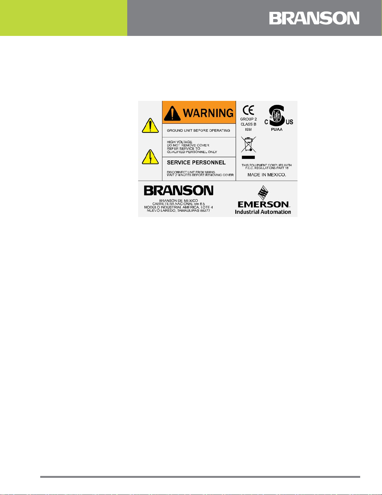
1.1.2 Symbols Found on the Product
The LPX Power Supply has several warning labels on it to alert the user of items of concern
or hazard.
The following warning symbols appear on the LPX Power Supply.
Figure 1.1 Safety Label found on the back of the LPX Power Supply.
100-412-196 REV. 06 3
Page 14

1.2 General Precautions
Observe the following safety considerations when operating the LPX Power Supply:
CAUTION General Warning
• Make sure that the equipment is properly grounded. DO NOT operate if it
is not.
• Units are equipped with a three-conductor cord, and must be plugged into
a three-prong grounding-type wall receptacle. DO NOT under any
circumstances remove the power cord ground prong.
• DO NOT operate the equipment with the cover removed. High voltage is
present within the equipment.
• DO NOT turn on ultrasonics without the converter and horn attached.
• DO NOT cycle the welding system if either the RF cable or converter is
disconnected.
• DO NOT touch the horn or tip when ultrasonics are active. When
handling, removing, or attaching a horn or tip, be sure that the ON/OFF
switch on the back of the unit is set to OFF. See
while the unit is on can result in serious personal injury (frictional burn).
• DO NOT position the equipment so that it is difficult to operate the ON/
OFF switch.
. Touching the horn or tip
1.2.1 Intended Use of the System
The LPX Power Supply can be used in conjunction with a Portable Hand Held Tool, as well
as ultrasonic stacks with standard and knurled horns and tips, spot welding tips, and
cutting blades to accomplish a wide variety of plastic and textile cutting and joining
processes.
1.2.2 Emissions
When being processed, certain plastic materials can emit toxic fumes, gases or other
emissions that can be hazardous to the operator’s health. Where such materials are
processed, proper ventilation of the workstation is required. Check your materials
suppliers for recommended protection when processing their materials.
WARNING Corrosive Material Hazard
Processing of many materials, such as PVC, can be hazardous to an
operator’s health and could cause corrosion/damage to the
equipment. Use proper ventilation and take protective measures.
4 100-412-196 REV. 06
Page 15

1.2.3 Safe Operation
Setup and Operation instructions are found in Chapter 6: Operation of this manual.
For safe operation, please ensure that all people using this equipment follow those
instructions and observe all CAUTION and WARNING notices.
Make sure that the equipment is properly grounded. DO NOT operate if it is not.
Periodically test the equipment as described in
CAUTION Loud Noise Hazard
On certain applications, sound level emissions over 80dB have can be
generated. To prevent the possibility of hearing loss, use appropriate
hearing protection.
NOTICE
Sound level and frequency of the noise emitted during the ultrasonic assembly process
may depend upon a. type of application, b. size, shape and composition of the material
being assembled, c. shape and material of the holding fixture, d. welder setup
parameters and e. tool design. Some parts vibrate at an audible frequency during the
process. Some or all of these factors may result in sound levels of over 80dB. In such
cases operators may need to be provided with personal protective equipment. See 29
CFR (Code of Federal Regulations) 1910.95 Occupational Noise Exposure. For all other
countries, follow your local regulations.
4.2 System Performance Benchmark.
CAUTION General Warning
Never touch the horn or tip when ultrasonics are active. Touching the
horn or tip while the unit is on can result in serious injury. When you
handle, remove, or attach a horn or tip, always make sure that the
ON/OFF switch on the back of the unit is set to OFF. See 2.3 Back Panel
Connections.
1.2.4 Setting Up the Workplace
Measures for setting up a workplace for safe operation of the ultrasonic welder are
outlined in Chapter 5: Installation and Setup.
100-412-196 REV. 06 5
Page 16

1.3 Regulatory Compliance
This product meets electrical safety requirements and EMC (Electromagnetic Compliance)
requirements for North America and the European Union.
All units comply with WEEE/RoHS requirements.
6 100-412-196 REV. 06
Page 17

1.4 Warranty Statement, Disclaimer
The following excerpts from the “Terms and Conditions of Sale” (found on the back of your
Invoice) are essential guidelines for the product Warranty issued with your Branson
ultrasonic welding components. The items listed in this section specifically address issues
involving the delivery, shipment, and warranty period provided. If you have any questions,
please refer to the back of the Invoice included with your system, which lists all of the
Terms and Conditions of Sale, or contact your Branson representative.
TERMS AND CONDITIONS OF SALE
Branson Ultrasonics Corporation is herein referred to as the “Seller” and the customer or
person or entity purchasing products (“Products”) from Seller is referred to as the “Buyer.”
Buyer’s acceptance of the Products will manifest Buyer’s assent to these Terms and
Conditions.
ULTRASONIC JOINING EQUIPMENT NORTH AMERICAN
WARRANTY POLICY
Each product manufactured by Branson is guaranteed to be free from defects in material
and workmanship for a period of time specified in Table 1.1 from the date of shipment.
Table 1.1 Warranty Period
Product Period
Power Supplies. 36 months.
Accessories. 36 months.
Converters.
Non-Branson equipment (i.e. printers,
etc.).
Horns.
Boosters. 36 months.
Handheld devices. 12 months.
Rental Equipment. Same as purchased equipment.
Specials and products with EDP prefix
159-xxx-xxx.
Specials and products with EDP prefix
125-xxx-xxx.
36 months (limited to one-time
replacement).
Warranted by the manufacturer.
12 months (limited to one-time
replacement).
12 months.
12 months.
100-412-196 REV. 06 7
Page 18

The warranty does not apply to:
• Any product which has been subject to misuse, misapplication, neglect (including without
limitation inadequate maintenance), accident or improper installation, modification or adjustment
• Applications requiring metal-to-metal contact when the ultrasonic exposure time exceeds 1.5
seconds
• Any product exposed to adverse environments, improper repair or repairs using non-Branson
methods or material
• Non-Branson equipment (i.e., horns, boosters, converters) or improperly tuned horns
• Set-up/installation of equipment and software updates
Warranty Service covers the following:
Repair service at Branson’s main repair facility or a regional office
• Includes parts and labor performed at Branson authorized repair facilities. The customer must
return the equipment properly packed with all shipping charges prepaid
Repair service at the customer site
• Includes parts and labor at the customer site performed by a Branson technician. The customer
is responsible for all travel-related charges
Module trade-in:
• Includes serialized components for work performed by the customer. The customer orders the
replacement components from the Parts Store and issues a P.O. When the failed components are
returned to Branson the warranty status is verified and a credit is issued. The customer is
responsible for all shipping charges
• Additional Warranty Notes
• Components replaced during in-warranty repair carry the remainder of the original warranty
• Serialized assemblies replaced during the repair of out-of-warranty equipment are warranted for
a period of 12 months
• Travel charges for Branson service personnel will be waived on service calls performed within 30
days of invoice date
• Non-serialized parts replaced during the repair of out-of-warranty equipment are warranted for 3
months.
• Trade in allowance: Branson out-of-warranty serialized components are entitled to a 25 % trade
in allowance regardless of age or condition, however, converters must be less than 5 years old to
qualify for the trade in
If you have any questions concerning the warranty coverage (including coverage outside
of North America), please contact your Branson representative or Branson Customer
Support.
8 100-412-196 REV. 06
Page 19

1.5 How to Contact Branson
Branson is here to help you. We appreciate your business and are interested in helping
you successfully use our products. To contact Branson for help, use the following
telephone numbers, or contact the field office nearest you (business hours from 8 a.m. to
4 p.m. Central and Eastern Time Zones):
• North American Headquarters (all Departments): (203) 796-0400
• Parts Store (direct number): (877) 330-0406
• Repair department: (877)-330-0405
• For emergency after-hours service (5 p.m. – 8 a.m. EST): (203) 796-0500 (US phone
numbers only).
Tell the operator which product you have and which person or department you need
(Table 1.2). If after hours, please leave a voice message with your name and return
telephone number.
1.5.1 Before Calling Branson for Assistance
This manual provides information for troubleshooting and resolving problems that could
occur with the equipment (see Chapter 7: Maintenance). If you still require assistance,
Branson Product Support is here to help you. To help identify the problem, use the
following questionnaire which lists the common questions you will be asked when you
contact the Product Support department.
Before calling, determine the following information:
1. Your company name and location.
2. Your return telephone number.
3. Have your manual with you. If troubleshooting a problem, refer to
4. Know your equipment model and serial numbers (found on a gray data label on the units).
Information about the horn (part number, gain, etc.) or other tooling may be etched into the
tooling. Software- or firmware-based systems may provide a BOS or software version number,
which may be required.
5. What tooling (horn) and booster are being used?
6. What are the setup parameters and mode?
7. Is your equipment in an automated system? If so, what is supplying the “start” signal?
8. Describe the problem; provide as much detail as possible. For example, is the problem
intermittent? How often does it occur? How long before it occurs if you are just powering up? If
an error is occurring, which error (give error number or name)?
9. List the steps you have already taken.
10.What is your application, including the materials being processed?
11.Have a list of service or spare parts you have on hand (tips, horns, etc.)
12.Notes:
____________________________________________________________________________
____________________________________________________________________________
____________________________________________________________________________
____________________________________________________________________________
________
Chapter 7: Maintenance.
100-412-196 REV. 06 9
Page 20

1.6 Returning Equipment for Repair
Before sending equipment for repair, provide as much information with the equipment to
help determine the problem with the system. Use the following page to record necessary
information.
NOTICE
To return equipment to Branson, you must first obtain an RGA number from a Branson
representative, or the shipment may be delayed or refused.
If you are returning equipment to Branson for repair, you must first call the Repair
department to obtain a Returned Goods Authorization (RGA) number. (If you request
it, the repair department will fax a Returned Goods Authorization form to fill out and
return with your equipment).
Branson Repair Department, C/O Zuniga Logistics, LTD
12013 Sara Road, Killam Industrial Park
Laredo, Texas 78045 U.S.A.
Direct telephone number: (877) 330-0405
Fax number: (877) 330-0404
• Provide as much information as possible that will help identify the need for repair.
• Carefully pack the equipment in original packing cartons.
• Clearly label all shipping cartons with the RGA number on the outside of cartons as well as on
your packing slip, along with the reason for return.
• Return general repairs by any convenient method. Send priority repairs by air freight.
• You must prepay the transportation charges FOB Laredo, Texas, U.S.A.
1.6.1 Get an RGA Number
RGA#
_______________________________________________________________________
If you are returning equipment to Branson, please call the Repair Department to obtain a
Returned Goods Authorization (RGA) number. (At your request, the Repair Department
will fax an RGA form to fill out and return with the equipment.)
10 100-412-196 REV. 06
Page 21

1.6.2 Record Information About the Problem
Before sending equipment for repair, record the following information and send a copy of it
with the equipment. This will greatly increase Branson’s ability to address the problem.
1. Describe the problem; provide as much detail as possible. For example, is the problem
intermittent? How often does it occur? How long before it occurs after powering up?
____________________________________________________________________________
____________________________________________________________________________
____________________________________________________________________________
____________________________________________________________________________
2. Is your equipment in an automated system?
____________________________________________________________________________
____________________________________________________________________________
3. If the problem is with an external signal, which signal?
____________________________________________________________________________
____________________________________________________________________________
4. If known, include plug/pin # (e.g., P29, pin #3) for that signal:
____________________________________________________________________________
____________________________________________________________________________
5. What are the Weld Parameters?
____________________________________________________________________________
____________________________________________________________________________
____________________________________________________________________________
____________________________________________________________________________
6. What is your application? (Type of weld, plastic material, etc.):
____________________________________________________________________________
____________________________________________________________________________
____________________________________________________________________________
7. Name and phone number of the person most familiar with the problem:
____________________________________________________________________________
____________________________________________________________________________
____________________________________________________________________________
Contact the Branson office prior to shipping the equipment.
For equipment not covered by warranty, to avoid delay, include a Purchase Order.
Send a copy of this page with the equipment being returned for repair.
100-412-196 REV. 06 11
Page 22

1.6.3 Departments to Contact
Call your local Branson Representative, or contact Branson by calling and asking for the
appropriate department, as indicated in Table 1.2 below.
Table 1.2 Branson Contacts
What you need help with or
information about
Information about new welding
systems or components.
Application and setup questions on
the welding system.
Application assistance on the horns
and tooling.
Technical questions about the
welding system.
Technical questions about horns
and tooling.
Ordering new parts. Parts Store. 877-330-0406
RGA’s, request for repair, status of
a repair.
System automation/hookup
information.
Your local Branson Rep or
Branson Customer Service.
Welding Applications Lab.
ATG Lab.
Welding Product Support.
ATG Lab.
Welding Repair
Department.
Product Support.
Whom to Call
At this Phone
Number...
203-796-0400
Ext 384
203-796-0400
Ext 368
203-796-0400
Ext 495
203-796-0400
Ext 355, 551
203-796-0400
Ext 495
877-330-0405
203-796-0400
Ext 355, 551
My Local Branson Representative’s name is:
_______________________________________________________________________
_______________________________________________________________________
I can reach this representative at:
_______________________________________________________________________
_______________________________________________________________________
1.6.4 Pack and Ship the Equipment
1. Carefully pack the system in original packing material to avoid shipping damage. Plainly show the
RGA number on the outside of cartons as well as inside the carton along with the reason for
return. Make a list of all components packed in the box. KEEP YOUR MANUAL
2. Return general repairs by any convenient method. Send priority repairs by air freight. Prepay the
transportation charges FOB the repair site
NOTICE
Items that are sent Freight Collect will be refused.
12 100-412-196 REV. 06
Page 23

1.7 Obtaining Replacement Parts
You can reach Branson Parts Store at the following telephone numbers:
Branson Part Store
Direct telephone number: 877-330-0406
Fax number: 877-330-0404
Many parts can be shipped the same day if ordered before 2:30 p.m., Eastern time.
A parts list is found in Chapter 7: Maintenance of this manual, listing descriptions and EDP
part numbers. If you need replacement parts, coordinate the following with your
purchasing agent:
• Purchase order number
• Ship to information
• Bill to information
• Shipping instructions (air freight, truck, etc.)
• Any special instructions (for example, “Hold at the airport and call”). Be sure to give a name and
phone number
• Contact name information
100-412-196 REV. 06 13
Page 24

14 100-412-196 REV. 06
Page 25

Chapter 2: Introduction
2.1 Principle of Operation. . . . . . . . . . . . . . . . . . . . . . . . . . . . . . . . . . . . . 16
2.2 Front Panel Controls and Indicators . . . . . . . . . . . . . . . . . . . . . . . . . 17
2.3 Back Panel Connections . . . . . . . . . . . . . . . . . . . . . . . . . . . . . . . . . . . 22
100-412-196 REV. 06 15
Page 26

2.1 Principle of Operation
The LPX Power Supply converts AC line voltage to 20, 30 or 40 kHz electrical energy. This
high frequency electrical energy is supplied to a converter where it is transformed to
mechanical motion at ultrasonic frequencies. The heart of the converter is a lead zirconate
titanate electrostrictive element which, when subjected to an alternating voltage, expands
and contracts. The converter vibrates in a longitudinal direction and transmits this motion,
either directly or through an amplitude-modifying booster, to the horn. The horn, an
acoustic tool, transfers this vibratory energy directly to the parts being assembled.
Figure 2.1 LPX Power Supply
The LPX Power Supply is a constant amplitude device. As the load or pressure on the horn
face increases, the power supply develops more power to maintain the set amplitude.
When the horn is operated in air, minimum power is required to maintain amplitude.
For any given application, more power results when a horn of higher gain or larger
radiating surface (mass) is used, or when any horn is driven at higher amplitude levels.
The LPX Power Supply offers 3 operating modes to control how ultrasonic energy is
applied: Continuous, Time, and Energy. Ground Detect is an optional control feature that
can be ordered and factory installed for the LPX Power Supply.
By setting various operation parameters, you can precisely control the way in which
ultrasonics are applied. You can:
• Specify the time duration of the weld cycle
• Adjust the amplitude setting between 10% and 100% of maximum amplitude
• Set the maximum allowable energy for the weld cycle, so that ultrasonics will stop automatically
when the specified energy is reached
• Stop ultrasonics when the horn contacts metal (Ground Detect option)
16 100-412-196 REV. 06
Page 27

2.2 Front Panel Controls and Indicators
This section describes the controls that you use to operate the LPX Power Supply. These
controls allow for accuracy and repeatability of control settings. A detailed description of
how and when to use each front panel control, the valid formats for the data that you
enter, and the response you receive from the system when you use each of these controls
is provided in
The LPX Power Supply is equipped with a keypad and LCD on the front panel of the unit.
With the keypad, you can set functional modes of operation and input digital parameters.
Availability of the various functions depends on the mode or state of the system. If an
error condition exists, the Alarm icon will flash and the beeper will sound three times.
Some functions of the LPX Power Supply can be controlled through the external input
connector located on the rear of the unit. describes the back panel of the unit.
2.2.1 LPX Power Supply Front Panel
Figure 2.2 Front-Panel Controls
Chapter 6: Operation.
100-412-196 REV. 06 17
Page 28

Table 2.1 Front Panel Controls and Indicators
Reference Description
LCD
The LCD allows for easy navigation, configuration, and for
communicating weld settings and results.
The LCD is divided into three sections:
The Top section is used to highlight the current weld mode when running
and to select the weld mode when configuring the system.
The Middle section is used to indicate available parameters for each weld
mode and to indicate which parameter corresponds with the value
shown on the LCD bottom section.
The Bottom section is used to display and edit parameter and register
values; to select presets and registers; to display real time weld data;
and to indicate alarms or that a weld is in progress.
For a detailed description of the display icons refer to Table 2.2.
Up/Down Arrow Keys
Press Up/Down Arrow keys to select weld modes and registers, and to
set register and parameter values. Digit selection is circular, for each
digit pressing Up Arrow key from 9 takes you to 0. Pressing Down from
0 takes you to 9.
Left/Right Arrow Keys
Press Left/Right Arrow keys to select weld modes and to move
horizontally through digits when setting parameter or register values.
Enter Key
Press Enter key to accept weld mode, weld parameters, register and
preset selection; and to accept register and preset values.
Save Preset Key
Press the Save Preset key to select a memory location to save the
current weld settings. For more information on saving weld presets see
6.6 Save/Recall Weld Preset.
Recall Preset Key
Press the Recall Preset key to select a weld preset from available
memory locations. For information on saving presets see 6.6 Save/
Recall Weld Preset.
18 100-412-196 REV. 06
Page 29

Table 2.1 Front Panel Controls and Indicators
Reference Description
ESC Key
Press the ESC key to return without saving weld mode, parameter, or
register changes.
Alarm Reset Key
Press the Alarm Reset key to reset alarms.
Mode/Configuration Key
Press one time to modify Weld settings. For information on modifying
weld settings see 6.2 System Modes.
Press a second time to select a configuration register. For information on
configuring the system registers see 6.4 System Configuration
Registers.
Press a third time to return to the ready state.
Test Key
Press and hold Test key to turn on sonics. Test performs a seek and then
ramps the amplitude to the current setting.
Start/Stop Key
Press and hold Start/Stop key to turn ultrasonics on. By Default, the
user must continue to hold the Start/Stop key throughout the duration
of the process cycle. To configure as a start/stop toggle switch see 6.4
System Configuration Registers.
100-412-196 REV. 06 19
Page 30

2.2.2 LCD Description
Table 2.2 LCD Icons
Reference Description
Numeric Display
Displays parameter settings, parameter values, register numbers,
register settings, and preset numbers.
Energy Mode Icon
Indicates the power supply is running in Energy mode. For more
information on setting up and running in Energy mode, 6.5.1 Energy Mode.
Time Mode Icon
Indicates the power supply is running in On Time mode. For more
information on setting up and running in Time mode, see 6.5.2 Time Mode.
Continuous Mode Icon
Indicates the power supply is running in Continuous mode. For more
information on setting up and running in Continuous mode, see 6.5.3
Continuous Mode.
Amplitude Icon
When blinking, indicates the value shown on the numeric display
corresponds to the amplitude setting.
Off Time Icon
When blinking, indicates the value shown on the numeric display
corresponds to the off time setting.
Visible only if available for the current weld mode.
Ground Detect Icon
When blinking, indicates the value shown on the numeric display
corresponds to the current weld mode scrub time setting.
Visible only if available for the current weld mode.
NOTICE
Ground Detect icon is only visible if installed.
Preset and Save Icons
Indicates the number shown on the numeric display corresponds to the
memory location where the current weld settings are to be saved. For
more information on saving and recalling weld presets see 6.6 Save/
Recall Weld Preset.
20 100-412-196 REV. 06
Page 31

Table 2.2 LCD Icons
Reference Description
Preset and Recall Icons
Indicates the number shown on the numeric display corresponds to a
memory location from where weld settings are to be recalled. For more
information on saving and recalling weld presets see 6.6 Save/Recall Weld
Preset.
Sonics Active Indicator
Indicates ultrasonics is running.
Seconds Icon
Indicates that the value shown on the numeric display represents time.
Joules Icon
Indicates that the value shown on the numeric display represents energy.
Percentage Icon
Indicates that the value shown on the numeric display represents a
percentage.
Configuration Icon
Indicates the power supply is currently being configured.
Register Number Icon
Indicates the value shown on the numeric display corresponds to a
register number. Use Up/Down Arrow keys to select a register. For more
information see 6.4 System Configuration Registers.
Register Value Icon
Indicates the value shown on the numeric display corresponds to the
contents of a register. Use Up/Down Arrow keys to modify the register
value. For more information see 6.4 System Configuration Registers.
Alarm Icon
A flashing icon which indicates and alarm condition.
100-412-196 REV. 06 21
Page 32

2.3 Back Panel Connections
Figure 2.3 Back Panel of LPX Power Supply
1
5
2
3
4
Table 2.3 Connections to the LPX Power Supply
Item Name Function
1 Power Switch Turns the unit on/off.
2
3 Fuse Holder Provides access to a replaceable protective fuse.
4 User I/O J2 Connector
5
IEC/C14 Power
Connector
Ground Detect Terminal
(Optional)
To connect the power supply to a grounded
electrical power source using the provided
detachable line cord.
Connects the power supply to a PLC controller
for remote control.
Factory installed option used to detect contact
between the horn and an anvil which has been
isolated from ground.
6
6 3 pin RF Connector
22 100-412-196 REV. 06
Connects the power supply to the ultrasonic
converter.
Page 33

Chapter 3: Delivery and Handling
3.1 Delivery and Handling . . . . . . . . . . . . . . . . . . . . . . . . . . . . . . . . . . . . 24
100-412-196 REV. 06 23
Page 34

3.1 Delivery and Handling
The LPX Power Supply has no special handling constraints. On receipt of your LPX Power
Supply, take the following steps:
1. Inspect the carton for signs of damage
2. Open the carton and locate the packing list
3. Carefully unpack the components and check them against the packing list
4. Save all packing materials in case the equipment needs to be shipped
5. Inspect the components for any damage that may have occurred during shipping
Report all shipping damage to your carrier.
24 100-412-196 REV. 06
Page 35

Chapter 4: Technical Specifications
4.1 Technical Specifications . . . . . . . . . . . . . . . . . . . . . . . . . . . . . . . . . . . 26
4.2 System Performance Benchmark . . . . . . . . . . . . . . . . . . . . . . . . . . . . 29
4.3 Branson Power Supply Setup Form . . . . . . . . . . . . . . . . . . . . . . . . . . 30
100-412-196 REV. 06 25
Page 36

4.1 Technical Specifications
4.1.1 Environmental Specifications
The LPX Power Supply has the following environmental specifications.
Table 4.1 Environmental Specifications
Environmental Condition Acceptable Range
Operating Temperature +41° F to +122° F (+5° C to +40° C)
-13° F to +131° F (-25° C to +55° C) (short time
Storage Temperature
Relative Humidity Maximum 95%, non-condensing
4.1.2 Electrical Specifications
The following tables list input voltage and current requirements for the LPX Power Supply.
Table 4.2 Input Voltage
exposure not to exceed +158° F (70° C) in 24
hours)
Live Voltage
100 to 120 V @ 50/60Hz
200 to 240 V @ 50/60Hz
Table 4.3 Current Rating Fusing
Model Power Current Rating
150 W 2 Amp Max. @ 100 to 120 V / 10 Amp fuse
150 W 1 Amp Max. @ 200 to 240 V / 10 Amp fuse
20 kHz
550 W 9.5 Amp Max. @ 100 to 120 V / 10 Amp fuse
550 W 6 Amp Max. @ 200 to 240 V / 10 Amp fuse
550 W 9.5 Amp Max. @ 100 to 120 V / 10 Amp fuse
30 kHz
550 W 6 Amp Max. @ 200 to 240 V / 10 Amp fuse
150 W 2 Amp Max. @ 100 to 120 V / 10 Amp fuse
150 W 1 Amp Max. @ 200 to 240 V / 10 Amp fuse
40 kHz
550 W 9.5 Amp Max. @ 100 to 120 V / 10 Amp fuse
550 W 6 Amp Max. @ 200 to 240 V / 10 Amp fuse
26 100-412-196 REV. 06
Page 37

Table 4.4 Maximum Power Limit
Model Power Maximum Power
20 kHz 150 W 170 W
20 kHz 550 W 635 W
30 kHz 550 W 635 W
40 kHz 150 W 170 W
40 kHz 550 W 635 W
NOTICE
High duty cycles require additional cooling for the converter. For
information on converter cooling refer to Table 5.8.
NOTICE
550 W, 40 kHz cannot be run continuously over 400 W or failure could
occur.
4.1.3 Physical Description
This section describes the physical dimensions of the LPX Power Supply.
Table 4.5 Dimensions and Weight
Length Width Height Weight
13.7" (348mm) 8" (203mm) 9.5" (242mm) 14.5 lb (6.5 kg)
NOTICE
Add 3" (76mm) for cable clearance.
100-412-196 REV. 06 27
Page 38

4.1.4 Declaration of Conformity
Figure 4.1 Declaration of Conformity
28 100-412-196 REV. 06
Page 39

4.2 System Performance Benchmark
Each application and system configuration is slightly different. System performance will
vary when you change setup parameters and if your horn or tips change, and can affect
the results of your process. Creating a benchmark of your setup and performance can be
useful at a later date in identifying a change in performance, and can also help in
recreating your exact setup.
The following steps are used to record acceptable system performance, and part
acceptance.
NOTICE
Make copies of the following page and keep it on file for future reference.
Use the following steps to create and record a benchmark for your exact setup.
Table 4.6 System Performance Benchmark
Step Action
1
2
3
4 Turn the LPX Power Supply system On.
5 Select Mode of operation. Set On time, Energy (Joules), and Off/Hold time.
6 Set your desired Amplitude.
7 Ready piece to be processed.
8
9
10
Make a copy of the LPX Power Supply Setup Form provided on the following
page.
Identify your product type and the part of the product the process is being
applied to. Set up the LPX Power Supply (be ready to run), and prepare your
sample.
Record the serial numbers and horn information of the LPX Power Supply
unit, Horn, Converter, Portable Hand Tool, and any special equipment. Special
information about the Horns is etched into the horn.
Initiate Start for ultrasonics On through the User I/O on the rear of the unit,
or through Hand Held.
Check part quality, and if necessary, change parameters and repeat process
until piece is satisfactory.
When satisfied with the welded part, observe% Power and record along with
other parameters on the LPX Power Supply Setup Form.
11
12 Turn the system off.
13 Place the filled-in form in a safe place for future reference.
100-412-196 REV. 06 29
Note any special adjustments, settings, operating modes, or other system
variables that will be helpful at a later time in re-creating your setup.
Page 40

4.3 Branson Power Supply Setup Form
Make a copy of this form and use it to record a benchmark for your system’s setup.
Date:
_______________________________________________________________________
Operator:
_______________________________________________________________________
Power Supply Model:
_______________________________________________________________________
Unit Model/Serial Number:
_______________________________________________________________________
_______________________________________________________________________
Product:
_______________________________________________________________________
_______________________________________________________________________
Part being Processed:
_______________________________________________________________________
_______________________________________________________________________
_______________________________________________________________________
Converter Serial Number:
_______________________________________________________________________
Hand Held Tool Serial Number:
_______________________________________________________________________
Horn Type:
_______________________________________________________________________
_______________________________________________________________________
Parameters, Mode, Amplitude:
_______________________________________________________________________
_______________________________________________________________________
_______________________________________________________________________
% Power (LED read-out):
_______________________________________________________________________
Other Setup:
_______________________________________________________________________
_______________________________________________________________________
_______________________________________________________________________
_______________________________________________________________________
30 100-412-196 REV. 06
Page 41

Chapter 5: Installation and Setup
5.1 Installation Checklist . . . . . . . . . . . . . . . . . . . . . . . . . . . . . . . . . . . . . 32
5.2 System Component Description . . . . . . . . . . . . . . . . . . . . . . . . . . . . . 33
5.3 Assembling the Equipment. . . . . . . . . . . . . . . . . . . . . . . . . . . . . . . . . 38
5.4 Input Power Requirements . . . . . . . . . . . . . . . . . . . . . . . . . . . . . . . . 41
5.5 Electrical Connections to Equipment . . . . . . . . . . . . . . . . . . . . . . . . . 42
5.6 Guards and Safety Equipment . . . . . . . . . . . . . . . . . . . . . . . . . . . . . . 44
100-412-196 REV. 06 31
Page 42

5.1 Installation Checklist
The LPX Power Supply is shipped with an appropriate power cordset. Additional items
required to operate the power supply in a system are detailed in 5.2 System Component
Description.
The unit should be positioned away from radiators and heating vents. A fan inside the unit
maintains a safe operating temperature in the power supply by circulating air over the
components. Therefore, place the unit so that the air intake at the back of the power
supply is not blocked. Periodically, unplug the unit and clean the air intake and also the air
exhaust underneath the power supply to ensure that dust or dirt is not restricting the flow
of air.
If the LPX Power Supply is to be used for remote operation, ensure that the unit is situated
within full view of the operator, to prevent injury or equipment damage through an
accidental or automatic start-up.
A Fan Filter Kit (EDP 101-063-934) is available (factory installed only), and is
recommended for use in areas that are high in airborne contamination.
32 100-412-196 REV. 06
Page 43

5.2 System Component Description
5.2.1 Components
The standard system components consist of:
• LPX Power Supply
• Power cord
Components required to set up an ultrasonic welding system:
• Converter
• Horn (and tips)
• RF Cable (if required)
• Tool Kit
5.2.2 20 kHz Converter Compatibility
Table 5.1 20 kHz LPX Power Supply Converter Compatibility
Hand Held Systems Automation Components
Unit
20:0.15:
2CH
20:0.55:
902
* 2-pin cable for User I/O Port.
** 9-pin cable for User I/O Port.
Frequency
/Power
20 kHz @
150W
20 kHz @
550W
Hand
Held
Welder
HT-215
HK-215
PT-250 402 902R
Converter Converter
2CH1
2CH2
TW1
2CH3
TW2
TW1
TW3
TW2
TW3
RF
Cable
J934C
J937
J931
J931C
Start
Cable
J913*
J911**
100-412-196 REV. 06 33
Page 44

5.2.3 30 kHz Converter Compatibility
Table 5.2 30 kHz LPX Power Supply Converter Compatibility
Hand Held Systems Automation Components
Unit
Frequency
/Power
Hand
Held
ConverterConverte
Welder
30:0.55:2CR
* 2-pin cable for User I/O Port.
** 9-pin cable for User I/O Port.
30 kHz @
550W
PT-350
Built-in
HT-350
5.2.4 40 kHz Converter Compatibility
Table 5.3 40 kHz LPX Power Supply Converter Compatibility
Hand Held Systems Automation Components
Unit
Frequency
/Power
Hand
Held
Welder
Converter Converter RF Cable
CR30
CH30
CS30
CP30
RF
r
Cable
Start
Cable
J913*
J934C
J911**
Start
Cable
40:0.15:4C
40 kHz @
150W
40:0.15:4T
40:0.55:4T
* 2-pin cable for User I/O Port.
** 9-pin cable for User I/O Port.
40 kHz @
550W
PT-415
HT-415
PT-480
HT-480
KTJ
Built-in
4C 8' Built-in
KTR J938
4TR
4TH
4TP
4TR
4TH
4TP
J934 (3pin)
J934
(SHV)
J934 (3pin)
J934C
(SHV)
J913*
J911**
34 100-412-196 REV. 06
Page 45

5.2.5 Converter Part Numbers
Table 5.4 LPX Power Supply Converter Part Numbers
Converter Part Number Used With Tool Kit EDP Number
2CH1 101-135-127R
2CH2 101-135-128R
2CH3 101-135-129R
TW1 101-135-015R
TW2 101-135-016R
TW2** 159-023-313R
TW3 101-135-031R
402 101-135-014R
902R 101-135-048R
CR30 101-135-081R
CH30 101-135-071R
CS30 159-135-110R
CP30 159-135-111R
4C 101-135-126R
KTJ 101-135-046R
KTR 101-135-045R
4TR (3-pin) 101-135-042R
4TH (SHV) 101-135-067R
4TP (SHV) 101-135-068R
20:0.15:2CH
20:0.55.902
30:0.55:2CR 101-063-636R
40:0.15.4C
40:0.15.4T
40:0.55.4T
101-063-208R
Wrench only: 201-118-010
Bench Fixture*: 149-085-057
101-063-176R
*Bench Fixture used with wrench to facilitate tool removal/attachment.
**TW2 pinned, for use in automation.
5.2.6 Start Cable Part Numbers
Table 5.5 Start Cable Part Numbers
Start Cable Cable Length Part Number
8' 101-240-020R
J911
J913 25' 101-240-072R
100-412-196 REV. 06 35
15' 101-240-015R
25' 101-240-010R
Page 46

5.2.7 RF Cable Part Number
Table 5.6 RF Cable Part Numbers
RF Cable Cable Length Part Number
8' 101-240-034
J934
15' 101-240-035
8' 101-240-179
J934C
15' 101-240-181
8' 101-240-017
J931
J931C
J937 8' 100-246-1218
J938 8' 100-246-1219
15' 101-240-012
25' 101-240-007
8' 101-240-176
15' 101-240-177
25' 101-240-178
5.2.8 Handheld Welder Part Numbers
Table 5.7 Handheld Welder Part Numbers
Product Grip Type Part Number
HT-215 Barrel 101-136-010R
HK-215 Pistol 159-136-009R
PT-250 Pistol 101-136-014R
PT-350 Pistol 125-135-141R
HT-350 Barrel 125-135-174R
PT-415 Pistol 101-136-015R
HT-415 Barrel 101-136-011R
PT-480 Pistol 159-135-133R
HT-480 Barrel 159-135-134R
36 100-412-196 REV. 06
Page 47

5.2.9 Maximum Power/Duty Cycle
Table 5.8 Maximum Power/Duty Cycle
Freq/Pwr
Rating
20 kHz @
150W
20 kHz @
550W
30 kHz @
550W
40 kHz @
Converter
Max. Power
With Cooling
CH, TW 50% 10 second on/off 75 W
402, 902 100% 10 second on/off 250 W
CR, CS, CH, CP 100% 2 second on/off 250 W
4TR, 4TH, 4TP,
4TJ
100% 10 second on/off 150 W
Max. Power
Continuous With
Cooling
150W
KTJ, KTR, 4C 70% 10 second on/off 150 W
40 kHz @
550W
4TR, 4TH, 4TP,
4TJ
70% 10 second on/off 250 W
Converter performance and reliability can be adversely affected if the converter ceramics
are subjected to temperatures above 140° F (60° C). The converter front driver
temperature should not exceed 122° F (50° C).
To prolong converter life and maintain a high degree of system reliability, the converter
should be cooled with clean, dry, compressed air, particularly if your application calls for
continuous ultrasonic operation. Converter cooling is especially critical in 40 kHz
applications.
Use one of the following procedures to determine if a converter is operating close to the
maximum allowable temperature. Check converter temperature immediately after
substantial machine operation and without power applied to the horn.
• Press a pyrometer probe (or similar temperature measuring device) against the front driver of
the converter assembly. Wait for the probe to reach the temperature of the shell. If the
temperature is 120° F (49° C) or higher, the converter requires a cooling air stream
• If a temperature measuring device is unavailable, use your hand to feel the shell of the converter.
If the converter is hot to touch, the converter requires a cooling air stream
High duty cycles will require additional cooling for the converter (Use Vortec or equivalent
air conditioning systems). The system average power must be limited to the specified
continuous maximum. Higher peak power (to the minimum acceptable power limit) with
the listed on time may be obtained if appropriate off time insures that the average
Continuous Duty Max Power is not exceeded.
100-412-196 REV. 06 37
Page 48

5.3 Assembling the Equipment
The LPX Power Supply unit is pre-assembled and requires no special tools, however other
components must be connected to the unit in order for the system to operate. Some
assembly of the ultrasonic horn is required, as described in the following sections.
5.3.1 Setup Procedure
To set up your LPX Power Supply, take the following steps:
Table 5.9 Setup Procedure
Step Action
1
2
3 Set the ON/OFF switch on the back of the unit to the OFF position.
4
To remove a horn, use spanner wrenches supplied in the appropriate kit. Never attempt to
remove a horn by holding the converter housing in a vise. If necessary, secure the largest
portion of the horn in a soft-jawed vise. See 5.3.2 Connecting Tips, Horns, and
Converters.
Connect the tip, horn, and converter, following the procedure in
Connecting Tips, Horns, and Converters.
Mount the converter/horn assembly in a stand, into the proper hand held
device, or other suitable support.
Plug the line cord into the unit, and then into an appropriate electrical
power outlet, ensuring that the power supply is grounded to prevent
electrical shock.
NOTICE
A plug meeting local electrical codes may be required.
5.3.2
38 100-412-196 REV. 06
Page 49

5.3.2 Connecting Tips, Horns, and Converters Connecting the Horn to the Converter
To connect the horn to the converter, take the following steps:
Table 5.10 Connecting the horn to the converter
Step Action
1
2
3
CAUTION General Warning
Clean the contacting surfaces of the converter and horn, and remove any
foreign matter from the threaded stud and threaded hole.
For 20kHz and 30kHz assemblies, insert a single Mylar washer between the
mating surfaces.
For 40kHz assemblies only, coat one of the mating surfaces completely with
a very thin film of silicone grease (without additives), using an amount
about the size of a paper match head. Excessive silicone grease can
diminish performance.
Thread the horn stud into the converter and tighten, using spanner
wrenches.
Do not use silicone grease with Mylar washers. Use only 1 (one)
Mylar washer of the correct inside and outside diameters at each
interface (20kHz and 30kHz).
Table 5.11 Stud Torque Values, Torque Wrench Part Numbers
20kHz 30kHz 40kHz
220 inch-pounds (24.85
Nm)
Wrench EDP 101-063-787
100-412-196 REV. 06 39
220 inch-pounds (24.85
Nm)
Wrench EDP 101-063-787
95 inch-pounds (8 Nm)
Wrench EDP 101-063-618
Page 50

Connecting the Tip to the Horn
To attach the tip to the horn, take the following steps:
Table 5.12 Connecting the tip to the horn
Step Action
Clean contacting surfaces of the horn and tip, and remove any foreign
matter from the threaded stud and threaded hole.
1
2 Hand-assemble the tip to the horn.
3
Figure 5.1 Connecting Tip to Horn
CAUTION
The tip must be installed clean and dry, or the power supply may not tune
and operate correctly.
Using a spanner wrench on the horn and an open-end wrench on the tip,
tighten the tip. See
threaded tips follow:
1/4-20 — tighten at 90 inch-lbs./10.16 Newton-meters
3/8-24 — tighten at 180 inch-lbs./20.33 Newton-meters
Figure 5.1. Torque specifications for the various
40 100-412-196 REV. 06
Page 51

5.4 Input Power Requirements
The input power requirements for the LPX Power Supply are:
• 100 - 120 VAC, 50/60 Hz (North American and Japanese models)
• 200 - 240 VAC, 50/60 Hz (Export models only, including Japan, optional for North America)
The LPX Power Supply is equipped with an IEC-type power cord connector. The unit
requires a single-phase, three-wire, 50/60 Hz power source. Check data tag for voltage
requirements for your unit.
WARNING High Voltage Hazard
To prevent the possibility of electrical shock, always plug the LPX
Power Supply unit into a grounded power source.
The system is fuse-protected with a replaceable glass fuse, 5x20mm, slow-blow type
(refer to the data tag on the system) located on the rear of the unit, as part of the IEC
power connector. Under normal operating conditions, this fuse should not fail. If it is
necessary to replace the fuse, remove the power cord connector, and snap open the fuse
holder located at the base of the connector. If the fuse blows again, contact your local
Branson Service Center or Branson Product Support.
100-412-196 REV. 06 41
Page 52

5.5 Electrical Connections to Equipment
All of the connections to the LPX Power Supply are made to the rear of the unit using
industry-standard connectors. Refer to Figure 2.3 for connector locations.
WARNING High Voltage Hazard
If your cordset does not match your main power receptacle, verify
that you have the correct voltage available. Do not connect the
system if the voltage rating of the unit is incorrect for your location,
as this can damage the unit and void warranty.
5.5.1 Power Cord
North American units are shipped with a 3-conductor 117 Volt cordset (NEMA 5-15P to IEC
jack). It connects to an IEC-type connector on the rear of the unit. The plug end connects
to your main voltage receptacle, which should be properly fused (depending on your site
requirements). It requires a conventional NEMA 5-15R receptacle for installation.
All units are shipped with a standard Harmonized cordset having an IEC-type jack.
42 100-412-196 REV. 06
Page 53

5.5.2 User I/O Connection
The LPX Power Supply is equipped with a standard external connection to allow you to
design and connect your own custom interface for controlling the unit. The User I/O
interface can be useful when you need to activate the LPX Power Supply remotely, for
example, when the operator must start and stop the unit from another room for safety
reasons.
Table 5.13 User I/O Pin-Out (DB9F) provided for customer-designed interface
Pin Function
Signal
Type
Signal Range Values
1 Alarm/Error Reset Input 0 V to 24 V ±10%
2 Start/Stop Input 0 V to 24 V ±10%
Sonics On
3
Cycle Running
Output
0 V to 24 V ±10%
20 mA
End of Cycle Pulse
4 Alarm/Error Output
5 Ready Output
6 +24 V Source Output
0 V to 24 V ±10%
20 mA
0 V to 24 V ±10%
20 mA
0 V to 24 V ±10%
125 mA Max
I/O
7 +24 V Return
Signal
0 V Ground Return for all pins
Return
Apply 0 V to reset
alarms/errors
Apply +24 VDC to
start/stop the cycle
0 V indicates the
function is active
See Register 19 in 6.4
System Configuration
Registers.
0 V indicates an
alarm/error occurred
0 V indicates the
system is ready
+24 V Source from
power supply
8 +External Seek
Input 0 V to 24 V ±10%
9 -External Seek
1. All voltages and currents measured with respect to Pin 7, Common, except Seek +/-, which is measured
Pin 8 (+) to Pin 9 (-)
2. Outputs should never drive impedances less than 1.6 KΩ
Apply +24 VDC to
perform a seek
100-412-196 REV. 06 43
Page 54

5.6 Guards and Safety Equipment
Although the LPX Power Supply operates outside the normal range of human hearing,
some applications can create audible noise above 80dB. If an uncomfortable level of noise
is present, the operator should wear ear protection for safe operation.
CAUTION General Warning
To avoid injury or accident, never touch the Ultrasonic Horn while the
System is turned on, and do not allow the Horn to come in contact
with solid vessels or supports.
The User I/O may be used to remotely control the power supply. If this is the case, you
must design in whatever safety precautions are appropriate to your User I/O circuit design
to prevent unexpected start-up, which can cause personal injury and can cause equipment
damage.
44 100-412-196 REV. 06
Page 55

Chapter 6: Operation
6.1 Front Panel Controls. . . . . . . . . . . . . . . . . . . . . . . . . . . . . . . . . . . . . . 46
6.2 System Modes. . . . . . . . . . . . . . . . . . . . . . . . . . . . . . . . . . . . . . . . . . . 47
6.3 Main Screen Navigation . . . . . . . . . . . . . . . . . . . . . . . . . . . . . . . . . . . 48
6.4 System Configuration Registers. . . . . . . . . . . . . . . . . . . . . . . . . . . . . 50
6.5 Operational Sequence . . . . . . . . . . . . . . . . . . . . . . . . . . . . . . . . . . . . 53
6.6 Save/Recall Weld Preset . . . . . . . . . . . . . . . . . . . . . . . . . . . . . . . . . . 64
100-412-196 REV. 06 45
Page 56

6.1 Front Panel Controls
6.1.1 Power Switch
The Power switch for the system is located on the rear upper left of the unit. It is a simple
rocker switch, on/off operation. When powered-up, the front panel LCD display will turn on
and the unit’s fan will run.
6.1.2 User Interface
The user interface on the front panel of the LPX Power Supply allows you to enter
parameters for both System Setup and Operation of the unit.
Figure 6.1 LPX Power Supply User Interface
CAUTION General Warning
Do not use a sharp or pointed object to press the front panel controls.
The soft-touch membrane front panel can be permanently damaged.
46 100-412-196 REV. 06
Page 57

6.2 System Modes
You can control the way in which ultrasonics are applied to your sample by setting the unit
to operate in one of three different standard modes, (and one optional mode). You
determine the mode and specify operating parameters for your welding process. The three
standard system modes, and one optional mode, are described below:
Table 6.1 System Modes and Description
Mode Description
Energy
Time
Continuous
In this mode, ultrasonics are determined by the calculated
amount of Joules (1 Joule = 1 watt x 1 second) expended
during a cycle. Ultrasonics will remain on until the required
amount of energy is reached or until the timeout period has
been reached unless a STOP condition occurs.
In this mode, ultrasonics are applied to the sample for a
specified period of time. Ultrasonics will remain on until the
timeout period has been reached unless a STOP condition
occurs.
Ultrasonics are applied to the sample until you stop the cycle.
In this mode the user controls the timing of ultrasonics
manually. The power supply starts when a START condition is
received and stops when a STOP condition is received.
Ground Detect Cutoff
Optional mode that allows you to switch to a scrub time
(cutting fabric) or turn off ultrasonics when the horn touches
an anvil which has been isolated from earth ground. Limits to
stop ultrasonics in this mode can be set in Continuous, Time,
and Energy modes respectively.
100-412-196 REV. 06 47
Page 58

6.3 Main Screen Navigation
6.3.1 Ready Screen
After power up, the display will go into the ready state and display “rdy” for the ready
state if not running from a preset or “r” and a preset number for the ready state when
running from a preset.
The LCD will
display rdy when
running without
selecting a
preset.
The LCD will
display r 01
through r 10
when running
from a preset.
48 100-412-196 REV. 06
Page 59

6.3.2 Previous Weld Results
To view the previous weld result, press the Left/Right Arrow key while on the ready screen
to display the power, weld time, energy and amplitude while LPX Power Supply is running.
While on the
ready screen,
press the Right
key to display
the peak power.
Press the Right
key again to
display the total
time/weld time.
Press the Right
key again to
display the
accumulated
energy in Joules.
Press the Right
key to display
the amplitude.
Press the Right
key again to
return to the
ready screen.
100-412-196 REV. 06 49
Page 60

6.4 System Configuration Registers
To access and modify the system configuration registers:
Table 6.2 Modify Registers
Step Action
1 Press the Configuration Key two times while on rdy screen.
2
3
4 Press the ESC key to return to the rdy screen.
The table below shows the register number along the description and parameters.
Table 6.3 Register Settings
Register Description Parameters
1
2
Use the Up and Down keys to select the register to modify, then press the
Enter key to confirm the selection.
Use the Up and Down keys to set the desired parameter, then press enter
to confirm the entered value.
Software Version
Shows the current software version installed on the
unit.
Panel Trigger
In OFF position, the user must control the Start/
Stop function through the 9-pin D-Shell connector
on the back of the power supply enclosure. This
mode disables the Start/Stop key from starting a
cycle, but will always permit it stopping a cycle. Test
key is not disabled.
N/A
0 (OFF) Default
1 (ON)
In ON position, the Start/Stop function is controlled
at the front panel of the unit only. The Start/Stop
function is disabled at the 9-pin D-shell connector at
the back of the LPX power supply enclosure.
Pulse Start
In ON position the user must press the Start/Stop
key for a minimum duration of 10 ms to initiate a
cycle. After 10 ms the Start/Stop key can be
released allowing the system to continue through
the intended cycle. Releasing and pressing the
Start/Stop key again will abort the current process
3
50 100-412-196 REV. 06
cycle.
In OFF position the user must continue to hold the
Start/Stop key throughout the duration of the
process cycle. If the Start/Stop key is released
during a cycle then the cycle is aborted.
NOTICE
In both modes the Start/Stop key must be released
before the next cycle can be started.
0 (OFF) Default
1 (ON)
Page 61

Table 6.3 Register Settings
Register Description Parameters
Auto Reset
In OFF position the alarm/error must be reset either
by the front panel Reset key or through the external
9-pin connector. The controls will not function and
no parameters can be changed, the cycle result
when the alarm/error occurred will be shown until
4
the Reset signal has been given.
0 (OFF) Default
1 (ON)
In ON position a Reset signal is not required. The
Start signal can be given directly after the alarm/
error has occurred. After the alarm/error has
occurred the operator can access all functions of the
LPX system. The overload will need to be cleared
before making any changes.
Trigger Beeper
5
The beeper will sound when ultrasonics are
activated.
Error Beeper
0 (OFF)
1 (ON) Default
0 (OFF)
6
The beeper will sound if an error is encountered.
Alarm Beeper
1 (ON) Default
0 (OFF)
7
The beeper will sound if an alarm is activated.
1 (ON) Default
Configuration Lock
In the ON position system settings are locked.
Access to ultrasonic cycle parameter modification;
system configuration registers; and saving/loading
cycle configurations is no longer permitted.
In the off position access is unrestricted to all
8
parameters, system settings, and cycle
configurations.
0 (OFF) Default
1 (ON)
NOTICE
To turn off Configuration Lock, power down the
power supply, then press and hold down the Mode/
Configuration key while turning on the unit to access
the register settings.
Seek @ Power Up
In the OFF position, the seek @ power up will not
occur.
9
In the ON position, the seek @ power up will occur.
0 (OFF)
1 (ON) Default
When the system performs a Seek function the
ultrasonic stack is run at low amplitude to tune to
the ultrasonic converter's operating frequency.
100-412-196 REV. 06 51
Page 62

Table 6.3 Register Settings
Register Description Parameters
Timeout Seconds
11
Set timeout seconds.
0-9 seconds.
Timeout Milliseconds
12
Set timeout milliseconds.
00-99 milliseconds.
13 Ground Detect
Digital Pot
Use the Up/Down Arrow keys and the Left/Right
Arrow keys to enter the desired value. Move to the
left of the numerical digits and press Up/Down to
14
change between positive and negative value.
-/+400Hz for 20kHz
-/+600Hz for 30kHz
-/+800Hz for 40kHz
Cold Start
16
Restores the settings of the power supply back to its
original condition.
Default: 9
Default: 99
0 (OFF) Default
1 (ON)
Default: 000
0 (OFF) Default
1 (ON)
17
19
Ready Screen Lock
In OFF position, the Left/Right Arrow key will be
disabled while on ready screen and runtime
parameters can’t be accessed.
In ON position, the Left/Right Arrow key will display
runtime parameters while on ready screen.
Cycle Status Signal
Configure the behavior of the cycle status signal
(pin 3). This pin can be configured to function as:
Sonics On
Output will be active during a cycle only while sonics
are running.
Cycle Running
Output will be active during the complete cycle.
End of Cycle Pulse
Output will generate a 250 ms pulse at the end of
the cycle.
1 (OFF)
2 (ON) Default
0 (Sonics On)
1 (Cycle Running)
Default
2 (End of Cycle
Pulse)
52 100-412-196 REV. 06
Page 63

6.5 Operational Sequence
6.5.1 Energy Mode
In this mode, ultrasonics are determined by the calculated amount of Joules (1 Joule = 1
watt x 1 second) expended during a cycle. Ultrasonics will remain on until the required
amount of energy is reached or until the timeout period has been reached unless a STOP
condition occurs.
The following table shows the parameters of Energy mode, along the default, max. and
min. values.
Table 6.4 Energy Mode Parameters
Parameter Default Max. Value Min. Value
Energy 1 J 9999 J 1 J
Amplitude 50% 100% 10%
Off Time 0.05 s 9.99 s 0.05 s
Ground Detect 0.05 s 0.99 s 0.00 s
Entering an illegal value will generate 3 beeps. The system will not accept out-of-range
parameters. (See 7.4 Alarms/Errors for further details).
NOTICE
You can return to the ready screen without saving any change by pressing the ESC key
at any time.
Table 6.5 Energy Mode Operational Sequence
Step Action Reference
1
Turn on power, wait for the LCD to show ready and current
mode.
100-412-196 REV. 06 53
Page 64

Table 6.5 Energy Mode Operational Sequence
Step Action Reference
2
Press the Mode/Configuration key once to get into mode
selection. Current selected mode icon will blink.
Use the Up/Down Arrow keys and the Left/Right Arrow keys
to select Energy Mode, then press the Enter key to confirm
3
the selection. You will be directed to the parameters area.
NOTICE
Only the weld control modes will be visible.
Energy icon and parameter numbers will flash. Use the Up/
Down Arrow keys and the Left/Right Arrow keys to enter the
desired value, then press the Enter key to confirm the
selected value.
4
NOTICE
Only the parameters associated with the selected mode will
be displayed.
NOTICE
Reference image showing default Energy setting of 1 Joule.
54 100-412-196 REV. 06
Page 65

Table 6.5 Energy Mode Operational Sequence
Step Action Reference
Amplitude icon will flash. Press the Enter key to change the
parameters.
Amplitude parameter numbers will flash. Use the Up/Down
5
Arrow keys and the Left/Right Arrow keys to enter the
desired value, then press the Enter key to confirm the
selected value.
NOTICE
Reference image showing default Amplitude setting of 50%.
Off Time icon will flash. Press the Enter key to change the
parameters.
Off Time parameter numbers will flash. Use the Up/Down
Arrow keys and the Left/Right Arrow keys to enter the
6
desired value, then press the Enter key to confirm the
selected value.
NOTICE
Reference image showing default Off Time setting of
0.05 sec.
Ground Detect icon will flash. Press the Enter key to change
the parameters.
Ground Detect parameter numbers will flash. Use the Up/
Down Arrow keys and the Left/Right Arrow keys to enter the
desired value, then press the Enter key to confirm the
selected value.
7
NOTICE
These parameters will only be visible if the unit has the
optional Ground Detect feature installed.
NOTICE
Reference image showing default Ground Detect setting of
0.05 sec.
100-412-196 REV. 06 55
Page 66

Table 6.5 Energy Mode Operational Sequence
Step Action Reference
8
You will be returned to the ready screen. The LCD will show
the Energy mode icon.
To start ultrasonics, press and hold the Start/Stop key.
Release theStart/Stop key to stop ultrasonics.
9
If using an user I/O interface, send a Start signal by
shorting pins 2 and 6 to start ultrasonics. Open pins 2 and 6
to stop ultrasonics.
56 100-412-196 REV. 06
Page 67

6.5.2 Time Mode
In this mode, ultrasonics are applied to the sample for a specified period of time.
Ultrasonics will remain on until the timeout period has been reached unless a STOP
condition occurs.
The following table shows the parameters of On Time mode, along the default, max. and
min. values.
Table 6.6 Time Mode Parameters
Parameter Default Max. Value Min. Value
On Time 0.05 s 9.99 s 0.05 s
Amplitude 50% 100% 10%
Off Time 0.05 s 9.99 s 0.05 s
Ground Detect 0.05 s 0.99 s 0.00 s
Entering an illegal value will generate 3 beeps. The system will not accept out-of-range
parameters. (See
NOTICE
7.4 Alarms/Errors for further details).
You can return to the ready screen without saving any change by pressing the ESC key
at any time.
Table 6.7 Time Mode Operational Sequence
Step Action Reference
1
Turn on power, wait for the LCD to show ready and current
mode.
2
100-412-196 REV. 06 57
Press the Mode/Configuration key once to get into mode
selection. Current selected mode icon will blink.
Page 68

Table 6.7 Time Mode Operational Sequence
Step Action Reference
Use the Up/Down Arrow keys and the Left/Right Arrow keys
to select On Time Mode, then press the Enter key to confirm
3
the selection. You will be directed to the parameters area.
NOTICE
Only the weld control modes will be visible.
On Time icon and parameter numbers will flash. Use the Up/
Down Arrow keys and the Left/Right Arrow keys to enter the
desired value, then press the Enter key to confirm the
selected value.
4
NOTICE
Only the parameters associated with the selected mode will
be displayed.
NOTICE
Reference image showing default On Time setting of
0.05 sec.
Amplitude icon will flash. Press the Enter key to change the
parameters.
Amplitude parameter numbers will flash. Use the Up/Down
5
Arrow keys and the Left/Right Arrow keys to enter the
desired value, then press the Enter key to confirm the
selected value.
NOTICE
Reference image showing default Amplitude setting of 50%.
58 100-412-196 REV. 06
Page 69

Table 6.7 Time Mode Operational Sequence
Step Action Reference
Off Time icon will flash. Press the Enter key to change the
parameters.
Off Time parameter numbers will flash. Use the Up/Down
Arrow keys and the Left/Right Arrow keys to enter the
6
desired value, then press the Enter key to confirm the
selected value.
NOTICE
Reference image showing default Off Time setting of
0.05 sec.
Ground Detect icon will flash. Press the Enter key to change
the parameters.
Ground Detect parameter numbers will flash. Use the Up/
Down Arrow keys and the Left/Right Arrow keys to enter the
desired value, then press the Enter key to confirm the
selected value.
7
NOTICE
These parameters will only be visible if the unit has the
optional Ground Detect feature installed.
NOTICE
Reference image showing default Ground Detect setting of
0.05 sec.
8
You will be returned to the ready screen. The LCD will show
On Time mode icon.
100-412-196 REV. 06 59
Page 70

Table 6.7 Time Mode Operational Sequence
Step Action Reference
To start ultrasonics, press and hold the Start/Stop key.
Release the Start/Stop key to stop ultrasonics.
9
If using an user I/O interface, send a Start signal by
shorting pins 2 and 6 to start ultrasonics. Open pins 2 and 6
to stop ultrasonics.
60 100-412-196 REV. 06
Page 71

6.5.3 Continuous Mode
In this mode, ultrasonics are applied to the sample until you stop the cycle. The user
controls the timing of ultrasonics manually. The power supply starts when a START
condition is received and stops when a STOP condition is received.
The following table shows the parameters of Continuous mode, along the default, max.
and min. values.
Table 6.8 Continuous Mode Parameters
Parameter Default Max. Value Min. Value
Amplitude 50% 100% 10%
Ground Detect 0.05 s 0.99 s 0.00 s
Entering an illegal value will generate 3 beeps. The system will not accept out-of-range
parameters. (See
NOTICE
You can return to the ready screen without saving any change by pressing the ESC key
at any time.
7.4 Alarms/Errors for further details).
Table 6.9 Continuous Mode Operational Sequence
Step Action Reference
1
2
Turn on power, wait for the LCD to show ready screen and
current mode.
Press the Mode/Configuration key once to get into mode
selection. Current selected mode icon will blink.
100-412-196 REV. 06 61
Page 72

Table 6.9 Continuous Mode Operational Sequence
Step Action Reference
Use the Up/Down Arrow keys and the Left/Right Arrow keys
3
to select Continuous Mode, then press the Enter key to
confirm the selection. You will be directed to the parameters
area.
Amplitude icon will flash. Press the Enter key to change
parameters.
Amplitude parameters numbers will flash. Use the Up/Down
Arrow keys and the Left/Right Arrow keys to enter the
desired value, then press the Enter key to confirm the
4
selected value.
NOTICE
Only the parameters associated with the selected mode will
be displayed.
NOTICE
Reference image showing default Amplitude setting of 50%.
Ground Detect icon will flash. Press the Enter key to change
the parameters.
Ground Detect parameter numbers will flash. Use the Up/
Down Arrow keys and the Left/Right Arrow keys to enter the
desired value, then press the Enter key to confirm the
selected value.
5
NOTICE
These parameters will only be visible if the unit has the
optional Ground Detect feature installed.
NOTICE
Reference image showing default Off Time setting of
0.05 sec.
62 100-412-196 REV. 06
Page 73

Table 6.9 Continuous Mode Operational Sequence
Step Action Reference
6
You will be returned to the ready screen. The LCD will show
Continuous Mode icon.
To start ultrasonics, press and hold the Start/Stop key.
Release the Start/Stop key to stop ultrasonics.
7
If using an user I/O interface, send a Start signal by
shorting pins 2 and 6 to start ultrasonics. Open pins 2 and 6
to stop ultrasonics.
WARNING General Warning
Do NOT touch the vibrating horn, or place the vibrating horn against
solid objects. Touching or holding the horn can result in burns or
injury, and contacting solid materials with the vibrating horn or tip
can cause breakage.
100-412-196 REV. 06 63
Page 74

6.6 Save/Recall Weld Preset
Once you have configured a set of parameters for a given weld mode, you can save that
setup/configuration as a Preset. Up to 10 Presets may be saved, using the Save and Recall
functions described in the following table. Presets are saved and recalled using a number,
01 to 10. Presets save all parameters for the setup. Presets are saved until they are overwritten or cleared, and are maintained in memory even if the system is turned off or
unplugged.
Table 6.10 Saving a Weld Preset in Memory
Step Action Reference
Set the desired mode and parameters. For more information
1
see 6.5 Operational Sequence.
Press the Save Preset key while on the ready screen.
Preset and Save icon and digits will appear on the LCD.
2
3
The digits under the Preset icon shows the preset number.
Select the preset number using the Up/Down Arrow keys,
then press the Enter key.
This will save the current settings to the number selected
and will return to the ready screen with the selected preset
value displayed.
64 100-412-196 REV. 06
Page 75

NOTICE
Press the ESC key to exit the preset mode without saving the preset.
Table 6.11 Recalling a Weld Preset from Memory
Step Action Reference
1 Press the Recall Preset key while on the ready screen.
Preset and Recall icons and digits will appear on the LCD.
The digits under the Preset icon shows the Preset number.
Select the preset number using the Up/Down Arrow keys,
2
then press the Enter key.
NOTICE
Weld Mode icon will show the Weld Mode associated with
the displayed preset number while navigating to the desired
preset number.
3
This will recall the saved preset and return to the ready
screen with the selected preset value displayed.
NOTICE
Press the ESC key to exit the preset mode without recalling the preset.
100-412-196 REV. 06 65
Page 76

66 100-412-196 REV. 06
Page 77

Chapter 7: Maintenance
7.1 Maintenance and Troubleshooting . . . . . . . . . . . . . . . . . . . . . . . . . . . 68
7.2 Reconditioning the Stack Interface . . . . . . . . . . . . . . . . . . . . . . . . . . 70
7.3 Troubleshooting Charts . . . . . . . . . . . . . . . . . . . . . . . . . . . . . . . . . . . 73
7.4 Alarms/Errors. . . . . . . . . . . . . . . . . . . . . . . . . . . . . . . . . . . . . . . . . . . 76
100-412-196 REV. 06 67
Page 78

7.1 Maintenance and Troubleshooting
The LPX Power Supply is a self-contained system that requires no internal servicing,
except for a protective fuse, and there are no user serviceable parts inside the unit. The
ultrasonic tooling (horns and tips) may require periodic inspection and maintenance to
ensure optimum performance. The tooling components are subject to wear and may
require replacement after a period of time, depending on the application.
If you have a problem operating your unit, refer to
symptom that most clearly describes your problem.
Table 7.2 in this chapter to locate the
Tip Erosion
Horn tips do wear. The rate of wear depends on the material being welded, and the
amount of use.
NOTICE
The frequency of operation is very sensitive to the weight of the tip. If the weight of the
tip is outside specified limits, the power supply can overload.
General Cleaning
It is good practice to keep your LPX Power Supply clean and free of contamination.
1. Unplug the power cord, the RF cable, and the User I/O cable
2. Use a damp soft cloth with a mild detergent to remove any contamination on the outside of the
unit
CAUTION General Warning
Care should be taken so that no water or other liquid enters the unit.
3. Care should be taken so that excessive force is not exerted on the membrane/keypad area
4. Reconnect cables and replug power cord when dry
68 100-412-196 REV. 06
Page 79

Power Output Loss
There are several conditions that can cause a decrease in or loss of power output,
including:
• Operating with a faulty power supply or poor electrical connection
• Operating with a loose horn-converter connection
• Operating with a cracked or corroded horn/tip assembly
If your unit indicates a decrease in power output, first check the Converter Cable
connections, then take the following steps to ensure that the horn/tip assembly is not
loose or cracked or corroded.
Fretting corrosion refers to a black, crusty build-up, resulting from friction between metal
parts that appears on the mating metal surfaces. Corrosion can reduce or alter system
performance. Examine all mating surfaces (tip to converter, tip to horn) and wipe the
surfaces clean with a clean cloth or paper towel.
100-412-196 REV. 06 69
Page 80

7.2 Reconditioning the Stack Interface
Ultrasonic system components work most efficiently when the mating surfaces of the
Converter-and-Horn combination (also called a “Stack”) are flat, in solid contact, and free
from fretting corrosion. Fretting corrosion refers to a black, crusty build-up, resulting from
friction between metal parts, that appears on the Stack mating surfaces. Poor contact
between mating surfaces wastes power output, makes tuning difficult, increases noise and
heat, and may cause damage to the converter.
7.2.1 Refacing the Mating Surfaces
NOTICE
Never clean the Converter or Horn mating surfaces with a buffing wheel.
1. Disassemble the Converter/Horn Stack and wipe the mating surfaces with a clean cloth or paper
towel
2. Examine all mating surfaces. If any mating surface shows corrosion or a hard, dark deposit,
recondition it
3. If necessary, remove the threaded stud from the part
4. Tape a clean sheet of #400 (or finer) grit emery cloth to a clean, smooth, flat surface (such as a
sheet of plate glass)
Figure 7.1 Reconditioning Stack Mating Surface
Tape
NOTICE
#400 Emery
Cloth
Be careful to avoid tilting the part and losing flatness of the surface. Doing so may
make the system inoperative, due to improper mating surfaces.
70 100-412-196 REV. 06
Page 81

Lapping Procedure
5. Holding the part to recondition, place the interface surface on the emery cloth. Grasp the part at
the lower end, with your thumb over the spanner-wrench hole, and lap the part in a straight line
across the emery cloth
NOTICE
Do not apply downward pressure. The weight of the part alone provides sufficient
pressure.
6. Rotate the part 120 degrees (1/3) to the next hole
7. Stroke the part an equal number of times at each rotation (2 or 3)
8. Pick up the part and lap it once or twice in the same direction
9. Rotate the part 120 degrees, placing your thumb over the spanner-wrench hole, and lap the part
the same number of times as described above
10.Rotate the part another 120 degrees to the next spanner-wrench hole, and repeat the lapping
procedure
Re-examine the mating surface. If necessary, repeat steps 5 through 10 until you remove
most of the contaminant. This should not require more than two to three complete
rotations for an aluminum horn or booster; a titanium component may require more
rotations.
7.2.2 Horn Tip Cleaning
Take the following steps to clean the horn’s tip threads:
1. If the horn has a replaceable tip, remove it and clean its threads in alcohol
2. Swab out the end of the horn threads with a cotton swab and alcohol
3. Make sure both the horn and the tip are clean and completely dry before you reassemble them
Refer to the Tip installation procedures for information on tightening the Tips. This is
found in 5.3.2 Connecting Tips, Horns, and Converters
4. Use a spanner wrench on the horn and an open-end wrench on the tip to install the tip using the
following torque specifications
1/4-20 — tighten at 90-inch-lbs/10.16 Newton-meters
3/8-24 — tighten at 180 inch-lbs/20.33 Newton-meters
7.2.3 Stud Reinsertion
The Stud is intended to be a use-only-once part, as it has knurls on its end which ‘bite’
into the relatively softer horn material. The studs are also specially designed to withstand
ultrasonic stresses. Studs can only be re-used with aluminum horns. If you must re-use a
stud from an aluminum horn, follow the following procedure:
1. Clean the threads and the horn of the previous shavings
2. Using a file card or wire brush, clean any chips from the knurled end of the stud
3. Using a clean cloth or towel, clean the threaded hole
4. Examine the knurled end of the stud. If worn, replace the stud. Examine the stud and threaded
hole for stripped threads. Do not use a damaged ultrasonic horn or converter
NOTICE
Threaded studs cannot be re-used in titanium horns.
100-412-196 REV. 06 71
Page 82

5. Clean the stud and the threaded hole before reinserting it
6. Apply one drop of Loctite to the stud and insert it into the horn
7. Re-tighten the stud. Use the following torque specifications:
Table 7.1 Torque Specifications
Stud Size Torque Specification Stud EDP Number
3/8-24 x 1-1/4 in 290 in lbs/33 Nm 100-098-121
3/8-24 x 1-1/2 in 290 in lbs/33 Nm 100-098-120
1/2-20 x 1-1/4 in 450 in lbs/51 Nm 100-098-370
1/2-20 x 1-1/2 in 450 in lbs/51 Nm 100-098-123
After the Stud has been reinserted, you can reassemble the Horn to the Converter. Follow
the same procedure as found in the Installation section of this manual. See 5.3
Assembling the Equipment.
72 100-412-196 REV. 06
Page 83

7.3 Troubleshooting Charts
Use the following troubleshooting charts for possible problem conditions and resolutions.
The charts are based on the assumption that the proper setup and operation instructions
have been followed and/or the system was working and then developed a problem.
Table 7.2 System Trouble Analysis Chart
Symptom Probable Cause Corrective Action
Main power fuse fails or
circuit breaker trips when
system is plugged into
electrical outlet.
Display screen does not
appear when unit is
turned on. Fan does not
operate.
Fan does not operate
when system is turned
on. Display screen
appears.
Fuse fails when system is
turned on.
• Cordset has failed • Replace cordset
• Power Switch has failed
• Line filter has failed
• System is unplugged or main
power is missing
• Unit fuse has blown (it should
not under normal conditions)
• Cordset has failed • Replace cordset
• Power Switch has failed
• Line filter has failed
• Unit failed due to connection
to incorrect input voltage
• Fan motor has failed • Return for repair
• Fuse is under-rated
• Mains Voltage is incorrect
• Fan motor has failed
• Power supply module has
failed
• Unit failed due to connection
to incorrect input voltage
• Return for repair
• Correct power problem
• Replace fuse
• Return for repair
• Verify voltage source is
correct. Damage may
occur if connected to
wrong voltage source
• Replace fuse with correct
value and retry; or return
for repair
Ultrasonic power is not
delivered to the horn.
Unusual noise from Horn
when ultrasonics are on.
• Power supply module has
failed
• Digital controls have failed
• Failed RF cable
• Failed Converter
• Horn or Tip is loose, or it is
contacting a solid object
• Horn or tip has failed • Replace horn or tip
• Return for repair
• Reposition horn
• Remove, examine, and
clean tip; reinstall tip
100-412-196 REV. 06 73
Page 84

Table 7.2 System Trouble Analysis Chart
Symptom Probable Cause Corrective Action
Ultrasonic power is absent
or inconsistent, or power
supply overloads.
Slight electric shock when
touching a metal part of
the system or lab
equipment contacting the
system.
• Foreign material is between
horn surface and replaceable
tip. If horn is hot to the touch,
problem may exist with
corroded tip-to-horn interface
• Tip is loose or worn out
• Horn is loose or has failed
• Horn stud is loose or has failed • Loose or broken studs
• Converter cable connection is
loose or has failed
• Converter has failed • Replace defective
• Power supply or controls have
failed
• System is not properly
grounded
• Cordset has failed or had
Ground lead removed
• Remove, examine, and
clean tip; reinstall tip
• Replace tip if corrosion is
excessive
• Tighten or replace
defective tip or horn
must be replaced
• Replace defective horn
• Tighten connector to
Converter
• Return unit for repair if
cable has failed
Converter, return for
repair
• Return for repair
• Correct electrical ground
to system
• Replace cordset
User I/O signals are not
working correctly.
User I/O signals are
working correctly, but still
overloads.
• User I/O is not configured
correctly
• customer-provided User I/O
components have failed or are
no longer functioning
• Outputs of User I/O failed • Return unit for repair
• • Call Product Support
• Verify and correct
connections - See
User I/O Connection
5.5.2
74 100-412-196 REV. 06
Page 85

Figure 7.2 LPX Power Supply Interconnect Diagram
100-412-196 REV. 06 75
Page 86

7.4 Alarms/Errors
When the system encounters an error condition, an error message is displayed on the LCD
of the LPX power supply, and the Alarm/Error icon will appear on the LCD.
NOTICE
Press the Reset key to reset alarms/errors.
Table 7.3 Alarms/Errors
Alarm/Error
Overload E0:20
Invalid entry E2:06
Timeout E2:08
Time ON + Time OFF >
Total Time
Start still active after end
of cycle
Ground detect active in
ready
Alarm/
Error Code
E2:09
E6:01
E6:05
Description
Will occur if the analog controller overload
signal is active (current/voltage/
temperature/frequency beyond normal
operating specifications).
Will occur if a parameter or register setting
is outside of its valid range.
Will occur if cycle timeout is reached. See
6.4 System Configuration Registers for
more information.
Will occur if the current cycle preset has a
Time ON + Time OFF setting higher than
the Total Time value at the moment the
cycle begins.
Will occur if Start signal or start button
press are detected at power-up or if the
signal is not removed within 2 seconds after
the last ultrasonic cycle finished.
If ground detect register is set to ON, error
will occur when the horn touches an anvil
which has been isolated from earth ground
before the cycle begins.
During power-up and preset recalling
RAM failure EA:01
76 100-412-196 REV. 06
memory is verified. This alarm will result if
a RAM memory failure is detected.
Page 87

Index
A
Amplitude display, numeric 6-46
Auto Reset 6-51
B
Benchmark 4-29
Branson
how to contact 1-9
C
Cleaning 1-6
Compliance with RFI guidelines 1-6
Component description 5-33
Configuration Lock 6-51
Connecting the tip to the horn 5-40
Connecting tips, horns, and converters 5-39
Continuous Mode 6-47
Controls 2-17
Converters
connecting 5-39
E
Electrical connections to equipment 5-42
Emissions 1-4
F
Front Panel Controls 6-46
Fuse 5-41
G
Guards and safety equipment 5-44
H
Horn
connecting tip to 5-40
horns
connecting 5-39
how to contact Branson 1-9
I
Input power requirements 5-41
Installation and setup 5-31
Installation checklist 5-32
Intended use 1-4
Introduction 2-15
100-412-196 REV. 06 77
Page 88

M
Maintenance 7-67
Membrane front panel 6-46
Modes 6-47
N
Navigation 6-48
O
Operation 6-45
Overload 7-76
Overview 2-16
P
Panel Trigger 6-50
Power output loss 7-69
Power requirements
input 5-41
Power Switch 6-46
Precautions 1-4
Pulse Start 6-50
PVC Materials 1-4
R
RAM 7-76
S
Safety
PVC Materials 1-4
Safety considerations 1-4
Safety equipment 5-44
Seek @ Power Up 6-51
Setting up the workplace 1-5
Setup 4-29, 4-30, 5-31
Setup procedure 5-38
System
intended use of 1-4
System component description 5-33
T
Tip erosion 7-68
Tips
connecting 5-39
Troubleshooting 7-68
U
User I/O 5-43
W
Warranty statement 1-7
Workplace
setting up 1-5
78 100-412-196 REV. 06
 Loading...