

Page 1
Instruction Manual
D103580X012
January 2021
Type BM5A Slam-Shut Valve
Table of Contents
Introduction ................................................................. 1
Specifications ............................................................. 2
Principle of Operation ................................................. 4
Transport and Handling .............................................. 5
Installation .................................................................. 7
Overpressure Protection ............................................. 8
Startup ........................................................................ 8
Slam-Shut Controller Adjustment ...............................9
Shutdown ....................................................................9
Maintenance ............................................................... 9
Parts Ordering ........................................................... 11
Spare Parts ............................................................... 11
Parts Lists ................................................................. 13
Type BM5A
WARNING
▲
Failure to follow these instructions or
to properly install and maintain this
equipment could result in an explosion
and/or fire causing property damage and
personal injury or death.
Tartarini™ slam-shut valve must be
installed, operated and maintained
in accordance with federal,
state and local codes, rules and
regulations and Emerson Process
Management Regulator Technologies,
Inc. (Emerson) instructions.
If the slam-shut valve vents gas or a
leak develops in the system, service
to the unit may be required. Failure
to correct trouble could result in a
hazardous condition.
Call a gas service person to service the
unit. Only a qualified person must install
or service the slam-shut valve.
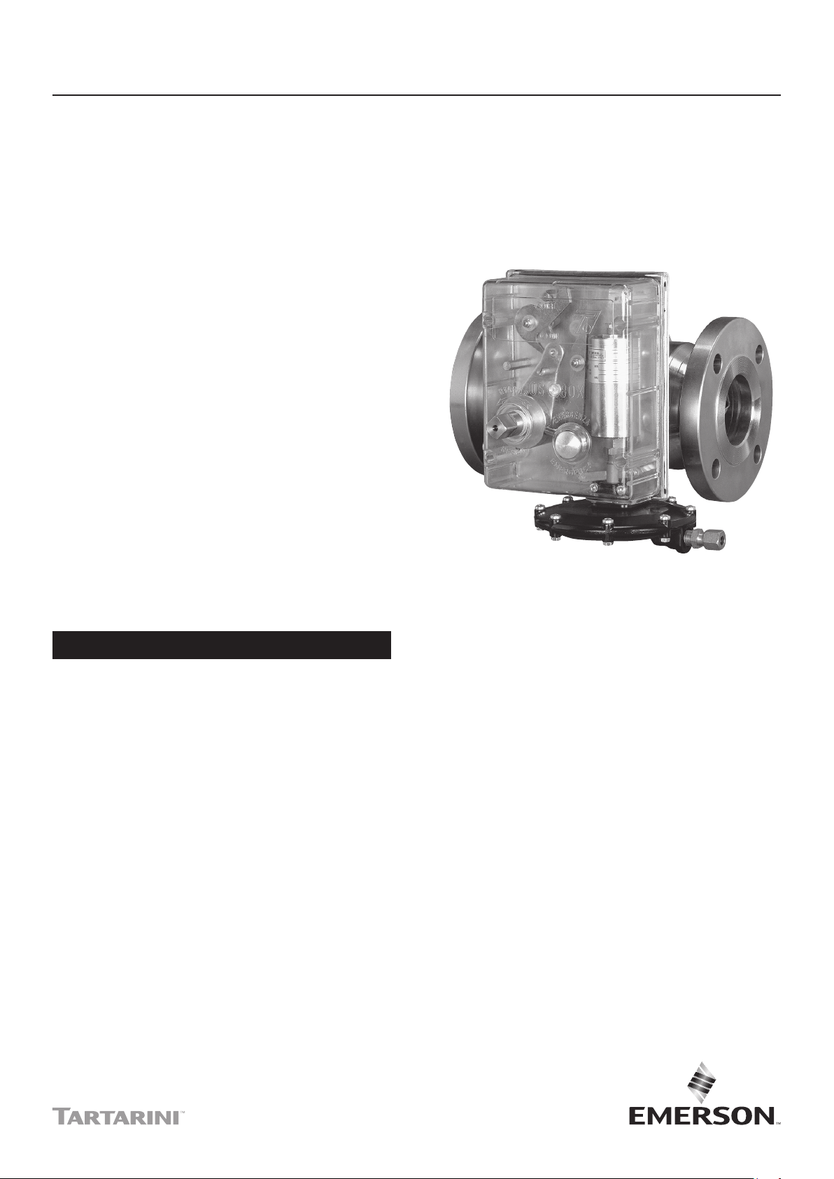
Figure 1. Type BM5A Slam-Shut Valve
Introduction
Scope of the Manual
This Instruction Manual provides instructions for
installation, startup, maintenance and spare parts
ordering for the Type BM5A slam-shut valves.
This manual also contains information for the
OS/80X Series slam-shut controller.
Product Description
The Type BM5A slam-shut valves are axial flow
type with a single seat and counterbalanced shutter.
They are designed for use in high pressure natural
gas transmission/city gate stations, large capacity
distribution systems and power plant feeds.
They provide smooth and reliable operation, tight
shutoff and long life.
Page 2

Type BM5A
Specifications
The Specifications section gives some general specifications for the Type BM5A slam-shut valve. The nameplates
give detailed information for a particular slam-shut valve as built in the factory.
Available Body Sizes
DN 25, 50, 80, 100 and 150 /
NPS 1, 2, 3, 4 and 6
Available End Connection Styles
CL300 RF and CL600 RF
Maximum Allowable Pressure
(1)
CL300 RF: 51.7 bar / 750 psig
CL600 RF: 103 bar / 1500 psig
(1)(2)
Maximum Operating Inlet Pressure (PS
max
)
CL300 RF: 50.0 bar / 725 psig
CL600 RF: 100 bar / 1450 psig
Inlet Pressure Range (bpu)
(1)(2)
CL300 RF: 0 to 50.0 bar / 0 to 725 psig
CL600 RF: 0 to 100 bar / 0 to 1450 psig
Overpressure Set Range (Wdo)
CL300 RF: 0.03 to 50.0 bar / 0.44 to 725 psig
CL600 RF: 0.03 to 80.0 bar / 0.44 to 1160 psig
Underpressure Set Range (Wdu)
CL300 RF: 0.01 to 50.0 bar / 0.15 to 725 psig
CL600 RF: 0.01 to 80.0 bar / 0.15 to 1160 psig
Accuracy Class (AG)
Up to ± 1%
Response Time (ta)
≤ 1 s
Minimum/Maximum Allowable Temperature (TS)
Class 1: -10 to 60°C / 14 to 140°F
Working Temperature Capabilities
(1)(2)
Standard Version, Nitrile (NBR) or
Fluorocarbon (FKM): -10 to 60°C / 14 to 140°F
Construction Materials
Slam-Shut Valve
Body: ASTM A105 Steel
Shutter: Steel
O-ring: Nitrile (NBR) or Fluorocarbon (FKM)
Pad: Nitrile (NBR) or Fluorocarbon (FKM)
Pad holder: Steel
OS/80X Series Slam-Shut Controller
Body: Aluminum (Types OS/80X-BP and
OS/80X-BPA-D) or Steel (Types OS/80X-MPA-D
and OS/80X-APA-D)
Diaphragm: Fabric-finished Nitrile (NBR)
O-ring: Nitrile (NBR)
Types OS/84X and OS/88X
Slam-Shut Controller
Body: Brass
Lip Seal: Polytetrafluoroethylene (PTFE)
O-ring: Nitrile (NBR)
Types PRX/181-PN, PRX/182-PN,
PRX-AP/181-PN and PRX-AP/182-PN Pilots
Body: Steel
Diaphragm: Fabric-finished Nitrile (NBR)
O-ring: Nitrile (NBR)
Slam-Shut Controller and Pilot Connection
1/4 NPT
Approximate Weights
See Table 3
(1)(2)
Accessories
• Proximity Switch or Micro Switch
for Remote Monitoring
• Solenoid Valve for Remote-controlled Closure
• IT/3V Three-Way Valve for Setting Control
Available Slam-Shut Controllers
See Table 2
1. The pressure/temperature limits in this Instruction Manual and any applicable standard or code limitation should not be exceeded.
2. Published values are in accordance with EN14382 specications.
This product is designed to be used with fuel gases of
1st and 2nd family according to EN 437 and with other
non-aggressive and non-fuel gases. For any other
gases, other than natural gas, please contact your
local Sales Office.
Use of gas pressure devices (safety shut-off
devices - SSD slam-shut type) shall comply with
EN 12186 and EN 12279.
Safety slam-shut valves manufactured by Emerson
must use additional pressure accessories (e.g.
controller or filters) manufactured or approved
by Emerson. Emerson is not responsible for any
possible inefficiency due to installation of additional
pressure accessories not manufactured or approved
by Emerson.
When pressure containing parts of safety slam-shut
device (SSD) valve and controller have different
maximum allowable pressures (PS), the SSD is
differential strength type.
2
Page 3
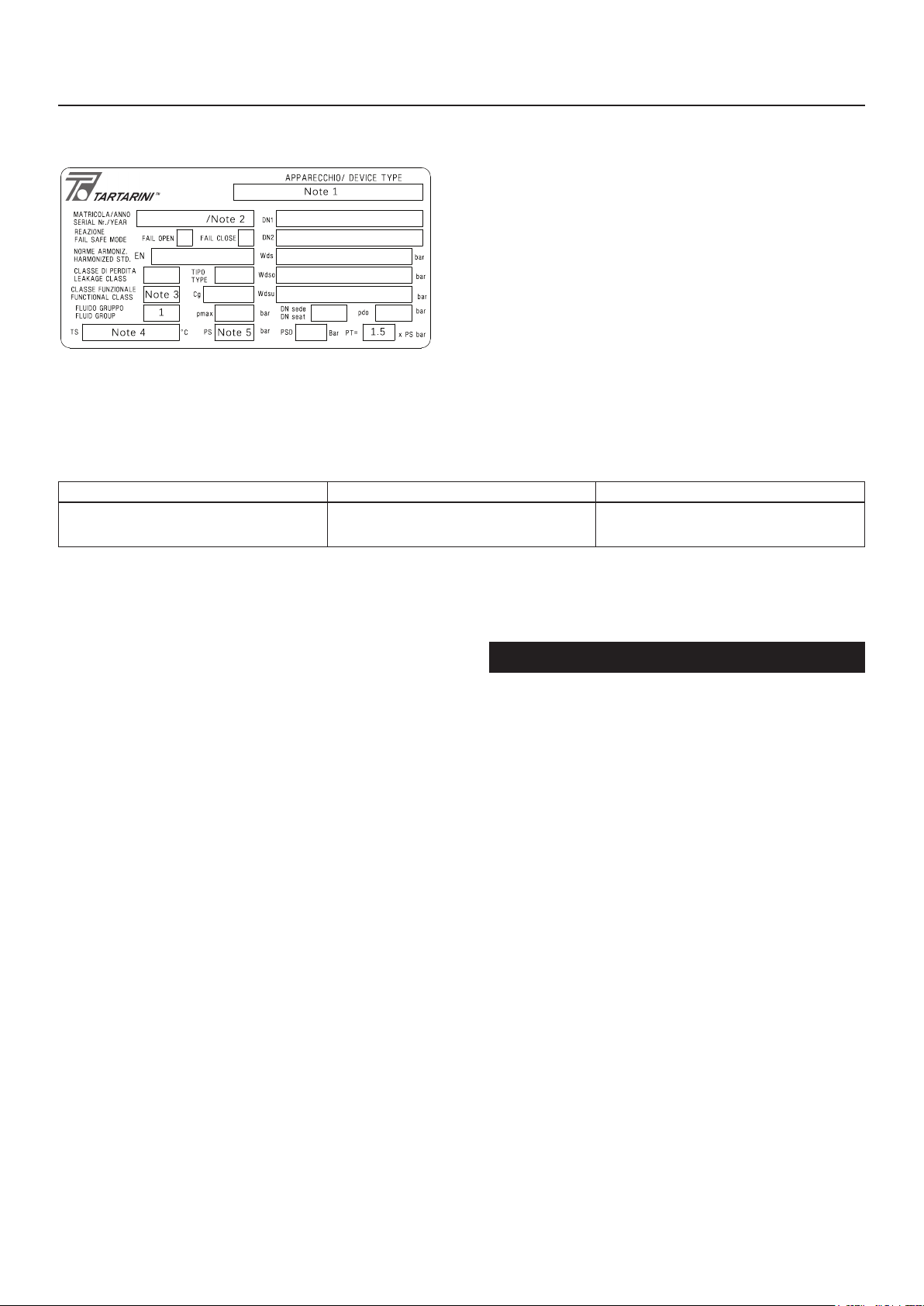
Note 1: See Body Size and End Connection Style
Note 2: Year of manufacture
Note 3: Class A or Class B
Note 4: Class 1: -10 to 60°C / 14 to 140°F
Note 5: Maximum Allowable Pressure (PS)
Figure 2. Type BM5A Slam-Shut Valves Nameplate
Table 1. PED Category for Type BM5A Slam-Shut Valves
PRODUCT SIZE CATEGORY FLUID GROUP
DN 25, 50, 80, 100, and 150 /
NPS 1, 2, 3, 4, and 6
IV 1
Only valves with overpressure and underpressure settings can be classied
in Class A.
CL300 RF: 50 bar / 725 psig
CL600 RF: 100 bar / 1450 psig
Type BM5A
Pressure Equipment Directive (PED)
Categories and Fluid Group
According to EN 14382, only in integral strength type
and Class A configuration (when both overpressure
and underpressure protections are set up) this
slam- shut valve can be classified like a safety
accessory according to PED.
The minimum PS between SSD valve and controller
shall be the PS of the safety accessory to comply the
provisions of EN 14382 about integral strength type.
This product, in its Class A and integral strength
configuration, is a safety accessory for pressure
equipment in the following PED 2014/68/EU
categories on Table 1.
Built-in pressure accessories (e.g. controllers
Types OS/80 and OS/80-X) conform to
PED Article 4 section 3 and were designed and
manufactured in accordance with sound engineering
practice (SEP).
Per Article 4 section 3, these “SEP” products must not
bear the CE marking.
ATEX Requirements
WARNING
▲
If the provisions of EN 12186 and
EN 12279, national regulations or any
specific manufacturer recommendations
are not put into practice before
installation and if purge by inert gas
is not carried out before equipment’s
start-up and shut-down operations,
a potential external and internal
explosive atmosphere can be present in
equipment and gas pressure regulating,
measuring stations or installations.
If a presence of foreign material in the pipelines is
foreseen and purge by inert gas is not carried out,
the following procedure is recommended to avoid any
possible external ignition source inside the equipment
due to mechanical generated sparks:
• Drainage to safe area via drain lines of foreign
materials, if any, by inflow of fuel gas with low
velocity in the pipe-work (5 m/sec.)
3
Page 4
Type BM5A
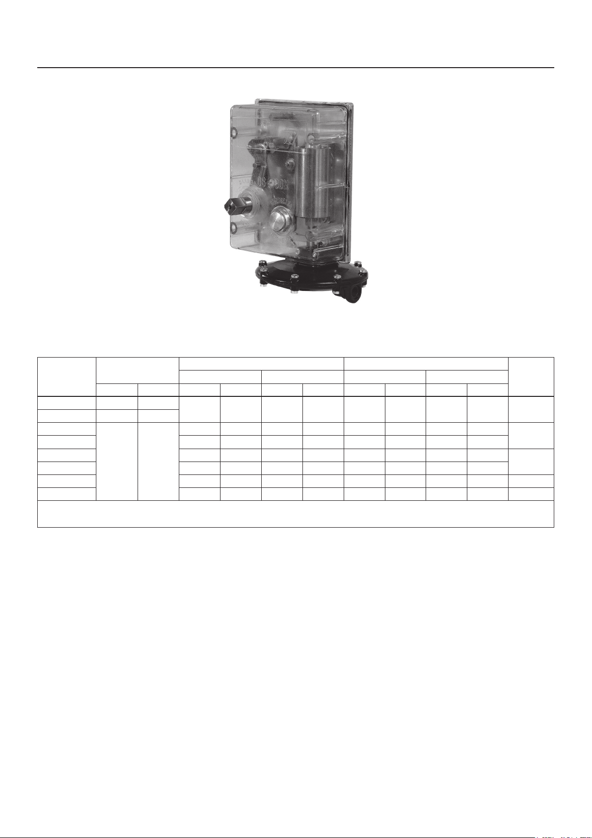
Figure 3. Type OS/80X-BP Slam-Shut Controller
Table 2. OS/80X and OS/80X-PN Series Slam-Shut Controller Details
TYPE
OS/80X-BP 5.0 73
OS/80X-BPA-D 20.0 290
OS/80X-MPA-D
OS/80X-APA-D 2.0 29 10.0 145 0.30 4.35 7.0 102
OS/84X 5.0 73 41.0 595 4.0 58 16.0 232
OS/88X 18.0 261 80.0 1160 8.0 116 70.0 1015
OS/80X-PN
OS/84X-PN
1. Type OS/80X-PN: Made of a Type OS/80X-APA-D, set at about 0.4 bar and Type PRX/182-PN pilot for overpressure and Type PRX/181-PN for underpressure as necessary to control the
system pressure. Type OS/84X-PN (Safety accessory): Made of a Type OS/84X, set at about 20 bar and Type PRX-AP/182-PN pilot for overpressure and Type PRX-AP/181-PN for underpressure as necessary to control the system pressure.
(1)
(1)
BODY RATING
bar psig bar psig bar psig bar psig bar psig
100 1450
OVERPRESSURE SET RANGE, W
Min Max Min Max
0.03 0.44 2.0 29 0.01 0.15 0.60 8.7 Aluminum
0.50 7.25 5.0 73 0.25 3.63 4.0 58
0.50 7.25 40.0 580 0.50 7.25 40.0 580 Steel
30.0 435 80.0 1160 30.0 435 80.0 1160 Brass
In any case,
• Provisions of Directive 1999/92/EC and 89/655/EC
shall be enforced by gas pressure regulating,
measuring station or installation’s end user.
• With a view to preventing and providing protection
against explosions, technical and/or organizational
DO
• External tightness test shall be carried out after
each reassembly at installation site using testing
pressure in accordance with national rules.
• Periodical check/maintenance for surveillance shall
be carried out complying with national regulations,
if any, and specific manufacturer recommendations.
UNDERPRESSURE SET RANGE, W
DU
BODY
MATERIAL
Steel
Brass
measures appropriate to the nature of the operation
shall be taken (e.g.: filling/exhausting of fuel
Principle of Operation
gas of internal volume of the isolated part/entire
installation with vent lines to safe area - 7.5.2 of
EN 12186 and 7.4 of EN 12279; monitoring of
settings with further exhaust of fuel gas to safe
area; connection of isolated part/entire installation
to downstream pipeline; ….)
• Provision in 9.3 of EN 12186 and 12279 shall be
enforced by pressure regulating/measuring station/
installation’s end user.
Slam-Shut Valve
Type BM5A slam-shut valve is made of an axial
flow valve and a controller which keeps the valve
open in normal conditions. The slam-shut valve
features a shutter valve sliding axially, therefore,
no by-pass is needed for its opening even in the
presence of pressurized gas. This valve can only
be opened manually by turning the eccentric
shaft counterclockwise.
4
Page 5
TYPE PS/79 OR PSA/79 PILOT
Type BM5A
BM5A SERIES
SLAM-SHUT VALVE
INLET PRESSURE, P
REGULATOR MOTORIZATION
PRESSURE, P
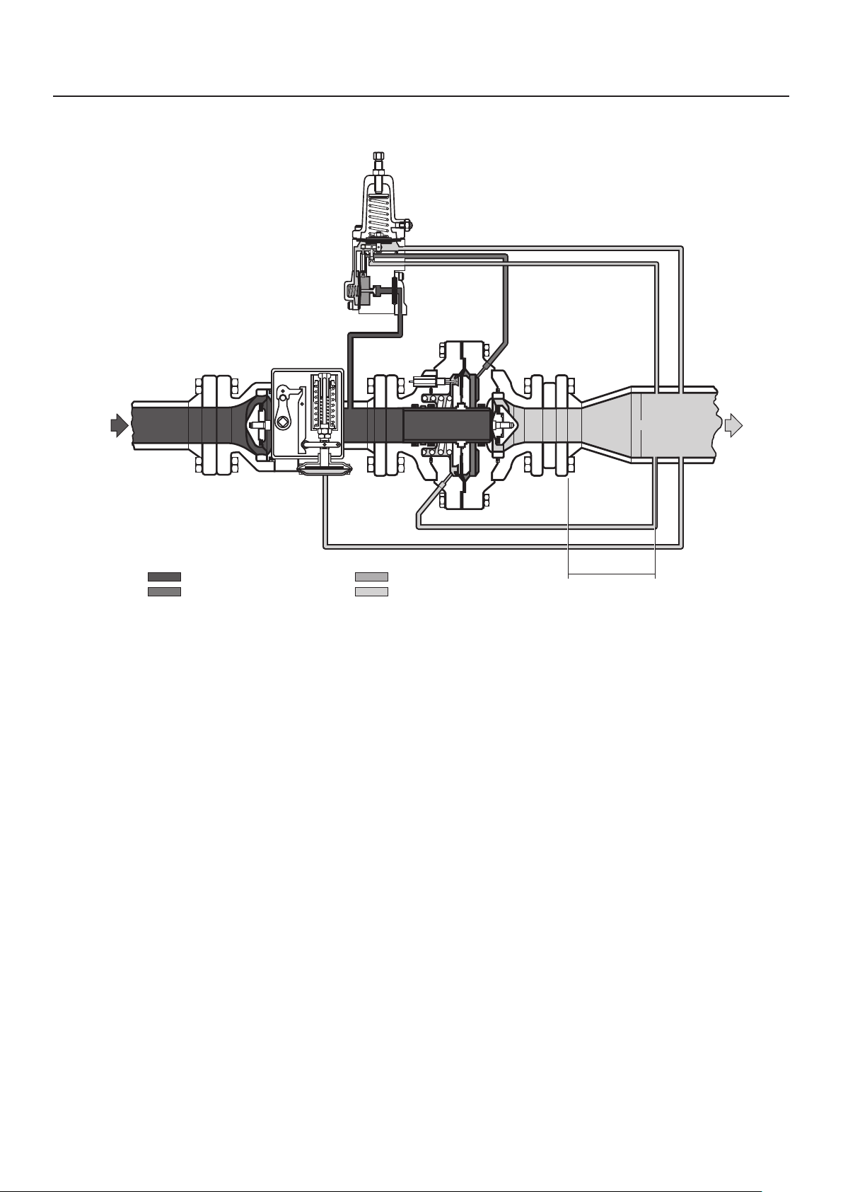
Figure 4. Type BM5A Slam-Shut Valve and Type FL or FLA1 Regulator Operational Schematics
u
m
TYPE FL OR FLA1
When the controlled pressure is within set values of
the slam-shut controller, the controller remains set and
prevents the rotation of the eccentric shaft, keeping
the valve open. When the controlled pressure varies
beyond setting limits, the controller releases the
eccentric shaft causing the valve close, following the
spring thrust.
The slam-shut controller has a manual release
push-button to quickly close the slam-shut valve
in case of emergency or during maintenance and
checking operations.
If the Type BM5A slam-shut valve is used with
pilot-operated pressure regulators, the supply
pressure to the pilot is taken from the downstream line
of the slam-shut valve. For this purpose, Type BM5A
slam-shut valve features a threaded hole which may
be used for the supply pressure to the pilot. This hole
is normally kept closed by a dowel.
STABILIZED PRESSURE, P
OUTLET PRESSURE, P
d
Slam-Shut Controller
The Type BM5A slam-shut valves are equipped with
the OS/80X or OS/80X-PN Series slam-shut controller.
The controllers are supplied in different models
according to set ranges required. The Type BM5A
with DN 150 / NPS 6 body size is equipped with a
reinforced version Type OS/80X-R.
OS/80X or OS/80X-PN Series slam-shut controller is
used to keep the slam-shut valve shutter open. These
Series are designed to operate on Overpressure
Shutoff (OPSO) only, Underpressure Shutoff (UPSO)
only, or Overpressure and Underpressure Shutoff
(OPSO/UPSO) protection.
Transport and Handling
Follow established transport and handling procedures
to avoid any damage on the pressure-containing parts
by shocks or excessive external pressure or stress.
Use appropriate eyebolts to aid in the handling of
heavy equipment.
Protect built-up sensing lines and pressure
accessories (e.g. slam-shut controller) from shocks or
excessive external pressure or stress.
D
REGULATOR
≥ 4D
up
5
Page 6
Type BM5A
OUTLET PRESSURE
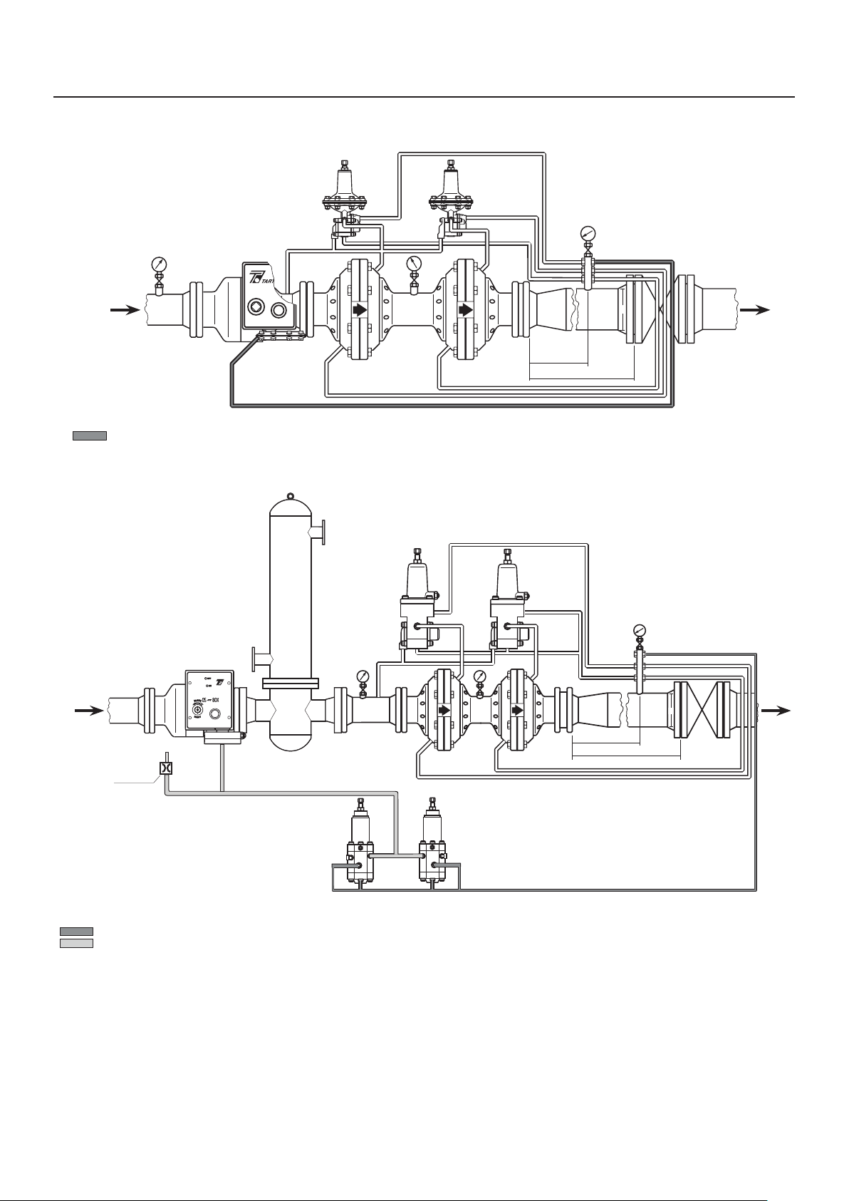
SLAM-SHUT VALVE WITH OS/80X SERIES CONTROLLER - INSTALLATION IN A LOW PRESSURE REGULATING LINE
BM5A SERIES
SLAM-SHUT VALVE
TYPE PS/79-1 TYPE PS/79-1
MONITOR
REGULATOR
D
≥ 4 X D
≥ 6 X D
BM5A SERIES
SLAM-SHUT VALVE
BLEED JET
(1 mm / 0.04 IN.)
OUTLET PRESSURE
ATMOSPHERIC PRESSURE
TYPE PRX/18-PN
PRX SERIES:
B - SUPPLY PORT
L - LOADING PORT
A - SENSING PORT
TYPE PS/79 OR PSA/79
B
A
TYPE S PSA/79, PSA/80,
PSA/79-AP AND PSA/80-AP:
V - SENSING PORT
M - SUPPLY PORT
R - LOADING PORT
S - BLEED PORT
TYPE
PS/79 OR
PSA/79
V
R
SMM
MONITOR REGULATOR
TYPE PRX/182-PN
LL
B
A
R
V
S
D
≥ 4 X D
≥ 6 X D
SLAM-SHUT VALVE WITH OS/80X-PN SERIES CONTROLLER - OVERPRESSURE AND UNDERPRESSURE CONTROL DOWNSTREAM OF REGULATORS
Figure 5. Type BM5A Typical Connection/Installation Schematics
6
Page 7

Type BM5A
Installation
WARNING
▲
Personal injury or equipment damage,
due to bursting of pressure-containing
parts may result if this slam shut valve
is overpressured or is installed where
service conditions could exceed the
limits given in the Specification section
and on the appropriate nameplate or
where conditions exceed any rating of the
adjacent piping or piping connections.
To avoid such injury or damage, provide
pressure-relieving or pressure limiting
devices to prevent service conditions
from exceeding those limits. Also, be sure
the installation is in compliance with all
applicable codes and regulations.
Additionally, physical damage to the slam
shut valve could break the slam shut
controller off the main valve, causing
personal injury and property damage due
to bursting of pressure containing parts.
To avoid such injury and damage, install
the slam shut valve in a safe location.
Installation procedures performed
by unqualified personnel may result
in improper adjustment and unsafe
operation. Either condition may result in
equipment damage or personal injury.
Only a qualified person shall install or
service the Type BM5A slam shut valve.
General Installation Requirements
• Ensure that the data found on the slam-shut valve
and slam-shut controller label are compatible with
usage requirements.
• Ensure the slam-shut is not damaged and remove
all foreign materials that might have collected
during shipping. Clean out all pipelines before
installing the slam-shut valve.
• Install the slam-shut valve in any position desired,
unless otherwise specified, but be sure flow
through the body matches the direction indicated
by the flow arrow stamped on the valve body.
• Install the slam-shut controller upright.
• Do not apply excessive external pressure or stress
on the body during installation.
• Use suitable line gaskets and bolting.
• Check and add any protection suitable for
specific environment.
• For outdoor installations, locate the slam-shut
devices away from vehicular traffic. Orient it in
correct position such that water, ice or other foreign
materials cannot enter into the device. Avoid
placing the slam-shut valve beneath eaves or
downspouts, and be sure it is above the probable
snow level. Install slam-shut valve in non-seismic
area and places away from fire or lightning.
• To avoid variations in the release values of
slam-shut valve and alteration of the trip pressure
setpoints of the slam-shut controller, make
pressure control line connection in a straight pipe
and away from bends, elbows or other areas of
turbulent flow.
Minimum and/or Maximum Setting
CAUTION
△
Slam shut controller must be mounted
as shown in Figure 6. If mounted
any other way, the controller will not
function properly.
• Follow the provisions of EN 12186 and EN 12279 in
installing Type BM5A slam-shut valve:
– Provide all means of appropriate draining
methods in the equipment installed before the
slam-shut valve.
– Provide the cathodic protection and electrical
isolation to avoid any corrosion.
– Clean the gas using proper filters, separators
or scrubber to avoid any hazard of erosion
or abrasion of pressure containing parts
(clause 7.3/7.2).
CAUTION
△
Whenever minimum or maximum
(UPSO or OPSO) pressure setting is not
required, omit corresponding steps.
The slam-shut controller is factory set at approximately
midpoint of the spring range or at customer specified
set pressure. However, a field adjustment may
be required to obtain desired results. Perform the
following steps to achieve the correct settings.
1. Make sure that the lever (key 33) is in horizontal
position when slam-shut controller is reset.
If necessary, use nut and locknut (keys 69
and 70) to adjust the lever (see step 2,
Reassembly section).
7
Page 8

Type BM5A
2. Use maximum (OPSO) adjusting nut (key 50)
to completely load maximum pressure (OPSO)
spring (key 53). Loosen minimum (UPSO)
adjusting screw (key 49) to completely relieve
minimum pressure (UPSO) spring (key 54).
3. Disconnect pressure control piping at port A.
4. Through port A, apply pressure to the controller
using a pump or other appropriate means and
raise the pressure to normal operating level.
5. Reset slam-shut controller. Then, reduce the
pressure until it reaches minimum cutoff level.
6. Use minimum (UPSO) adjusting screw (key 49) to
load minimum pressure (UPSO) spring (key 54)
slowly until the desired cut-off point is achieved.
7. Repeat steps (4) and (5) above to achieve the
required setpoint.
8. Bring pressure back to normal values.
9. Reset slam-shut controller. Then, raise the
pressure until it reaches maximum cut-off level.
10. Using maximum (OPSO) adjusting nut (key 50),
slowly unload maximum pressure (OPSO) spring
(key 53) until the desired cut-off point is achieved.
11. Repeat steps (8) and (9) above to achieve the
required setpoint.
Startup
WARNING
▲
Remove lever unit (key 137) from reset
stem (key 6) of controller immediately
after reset and secure it in a safe place.
If violated, equipment damage and/or
personal injury may result.
CAUTION
△
To prevent damage to the controller
during Startup, the sensing and bleed
lines should be located on the same
side of the downstream block valve.
When red mark in controller gets to
“ON”, resetting has been completed.
Further operation will damage the
controller. Based on structural
characteristics, the torque for resetting
first increases then decreases with the
increase of rotation of handle.
Slam-Shut Valve
Once the slam-shut valve is properly installed, perform
the following steps to startup.
Overpressure Protection
The recommended maximum allowable pressures are
stamped on the slam-shut valve label.
Provide upstream overpressure protection if
inlet pressure to slam shut valve can go higher
than maximum allowable/operating pressure to
downstream equipment.
After slam-shut valve’s intervention, inspect the
slam-shut valve for damage and maintain downstream
side pressure within the actual maximum operating set
up range to avoid abnormal back pressures that can
damage the SSD’s controller.
Provide downstream overpressure protection if the
slam-shut valve outlet pressure can be greater than
the maximum allowable pressure (PS) of the pilot
(differential strength type).
Slam-shut valve operation below the limits specified
in the specifications section and slam-shut valve label
does not preclude the possibility of damage from
external sources or debris in the line.
1. Partially open t
downstream of the regulator enough to allow a
minimum gas flow.
2. Partially open isolation valve upstream of the
slam-shut valve to let a small amount of gas to
flow into the slam shut valve.
3. Turn the reset stem slowly counterclockwise using
the appropriate lever unit. This will let gas to flow
from inlet to outlet of slam-shut valve.
4. Wait for few seconds for the pressure to stabilize.
5. Repeat step 3 above, making sure that levers of
slam-shut controller keep the valve open and that
lever (key 33) is in horizontal position.
6. Slowly open the isolation valve upstream
of slam-shut valve completely. Then, slowly
open the isolation valve downstream of
regulator completely.
he isolation valve located
8
Page 9

Type BM5A
Slam-Shut Controller Adjustment
Perform the following steps to change the
slam-shut controller setpoints (overpressure
and/or underpressure).
1. Remove the spring closing cap of the controller.
2. Turn the adjusting screws clockwise to increase
setpoint or counterclockwise to decrease setpoint.
Monitor set pressure with a test gauge during
the adjustment.
Shutdown
WARNING
▲
To avoid personal injury resulting from
sudden release of pressure, isolate
the slam-shut valve from all pressure
and release trapped pressure from the
equipment and pressure line before
disassembly of equipment. In case of
disassembly of pressure retaining parts
for checks and maintenance procedures,
external and internal tightness
tests have to be done according to
applicable codes.
before applying the CE marking, shall also be covered
after every subsequent reassembly at installation
site, in order to ensure that the equipment will be safe
throughout its intended life.
The slam-shut device should be tested for both under
and overpressure shutoff activation and seat leak
annually with test intervals not to exceed 15 months
and at least one each calendar year. If the slam-shut
device does not close at the desired set pressure(s)
and/or leaks gas after closure, repair and/or replace
the slam-shut device.
Slam-Shut Valve (See Figure 7)
WARNING
▲
Only a qualified person may perform
maintenance procedures. If necessary,
contact our local Sales Office
for assistance.
Before proceeding with any
maintenance work, stop the fluid flow
to the unit. Turn off the isolation valves
upstream and downstream of the
slam-shut valve. Release pressure from
the equipment and control lines.
Maintenance
WARNING
▲
Only a qualified person may perform
maintenance procedures. If necessary,
contact our local Sales Office
for assistance.
Failure to test the slam-shut device for
proper shutoff can result in a hazardous
condition. Test the slam-shut device for
operation per applicable federal, state,
and local codes, rules and regulations,
and manufacturer’s instructions.
The slam shut valve and its accessories are subject
to normal wear and therefore, they must be inspected
periodically and replaced if necessary. The frequency
of inspection and replacement depends on the severity
of service conditions, test results found during the
annual test, and applicable codes and regulations. In
accordance with applicable National or Industry codes,
standards and regulations/recommendations, all
hazards covered by specific tests after final assembly
Disassembly
1. Disconnect all connections, remove slam-shut
valve from the line and place it in vertical position
(inlet flange at bottom and outlet flange at top).
Use appropriate protection method to prevent
damage to the flanges and their gasket surfaces.
2. Mark the position of the outlet flange (key 116) and
inlet flange (key 100) to keep the same/correct
alignment during reassembly.
3. Loosen the special screws (key 133) and dismount
the slam-shut controller.
4. Loosen screws (key 135) and remove hub
(key 124). Remove seeger ring (key 122) and
dismount parts. Replace O-rings [keys 120,125
and 126 (include key 130 for DN 150 / NPS 6)]
and anti-friction rings (key 119). Check bearing
[key 128 (include key 131 for DN 150 / NPS 6)]
and replace if necessary.
5. Slowly loosen nuts (key 112) to decompress the
spring (key 114).
6. Remove sleeve (key 117), disk (key 110) and
pad holder (key 101); loosen screw (key 104)
and replace pad unit (key 102). Replace O-ring
[key 107 (include key 129 for DN 65 / NPS 2-1/2
to DN 150 / NPS 6)].
9
Page 10

Type BM5A
7. Replace O-ring (key 115).
8. Check all moving parts, especially nickel plated
surfaces. Replace any that are worn or damaged.
9. Clean all stripped-down parts.
Reassembly
Lubricate all seals with silicone-based lubricant and be
careful not to damage the seals when reassembling.
Reassemble the parts in the reverse order of the
above steps.
As you proceed, make sure that parts move freely and
without too much friction.
In addition:
• Complete reassembly and make sure to tighten all
screws uniformly.
• When reassembling the hub (key 124), make sure
that the pawl of shaft unit (key 121) is facing the
inlet flange (key 100).
• Check that slam-shut sleeve (key 117) opens when
shaft unit (key 121) is rotated counterclockwise.
• Before reassembling the slam-shut controller, make
sure that the pawl of shaft unit (key 121) is against
the sleeve (key 117). Ensure that the slam-shut
actuator is correctly mounted.
• After reassembling check if all parts are properly
functioning. Check the valve with suds to ensure
that there are no leaks.
• Reinstall slam shut valve on the line and reestablish
all connections.
Routine slam-shut controller maintenance
entails periodic checking of the diaphragm on
the Type OS/80X (the piston Gaco flex on the
Type OS/84X) and the movement of the levers (the
levers should move freely with minimum friction). If
necessary, lubricate pins with silicone-based lubricant.
Disassembly
1. Remove screws (key 40) and casing (key 47).
2. Remove dowels (key 12) and bushing (key 13).
3. Slide off stem (key 6), lever assembly (keys 17
and 2), balls (key 10) or rollers for Type OS/80X-R
and shim ring (key 15). Wash parts, replace any
if worn-out.
4. Remove nuts (key 18), levers (keys 20 and 36)
and springs (keys 37 and 21).
5. Remove nut (key 30), screw (key 29) and lever
(key 33).
6. Remove minimum (UPSO) adjusting screw
(key 49), maximum (OPSO) adjusting nut (key 50)
and springs (keys 53 and 54).
7. Remove cover (key 61) on OS/80X Series or plug
on Types OS/84X and OS/88X, and proceed as
directed in replacing diaphragm/O-ring section.
8. Remove nut (key 70) and locknut (key 69), then
slide off stem unit (key 57).
9. Loosen screw (key 3), unscrew nut (key 9),
remove balls holder (key 5) and check seals
(keys 4 and 8) for wear.
Slam-Shut Controller (See Figure 8)
WARNING
▲
Only a qualified person may perform
maintenance procedures. If necessary,
contact our local Sales Office
for assistance.
Before proceeding with any
maintenance work, disconnect impulse
connection (A) to release pressure
inside the slam-shut controller.
After maintenance operation, check the
tightness of the connections with suds.
10
10. Clean all removed parts. Replace any that are
worn or damaged.
Replacing Diaphragm (OS/80X Series only)
1. Remove screws (key 27) and cover (key 61).
2. Replace diaphragm (key 62).
3. To remount diaphragm, coat it with grease, set
it in place around the edge of cover (key 61)
and evenly tighten screws (key 27) to ensure
proper sealing.
Page 11

Type BM5A
Replacing O-ring
(Types OS/84X and OS/88X only)
1. Remove plug (key 61) and extract piston (key 68)
from body (key 60).
2. Replace O-ring (key 67) and Gaco flex (key 66).
3. Reassemble in the reverse order of the
above procedures.
Reassembly
Reassemble all parts in the reverse order of the steps
in the disassembly section.
As you proceed, make sure all parts move freely
without too much friction. If necessary, lubricate them
with silicone-based lubricant.
Make sure to:
1. Screw the nuts (keys 30 and 18) without
overtightening them to allow the levers (keys 33,
36 and 20) to move freely without friction.
2. Before mounting minimum (UPSO) spring
(key 54), register position of lever (key 33) by
means of nut (key 70), locking it into place with
locknut (key 69).
Note
The lever (key 33) is in proper position
when it is exactly horizontal and in the
center of the groove of lever (key 36).
3. Remount lever assembly (keys 17 and 2), balls
(key 10) or rollers for Type OS/80X-R, keeping
them in their seat with grease and stem (key 6),
which is to be turned so the balls/rollers enter their
seats. The stem and lever assembly should now
be tightly fitted together.
4. Remount bushing (key 13); make sure that the
dowels (key 12) are firmly set in the grooves of the
stem (key 6).
5. Repeatedly check if pilot resets properly and,
lastly, remount minimum (UPSO) spring (key 54).
6. Check controller setting.
Periodical Checks
Perform the following procedures to check that the
slam-shut valve is working properly.
Cut-off Test
1. Cut-off the fluid flow to slam shut valve by
closing upstream and downstream isolation
valves and disconnect the pressure sensing line
to port A of slam shut controller. The slam-shut
controller should cut-off for minimum pressure
(Underpressure Shut-off - UPSO), if set.
2. Through port A, using a small pump or other
appropriate means, raise the pressure to normal
operating level. Reset slam-shut controller if it was
cut-off in step 1.
3. Simulate pressure increase until maximum
pressure cutoff value (Overpressure Shut-off –
OPSO) is reached. The slam-shut valve should
cut-off at this point.
4. Connect the sensing line back to port A of the
controller and return the slam shut valve to
operating conditions by following the instructions
described in the Startup section.
Valve-seal Check
1. Slowly close the downstream isolation valve.
2. Press the “EMERGENCY” button. The slam-shut
controller should immediately close and cut-off the
flow through the valve.
3. Loosen a connector in the downstream line of
the slam-shut valve or of the regulator. Check
the connector with soap and water, to make sure
there are no leaks; repair the slam-shut valve
if necessary.
Parts Ordering
When corresponding with our local Sales Office about
this equipment or to order spare parts or kit, always
refer to the type of slam-shut valve or slam-shut
controller and its serial number.
When ordering replacement parts, reference the key
number of each needed part as found in the following
parts list.
Spare Parts
Store spare parts in compliance with national
standard/rules to avoid over aging or any damage.
11
Page 12

Type BM5A
FLOW FROM RIGHT TO LEFT FLOW FORM LEFT TO RIGHT
UPWARD FLOWDOWNWARD FLOW
Figure 6. Type BM5A Slam-Shut Valve Flow Orientation
Table 3. Approximate Weights
END
CONNECTION STYLE
CL300 RF / CL600 RF 17 37.5 30 66 62 137 105 231 280 617
12
DN 25 / NPS 1 DN 50 / NPS 2 DN 80 / NPS 3 DN 100 / NPS 4 DN 150 / NPS 6
kg lbs kg lbs kg lbs kg lbs kg lbs
Page 13

Type BM5A
Table 4. Troubleshooting Guide for Type BM5A Slam-Shut Valve
SYMPTOMS POSSIBLE CAUSE RECOMMENDED ACTIONS
Slam-shut device does not remain set.
Sleeve does not seal properly.
Parts List
Type BM5A Slam-Shut Valve
(See Figure 7)
Key Description
100 Inlet ange
101 Pad holder
102* Pad unit
103 Pad retainer
104 Screw
105 Label
106 Rivet
107* O-ring
108 Label support
109 Label
110 Disk
111 Washer
112 Nut
113 Stud bolt
114 Spring
115* O-ring
116 Outlet ange
117 Sleeve
118 Screw
The sensing line to port (A) of slam-shut controller
is not connected properly.
Downstream pressure coincides with the maximum
or minimum (OPSO or UPSO) slam-shut settings.
Diaphragm (key 62) [or Gaco ex (key 66) on
Types OS/84X and OS/88X] is damaged.
Seal gaskets are worn out. Check gaskets and replace as necessary.
Sleeve has dirt deposits. Check sleeve and clean as necessary.
Shaft unit (key 121) is damaged. Check shaft unit and repair or replace as necessary.
Key Description
119* Anti-friction ring
120* O-ring
121 Shaft unit
122 Seeger ring
123 Pin
124 Hub
125* O-ring
126* O-ring
127 Disk
128 Bearing
129* O-ring
130* O-ring
131 Bearing
132 Spacer
133 Special screw
134 Bushing
135 Screw
136 Eyebolt
137 Lever unit
Check the sensing line connections (A).
Check slam-shut settings.
Replace the diaphragm or Gaco Flex.
* Rubber parts are supplied in the “spare parts kit”, recommended as stock.
13
Page 14

Type BM5A
OS/80X Series Slam-Shut Controller
(See Figure 8)
Key Description
1 Plate
2 Releasing bushing
3 Screw
4* Gasket
5 Balls holder
6 Stem
7 Roller
8* O-ring
9 Reloading nut
10 Ball (Roller for Type OS/80X-R)
11 Roller
12 Dowels
13 Reloading bushing
14* O-ring
15 Ring
17 Reloading lever unit
18 Self-locking nut
19 Washer
20 Return lever
21 Spring
22 Fulcrum
24 Label
26 Nut
27 Screw
28 Reloading pin
29 Screw
30 Self-locking nut
31 Washer
32 Plate fulcrum
33 Lever
34 Screw
35 Cone
36 Releasing lever
37 Spring
38 Plug
39 Locking pin
Key Description
40 Screw
41 Indicator pin
42 On-O indicator
43 Button
44* O-ring
45 Spring
46 Gasket
47 Casing
48 Screw
49 Minimum pressure (UPSO) adjusting screw
50 Maximum pressure (OPSO) adjusting nut
51 Pipe assembly
52 Washer
53 Spring
54 Spring
55 Lower spring holder unit
56 Seeger ring
57 Stem unit
58 Spring
59 Plate holding stem unit
60 Top cover (Body for Types OS/84X and OS/88X)
61 Lower cover (Plug for Types OS/84X and OS/88X)
62* Diaphragm
63 Screw
64 Block
65* O-ring
66* Gaco ex
67* O-ring
68 Piston
69 Locknut
70 Nut
71 Microswitch
73* Gasket (only for Types OS/80X-BP, -BPA-D and -MPA-D)
74 Filter
* Rubber parts are supplied in the “spare parts kit”, recommended as stock.
14
Page 15

Type BM5A
OFF
ON
R
M
A
I
O
T
E
E
S
OS-80X
G
R
E
M
E
E
M
E
R
G
E
N
Z
A
Y
C
N
E
R
R
105
104103102101
106 107 109 106 110 111 112 113100
125126127128
124
123
122
121
108
120 119
114 115
116
117
118
MLM1499
Figure 7. Type BM5A Slam-Shut Valve Assembly
15
Page 16

Type BM5A
136
PAD HOLDER
DN 65 / NPS 2-1/2 TO
DN 150 / NPS 6
101
133
137 137
DN 150 / NPS 6 LEVER UNIT
135
DN 150 / NPS 6 REOPENING HUB
MLM1499
16
102
103
104
129
119 120
134
133
124125
Figure 7. Type BM5A Slam-Shut Valve Assembly (continued)
126
122
123
135
128
130
131
132
131
121
Page 17

10
Type BM5A
5
DETAIL OF TYPE OS/80X-R REINFORCED
FOR TYPE BM5A DN 150 / NPS 6
2220 21
19
18
17
6
40
71
DETAIL OF OS/80X SERIES
WITH PROXIMITY SWITCH
OFF
1
ON
SECTION D-D
2
MLM1389
15
1314
12 11
SECTION C-C
3
4
R
M
A
I
O
5
R
6
7
R
8
OS-80X
T
E
E
S
G
R
E
M
E
E
M
E
R
G
9
10
Figure 8. OS/80X Series Slam-Shut Controller Assembly (Standard Version)
E
N
Z
A
Y
C
N
E
17
Page 18

Type BM5A
41
42 19 18 43
4544
29
30
31
32
38 3722
SECTION A-A
C
D D
A
28
39
36
3435
26
47 48 49 50 51
46
B
52
53
54
52
24
OMT
33
70
69
48
73
55
56
57
58
59
MLM1389
18
A
C
27 26
Figure 8. OS/80X Series Slam-Shut Controller Assembly (Standard Version) (continued)
B
A
SECTION B-B
60
62
61
Page 19

Type BM5A
65 62 61
59 63 64 60
34
27
TYPE OS/80X-APA-D DETAIL TYPE OS/80X-MPA-D DETAIL
34 59 63
6465 60
62 61
74
74 74
65 34 59 63 64 60 62 61
73
27
34 59 63
64
6660
67
73
27
68
TYPE OS/80X-BPA-D DETAIL TYPE OS/84X DETAIL
59
34
68
63 64 60 66 67
61
61
MLM1389
TYPE OS/88X DETAIL
Figure 8. OS/80X Slam-Shut Controller Assembly (Standard Version) (continued)
19
Page 20

Type BM5A
Webadmin.Regulators@emerson.com
Tartarini-NaturalGas.com
Facebook.com/EmersonAutomationSolutions
LinkedIn.com/company/emerson-automation-solutions
Twitter.com/emr_automation
Emerson Automation Solutions
Americas
McKinney, Texas 75070 USA
T +1 800 558 5853
Asia Pacic
Singapore 128461, Singapore
T +65 6777 8211
+1 972 548 3574
Europe
Bologna 40013, Italy
T +39 051 419 0611
Emerson Process Management s.r.l.
Emerson Automation Solutions - Stabilimento di/Site of: Castel Maggiore - Bologna
Sede Legale/Legal Entity: Piazza Meda 5, 20121 Milano, Italy
Sede Amministrativa/Administrative Headquarters: OMT Tartarini, Via Clodoveo Bonazzi 43,
40013 Castel Maggiore (Bologna), Italy
C.F. - P.I. e R.I. di MI 13186130152 - REA di MI/n.1622916
Direz. e Coord. (art. 2497 bis CC): EMERSON ELECTRIC CO. St. Louis (USA) Socio Unico
Middle East and Africa
Dubai, United Arab Emirates
T +971 4 811 8100
D103580X012 © 2021 Emerson Process Management Regulator
Technologies, Inc. All rights reserved. 01/21.
The Emerson logo is a trademark and service mark of Emerson Electric
Co. All other marks are the property of their prospective owners.
Tartarini™ is a mark owned by O.M.T. Ocina Meccanica Tartarini s.r.l.,
a business of Emerson Automation Solutions.
The contents of this publication are presented for informational
purposes only, and while every eort has been made to ensure their
accuracy, they are not to be construed as warranties or guarantees,
express or implied, regarding the products or services described herein
or their use or applicability. All sales are governed by our terms and
conditions, which are available upon request. We reserve the right to
modify or improve the designs or specications of such products at any
time without notice.
Emerson Process Management Regulator Technologies, Inc does not
assume responsibility for the selection, use or maintenance of any
product. Responsibility for proper selection, use and maintenance of any
Emerson Process Management Regulator Technologies, Inc. product
remains solely with the purchaser.
 Loading...