

Emerson Bettis RTS CL Series, Bettis CL-15, Bettis CL-05, Bettis CL-25, Bettis CL-15A-1M0HE User Instructions
...Page 1
User Instructions
MAN-02-04-60-0350-EN Rev. 3
February 2019
Operating Manual for Bettis RTS CL Series
Compact Linear Electric Actuator
Page 2

Page 3

User Instructions
MAN-02-04-60-0350-EN Rev. 3
Table of Contents
Section 1: Introduction
Section 2: General
2.1 Actuator Overview ........................................................................................ 3
2.2 Serial Number and Type Label ....................................................................... 5
2.3 Operating Mode ............................................................................................ 5
2.4 Protection Class ............................................................................................ 6
2.5 Mounting Position ......................................................................................... 6
2.6 Direction of Rotation ..................................................................................... 7
2.7 Protection Devices ........................................................................................ 8
2.8 Ambient Temperature ................................................................................... 8
2.9 Delivery Condition of the Actuators .............................................................. 9
2.10 Information Notice (Tag) ............................................................................... 9
Table of Contents
February 2019
Section 3: Packaging, Transport and Storage
3.1 General ....................................................................................................... 10
3.2 Storage ....................................................................................................... 10
3.3 Long-term Storage ...................................................................................... 11
Section 4: Assembly and Disassembly of Linear Units on Valves
4.1 Security and Assembly Instructions ............................................................. 12
4.2 Mechanical Connection ............................................................................... 13
4.3 Disassembly ................................................................................................ 13
4.4 Mounting Postion of the Operating Unit ...................................................... 14
4.5 Electrical Connection .................................................................................. 15
Section 5: Commisioning
5.1 General ....................................................................................................... 18
5.2 Manual Operation ....................................................................................... 18
5.3 Mechanical Default Settings and Preparation .............................................. 18
5.4 End Limit Setting ......................................................................................... 18
5.5 Final Step ....................................................................................................25
Section 6: Control Unit
6.1 Operating Unit ............................................................................................ 26
6.2 Display Elements ......................................................................................... 27
6.3 Operation ................................................................................................... 29
Table of Contents
i
Page 4

Table of Contents
February 2019
User Instructions
MAN-02-04-60-0350-EN Rev. 3
Section 7: Parameter Menu
7.1 Parameter Group: End Limit ........................................................................ 38
7.2 Parameter Group: Torque ............................................................................ 40
7.3 Parameter Group: Speed ............................................................................. 41
7.4 Parameter Group: Ramp (option) ................................................................ 41
7.5 Parameter Group: Control ........................................................................... 42
7.6 Parameter Group: Password ........................................................................ 42
7.7 Parameter Group: Position .......................................................................... 43
7.8 Parameter Group: Binary Inputs .................................................................. 43
7.9 Parameter Group: Binary Outputs ............................................................... 46
7.10 Parameter Group: Position Output (option) .................................................49
7.11 Parameter Group: Step Mode ...................................................................... 51
7.12 Parameter Group: Positioner (option) ..........................................................53
7.13 Parameter Group: PID Controller (optional) ................................................. 55
7.14 Parameter Group: Probus-DP (option) ....................................................... 57
7.15 Parameter Group: DeviceNet (option) ......................................................... 57
7.16 Parameter Group: Characteristic Curves (optional) ......................................58
7.17 Parameter Group: Identication (option) .....................................................59
7.18 Parameter Group: System Parameters (locked) ........................................... 59
7.19 Parameter Group: Miscellaneous ................................................................. 59
Section 8: Status Area
8.1 Status .......................................................................................................... 61
8.2 History ........................................................................................................ 64
Section 9: Infrared Connection
Section 10: Bluetooth Link
Section 11: Maintenance
11.1 Service/Exchange of Spindel Nut and Axial Bearing ...................................... 68
11.2 Moving Interval ........................................................................................... 68
11.3 Greasing Interval ......................................................................................... 68
Section 12: Troubleshooting
12.1 Error List...................................................................................................... 69
ii
Table of Contents
Page 5

User Instructions
MAN-02-04-60-0350-EN Rev. 3
Section 13: Fuses
Section 14: Lubricant Recommendation and Requirements
Section 15: Training
Section 16: Technical Data and Certifications
Table of Contents
February 2019
14.1 Main Body: -25 to +60°C .............................................................................. 72
14.2 Output Type A and Spindle Drives (Linear Actuators) -40 to +85°C ..............72
14.3 Basic Lubricant Service Interval ................................................................... 72
16.1 Binary Outputs ............................................................................................ 75
16.2 Binary Inputs ............................................................................................... 76
16.3 Analogue Inputs .......................................................................................... 80
16.4 Analogue Output ........................................................................................ 80
16.5 Auxiliary Voltage Input and Output ............................................................. 82
16.6 Connections ............................................................................................... 83
16.7 Miscellaneous .............................................................................................83
Table of Contents
iii
Page 6

Section 1: Introduction
February 2019
Section 1: Introduction
These operating instructions apply to Bettis RTS CL Series of Compact Linear actuators.
The scope of application covers the operation of industrial valves, e.g., globe valves, gate
valves, buttery valves and ball valves. For other applications please consult with
the factory.
The manufacturer shall not be liable for incorrect use and possible damage arising thereof.
The risk shall be borne solely by the user.
Using the unit as intended also entails the observance of these operating instructions.
CAUTION: OBSERVE HAZARDOUS VOLTAGE LEVEL
When operating electrical equipment, certain parts inevitably carry hazardous voltage
levels. Work on the electrical system or equipment must be carried out only in accordance
with electrical regulations by a qualied electrician himself or by specially instructed
personnel under the control and supervision of a qualied electrician.
User Instructions
MAN-02-04-60-0350-EN Rev. 3
Maintenance instructions must be observed as otherwise the safe operation of the actuator
cannot be guaranteed.
Failure to follow the warning information may result in serious bodily injury or property
damage. Qualied personnel must be thoroughly familiar with all warnings contained in
this operating manual.
Proper transport, storage, installation, assembly and careful commissioning are essential to
proper and safe operation.
WARNING: ALWAYS REFER TO STANDARDS
When working in potentially explosive areas, observe the European Standards EN 60079-14
”Electrical In- stallations in Hazardous Areas” and EN 60079-17 ”Inspection and
Maintenance of Electrical Installations in Hazardous Areas”.
Maintenance work on open actuators may only be conducted if these are de-energized.
Reconnection during maintenance is strictly prohibited.
1
Introduction
Page 7

User Instructions
MAN-02-04-60-0350-EN Rev. 3 February 2019
Section 2: General
Section 2: General
Linear units are offered in three variants CL05, CL15, CL25. The linear adaptions are
mounted to the Compact Multi-turn (CM) series to drive linear positioning movement.
The linear unit converts the torque output from the actuator into an axial force.
The combination of actuator and linear unit, is based on the required thrust and the
necessary stroke.
General
2
Page 8

Section 2: General
February 2019
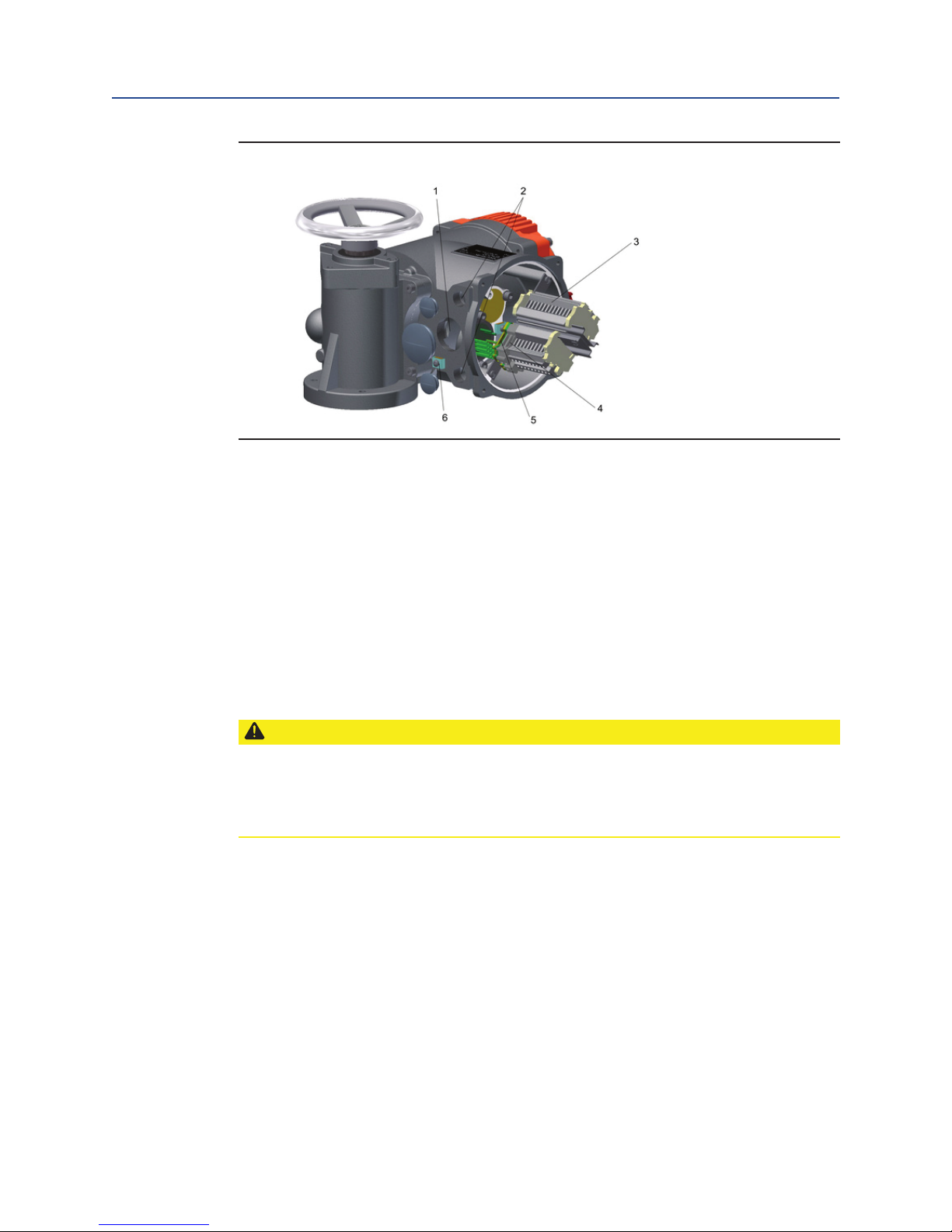
2.1 Actuator Overview
Figure 1 The Bettis RTS Series Compact Linear Actuator
User Instructions
MAN-02-04-60-0350-EN Rev. 3
Parts Overview:
1. Handwheel
2. Control unit (Operating unit)
3. Connection compartment
4. Gear component
3
General
Page 9
User Instructions
MAN-02-04-60-0350-EN Rev. 3 February 2019
Section 2: General
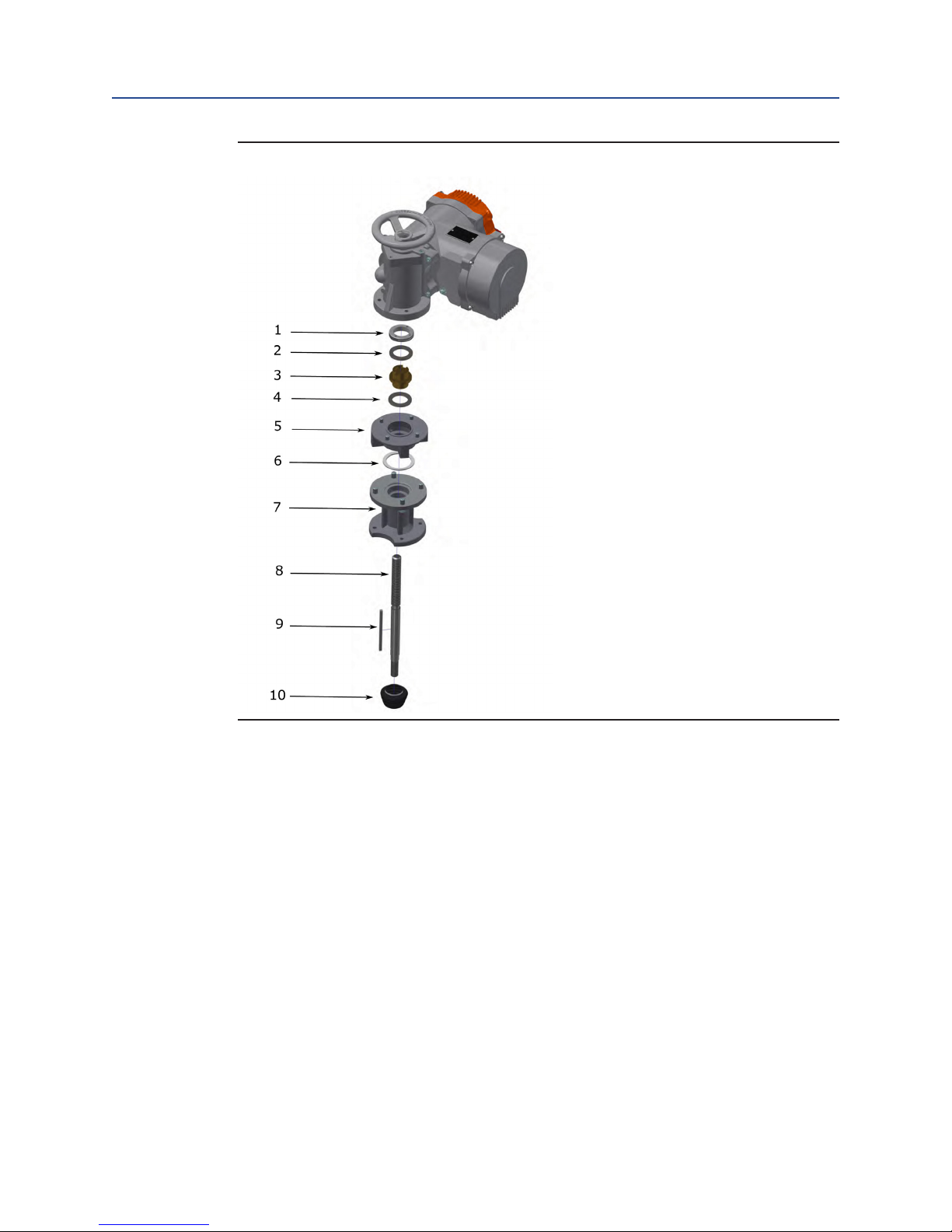
Figure 2
General
Parts Overview:
1. Ring nut
2. Axial bearing
3. Spindle nut
4. Axial bearing
5. Output ange
6. Centering ring
7. Housing linear unit
8. Spindle
9. Key
10. Bellows
4
Page 10
Section 2: General
y,
February 2019
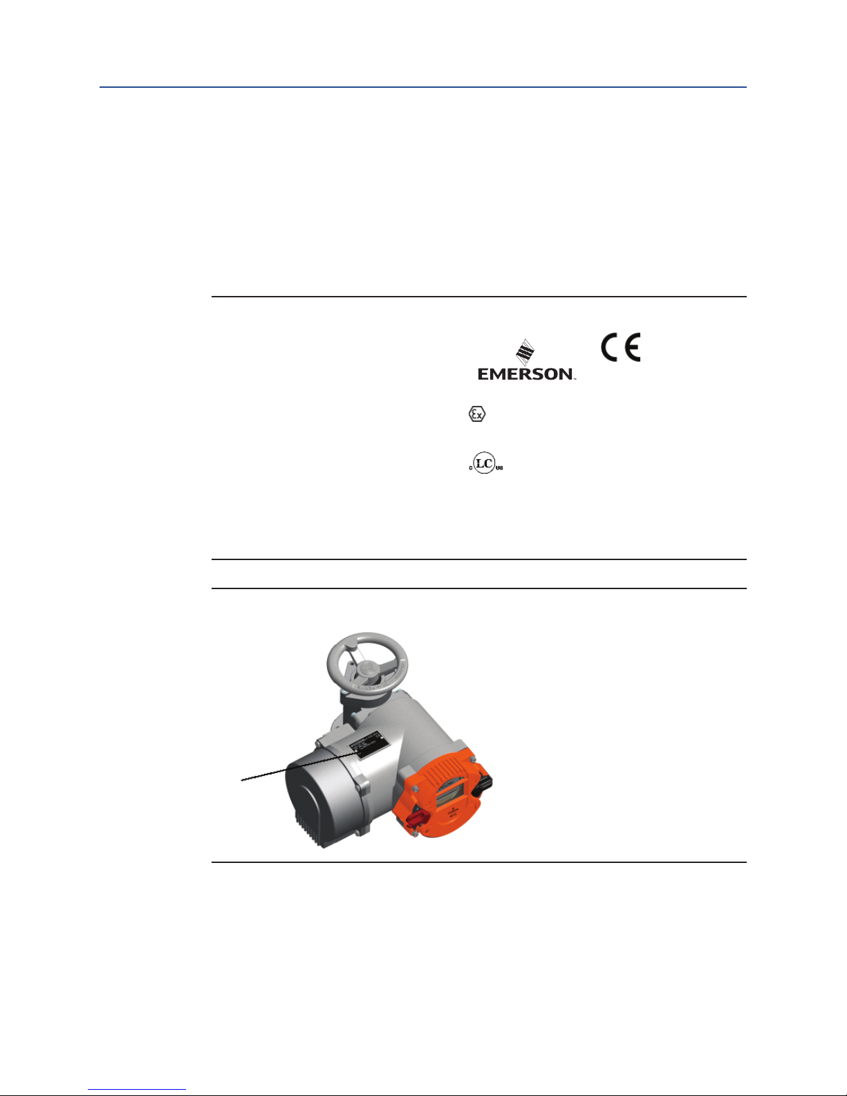
2.2 Serial Number and Type Label
Each actuator of the RTS Compact Linear CL series carries a serial number. The serial
number is a 10-digit number that begins with the year and that can be read from the type
label (see Figure 3) of the actuator (the type label is located next to the handwheel – see
Figure 4).
Using this serial number, Emerson can uniquely identify the actuator (type, size, design,
options, technical data and test report).
Figure 3 Bettis RTS Tag and Serial Number
Type:
CL-15A-1M0HE
No.:
18113E04275
Close:
Open:
75mm
1x115V-230V +/-10% AC/D
S2-15min
S4-1200c/h - 40%ED
19200 Northwest Fw
15,0kN
15,0kN
5,7-451sec
0,17-4,8mm/sec
I :
1,47A/230VAC
N
Tamb-40..+60°C
II 2 G Ex de IIC T4 Gb
IP68
Houston, TX 77065
TÜV-A16ATEX0007X
LC16.13198-1S
AEx de IIC T4 Gb
IECEx LC 17.0003X
Ex de IIC T4 Gb
Class 1 Div 1 & 2 Group D
User Instructions
MAN-02-04-60-0350-EN Rev. 3
1026
2018
180966/1
Figure 4 Label 1 - Type Label
1
2.3 Operating Mode
RTS Compact Linear CL actuators are suitable for open-loop control (S2 operating mode on/off duty) and closed-loop control (S9 operating mode - modulating duty) according to
EN 60034-1.
5
General
Page 11

User Instructions
MAN-02-04-60-0350-EN Rev. 3 February 2019
Section 2: General
2.4 Protection Class
RTS Compact Linear CL actuators come by default with IP 68 (EN 50629) protection.
CAUTION: PROTECTION CLASS AND CABLE GLANDS
The protection class specied on the type label is only effective when cable glands also provide the required protection class, the cover of the connection compartment is carefully
screwed and the mounting position (see Section 2.5) is observed.
We recommend metallic screwed cable glands with a metrical thread. Furthermore, cable
inlets not be needed must be closed with screw plugs. On explosion-proof actuators, cable
glands with protection class EEx e according EN60079-7 must be used. After removing
covers for assembly purposes or adjustment work, take special care upon reassembly so
that seals are not damaged and remain properly fastened. Improper assembly may lead to
water entrances and to failures of the actuator.
NOTE:
The cover of the control unit - the Operating unit - (see Figure 1) must not be opened.
Allow a certain sag in the connector cables before reaching the screwed cable glands so that
water can drip off from the connector cables without running to the screwed cable glands.
As a result, forces acting on the screwed cable glands are also reduced. (see Section 2.5)
2.5 Mounting Position
Generally, the installation position is irrelevant. However, based on practical experience, it
is advisable to consider the following for outdoors use or in splash zones:
• Mount actuators with cable inlet facing downwards
• Ensure that sufcient cable slack is available
General
6
Page 12

Section 2: General
February 2019
2.6 Direction of Rotation
Unless specically ordered otherwise, the standard direction is (see Figure 5 and Figure 6):
• Right turning (clockwise) = CLOSING
• Left turning (counter clockwise) = OPENING
Clockwise rotation of the actuator is given when the output shaft turns counter clockwise
when looking on the output shaft.
Figure 5 Clockwise = Close
User Instructions
MAN-02-04-60-0350-EN Rev. 3
Figure 6 Counterclockwise = Close
CAUTION: OBSERVE DIRECTION OF ROTATION
All specications in this operating manual refer to the standard direction of rotation.
7
General
Page 13

User Instructions
MAN-02-04-60-0350-EN Rev. 3 February 2019
Section 2: General
2.7 Protection Devices
2.7.1 Torque
RTS Compact Linear actuators provide a electronic torque monitoring.
The switch off torque can be modied in the menu of the controller for each
direction separately. By default, switch off torque is set to the ordered value. If no
torque was specied with the order, the actuator is supplied from the factory with
the maximum congurable torque.
For more information, (see Section 7.2).
2.7.2 Motor Temperature
All RTS Compact Linear CL actuators are normally equipped with motor winding
temperature sensors, which protect the motor against excessive winding
temperature.
The display will show the corresponding error upon exceeding the permissible
motor temperature (see Section 12.1).
2.7.3 Input fuse, thermal fuse
The frequency inverter is protected by an input fuse and the explosion-proof
version also has a thermal fuse. If one of these fuses releases, a serious defect
accours and the frequency inverter will be disconnected permanent from the
power supply. Then the frequency inverter must be changed.
2.8 Ambient Temperature
Unless otherwise specied upon ordering, the following operating temperatures apply:
• On/off duty (open-loop control) -25 to +60°C
• Modulating duty (closed-loop control) -25 to +60°C
• Explosion-proof version -20 to +40°C (acc. EN60079-0)
• Explosion-proof version with extended temperature range -40 to +60°C
CAUTION: OBSERVE OPERATING TEMPERATURE
The maximum operating temperature can also depend on further order-specic components.
Please refer to the technical data sheets to conrm the as-delivered product specications.
General
8
Page 14
Section 2: General
February 2019
2.9 Delivery Condition of the Actuators
For each actuator, an inspection report is generated upon nal inspection. In particular, this
comprises a full visual inspection, calibration of the torque measurement in connection
with an extensive run examination and a functional test of the micro controllers.
These inspections are conducted and documented according to the quality system and can
be made available if necessary. The basic setting of the end position must be performed
after assembly on the actuator.
CAUTION: OBSERVE COMMISSIONING INSTRUCTIONS
Commissioning instructions (see Section 5) must be strictly observed. During assembly
of the supplied valves at the factory, end postions are set and documented by attaching a
label (see Figure 7). During commissioning at the plant, these settings must be veried.
User Instructions
MAN-02-04-60-0350-EN Rev. 3
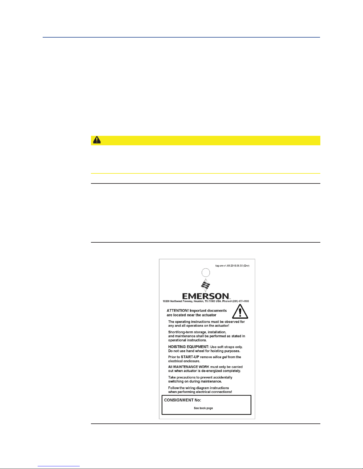
2.10 Information Notice (Tag)
Each actuator is provided with a bilingual tag containing key information, which is attached
to the handwheel after nal inspection. This tag also shows the internal commission
registration number (see Figure 7).
Figure 7 Tag
9
General
Page 15

User Instructions
MAN-02-04-60-0350-EN Rev. 3 February 2019
Section 3: Packaging, Transport and Storage
Section 3: Packaging, Transport and Storage
Depending on the order, actuators may be delivered packed or unpacked. Special
packaging requirements must be specied when ordering. Please use extreme care when
removing or repackaging equipment.
CAUTION: USE APPROPRIATE LIFTING EQUIPMENT
Use soft straps to hoist the equipment; do not attach straps to the handwheel.
If the actuator is mounted on a valve, attach the hoist to the valve and not to the actuator.
3.1 General
The connection compartment of RTS Compact Linear CL actuators contains 5g of factory
supplied silica gel.
CAUTION: REMOVE SILICA GEL
Please remove the silica gel before commissioning the actuator (see Section 5).
3.2 Storage
CAUTION: OBSERVE PROPER STORAGE
- Store actuators in well-ventilated, dry premises
- Protect against oor dampness by storing actuators on wooden grating, pallets,
mesh boxes or shelves
- Protect the actuators against dust and dirt with plastic foil
- Actuators must be protected against mechanical damage
- The storage temperature must be between -20°C bis +40°C
It is not necessary to open the controller of the actuator for servicing batteries or
similar operations.
Packaging, Transport and Storage
10
Page 16

Section 3: Packaging, Transport and Storage
February 2019
3.3 Long-term Storage
CAUTION: 6 MONTHS OF STORAGE
If you intend to store the actuator for over 6 months, also follow the instructions below:
- The silica gel in the connection compartment must be replaced after 6 months of
storage (from date of delivery)
- After replacing the silica gel, brush the connection cover seal with glycerine.
Then, carefully close the connection compartment again
- Coat screw heads and bare spots with neutral grease or long-term
corrosionprotection
- Renovate damaged paintwork arising from transport, improper storage,
or mechanical inuences
- For explosion-proof actuators, it is not allowed to extensively overpaint the actuator.
According to the standard, in order to avoid electrostatical charge, the maximal
thickness of the varnish is limited to 200 µm.
- Every 6 months all measures and precautions for long term storage must be
checked for effectiveness and corrosion protection and silica gel renewed
- Failure to follow the above instructions may lead to condensation which can damage
to the actuator
User Instructions
MAN-02-04-60-0350-EN Rev. 3
11
Packaging, Transport and Storage
Page 17

User Instructions
MAN-02-04-60-0350-EN Rev. 3 February 2019
Section 4: Installation Instructions
Section 4: Assembly and Disassembly of
Linear Units on Valves
In the following two subsections, the procedures for assembly and disassembly of linear
units on valves are explained step by step.
4.1 Security and Assembly Instructions
CAUTION
The device should be mounted and commissioned by qualied personnel. These are
individuals who are familiar and trained on the product line on how to operate and
assemble / disassemble the device.
Before assembling or disassembling the linear unit, the pipes have to be pressurized.
Only in the retracted state of the linear unit is an end stop available - if the maximum stroke
is exceeded in the extended state, the spindle moves out of its guidance! Do not move
against the end stop in electrical operation! The end limits of the actuator must be
set accordingly.
Never bring the valve cone with excessive force in the CLOSED position. This can damage
the high-quality sealing edges.
Installation Instructions
NOTE:
Installation work on any kind of actuator may only be performed by qualied personnel.
12
Page 18

Section 4: Installation Instructions
February 2019
4.2 Mechanical Connection
1. Check that the actuator ange, the linear unit anges and the valve ange match.
2. Thoroughly clean mounting surfaces and bare parts on actuator, linear unit
and valve.
3. Lightly grease the connections of the actuator, the linear unit and the valve.
4. Grease the spindle of the linear unit.
5. Move the valve cone in the CLOSED position.
6. Turn the spindle nut until the linear unit is in a central position.
7. Mount the linear unit on the valve and tighten the screws clockwise.
The coupling between the linear unit and the valve will be connected later.
8. Mount the actuator on the linear unit and tighten the screws clockwise.
9. Extend the spindle by rotating the handwheel until the coupling of the linear unit
and the valve t together.
10. Connect the coupling between linear unit and valve.
11. Use the handwheel to move the linear unit to a center position to prevent
accidental damage to the valve during startup.
User Instructions
MAN-02-04-60-0350-EN Rev. 3
NOTE:
For output type A (unbored threaded bushing), you must sufciently lubricate both needle
bearings in the output form after processing and cleaning the spindle nut.
For this purpose, use the optional Bettis RTS CL grease lubricant or a grease lubricant
according to our recommendation (see Section 14).
4.3 Disassembly
1. If the valve is fully closed, move the valve cone to about ten percent OPEN position
2. Loosen the screws between the output ange of the actuator and the linear unit
and dismount the actuator.
3. Open the spindle coupling between the linar unit and the valve.
4. Loosen the screws between the output ange of the linear unit and the valve
5. Dismount the linear unit from the valve.
13
Installation Instructions
Page 19
User Instructions
MAN-02-04-60-0350-EN Rev. 3 February 2019
Section 4: Installation Instructions
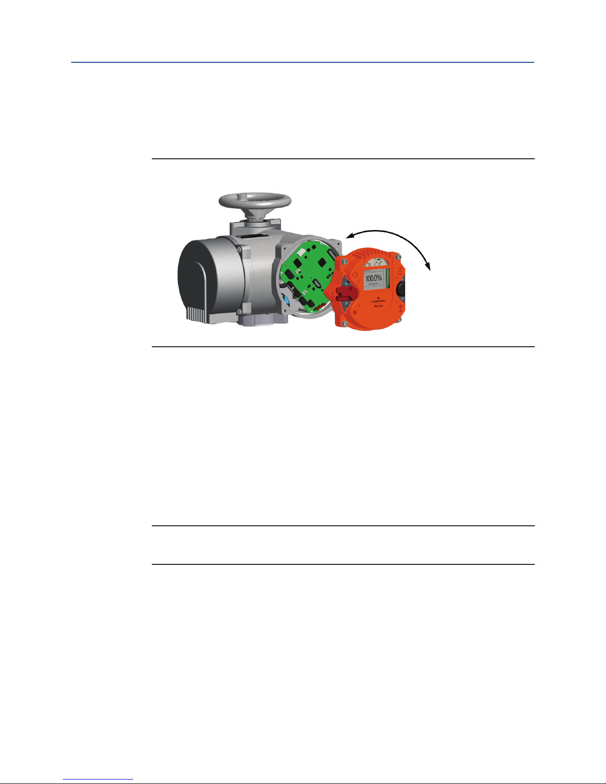
4.4 Mounting Postion of the Operating Unit
The mounting postion of the operating unit can be rotated in 90° steps.
Figure 8 Control System Mounting
-90°
+90°
+180°
• Disconnect the actuator and control system from the power supply.
• To prevent damage to the electronic components, both the control system and
the person have to be earthed.
• Unscrew the bolts for the interface surface and carefully remove the service cover.
• Turn service cover to new position and put back on.
— Ensure correct position of the O-ring
— Turn service cover by max. of 180°.
— Put service cover on carefully so that no cables get wedged in.
• Screw the bolts shut evenly in a crosswise sequence.
Important
Maximum torque: 5 Nm
Installation Instructions
14
Page 20

Section 4: Installation Instructions
February 2019
4.5 Electrical Connection
CAUTION: ELECTRICAL CONNECTIONS
Electrical connections may only be carried out by qualied personnel. Please observe
all relevant national security requirements, guidelines, and regulations. The equipment
should be de-energized before working on electrical connections. Furthermore, conrm
the absence of electrostatic discharges during the connection. First of all, connect the
ground screw.
The line and short circuit protection must be done on the system side.
The ability to unlock the actuator is to be provided for maintenance purposes.
For the dimensioning the rated current is to be used (see Technical Data).
Check whether the power supply (voltage, frequency) is consistent with the connection
data (see name plate - Figure 3)
The connection of electrical wiring must follow the circuit diagram. This can be found in
the appendix of the documentation. The circuit diagram can be ordered from Emerson by
specifying the serial number.
When using options, such as a Probus connection, the relevant guidelines must
be followed.
User Instructions
MAN-02-04-60-0350-EN Rev. 3
15
Installation Instructions
Page 21
User Instructions
MAN-02-04-60-0350-EN Rev. 3 February 2019
Section 4: Installation Instructions
4.5.1 Power Supply Connection
RTS Compact Linear CL actuators feature an integrated motor controller, i.e. only a
connection to the power supply is required. In non explosion-proof actuators, the
wiring uses a connector independent from control signals
(see Figure 9).
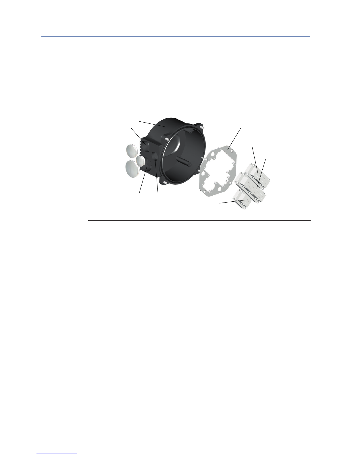
Figure 9 Enclosure Parts
8
1
2
3
4
7
6
5
Parts Overview:
1. Metric screw M32x1,5
2. M40x1,5, 3 - M25x1,5
3. M25x1,5
4. Plug insert Han6E (for power supply)
5. Plug insert Han24E (for control cables)
6. Connector for options
7. Connector Plate
8. Connecting Housing
Explosion-proof actuators or on special request the connection will be made via terminals
(see Figure 10).
Installation Instructions
16
Page 22
Section 4: Installation Instructions
February 2019
Figure 10 Bettis RTS Terminal Box
Terminal Box Overview:
1. Metric screw M40x1,5
2. 2 x M20x1,5
3. M25x1,5
4. Terminals for the power supply
5. Terminal for ground connection
6. Outside ground connection
Explosion-proof actuators or on special request the connection will be mady via terminals
(see Figure 10).
User Instructions
MAN-02-04-60-0350-EN Rev. 3
17
CAUTION: OBSERVE CORRECT PROCEDURE
If, during outdoor installation, commissioning is not carried out immediately after
electrical connection, the power supply must be connected at a minimum to achieve a
heating effect. In this case, the silica gel may remain in the connection compartment until
commissioning. (see Section 3.3)
Installation Instructions
Page 23

User Instructions
MAN-02-04-60-0350-EN Rev. 3 February 2019
Section 5: Commissioning
Section 5: Commisioning
Before commissioning, please ensure the actuator is correctly assembled and electrically
connected. (see Section 4,).
CAUTION: REMOVE SILICA GEL
Remove silica gel from the connection compartment.
5.1 General
CAUTION: RESET ELECTRIC END POSITIONS
During commissioning and after every disassembly of the actuator, the electric end positions (see Section 5.4) must be reset.
5.2 Manual Operation
The use of a differential gearbox in the handwheel assembly makes mechanical switching
unnecessary during manual operation.
CAUTION: DO NOT USE CHEATER BARS
Manual operation with mechanical or electromechanical equipment (such as: lever, drilling
machine, etc.) is NOT ALLOWED, as this may damage the product.
5.3 Mechanical Default Settings and Preparation
The use of linear sensors makes mechanical settings unnecessary.
CAUTION: ADJUST TORQUE BEFORE OPERATION
Before the motorised operation of the valve, it is essential to check and eventually adjust
torque settings.
5.4 End Limit Setting
A detailed description of the operation of the RTS Compact Linear CL controller can be
found in Section 6.3.
Commissioning
18
Page 24
Section 5: Commissioning
February 2019
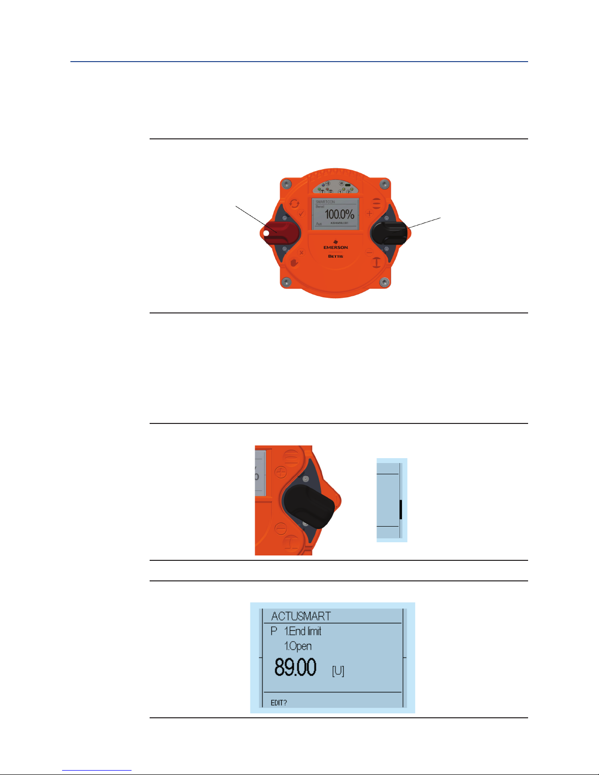
5.4.1 End limit OPEN
Step 1 - Set the selector switch and control switch to the centre position.
Figure 11 Switches in Center Position
User Instructions
MAN-02-04-60-0350-EN Rev. 3
1
2
Terminal Box Overview:
1. selector switch (red)
2. control switch (black)
Step 2 - Scroll through the menu with the control switch. Move the control switch towards
the rst menu item "P 1.1 End limit – Open".
Figure 12 Control Switch End Limit Open
Figure 13 Front Display for End Limit Open
19
Commissioning
Page 25
User Instructions
MAN-02-04-60-0350-EN Rev. 3 February 2019
Section 5: Commissioning
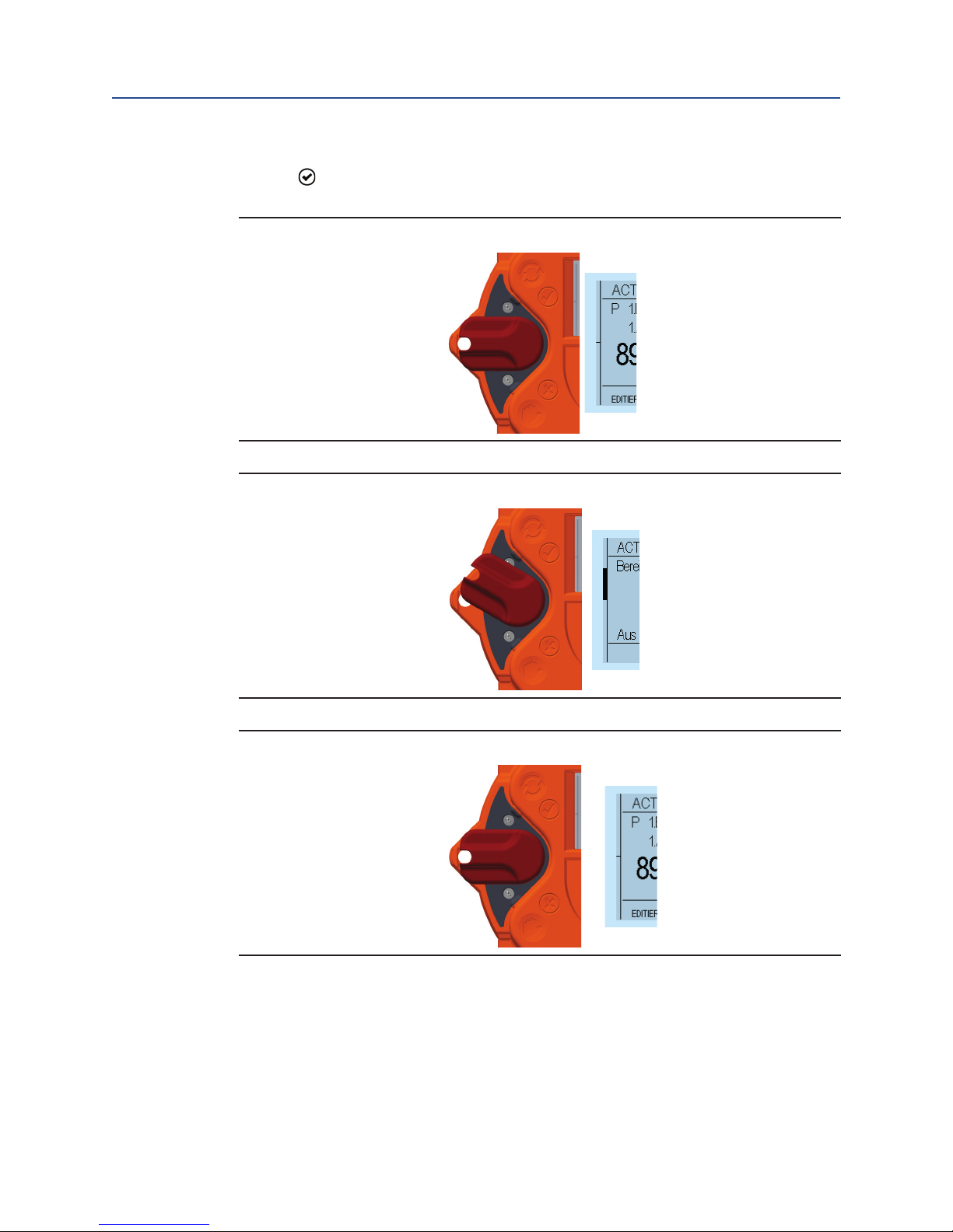
Step 3 - Afterwards, ip up the selector switch slightly and let it snap back to its neutral
position.
Figure 14 Selector Switch Setting (1)
Figure 15 Selector Switch Setting (2)
Figure 16 Selector Switch Setting (3)
Commissioning
20
Page 26
Section 5: Commissioning
February 2019
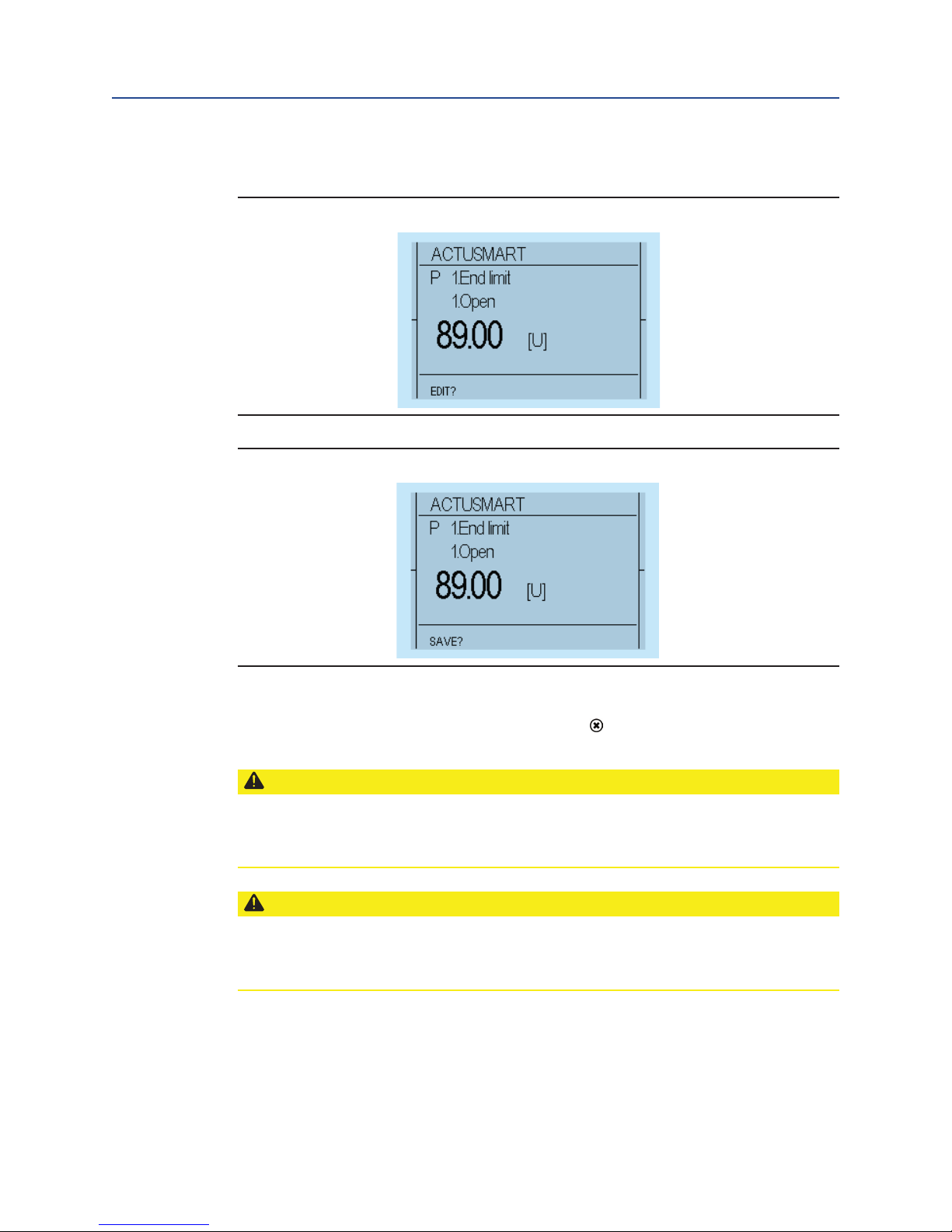
Step 4 - This changes the bottom line of the display from "EDIT?" to "SAVE?"
Figure 17 Edit and Save
Figure 18 Save Settings
User Instructions
MAN-02-04-60-0350-EN Rev. 3
Step 5 - Then, push down the selector switch until it snaps into place. In doing so, the
bottom right now on the display will show "TEACHIN" .
CAUTION: USE OPERATING SWITCH
Once the display shows "TEACHIN", use the operating switch (black switch) to start the
motorised operation of the actuator. In this mode, no travel-dependent switch off occurs in
the end position.
CAUTION: CHECK MAXIMUM PARAMETERIZED TORQUE
Please note that, during motor operation, only torque monitoring remains active, as travel
ad justment will happen subsequently. Therefore, please check beforehand whether the
maximum torque has been already parameterised
21
Commissioning
Page 27
User Instructions
MAN-02-04-60-0350-EN Rev. 3 February 2019
Section 5: Commissioning
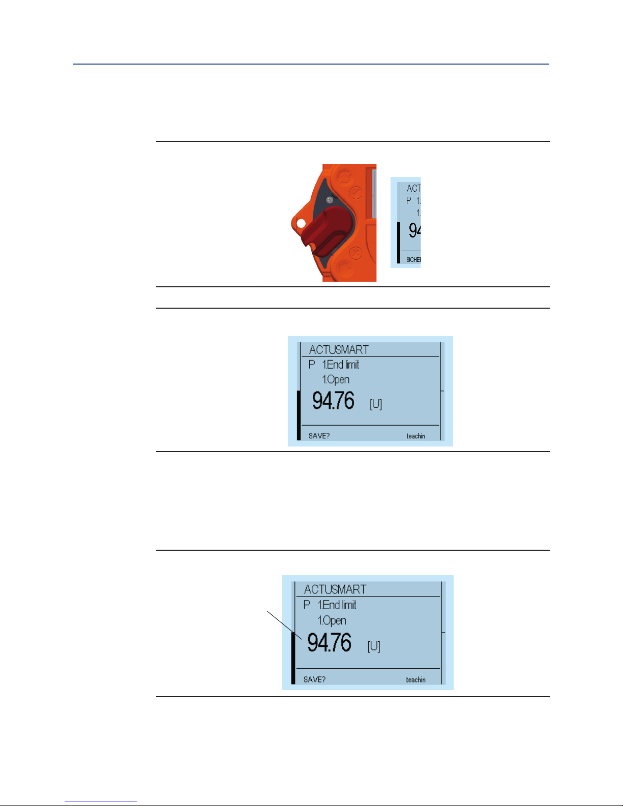
Step 6 - Absolute and relative values on the display will change continuously along with
position changes.
Figure 19 Position Change Selector Setting
Figure 20 Position Change Display
Step 7 - Manually move the actuator with the handwheel (see Section 2.1, or 2.6) or by
motor via the operating switch (black button) to the end position OPEN of the valve.
• Absolute value: Absolute value of the position feedback
• Relative value: the value to the other end postion
Figure 21 Absolute Value
1
Commissioning
22
Page 28

Section 5: Commissioning
February 2019
Display Overview:
1. Absolute value,
2. Relative value
Step 8 - When the desired end position OPEN of the valve is reached, move the selector
switch back to the middle position. Thus, the line "TEACHIN" disappears.
Figure 22 Selector for End Position (Save)
User Instructions
MAN-02-04-60-0350-EN Rev. 3
Figure 23 End Position Display
Step 9 - In order to conrm the end position (save), slightly ip up the selector switch
towards and let it snap back to its neutral position.
Figure 24 Selector Setting Save (1)
23
Commissioning
Page 29

User Instructions
MAN-02-04-60-0350-EN Rev. 3 February 2019
Section 5: Commissioning
Figure 25 Selector Setting Save (2)
Figure 26 Selector Setting Save (3)
Step 10 - This changes the bottom line of the display for "SAVE?" to "EDIT?" and the end
position is stored.
Figure 27 Selector Setting Display (1)
Commissioning
24
Page 30

Section 5: Commissioning
February 2019
Figure 28 Selector Setting Display (2)
5.4.2 End limit CLOSE
Use menu item "P 1.2 End limit - End limit CLOSE" as for End limit OPEN
5.5 Final Step
Following commissioning, check for proper sealing the covers to be closed and cable inlets.
(see Section 2.4) Check actuator for paint damage (by transport or installation) and repair
if necessary.
User Instructions
MAN-02-04-60-0350-EN Rev. 3
25
Commissioning
Page 31

User Instructions
MAN-02-04-60-0350-EN Rev. 3 February 2019
Section 6: Control Unit
Section 6: Control Unit
The controller is intended to monitor and control the actuator and provides the interface
between the operator, the control system and the actuator.
6.1 Operating Unit
Operation relies on two switches: the control switch and a padlock-protected selector
switch. Information visualization is provided by 4 integrated indicator lights, as well as the
graphic display. For better visibility, switch symbols ( , , , ) are on the cover.
Figure 29 Operating Unit Controls
4
1
Display Overview:
1. Selector switch
2. Control switch,
3. Graphic display,
4. LED display
The controller switches serve on the one hand for electric-motor operation of the actuator
and, on the other hand, to congure and view various menu items.
3
2
The controller cover may be wiped clean with a damp cloth.
The mounting position of the control unit can be turned in 90° steps (see Section 4.4).
Control Unit
26
Page 32

Section 6: Control Unit
February 2019
6.2 Display Elements
6.2.1 Graphic Display
The graphic display used in the controller allows text display in different languages.
Figure 30 Display (1)
User Instructions
MAN-02-04-60-0350-EN Rev. 3
During operation, the displays shows the position of the actuator as a percentage,
operation mode and status. When using the option "identication", a customer-specic
label is shown at the bottom of the display (e.g., PPS Number).
Figure 31 Display (2)
Display Overview:
1. Status
2. Operation mode
3. Position
27
Control Unit
Page 33

User Instructions
Section 6: Control Unit
MAN-02-04-60-0350-EN Rev. 3 February 2019
6.2.2 LED Display
To provide users with better status information, basic status data is displayed using
4-colour LEDs. As the device powers up, it undertakes a self-test whereby all 4 LEDs briey
lit up simultaneously.
Figure 32 LED Display
L3 L5 L4 L1 L2
Table 1. LED Colour Legend
Description Colour Lits up Flashes quickly Flashes slowly Does not light up
L1 Yellow
L2 Yellow
(1)
L3
(1)
L4
L5
Red OPEN
Green Closed
Blue
Red Infrared ON
No torque
error
Ready
(operational
readiness)
Bluetooth
enabled
Torque fault — —
Path error (no
operational
readiness!)
Moving to OPEN
position
Moving to
CLOSED position
Bluetooth data
transmission
Infrared data
transmission
—
Applies upon torque-
dependent opneing:
Occurs when the end
position OPEN is reached
but the cut-out torque has
not yet been reached
Applies upon torque-
dependent closing: Occurs
when the end position
CLOSED is reached but the
cut-out torque has not yet
been reached
Bluetooth ON, no data
transmission
Infrared ON
Error (no operational readiness)
motor temperature, supply
voltage absent, internal error
Actuator is not in the open
Actuator is not in the closed
Bluetooth/Infrared OFF
position.
position.
Control Unit
28
Page 34

Section 6: Control Unit
February 2019
6.3 Operation
The actuator is operated via the switches located on the controller (selection- and control
switch). All actuator settings can be entered with these switches. Furthermore, conguration
is also possible via the IR interface or the Bluetooth Interface (see Section 10). Flip the switch
up or down to regulate the parameter menu scrolling speed.
Figure 33 Neutral Position
User Instructions
MAN-02-04-60-0350-EN Rev. 3
Figure 34 Slight Switch Flip (It Will Move to the Next Parameter)
Figure 35 Halfway Switch Flip (Jump to the Next Parameter Category)
29
Control Unit
Page 35

User Instructions
MAN-02-04-60-0350-EN Rev. 3 February 2019
Section 6: Control Unit
Figure 36 Full Switch Flip (Jump to the End of the Menu)
6.3.1 Operation mode
Use the selector switch (red) to determine the various operating states of the
actuator. In each of these positions, it is possible to block the switch by means of a
padlock and thus protect the actuator against unauthorized access.
The selector switch has the following positions:
Table 2. Selector Positions
Position Function
OFF
Local
Remote
The actuator can be neither operated via the remote control nor via the control
switches of the controller.
It is possible to operate the actuator by motor via the control switch. Control via
the remote inputs may be possible with appropriate conguration (superimposed
control commands, emergency commans)
The actuator is ready to process control commands via input signals. The control
switch for the motor operation of the actuator is not enabled.
Besides dening the operational status, the selector switch is used in conguration mode
to conrm or cancel parameter inputs.
Control Unit
30
Page 36

Section 6: Control Unit
February 2019
Depending on the selector switch position, the control switch performs different functions:
Table 3. Control Switch Positions
Position Function
User Instructions
MAN-02-04-60-0350-EN Rev. 3
Selector switch
in the OFF
position:
Selector switch
in the REMOTE
position :
Selector switch
in the LOCAL
position :
The control switch is used to scroll up or down the menu according to internal
symbolism. From the neutral position towards you reach the status and history
data areas. Towards the symbols you reach the parameter menu. Here, the
selection switch either conrms or rejects the current input according to
associated symbolism.
The control switch gives you access to status, history data and parameter area.
With the control switch, the actuator can be operated by motor. You may also
operate the actuator in inching and self-hold mode. Switches are spring-loaded
to snap back automatically into their neutral position. (To conrm a control
command, the control switch must be pushed all the way into its mechanical
locking position.)
6.3.2 Configuration
In principle, all parameters are shown as numbers in the corresponding parameter
point. From the actuator menu, use the control switch to access different menu
points. The lower left corner of the display shows the "EDIT" option.
Figure 37 Configuration Display (1)
31
Control Unit
Page 37

User Instructions
MAN-02-04-60-0350-EN Rev. 3 February 2019
Section 6: Control Unit
Conrm the selector switch (with a slight ip towards , (see Figure 24, to Figure 28, ) to
change the selected parameter. To conrm this input readiness, the display changes from
"EDIT" to "SAVE".
Figure 38 Configuration Display (2)
Use the control switch towards to the characters to change the parameter. or
(see Figure 33 to Figure 36). After reaching the desired parameter value, conrm the value
with the selector switch (again, ip it slightly towards , (see Figure 24 to Figure 28,).
6.3.3 Configuration example
By way of example, we will change parameter P20.6 (wireless) from 0 (wireless off) to 2
(Bluetooth communication on). Thus, the Bluetooth connection is activated for a short
time and then deactivated again automatically:
Step 1 - The operating and control switch must be in the neutral position.
Figure 39 Selector Switch (1, Red); Control Switch (2, Black)
1
2
Control Unit
32
Page 38

Section 6: Control Unit
February 2019
Step 2 - Now, move the control switch down (towards ) until the menu item "P 20.6
Miscellaneous - Wireless" is displayed.
Figure 40 Control Switch Flipped Down
Figure 41 Display (1)
User Instructions
MAN-02-04-60-0350-EN Rev. 3
Step 3 - Afterwards, ip up slightly the selector switch (towards ) and let it snap back to its
neutral position.
Figure 42 Selector Switch in Neutral Position
33
Control Unit
Page 39

User Instructions
MAN-02-04-60-0350-EN Rev. 3 February 2019
Section 6: Control Unit
Figure 43 Selector Switch Flipped Up
Figure 44 Selector Switch in Neutral Position
Step 4 - This changes the bottom line of the display from "EDIT?" to "SAVE?".
Figure 45 Display (2)
Control Unit
34
Page 40

Section 6: Control Unit
February 2019
Figure 46 Display (3)
Step 5 - Flip up the control switch (toward ) to change the value from 0 (off) to 2 (Bluetooth).
Figure 47 Control Switch Flipped Up
User Instructions
MAN-02-04-60-0350-EN Rev. 3
Figure 48 Switch to One
35
Control Unit
Page 41

User Instructions
MAN-02-04-60-0350-EN Rev. 3 February 2019
Section 6: Control Unit
Step 6 - If the value changes to 1, conrm the selection by ipping halfway up the selector
switch (towards) and letting it snap back to its neutral position (see Figure 42 til Figure 46).
Figure 49 Selector Switch Flipped Halfway Up
Figure 50 Display After Confirming Selection
Step 7 - This changes the bottom line of the display from "SAVE?" to "EDIT?" and the
parameter is stored.
6.3.4 "TEACHIN“
Furthermore, certain parameters (end positions, intermediate positions), can be
set using "TEACHIN". Thus, their conguration is greatly simplied.
After selecting the appropriate menu item (for example: End position) and
chanching the the input type from "EDIT?" to "SAVE?", move the selector switch
(red) to "manual mode" and lock it into place. As you do so, the display will show
the message "TEACHIN" and the current position value will be applied continuously
to the parameter value. In this mode, further to manual operation by hand wheel,
the actuator can be motor-driven with the control switch to the desired position.
(see Section 5.4.1)
Control Unit
36
Page 42

Section 6: Control Unit
February 2019
Figure 51 'Teachin' on Display
Please note that, during motor operation, only torque monitoring remains active, as travel
adjustment will happen subsequently. Therefore, please check beforehand whether the
maximum torque has been already set.
User Instructions
MAN-02-04-60-0350-EN Rev. 3
CAUTION: MAXIMUM TORQUE MUST BE ALREADY SET
After reaching the desired, to-be-dened position, move the selector switch back to the
neutral position. Finally, the param- eter value must still be saved by ipping the selector
switch halfway up and letting it snap back to the neutral position (see Figure 42 to Figure 46).
37
Control Unit
Page 43

User Instructions
MAN-02-04-60-0350-EN Rev. 3 February 2019
Section 7: Parameter Menu
Section 7: Parameter Menu
For each parameter group, you can nd a description tabular overview of the menu items
and possible congurations. The parameter list below also includes all possible options
per menu item. Please note that some of the menu items listed and described may not be
delivered with your conguration.
7.1 Parameter Group: End Limit
These parameters are used to congure the end position and switch off behavior of the
actuator. In this regards, it is important to ensure that the basic mechanical conguration
described in Section 5.4 has already been made.
CAUTION: SET CORRECT PARAMETERS
Ensure that these parameters are set during commissioning before operating the actuator.
In addition, the settings in the "Torque" menu (see Section 7.2) must be compared with the
permissible values of the valve and corrected as appropriate)
CAUTION: NOTE OPEN/CLOSE VALUES
Generally, 100% stands for fully open and 0% for fully closed. Please note that these values
cannot be changed.
Parameter Menu
38
Page 44

Section 7: Parameter Menu
February 2019
Table 4. End Limit Parameter Group
User Instructions
MAN-02-04-60-0350-EN Rev. 3
Menu
Item
P1.1 End limit Open
P1.2
End limit Close
Sub
Menu
Item
Poss. Setting Notes / Comments
TEACHIN;
0 - 100U
TEACHIN;
0 - 100U
by travel (0)
The parameter value can be set using TEACHIN. With a known
travel, the second end position can be entered after setting
1)
the rst end position
The parameter value can be set using TEACHIN. With a known
travel, the second end position can be entered after setting
1)
the rst end position
The actuator uses end-position signals to switch off and
report the end position
The actuator signals the end position or stops the motor only
by torque (1)
after reaching the specied torque with the proviso that it
has reached the end position. If the end position signal is not
reached, the actuator reports an error
Like torque, but in the end position range, this is also
P1.3 End limit
Switch off
Open
by torque1 (2)
extended when the positioning command is released,
until the torque is reached
Like torque1, however, an actuating command is
by torque2 (3)
automatically generated additionally in the end position
range so that the end position in the end position range is
approached even without a positioning command
Like travel, however, the actuator still continues to drive
by travel1 (4)
the set Overrun time after reaching the end position,
even when the positioning command is released. Only
relevant if Overrun time (P1.10, P1.11) is greater than 0
by travel (0)
The actuator uses end-position signals to switch off and
report the end position
The actuator signals the end position or stops the motor only
after reaching the specied torque with the proviso that it
has reached the end position. If the end position signal is not
reached, the actuator reports an error
P1.4 End limit
Switch off
Close
by torque (1)
by torque1 (2) see P1.3
by torque2 (3) see P1.3
by travel1 (4) see P1.3
right (0) Actuator is designed for clockwise = closing
left (1)
0
1
Close=green
(0)
Close=red (1)
Reverse direction of rotation! Counterclockwise = closing. The
crossing of all signals and commands is per formed by the controller
No function at RTS Compact Linear CL series
Denition of the LED colour of the CLOSED or OPEN
end postion signalization
P1.5 End limit
P1.6 End limit
P1.7 End limit
Closing
direction
Rot. sense
pos.
LED
function
Hysteresis range for end position signals: Example: End position
P1.8 End limit
End limit
hyst
0,1 - 10,0%
hysteresis 1% means, that the End position OFF is reached when
closing 0%, and will leave it when opening only at 1%, i.e., a reclosing can only take place after leaving this hysteresis
P1.9 End limit Ramp 0.1 - 100% When approaching the end position, the speed is reduced
End position range for torque (P1.3, P1.4). Permissible
P1.10 End limit Range 0 - 100%
range in which the torque is to be achieved. If the
actuator comes to the end of the end position range, the
motor shuts off even if the torque has not been reached
P1.11 End limit
P1.12 End limit
1)
representative for CL03
Overrun
Open
Overrun
Close
0 - 60 s
0 - 60 s
Switch-off delay after reaching the end position see
travel1 (P1.3, P1.4)
Switch-off delay after reaching the end position travel1
(P1.3, P1.4)
39
Parameter Menu
Page 45

User Instructions
MAN-02-04-60-0350-EN Rev. 3 February 2019
Section 7: Parameter Menu
CAUTION: NOTE TRAVEL LIMITS
When installing the actuator on an gear or a thrust unit, please take into account the limits
and factors of the gear / thrust unit at parametrization.
CAUTION: SET LIMITS CORRECTLY
When using end limit switch off by torque, the end position limit must be set before
reaching the torque limit. Accordingly, the actuator will only signal the nal end position
if the congured torque and the associated end position are reached. If the end position is
not reached, a torque error is reported (see Section 6.2.2)
7.2 Parameter Group: Torque
If no torque was specied with the order, the actuator is supplied from the factory with the
maximum congurable torque.
Table 5. Torque Parameter Group
Menu Item
P2.1 Torque Open 8 - 32Nm
P2.2
Torque Close 8 - 32Nm2)As P2.1 but in CLOSED direction
P2.3 Torque Torque limit 8 - 32Nm
P2.4 Torque Latching {Off (0)} Unassigned in RTS Compact Linear CL series
P2.7 Torque Hysteresis {0: 50%} Unassigned in RTS Compact Linear CL series
2)
representative for CL03
Sub Menu
Item
Poss.
Setting
Notes / Comments
switch off torque in OPEN direction CAUTION: The range
2)
can be restricted via the menu item P2.3
Torque to protect the valve, the transmission or the
thrust unit.
2)
This value limits the setting of the Parameters P2.1 and P2.2
and to prevent an erroneous increase above the allowed
value of these two parameters.
CAUTION: NOTE GEAR AND THRUST UNITS
When installing the actuator on an additional gear, please take into account the
corresponding values of the gear / thrust unit as you enter the actuator parameters.
To achieve an effective output torque (incl. gear) / output power (including thrust unit)
ratio, the factor gear/thrust unit must be considered.
Parameter Menu
40
Page 46

Section 7: Parameter Menu
February 2019
7.3 Parameter Group: Speed
Table 6. Speed Parameter Group
User Instructions
MAN-02-04-60-0350-EN Rev. 3
Menu item
P4.1 Speed Local Open
P4.2
Speed Local Close
P4.3 Speed Remote Open
P4.4 Speed Remote Close
P4.5 Speed
P4.6 Speed
P4.7 Speed
P4.8 Speed Minimum
Sub Menu
item
Emergency
Open
Emergency
Close
Torquedependent.
Poss.
Setting
2,5 72,2min
2,5 72,2min
2,5 72,2min
2,5 72,2min
2,5 72,2min
2,5 72,2min
2,5 72,2min
2,5 72,2min
Notes / Comments
2)
Output speed for local operation in direction OPEN
−1
As P4.1 but in direction CLOSE
−1
Output speed for remote operation in direction OPEN
−1
As P4.3 but in direction CLOSE
−1
Output speed for emergency operation in direction OPEN
−1
As P4.5 but in direction CLOSE
−1
seal-tight speed. Speed at which the actuator runs near
the end position at torque-dependent switch off
−1
(see P1.3 u. P1.4)
Minimum speed
−1
CAUTION: NOTE MAXIMUM SPEED LIMITS
the max. speed for the 24VDC actuator version is reduced to 20min
−1
7.4 Parameter Group: Ramp (option)
The start ramp can be set separately for each operation mode. Thus, a 100% start ramp
means that the motor attains its maximum speed in about a second. Higher speeds
(see Section 7.3) lead to shorter runtimes. If the ramp is set below 100%, the starting time
increases in an inversely proportional fashion.
Table 7. Ramp Parameter Group
Menu Item Sub Menu Item
P5.1 Ramp Local 5 - 100% Start ramp for local operation
P5.2 Ramp Remote 5 - 100% Start ramp for remote operation
P5.3 Ramp Emergency 5 - 100% Start ramp for emergency operation
Poss.
Setting
Notes / Comments
41
Parameter Menu
Page 47

User Instructions
MAN-02-04-60-0350-EN Rev. 3 February 2019
Section 7: Parameter Menu
7.5 Parameter Group: Control
Table 8. Control Parameter Group
Menu Item
P6.2 Control Ready delay 0 - 10 sec. Drop-out delay for the ready signal (Binary outputs)
P6.53)Control 24V output
P6.6 Control Min. impuls
3)
since rmware 1.303
Sub Menu
Item
Poss.
Setting
0
{1} 24V auxiliary output is activated (section 16.5)
0.1 - 2.0
sec
Notes / Comments
24V auxiliary output is deactivated (section 16.5)
The function of the auxiliary input is still activated
Minimum switch-on time of the motor
7.6 Parameter Group: Password
The actuator control can be password-protected to prevent access at different levels. It is
possible to prevent entry by unauthorized personnel or to entirely lock motor operation.
Default password is set to "000" and thus deactivated.
You can use both numbers and capital letters in your password. After entering a password,
password protection is acti- vated. To remove password protection, enter an empty
password (000).
When accessing a password-protected parameter, the user is automatically prompted for
its introduction. Only after cor- rectly entering the password, it is possible to change the
corresponding parameters.
Parameter Menu
Table 9. Password Parameter Group
Menu Item
P7.1 Password Reading PWD 3-digit
P7.2 Password Writing PWD 3-digit
P7.3 Password
Sub Menu
Item
Bluetooth
PWD
Poss.
Setting
15-digit
Notes / Comments
Status display and history data are still viewable; access
to the parameter menu is locked until this password is
introduced. Parameter menu scrolling is only enabled
after entering the password. Electric motor operation is
unlocked.
Status display, history data and parameter menu can be
viewed. However, parameters become read-only.
Password for the Bluetooth connection, empty password
deactivates the password request.
42
Page 48

Section 7: Parameter Menu
February 2019
7.7 Parameter Group: Position
In addition to OPEN and CLOSED end positions, you may dene intermediate positions.
These can be used as feedback signals for the binary outputs or as target value for x
position approach.
CAUTION: CHANGING END POSITIONS
If you change the end positions (see Section 7.1, intermediate positions are retained
percentage-wise, i.e., the absolute positions of the intermediate positions change.
Table 10. Position Parameter Group
User Instructions
MAN-02-04-60-0350-EN Rev. 3
Menu Item
P8.1 Position
P8.2 Position
P8.3 Position
P8.4 Position
P8.5 Position
P8.6 Position Hysteresis 0,1 - 10,0%
Sub Menu
Item
Intermed.
pos.1
Intermed.
pos.2
Intermed.
pos.3
Intermed.
pos.4
Emerg.
position
Poss.
Setting
TEACHIN
0 - 100%
TEACHIN
0 - 100%
TEACHIN
0 - 100%
TEACHIN
0 - 100%
TEACHIN
0 - 100%
Notes / Comments
Position value of intermediate position 1
see above
see above
see above
Position value of the emergency position
Hysteresis range of intermediate positions. Within this
hysteresis, no repositioning occurs upon reaching the
intermediate positions (option: x position approach).
Furthermore, the output functions for position =
intermediate position are active within this range
(see P10.1)
7.8 Parameter Group: Binary Inputs
The controller is equipped with 5 freely congurable binary inputs. Please nd further
information on technical data of the binary inputs in Section 16.2. Binary inputs are also
effective during actuator control via Probus (option).
Default binary inputs are as follows:
• Input 1: OPEN
• Input 2: CLOSED
• Input 3: STOP
• Input 4: EMERGENCY OPEN
• Input 5: EMERGENCY Closed
43
Parameter Menu
Page 49

User Instructions
MAN-02-04-60-0350-EN Rev. 3 February 2019
Section 7: Parameter Menu
Table 11. Binary Inputs Parameter Group (1)
P9.1
Menu
Item
Binary
Input
Sub Menu
Item
Input 1
Poss. Setting Notes / Comments
0:no function This input has no function
1: Open
2: Closed
3: Stop
4: Open Self-hold
5: Closed Self hold Self-hold for CLOSED, see OPEN SELF-HOLD
6: Emergency
Open
7: Emergency
Closed
8: Release
9: Open/Closed
10: Close/Open
11: Positioner Release of the postioner
12: Open inv. As open but active low
13: Close inv. As CLOSED but active low
14: Stop inv. As STOP but active low
15: Open
Self-Hold inv.
16: Closed
Self-Hold inv.
17: EmergencyOpen inv.
18: EmergencyClosed inv.
19: Block
20: Contoller lock Positioner lock
OPEN command in REMOTE mode (selector switch in
position REMOTE).
CLOSED command in REMOTE mode (selector switch in
position REMOTE).
STOP command in REMOTE mode (selector switch in
position REMOTE).
Self-hold for OPEN, i.e., a short pulse is sufcient and the
actuator moves then into the end position. Use the STOP
command to stop the actuator.
Superimposed run command; run the actuator in direction
OPEN regardless of whether the selection switch is set to
REMOTE or LOCAL operation
Superimposed run command; run the actuator in direction
CLOSED regardless of whether the selection switch is set to
REMOTE or LOCAL
The actuator may be operated only with a switched signal.
Both in local and remote operation
The actuator moves towards OPEN if input is active and
towards CLOSED otherwise
The actuator moves towards CLOSED if input is active and
towards OPEN otherwise
As Open Self-Hold but active low
As Closed Self-Hold but active low
As Emergency-Open but active low
As Emergency-Closed but active low
With activated (switched) signal, the actuator is locked for
operation also in local mode
Parameter Menu
21: Release Local The actuator may be operated only with a switched signal.
22: Block Local As Release Local but active low
Trigger lock OPEN (in LOCAL and REMOTE mode).
23: Lock Open
Actuator moves with the highest priority to OPEN;
command continues internally active after reaching the
end position OPEN. Dropping only with LOCK OFF, Supply
OFF or operating mode OFF.
44
Page 50

Section 7: Parameter Menu
February 2019
Table 12. Binary Inputs Parameter Group (2)
User Instructions
MAN-02-04-60-0350-EN Rev. 3
Menu
Item
P9.1
Binary
Input
P9.2 Input 2 see Input 1 --P9.3 Input 3 see Input 1 --P9.4 Input 4 see Input 1 --P9.5 Input 5 see Input 1 ---
Sub Menu
Item
Input 1
Poss. Setting Notes / Comments
Trigger lock CLOSED (in LOCAL and REMOTE mode).
24: Lock Closed
25: Lock Off Drop the lock
26: Failsafe
27: Failsafe inv. As Failsafe but active low
28: Lock Open inv. As Lock Open but active low
29: Lock Closed
inv.
30: Lock Off inv. As Lock Off but active low
31: Intermediate
position1
32: Intermediate
position2
33: Intermediate
position3
34: Intermediate
position4
35: Emergency
position
36: Intermediate
position1 inv.
37: Intermediate
position2 inv.
38: Intermediate
position3 inv.
39: Intermediate
position4 inv.
40: Emergency
position inv.
41: Travel Open
42: Travel Close
43: Travel Open inv.
44: Travel Close inv.
45: Failsafe lock
46: Failsafe lock inv.
Actuator moves with the highest priority to CLOSED;
command continues internally active after reaching the
end position CLOSED. Dropping only with LOCK OFF,
Supply OFF or operating mode OFF.
Trigger the failsafe function in all operating modes (only
functional in failsafe actuators).
As Lock Closed but active low
Approach intermediate position 1 (P8.1) in REMOTE
mode (x position approach). There is no repositioning
upon reaching the intermediate position within the
hysteresis (see P8.6) Higher priority than intermediate
position 2, 3 and 4
As intermediate position 1 but with higher priority than
intermediate positions 3 and 4
As intermediate position 1 but with higher priority than
intermediate position 4
As intermediate position 1 but with lowest priority
Approach emergency position (P 8.5). As intermediate
position 1 but with higher priority than intermediate
positions 1, 2
As Intermediate position 1 but active low
As Intermediate position 2 but active low
As Intermediate position 3 but active low
As Intermediate position 4 but active low
As Emergency position but active low
45
Parameter Menu
Page 51

User Instructions
MAN-02-04-60-0350-EN Rev. 3 February 2019
Section 7: Parameter Menu
7.9 Parameter Group: Binary Outputs
The controller is equipped with 8 freely congurable binary outputs. Please nd further
information on technical data of the binary outputs in Section 16.1. Provided with external
supply, binary outputs are optically isolated from the rest of the controller.
Default binary outputs are as follows:
• Output 1: Ready
• Output 2: End position OPEN
• Output 3: End position CLOSED
• Output 4: Run OPEN
• Output 5: Run CLOSED
• Output 6: Torque
• Output 7: LOCAL
• Output 8: REMOTE
Table 13. Binary Outputs Parameter Group (1)
P10.1
Menu
Item
Binary
Output
Sub Menu
Item
Output 1
Poss. Setting Notes / Comments
0: User dened Optional
1: Ready Actuator is ready
2: Fault General fault; actuator is not ready
3: Open Actuator is in open position
4: Closed Actuator is in closed position
5: Running Open Actuators runs in direction Open
6: Running
Closed
7: Runing Actuator is running in either Open or Closed
8: Torque Open
9: Torque Closed
10: Torque
11: Travel Open The Open end postion has been reached
12: Travel Closed The Closed end postiion has been reached
13: Pos. > Int.1 Position > Intermediate position 1
14: Pos. < Int.1 Position < Intermediate position 1
15: Pos. > Int.2 Position > Intermediate position 2
16: Pos. < Int.2 Position < Intermediate position 2
17: Pos. > Int.3 Position > Intermediate position 3
18: Pos. < Int.3 Position < Intermediate position 3
19: Pos. > Int.4 Position > Intermediate position 4
20: Pos. < Int.4 Position < Intermediate position 4
21: Local Local oerating mode (selector switch in position)
Actuators runs in direction Closed
Switch off torque was reached in Open directionactuator has been switched off
Switch off torque was reached in Closed directionactuator has been switched off
Switch off torque was reached in either Closed or Open
direction
Parameter Menu
46
Page 52

Section 7: Parameter Menu
February 2019
Table 14. Binary Outputs Parameter Group (2)
Binary
P10.1
Output
Menu
Item
Sub Menu
Item
Output 1
User Instructions
MAN-02-04-60-0350-EN Rev. 3
Poss. Setting Notes / Comments
22: Remote
23: Off Off operating mode (selector switch in the Off position)
24: No function No function
25: Motor error The motor temperature sensor has reported an error
26: Always Signal is always on
27: Never Signal is always off
28: Binary Input 1 Forwarding of binary input to output
29: Binary Input 2 Forwarding of binary input to output
30: Binary Input 3 Forwarding of binary input to output
31: Binary Input 4 Forwarding of binary input to output
32: Binary Input 5 Forwarding of binary input to output
33: Torque Open ma.
34: Torque Closed ma.
35: Ready Remote Ready and Remote operating mode
36: Ready Local Ready and Local operating mode
37: Ready
Local/remote
38: Lock Open
39: Lock Closed
40: Failsafe OK1 Failsafe OK (only for failsafe actuators)
41: Failsafe OK2 Failsafe OK and Ready (only for failsafe actuators)
42: Failsafe OK3
43: Lock Lock Open or Lock Closed is enabled.
Remote operating mode (selector switch in position
Remote)
As Torque OPEN although it will supress (mask) this
signal in the end position upon torque-dependent
switch off.
As Torque CLOSED although it will supress (mask) this
signal in the end position upon torque-dependent
switch off.
Ready and Local or Remote mode
Lock OPEN is enabled. OPEN command is internally
queued with the highest priority and will not be
dropped even in the end position
Lock CLOSED is enabled. CLOSED command is internally
queued with the highest priority and will not be
dropped even in the end position
Failsafe OK,Ready and Remote
(only for failsafe actuators)
47
44: Ready/Torque OK Actuator is ready and no torque switch off
45: Ready/Remote/
Torque OK
46: Pos.=Int1
Actuator is ready for operation in REMOTE mode and no
torque switch off
Position = Intermediate position 1. The width of the
interval is set with the parameter P8.6
Parameter Menu
Page 53

User Instructions
MAN-02-04-60-0350-EN Rev. 3 February 2019
Section 7: Parameter Menu
Table 15. Binary Outputs Parameter Group (3)
Menu
Item
P10.1
Binary
Output
4-5
P10.2
P10.3 Output 2 see Output 1 --P10.4 Output 2 Konf. see Output 1 conf. --P10.5 Output 3 see Output 1 --P10.6 Output 3 Konf. see Output 1 conf. --P10.7 Output 4 see Output 1 --P10.8 Output 4 Konf. see Output 1 conf. --P10.9 Output 5 see Output 1 --P10.10 Output 5 Konf. see Output 1 conf. --P10.11 Output 6 see Output 1 --P10.12 Output 6 Konf. see Output 1 conf. --P10.13 Output 7 see Output 1 --P10.14 Output 7 Konf. see Output 1 conf. --P10.15 Output 8 see Output 1 --P10.16 Output 8 Konf. see Output 1 conf. ---
Sub Menu
Item
Output 1
Output
conf. 1
Poss. Setting Notes / Comments
47: Pos.=Int2
48: Pos.=Int3
49: Pos.=Int4
50:
Pos.=EmergPos
51: Bus Bit 1
52: Bus Bit 2
53: Bus Bit 3
54: Bus Bit 4
55: Bus Bit 5
56: Bus Bit 6
57: Bus Bit 7
58: Bus Bit 8
59: Virtual 1
60: Virtual 2
61: Virtual 3
62: Virtual 4
63: Line voltage OK Supply voltage for the motor is OK
64: Control
voltage OK
65: Oil
pressure OK
66: Oil level OK The oil level is OK
67: Pump OK
normal
inverted
norm. ashing
inv. ashing
Position = Intermediate position 2. The width of the
interval is set with the parameter P8.6
Position = Intermediate position 3. The width of the
interval is set with the parameter P8.6
Position = Intermediate position 4.The width of the
interval is set with the parameter P8.6
Position = emergency position. The width of the interval
is set with the parameter P8.6
In existing bus interface (hardware option) the output is
set according to the selected bit bus.
Congurable output function
The auxiliary voltage for the SMARTCON control is OK.
This function is only available if the auxiliary voltage
output is not switched on (P6.5 to 0)
The oil pressure is higher than the minimum pressure (P6.10)
The temperature sensor in the pump motor and the
external motor protection have not tripped
Output 1 is set to normal, i.e. if the condition in point
P10.1 is met, Output 1 is set to HIGH (active HIGH)
if the condition in point P10.1 is met, Output 1 is set to
LOW (active LOW)
if the condition in point P10.1 is met, Output 1 starts
blinking (active HIGH)
if the condition in point P10.1 is not met, Output 1 starts
blinking (otherwise it is set to HIGH)
4)
4)
Parameter Menu
from Firmware 1.323
48
Page 54

Section 7: Parameter Menu
February 2019
User Instructions
MAN-02-04-60-0350-EN Rev. 3
CAUTION: NOTE SET TORQUE AND POSITION
When using the point torque-dependent OPEN or torque-dependent CLOSED (see Section
7.1, Menu P1.3 u. P1.4) the actuator will only be open or closed when the set torque and
the associated end position is reached. If the end position is not reached, a torque error is
reported (see Section 6.2.2)
7.10 Parameter Group: Position Output (option)
Position output is used to indicate the current position of the actuator using 0/4-20 mA; it
can retrotted using software code.
If this option is not enabled, the menu point shows the message "inactive".
No adjustment to the end positions or the travel is required. Adjustment is automatically
performed during the conguration of travel limit positions (see Section 7.1)
No further settings are necessary for torque-dependent switch off, because the controller
exclusively uses travel limit posi- tions for the calculation. Regardless of whether this is
dened by the torque or the travel limit positions.
The factory default setting is:
4mA at 0% position 20mA at 100% position
Table 16. Position Output Parameter Group (1)
Menu item
P11.1 PositionOutput Function
Sub Menu
Item
Poss.
Setting
0: off mA output disabled
1: Position mA output corresponds to the actual position value
2: Pos.
Valvechar
3: Torque 1
4: Torqe 2
5: Torque 3
6: Torque 4
Notes / Comments
mA output corresponds to the actual position value
taking into account the valve characteristic.
mA output corresponds to the actual torque value
torque = 100% Close: mAoutput = start
torque = 0%: mAoutput = center
torque = 100% Open: mAoutput = end
mAoutput corresponds to the actual torque value
torque = 100% Close: mAoutput = end
torque = 0%: mAoutput = start
torque = 100% Open: mAoutput = end
mAoutput corresponds to the actual torque value
torque = 150% Close: mAoutput = start
torque = 0%: mAoutput = center
torque = 150% Open: mAoutput = end
mAoutput corresponds to the actual torque value
torque = 150% Close: mAoutput = end
torque = 0%: mAoutput = start
torque = 150% Open: mAoutput = end
49
Parameter Menu
Page 55

User Instructions
MAN-02-04-60-0350-EN Rev. 3 February 2019
Section 7: Parameter Menu
Table 17. Position Output Parameter Group (2)
Menu item
P11.2 Position Output Start (at 0%)
P11.3 Position Output End (at 100%)
P11.4 Position Output Calib. 20mA
P11.5 Analog Output Function 2
P11.6 Analog Output Start (at 0%) see Start
P11.7 Analog Output End (at 100%) see End
P11.8 Analog Output Calib. 20mA Calib. 20mA
Sub Menu
Item
Poss.
Setting
0 - 20,5
mA {4mA}
0 - 20,5 mA
{20mA}
-10% +10%
see
Function 1
Notes / Comments
mA value for the Closed (0%) position
mA-value for the On (100%) position
Calibrating the output position during the setting of
this parameter will output a 20mA (100%) signal. Use
this parameter to calibrate accurately the 20mA output
signal. (e.g., if you measure 19.8 mA at the output, just
add 1% (0.2 mA. . . 1% of 20mA) to the displayed value)
Parameter Menu
50
Page 56

Section 7: Parameter Menu
February 2019
7.11 Parameter Group: Step Mode
Step mode operation can be used to extend the operating time in certain ranges or for the
whole travel; it is available in local, remote and emergency mode.
Step mode operation can be activated individually for the directions OPEN and CLOSED.
Cycle start, cycle end, cycle duration and interval time can be set separately for both
directions. (see capter Figure 52).
Table 18. Step Mode Parameter Group
User Instructions
MAN-02-04-60-0350-EN Rev. 3
P12.1
P12.2
P12.3
P12.4
P12.5
P12.6
P12.7
P12.8
P12.9
P12.10
P12.11
Menu Item
Step mode
function
Step mode
function
Step mode
function
Step mode
function
Step mode
function
Step mode
function
Step mode
function
Step mode
function
Step mode
function
Step mode
function
Step mode
function
Sub Menu
Item
Mode
Start Open 0 - 100%
End Open 0 - 100%
Runtime Open 0,1 - 60 Runtime in OPEN direction
Pause time
Open
Start Closed 0 - 100%
End Closed 0 - 100%
Run time
Closed
Pause time 0,2 - 60 Pause time in Closed direction
Timebase
Speed
adaption
Poss.
Setting
disabled Step mode operation is disabled
enabled
Local only Step mode mode is only enabled in LOCAL mode
Remote
only
Local +
Remote
only
0,2 - 60 Pause time in OPEN direction
0,1 - 60 Runtime in Closed direction
{0:
Seconds}
1: Minutes
0: Speed adaption not activated. Normal step mode function
1:
Notes / Comments
Step mode operation is enabled in LOCAL, REMOTE
and EMERGENCY operation
Step mode mode is only enabled in REMOTE mode
Step mode mode is enabled in REMOTE and LOCAL mode
In OPEN direction, position in % from which the step
mode operation should start
In OPEN direction, position in % of which the step mode
operation should end
In CLOSED direction, position in % from which the step
mode operation should start
In CLOSED direction, position in % of which the step
mode operation should end
Time basis for run and pause times
Speed adaption is activated. The speed is reduced
according to the runtime and pause time in the step
mode range. (Example: Running time 1 sec and pause
time 1 sec results in half the speed). If the minimum
speed is undershot, the actuator clocks in the converted
ratio with the minimum speed. The speed adjustment is
only applicable to actuators of the type CM and AB CSC
51
Parameter Menu
Page 57

User Instructions
MAN-02-04-60-0350-EN Rev. 3 February 2019
Section 7: Parameter Menu
Figure 52 Position Setting and Timing
RATE RATE
RATE
RATE
RATE
RATE
RATE
RATE
RATE
RATE
NOTE:
It is important to ensure that the mode of operation is not exceeded!
The running info on the actuator (see 6.2.2) only ashes while the drive is running, ie
during the break, no ash.
Parameter Menu
52
Page 58

Section 7: Parameter Menu
February 2019
MAN-02-04-60-0350-EN Rev. 3
7.12 Parameter Group: Positioner (option)
The positioner SR option is used to control the electric actuator by means of a set point
input 0/4-20 mA signal. The SR helps control the position of the actuator, i.e. the positioner
ensures that the actual value and thus the position of the actuator matches the desired
set point.
Table 19. Positioner Parameter Group (1)
User Instructions
Menu Item
P13.1 Positioner Function
P13.2 Positioner Begin (at 0%)
P13.3 Positioner End (at 100%)
P13.4 Positioner Dead band
P13.5 Positioner Gain
P13.6 Positioner
P13.7 Positioner Emergency pos.
P13.8 Positioner Calib. setpoint
P13.9 Positioner Min. impulse {0,2 s}
Sub Menu
Item
Live zero
detect.
Poss. Setting
Off Positioner disabled
Position mAinput for the position setpoint
Pos.
Valvechar
0 – 20,5
mA
{4,0 mA}
0 – 20,5
mA
{20,0 mA}
0,1 –
10,0%
{1,0%}
1 – 100%
{100%}
Ignore
{Stop} Actuator stops on signal failure
Open On signal failure, actuator moves the OPEN position
Close Actuator moves on signal failure to the CLOSED position
Emerg.
pos.
Emerg. PID Reserved for future use
0 - 100%
{50,0%}
-10% -
+10%
Notes / Comments
mA input for the position setpoint, taking into account
the valve characteristic
mA value of the setpoint for the CLOSED (0%) position
mA value of the setpoint for the OPEN (100%) position
Tolerance range for the control deviation (set point
position - actual position) where no adjustment occurs.
The deadband should not be set too low to prevent
actuator oscillation
The gain (gradient) affects the positioning close to
the target position. The smaller the gain selected (for
example, 20%), the earlier the actuator starts reducing
its speed in case of speed variable actuators on
approaching the target position. In case of actuators
with xed speed (reversing starters) the speed reduction
is done by pulsing (also see params P13.9 and P13.10).
This provided a better positioning (smaller reachable
deadband). A 100% setting disables this gradient.
The setpoint monitoring (monitoring the setpoint to
below approximately 2mA = loss of signal) is disabled
On signal failure, the actuator moves the dened
emergency position (see parameter P13.7)
Determination of the emergency position
(Can also be set in the menu P8.5)
Calibration value for the mA setpoint. Calibration
process: By applying 20 mA on the setpoint input, this
parameter is corrected until the readout matches 20 mA.
Variable speed actuators (Bettis RTS CM and Smartcon
CSC FU): Without function Fixed speed actuators
(Smartcon CSC): Minimum activation time of the
reversing contactors. For very small activation times
(<0.3 - 0.5 s), the motor will be switched off during
start-up process, which signicantly increases
mechanical wear on reversing contactors. With frequent
periods of very small activation times (restless loop,
small dead zone, clocking near to the target value), we
therefore recommend electronic reversing contactors.
53
Parameter Menu
Page 59

User Instructions
MAN-02-04-60-0350-EN Rev. 3 February 2019
Section 7: Parameter Menu
Table 20. Positioner Parameter Group (2)
Menu Item
P13.10 Positioner Period {0,2 s}
P13.11 Positioner Begin pos. (a0)
P13.12 Positioner End pos. (e0)
P13.13 Positioner Begin setp. (a1)
P13.14 Positioner End setp. (e1)
P13.15 Positioner
Sub Menu
Item
Calib. setpoint
offset
Poss.
Setting
0.0 -
25.0%
{2.0%}
75.0 -
100.0%
{98.0%}
0.0 - 25.0%
{2.0%}
75.0
- 100.0%
{98,0%}
-10% +10%
Notes / Comments
Variable speed actuators (Bettis RTS CM and Smartcon
CSC FU): Without function Fixed speed actuators
(Smartcon CSC): This parameter is only relevant in Step
mode when approaching the target position (parameter
gain smaller than 100%) and determines the period of a
run / pause cycle.
Smallest controllable position other than the end
position CLOSED. The range 0% - a0 will be just passed
through. Use the parameter a0 to dene the beginning
of the allowable control range of the valve (e.g., blind
spot for ball segment valves, etc.).
Largest controllable position other than the end position
OPEN. The area e0 - 100% is just passed through. Use
the parameter e0 to dene the end of the allowable
control range of the valve
Below this value, the end position CLOSED is controlled.
In the range 0% - a1 cannot be controlled (end position
tolerance). The initial setpoint a1 is associated with a
small hysteresis (1/4 of the deadband).
Above this value, the end position OPEN is controlled.
The range e1 - 100% cannot be controlled (end position
tolerance). The nal setpoint e1 is associated with a
small hysteresis (1/4 of the deadband).
Calibration of zero for the input setpoint. 1% = 0.2mA
Figure 53 Assigning the position to the setpoint
Position
Setpoint
Parameter Menu
54
Page 60

Section 7: Parameter Menu
February 2019
User Instructions
MAN-02-04-60-0350-EN Rev. 3
7.13 Parameter Group: PID Controller (optional)
The optional PID controller is used for controlling an external actual value (process variable)
to a setpoint using 0/4-20 mA signal by readjusting the actuator.
Table 21. PID Controller Parameter Group (1)
Menu Item
P14.1 PID-controller Function
P14.2 PID-controller
P14.3 PID-contoller Fixed setpoint 0 – 100% Specication of the internal xed setpoint
P14.4 PID-contoller Start (at 0%) 0 - 20,5 mA mA value at 0% of the external actual value
P14.5 PID-controller End (at 100%) 0 - 20,5 mA mA value at 100% of the external actual value
P14.6 PID-contoller Gain (P) +50,0 - 50,0
P14.7 PID-contoller Reset time (I) 0 – 100,0 s
P14.8 PID-controller Lead time (D) 0 – 100,0 s
P14.9 PID-contoller Offset -200 – 200%
Sub Menu
Item
External
Setpoint
Poss.
Setting
0: disabled PID controller disabled
1: Position
2: Speed
0: xed
1: external
Notes / Comments
The output of the PID controller corresponds to the
position setpoint of the actuator. The positioning
(tracking of the actual position to the setpoint) is done
by the positioner (see 7.12).
The output of the PID controller corresponds to
the change of the position setpoint (speed) of the
actuator. The positioning (tracking of the actual
position to the setpoint) is done by the positioner
(see 7.12).
The PID controller uses an internal, xed setpoint
(see param P14.3).
The PID controller uses the external setpoint.
The adjustment of this setpoint is done with the
params P13.2 and P13.3 (see 7.12).
Gain (proportional value) of the PID-controller. A
negative value reverses the effective direction of the
PID-controller, e.g.: Positive gain: The actuator opens
when the desired value is greater than the external actual
value. Negative gain: The ac tuator closes when the
desired value is greater than the external actual value.
The shorter the reset time (integral time, integral
value), the stronger is the effect of the integral
component of the PID-controller. Values below 1,0 will
disable the integral component.
The larger the lead time (differential/derivative value),
the stronger is the effect of the dervative component
of the PID-controller. To reduce the inuence of noise
a rst-order lag element with 1sec time constant is
added (DT1 )
The offset value will be added to the output value of
the PID controller.
5)
55
Parameter Menu
Page 61

User Instructions
MAN-02-04-60-0350-EN Rev. 3 February 2019
Section 7: Parameter Menu
Table 22. PID Controller Parameter Group (2)
Menu Item
P14.12 PID-contoller
P14.13 PID-controller
P14.14 PID-controller Process begin
P14.15 PID-controller Process begin
P14.16 PID-controller
P14.17 PID-controller Process unit
P14.18 PID-controller Dead band
5)
from rmware 1.338
6)
from rmware 1.340
7)
up to rmware 1.337
8)
up to rmware 1.337
Sub Menu
Item
Live zero
detect.
Caiibration
of ext. actual
value
Process
comma shift
Poss.
Setting
0: Ignore
1: Stop
2: Open
3: Closed
4: Emergency
position
5: Emergency
PID
-10.0 – 10.0%
-32768 +32767
-32768 -
+32767
-3 - 3
--
0.1 - 10.0%
{1.0%}
Notes / Comments
The monitoring of the external actual value is
disabled
Actuator stops on signal failure of external. actual
value
On signal failure of external actual values, actuator
moves to the OPEN position.
On signal failure of external actual values, actuator
moves to the CLOSED position
On signal failure of external actual values, actuator
moves to the EMERGENCY position
(see param P13.7)
Reserved for future use
Calibration process: By applying 20mA to the
external actual value input, this parameter is
corrected until the readout matches 20 mA
Mantissa of the real process variable (begin of
external actual value)
Mantissa of the real process variable (end of external
actual value)
Position of the comma for process begin/end
(P14.14, P14.15), e.g.: mantissa = 200, comma shift
= -2/2, process value = 2.00/20000
Unit of the real process variable
Tolerance range for the control deviation (set point –
external actual value) where no adjustment occurs.
7)
Parameter Menu
56
Page 62

Section 7: Parameter Menu
February 2019
User Instructions
MAN-02-04-60-0350-EN Rev. 3
7.14 Parameter Group: Profibus-DP (option)
PROFIBUS DP denes the technical and functional characteristics of a serial eld bus
system, which can be networked with distributed digital automation devices. PROFIBUS-
DP is designed for the data exchange at the eld level.
Central control devices such as PLC or PC communicate via a fast serial connection with
distributed eld devices such as input/output devices, valves and actuators.
Data exchange with these distributed devices is cyclical. The communication functions
required to that end -are dened by the PROFIBUS-DP basic functions in accordance with
EN 50 170.
NOTE:
The Probus-DP option is a hardware option with which you should already be familiar
upon ordering the actuator.
Subsequent installation of hardware components is possible but should only be performed
by a professional Bettis installer or specially trained personnel.
The Probus-DP interface is described in the separate manual "Probus-DP for SMARTCON
controllers".
7.15 Parameter Group: DeviceNet (option)
The DeviceNet eld bus® is based on the CAN protocol and was originally developed by
Rockwell Automation as an open eld bus. Today, DeviceNet falls under the responsibility
of ODVA (Open DeviceNet Vendors Association, Inc., http://www.odva.org) as an umbrella
organization. DeviceNet is dened in EN 50325 2 and in IEC 62026 3. DeviceNet is a
simple and powerful eld bus system for the lowest eld bus level to connect sensors and
actuators (slaves) with the associated controllers in a network.
The DeviceNet option is a hardware option with which you should already be familiar upon
ordering the actua- tor.
Subsequent installation of hardware components is possible but should only be performed
by a professional
Bettis installer or specially trained personnel.
The DeviceNet interface is described in the separate manual "DeviceNet for SMARTCON
controllers".
57
Parameter Menu
Page 63

User Instructions
MAN-02-04-60-0350-EN Rev. 3 February 2019
Section 7: Parameter Menu
7.16 Parameter Group: Characteristic Curves
(optional)
With this option, customers can enable travel-dependent torque characteristic curves.
With these characteristic curves, torque limits already set under menu item P2 (torque),
can be further re- duced depending on travel. Characteristics can be congured via the
infrared interface with the SMARTTOOL software. (see Figure 54).
Figure 54 Characteristic Curves Display
Parameter Menu
Table 23. Characteristic Curves Parameter Group
Menu Item
P17.1 Characteristic Torque Open
P17.2 Characteristic Torque Closed
Sub Menu
Item
Poss.
Setting
Off
On
Local +
Remote only
Off
On
Local +
Remote only
Notes / Comments
The torque characteristic curve is disabled for the
OPEN direction
The torque characteristic curve is enabled for the
OPEN
direction
The torque characteristic curve is enabled for the
OPEN direction only in LOCAL and REMOTE mode
(while disabled in the EMERGENCY mode)
The torque characteristic curve is disabled for the
CLOSED direction
The torque characteristic curve is enabled for the
CLOSED direction
The torque characteristic curve is enabled for the
CLOSED direction only in LOCAL and REMOTE
mode (while disabled in the EMERGENCY mode)
58
Page 64

Section 7: Parameter Menu
February 2019
User Instructions
MAN-02-04-60-0350-EN Rev. 3
7.17 Parameter Group: Identification (option)
This option allows entering further custom-identication parameters
Table 24. Identification Parameter Group
Menu Item
P18.1 Identication PPS number 15-digit
Sub Menu
Item
Poss.
Setting
Notes / Comments
Used to enter a PPS number. This is displayed in the
bottom line. CAUTION: point P20.5 must be set to 0.
7.18 Parameter Group: System Parameters (locked)
Used for actuator conguration and not available for customers
7.19 Parameter Group: Miscellaneous
Table 25. Miscellaneous Parameter Group (1)
Menu Item
P20.1 Miscellaneous Language
P20.2 Miscellaneous Smartcode Enables additional features by entering a Smartc
P20.3 Miscellaneous Restore para
Sub Menu
Item
Poss.
Setting
0: German
1: English
2: Russian
3: Czech
4: Spanish
5: French
6: Italian
7: Danish
8: Hungarian
9: Turkish
10: Greek
11: Polish
12: Serbian
13: Croation
0: no action
1: Custpara -
2: Custpara +
3:
Backuppara -
4:
Backuppara +
Notes / Comments
Denes the menu language
By saving this setting, all parameters except the end
positions are reset to the customer parameters
By saving this setting, all parameters are reset to the
customer parameters
By saving this setting, all parameters except the end
positions are reset to the factory settings
By saving this setting, all parameters are reset to the
factory settings
59
Parameter Menu
Page 65

User Instructions
MAN-02-04-60-0350-EN Rev. 3 February 2019
Section 7: Parameter Menu
Table 26. Miscellaneous Parameter Group (2)
Menu Item
P20.4 Miscellaneous Backup para
P20.5 Miscellaneous Info line {0} - 31
P20.6 Miscellaneous Infrared
P20.7 Miscellaneous Menu style 0 - 2 Different menu styles
P20.11 Miscellaneous
Sub Menu
Item
Daylight
saving time
Poss.
Setting
0: no action
1: Custpara
Off (0) The infrared connection is disabled
1: Infrarot
2: Bluetooth
3: Infrarot+ The infrared connection is activated
4: Bluetooth+ The Bluetooth connection is activated
0: Off Normal time is activated
1: On Daylight saving time is activated
2: Auto
Notes / Comments
By saving this setting, the currently set parameters
are adopted as customer parameters
The fourth line of the display shows various
diagnostic values
The infrared connection is activated for about
3 minutes
The Bluetooth connection is active for about 3
minutes unless communication is detected
The actuator switches automatically between
Daylight saving time and Normal time
Parameter Menu
60
Page 66

Section 8: Status Area
February 2019
Section 8: Status Area
The status area presents current process and diagnostic data. There data is read-only.
To access the status area, move the control switch in the direction where the selector
switch should be in the neutral position or in the remote position.
The status area is divided into 2 sub-areas:
• Status
• History
8.1 Status
8.1.1 Status – Binary Outputs
Display of binary outputs: The display shows output control as opposed to output
status, i.e. the supply of the binary outputs is ignored. A switched output is
represented by 1.
User Instructions
MAN-02-04-60-0350-EN Rev. 3
Figure 55 Binary Output Display
Display Overview:
1. Output Number
2. Signal (0 = Low; 1 = High)
8.1.2 Status – Binary Inputs
Display of binary inputs: A set input is represented by 1.
Figure 56 Binary Input Display
61
Status Area
Page 67

User Instructions
MAN-02-04-60-0350-EN Rev. 3 February 2019
Section 8: Status Area
Display Overview:
1. Input Number
2. Signal (0 = Low; 1 = High)
8.1.3 Status – Analogue values
Display of analogue values: Input 1 (In1) is used by the positioner as the setpoint;
Input 2 (In2) serves as an external value for the optional PID controler. In the
analogue output (out), only the control signal is shown, regardless of whether the
output current actually ows or not (interruption of the current loop).
Figure 57 Analogue Status Display
Display Overview:
1. Input 1
2. Input 2
3. Output
4. All values in mA
8.1.4 Status – Absolute values
This status displays the absolute position of the actuator.
Figure 58 Absolute Value Display
Display Overview:
1. Absolute value of the position unit
2. Relative value of the position unit
3. Absolute value of the torque unit
4. Relative value of the position unit (calibrated in factory)
Status Area
62
Page 68

Section 8: Status Area
February 2019
8.1.5 Status – Firmware
Figure 59 Firmware Status Display
Display Overview:
1. Firmware
2. Firmware Date
User Instructions
MAN-02-04-60-0350-EN Rev. 3
8.1.6 Status – Serial number
Figure 60 Serial Number Display
63
Status Area
Page 69

User Instructions
MAN-02-04-60-0350-EN Rev. 3 February 2019
Display Overview:
1. Serial number of the control unit
2. Serial number of the actuator
3. Serial number of electronics
8.1.7 Status - meter readings
Figure 61 Meter Readings Status Display
Section 8: Status Area
Display Overview:
1. Power-on Cycles
2. Operating Hours
3. Engine Duration
8.2 History
History shows the last 20 history entries. In addition to the plain text entry, the time since
the last history entry is also provided.
Please note that the actuator can only calculate time if energised. For error analysis, please
refer to Section 12.1.
Status Area
64
Page 70

Section 9: Infrared Connection
February 2019
Section 9: Infrared Connection
For easier communication and better visualization of the menu options, the unit provides
an infrared port for connection to a PC.
The required hardware (connection cable to the PC’s RS-232 or USB connectors) and the
corresponding software are available as options.
During operation, it must be ensured that the IR interface surface is protected from strong
disturbances -which may other- wise compromise the communication.
Before mounting the infrared adapter, clean the surface of the infrared interface with a
damp cloth.
When the infrared interface is enabled, it is indicated by Light-emitting Diode L5
(see Figure 62).The infrared interface can be enabled in the menu item P20.6.
Figure 62 LED IR Indicator
L5 1
User Instructions
MAN-02-04-60-0350-EN Rev. 3
Display Overview:
1. Infrared connection
65
Infrared Connection
Page 71

User Instructions
MAN-02-04-60-0350-EN Rev. 3 February 2019
Section 10: Bluetooth Link
Section 10: Bluetooth Link
In addition to the infrared interface, it is also possible to congure the Control System using
a Bluetooth interface. Software required for Android equipment is available as an option.
In addition to communication with the actuator, the Android software also enables
management of multiple actuators, allowing easy transfer of parameter sets to
various actuators.
This approach can simplify commissioning signicantly.
When the Bluetooth interface is enabled, this is indicated by the light-emitting diode L5
(see Figure 62). The Bluetooth interface can be enabled in menu item P20.6.
Bluetooth Link
66
Page 72

Section 11: Maintenance
February 2019
Section 11: Maintenance
Maintenance work on open actuators may only be conducted if these are de-energized.
Reconnection during maintenance is strictly prohibited.
NOTE:
Work on the electrical system or equipment must be carried out only in accordance with
electrical regulations by a qualied electrician himself or by specially instructed personnel
under the control and supervision of a qualied electrician.
CAUTION
For explosion-proof actuators, it is necessary before opening the cover to wait a certain
time after switching off,see explosion protection sticker on the side of the actuator.
• CL05: 5 min
• CL05: 10 min
• CL-25: 15 min
User Instructions
MAN-02-04-60-0350-EN Rev. 3
Actuators are ready for use after installation. By default, the actuator is delivered lled with
oil. On-going monitoring:
— Beware of increased running noise. During long downtime periods,
operate the actuator at least every 3 months.
— For actuators with output types A, B and C according to DIN 3210-A, B1,
B2 and C according to DIN ISO 5210, re-lubricate at least every 6 months
on existing grease ttings (see Section 15.2)
Pay attention to increased running noises, occur on them, grease the two lubrication
nipples of the linear unit to lubricate the bearings and the spindle guidance.
Check the clearance between the spindle and the spindle nut by pulling on the spindle with
the spindle nut xed. If a clear movement is possible, the ring nut may have loosened or the
spindle nut has worn out. If spindle nut is worn, replacement is recommended.
Regularly check the mounting screws between the actuator, the linear unit and the
valve for rm hold. If necessary tighten bolts to torques specied in chapter "Installation
instuctions" of the standard user manual.
67
Maintenance
Page 73

User Instructions
MAN-02-04-60-0350-EN Rev. 3 February 2019
Section 11: Maintenance
11.1 Service/Exchange of Spindel Nut and
Axial Bearing
This service must be performed at regular intervals, depending on the operating mode:
Modulating operating mode: 5 years Open/Close operating mode: 10 years
The following procedure is to be observed. The assignment of the components can be
found in Figure 2:
1. If necessary, disassemble the actuator from the valve.
2. Disconnect the actuator from the linear unit.
3. Loosen the small worm screw in the ring nut.
4. Unscrew the ring nut from the output ange using a mortise key.
5. Remove the spindle nut and the two axial bearings.
6. Wash and clean them and remove all grease from the output ange.
7. Grease the cleaned or new components and reinsert them in the output ange in
the order axial bearing, spindle nut and axial bearing.
8. Insert the ring nut again and turn it with the mortise key until it stops.
9. Turn the ring nut back a quarter turn, hold it with mortise key and x the worm
screw to secure the ring screw against twisting.
10. The ring nut must now no longer be able to turn with the mortise key.
11.2 Moving Interval
The linear unit should be actuated at least every 3 months.
11.3 Greasing Interval
Every 6 months the linear unit should be re-greased via the greasing nipples .
Actuators are designed for installation in any position (see Section 2.5).
Therefore, the main body is not equipped with a level indication or a drain plug.
The replacement of the lubricant from the main body must be performed via
the handwheel.
Every approx. 10,000-20,000 hours (about 5 years - 15), depending on the workload,
you must:
• Change Oil
• Replace seals
• Check all roller bearings and the worm-wheel assembly and replace if necessary
• Check our lubricants table for recommended oils and greases. (see Section 15)
CAUTION: REGULAR CHECK OF CABLE GLANDS
Check the cable glands at regular intervals (annually) for tightness of the cables and
retighten if necessary.
Maintenance
68
Page 74

Section 12: Troubleshooting
February 2019
Section 12: Troubleshooting
Upon warning or error, the bottom line of the display will show the corresponding, plain
text description. This event will also be entered into the history (see Section 8.2)
12.1 Error List
Each error has a unique error number. Each error also has its separate “OK” message in the
history after the fault has gone.
Table 27. Errors and Indication (1)
Error LED indicators Description
#3: Mot. temp. warn.
#19: Mot. temp. warn. OKL4 ashes slowly
#4: Mot. temp. trip.
#20: Mot. temp. OK
#5: Phase sequ. error
#6: Phase sequ. OK
L4 is off
L4 is off
The motor temperature is in the critical range although
the actuator remains fully functional.
Overtemp in motor, fault on Basis or BLDC, On Basis:
loss of main power (3x400V) or cable break between
CSC and motor; on BLDC: cable break between BLDC
and motor.
Cause on Basis: Active phase sequence detection
on single phase actuators, loss of main power while
connected to external 24VDC
auxiliary voltage, or loss of phase L2.
User Instructions
MAN-02-04-60-0350-EN Rev. 3
#7: Ready L4 is off Written to the history after all errors are gone.
#8: Power On L4 is off Is written to the history after power on the
No power supply to the power electronics (when the
#9: Power supply error
#21: Power supply OK
#11: Failsafe error
#12: Failsafe OK
#13: Manual override
#14: Manual override
off
#17: Travel error
#18: Travel OK
#22: Torque error
#23: Torque OK
#24: Bus error
#25: Bus OK
#26: Bus Watchdog
#27: Bus Watchdog OK
#28: Undervoltage
#29: Voltage OK
#32: Internal Comm.
L> error
#33 Internal Comm.
L> OK
L4 is off
L4 is off
L4 is off
L1 and L2 lit up
L4 ashes fast
L3 ashes fast
L4 is off
L4 ashes slowly No communication with the optional bus system.
L4 ashes slowly Watchdog for bus communication has reacted.
L4 is off reserved for future use
L4 is off
controller is powered from the auxiliary power input).
Defect of power electronics –
please contact the manufacturer.
Communication error between Failsafe board and Logic,
loss of external 24 V Failsafe Voltage, or overtemp. on
Failsafe brake.
Manual override on Failsafe activate (visible in status
S4), cable/switch broken.
The travel unit is outside the permitted range
(potentiometer fault on Basis), cable broken, or linear
sensor calibration lost on CL – please contact the
manufacturer.
Potentiometer fault on Basis, or cable broken.
Communication error between Logik and Basis/BLDC,
cable broken between boards, or board defect.
69
Troubleshooting
Page 75

User Instructions
MAN-02-04-60-0350-EN Rev. 3 February 2019
Section 12: Troubleshooting
Table 28. Errors and Indication (2)
Error LED indicators Description
#34: Internal Comm.
D> error
#35: Internal Comm.
D> OK
#36: Failsafe not ready
#37: Failsafe ready
#38: Battery low
#39: Battery OK
#44: Inverter error Para
#45 Inverter OK Para
#46: Analog Input 1
Failure
#47: Analog Input 1 OK
#48: Analog Input 2
Failure
#49: Analog Input 2 OK
L4 is off
L4 ahes slowly
L4 is off
L4 is off BLDC parameter error.
L4 ashes slowly
L4 ashes slowly
Communication error between Display and Logik, cable
broken between boards, boards defect, or rmware
update on Logik not properly done.
Failsafe voltage OK and Failsafe not initialized (LUS not
tensioned).
Battery on Display board is empty, loss of time/date or
counter values possible.
SRG active, Positioner live zero detection activated, no
setpoint value recognized.
Ext. setpoint active, Ext. setpoint live zero detection
activated, no Ext. setpoint value recognized
Table 29. Errors in case of special types
Error LED indicator Description
#30: Oil level low
#31: Oil level OK
#40: Oil pressure low
#41: Oil pressure OK
#42: Motor protection
#43 Motor protection
OK
– Binary input on Basis board or switch faulty.
– Analog input (4. . . 20 mA) on Basis board faulty.
– Binary input on Basis board or switch faulty.
Troubleshooting
70
Page 76

Section 13: Fuses
February 2019
Section 13: Fuses
The logic board of the controller cover (see Figure 63) features two miniature fuses for the
control lines.
Figure 63 Fuse Location
F2
User Instructions
MAN-02-04-60-0350-EN Rev. 3
F1
Display Overview:
1. Fuse F10a for the binary outputs
2. Fuse F10b fuse for auxiliary supply
Table 30. Fuses on the Logic Board
Fuse Value Manufacturer List of spare parts
F10a 1AT Littelfuse 454 NANO2 Slo-BloQR träge C302c
F10b 4AT Littelfuse 454 NANO2 Slo-BloQR träge C302d
NOTE:
The frequency inverter is protected by an input fuse and the explosion-proof version also
has a thermal fuse. (see Section 2.7.3).
71
Fuses
Page 77

User Instructions
MAN-02-04-60-0350-EN Rev. 3 February 2019
Section 14: Lubricant Recommendation and Requirements
Section 14: Lubricant Recommendation
and Requirements
14.1 Main Body: -25 to +60°C
Operating oil: DIN 51 517-CLP-HC
i.e. fully synthetic high-performance gear oils based on poly-alpfa-olens (PAO)
• Viscosity class: 320 ISO VG
• Lubricant requirement: 0,25 Lt
14.2 Output Type A and Spindle Drives
(Linear Actuators) -40 to +85°C
Grease DIN 51862- G 1 -G
il. e. water repellent complex grease on Al-soap base with high resistance to acids and alkalis
• Temperature range: -40 bis +85 C
• Worked penetration 0,1 mm: um 265
• Dripping point: ca. 260 C
• NLGI-Class: 1
• acid-free, not or only slightly reactive with water
14.3 Basic Lubricant Service Interval
Bettis actuators must be serviced 10 years after delivery by Bettis Antriebstechnik GmbH,
A-1230 Vienna The functionality and durability of the lubricant is however contingent upon
the operating conditions. Where appropriate reduction factors must be considered.
Table 31. Reduction Factors
Operating condition (s) Definition Reduction factor (multiplier)
Duty time Dt (Total engine running time)
Extremely high DT over 1250 hours/year 0,5
High DT over 500 hours/year 0,7
Extremely low DT less than 0,5 hours/year 0,8
Ambient temperature (permanent or long-term)
Extremely changeable between -10 and +50 °C 0,5
Extremely high above +50 °C 0,7
Extremely low below - 25 °C 0,9
Output speed (on actuator main shaft)
High speed over 80 U/min 0,8
Utilisation (relative to rated power)
Very high über 90% 0,8
high between 80 and 90% 0,9
Lubricant Recommendation and Requirements
72
Page 78

Section 14: Lubricant Recommendation and Requirements
February 2019
Application example:
Extremely low DT + extremely low ambient temperature + high speed + 87% utilization
=> 0,8 x 0,9 x 0,8 x 0,9 =0,51 reduction factor
Lubrication maintenance interval => 10 years x 0,51 =5,1 years (62 months).
CAUTION: LUBRICATE PROPERLY
This calculated maintenance interval does neither apply to the maintenance of output type
A (threated bushing) units nor to the maintenance of linear and spindle drive units.
These units must periodically lubricated (at least every 6 months) via the grease nipples
(see Section 14).
During maintenance of our actuators, remove and replace old grease with new one.
Mixing of different lubricant types is NOT permitted.
Quantities needed for lubricant service are listed in Section 14.
User Instructions
MAN-02-04-60-0350-EN Rev. 3
73
Lubricant Recommendation and Requirements
Page 79

User Instructions
MAN-02-04-60-0350-EN Rev. 3 February 2019
Section 15: Training
Section 15: Training
CAUTION: CONTACT FOR SUPPORT
If you experience problems during installation or upon adjustments on site, please contact
Emerson, Texas at +1 281 477 4100 or to prevent any operational errors or damage to the
actuators. Emerson recommends engaging only qualied personnel for installation of RTS
CL Comapct Series actuators. Upon special request of the client, Emerson can conduct
training on the activities listed in this operating manual at the factory of Emerson.
Training
74
Page 80

Section 16: Technical Data and Certifications
February 2019
User Instructions
MAN-02-04-60-0350-EN Rev. 3
Section 16: Technical Data and Certications
16.1 Binary Outputs
Figure 64 Control Unit
F2
F1
Figure 65 Logic Board
75
Technical Data and Certications
Page 81

User Instructions
MAN-02-04-60-0350-EN Rev. 3 February 2019
Section 16: Technical Data and Certifications
Table 32. Binary Outputs
Characteristic Value
Count 8
Power supply
Max voltage drop at set output 1 V
Output voltage at non-set output <1 V
Maximum current per output: 500mA (short circuit proof)
Maximum permissible total current for all outputs: 4A
Fuse (Fuse F2, see Figure 68) 4 A slow (Littelfuse 454 NANO2 Slo-Blo®)
24VDC nominal range: 11. . . 35VDC
(either from internal or external)
Binary outputs with external supply are separated from other controllers via optocouplers.
16.2 Binary Inputs
Table 33. Binary inputs
Characteristic Value
Count 5
Nominal voltage 24VDC towards common ground
Thresholf voltage for input set >10 V max. (8.5V typ.)
Treshold voltage for input not set <10 V
Maximum voltage: 30VDC
Current consumtion at 24VDC 10.5mA typ.
Binary inputs are separated from other controllers via optocouplers.
Figure 66 Current/Voltage Relation
Input Current Typ.
Technical Data and Certications
Input Voltage
76
Page 82

Section 16: Technical Data and Certifications
February 2019
Jumpers JP1 . . . JP3 can be used to interconnect the binary inputs to groups with
separate earths:
Figure 67 5 Inputs with Same Common
Figure 68 2 Separated Groups of 2 Inputs with Same Ground
Input IN3 is Disabled.
User Instructions
MAN-02-04-60-0350-EN Rev. 3
Figure 69 3 Separated Inputs; Inputs IN2 and IN4 are Disabled.
77
Technical Data and Certications
Page 83

User Instructions
MAN-02-04-60-0350-EN Rev. 3 February 2019
Section 16: Technical Data and Certifications
Figure 70 3 Inputs with Same Common and 1 Separated Input.
Input IN4 is Disabled.
Figure 71 1 Separated Input and 3 Inputs with Same Common.
Input IN2 is Disabled.
Figure 72 5 inputs with common = "-" using external 24V
Technical Data and Certications
78
Page 84

Section 16: Technical Data and Certifications
February 2019
Figure 73 5 inputs with common = "-" using internal 24V (e.g. for dry contacts)
Figure 74 3 separated inputs using 3 separated external 24V
User Instructions
MAN-02-04-60-0350-EN Rev. 3
Figure 75 3 separated inputs using 3 separated external 24V
79
Technical Data and Certications
Page 85

User Instructions
MAN-02-04-60-0350-EN Rev. 3 February 2019
Section 16: Technical Data and Certifications
16.3 Analogue Inputs
Table 34. Input 1: Setpoint Value
Characteristic Value
Current range: 0-25mA
Resolution: 14Bit
Accuracy: 0,5%
Input resistance: 60 Ohm
Analog input 1 is electrically isolated from the rest of the electronic system.
Table 35. Input 2: External Actual Value
Only in Conjunction with the PID Controller
Characteristic Value
Current range: 0-20,8mA
Resolution: 12Bit
Accuracy: 0,5%
Input resistance: 120 Ohm
Jumper JP6 can be used to switch analog input 2 from a passive input (default) to an input
with internal 24 V power supply (for 4. . . 20 mA, two-wire transmitters).
NOTE:
The analog input 2 is referenced to common of the electronic system and the auxiliary
power supply.
16.4 Analogue Output
Table 36. Analog Output
Characteristic Value
Current range: 0-20,8mA
Resolution: 12Bit
Accuracy: 0,5%
Input resistance: 600 Ohm
Technical Data and Certications
80
Page 86

Section 16: Technical Data and Certifications
February 2019
The analog output is galvanically isolated from the rest of the electronic system.
Jumper JP4 can be used to switch the analog output from an active power source (default)
to a current sink, allowing the output to simulate a 4. . . 20 mA, two-wire transmitter.
Figure 76 Current Source
User Instructions
MAN-02-04-60-0350-EN Rev. 3
Figure 77 Current Sink
Ground potential is the potential of the control unit and the auxiliary supply.
81
Technical Data and Certications
Page 87

User Instructions
MAN-02-04-60-0350-EN Rev. 3 February 2019
Section 16: Technical Data and Certifications
16.5 Auxiliary Voltage Input and Output
Table 37. Auxiliary voltage input and output
Characteristic Value
Input voltage range (auxiliary voltage input) 20. . . 30VDC
Maximum current consumption
(auxiliary voltage input)
Maximum current consumption in power-save
mode (auxiliary voltage input)
Output voltage (auxiliary voltage output) typ. 23 V
Maximum output current (auxiliary voltage
output)
Resistance of common ground vs. earth typ. 500 k Ohms
Resistance of common ground vs. earth
(oating version)
Capacitance of common ground vs. earth typ. 100 nF
Maximum allowed voltage of common ground
vs. earth
Fuse (Fuse F1, see Figure 63)
500mA
120mA
200mA
> 10M Ohms
max. 40 Vs
1 A slow
(Littelfuse 454 NANO2 Slo-Blo R )
Ground potential is the common ground of the controller and the analog inputs
and outputs.
The auxiliary voltage output can be set in menu P6.5 (see Section 7.5).
The power-save mode is dened as follows:
• No power supply (the controller is powered exclusively through the 24V auxiliary
voltage input).
• The backlight of the LCD display switches off automatically.
• No additional hardware options included (Probus Interface, DeviceNet interface,
relay board, etc.).
• Binary outputs and the mA output are not enabled; when activating, the
respective currents must be added to the total current consumption.
Technical Data and Certications
82
Page 88

Section 16: Technical Data and Certifications
February 2019
16.6 Connections
16.6.1 Connections for non explosion-proof version
Table 38. Non-explosionproof Connections
Connection Value
Power/motor:
Control signals
Optionally, contacts are available in crimp or cage clamp designs.
16.6.2 Connections for explosion-proof version
Table 39. Explosion-proof Connections
User Instructions
MAN-02-04-60-0350-EN Rev. 3
Industrial plug with 6 pins Screw connection
16A, max. 2,5mm2 , AWG14
Industrial plug with 24 pins
Screw connection
16A, max. 2,5mm2 , AWG14
Connection Value
Power/motor:
Control signals
16.7 Miscellaneous
Table 40. Miscellaneous
Characteristic Value
Ambient temperature
non explosion-proof version -25 . . . +60°C
explosion-proof version -20 . . . +40°C (according EN 60079-0)
ex version with extended temperature range -40 . . . +60°C
Protection according to EN 60529: IP67
Standard colour: RAL7024
terminals with screw connection
16A, 0,5. . . 4mm2 , AWG20. . . AWG12
terminals with screw connection
4A, 0,5. . . 2,5mm2 , AWG20. . . AWG14
83
Technical Data and Certications
Page 89

User Instructions
Section 16: Technical Data and Certifications
MAN-02-04-60-0350-EN Rev. 3 February 2019
TYPE CL-05 CL-15 CL-25
Max Thrust (Adjustable) lbs. (kN) 3327 (15) 3327 (15) 5620 (25)
Max Modulating Force lbs. (kN) 1798 (8) 1798 (8) 3327 (15)
Adjustable Positioning Speed mm / sec 0.17 - 4.7 0.17 - 4.7 0.17 - 4.7
Max Stroke Length inch (mm) 1.96 (50) 3.93 (100) 3.93 (100)
Operation Mode
Manual Operation Automatic declutch for manual operation
VALVE-MOUNTING
Flange F10 (ISO 5210)
Stem Thread M16 x 1.5
Rotation Stem of linear unit extends with clockwise handwheel rotation
OPERATING CONDITIONS
Ingress Protection IP66, IP67
Ambient Temperature -40°C to + 60°C
HOUSING
Material Aluminum
Enclosure Weather-proof / Explosion-proof (optional)
Certication 1ph, 24VD – CSA NEC 500 / NEC505, ATE X, IECEx, LVD 3ph - ATEX 1ph, 24VD – CSA NEC505, ATEX
Coating High quality two component polyurethane paint system-C3 ISO12944-5
Approximate Weight lbs. (kg) 27.5 (12.5) 36.3 (16.5) 44 (20)
MOTOR Brushless DC Motor
Isolation Class
Power Supply V
Current Consumption A 2.25
Power W 250
ACTUATOR CONTROL
Technology Integrated processor control unit with frequency-technology for variable speed control
Control Unit
Control Elements
Control Functions
Local Display Backlit LCD display, can be rotated in 90 degree increments
LEDs Programmable LED's for operation, readiness, warning and error messages
Communication Infrared & Bluetooth communication interface for programming and saving operation data
Control
Inputs
Status Indication
Outputs
Voltage Input and Output
Power Supply - External
Power Supply - By Actuator
Functions
Standard
Electrical Connections
Cable Entries
OPTIONS
Digital Communications Modbus RTU, ProBus, ProNet, Foundation FieldBus HART Platforms
Relay Board 250 VAC, 2A with 4 outputs
Analog Position Transmitter 0/4-20mA (2-wire)
Coating 4 layer with Epoxy under coat for increased corrosion protection – C5-I, C5-M ISO12944-5
On/Off duty S2
Modulating duty S9
24 - 230 VDC *, Single Phase 115V - 230V +/-10%, Three Phase 380V - 480V +/-10%
· Selector switch LOCAL - OFF- REMOTE (lockable)
· Control switch OPEN - STOP - CLOSE contact less sensor technology
· Language independent symbols
· Full stroke test
· Partial stroke test
· 5 congurable binary (discrete) control inputs:
OPEN - STOP - CLOSE - EMERGENCY OPEN - EMERGENCY CLOSE
· Power supply: 24VDC (max 30VDC) - current consumption with 24VDC: typical 5mA
· Optically isolated inputs
· Analog control 4-20 mA (2 wire)
· 8 congurable binary output relays for status:
READY - OPEN - CLOSE - RUNNING OPEN - RUNNING CLOSE - TORQUE - LOCAL - REMOTE
· Power supply 24VDC +/- 6V (per actuator or through control system)
· Max allowed current per output: 50mA (short-circuit-proof)
· Max allowed current for all outputs with power supplied by actuator: 150mA
· Max allowed current for all outputs with power supplied by control system: 250mA
· All outputs are optical isolated if power is supplied by control system
· Input power range: 20-30VDC max current consumption 320mA or 100mA in current save mode
· Status indication also in case of a main power supply failure
· Output voltage: typical 22V max output current 150mA
· Reference ground is the common ground of the control unit and of the analog inputs and outputs
· Switch-off mode adjustable: travel or torque dependent to valve type
· Torque/Force adjustable: 25-100% of max torque/force
· 4 intermediate positions between 0 and 100% in both directions parametrizable
· Variable Speed operation with adjust able speed proles independent of direction.
Congurable proles for Local – Remote – ESD scenarios.
· PID positioner for 2 input signals 0/4-20mA (setpoint, external actual value)
· Writing and reading protection via password
· Multilingual display indication: German, English, Czech, Russia and Danish
· Status indication of binary inputs and outputs including analog signal values on LCD display
· Data logging for analysis and service
3 metric threaded holes for cable glands: Weather-proof 1xM40, 1xM32, 1xM25 /
Explosion-proof 1xM40 + 2xM20
(*restrictions apply)
Technical Data and Certications
84
Page 90

Page 91

World Area Confi guration Centers (WACC) offer sales support, service,
inventory and commissioning to our global customers.
Choose the WACC or sales offi ce nearest you:
NORTH & SOUTH AMERICA
19200 Northwest Freeway
Houston TX 77065
USA
T +1 281 477 4100
Av. Hollingsworth
325 Iporanga Sorocaba
SP 18087-105
Brazil
MIDDLE EAST & AFRICA
P. O. Box 17033
Jebel Ali Free Zone
Dubai
T +971 4 811 8100
P. O. Box 10305
Jubail 31961
Saudi Arabia
T +966 3 340 8650
T +55 15 3413 8888
24 Angus Crescent
ASIA PACIFIC
Longmeadow Business Estate East
P.O. Box 6908 Greenstone
No. 9 Gul Road
#01-02 Singapore 629361
T +65 6777 8211
No. 1 Lai Yuan Road
1616 Modderfontein Extension 5
South Africa
T +27 11 451 3700
EUROPE
Wuqing Development Area
Tianjin 301700
P. R. China
T +86 22 8212 3300
Holland Fasor 6
Székesfehérvár 8000
Hungary
T +36 22 53 09 50
Strada Biffi 165
29017 Fiorenzuola d’Arda (PC)
Italy
T +39 0523 944 411
For complete list of sales and manufacturing sites, please visit
www.emerson.com/actuationtechnologieslocations or contact us at
info.actuationtechnologies@emerson.com
www.emerson.com/bettis
©2019 Emerson. All rights reserved.
The Emerson logo is a trademark and service mark of Emerson Electric Co.
TM
is a mark of one of the Emerson family of companies.
Bettis
All other marks are property of their respective owners.
The contents of this publication are presented for information purposes
only, and while every effort has been made to ensure their accuracy,
they are not to be construed as warranties or guarantees, express or
implied, regarding the products or services described herein or their use
or applicability. All sales are governed by our terms and conditions, which
are available on request. We reserve the right to modify or improve the
designs or specifications of our products at any time without notice.
 Loading...