

Emerson Bettis RGS F Series Installation, Operation And Maintenance Manual
Installation, Operation and Maintenance Manual
RGS011110-2 Rev. 0
April 2016
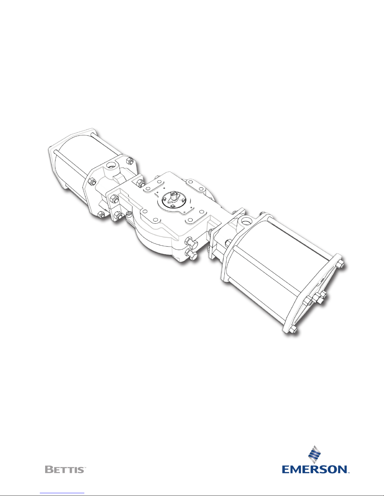
Bettis RGS F-Series Double-Acting Actuators


Installation, Operation and Maintenance Manual
RGS011110-2 Rev. 0
Table of Contents
Section 1: Overviewn �����������������������������������������������������������1
Section 2: Installation �����������������������������������������������������������2
2.1 Valve Attachment ....................................................................................... 3
2.2 Accessory Mounting ................................................................................... 4
2.3 Piping and Operation .................................................................................. 4
2.4 Travel Adjustment ....................................................................................... 7
Section 3: Troubleshooting ��������������������������������������������������9
Section 4: Maintenance ������������������������������������������������������ 10
4.1 Periodic Maintenance Schedule ................................................................ 10
4.2 Lubrication................................................................................................ 10
4.3 Piston Seal Replacement ........................................................................... 10
4.4 Rod Seal Replacement .............................................................................. 13
4.5 Yoke Seal and Bushing Replacement ......................................................... 15
4.6 Pins and Rollers Replacement ................................................................... 19
Table of Contents
April 2016
Appendix A: ������������������������������������������������������������������������21
A.1 Force Module ............................................................................................ 21
A.2 Torque Module .......................................................................................... 23
Table of Contents
I

Section 1: Overview
April 2016
Section 1: Overview
NOTE:
All activities must be carried out in order to ensure proper actuator operation. Always
read all instructions before beginning maintenance.
Bettis RGS F-Series actuators are composed of three basic sub-assemblies, two force
modules and a torque module. The force modules contain the pistons which provide
linear motion. The torque module contains the yoke which converts the force modules’
linear motion into torque and operates the valve.
Every actuator assembled by Bettis is tested prior to shipment to our customers.
Order specific documentation may be available upon request.
Installation, Operation and Maintenance Manual
RGS011110-2 Rev. 0
1
Overview

Installation, Operation and Maintenance Manual
RGS011110-2 Rev. 0
Section 2: Installation
Bettis actuators may be mounted in any position/orientation. If necessary, lift the actuator
with straps placed inside the framework of the body. Never lift the actuator by the cylinders,
tie rods, or travel stops. Lifting the actuator with the valve attached is not generally
recommended.
Figure 1
Section 2: Installation
April 2016
Installation
2

Section 2: Installation
April 2016
Larger sizes have lifting eyes incorporated into their body section which may be used to
lift the actuator.
Figure 2
Installation, Operation and Maintenance Manual
RGS011110-2 Rev. 0
2�1 Valve Attachment
NOTE:
Prior to mounting the actuator, verify alignment of coupler and shaft to ensure that the
valve will move to correct position.
Ensure the actuator is in the same position as the valve. It may be necessary to stroke
the actuator to determine the correct mounting orientation. Attach the actuator to the
valve using the proper bracket and coupler, or with a Bettis Universal Mounting Plate
(UMP) if provided. Using all mounting holes indicated on Bettis dimensional drawings,
tighten all fasteners hand tight then torque the fasteners to the corresponding value on
the table below.
Table 1�
Thread Pattern Ft-Lbs Nm
Accessories M5 3.4 4.6
F2200 M12 49 66
F2250/2300 M16 120 162
F2375 M20 235 318
F2488 M24 400 543
F2575 M30 800 1084
3
Installation

Installation, Operation and Maintenance Manual
RGS011110-2 Rev. 0
2�2 Accessory Mounting
As a standard, Bettis RGS F-Series actuators are provided with female 4mm slotted accessory
mounting geometry. When installing accessories, such as switch boxes or positioners,
tighten accessory mounting bolts hand tight, stroke the actuator three times to ensure
proper alignment then tighten the accessory mounting bolts to the proper torque. Check
the dimensional drawing or associated product bulletin for exact dimensions.
2�3 Piping and Operation
The operation of a Bettis RGS F-Series Double-Acting (DA) actuator is comparable to any
double-acting scotch yoke actuator.
Instrument air, water, and other power gases and fluids may be used to cycle the actuator so
long as construction materials were chosen accordingly and maximum allowable pressure is
not exceeded. Air driven stainless-steel actuators with stainless-steel or composite cylinders
are not harmed by wet air (so long as freezing does not occur). Aluminum and chromeplated steel cylinders may be harmed over time by the presence of water.
Section 2: Installation
April 2016
WARNING: DO NOT EXCEED PRESSURE RATING
Exceeding the stated maximum pressure may result in damage to equipment and danger
to personnel including severe injury or death. Consult the actuator label for operating
limits. If an actuator label is missing, contact Bettis to request a replacement.
WARNING: DO NOT EXCEED TEMPERATURE RATING
Operating outside of the minimum and maximum temperature range may result in damage
to equipment and danger to personnel including severe injury or death. Consult the
actuator label for operating limits. If an actuator label is missing, contact Bettis to request a
replacement. An example of an actuator label is provided below for your reference.
NOTE:
CE marking indicates product conforms to the requirements of applicable directives as
listed on the actuator label.
Installation
4
Section 2: Installation
April 2016
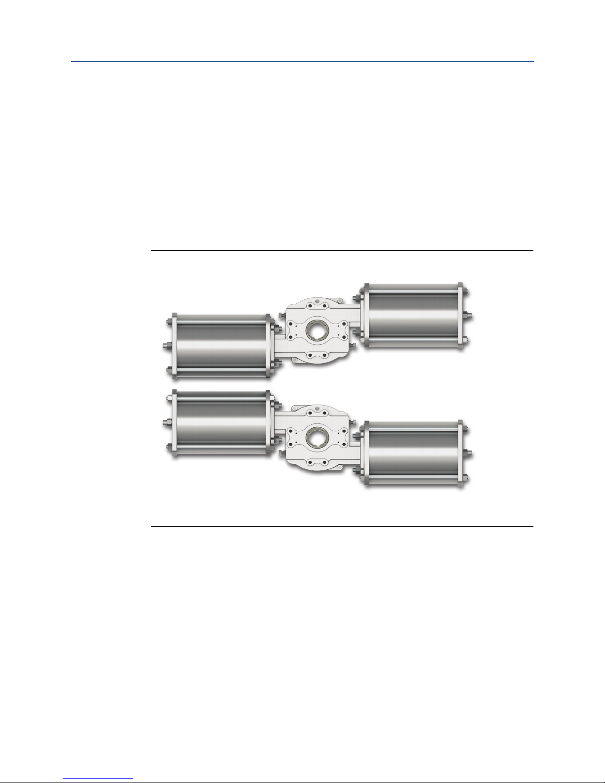
All Bettis actuators are shipped in the Left-Hand orientation unless ordered as RightHand. The orientation may be reversed in the field by moving all accessories to the
opposite side of the shaft and turning the actuator top–side down.
Double-Acting (Left-Hand): pressure on the end cap ports pushes the pistons inward
and causes counterclockwise rotation. Pressure to the base plate ports pushes the
pistons outward resulting in a clockwise rotation.
Double-Acting (Right-Hand): pressure on the end cap ports pushes the pistons inward
and causes clockwise rotation. Pressure to the base plate ports pushes the pistons
outward resulting in a counterclockwise rotation.
Figure 3
Installation, Operation and Maintenance Manual
RGS011110-2 Rev. 0
Left-Hand
Right-Hand
5
Installation
Installation, Operation and Maintenance Manual
RGS011110-2 Rev. 0
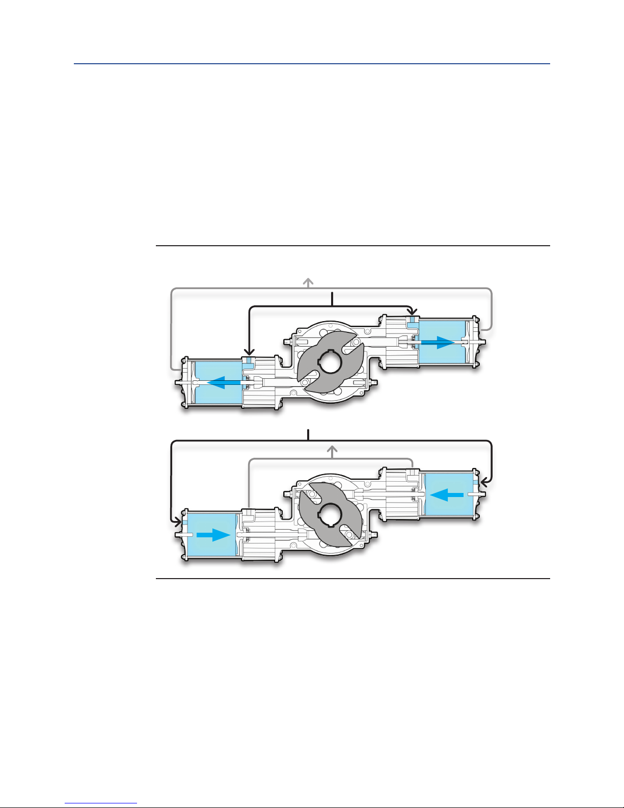
Piping Guidelines:
• Both end cap pressure ports (P1 and P2) and both base plate pressure ports
(P3 and P4) must be utilized for proper operation.
• P1 and P2 are typically connected and powered by a single air pathway.
• P3 and P4 are typically connected and powered by a single air pathway.
• P5 is a breather port that should be fitted with a filter or strainer.
• On double-acting models, P5 may also be plugged without affecting
actuator operation.
Figure 4
Section 2: Installation
April 2016
P1
P1
P3
P3
P5 (2)
P5 (2)
P4
P2
P4
P2
Installation
6
 Loading...