

Page 1
ATEX Reference Guide EL Electric actuators
English
DeutschFrançais
WWW.EL-O-MATIC.COM
Español
DOC.ATX.EL.1
Nederlands
Page 2

1 Installation
English
CAUTION
* Do not attempt to store, install, or operate your
El-O-Matic EL actuator without taking account
of the following;
1.1 Electrical wiring
1 The control circuitry feeding the actuator must not
allow power to be supplied to both "open" and
"close" motor windings at the same instance in
time.
* Example: when power is applied to the "open"
terminal, the "close" terminal must be isolated
from the power supply and vice versa.
* Failure to do so will result in the motor overheat-
ing.
2 If several actuators are controlled from a common
control switch, which has only a D.P.D.T. type
electrical contact on it, then the result can be that
the actuators will run in different directions.
* Example: An open/stop/close switch with only
D.P.D.T. contacts on it controls three actuators.
* When the switch is turned to the open control
position, all three actuators will start to run open. If
any one of the three actuators reaches its open
position before the other two it can receive power
via the common D.P.D.T. contacts and the other
actuators close motor winding, resulting in that
actuator running closed.
3 When several actuators are required to be
controlled in parallel with one 3-position switch,
that switch must have separate contacts for each
actuator being controlled.
4 Use wire with proper gauge and insulation. (follow
standards prescribed by the relevant electrical
code)
5 Actuator chassis must be correctly grounded.
6 Use appropriate conduit or cable glands for
weather proof or explosion proof applications.
7 Follow the wiring diagram to ensure proper
connection of power and control voltage to the
actuator.
8 Make all splices or connections using the correct
pin connector or terminal strip.
9 Always connect anti condensation heater.
1.2 Storage
1.2.1 Warehouse Storage
1 Actuators should be stored in a clean, dry
warehouse free from excessive vibration and rapid
temperature change.
2 Actuators should not be stored on any floor
surface.
3 In areas of high humidity the actuator should have
a packet of desiccant placed in the motor
compartment. (this will absorb excessive
moisture)
1.2.2 On Site Storage
1 Actuators should be stored in a clean, dry location
free from excessive vibration and rapid temperature change.
2 Ensure all actuator covers are in place and
securely fastened.
3 If power is not available, place a packet of
desiccant in the motor compartment. (replace
cover and securely fasten)
4 Replace plastic conduit plugs with appropriate
pipe plugs.
Important
* Failure to follow proper storage guidelines will
void warranty.
2DOC.ATX.EL.1 Rev.: - May ‘03
Page 3
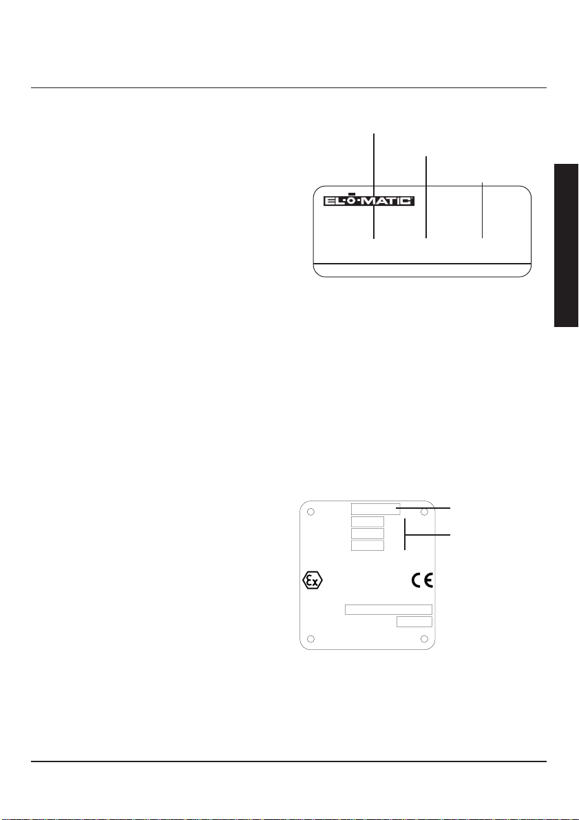
2 Identification
1.3 Do
1 Keep motor compartment clean and dry.
2 When applicable connect the compartment heater.
3 Check unit wiring and ensure it coincides with the
proper wiring diagram.
4 Power supply should be free from excessive
voltage transients (spikes).
5 Control lines should be shielded properly.
6 CAUTION: Shut off incoming power before
installing or repairing any electrical device.
7 Check motor nameplate to be certain that the
actuator voltage is the same as your incoming
voltage.
8 Schedule a periodic maintenance check of all El-
O-Matic actuators to prolong life and ensure
proper performance (we suggest check for correct
opening and closing once a month).
9 Set open and close limit switches manually, in
accordance with instructions.
10 Be sure and lubricate unit during reassembly. (see
LUBRICATION)
11 Check limit switch setting prior to motor operation
if the actuator has been repaired or disassembled.
1.4 Don’t
1 CAUTION: Do not attempt to install or repair any
electric device without shutting off incoming power.
2 Do not operate valve without first setting limit
switches and checking direction of motor rotation.
3 Release torque before disassembling gear train
components or the actuator from the valve.
4 Do not adjust torque switch settings. (these are
factory set and need no adjustment)
5 Do not use a cheater or extension bar on the
handwheel. (this could result in damage to the
valve assembly or cause physical injur y)
6 Do not alternately start and stop motor to seat or
un-seat a valve. f properly sized, the running
torque of the actuator should seat the valve in
normal operation.
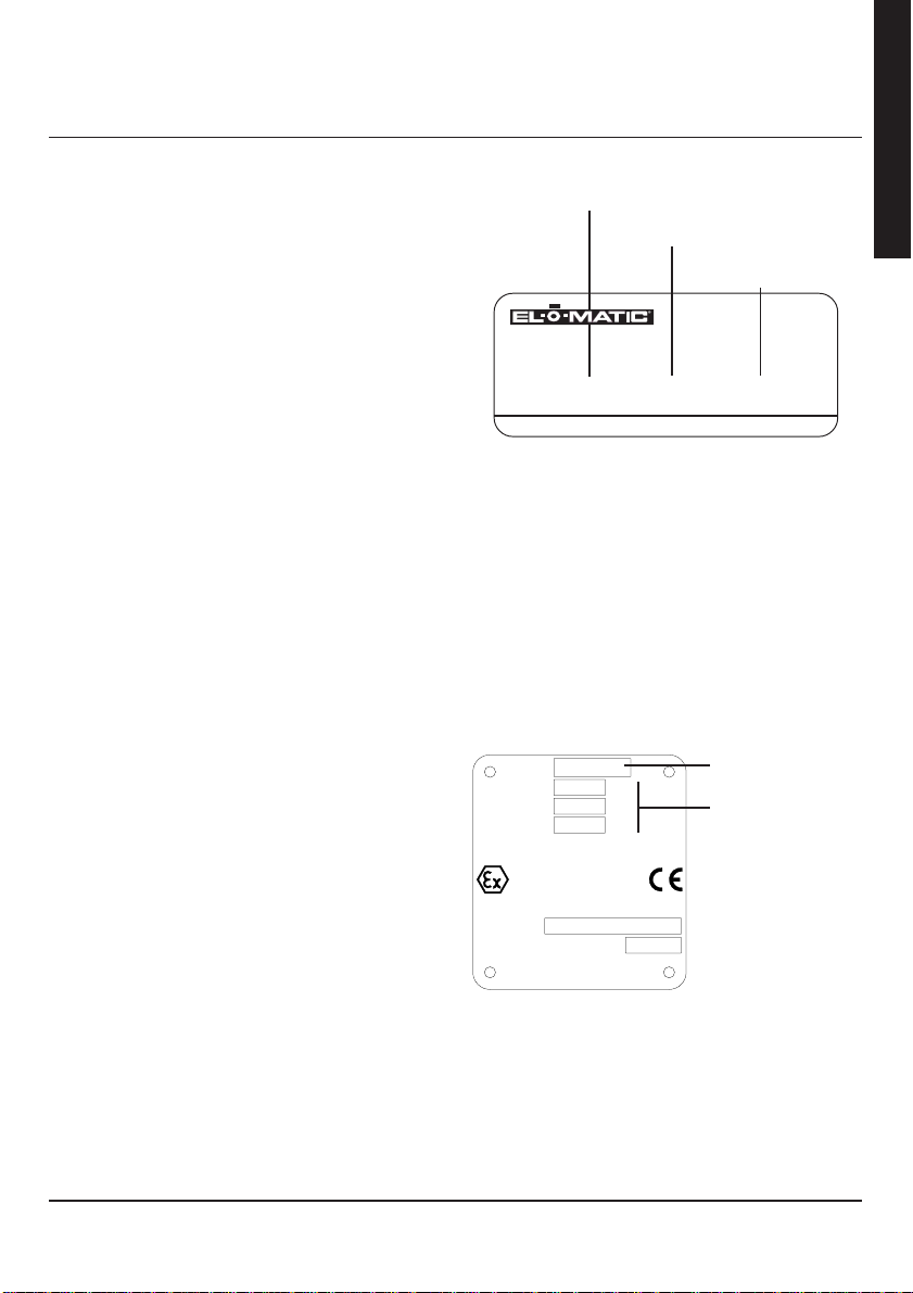
A Weather proof exectution
Actuator size
WWW.EL-O-MATIC.COM
TYPE
SERIAL No.
B ATEX approved execution
WARNING
* Actuator must be isolated electronically before any
(dis)assembly is begun.
* Before mounting or (dis)assembling the actuator
consult the relevant sections of this manual.
* The ATEX explosion proof certified EL electric
actuator is a Group II category 2 equipment and
intended for use in areas in which explosive
atmospheres caused by mixtures of air and gases,
vapours or mists or by air/dusts mixtures are likely
to occur.
Type:
Cable compatible with a temperature
ELXXXX XXXXXX XXXXX
XXXXXXXXXXXXXX
EL 150
240
U:
0.5
I:
50
f:
of 130˚C
V
A
Hz
Power supply
specifications
Electrical entry
dimensions
Actuator size
Power supply
specifications
II 2 G EEx d IIB T4
KEMA 03ATEX2156 X
Serial No.:
Year of manufacturing:
Manufacturer : EL-O-MATIC B.V.
7556BR, The Netherlands
English
DOC.ATX.EL.1 Rev.: - May ‘03
3
Page 4
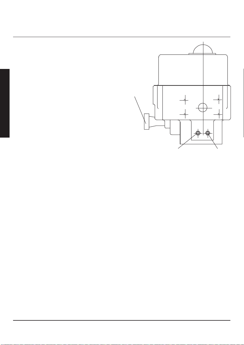
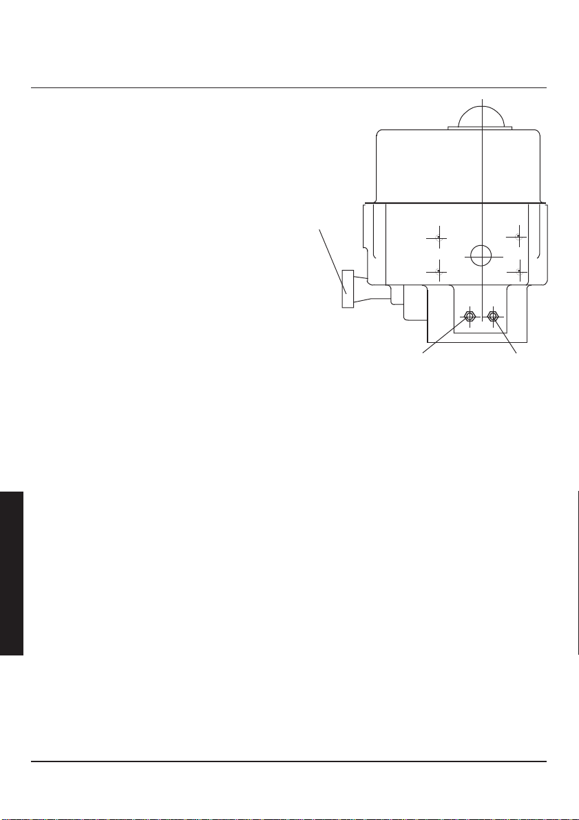
3 Mechanical Limit stop setting
English
All El-series electric actuators are equipped with a
manual override feature and a Stroke Adjustment
System. The purpose of this system is to limit the
stroke of the valve while under manual control.
On torque switch equipped actuators the limit stops
may be used to provide a greater degree of stroke
precision than by limit switches. ie. for high performance butterfly valves.
After the actuator has been fitted on a valve and the
end of travel limit switches have been set, the
mechanical stops can be set as
follows:
Important.
* For torque seated applications the mechanical
stops do not need setting in the positions that
torque seating is required and the stop screws
should be backed off approx. 2 turns from the
fully closed or open position. This to prevent the
torque switch from tripping on the stop screws
and not on the valve seat.
3.1 Procedure
1 With actuator mounted to a valve, electrically or
manually move the valve away from the fully open
position.
2 Turn the open stop screw out (ccw) 4 turns.
3 Manually operate the actuator to the full open
position.
4 Now turn the open stop screw in (cw) until an
obstruction is felt (do not force) then backoff 1/2
turn and lock the stop screw with the locknut.
5 Follow the same procedure at the closed end of
travel and adjust the “close” stop screw the same
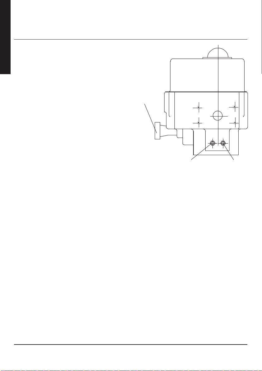
way .
Manual
override
handwheel
OPEN (Counter
Clockwise)
Fig 3.1 Location of Limit Stops
CLOSE
(Clockwise)
4DOC.ATX.EL.1 Rev.: - May ‘03
Page 5
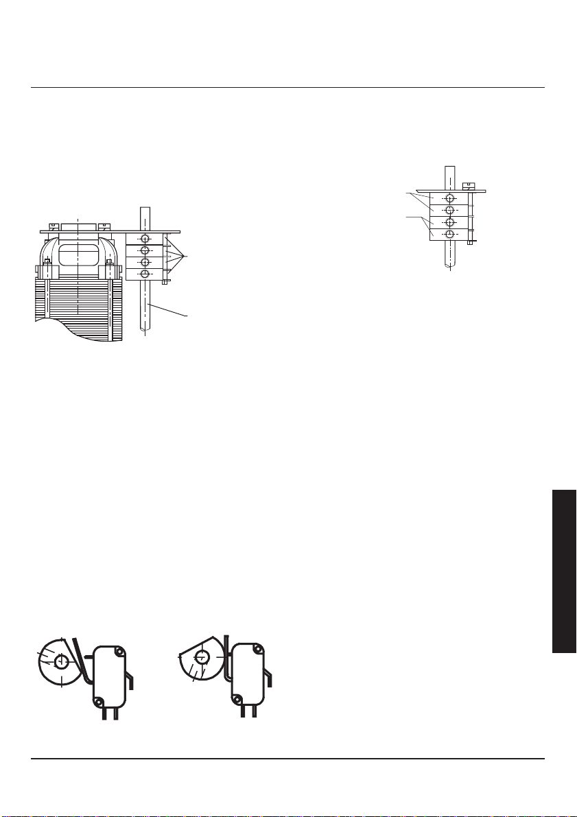
4 Limit Switch Settings
The end of travel limit switches have been factory set
for approximately 90° of valve travel. They will however
coincide with the exact end of valve travel positions.
The switches and their operating cams are located
under the limit switch bracket which is fixed to the top
of the motor.
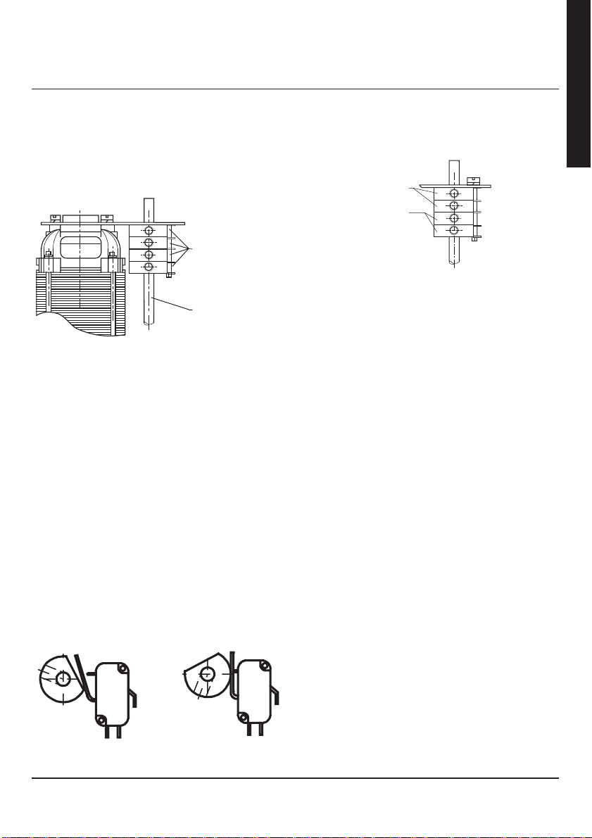
Limit switches
and cams
Indicator shaft
fig. 4.1. Location of Limit Switches
Important
* Set mechanical stops before setting limit
switches.
* The switches should be adjusted after the
actuator is installed on the valve and after the
mechanical stops have been set.
* The motor is de-energized once the flatted side
of the cam is in contact with the limit switch
actuator arm, and the switch is no longer
depressed.
* Capacitor may be removed from the limit switch
bracket for better access.
* For more precise setting you can leave the allen
wrench in the cam during setting procedure.
4.1 Procedure
1 Remove actuator cover.
2 The limit switches are marked “1” for close and “2”
for open.
Primary Switches / cams
Extra Switches / cams
1 CLOSED (red)
2 Open (green)
3 (gray)
4 (gray)
fig. 4.4 Switch Functions.
4.1.1 CCW (Open) switch setting
3 Manually or electrically rotate actuator/valve to the
desired position.
4 REMOVE ELECTRICAL POWER.
5 Using a 2mm allen wrench loosen set screw on
cam.
6 Rotate green cam until switch lever arm r ides on
the curved portion of the cam. (fig 1d).
7 Rotate cam counter-clockwise until the switch
trips.
This can be detected by a slight audible “click”, or
use a battery powered test light across terminal 8
and 10.
8 Tighten set screws.
9 Electrically cycle the actuator to check switch
setting.
4.1.2 CW (Close) limit switch setting
10 Manually or electrically rotate actuator/valve to the
desired position.
11 REMOVE ELECTRICAL POWER.
12 Using a 2mm allen wrench loosen set screw on
cam.
13 Rotate red cam until switch lever arm r ides on the
curved portion of the cam (fig 1d).
14 Rotate cam clockwise until the switch trips. This
can be detected by a slight audible “click”, or use a
battery powered test light across terminal 5 and 7.
15 Tighten set screws.
16 Electrically cycle the actuator to check switch
settings.
English
fig. 4.2. Switch Break
Position
DOC.ATX.EL.1 Rev.: - May ‘03
fig. 4.3. Initial
Position
5
Page 6

1 Einbauhinweise
Achtung
* Zur Einlagerung, Montage und Inbetriebnahme
Ihres El-O-Matic EL-Stellantriebs sollten Sie
unbedingt folgende Einbauhinweise beachten!
1.1 Elektrische Verkabelung
1 Der Steuerschaltkreis, der den Stellantrieb mit
Strom versorgt, darf nicht zulassen, daß den
Motorwicklungen “öffnen” und “Schließen”
gleichzeitig Strom zugeführt wird.
* Beispiel: Wenn die Anschlußklemme “öffnen” unter
Strom gesetzt wird, muß die Anschlußklemme
Deutsch
“Schließen” von der Stromversorgung getrennt
werden, und umgekehrt.
* Geschieht dies nicht, führt das zu einer Überhit-
zung des Motors.
2 Wenn mehrere Stellantriebe durch einen
gemeinsamen Steuerschalter mit nur einem
zweipoligen elektrischen Umschaltkontakt
gesteuert werden, könnten die Stellantriebe
Steuervorgänge in verschiedene Richtungen
veranlassen.
* Beispiel: Ein öffnen - Stopp - Schließschalter mit
ausschließlich zweipoligen Umschaltkontakten
steuert drei Stellantriebe. Wenn der Schalter in die
Aufsteuerstellung gebracht wird, wird an allen drei
Stellantrieben der Aufsteuervorgang gestartet.
* Wenn einer der drei Stellantriebe vor den anderen
beiden die Offen-Stellung erreicht, kann er Strom
über die gemeinsamen zweipoligen Umschaltkontakte und die Schließ-Motorwicklung der
anderen Stellantriebe beziehen. Daraufhin startet
der betreffende Stellantrieb den Zusteuervorgang.
3 Wenn mehrere Stellantriebe in Parallelschaltung
mit einem Dreiwegeschalter geregelt werden
müssen, muß dieser Schalter getrennte Kontakte
für jeden zu steuernden Stellantrieb besitzen.
1.2 Hinweise zur Lagerung
Ohne vorschriftsmäßige Lagerung oder Montage sind
die Antriebe nicht witterungsbeständig
1.2.1 Lagerung in geschlossenen
Räumen
1 Stellantriebe sind in sauberen, trockenen Räumen
frei von übermäßig starken Schwingungen und
schnellen Temperaturwechseln zu lager n.
2 Stellantriebe dürfen nicht auf dem blanken
Erdboden gelagert werden.
3 In Räumen mit hoher Luftfeuchtigkeit ist ein Paket
Entfeuchtungsmittel mit ins Motorgehäuse
einzulegen (zum Entzug überschüssiger
Feuchtigkeit).
1.2.2 Lagerung im Freien
1 Stellantriebe dürfen nicht auf dem blanken
Erdboden gelagert werden.
2 Stellantriebe sind an einem sauberen, trockenen
Ort frei von übermäßig starken Schwingungen und
schnellen Temperaturwechseln zu lager n.
3 Zur Vermeidung von Kondenswasser sind die
Gehäuseheizungen von fachkundigen Elektrikern
anzuschließen.
4 Es ist sicherzustellen, daß an den Stellantrieben
alle Abdeckungen angebracht und sicher befestigt
sind.
5 Wenn keine Anschlußmöglichkeiten an elektri-
schen Strom vorhanden sind, ist ein Paket
Entfeuchtungsmittel in das Motorgehäuse zu legen
(Abdeckung wieder aufsetzen und sicher
befestigen).
6 Kunststoffkappen durch geeignete
Rohrverschlußstopfen auswechseln. Für Schäden,
die durch unsachgemäße Lagerung entstehen,
entfällt die Garantie.
6DOC.ATX.EL.1 Rev.: - Mai ‘03
Page 7
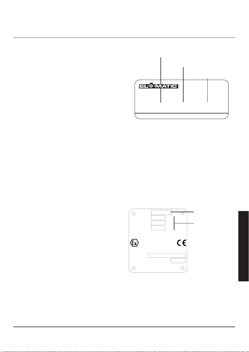
2 Identifizierung
1.3 Achtung:
* Bei allen Arbeiten an elektrischen Geräten ist
vorher unbedingt die Stromzufuhr abzuschalten!
1 Halten Sie das Motorgehäuse sauber und trocken.
2 Schließen Sie gegebenenfalls die Gehäuse-
heizung an.
3 Kontrollieren Sie, ob die Geräteverdrahtung dem
einschlägigen Verdrahtungsplan entspricht.
4 Die Stromversorgung soll sauber und ordnungsge-
mäß geerdet sein.
5 Steuerleitungen sind ordnungsgemäß abzuschir-
men.
6 Überprüfen Sie das Typenschild darauf, ob die
Betriebsspannung Ihres Stellantriebs auch wirklich
der Eingangsspannung entspricht.
7 Planen Sie die Wartungsintervalle Ihrer El-O-
Matic-Stellantriebe so ein, daß ihre Lebensdauer
verlängert und ihre Leistung sichergestellt wird
(unser Vorschlag: eine Kontrolle pro Monat).
8 Die Öffnungs- und Schließstellungen der
Endschalter sind vorschriftsmäßig von Hand zu
justieren (siehe Seite 8).
9 Beim Wiedereinbau ist der Stellantrieb unbedingt
abzuschmieren (siehe SCHMIERUNG).
10 Nach allen Reparatur- oder Demontagearbeiten
sind vor Wiederinbetriebnahme die
Endschalterstellungen des Motors zu überprüfen.
1.4 Warnungen
1 Betätigen Sie keine Armatur, ohne die Endschalter
eingestellt und die Drehrichtung des Motors
überprüft zu haben.
2 Hände weg von einem Stellantrieb, der durch zu
hohes Drehmoment festgesetzt worden ist.
3 Verstellen Sie keine Drehmomentschalter (diese
sind im Werk vorjustiert und brauchen nicht
nachgestellt zu werden).
4 Benutzen Sie zur Handradverstellung keine
Überbrückungen oder Verlängerungen. Damit
könnten Sie die Einheit beschädigen oder sich
verletzen.
5 Um eine Armatur zu schließen oder zu
öffnen,sollten Sie keinesfalls den Motor abwechselnd anfahren und stoppen. Bei richtiger
Auslegung sollte das Anfahrmoment ausreichen,
um die Armatur ordnungsgemäß zu betätigen.
A Wetterfeste Ausführung
Größe des Stellantriebs
Stromversorgungsdaten
Abmessungen des
elektrischen Eingangs
WWW.EL-O-MATIC.COM
TYPE
SERIAL No.
B ATEX-genehmigte Ausführung
ACHTUNG
* Der Stellantrieb muss vor jedweder (De-)Montage
elektrisch isoliert werden.
* Lesen Sie vor der Anbringung oder (De-)Montage
des Stellantriebs die entsprechenden Abschnitte
dieses Handbuchs.
* Der ATEX-explosionsgeschützte elektrische
Stellantrieb ist ein Gerät der Gruppe 2, Kategorie
2 und konzipiert für den Einsatz in Gebieten, in
denen explosionsgefährliche Atmosphären durch
Mischungen von Luft und Gasen, Dämpfen oder
Nebeln oder Luft?/Staubmischungen
wahrscheinlich sind.
Type:
Cable compatible with a temperature
ELXXXX XXXXXX XXXXX
XXXXXXXXXXXXXX
EL 150
240
U:
I:
f:
0.5
50
of 130˚C
V
A
Hz
Größe des
Stellantriebs
Stromversorgungsdaten
II 2 G EEx d IIB T4
KEMA 03ATEX2156 X
Serial No.:
Year of manufacturing:
Manufacturer : EL-O-MATIC B.V.
7556BR, The Netherlands
Deutsch
7DOC.ATX.EL.1 Rev.: - Mai ‘03
Page 8
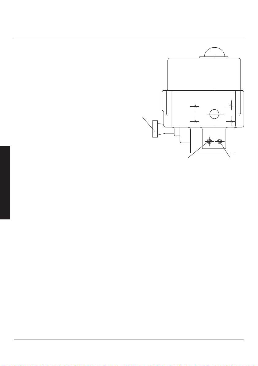
3 Einstellung der mechanischen Endanschläge
Alle mit manuellem Überlauf ausgerüsteten elektrischen Stellantriebe der EL-Serie besitzen einen
einstellbaren mechanischen Endanschlag.
Diese Einrichtung soll dazu dienen, den Hub der
Armatur unter manueller Steuerung oder bei
Funktionsausfall der Endschalter zu begrenzen.
Nach Montage des Stellantriebs an einer Armatur und
nach Einstellung des Schaltweges können die
mechanischen Endanschläge wie folgt eingestellt
werden:
Deutsch
Wichtig:
* Beim Einsatz drehmomentgesteuerter Armatu-
ren brauchen die mechanischen Endanschläge
nicht auf die Positionen einstellt zu werden, die
die Drehmomentsteuerung vorschreibt, sondern
die Anschlagschrauben sind ca. 2 Umdrehungen von der vollständig geöffneten bzw.
geschlossenen Stellung wegzudrehen. Damit
wird verhindert, daß der Drehmomentschalter
an den Endanschlagschrauben und nicht am
Armaturensitz anspricht.
3.1 Procedure
1 Die Armatur elektrisch oder manuell von der voll
geöffneten Stellung zurückfahren.
2 Die Endanschlagschraube in “Auf”-Stellung 4
Umdrehungen herausdrehen (gegen den
Uhrzeigersinn).
3 Den Stellantrieb elektrisch (nicht von Hand) in die
voll geöffnete Stellung fahren, bis der Endschalter
den Motor abschaltet.
4 Nun die Endanschlagschraube in “Auf”-Stellung
(im Uhrzeigersinn) eindrehen, bis Gegendruck
spürbar wird (nicht forcieren!), dann 1/2 Drehung
zurückdrehen und die Endanschlagschraube mit
Kontermutter sichern.
5 Für die “Zu”-Stellung gelten die Schritte 1. bis 4.
entsprechend, nur daß anstatt “Auf” die “Zu”Stellung gemeint ist.
Handrad für
manuellem
Überlauf
Abb. 3.1 Hubbegrenzungsschrauben
AUF (gegen den
Uhrzeigersinn)
ZU (im
Uhrzeigersinn)
8DOC.ATX.EL.1 Rev.: - Mai ‘03
Page 9

4 Einstellung der Endschalter
Die Endschalter sind werksseitig auf ca. ±90° des
Armaturschaltwegs voreingestellt. Sie stimmen jedoch
mit dem genauen Endlagen überein. Die Schalter und
ihre Betätigungsnocken befinden sich unter der
Endlagenschalterkonsole, die oben am Motor
befestigt ist.
Endschalters und
Nocken
Schalterwelle
Abb. 4.1 Endschaltanordnung
WICHTIG
* Stellen Sie die mechanischen Anschläge ein,
bevor Sie die Endschalter einstellen.
* Die Schalter müssen angepaßt werden,
nachdem der Stellantrieb am Ventil installiert
wurde und nachdem die mechanischen
Anschläge eingestellt worden sind.
* Der Motor wird abgeschaltet, sobald die
abgeflachte Seite des Nockens den Auslösehebel des Endschalters berührt und der Schalter
nicht mehr betätigt wird.
* Um besser an die obere Seite der Motorplatte
heranzukommen, müssen Sie möglicherweise
den Kondensator ausbauen.
* Für ein präziseres Einstellen können Sie den
Inbusschlüssel während der Justage im Nocken
belassen.
4.1 Procedure:
1 Entfernen Sie den Schaltergehäusedeckel.
2 Die Endschalter des Armaturschaltwegs sind mit
“1” für Zu und “2” für Auf gekennzeichnet.
original Schalternocken
zusätzliche Endschalter und
Nocken
1 Zu (Rot)
2 Auf (Grün)
3 Grau
4 Grau
Abb 4.4 Schaltfunktionen
4.1.1 Nocken-/Schalterstellung AUF:
3 Drehen Sie den Stellantrieb bzw. die Armatur
manuell oder elektrisch in die gewünschte
Öffnungsposition.
4 Schalten Sie die Stromversorgung ab.
5 Lösen Sie die Stiftschraube am Nocken mit Hilfe
eines 2 mm Inbusschlüssels.
6 Drehen Sie den grünen Nocken im Uhrzeigersinn
vom Schalter weg , bis der Schalterhebel auf dem
Nockenbuckel aufliegt.
7 Drehen Sie den grünen Nocken gegen den
Uhrzeigersinn, bis er hörbar einrastet.
8 Ziehen Sie die Stiftschrauben fest.
9 Prüfen Sie die Schalterstellungen, indem Sie den
Stellantrieb kurz elektrisch angetrieben laufen
lassen.
4.1.2 Nocken-/Schalterstellung ZU:
10 Drehen Sie den Stellantrieb bzw. die Armatur
manuell oder elektrisch in die gewünschte
Schließposition.
11 Schalten Sie die Stromversorgung ab.
12 Lösen Sie die Stiftschraube am Nocken mit Hilfe
eines 2 mm Inbusschlüssels.
13 Drehen Sie die Roten Nocken gegen den
Uhrzeigersinn vom Schalter weg , bis der
Schalterhebel auf dem Nockenbuckel aufliegt.
14 Drehen Sie den Roten Nocken im Uhrzeigersinn,
bis er hörbar einrastet.
15 Ziehen Sie die Stiftschrauben fest.
16 Prüfen Sie die Schalterstellungen, indem Sie den
Stellantrieb kurz elektrisch angetrieben laufen
lassen.
Deutsch
Abb 4.2 Unterbrecher-
position
Abb 4.3 Schalt
Position
9DOC.ATX.EL.1 Rev.: - Mai ‘03
Page 10

1 Installation
AVERTISSEMENT
Ne pas entreprendre d’entreposer, installer ou
exploiter l’actionneur El-O-Matic de Série EL
sans avoir pris connaissance de ce qui suit :
1.1 Cablage electrique
1 Le circuit de contrôle alimentant l’actionneur ne
doit pas alimenter les deux enroulements du
moteur « ouvert » et « fermé » au même moment.
* Par exemple, si l’alimentation est fournie à la
borne « ouverte », la borne « fermée » ne doit pas
être alimentée et vice et versa.
* Auquel cas le moteur risque de fonctionner en
surchauffe.
2 Si plusieurs actionneurs sont contrôlés par un seul
interrupteur de contrôle, ayant un seul contact de
type D.P.D.T., les actionneurs peuvent se mettre à
fonctionner dans différentes directions.
* Par exemple : Un interrupteur ouvert/arrêt/fermé
dotés uniquement de contacts D.P.D.T. contrôle
trois actionneurs. Lorsque l’interrupteur est amené
en position ouverte de contrôle, les trois
actionneurs commencent à se mettre en position
ouverte.
* Si un des trois actionneurs atteint la position
Français
ouverte avant les deux autres, il peut être alimenté
via les contacts D.P.D.T. communs tandis que les
autres actionneurs entraînent la fermeture de
l’enroulement du moteur et ce faisant ladite
fermeture des actionneurs.
3 Quand plusieurs actionneurs doivent être
contrôlés en parallèle avec un interrupteur à 3
position, ledit interrupteur doit avoir des contacts
séparés pour le contrôle de chaque actionneur.
4 Utiliser un fil correctement isolé avec calibre
approprié. (se tenir aux dispositions imposées par
le code électrique correspondant)
5 Le châssis de l’actionneur doit être correctement
mis à la terre.
6 Utiliser les raccords de conduit ou de câble
appropriés pour les applications à l’épreuve des
intempéries ou des explosions.
7 Se reporter au schéma de câblage pour assurer le
bon branchement de l’alimentation et de la tension
de contrôle à l’actionneur.
8 Faire toutes les épissures ou jonctions à l’aide du
connecteur à broches ou du bornier approprié.
9 Toujours relier un élément chauffant à l’épreuve de
la condensation.
1.2 Entreposage
1.2.1 Entreposage en magasin
1 Entreposer les actionneurs dans un magasin
propre, sec et à l’abri de vibrations excessives et
de variations de température rapides.
2 Ne pas entreposer les actionneurs à même le sol.
3 Dans les zones exposées à une forte humidité,
placer un sachet desséchant dans le comparti-
ment du moteur de l’actionneur. (cela absorbera
l’humidité excessive)
1.2.2 Entreposage sur site
1 Entreposer les actionneurs dans un endroit
propre, sec et à l’abri de vibrations excessives et
de variations de température rapides.
2 S’assurer que tous les couvercles de l’actionneur
sont en place et bien fixés.
3 En l’absence de courant, placer un sachet
desséchant à l’intérieur du compartiment du
moteur. (remettre le couvercle en place et bien le
fixer)
4 Remplacer les bouchons de conduit en plastique
par des bouchons de tube appropriés.
Important
* Le non-respect des directives en matières
d’entreposage entraîne l’annulation de la
garantie.
10DOC.ATX.EL.1 Rev.: - Mai ‘03
Page 11

1.3 A faire
1 Conserver le compartiment du moteur en bon état
et sec.
2 Si nécessaire, relier un élément chauffant pour le
compartiment.
3 Vérifier le câblage de l’unité et s’assurer qu’il
correspond au schéma du câblage correspondant.
4 L’alimentation électr ique doit être à l’abri des
tensions transitoires excessives (pointes de
tension).
5 Les lignes de contrôles doivent être correctement
blindées.
6 AVERTISSEMENT : Couper le courant de secteur
avant l’installation ou la réparation de tout
dispositif électrique.
7 Vérifier la plaque d’identification du moteur pour
être sûr que la tension de l’actionneur est
identique à celle de la tension d’entrée.
8 Prévoir un contrôle de maintenance périodique de
tous les actionneurs El-O-Matic pour en allonger la
durabilité et en garantir le bon fonctionnement.
(nous vous conseillons de faire un contrôle de
l’ouverture et de la fermeture une fois par mois).
9 Régler manuellement les interrupteurs de fin de
course en position ouverte et fermée, conformément aux instructions.
10 Vérifier si l’unité est bien lubrifiée et lubrifier cette
dernière au cours du réassemblage. (voir
LUBRIFICATION)
11 Vérifier le réglage de l’interrupteur de fin de
course avant de faire fonctionner le moteur si
l’actionneur a fait l’objet d’une réparation ou d’un
désassemblage.
1.4 A ne pas faire
1 AVERTISSEMENT : N’entreprendre aucune
installation ou réparation d’un quelconque
dispositif électrique sans avoir coupé le courant de
secteur.
2 Ne pas mettre en marche la soupape sans avoir
réglé au préalable les interrupteurs de fin de
course et contrôlé la direction de la rotation du
moteur.
3 Desserrer le couple avant le désassemblage des
éléments du train d’engrenage ou de l’actionneur
au niveau de la soupape.
4 Ne pas procéder aux réglages des interrupteurs
de limitation de couple. (ceux-ci sont réglés à
l’usine et ne nécessitent aucun réglage)
5 N’utiliser aucune barre de rallonge sur le volant.
(cela risque de provoquer des dommages au
niveau de l’assemblage de la soupape ou causer
des lésions physiques)
6 Ne pas faire démarrer et couper le moteur en
alternance pour amener une soupape en position
d’ouverture ou de fermeture. Si le couple de
fonctionnement de l’actionneur a été bien réglé, il
devrait amener la soupape en position ouver te en
conditions de fonctionnement normal.
2 Identification
A Version résistante à l'explosion
Dimensions de l'actionneur
WWW.EL-O-MATIC.COM
TYPE
SERIAL No.
B Version approuvée ATEX
AVERTISSEMENT
* L'actionneur doit être isolé électroniquement avant
de commencer tout démontage.
* Avant de monter ou démonter l'actionneur, consulter
les sections correspondantes de ce manuel.
* L'actionneur électrique ATEX, certifié EL comme
protégé contre les explosions est un équipement
de Groupe II catégorie et est destiné à être utilisé
dans des zones où des atmosphères explosives
causées par des mélanges d'air et de gaz, de
vapeurs ou de fumées et par des mélanges d'air
et de poussières sont probables.
Type:
U:
I:
f:
Cable compatible with a temperature
II 2 G EEx d IIB T4
KEMA 03ATEX2156 X
Serial No.:
Year of manufacturing:
Manufacturer : EL-O-MATIC B.V.
7556BR, The Netherlands
11DOC.ATX.EL.1 Rev.: - Mai ‘03
Spécifications
de l'alimentation
Dimensions des
entrées électriques
ELXXXX XXXXXX XXXXX
XXXXXXXXXXXXXX
EL 150
240
0.5
50
of 130˚C
V
A
Hz
Dimensions de
l'actionneur
Spécifications de
l'alimentation
Français
Page 12
3 Butée de fin de course mécanique - Réglage
Tous les actionneurs électriques de la série EL sont
équipés d’une commande manuelle de correction et
d’un système de réglage de la course. Un tel système
a pour but de limiter la course de la soupape en cas
de commande manuelle.
Sur les actionneurs équipés d’interrupteur de
limitation de couple, les butées de fin de course
peuvent être utilisées pour obtenir une course avec
un degré de précision plus important que celui des
interrupteurs de fin de course comme par exemple
pour les vannes papillon.
Après que l’actionneur ait été installé sur une
soupape et que la fin de course des interrupteurs a
été fixée, les butées mécaniques peuvent être
réglées de la sorte :
Important.
* Pour les applications de couple de fermeture,
les butées mécaniques n’ont pas besoin d’être
réglées sur les positions en fonction du couple
de fermeture requis et les vis de butée doivent
desserrées d’environ deux tours en position de
fermeture ou ouverture totale. Ce afin d’empê-
Français
cher que l’interrupteur de limitation de couple
ne s’actionne sur les vis de butées et non pas
sur le siège de soupape.
commande
manuelle
Fig. 3.1 Emplacement des butées de fin de course
OUVERT
(dans le sens
antihoraire)
FERME
(Dans le sens
horaire)
3.1 Procédure
1 L’actionneur une fois monté sur la soupape,
déplacer électriquement ou manuellement la
soupape de sorte qu’elle ne soit plus en position
complètement ouverte.
2 Desserrer la vis de butée d’ouverture (dans le
sens antihoraire) de quatre tours.
3 Agir manuellement sur l’actionneur pour l’amener
en position complètement ouverte.
4 Serrer à présent la vis de butée d’ouverture (dans
le sens horaire) jusqu’à ce qu’elle se bloque (ne
pas forcer) puis la desserrer d’un tour et bloquer
celle-ci avec un contre-écrou.
5 Suivre la même procédure en fin de course en
position fermée et régler la vis de butée de
fermeture de la même façon.
12DOC.ATX.EL.1 Rev.: - Mai ‘03
Page 13

4 Réglage de l’interrupteur de fin de course
La fin de course des interrupteurs est réglée à l’usine
pour une course de soupape d’environ 90°. Elle ne
correspond pas exactement aux positions de fin de
course de soupape. Les interrupteurs et les cames
d’actionnement respectives se trouvent sous le
support d’interrupteur de fin de course, laquelle est
fixée au sommet du moteur.
Interrupteurs de fin
de course et cames
Arbre d’indicateur
fig. 4.1 Emplacement des interrupteurs de fin de
course
Important.
* Régler les butées mécaniques avant de passer
au réglage des interrupteurs de fin de course.
* Procéder au réglage des interrupteurs après
installation de l’actionneur sur la soupape et
après réglage des butées mécaniques.
* Le moteur est désactivé lorsque la partie plate
de la came entre en contact avec le bras de
l’actionneur de l’interrupteur de fin de course et
que ledit interrupteur n’est plus actionné
* Il est possible de libérer le condensateur du
support de l’interrupteur de fin de course pour
en faciliter l’accès.
* Pour un réglage de précision laisser la clé Allen
sur la came durant la procédure de réglage.
fig. 4.2 Position de repos
de l’interrupteur
fig. 4.3 Position
initiale
4.1 Procédure
1 Déposer le couvercle de l’actionneur.
2 Les interrupteurs de fin de course sont marqués
d’un « 1 » pour position fermée et d’un « 2 » pour
position ouverte.
Interrupteurs/cames
primaires.
Interrupteurs/cames
supplémentaires.
1 FERME/Rouge
2 OUVERT/Vert
3 Gris
4 Gris
fig. 4.4 Fonctions de
l’interrupteur.
4.1.1 Réglage de l’interrupteur dans le
sens antihoraire (position ouverte)
3 Faire pivoter l’actionneur/la soupape manuelle-
ment ou électriquement pour l’amener dans la
position souhaitée.
4 COUPER LE COURANT.
5 Desserrer la vis fixée sur la came à l’aide d’une
clé Allen de 2mm.
6 Faire pivoter la came ver te (2) jusqu’à ce que le
levier de l’interrupteur chevauche la portion courbe
de la came. (fig. 1d).
7 Faire pivoter la came ver te (2) dans le sens
antihoraire jusqu’à ce que l’interrupteur s’enclen-
che. Ceci est perceptible par un léger « clic », ou
utiliser un voyant à test alimenté par la batterie
entre les bornes 8 et 10.
8 Serrer les vis positionnées.
9 Alimenter l’actionneur pour vérifier le réglage de
l’interrupteur.
4.1.2 Réglage de l’interrupteur de fin
de course dans le sens horaire (position
fermée).
10 Faire pivoter l’actionneur/la soupape manuelle-
ment ou électriquement pour l’amener dans la
position souhaitée.
11 COUPER LE COURANT.
12 Desserrer la vis fixée sur la came à l’aide d’une
clé Allen de 2mm.
13 Faire pivoter la came rouge (1) jusqu’à ce que le
bras du levier de l’interrupteur chevauche la
portion courbe de la came (fig. 1d).
14 Faire pivoter la came rouge (1) dans le sens
horaire jusqu’à ce que l’interrupteur s’enclenche.
Ceci est perceptible par un léger « clic », ou
utiliser un voyant à test alimenté par la batterie
entre les bornes 5 et 7.
15 Serrer les vis positionnées.
16 Alimenter l’actionneur pour vérifier les réglages de
l’interrupteur.
13DOC.ATX.EL.1 Rev.: - Mai ‘03
Français
Page 14

1 Instalación
PRECAUCIÓN
No intente almacenar, instalar ni hacer funcionar
su actuador EL de El-O-Matic sin tomar en
cuenta lo siguiente:
1.1 Cableado eléctrico
1 El circuito de control que alimente el actuador no
debe permitir el suministro de corriente a los
bobinados del motor “abierto” y “cerrado” en el
mismo momento en el tiempo.
* Por ejemplo, cuando se aplica energía al terminal
“abierta”, el terminal “cerrada” debe estar aislado
de la fuente de alimentación y viceversa.
* Si esto no es así, se recalentará el motor.
2 Si se controlan varios actuadores desde un
conmutador de control común, que solamente
tiene un contacto del tipo conmutador bipolar de
dos vías, el resultado puede ser que los
actuadores funcionen en direcciones diferentes.
* Por ejemplo: un conmutador abierta/parada/
cerrada con contactos tipo conmutador bipolar de
dos vías únicamente controla tres actuadores.
* Cuando el conmutador se gira a la posición de
control abierta, los tres actuadores comenzarán a
abrirse. Si cualquiera de los tres actuadores llega
a su posición abierta antes que los otros dos,
puede recibir energía por los contactos tipo
conmutador bipolar de dos vías comunes y los
otros actuadores cerrar el bobinado del motor, con
lo cual, este actuador funcionará cerrado.
3 Cuando se necesita controlar varios actuadores
en paralelo con un conmutador de 3 posiciones,
dicho conmutador debe tener contactos separados
para cada uno de los actuadores que controla.
4 Use cable del calibre adecuado y con la aislación
correcta. (siga las normas establecidas por el
código eléctrico correspondiente)
5 El cuerpo del actuador debe estar correctamente
conectado a tierra.
Español
6 Use collarines para conducto eléctrico o cables
apropiados para aplicaciones a la intemperie o a
prueba de explosiones.
7 Siga el diagrama de cableado para asegurar la
correcta conexión de la tensión de alimentación y
de control al actuador.
8 Haga todos los empalmes o conexiones usando el
conector de clavijas o la placa de terminales
correcta.
9 Siempre conecte el calefactor anti condensación.
1.2 Almacenamiento
1.2.1 Almacenamiento en depósito
1 Los actuadores deben almacenarse en un
depósito limpio y seco, sin vibración excesiva ni
cambios bruscos de temperatura.
2 No se deben guardar los actuadores sobre el piso,
no importa cual sea su superficie.
3 En áreas de alta humedad, se debe colocar un
paquete de desecante en el compartimiento del
motor del actuador. (esto absorberá la humedad
excesiva)
1.2.2 Almacenamiento en el lugar de
uso
1 Los actuadores deben almacenarse en un lugar
limpio y seco, sin vibración excesiva ni cambios
bruscos de temperatura.
2 Asegúrese de que todas las tapas del actuador
estén colocadas y bien ajustadas.
3 Si no hay electricidad, coloque un paquete de
desecante en el compartimiento del motor. (vuelva
a colocar la tapa y ajústela bien)
4 Reemplace los tapones del conducto eléctrico de
plástico con tapones apropiados para tuberías. El
incumplimiento de las pautas de almacenamiento
apropiadas invalidará la garantía.
14DOC.ATX.EL.1 Rev.: - Mayo ‘03
Page 15
2 Identificación
1.3 Sí
1 Mantenga el compartimiento del motor limpio y
seco.
2 Cuando corresponda, conecte el calefactor del
compartimiento.
3 Controle el cableado de la unidad y asegúrese de
que coincida con el diagrama de cableado
correspondiente.
4 La alimentación de energía debe estar libre de
cambios transitorios de tensión excesivos (picos).
5 Las líneas de control deben estar correctamente
blindadas.
6 PRECAUCIÓN: Desconecte la entrada de energía
antes de instalar o reparar cualquier dispositivo
eléctrico.
7 Controle la placa de características para
asegurarse de que la tensión del actuador sea la
misma que su tensión de entrada.
8 Programe un control de mantenimiento periódico
de todos los actuadores El-O-Matic para prolongar
la vida útil y asegurar su correcto rendimiento.
(sugerimos controlar una vez por mes que abran y
cierren correctamente)
9 Configure los conmutadores limitadores abierto y
cerrado manualmente, siguiendo las instrucciones.
10 Asegúrese de lubricar la unidad durante el
rearmado (véase LUBRICACIÓN).
11 Controle la configuración de los conmutadores
limitadores antes hacer funcionar el motor si el
actuador ha sido reparado o desarmado.
1.4 No.
1 PRECAUCIÓN: No intente instalar ni reparar
ningún dispositivo eléctrico sin desconectar la
entrada de energía.
2 No haga funcionar la válvula sin configurar
primero los conmutadores limitadores y controlar
la dirección de rotación del motor.
3 Desembrague el par antes de desarmar los
componentes del tren de engranajes o el actuador
y retirarlos de la válvula.
4 No ajuste las configuraciones del conmutador de
par. (el mismo vienen configurado de fábrica y no
requieren ajuste)
5 No use un cordón eliminador de enclavamiento ni
una barra de extensión en la manivela. (esto
podría producir daños en el conjunto de la válvula
o causar lesiones físicas)
6 No arranque y pare el motor alternativamente para
asentar o desasentar la válvula. Si el
imensionamiento está correcto, el par de
funcionamiento del actuador debería asentar la
válvula durante el funcionamiento normal.
A Ejecución contra la intemperie
Tamaño del actuador
WWW.EL-O-MATIC.COM
TYPE
SERIAL No.
B Ejecución aprobada por ATEX
ADVERTENCIA
* El actuador debe aislarse electrónicamente antes
de iniciarse cualquier tarea de (des)ensamblaje.
* Antes de proceder al montaje o (des)ensamblaje
del actuador, consulte las secciones pertinentes
del presente manual.
* El actuador eléctrico EL antideflagrante certificado
por ATEX es un equipamiento del grupo II y
categoría 2 diseñado para utilizarse en zonas
propensas a la formación de atmósferas
explosivas debido a mezclas de aire y gases,
vapores o neblinas o mezclas de aire y polvo.
Type:
U:
I:
f:
Cable compatible with a temperature
Especificaciones de la
fuente de alimentación
Dimensiones de la
conexión eléctrica
ELXXXX XXXXXX XXXXX
XXXXXXXXXXXXXX
EL 150
240
0.5
50
of 130˚C
V
A
Hz
Tamaño del
actuador
Especificaciones
de la fuente de
alimentación
II 2 G EEx d IIB T4
KEMA 03ATEX2156 X
Serial No.:
Year of manufacturing:
Manufacturer : EL-O-MATIC B.V.
7556BR, The Netherlands
15DOC.ATX.EL.1 Rev.: - Mayo ‘03
Español
Page 16
3 Tope limitador mecánico: configuración
Todos los actuadores eléctricos de la serie EL están
equipados con una función de neutralización manual
y un Sistema de Ajuste de Carrera. El objeto de este
sistema es limitar la maniobra de la válvula mientras
se encuentra en control manual.
En los actuadores equipados con conmutador de par,
se pueden usar los topes limitadores para brindar un
mayor grado de precisión de maniobra que con los
conmutadores limitadores. por ejemplo, para las
válvulas de mariposa.
Una vez montado el actuador en una válvula y
configurados los conmutadores limitadores de fin de
carrera, se pueden configurar los topes mecánicos
como sigue:
Importante.
Para las aplicaciones con asentamiento de par, los
topes mecánicos no necesitan configurarse en
las posiciones en las que se requiere el
asentamiento de par y los tornillos limitadores
deben retirarse aproximadamente 2 vueltas de
la posición totalmente abierta o totalmente
cerrada. Esto es para impedir que el conmutador de par se dispare con los tornillos
limitadores y no con el asiento de la válvula.
Función de
neutralización
Fig. 3.1 Ubicación de los topes limitadores
ABRIR
(en sentido
antihorario)
CERRAR
(en sentido
horario)
3.1 Procedimiento
1 Con el actuador montado en una válvula, mueva la
válvula en forma manual o eléctrica para quitarla
de la posición totalmente abierta.
2 Abra el tornillo limitador (sentido antihorario)
girándolo 4 vueltas.
3 Haga funcionar el actuador manualmente hasta la
posición totalmente abierta.
4 Ahora gire el tornillo limitador abierto hacia
Español
adentro (en sentido horario) hasta sentir una
obstrucción (no lo fuerce) luego retroceda 1/2
vuelta y trabe el tornillo limitador con la tuerca de
retención.
5 Siga el mismo procedimiento al final de la carrera
con la válvula cerrada y ajuste el tornillo limitador
de »cierre» de la misma manera.
16DOC.ATX.EL.1 Rev.: - Mayo ‘03
Page 17
4 Configuración de los conmutadores limitadores
Los conmutadores limitadores de fin de carrera han
sido configurados en fábrica a aproximadamente el
90° de la carrera de la válvula. No coincidirán con las
posiciones exactas de fin de carrera de la válvula.
Los conmutadores y sus levas de accionamiento
están ubicados debajo de la abrazadera de conmutadores limitadores fijada en la parte superior del motor.
Conmutadores
limitadores y levas
Eje del indicador
Fig. 4.1 Ubicación de los conmutadores limitadores
Importante
* Configure los topes mecánicos antes de
configurar los conmutadores limitadores.
* Se deben ajustar los conmutadores una vez
instalado el actuador en la válvula y una vez
configurados los topes mecánicos.
* El motor está desenergizado una vez que el
lado aplanado de la leva está en contacto con el
brazo del actuador del conmutador limitador, y
el conmutador ya no está presionado.
* Se puede retirar el condensador de la abrazade-
ra de conmutadores limitadores para mejorar el
acceso.
* Para una configuración más precisa puede
dejar la llave Allen en la leva durante el
procedimiento de configuración.
Fig. 4.2 Posición de corte
del conmutador
Fig. 4.3 Posición
inicial
4.1 Procedimiento
1 Retire la tapa del actuador.
2 Los conmutadores limitadores están marcados
«1» para cerrar y «2’ para abr i r.
Conmutadores/levas
principales
Conmutadores/levas
adicionales
1 CERRADA/Rojo
2 ABIERTA/Verde
3 Gris
4 Gris
Fig. 4.4 Funciones de los
conmutadores.
4.1.1 Configuración de los
conmutadores en sentido antihorario
(Abierto)
3 Rote el actuador/válvula en forma manual o
eléctrica hasta la posición deseada.
4 DESCONECTE LA ALIMENT ACION ELÉCTRICA.
5 Con una llave Allen de 2 mm afloje el tornillo de
fijación de la leva.
6 Rote la leva verde (2) hasta que el brazo de la
palanca del conmutador cabalgue sobre la
posición curva de la leva. (fig 1d).
7 Rote la leva verde (2) en sentido antihorario hasta
que se dispare el conmutador. Esto se puede
detectar mediante un leve «clic» audible, o usando
una luz de prueba a batería, a través de los
terminales 8 y 10.
8 Ajuste los tornillos de fijación.
9 Haga ciclar el actuador eléctricamente para
controlar la configuración de los conmutadores.
4.1.2 Configuración del conmutador
limitador en sentido horario (Cerrado)
10 Rote el actuador/válvula en forma manual o
eléctrica hasta la posición deseada.
11 DESCONECTE LA ALIMENTACION ELÉCTRICA.
12 Con una llave Allen de 2 mm afloje el tornillo de
fijación de la leva.
13 Rote la leva roja (1) hasta que el brazo de la
palanca del conmutador cabalgue sobre la
posición curva de la leva (fig 1d).
14 Rote la leva roja (1) en sentido horario hasta que
se dispare el conmutador. Esto se puede detectar
mediante un leve «clic» audible, o usando una luz
de prueba a batería, a través de los terminales 5 y
7.
15 Ajuste los tornillos de fijación.
16 Haga ciclar el actuador eléctricamente para
controlar la configuración de los conmutadores.
17DOC.ATX.EL.1 Rev.: - Mayo ‘03
Español
Page 18

1 Montage
LET OP
* Houd bij het opslaan, monteren en bedienen
van de El-O-Matic EL actuator altijd rekening
met het volgende:
1.1 Elektrische bedrading
1 De regelschakeling waarmee de actuator wordt
gevoed, mag de motorwikkelingen nooit zodanig
van stroom voorzien dat deze op hetzelfde
moment worden "geopend" en "gesloten".
* Voorbeeld: Wanneer de aansluiting voor het
"openen" van stroom wordt voorzien, moet de
aansluiting voor het "sluiten" van de voeding zijn
geïsoleerd en vice versa.
* Niet-naleving van deze instructie zal tot
oververhitting van de motor leiden.
2 Als er meerdere actuators worden bediend via een
gemeenschappelijke schakelaar en deze
schakelaar uitsluitend over een tweepolig
elektrisch omschakelcontact met twee standen
(een zogenaamd D.P.D.T.-contact) beschikt, dan
kan dit tot gevolg hebben dat de actuators in
verschillende richtingen draaien.
* Voorbeeld: Een schakelaar met de standen
openen/stoppen/sluiten, die alleen over tweepolige
tweestandencontacten beschikt, stuurt drie
actuators aan.
* Wanneer de schakelaar in de stand "Openen"
wordt gedraaid, beginnen alle drie de actuators
zich naar de stand Openen te bewegen. Als een
van de drie actuators eerder dan de beide andere
actuators de geopende stand bereikt, kan deze
actuator via het "common-contact" van de
tweepolige tweestandenschakelaar en via de
"Sluiten-bedrading" van een van de andere
actuators een stroomsignaal ontvangen. Dit leidt
ertoe dat de actuator (welke het eerst geopende
stand bereikt) richting de gesloten stand beweegt.
3 Wanneer er verschillende actuators met behulp
van een driestandenschakelaar parallel moeten
worden geschakeld, moet de betreffende
schakelaar zijn uitgerust met afzonderlijke
contacten voor elke actuator die moet worden
aangestuurd.
4 Gebruik uitsluitend draden met de juiste
draadmaat en isolatie. (Houd u aan de instructies
van de toepasselijke elektrische normen.)
5 Zorg voor een juiste aarding van het
actuatorchassis.
6 Gebruik voor weersbestendige en explosieveilige
toepassingen geschikte kabelbuizen of
kabelmoffen.
7 Sluit de voedings- en regelspanning correct aan
op de actuator aan de hand van het
bedradingsschema.
8 Gebruik bij alle verbindingen en aansluitingen de
juiste pencontacten of contactstrippen.
9 Sluit altijd een condenswerende verwarming aan.
1.2 Opslag
1.2.1 Magazijnopslag
1 Actuators moeten worden opgeslagen in een
schoon en droog magazijn zonder overmatige
trillingen en snelle temperatuurschommelingen.
2 Actuators mogen niet op een vloeroppervlak
worden opgeslagen.
3 In ruimten met een hoge luchtvochtigheid moet in
het motorcompartiment van de actuator een zakje
droogmiddel worden aangebracht. (Dit absorbeert
het overtollige vocht.)
1.2.2 Opslag op locatie
1 Actuators moeten worden opgeslagen in een
schone en droge locatie zonder overmatige
trillingen en snelle temperatuurschommelingen.
2 Zorg ervoor dat alle afdekkingen van de actuator
zijn aangebracht en stevig vastzitten.
3 Plaats een zakje droogmiddel in het
motorcompartiment als er geen stroomvoorziening
aanwezig is. (Plaats het deksel terug en zet dit
stevig vast.)
4 Ver vang de kunststof buispluggen door geschikte
leidingpluggen.
Belangrijk
* Bij niet-inachtneming van de opslagrichtlijnen
vervalt elke aanspraak op garantie.
Nederlands
18DOC.ATX.EL.1 Rev.: - Mei ‘03
Page 19

1.3 Gebodsbepalingen
1 Houd het motorcompartiment schoon en droog.
2 Sluit indien nodig een compartimentverwarming
aan.
3 Controleer de bedrading van de unit en ga na of
deze overeenstemt met het toepasselijke
bedradingsschema.
4 Zorg voor een stroomtoevoer zonder overmatige
spanningspieken.
5 Zorg ervoor dat de regelkabels goed zijn
afgeschermd.
6 LET OP: Schakel de stroomtoevoer uit voordat u
een elektrisch toestel monteert of repareert .
7 Controleer op het motortypeplaatje of de
spanning van de actuator overeenkomt met de
toegevoerde spanning.
8 Maak een rooster voor de uitvoering van het
periodieke onderhoud aan alle El-O-Matic
actuators. Hierdoor gaan deze langer mee en
blijven deze langer correct functioneren. (Wij
adviseren u het openen en sluiten ten minste één
keer per maand te controleren.)
9 Stel de eindschakelaars voor het openen en
sluiten handmatig af aan de hand van de
instructies.
10 Geef de unit een smeerbeurt wanneer u deze
opnieuw in elkaar zet. (Zie SMERING)
11 Controleer na een reparatie of demontage van de
actuator altijd eerst de afstelling van de limietschakelaars alvorens de motor in bedrijf te stellen.
2 Identificatie
A Weersbestendige uitvoering
Actuatorafmeting
WWW.EL-O-MATIC.COM
TYPE
SERIAL No.
B ATEX-goedgekeurde uitvoering
WAARSCHUWING
* De actuator moet elektronisch worden geïsoleerd
alvorens deze te (de)monteren.
* Raadpleeg de toepasselijke gedeelten van deze
handleiding alvorens de actuator te (de)monteren.
* De explosieveilige ATEX-goedgekeurde EL
elektrische actuator behoort tot de apparatuur van
Groep II categorie 2 en is bestemd voor gebruik
op plaatsen met explosiegevaar als gevolg van de
aanwezigheid van explosieve gas-luchtmengsels,
dampen of nevels dan wel lucht met hoge
concentraties stof.
Voeding
Specificaties
Elektrische ingang
Afmetingen
ELXXXX XXXXXX XXXXX
XXXXXXXXXXXXXX
1.4 Verbodsbepalingen
1 LET OP: Probeer nooit elektrische toestellen te
monteren of repareren zonder vooraf de
stroomtoevoer uit te schakelen.
2 Bedien de klep niet voordat u de eindschakelaars
hebt afgesteld en de draairichting van de motor
hebt gecontroleerd.
3 Koppel de onderdelen van het tandwielpakket of
de actuator niet los van de klep voordat u het
koppel hebt weggenomen.
4 Breng geen wijzigingen aan in de instellingen van
de koppelschakelaar. (Deze zijn in de fabriek
ingesteld en hoeven niet te worden gewijzigd.)
5 Gebruik geen aandrijving of verlengstuk op het
handwiel. (Dit kan tot klepschade en persoonlijk
letsel leiden.)
6 Probeer nooit om een klep in de zitting aan te
brengen of hieruit te verwijderen door de motor
beurtelings te starten en stoppen. Als er een
actuator met de juiste afmetingen is
aangebracht, zal het bedrijfskoppel van de
actuator toereikend zijn om de klep tijdens het
normale bedrijf in de zitting aan te brengen.
EL 150
Type:
240
U:
I:
f:
Cable compatible with a temperature
0.5
50
of 130˚C
V
A
Hz
Actuatorafmeting
Voedings-
specificaties
II 2 G EEx d IIB T4
KEMA 03ATEX2156 X
Serial No.:
Year of manufacturing:
Manufacturer : EL-O-MATIC B.V.
7556BR, The Netherlands
19DOC.ATX.EL.1 Rev.: - Mei ‘03
Nederlands
Page 20

3 Mechanische aanslagen afstellen
Alle elektrische actuators van de El-serie zijn
uitgerust met een handnoodbediening en een
systeem voor afstelling van de hoekverdraaiing. Dit
systeem heeft tot taak de hoekverdraaiing van de
klep te begrenzen tijdens de handnoodbediening.
Bij actuators die met een koppelschakelaar zijn
uitgerust, kan de hoekverdraaiing met behulp van
aanslagen nauwkeuriger worden afgesteld dan met
behulp van eindschakelaars. Dit geldt bijvoorbeeld
voor hoogwaardige vlinderkleppen.
Nadat de actuator op een klep is aangebracht en de
eindschakelaars zijn afgesteld, kunnen de
mechanische aanslagen als volgt worden afgesteld:
Belangrijk
* Voor koppelgestuurde toepassingen hoeven de
mechanische aanslagen niet te worden afgesteld
op de voor de koppelsturing benodigde standen
en moeten de aanslagschroeven ca. 2 slagen
vanaf de volledig geopende of gesloten stand
worden teruggedraaid. Hierdoor wordt
voorkomen dat de koppelschakelaar door de
aanslagschroeven wordt geactiveerd in plaats
van door de klepzitting.
Handwiel voor
handnoodbediening
Fig. 3.1 Locatie van de eindaanslagen
OPENEN (tegen
de klok in)
SLUITEN (met
de klok mee)
3.1 Procedure
1 Beweeg de klep elektrisch of handmatig vanuit de
volledig geopende stand terwijl de actuator op de
klep is gemonteerd.
2 Draai de aanslagschroef voor het openen 4 slagen
naar buiten (tegen de klok in).
3 Beweeg de actuator handmatig naar de volledig
geopende stand.
4 Draai de aanslagschroef voor het openen naar
binnen (met de klok mee) totdat er een obstakel
voelbaar is (niet forceren). Draai de
aanslagschroef vervolgens 1/2e slag terug en
vergrendel deze met een borgmoer.
5 Volg dezelfde procedure aan het gesloten uiteinde
van de slag en stel op dezelfde manier de
aanslagschroef voor het sluiten af.
Nederlands
20DOC.ATX.EL.1 Rev.: - Mei ‘03
Page 21

4 Eindschakelaars afstellen
De eindschakelaars zijn in de fabriek op ca. 90° van
de klepslag afgesteld. Deze zullen echter met de
exacte eindstanden van de klep samenvallen. De
schakelaars en de bedieningsnokken hiervan
bevinden zich onder de steun van de eindschakelaar,
die aan de bovenzijde van de motor is gemonteerd.
Eindschakelaars
en nokken
Indicatoras
Fig. 4.1 Locatie van de eindschakelaars
Belangrijk
* Stel de mechanische aanslagen af voordat u de
eindschakelaars afstelt.
* De schakelaars moeten worden afgesteld nadat
de actuator op de klep is gemonteerd en nadat
de mechanische aanslagen zijn afgesteld.
* De motor wordt gedeactiveerd zodra de
afgevlakte zijde van de nok in contact komt met
de bedieningsarm van de eindschakelaar en de
schakelaar niet meer wordt ingedrukt.
* Voor een betere toegankelijkheid kan de
condensator van de steun van de
eindschakelaar worden verwijderd.
* Voor een meer nauwkeurige afstelling kunt u de
inbussleutel tijdens de afstelprocedure in de
nok laten.
4.1 Procedure
1 Verwijder de afdekking van de actuator.
2 Op de eindschakelaars staat "1" voor sluiten en
"2" voor openen.
Primaire schakelaars/
nokken
Extra schakelaars/nokken
1 GESLOTEN (rood)
2 Open (groen)
3 (grijs)
4 (grijs)
Fig. 4.4 Schakelaarfuncties
4.1.1 "Open" eindschakelaar afstellen
(tegen de klok in)
3 Draai de actuator/klep handmatig of elektrisch in
de gewenste stand.
4 SCHAKEL DE STROOMTOEVOER UIT.
5 Draai de stelschroef op de nok 2 mm los met een
inbussleutel.
6 Verdraai de groene nok totdat de hefboom van de
schakelaar contact maakt met het gebogen
gedeelte van de nok (fig. 1d).
7 Draai de nok linksom totdat de schakelaar wordt
geactiveerd.
Dit is hoorbaar aan een zachte "klik" of
controleerbaar door een accugevoede testlamp op
de klemmen 8 en 10 aan te sluiten.
8 Draai de stelschroeven aan.
9 Voer een elektrische actuatorcyclus uit om de
afstelling van de schakelaar te controleren.
4.1.2 "Gesloten" eindschakelaar
afstellen (met de klok mee)
10 Draai de actuator/klep handmatig of elektrisch in
de gewenste stand.
11 SCHAKEL DE STROOMTOEVOER UIT.
12 Draai de stelschroef op de nok 2 mm los met een
inbussleutel.
13 Verdraai de rode nok totdat de hefboom van de
schakelaar contact maakt met het gebogen
gedeelte van de nok (fig. 1d).
14 Draai de nok rechtsom totdat de schakelaar wordt
geactiveerd. Dit is hoorbaar aan een zachte "klik"
of controleerbaar door een accugevoede testlamp
op de klemmen 5 en 7 aan te sluiten.
15 Draai de stelschroeven aan.
16 Voer een elektrische actuatorcyclus uit om de
afstellingen van de schakelaar te controleren.
Fig. 4.2 Onderbrekingspunt
van schakelaar
Fig. 4.3 Beginstand
21DOC.ATX.EL.1 Rev.: - Mei ‘03
Nederlands
Page 22

22DOC.QRG.EL.1 Rev.: - May ‘03
Page 23

23DOC.QRG.EL.1 Rev.: - May ‘03
Page 24

EUROPE MIDDLE EAST & AFRICA SOUTH AFRICA
P.O. Box 223 P.O. Box 979
7550 AE Hengelo (O) Isando
Asveldweg 11 1600
7556 BT Hengelo (O) 2 Monteer Road
The Netherlands Isando
Tel. +31 74 256 10 10 South Africa
Fax. +31 74 291 09 38 Tel. +27 11 974 3336
Info.ValveAutomation-EMA@EmersonProcess.com Fax. +27 11 974 7005
Info.ValveAutomation-SA@EmersonProcess.com
GERMANY
Postfach 500155 NORTH & SOUTH AMERICA
D-47870 Willich 9009 King Palm Drive
Siemensring 112 Tampa
D-47877 Willich Florida
Germany 33619
Tel. +49 2154 499660 United States of America
Fax. +49 2154 499 66 13 Tel. +1 813 630 2255
Info.ValveAutomation-BRD@EmersonProcess.com Fax. + 1 813 630 9449
Info.ValveAutomation-USA@EmersonProcess.com
UNITED KINGDOM
6 Bracken Hill SINGAPORE
South West Industrial Estate 28 Third Lok Yang Road
Peterlee Singapore 628016
Co Durham Tel. +65 626 24 515
SR8 2LS Fax. +65 626 80 028
United Kingdom Info.ValveAutomation-AP@EmersonProcess.com
Tel +44 (0) 191 5180020
Fax +44 (0) 191 5180032 Please visit our website for up to date
Info.ValveAutomation-UK@EmersonProcess.com product data: www.EL-O-Matic.com
WWW.EL-O-MATIC.COM
DOC.ATX.EL.1
 Loading...