

Emerson ATCA-7368 Installation And Use Manual

ATCA-7368
Installation and Use
P/N: 6806800M12C
February 2014
Embedded Computing for
Business-Critical Continuity
TM

©
2012-2014 Emerson
All rights reserved.
Trademarks
Emerson, Business-Critical Continuity, Emerson Network Power and the Emerson Network Power logo are trademarks and service
marks of Emerson Electric Co. © 2012 Emerson Electric Co. All other product or service names are the property of their respective
owners.
Intel® is a trademark or registered trademark of Intel Corporation or its subsidiaries in the United States and other countries.
Java™ and all other Java-based marks are trademarks or registered trademarks of Sun Microsystems, Inc. in the U.S. and other
countries.
Microsoft®, Windows® and Windows Me® are registered trademarks of Microsoft Corporation; and Windows XP™ is a trademark of
Microsoft Corporation.
PICMG®, CompactPCI®, AdvancedTCA™ and the PICMG, CompactPCI and AdvancedTCA logos are registered trademarks of the PCI
Industrial Computer Manufacturers Group.
UNIX® is a registered trademark of The Open Group in the United States and other countries.
Notice
While reasonable efforts have been made to assure the accuracy of this document, Emerson assumes no liability resulting from any
omissions in this document, or from the use of the information obtained therein. Emerson reserves the right to revise this document
and to make changes from time to time in the content hereof without obligation of Emerson to notify any person of such revision or
changes.
Electronic versions of this material may be read online, downloaded for personal use, or referenced in another document as a URL to
a Emerson website. The text itself may not be published commercially in print or electronic form, edited, translated, or otherwise
altered without the permission of Emerson,
It is possible that this publication may contain reference to or information about Emerson products (machines and programs),
programming, or services that are not available in your country. Such references or information must not be construed to mean that
Emerson intends to announce such Emerson products, programming, or services in your country.
Limited and Restricted Rights Legend
If the documentation contained herein is supplied, directly or indirectly, to the U.S. Government, the following notice shall apply
unless otherwise agreed to in writing by Emerson.
Use, duplication, or disclosure by the Government is subject to restrictions as set forth in subparagraph (b)(3) of the Rights in
Technical Data clause at DFARS 252.227-7013 (Nov. 1995) and of the Rights in Noncommercial Computer Software and
Documentation clause at DFARS 252.227-7014 (Jun. 1995).
Contact Address
Emerson Network Power - Embedded Computing
Lilienthalstr. 15
85579 Neubiberg/Munich
Germany

Contents
Contents
About this Manual . . . . . . . . . . . . . . . . . . . . . . . . . . . . . . . . . . . . . . . . . . . . . . . . . . . . . . . . . . . . . . . . . . . . . . . 15
1 Introduction . . . . . . . . . . . . . . . . . . . . . . . . . . . . . . . . . . . . . . . . . . . . . . . . . . . . . . . . . . . . . . . . . . . . . . . . . 23
1.1 Features . . . . . . . . . . . . . . . . . . . . . . . . . . . . . . . . . . . . . . . . . . . . . . . . . . . . . . . . . . . . . . . . . . . . . . . . . . . 23
1.2 Standard Compliances . . . . . . . . . . . . . . . . . . . . . . . . . . . . . . . . . . . . . . . . . . . . . . . . . . . . . . . . . . . . . . 24
1.3 Mechanical Data . . . . . . . . . . . . . . . . . . . . . . . . . . . . . . . . . . . . . . . . . . . . . . . . . . . . . . . . . . . . . . . . . . . 27
1.4 Mechanical Layout . . . . . . . . . . . . . . . . . . . . . . . . . . . . . . . . . . . . . . . . . . . . . . . . . . . . . . . . . . . . . . . . . . 28
1.5 Ordering Information . . . . . . . . . . . . . . . . . . . . . . . . . . . . . . . . . . . . . . . . . . . . . . . . . . . . . . . . . . . . . . . 31
1.6 Product Identification . . . . . . . . . . . . . . . . . . . . . . . . . . . . . . . . . . . . . . . . . . . . . . . . . . . . . . . . . . . . . . . 32
2 Hardware Preparation and Installation . . . . . . . . . . . . . . . . . . . . . . . . . . . . . . . . . . . . . . . . . . . . . . . . . 33
2.1 Overview . . . . . . . . . . . . . . . . . . . . . . . . . . . . . . . . . . . . . . . . . . . . . . . . . . . . . . . . . . . . . . . . . . . . . . . . . . 33
2.2 Unpacking and Inspecting the Blade . . . . . . . . . . . . . . . . . . . . . . . . . . . . . . . . . . . . . . . . . . . . . . . . . . 33
2.3 Environmental and Power Requirements . . . . . . . . . . . . . . . . . . . . . . . . . . . . . . . . . . . . . . . . . . . . . . 34
2.3.1 Environmental Requirements. . . . . . . . . . . . . . . . . . . . . . . . . . . . . . . . . . . . . . . . . . . . . . . . . . 35
2.3.2 Power Requirements . . . . . . . . . . . . . . . . . . . . . . . . . . . . . . . . . . . . . . . . . . . . . . . . . . . . . . . . . 36
2.4 Blade layout . . . . . . . . . . . . . . . . . . . . . . . . . . . . . . . . . . . . . . . . . . . . . . . . . . . . . . . . . . . . . . . . . . . . . . . 38
2.5 Installing the Blade Accessories . . . . . . . . . . . . . . . . . . . . . . . . . . . . . . . . . . . . . . . . . . . . . . . . . . . . . . 39
2.5.1 DIMM Memory Modules . . . . . . . . . . . . . . . . . . . . . . . . . . . . . . . . . . . . . . . . . . . . . . . . . . . . . . 39
2.5.2 PMEM and SATA Module . . . . . . . . . . . . . . . . . . . . . . . . . . . . . . . . . . . . . . . . . . . . . . . . . . . . . . 41
2.5.3 USB 2.0 Flash Module. . . . . . . . . . . . . . . . . . . . . . . . . . . . . . . . . . . . . . . . . . . . . . . . . . . . . . . . . 43
2.6 Installing and Removing the Blade . . . . . . . . . . . . . . . . . . . . . . . . . . . . . . . . . . . . . . . . . . . . . . . . . . . . 44
2.6.1 Installing the Blade . . . . . . . . . . . . . . . . . . . . . . . . . . . . . . . . . . . . . . . . . . . . . . . . . . . . . . . . . . . 45
2.6.2 Removing the Blade . . . . . . . . . . . . . . . . . . . . . . . . . . . . . . . . . . . . . . . . . . . . . . . . . . . . . . . . . . 48
3 Controls, Indicators, and Connectors . . . . . . . . . . . . . . . . . . . . . . . . . . . . . . . . . . . . . . . . . . . . . . . . . . . 51
3.1 Overview . . . . . . . . . . . . . . . . . . . . . . . . . . . . . . . . . . . . . . . . . . . . . . . . . . . . . . . . . . . . . . . . . . . . . . . . . . 51
3.2 Faceplate . . . . . . . . . . . . . . . . . . . . . . . . . . . . . . . . . . . . . . . . . . . . . . . . . . . . . . . . . . . . . . . . . . . . . . . . . . 51
3.2.1 LEDs and Interfaces. . . . . . . . . . . . . . . . . . . . . . . . . . . . . . . . . . . . . . . . . . . . . . . . . . . . . . . . . . . 51
3.2.2 Connectors. . . . . . . . . . . . . . . . . . . . . . . . . . . . . . . . . . . . . . . . . . . . . . . . . . . . . . . . . . . . . . . . . . 54
3.2.2.1 Faceplate Connectors . . . . . . . . . . . . . . . . . . . . . . . . . . . . . . . . . . . . . . . . . . . . . . . 54
3.3 Onboard Connectors . . . . . . . . . . . . . . . . . . . . . . . . . . . . . . . . . . . . . . . . . . . . . . . . . . . . . . . . . . . . . . . . 56
3.3.1 USB2.0 FLASH Connector . . . . . . . . . . . . . . . . . . . . . . . . . . . . . . . . . . . . . . . . . . . . . . . . . . . . . 56
3.3.2 Backplane Connectors . . . . . . . . . . . . . . . . . . . . . . . . . . . . . . . . . . . . . . . . . . . . . . . . . . . . . . . . 56
ATCA-7368 Installation and Use (6806800M12C)
3

Contents
Contents
Contents
3.3.3 Zone 3 . . . . . . . . . . . . . . . . . . . . . . . . . . . . . . . . . . . . . . . . . . . . . . . . . . . . . . . . . . . . . . . . . . . . . . 58
4 BIOS . . . . . . . . . . . . . . . . . . . . . . . . . . . . . . . . . . . . . . . . . . . . . . . . . . . . . . . . . . . . . . . . . . . . . . . . . . . . . . . . 59
4.1 Overview . . . . . . . . . . . . . . . . . . . . . . . . . . . . . . . . . . . . . . . . . . . . . . . . . . . . . . . . . . . . . . . . . . . . . . . . . . 59
4.2 Accessing the Blade using the Serial Console Redirection . . . . . . . . . . . . . . . . . . . . . . . . . . . . . . . . 60
4.2.1 Requirements . . . . . . . . . . . . . . . . . . . . . . . . . . . . . . . . . . . . . . . . . . . . . . . . . . . . . . . . . . . . . . . 61
4.2.2 Default Access Parameters . . . . . . . . . . . . . . . . . . . . . . . . . . . . . . . . . . . . . . . . . . . . . . . . . . . . 61
4.2.3 Connecting to the Blade . . . . . . . . . . . . . . . . . . . . . . . . . . . . . . . . . . . . . . . . . . . . . . . . . . . . . . 62
4.3 Changing Configuration Settings . . . . . . . . . . . . . . . . . . . . . . . . . . . . . . . . . . . . . . . . . . . . . . . . . . . . . 62
4.4 Boot Options . . . . . . . . . . . . . . . . . . . . . . . . . . . . . . . . . . . . . . . . . . . . . . . . . . . . . . . . . . . . . . . . . . . . . . . 63
4.4.1 Supported Boot Devices . . . . . . . . . . . . . . . . . . . . . . . . . . . . . . . . . . . . . . . . . . . . . . . . . . . . . . 64
4.4.2 Selecting The Boot Device. . . . . . . . . . . . . . . . . . . . . . . . . . . . . . . . . . . . . . . . . . . . . . . . . . . . . 64
4.4.3 By Boot Selection Menu. . . . . . . . . . . . . . . . . . . . . . . . . . . . . . . . . . . . . . . . . . . . . . . . . . . . . . . 65
4.4.4 Network boot . . . . . . . . . . . . . . . . . . . . . . . . . . . . . . . . . . . . . . . . . . . . . . . . . . . . . . . . . . . . . . . 65
4.5 Redirection of I/O . . . . . . . . . . . . . . . . . . . . . . . . . . . . . . . . . . . . . . . . . . . . . . . . . . . . . . . . . . . . . . . . . . . 66
4.5.1 Redirection of the I/O to COM ports (Console Redirection) . . . . . . . . . . . . . . . . . . . . . . . . 66
4.6 LED behavior during POST . . . . . . . . . . . . . . . . . . . . . . . . . . . . . . . . . . . . . . . . . . . . . . . . . . . . . . . . . . . 67
4.7 LED Usage . . . . . . . . . . . . . . . . . . . . . . . . . . . . . . . . . . . . . . . . . . . . . . . . . . . . . . . . . . . . . . . . . . . . . . . . . 67
4.8 RTM SAS Controller . . . . . . . . . . . . . . . . . . . . . . . . . . . . . . . . . . . . . . . . . . . . . . . . . . . . . . . . . . . . . . . . . 67
4.9 Board Information Display . . . . . . . . . . . . . . . . . . . . . . . . . . . . . . . . . . . . . . . . . . . . . . . . . . . . . . . . . . 68
4.10 USB Ports . . . . . . . . . . . . . . . . . . . . . . . . . . . . . . . . . . . . . . . . . . . . . . . . . . . . . . . . . . . . . . . . . . . . . . . . . 68
4.11 Supported Operating Systems . . . . . . . . . . . . . . . . . . . . . . . . . . . . . . . . . . . . . . . . . . . . . . . . . . . . . . . 68
4.12 Persistent Memory Module . . . . . . . . . . . . . . . . . . . . . . . . . . . . . . . . . . . . . . . . . . . . . . . . . . . . . . . . . . 69
4.13 Upgrading the BIOS . . . . . . . . . . . . . . . . . . . . . . . . . . . . . . . . . . . . . . . . . . . . . . . . . . . . . . . . . . . . . . . . . 69
4.14 BIOS Error Messages . . . . . . . . . . . . . . . . . . . . . . . . . . . . . . . . . . . . . . . . . . . . . . . . . . . . . . . . . . . . . . . . 69
4.15 BIOS Status Codes . . . . . . . . . . . . . . . . . . . . . . . . . . . . . . . . . . . . . . . . . . . . . . . . . . . . . . . . . . . . . . . . . . 70
4.15.1 Status Code Ranges . . . . . . . . . . . . . . . . . . . . . . . . . . . . . . . . . . . . . . . . . . . . . . . . . . . . . . . . . . 70
4.15.2 Standard Status Codes. . . . . . . . . . . . . . . . . . . . . . . . . . . . . . . . . . . . . . . . . . . . . . . . . . . . . . . . 70
5 Functional Description . . . . . . . . . . . . . . . . . . . . . . . . . . . . . . . . . . . . . . . . . . . . . . . . . . . . . . . . . . . . . . . 77
5.1 Overview . . . . . . . . . . . . . . . . . . . . . . . . . . . . . . . . . . . . . . . . . . . . . . . . . . . . . . . . . . . . . . . . . . . . . . . . . . 77
5.2 Block Diagram . . . . . . . . . . . . . . . . . . . . . . . . . . . . . . . . . . . . . . . . . . . . . . . . . . . . . . . . . . . . . . . . . . . . . 77
5.3 Processor . . . . . . . . . . . . . . . . . . . . . . . . . . . . . . . . . . . . . . . . . . . . . . . . . . . . . . . . . . . . . . . . . . . . . . . . . . 78
5.4 Memory . . . . . . . . . . . . . . . . . . . . . . . . . . . . . . . . . . . . . . . . . . . . . . . . . . . . . . . . . . . . . . . . . . . . . . . . . . . 79
4
ATCA-7368 Installation and Use (6806800M12C)

Contents
5.4.1 DDR3 Main Memory . . . . . . . . . . . . . . . . . . . . . . . . . . . . . . . . . . . . . . . . . . . . . . . . . . . . . . . . . . 79
5.5 Chipset . . . . . . . . . . . . . . . . . . . . . . . . . . . . . . . . . . . . . . . . . . . . . . . . . . . . . . . . . . . . . . . . . . . . . . . . . . . . 80
5.6 I/O Controller . . . . . . . . . . . . . . . . . . . . . . . . . . . . . . . . . . . . . . . . . . . . . . . . . . . . . . . . . . . . . . . . . . . . . . 80
5.7 Persistent Memory Module (PMEM) . . . . . . . . . . . . . . . . . . . . . . . . . . . . . . . . . . . . . . . . . . . . . . . . . . . 82
5.8 Ethernet Ports . . . . . . . . . . . . . . . . . . . . . . . . . . . . . . . . . . . . . . . . . . . . . . . . . . . . . . . . . . . . . . . . . . . . . . 82
5.9 Storage . . . . . . . . . . . . . . . . . . . . . . . . . . . . . . . . . . . . . . . . . . . . . . . . . . . . . . . . . . . . . . . . . . . . . . . . . . . 83
5.10 IPMC . . . . . . . . . . . . . . . . . . . . . . . . . . . . . . . . . . . . . . . . . . . . . . . . . . . . . . . . . . . . . . . . . . . . . . . . . . . . . . 83
5.11 Serial Redirection . . . . . . . . . . . . . . . . . . . . . . . . . . . . . . . . . . . . . . . . . . . . . . . . . . . . . . . . . . . . . . . . . . . 84
5.12 Serial Over LAN . . . . . . . . . . . . . . . . . . . . . . . . . . . . . . . . . . . . . . . . . . . . . . . . . . . . . . . . . . . . . . . . . . . . . 85
5.13 IPMI Over LAN . . . . . . . . . . . . . . . . . . . . . . . . . . . . . . . . . . . . . . . . . . . . . . . . . . . . . . . . . . . . . . . . . . . . . . 85
5.14 USB 2.0 Interface . . . . . . . . . . . . . . . . . . . . . . . . . . . . . . . . . . . . . . . . . . . . . . . . . . . . . . . . . . . . . . . . . . . 85
5.15 SMBus Connections . . . . . . . . . . . . . . . . . . . . . . . . . . . . . . . . . . . . . . . . . . . . . . . . . . . . . . . . . . . . . . . . . 86
5.16 Real Time Clock . . . . . . . . . . . . . . . . . . . . . . . . . . . . . . . . . . . . . . . . . . . . . . . . . . . . . . . . . . . . . . . . . . . . 86
5.17 Single Width Mid-size AMC . . . . . . . . . . . . . . . . . . . . . . . . . . . . . . . . . . . . . . . . . . . . . . . . . . . . . . . . . . 87
6 Serial Over LAN . . . . . . . . . . . . . . . . . . . . . . . . . . . . . . . . . . . . . . . . . . . . . . . . . . . . . . . . . . . . . . . . . . . . . . 89
6.1 Overview . . . . . . . . . . . . . . . . . . . . . . . . . . . . . . . . . . . . . . . . . . . . . . . . . . . . . . . . . . . . . . . . . . . . . . . . . . 89
6.2 Installing the ipmitool . . . . . . . . . . . . . . . . . . . . . . . . . . . . . . . . . . . . . . . . . . . . . . . . . . . . . . . . . . . . . . . 89
6.3 Configuring SOL Parameters . . . . . . . . . . . . . . . . . . . . . . . . . . . . . . . . . . . . . . . . . . . . . . . . . . . . . . . . . 90
6.3.1 Using Standard IPMI Commands . . . . . . . . . . . . . . . . . . . . . . . . . . . . . . . . . . . . . . . . . . . . . . . 90
6.3.2 Using ipmitool . . . . . . . . . . . . . . . . . . . . . . . . . . . . . . . . . . . . . . . . . . . . . . . . . . . . . . . . . . . . . . . 91
6.4 Establishing a SOL Session . . . . . . . . . . . . . . . . . . . . . . . . . . . . . . . . . . . . . . . . . . . . . . . . . . . . . . . . . . . 93
7 Supported IPMI Commands . . . . . . . . . . . . . . . . . . . . . . . . . . . . . . . . . . . . . . . . . . . . . . . . . . . . . . . . . . . 95
7.1 Overview . . . . . . . . . . . . . . . . . . . . . . . . . . . . . . . . . . . . . . . . . . . . . . . . . . . . . . . . . . . . . . . . . . . . . . . . . . 95
7.2 Standard IPMI Commands . . . . . . . . . . . . . . . . . . . . . . . . . . . . . . . . . . . . . . . . . . . . . . . . . . . . . . . . . . . 95
7.2.1 Global IPMI Commands . . . . . . . . . . . . . . . . . . . . . . . . . . . . . . . . . . . . . . . . . . . . . . . . . . . . . . . 95
7.2.2 System Interface Commands . . . . . . . . . . . . . . . . . . . . . . . . . . . . . . . . . . . . . . . . . . . . . . . . . . 96
7.2.3 Watchdog Commands. . . . . . . . . . . . . . . . . . . . . . . . . . . . . . . . . . . . . . . . . . . . . . . . . . . . . . . . 96
7.2.4 SEL Device Commands. . . . . . . . . . . . . . . . . . . . . . . . . . . . . . . . . . . . . . . . . . . . . . . . . . . . . . . . 97
7.2.5 FRU Inventory Commands. . . . . . . . . . . . . . . . . . . . . . . . . . . . . . . . . . . . . . . . . . . . . . . . . . . . . 98
7.2.6 Sensor Device Commands. . . . . . . . . . . . . . . . . . . . . . . . . . . . . . . . . . . . . . . . . . . . . . . . . . . . . 98
7.2.7 Chassis Device Commands . . . . . . . . . . . . . . . . . . . . . . . . . . . . . . . . . . . . . . . . . . . . . . . . . . . . 99
7.2.7.1 System Boot Options Commands . . . . . . . . . . . . . . . . . . . . . . . . . . . . . . . . . . . . . 99
ATCA-7368 Installation and Use (6806800M12C)
5

Contents
Contents
Contents
7.2.8 LAN Device Commands . . . . . . . . . . . . . . . . . . . . . . . . . . . . . . . . . . . . . . . . . . . . . . . . . . . . . . 110
7.3 PICMG 3.0 Commands . . . . . . . . . . . . . . . . . . . . . . . . . . . . . . . . . . . . . . . . . . . . . . . . . . . . . . . . . . . . . 111
7.4 Emerson Specific Commands . . . . . . . . . . . . . . . . . . . . . . . . . . . . . . . . . . . . . . . . . . . . . . . . . . . . . . .113
7.4.1 Set/Get Feature Configuration . . . . . . . . . . . . . . . . . . . . . . . . . . . . . . . . . . . . . . . . . . . . . . . .113
7.4.1.1 Set Feature Configuration (0x1E) . . . . . . . . . . . . . . . . . . . . . . . . . . . . . . . . . . . . 114
7.4.1.2 Get Feature Configuration (0x1F) . . . . . . . . . . . . . . . . . . . . . . . . . . . . . . . . . . . . 115
7.4.2 Serial Output Commands . . . . . . . . . . . . . . . . . . . . . . . . . . . . . . . . . . . . . . . . . . . . . . . . . . . .116
7.4.2.1 Set Serial Output Command . . . . . . . . . . . . . . . . . . . . . . . . . . . . . . . . . . . . . . . . . 116
7.4.2.2 Get Serial Output Command . . . . . . . . . . . . . . . . . . . . . . . . . . . . . . . . . . . . . . . . 117
7.5 Pigeon Point Specific Commands . . . . . . . . . . . . . . . . . . . . . . . . . . . . . . . . . . . . . . . . . . . . . . . . . . . . 119
7.5.1 Get Status Command. . . . . . . . . . . . . . . . . . . . . . . . . . . . . . . . . . . . . . . . . . . . . . . . . . . . . . . . 120
7.5.2 Get Serial Interface Properties Command . . . . . . . . . . . . . . . . . . . . . . . . . . . . . . . . . . . . . . 123
7.5.3 Set Serial Interface Properties Command. . . . . . . . . . . . . . . . . . . . . . . . . . . . . . . . . . . . . . . 124
7.5.4 Get Debug Level Command . . . . . . . . . . . . . . . . . . . . . . . . . . . . . . . . . . . . . . . . . . . . . . . . . .125
7.5.5 Set Debug Level Command. . . . . . . . . . . . . . . . . . . . . . . . . . . . . . . . . . . . . . . . . . . . . . . . . . . 126
7.5.6 Get Hardware Address Command . . . . . . . . . . . . . . . . . . . . . . . . . . . . . . . . . . . . . . . . . . . . .127
7.5.7 Set Hardware Address Command . . . . . . . . . . . . . . . . . . . . . . . . . . . . . . . . . . . . . . . . . . . . . 127
7.5.8 Get Handle Switch Command . . . . . . . . . . . . . . . . . . . . . . . . . . . . . . . . . . . . . . . . . . . . . . . . 128
7.5.9 Set Handle Switch Command. . . . . . . . . . . . . . . . . . . . . . . . . . . . . . . . . . . . . . . . . . . . . . . . . 129
7.5.10 Get Payload Communication Time-Out Command . . . . . . . . . . . . . . . . . . . . . . . . . . . . . . 129
7.5.11 Set Payload Communication Time-Out Command . . . . . . . . . . . . . . . . . . . . . . . . . . . . . . 130
7.5.12 Enable Payload Control Command . . . . . . . . . . . . . . . . . . . . . . . . . . . . . . . . . . . . . . . . . . . .131
7.5.13 Disable Payload Control Command. . . . . . . . . . . . . . . . . . . . . . . . . . . . . . . . . . . . . . . . . . . . 131
7.5.14 Reset IPMC Command . . . . . . . . . . . . . . . . . . . . . . . . . . . . . . . . . . . . . . . . . . . . . . . . . . . . . . . 132
7.5.15 Hang IPMC Command . . . . . . . . . . . . . . . . . . . . . . . . . . . . . . . . . . . . . . . . . . . . . . . . . . . . . . . 132
7.5.16 Graceful Reset Command . . . . . . . . . . . . . . . . . . . . . . . . . . . . . . . . . . . . . . . . . . . . . . . . . . . . 133
7.5.17 Get Payload Shutdown Time-Out Command . . . . . . . . . . . . . . . . . . . . . . . . . . . . . . . . . . . 134
7.5.18 Set Payload Shutdown Time-Out Command. . . . . . . . . . . . . . . . . . . . . . . . . . . . . . . . . . . . 135
7.5.19 Get Module State Command . . . . . . . . . . . . . . . . . . . . . . . . . . . . . . . . . . . . . . . . . . . . . . . . . 135
7.5.20 Enable Module Site Command . . . . . . . . . . . . . . . . . . . . . . . . . . . . . . . . . . . . . . . . . . . . . . . .137
7.5.21 Disable Module Site Command . . . . . . . . . . . . . . . . . . . . . . . . . . . . . . . . . . . . . . . . . . . . . . .137
7.5.22 Reset Carrier SDR Repository Command . . . . . . . . . . . . . . . . . . . . . . . . . . . . . . . . . . . . . . . 138
8 FRU Information and SDR Summary . . . . . . . . . . . . . . . . . . . . . . . . . . . . . . . . . . . . . . . . . . . . . . . . . . . 139
8.1 Overview . . . . . . . . . . . . . . . . . . . . . . . . . . . . . . . . . . . . . . . . . . . . . . . . . . . . . . . . . . . . . . . . . . . . . . . . . 139
6
ATCA-7368 Installation and Use (6806800M12C)

Contents
8.2 FRU Information . . . . . . . . . . . . . . . . . . . . . . . . . . . . . . . . . . . . . . . . . . . . . . . . . . . . . . . . . . . . . . . . . . . 139
8.3 E-keying . . . . . . . . . . . . . . . . . . . . . . . . . . . . . . . . . . . . . . . . . . . . . . . . . . . . . . . . . . . . . . . . . . . . . . . . . . 140
8.4 Power Configuration . . . . . . . . . . . . . . . . . . . . . . . . . . . . . . . . . . . . . . . . . . . . . . . . . . . . . . . . . . . . . . .141
8.5 Sensor Data Records . . . . . . . . . . . . . . . . . . . . . . . . . . . . . . . . . . . . . . . . . . . . . . . . . . . . . . . . . . . . . . . 142
9 Sensor Data Records . . . . . . . . . . . . . . . . . . . . . . . . . . . . . . . . . . . . . . . . . . . . . . . . . . . . . . . . . . . . . . . . . 199
9.1 Overview . . . . . . . . . . . . . . . . . . . . . . . . . . . . . . . . . . . . . . . . . . . . . . . . . . . . . . . . . . . . . . . . . . . . . . . . . 199
9.2 Sensor Data Records . . . . . . . . . . . . . . . . . . . . . . . . . . . . . . . . . . . . . . . . . . . . . . . . . . . . . . . . . . . . . . . 199
A Replacing the Battery . . . . . . . . . . . . . . . . . . . . . . . . . . . . . . . . . . . . . . . . . . . . . . . . . . . . . . . . . . . . . . . . 207
A.1 Replacing the Battery . . . . . . . . . . . . . . . . . . . . . . . . . . . . . . . . . . . . . . . . . . . . . . . . . . . . . . . . . . . . . . 207
B Related Documentation. . . . . . . . . . . . . . . . . . . . . . . . . . . . . . . . . . . . . . . . . . . . . . . . . . . . . . . . . . . . . . 211
B.1 Emerson Network Power - Embedded Computing Documents . . . . . . . . . . . . . . . . . . . . . . . . . . 211
B.2 Related Specifications . . . . . . . . . . . . . . . . . . . . . . . . . . . . . . . . . . . . . . . . . . . . . . . . . . . . . . . . . . . . . . 212
Safety Notes . . . . . . . . . . . . . . . . . . . . . . . . . . . . . . . . . . . . . . . . . . . . . . . . . . . . . . . . . . . . . . . . . . . . . . . . . . . .213
Sicherheitshinweise . . . . . . . . . . . . . . . . . . . . . . . . . . . . . . . . . . . . . . . . . . . . . . . . . . . . . . . . . . . . . . . . . . . . . 217
ATCA-7368 Installation and Use (6806800M12C)
7

Contents
Contents
Contents
8
ATCA-7368 Installation and Use (6806800M12C)

List of Tables
Table 1-1 Standard Compliances . . . . . . . . . . . . . . . . . . . . . . . . . . . . . . . . . . . . . . . . . . . . . . . . . . . . . . . 24
Table 1-2 Mechanical Data . . . . . . . . . . . . . . . . . . . . . . . . . . . . . . . . . . . . . . . . . . . . . . . . . . . . . . . . . . . . 27
Table 1-3 Blade Variants - Ordering Information . . . . . . . . . . . . . . . . . . . . . . . . . . . . . . . . . . . . . . . . . . 31
Table 1-4 Blade Accessories - Ordering Information . . . . . . . . . . . . . . . . . . . . . . . . . . . . . . . . . . . . . . 31
Table 2-1 Environmental Requirements . . . . . . . . . . . . . . . . . . . . . . . . . . . . . . . . . . . . . . . . . . . . . . . . . 35
Table 2-2 Power Requirements . . . . . . . . . . . . . . . . . . . . . . . . . . . . . . . . . . . . . . . . . . . . . . . . . . . . . . . . 37
Table 3-1 Faceplate LEDs . . . . . . . . . . . . . . . . . . . . . . . . . . . . . . . . . . . . . . . . . . . . . . . . . . . . . . . . . . . . . . 53
Table 3-2 RJ45 female Serial Line Connector Pinout . . . . . . . . . . . . . . . . . . . . . . . . . . . . . . . . . . . . . . . 54
Table 3-3 USB Connector Pinout . . . . . . . . . . . . . . . . . . . . . . . . . . . . . . . . . . . . . . . . . . . . . . . . . . . . . . . 55
Table 3-4 10/100/1000Base-T Fast Ethernet Connector Pinout . . . . . . . . . . . . . . . . . . . . . . . . . . . . 55
Table 3-5 Zone 1 Connector P1 Pin Assignment . . . . . . . . . . . . . . . . . . . . . . . . . . . . . . . . . . . . . . . . . . 56
Table 3-6 Zone 2 Connector P23 Pin Assignment . . . . . . . . . . . . . . . . . . . . . . . . . . . . . . . . . . . . . . . . 57
Table 4-1 BIOS Key Codes for Terminal Emulation Program . . . . . . . . . . . . . . . . . . . . . . . . . . . . . . . . 61
Table 4-2 Network Boot Support Status . . . . . . . . . . . . . . . . . . . . . . . . . . . . . . . . . . . . . . . . . . . . . . . . . 66
Table 4-3 USB Ports . . . . . . . . . . . . . . . . . . . . . . . . . . . . . . . . . . . . . . . . . . . . . . . . . . . . . . . . . . . . . . . . . . 68
Table 4-4 Status Code Ranges . . . . . . . . . . . . . . . . . . . . . . . . . . . . . . . . . . . . . . . . . . . . . . . . . . . . . . . . . 70
Table 4-5 SEC Status Codes . . . . . . . . . . . . . . . . . . . . . . . . . . . . . . . . . . . . . . . . . . . . . . . . . . . . . . . . . . . . 70
Table 4-6 PEI Status Codes . . . . . . . . . . . . . . . . . . . . . . . . . . . . . . . . . . . . . . . . . . . . . . . . . . . . . . . . . . . . 71
Table 4-7 DXE Status Codes . . . . . . . . . . . . . . . . . . . . . . . . . . . . . . . . . . . . . . . . . . . . . . . . . . . . . . . . . . . 74
Table 5-1 Ethernet Controller Types . . . . . . . . . . . . . . . . . . . . . . . . . . . . . . . . . . . . . . . . . . . . . . . . . . . . 83
Table 6-1 SOL Parameters . . . . . . . . . . . . . . . . . . . . . . . . . . . . . . . . . . . . . . . . . . . . . . . . . . . . . . . . . . . . . 90
Table 7-1 Supported Global IPMI Commands . . . . . . . . . . . . . . . . . . . . . . . . . . . . . . . . . . . . . . . . . . . . 95
Table 7-2 Supported System Interface Commands . . . . . . . . . . . . . . . . . . . . . . . . . . . . . . . . . . . . . . . 96
Table 7-3 Supported Watchdog Commands . . . . . . . . . . . . . . . . . . . . . . . . . . . . . . . . . . . . . . . . . . . . . 97
Table 7-4 Supported SEL Device Commands . . . . . . . . . . . . . . . . . . . . . . . . . . . . . . . . . . . . . . . . . . . . . 97
Table 7-5 Supported FRU Inventory Commands . . . . . . . . . . . . . . . . . . . . . . . . . . . . . . . . . . . . . . . . . 98
Table 7-6 Supported Sensor Device Commands . . . . . . . . . . . . . . . . . . . . . . . . . . . . . . . . . . . . . . . . . . 98
Table 7-7 Supported Chassis Device Commands . . . . . . . . . . . . . . . . . . . . . . . . . . . . . . . . . . . . . . . . . 99
Table 7-8 Configurable System Boot Option Parameters . . . . . . . . . . . . . . . . . . . . . . . . . . . . . . . . . 100
Table 7-9 System Boot Options Parameter #96 . . . . . . . . . . . . . . . . . . . . . . . . . . . . . . . . . . . . . . . . .100
Table 7-10 System Boot Options Parameter #97 . . . . . . . . . . . . . . . . . . . . . . . . . . . . . . . . . . . . . . . . .101
Table 7-11 System Boot Options Parameter #98 . . . . . . . . . . . . . . . . . . . . . . . . . . . . . . . . . . . . . . . . .102
Table 7-12 System Boot Options - Parameter #100 - Data Format . . . . . . . . . . . . . . . . . . . . . . . . . . 103
Table 7-13 System Boot Options Parameter #100 - SET Command Usage . . . . . . . . . . . . . . . . . . . 104
Table 7-14 System Boot Options Parameter #100 - GET Command Usage . . . . . . . . . . . . . . . . . . . 105
Table 7-15 System Boot Options Parameter #100 - Supported Parameters . . . . . . . . . . . . . . . . . .106
ATCA-7368 Installation and Use (6806800M12C)
9

List of Tables
Table 7-16 boot_order Devices . . . . . . . . . . . . . . . . . . . . . . . . . . . . . . . . . . . . . . . . . . . . . . . . . . . . . . . .109
Table 7-17 Supported LAN Device Commands . . . . . . . . . . . . . . . . . . . . . . . . . . . . . . . . . . . . . . . . . . .110
Table 7-18 Supported PICMG 3.0 Commands . . . . . . . . . . . . . . . . . . . . . . . . . . . . . . . . . . . . . . . . . . . . 111
Table 7-19 Set/Get Feature Configuration . . . . . . . . . . . . . . . . . . . . . . . . . . . . . . . . . . . . . . . . . . . . . . .113
Table 7-20 Set Feature Configuration Command . . . . . . . . . . . . . . . . . . . . . . . . . . . . . . . . . . . . . . . . .114
Table 7-21 Feature Selector Assignments . . . . . . . . . . . . . . . . . . . . . . . . . . . . . . . . . . . . . . . . . . . . . . .115
Table 7-22 Get Feature Configuration Command . . . . . . . . . . . . . . . . . . . . . . . . . . . . . . . . . . . . . . . . .115
Table 7-23 Feature Selector Assignments . . . . . . . . . . . . . . . . . . . . . . . . . . . . . . . . . . . . . . . . . . . . . . .116
Table 7-24 Serial Output Commands . . . . . . . . . . . . . . . . . . . . . . . . . . . . . . . . . . . . . . . . . . . . . . . . . . .116
Table 7-25 Request Data of Set Serial Output Command . . . . . . . . . . . . . . . . . . . . . . . . . . . . . . . . . .116
Table 7-26 Response Data of Set Serial Output Command . . . . . . . . . . . . . . . . . . . . . . . . . . . . . . . . .117
Table 7-27 Request Data of Get Serial Output Command . . . . . . . . . . . . . . . . . . . . . . . . . . . . . . . . . .118
Table 7-28 Response Data of Get Serial Output Command . . . . . . . . . . . . . . . . . . . . . . . . . . . . . . . . .118
Table 7-29 Pigeon Point Extension Commands . . . . . . . . . . . . . . . . . . . . . . . . . . . . . . . . . . . . . . . . . . .119
Table 7-30 IPMC Modes . . . . . . . . . . . . . . . . . . . . . . . . . . . . . . . . . . . . . . . . . . . . . . . . . . . . . . . . . . . . . . .120
Table 7-31 Get Status Command Description . . . . . . . . . . . . . . . . . . . . . . . . . . . . . . . . . . . . . . . . . . . . 120
Table 7-32 Get Serial Interface Properties Command Description . . . . . . . . . . . . . . . . . . . . . . . . . . .123
Table 7-33 Set Serial Interface Properties Command Description . . . . . . . . . . . . . . . . . . . . . . . . . . .124
Table 7-34 Get Debug Level Command Description . . . . . . . . . . . . . . . . . . . . . . . . . . . . . . . . . . . . . . .125
Table 7-35 Set Debug Level Command Description . . . . . . . . . . . . . . . . . . . . . . . . . . . . . . . . . . . . . . .126
Table 7-36 Get Hardware Address Command Description . . . . . . . . . . . . . . . . . . . . . . . . . . . . . . . . .127
Table 7-37 Set Hardware Address Command Description . . . . . . . . . . . . . . . . . . . . . . . . . . . . . . . . . .127
Table 7-38 Get Handle Switch Command Description . . . . . . . . . . . . . . . . . . . . . . . . . . . . . . . . . . . . .128
Table 7-39 Set Handle Switch Command Description . . . . . . . . . . . . . . . . . . . . . . . . . . . . . . . . . . . . .129
Table 7-40 Get Payload Communication Time-Out Command Description . . . . . . . . . . . . . . . . . .129
Table 7-41 Set Payload Communication Time-Out Command Description . . . . . . . . . . . . . . . . . . .130
Table 7-42 Enable Payload Control Command Description . . . . . . . . . . . . . . . . . . . . . . . . . . . . . . . . . 131
Table 7-43 Disable Payload Control Command Description . . . . . . . . . . . . . . . . . . . . . . . . . . . . . . . .131
Table 7-44 Reset IPMC Command Description . . . . . . . . . . . . . . . . . . . . . . . . . . . . . . . . . . . . . . . . . . .132
Table 7-45 Hang IPMC Command Description . . . . . . . . . . . . . . . . . . . . . . . . . . . . . . . . . . . . . . . . . . .132
Table 7-46 Graceful Reset Command Description . . . . . . . . . . . . . . . . . . . . . . . . . . . . . . . . . . . . . . . .133
Table 7-47 Get Payload Shutdown Time-Out Command Description . . . . . . . . . . . . . . . . . . . . . . . . 134
Table 7-48 Set Payload Shutdown Time-Out Command Description . . . . . . . . . . . . . . . . . . . . . . . .135
Table 7-49 Get Module State Command Description . . . . . . . . . . . . . . . . . . . . . . . . . . . . . . . . . . . . . .135
Table 7-50 Enable Module Site Command Description . . . . . . . . . . . . . . . . . . . . . . . . . . . . . . . . . . . .137
Table 7-51 Disable Module Site Command Description . . . . . . . . . . . . . . . . . . . . . . . . . . . . . . . . . . . .137
10
ATCA-7368 Installation and Use (6806800M12C)

List of Tables
Table 7-52 Reset Carrier SDR Repository Command Description . . . . . . . . . . . . . . . . . . . . . . . . . . . 138
Table 8-1 FRU information . . . . . . . . . . . . . . . . . . . . . . . . . . . . . . . . . . . . . . . . . . . . . . . . . . . . . . . . . . . 139
Table 8-2 Contents of the Blade Point-to-Point Connectivity Record Area . . . . . . . . . . . . . . . . . . 141
Table 8-3 Power Configuration . . . . . . . . . . . . . . . . . . . . . . . . . . . . . . . . . . . . . . . . . . . . . . . . . . . . . . . 141
Table 8-4 Sensor Data Records . . . . . . . . . . . . . . . . . . . . . . . . . . . . . . . . . . . . . . . . . . . . . . . . . . . . . . . 142
Table 8-5 HS Carrier . . . . . . . . . . . . . . . . . . . . . . . . . . . . . . . . . . . . . . . . . . . . . . . . . . . . . . . . . . . . . . . . . 146
Table 8-6 HS AMC . . . . . . . . . . . . . . . . . . . . . . . . . . . . . . . . . . . . . . . . . . . . . . . . . . . . . . . . . . . . . . . . . . . 147
Table 8-7 HS RTM . . . . . . . . . . . . . . . . . . . . . . . . . . . . . . . . . . . . . . . . . . . . . . . . . . . . . . . . . . . . . . . . . . . 148
Table 8-8 -48V A Volts . . . . . . . . . . . . . . . . . . . . . . . . . . . . . . . . . . . . . . . . . . . . . . . . . . . . . . . . . . . . . . . 149
Table 8-9 -48V B Volts . . . . . . . . . . . . . . . . . . . . . . . . . . . . . . . . . . . . . . . . . . . . . . . . . . . . . . . . . . . . . . . 150
Table 8-10 -48V Amps . . . . . . . . . . . . . . . . . . . . . . . . . . . . . . . . . . . . . . . . . . . . . . . . . . . . . . . . . . . . . . . . 151
Table 8-11 Holdup Cap Volts . . . . . . . . . . . . . . . . . . . . . . . . . . . . . . . . . . . . . . . . . . . . . . . . . . . . . . . . . . 153
Table 8-12 Input Power . . . . . . . . . . . . . . . . . . . . . . . . . . . . . . . . . . . . . . . . . . . . . . . . . . . . . . . . . . . . . . . 154
Table 8-13 PWR Status . . . . . . . . . . . . . . . . . . . . . . . . . . . . . . . . . . . . . . . . . . . . . . . . . . . . . . . . . . . . . . . 155
Table 8-14 Inlet Temp . . . . . . . . . . . . . . . . . . . . . . . . . . . . . . . . . . . . . . . . . . . . . . . . . . . . . . . . . . . . . . . . 156
Table 8-15 Outlet Temp . . . . . . . . . . . . . . . . . . . . . . . . . . . . . . . . . . . . . . . . . . . . . . . . . . . . . . . . . . . . . . . 159
Table 8-16 IPMC Temp . . . . . . . . . . . . . . . . . . . . . . . . . . . . . . . . . . . . . . . . . . . . . . . . . . . . . . . . . . . . . . . . 162
Table 8-17 CPU Temp . . . . . . . . . . . . . . . . . . . . . . . . . . . . . . . . . . . . . . . . . . . . . . . . . . . . . . . . . . . . . . . . . 163
Table 8-18 DDR 1 Temp . . . . . . . . . . . . . . . . . . . . . . . . . . . . . . . . . . . . . . . . . . . . . . . . . . . . . . . . . . . . . . . 166
Table 8-19 DDR 2 Temp . . . . . . . . . . . . . . . . . . . . . . . . . . . . . . . . . . . . . . . . . . . . . . . . . . . . . . . . . . . . . . . 167
Table 8-20 DDR 3 Temp . . . . . . . . . . . . . . . . . . . . . . . . . . . . . . . . . . . . . . . . . . . . . . . . . . . . . . . . . . . . . . . 168
Table 8-21 DDR 4 Temp . . . . . . . . . . . . . . . . . . . . . . . . . . . . . . . . . . . . . . . . . . . . . . . . . . . . . . . . . . . . . . . 170
Table 8-22 DDR 5 Temp . . . . . . . . . . . . . . . . . . . . . . . . . . . . . . . . . . . . . . . . . . . . . . . . . . . . . . . . . . . . . . . 171
Table 8-23 DDR 6 Temp . . . . . . . . . . . . . . . . . . . . . . . . . . . . . . . . . . . . . . . . . . . . . . . . . . . . . . . . . . . . . . . 172
Table 8-24 12.0V . . . . . . . . . . . . . . . . . . . . . . . . . . . . . . . . . . . . . . . . . . . . . . . . . . . . . . . . . . . . . . . . . . . . 174
Table 8-25 3.3V . . . . . . . . . . . . . . . . . . . . . . . . . . . . . . . . . . . . . . . . . . . . . . . . . . . . . . . . . . . . . . . . . . . . . . 175
Table 8-26 3.3V Mgmt . . . . . . . . . . . . . . . . . . . . . . . . . . . . . . . . . . . . . . . . . . . . . . . . . . . . . . . . . . . . . . . . 176
Table 8-27 1.8V Eth . . . . . . . . . . . . . . . . . . . . . . . . . . . . . . . . . . . . . . . . . . . . . . . . . . . . . . . . . . . . . . . . . . 178
Table 8-28 1.5V . . . . . . . . . . . . . . . . . . . . . . . . . . . . . . . . . . . . . . . . . . . . . . . . . . . . . . . . . . . . . . . . . . . . . . 179
Table 8-29 1.2V . . . . . . . . . . . . . . . . . . . . . . . . . . . . . . . . . . . . . . . . . . . . . . . . . . . . . . . . . . . . . . . . . . . . . . 180
Table 8-30 VCC CPU . . . . . . . . . . . . . . . . . . . . . . . . . . . . . . . . . . . . . . . . . . . . . . . . . . . . . . . . . . . . . . . . . . 182
Table 8-31 1.5 DDR3 . . . . . . . . . . . . . . . . . . . . . . . . . . . . . . . . . . . . . . . . . . . . . . . . . . . . . . . . . . . . . . . . . 183
Table 8-32 IPMB0 Link . . . . . . . . . . . . . . . . . . . . . . . . . . . . . . . . . . . . . . . . . . . . . . . . . . . . . . . . . . . . . . . . 184
Table 8-33 BMC Watchdog . . . . . . . . . . . . . . . . . . . . . . . . . . . . . . . . . . . . . . . . . . . . . . . . . . . . . . . . . . . . 185
Table 8-34 IPMC POST . . . . . . . . . . . . . . . . . . . . . . . . . . . . . . . . . . . . . . . . . . . . . . . . . . . . . . . . . . . . . . . . 186
Table 8-35 Version Change . . . . . . . . . . . . . . . . . . . . . . . . . . . . . . . . . . . . . . . . . . . . . . . . . . . . . . . . . . . . 187
ATCA-7368 Installation and Use (6806800M12C)
11

List of Tables
Table 8-36 FW Progress . . . . . . . . . . . . . . . . . . . . . . . . . . . . . . . . . . . . . . . . . . . . . . . . . . . . . . . . . . . . . . .188
Table 8-37 OS Boot . . . . . . . . . . . . . . . . . . . . . . . . . . . . . . . . . . . . . . . . . . . . . . . . . . . . . . . . . . . . . . . . . . .189
Table 8-38 Boot Error . . . . . . . . . . . . . . . . . . . . . . . . . . . . . . . . . . . . . . . . . . . . . . . . . . . . . . . . . . . . . . . . .191
Table 8-39 Boot Inited . . . . . . . . . . . . . . . . . . . . . . . . . . . . . . . . . . . . . . . . . . . . . . . . . . . . . . . . . . . . . . . .192
Table 8-40 POST Code . . . . . . . . . . . . . . . . . . . . . . . . . . . . . . . . . . . . . . . . . . . . . . . . . . . . . . . . . . . . . . . .193
Table 8-41 IPMC Status . . . . . . . . . . . . . . . . . . . . . . . . . . . . . . . . . . . . . . . . . . . . . . . . . . . . . . . . . . . . . . .194
Table 8-42 Power Good . . . . . . . . . . . . . . . . . . . . . . . . . . . . . . . . . . . . . . . . . . . . . . . . . . . . . . . . . . . . . . .195
Table 8-43 Boot Bank . . . . . . . . . . . . . . . . . . . . . . . . . . . . . . . . . . . . . . . . . . . . . . . . . . . . . . . . . . . . . . . . .196
Table 8-44 Reset Source . . . . . . . . . . . . . . . . . . . . . . . . . . . . . . . . . . . . . . . . . . . . . . . . . . . . . . . . . . . . . . .197
Table 8-45 CPU Status . . . . . . . . . . . . . . . . . . . . . . . . . . . . . . . . . . . . . . . . . . . . . . . . . . . . . . . . . . . . . . . .198
Table 9-1 Sensor Data Records . . . . . . . . . . . . . . . . . . . . . . . . . . . . . . . . . . . . . . . . . . . . . . . . . . . . . . . . 199
Table B-1 Emerson Network Power - Embedded Computing Publications . . . . . . . . . . . . . . . . . .211
Table B-2 Related Specifications . . . . . . . . . . . . . . . . . . . . . . . . . . . . . . . . . . . . . . . . . . . . . . . . . . . . . .212
12
ATCA-7368 Installation and Use (6806800M12C)

List of Figures
Figure 1-1 Declaration of Conformity . . . . . . . . . . . . . . . . . . . . . . . . . . . . . . . . . . . . . . . . . . . . . . . . 26
Figure 1-2 Mechanical Layout (with AMC) . . . . . . . . . . . . . . . . . . . . . . . . . . . . . . . . . . . . . . . . . . . . 28
Figure 1-3 Mechanical Layout (without AMC and HDD) . . . . . . . . . . . . . . . . . . . . . . . . . . . . . . . . 29
Figure 1-4 Mechanical Layout (without AMC/ with HDD) . . . . . . . . . . . . . . . . . . . . . . . . . . . . . . . 30
Figure 1-5 Serial Number Location . . . . . . . . . . . . . . . . . . . . . . . . . . . . . . . . . . . . . . . . . . . . . . . . . . 32
Figure 2-1 Blade Layout . . . . . . . . . . . . . . . . . . . . . . . . . . . . . . . . . . . . . . . . . . . . . . . . . . . . . . . . . . . . 38
Figure 3-1 Faceplate . . . . . . . . . . . . . . . . . . . . . . . . . . . . . . . . . . . . . . . . . . . . . . . . . . . . . . . . . . . . . . . 51
Figure 3-2 Faceplate LEDs . . . . . . . . . . . . . . . . . . . . . . . . . . . . . . . . . . . . . . . . . . . . . . . . . . . . . . . . . . 52
Figure 3-3 USB2.0 Flash Disk module connector pinout . . . . . . . . . . . . . . . . . . . . . . . . . . . . . . . . 56
Figure 4-1 Main Menu . . . . . . . . . . . . . . . . . . . . . . . . . . . . . . . . . . . . . . . . . . . . . . . . . . . . . . . . . . . . . 63
Figure 5-1 Block Diagram . . . . . . . . . . . . . . . . . . . . . . . . . . . . . . . . . . . . . . . . . . . . . . . . . . . . . . . . . . 77
Figure 5-2 Nehalem/Westmere Processor block diagram . . . . . . . . . . . . . . . . . . . . . . . . . . . . . . 78
Figure 5-3 ICH10R Diagram . . . . . . . . . . . . . . . . . . . . . . . . . . . . . . . . . . . . . . . . . . . . . . . . . . . . . . . . 81
Figure 5-4 SFMEM-7221 Module dimensions (bottom view) . . . . . . . . . . . . . . . . . . . . . . . . . . . . 82
Figure 5-5 Overall SMBus Connections . . . . . . . . . . . . . . . . . . . . . . . . . . . . . . . . . . . . . . . . . . . . . . 86
Figure 6-1 SOL Overview . . . . . . . . . . . . . . . . . . . . . . . . . . . . . . . . . . . . . . . . . . . . . . . . . . . . . . . . . . . 89
Figure 7-1 System Boot Options Parameter #100 - Information Flow Overview . . . . . . . . . . 103
Figure 8-1 Location of Temperature Sensors . . . . . . . . . . . . . . . . . . . . . . . . . . . . . . . . . . . . . . . . . 145
Figure A-1 Location of On-board Battery . . . . . . . . . . . . . . . . . . . . . . . . . . . . . . . . . . . . . . . . . . . . 207
ATCA-7368 Installation and Use (6806800M12C)
13

List of Figures
14
ATCA-7368 Installation and Use (6806800M12C)

About this Manual
Overview of Contents
This manual is intended for users qualified in electronics or electrical engineering. Users must
have a working understanding of Peripheral Component Interconnect (PCI), AdvancedTCA®,
and telecommunications.
The manual contains the following chapters and appendices:
About this Manual on page 15 lists all conventions and abbreviations used in this manual
and outlines the revision history.
Introduction on page 23 describes the main features of the blade.
Hardware Preparation and Installation on page 33 outlines the installation requirements,
hardware accessories, switch settings, installation and removal procedures.
Controls, Indicators, and Connectors on page 51 describes external interfaces of the blade.
This includes connectors and LEDs.
BIOS on page 59 describes the features and setup of BIOS.
Functional Description on page 77 describes the functional blocks of the blade in detail. This
includes a block diagram, description of the main components used and so on.
Serial Over LAN on page 89 provides information on how to establish a serial-over LAN
session on your blade.
Supported IPMI Commands on page 95 lists all supported IPMI commands.
FRU Information and SDR Summary on page 139 provides information on the blade’s FRU
information and sensor data.
Replacing the Battery on page 207 provides the procedures in changing the battery.
Related Documentation on page 211 provides links to further blade-related
documentation.
Safety Notes on page 213 lists safety notes applicable to the blade.
Sicherheitshinweise on page 217 provides the German translation of the safety notes
section.
ATCA-7368 Installation and Use (6806800M12C)
15

About this Manual
About this Manual
Abbreviations
This document uses the following abbreviations:
Abbreviation Definition
AMC Advanced Mezzanine Card
AMC.x A generic reference to all AMC specifications (AMC.0, AMC.1,
AMC Bay A single AMC site on an AMC carrier
ATCA Advanced Telecommunications Computing Architecture
AVR Atmel's 8-bit RISC micro-controller family
BBS Basic Blade Services
BGA Ball Grid Array
BIOS Basic Input/Output System
AMC.2, AMC.3)
BOM Bill of Material
CFM Cubic Feet per Minute
CG Carrier-grade
CK409B Clock generator standard for Intel chipset platforms
CPLD Complex Programmable Logic Device
CPM Critical Parameter Management
CPU Central Processing Unit
DDR Dual Data Rate (type of SDRAM)
DDR3 Double Data Rate 3 synchronous dynamic random access
memory (SDRAM) is the name of the new DDR memory
standard that is being developed as the successor to DDR2
SDRAM.
DFM Design for Manufacturability
DFT Design for Test
DMA Direct Memory Access
DRAM Dynamic Random Access Memory
ECC Error Correction Code
16
ATCA-7368 Installation and Use (6806800M12C)

About this Manual
Abbreviation Definition
EEPROM Electrically Erasable Programmable Read Only Memory
EMC Electro-magnetic Compatibility
EMI Electro-magnetic Interference
ESD Electro-static Discharge
FMECA Failure Mode, Effects and Criticality Analysis
FRU Field Replaceable Unit
FSB Front-side Bus
FWH Firmware Hub
GA General Availability
Gb Gigabit(s)
GB Gigabyte(s)
Gbps Gigabits per second
GHz Gigahertz
GigE Gigabit Ethernet
GPIO General Purpose Input/Output
I2C Inter Integrated-Circuit Bus (2-wire serial bus and protocol)
I/O Input/Output
IA-32 32-bit Intel processor architecture
ICH I/O Control Hub (also called "South Bridge")
ICT In-circuit Test
IMC Integrated Memory Controller
IPMB Intelligent Platform Management Bus
IPMB-L The IPMB connecting the carrier IPMC to the AMC module
Intel® QuickPath
Interconnect (Intel®
QPI)
MMC Intelligent Platform Management Controller
IPMI Intelligent Platform Management Interface
ITP In-Target Probe
A cache-coherent, link-based Interconnect specification for
Intel processors, chipsets, and I/O bridge components.
ATCA-7368 Installation and Use (6806800M12C)
17

About this Manual
About this Manual
Abbreviation Definition
ITP700 An ITP scheme defined by Intel
JTAG Joint Test Action Group (test interface for digital logic circuits)
L2 Level 2 (as in "L2 Cache")
LAN Local Area Network
LED Light-emitting Diode
LFM Linear Feet per Minute
LPC Low Pin Count
LVDS Low Voltage Differential Signaling
MAC Medium Access Controller
Mb(ps) Megabits (per second)
MB(ps) Megabytes (per second)
MCH Memory Controller Hub (also called "North Bridge")
18
MHz Megahertz
MMC Module Management Controller
Module This term is used to refer to the Module card in this document
MP Management Power
MTBF Mean Time Between Failures
MTTR Mean Time To Repair
N/A Not Applicable
NEBS Network Equipment Building System
NMI Non-maskable Interrupt
NT Non-transparent
NVRAM Non-volatile Random Access Memory
OEM Original Equipment Manufacturer
OOS Out-of-service
OS Operating System
PCB Printed Circuit Board
PCI-E PCI-Express
ATCA-7368 Installation and Use (6806800M12C)

About this Manual
Abbreviation Definition
PHY Physical layer device (for ethernet)
PICMG PCI Industrial Computer Manufacturers Group
PLL Phase Locked Loop
POST Power-on Self Test
PP Payload Power
PRD Product Requirements Document
RC Root Complex
RoHS Restriction of Hazardous Substances
RS232 Recommended Standard 232C - interface standard for serial
communication
RTC Real-Time Clock
Rx Receive line (of a duplex serial communication interface)
SATA Serial AT Attachment (high-speed serial interface standard for
storage devices)
SDR Sensor Data Record
SDRAM Synchronous Dynamic Random Access Memory
SELV Safety Extra Low Voltage
SerDes Serializer-Deserializer
SIMD Single Instruction Multiple Data
SMBus System Management Bus
SMI System Management Interrupt
SODIMM Small Outline Dual-in-line Memory Module
SPD Serial Presence Detect
TBD To be decided
TCP Transmission Control Protocol
TDP Thermal Design Power
Tx Transmit line (of a duplex serial communication interface)
UART Universal Asynchronous Receiver-Transmitter
UDP User Datagram Protocol
ATCA-7368 Installation and Use (6806800M12C)
19

About this Manual
About this Manual
Abbreviation Definition
USB Universal Serial Bus
VID Voltage Identification (for Intel CPUs)
Westmere Intel Codename for next gen.(after Core2Duo) Intel CPU
Tylersburg Intel Codename for Intel IOH36D device
Zoar Intel Codename for Intel 82576 Ethernet device
Conventions
The following table describes the conventions used throughout this manual.
Notation Description
0x00000000 Typical notation for hexadecimal numbers (digits are
microarchitecture
0 through F), for example used for addresses and
offsets
20
0b0000 Same for binary numbers (digits are 0 and 1)
bold Used to emphasize a word
Screen Used for on-screen output and code related elements
or commands in body text
Courier + Bold Used to characterize user input and to separate it
from system output
Reference Used for references and for table and figure
descriptions
File > Exit Notation for selecting a submenu
<text> Notation for variables and keys
[text] Notation for software buttons to click on the screen
and parameter description
... Repeated item for example node 1, node 2, ..., node
12
.
.
.
Omission of information from example/command
that is not necessary at the time being
ATCA-7368 Installation and Use (6806800M12C)
About this Manual
Notation Description
.. Ranges, for example: 0..4 means one of the integers
0,1,2,3, and 4 (used in registers)
| Logical OR
Indicates a hazardous situation which, if not avoided,
could result in death or serious injury
Indicates a hazardous situation which, if not avoided,
may result in minor or moderate injury
Indicates a property damage message
ATCA-7368 Installation and Use (6806800M12C)
No danger encountered. Pay attention to important
information
21

About this Manual
About this Manual
Summary of Changes
Part Number Publication Date Description
6806800M12C February 2014 Updated Table 8-33 on page 185 and Table 8-34 on
6806800M12B January 2012 Final version.
page 186.
Updated Table "Environmental Requirements" on page
35.
Updated Get Handle Switch Command on page 128 and
Set Handle Switch Command on page 129.
Added Declaration of Conformity on page 26. Updated
Chapter 1, Mechanical Data, on page 27. Updated
Chapter 2, Environmental and Power Requirements, on
page 34, Table "Power Requirements" on page 37, and
Figure "Blade Layout" on page 38. Updated Chapter 4,
Overview, on page 59. Updated Table "Ethernet
Controller Types" on page 83, Table "Power
Configuration" on page 141, Table "-48V A Volts" on
page 149, Table "-48V B Volts" on page 150, Table "Inlet
Temp" on page 156, Table "Outlet Temp" on page 159,
and Table "CPU Temp" on page 163.
22
6806800M12A March 2011 EA version
ATCA-7368 Installation and Use (6806800M12C)

Introduction
1.1 Features
ATCA-7368 is a high performance single processor AdvancedTCA Server blade and Node
board, designed according to PICMG 3.0 Revision 3.0 Advanced TCA Base Specification. The
ATCA-7368 is a single board computer that offers a powerful processing complex through a
single six-core Intel Westmere-EP processor, and support for up to 48GB DDR3 memory.
Furthermore ATCA-7368 provides local storage (Onboard SATA disk/SATA Cube, onboard flash
disk, or through the RTM), standard I/O and redundant Gigabit Ethernet connections to the
back plane's Base Interfaces (PICMG3.0) and Fabric Interfaces (PICMG 3.1 Option1,9). Another
important feature is that ATCA-7368 provides AMC support and is compatible with different
AMC boards to meet application-specific requirements. The ATCA-7368 provides system
management capabilities and is hot swap compatible based on the ATCA specification.
The following lists the main features of ATCA-7368:
Form factor: Single slot ATCA (280mm x 322mm)
Chapter 1
Processor: Intel Westmere-EP Six-Core processor (Intel Xeon 5600 series), Drop-in
compatible with Intel Nehalem-EP processor (Intel Xeon 5500 Series)
North Bridge: Xeon 5520 (Tylersburg IOH36 D)
– Provides two QPI interfaces for connecting to up to two Intel Xeon processors
– Provides 36 PCI-e Gen2 lanes, Intel Virtualization Technology, ESI interface and
Management Engine
– FC-BGA 37.5mm x 37.5 mm, 1295 balls
South Bridge: ICH10R, ESI connection to Xeon 5520 (Tylersburg IOH36 D)
– Provides extensive I/O support and Boot path to redundant SPI Boot flashes
– I/O interfaces include SATA, USB2.0, LAN, LPC interface, RTC with WDT
Base interface : Dual 10/100/1000Base-T Ethernet
Fabric Interface: Dual 1G/10Gbps Ethernet interfaces, support PICMG3.1 option 1 and 9
Update Channel: One 10/100/1000Base-T, and SAS ports
RTM Interface
– One PCI-E x4
– Dual GbE SFP SerDes and control signal
ATCA-7368 Installation and Use (6806800M12C)
23
Introduction
One AMC slot
Front Panel
BIOS Chip: Up to 4 MB onboard Boot and 4 MB Recovery Boot Flash (SPI)
Onboard storage support (optional)
– 1x SATA port
– 1x UART and 1x USB interfaces
– IPMI Management bus
– PCI-E2.0 x4 on ports 4-7
– FCLK support
– Two 10/100/1000BASE-T Ethernet
– Two USB2.0 Ports
– One serial console
– SATA Cube (SSD): 16, 32, 64, 128 GB capacity
– USB flash (EUSB SDD), 1, 2 or 4 GB capacity
Onboard IPMC (IPMI management controller) implements IPMI version 1.5
Onboard Glue Logic FPGA for IPMC extension and onboard Control register
1.2 Standard Compliances
The product is designed to meet the following standards.
Table 1-1 Standard Compliances
Standard Description
SN29500/8, Reliability requirements
MIL-HDBK-217F,
GR-332,
TR-NWT-000357
24
ATCA-7368 Installation and Use (6806800M12C)

Introduction
Table 1-1 Standard Compliances (continued)
Standard Description
IEC 60068-2-1/2/3/13/14 Climatic environmental requirements. The product
can only be used in a restricted temperature range.
IEC 60068-2-27/32/35 Mechanical environmental requirements
EN 60950/UL 60950 (in predefined
Force system)
UL 94V-0/1, Oxygen index for PCBs
below 28%
EN 55022, EMC requirements on system level
EN 55024,
EN 61000-6-2,
EN 300386
FCC Part 15 Class A
ANSI/IPC-A-610 Rev.B Class 2, Manufacturing requirements
ANSI/IPC-R-700B, ANSI-J-001...003
ISO 8601 Y2K compliance
NEBS Standard GR-63-CORE, NEBS level three
NEBS Standard GR-1089 CORE
Legal requirements, safety
Flammability
Attention: ATCA boards require CISPR 22 Class B on
conducted emissions
EMC immunity requirements industrial
EMC for telecom equipment
Project is designed to support NEBS level three. The
compliance tests must be done with the customer
target system.
ATCA-7368 Installation and Use (6806800M12C)
25

Introduction
Figure 1-1 Declaration of Conformity
26
ATCA-7368 Installation and Use (6806800M12C)

1.3 Mechanical Data
The following table provides details about the blade's mechanical data, such as dimensions and
weight.
Table 1-2 Mechanical Data
Feature Value
Dimensions (width x height x depth) Single slot ATCA
PCBA size 280mm x 322.25mm
Assembly size 351mm x 312mm x 30mm, 8U form factor
Weight of blade with AMC 3053.5g
Weight of blade without AMC and HDD 2862.3g
Introduction
280mm x 322mm
ATCA-7368 Installation and Use (6806800M12C)
27

Introduction
1.4 Mechanical Layout
The following graphics illustrate the mechanical layout of the blade.
Figure 1-2 Mechanical Layout (with AMC)
28
ATCA-7368 Installation and Use (6806800M12C)
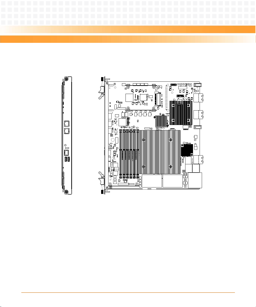
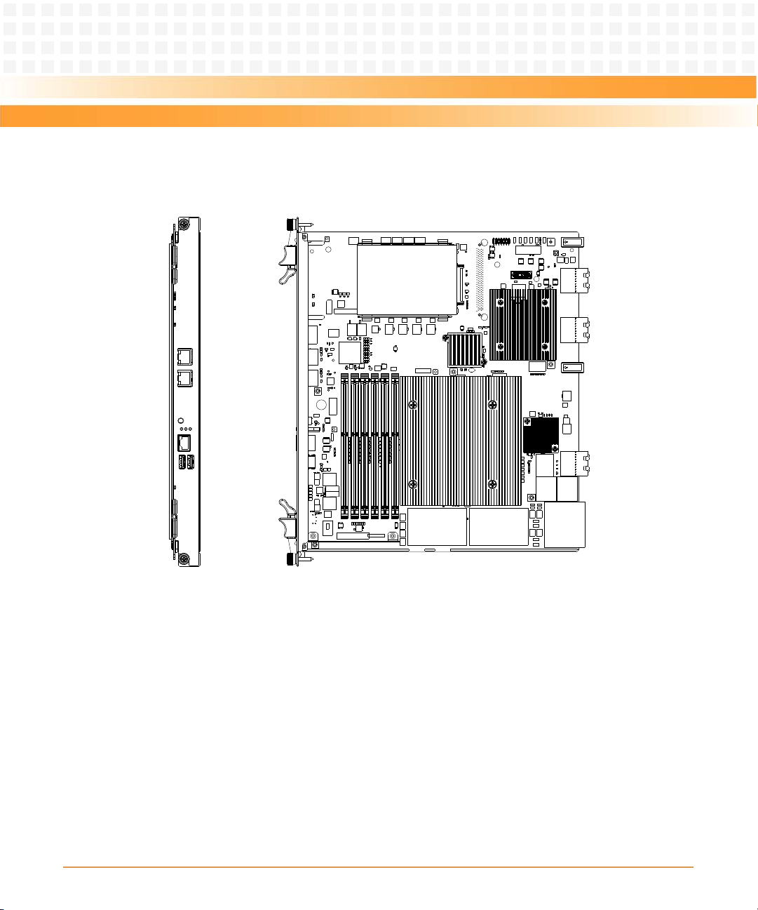
Figure 1-3 Mechanical Layout (without AMC and HDD)
Introduction
ATCA-7368 Installation and Use (6806800M12C)
29
Introduction
Figure 1-4 Mechanical Layout (without AMC/ with HDD)
30
ATCA-7368 Installation and Use (6806800M12C)
 Loading...