

Page 1

ATCA-7350 Control via IPMI
Programmer’s Reference
6806800H29E
August 2011
Page 2

©
2011 Emerson
All rights reserved.
Trademarks
Emerson is a trademark registered in the U.S. Patent and Trademark Office. All other product or service names are the property of
their respective owners.
®
Intel
is a trademark or registered trademark of Intel Corporation or its subsidiaries in the United States and other countries.
™
and all other Java-based marks are trademarks or registered trademarks of Sun Microsystems, Inc. in the U.S. and other
Java
countries.
Microsoft
Microsoft Corporation.
PICMG
PCI Industrial Computer Manufacturers Group.
UNIX
®
, Windows® and Windows Me® are registered trademarks of Microsoft Corporation; and Windows XP™ is a trademark of
®
, CompactPCI®, AdvancedTCA™ and the PICMG, CompactPCI and AdvancedTCA logos are registered trademarks of the
®
is a registered trademark of The Open Group in the United States and other countries.
Notice
While reasonable efforts have been made to assure the accuracy of this document, Emerson assumes no liability resulting from any
omissions in this document, or from the use of the information obtained therein. Emerson reserves the right to revise this document
and to make changes from time to time in the content hereof without obligation of Emerson to notify any person of such revision or
changes.
Electronic versions of this material may be read online, downloaded for personal use, or referenced in another document as a URL to
an Emerson website. The text itself may not be published commercially in print or electronic form, edited, translated, or otherwise
altered without the permission of Emerson,
It is possible that this publication may contain reference to or information about Emerson products (machines and programs),
programming, or services that are not available in your country. Such references or information must not be construed to mean that
Emerson intends to announce such Emerson products, programming, or services in your country.
Limited and Restricted Rights Legend
If the documentation contained herein is supplied, directly or indirectly, to the U.S. Government, the following notice shall apply unless
otherwise agreed to in writing by Emerson.
Use, duplication, or disclosure by the Government is subject to restrictions as set forth in subparagraph (b)(3) of the Rights in Technical
Data clause at DFARS 252.227-7013 (Nov. 1995) and of the Rights in Noncommercial Computer Software and Documentation clause
at DFARS 252.227-7014 (Jun. 1995).
Contact Address
Emerson Network Power - Embedded Computing GmbH
Lilienthalstr. 15
85579 Neubiberg-Munich/Germany
Page 3

Contents
About this Manual . . . . . . . . . . . . . . . . . . . . . . . . . . . . . . . . . . . . . . . . . . . . . . . . . . . . . . . . . . . . . . . . . . . 7
1 Introduction . . . . . . . . . . . . . . . . . . . . . . . . . . . . . . . . . . . . . . . . . . . . . . . . . . . . . . . . . . . . . . . . . . . . 11
1.1 Overview . . . . . . . . . . . . . . . . . . . . . . . . . . . . . . . . . . . . . . . . . . . . . . . . . . . . . . . . . . . . . . . . . . 11
1.2 Feature Description . . . . . . . . . . . . . . . . . . . . . . . . . . . . . . . . . . . . . . . . . . . . . . . . . . . . . . . . . . 11
1.2.1 HPM.1 Specific Firmware Upgrades . . . . . . . . . . . . . . . . . . . . . . . . . . . . . . . . . . . . . . . 11
1.2.1.1 IPMC Firmware Upgrade . . . . . . . . . . . . . . . . . . . . . . . . . . . . . . . . . . . . . . . . 12
1.2.1.2 BIOS Upgrade . . . . . . . . . . . . . . . . . . . . . . . . . . . . . . . . . . . . . . . . . . . . . . . . 12
1.2.1.3 FPGA Upgrade . . . . . . . . . . . . . . . . . . . . . . . . . . . . . . . . . . . . . . . . . . . . . . . . 12
1.2.2 Serial over LAN . . . . . . . . . . . . . . . . . . . . . . . . . . . . . . . . . . . . . . . . . . . . . . . . . . . . . . . 13
1.2.3 Sensors . . . . . . . . . . . . . . . . . . . . . . . . . . . . . . . . . . . . . . . . . . . . . . . . . . . . . . . . . . . . . 13
1.2.4 MAC Address Record. . . . . . . . . . . . . . . . . . . . . . . . . . . . . . . . . . . . . . . . . . . . . . . . . . . 13
1.2.5 Asynchronous Event Notification . . . . . . . . . . . . . . . . . . . . . . . . . . . . . . . . . . . . . . . . . . 13
1.2.6 Graceful Shutdown Timeout . . . . . . . . . . . . . . . . . . . . . . . . . . . . . . . . . . . . . . . . . . . . . . 13
1.2.7 Local System Event Log . . . . . . . . . . . . . . . . . . . . . . . . . . . . . . . . . . . . . . . . . . . . . . . . 14
1.2.8 External Watchdog . . . . . . . . . . . . . . . . . . . . . . . . . . . . . . . . . . . . . . . . . . . . . . . . . . . . . 14
1.2.9 Boot Configuration Parameters . . . . . . . . . . . . . . . . . . . . . . . . . . . . . . . . . . . . . . . . . . . 14
2 Supported Commands . . . . . . . . . . . . . . . . . . . . . . . . . . . . . . . . . . . . . . . . . . . . . . . . . . . . . . . . . . . 15
2.1 Standard IPMI Commands . . . . . . . . . . . . . . . . . . . . . . . . . . . . . . . . . . . . . . . . . . . . . . . . . . . . 15
2.1.1 Global IPMI Commands . . . . . . . . . . . . . . . . . . . . . . . . . . . . . . . . . . . . . . . . . . . . . . . . . 15
2.1.2 System Interface Commands . . . . . . . . . . . . . . . . . . . . . . . . . . . . . . . . . . . . . . . . . . . . . 15
2.1.3 Watchdog Commands . . . . . . . . . . . . . . . . . . . . . . . . . . . . . . . . . . . . . . . . . . . . . . . . . . 16
2.1.4 SEL Device Commands . . . . . . . . . . . . . . . . . . . . . . . . . . . . . . . . . . . . . . . . . . . . . . . . . 16
2.1.5 FRU Inventory Commands . . . . . . . . . . . . . . . . . . . . . . . . . . . . . . . . . . . . . . . . . . . . . . . 17
2.1.6 Sensor Device Commands. . . . . . . . . . . . . . . . . . . . . . . . . . . . . . . . . . . . . . . . . . . . . . . 17
2.1.7 Chassis Device Commands . . . . . . . . . . . . . . . . . . . . . . . . . . . . . . . . . . . . . . . . . . . . . . 18
2.1.7.1 System Boot Options Commands . . . . . . . . . . . . . . . . . . . . . . . . . . . . . . . . . 18
2.1.8 LAN Device Commands . . . . . . . . . . . . . . . . . . . . . . . . . . . . . . . . . . . . . . . . . . . . . . . . . 21
2.2 PICMG 3.0 Commands . . . . . . . . . . . . . . . . . . . . . . . . . . . . . . . . . . . . . . . . . . . . . . . . . . . . . . . 22
2.3 Emerson Specific Commands . . . . . . . . . . . . . . . . . . . . . . . . . . . . . . . . . . . . . . . . . . . . . . . . . . 23
2.3.1 Serial Output Commands . . . . . . . . . . . . . . . . . . . . . . . . . . . . . . . . . . . . . . . . . . . . . . . . 23
2.3.1.1 Set Serial Output Command . . . . . . . . . . . . . . . . . . . . . . . . . . . . . . . . . . . . . 24
2.3.1.2 Get Serial Output Command . . . . . . . . . . . . . . . . . . . . . . . . . . . . . . . . . . . . . 24
3 FRU Information and Sensor Data Records . . . . . . . . . . . . . . . . . . . . . . . . . . . . . . . . . . . . . . . . . . 27
3.1 FRU Information . . . . . . . . . . . . . . . . . . . . . . . . . . . . . . . . . . . . . . . . . . . . . . . . . . . . . . . . . . . . 27
3.2 MAC Address Record . . . . . . . . . . . . . . . . . . . . . . . . . . . . . . . . . . . . . . . . . . . . . . . . . . . . . . . . 27
ATCA-7350 Control via IPMI Programmer’s Reference (6806800H29E)
3
Page 4

Contents
3.3 Sensor Data Records . . . . . . . . . . . . . . . . . . . . . . . . . . . . . . . . . . . . . . . . . . . . . . . . . . . . . . . . 29
4 SOL Module Configuration. . . . . . . . . . . . . . . . . . . . . . . . . . . . . . . . . . . . . . . . . . . . . . . . . . . . . . . . 53
4.1 Introduction . . . . . . . . . . . . . . . . . . . . . . . . . . . . . . . . . . . . . . . . . . . . . . . . . . . . . . . . . . . . . . . . 53
4.2 Configure the SOL . . . . . . . . . . . . . . . . . . . . . . . . . . . . . . . . . . . . . . . . . . . . . . . . . . . . . . . . . . 53
4.3 Enable SOL Load . . . . . . . . . . . . . . . . . . . . . . . . . . . . . . . . . . . . . . . . . . . . . . . . . . . . . . . . . . . 54
4.4 Setup SOL Session . . . . . . . . . . . . . . . . . . . . . . . . . . . . . . . . . . . . . . . . . . . . . . . . . . . . . . . . . . 55
4.5 Query the Configuration of SOL . . . . . . . . . . . . . . . . . . . . . . . . . . . . . . . . . . . . . . . . . . . . . . . . 55
4.6 Configure the SOL Module in OS . . . . . . . . . . . . . . . . . . . . . . . . . . . . . . . . . . . . . . . . . . . . . . . 57
A Related Documentation . . . . . . . . . . . . . . . . . . . . . . . . . . . . . . . . . . . . . . . . . . . . . . . . . . . . . . . . . . 59
A.1 Emerson Network Power - Embedded Computing Documents . . . . . . . . . . . . . . . . . . . . . . . 59
A.2 Related Specifications . . . . . . . . . . . . . . . . . . . . . . . . . . . . . . . . . . . . . . . . . . . . . . . . . . . . . . . 59
4
ATCA-7350 Control via IPMI Programmer’s Reference (6806800H29E)
Page 5

List of Tables
Table 1-1 Features . . . . . . . . . . . . . . . . . . . . . . . . . . . . . . . . . . . . . . . . . . . . . . . . . . . . . . . . . . . . 11
Table 1-2 Sensors . . . . . . . . . . . . . . . . . . . . . . . . . . . . . . . . . . . . . . . . . . . . . . . . . . . . . . . . . . . . 13
Table 2-1 Supported Global IPMI Commands . . . . . . . . . . . . . . . . . . . . . . . . . . . . . . . . . . . . . . . 15
Table 2-2 Supported System Interface Commands . . . . . . . . . . . . . . . . . . . . . . . . . . . . . . . . . . . 15
Table 2-3 Supported Watchdog Commands . . . . . . . . . . . . . . . . . . . . . . . . . . . . . . . . . . . . . . . . 16
Table 2-4 Supported SEL Device Commands . . . . . . . . . . . . . . . . . . . . . . . . . . . . . . . . . . . . . . . 16
Table 2-5 Supported FRU Inventory Commands . . . . . . . . . . . . . . . . . . . . . . . . . . . . . . . . . . . . . 17
Table 2-6 Supported Sensor Device Commands . . . . . . . . . . . . . . . . . . . . . . . . . . . . . . . . . . . . . 17
Table 2-7 Supported Chassis Device Commands . . . . . . . . . . . . . . . . . . . . . . . . . . . . . . . . . . . . 18
Table 2-8 Configurable System Boot Option Parameters . . . . . . . . . . . . . . . . . . . . . . . . . . . . . . . 18
Table 2-9 System Boot Options Parameter #5 . . . . . . . . . . . . . . . . . . . . . . . . . . . . . . . . . . . . . . . 19
Table 2-10 System Boot Options Parameter #96 . . . . . . . . . . . . . . . . . . . . . . . . . . . . . . . . . . . . . . 20
Table 2-11 System Boot Options Parameter #98 . . . . . . . . . . . . . . . . . . . . . . . . . . . . . . . . . . . . . . 20
Table 2-12 System Boot Options Parameter #99 . . . . . . . . . . . . . . . . . . . . . . . . . . . . . . . . . . . . . . 21
Table 2-13 Supported LAN Device Commands . . . . . . . . . . . . . . . . . . . . . . . . . . . . . . . . . . . . . . . 21
Table 2-14 Supported PICMG 3.0 Commands . . . . . . . . . . . . . . . . . . . . . . . . . . . . . . . . . . . . . . . 22
Table 2-15 Serial Output Commands . . . . . . . . . . . . . . . . . . . . . . . . . . . . . . . . . . . . . . . . . . . . . . . 23
Table 2-16 Request Data of Set Serial Output Command . . . . . . . . . . . . . . . . . . . . . . . . . . . . . . . 24
Table 2-17 Response Data of Set Serial Output Command . . . . . . . . . . . . . . . . . . . . . . . . . . . . . 24
Table 2-18 Request Data of Get Serial Output Command . . . . . . . . . . . . . . . . . . . . . . . . . . . . . . . 25
Table 2-19 Response Data of Get Serial Output Command . . . . . . . . . . . . . . . . . . . . . . . . . . . . . 25
Table 3-1 FRU Information . . . . . . . . . . . . . . . . . . . . . . . . . . . . . . . . . . . . . . . . . . . . . . . . . . . . . . 27
Table 3-2 Emerson MAC Address Record . . . . . . . . . . . . . . . . . . . . . . . . . . . . . . . . . . . . . . . . . . 28
Table 3-3 Emerson MAC Address Descriptor . . . . . . . . . . . . . . . . . . . . . . . . . . . . . . . . . . . . . . . 28
Table 3-4 Interface Type Assignments . . . . . . . . . . . . . . . . . . . . . . . . . . . . . . . . . . . . . . . . . . . . . 28
Table 3-5 IPMI Sensors Overview . . . . . . . . . . . . . . . . . . . . . . . . . . . . . . . . . . . . . . . . . . . . . . . . 29
Table 3-6 +12VCC Sensor . . . . . . . . . . . . . . . . . . . . . . . . . . . . . . . . . . . . . . . . . . . . . . . . . . . . . . 30
Table 3-7 +3.3VCC Sensor . . . . . . . . . . . . . . . . . . . . . . . . . . . . . . . . . . . . . . . . . . . . . . . . . . . . . 30
Table 3-8 +3.3VSB Sensor . . . . . . . . . . . . . . . . . . . . . . . . . . . . . . . . . . . . . . . . . . . . . . . . . . . . . . 31
Table 3-9 +5VCC Sensor . . . . . . . . . . . . . . . . . . . . . . . . . . . . . . . . . . . . . . . . . . . . . . . . . . . . . . . 32
Table 3-10 +5VSB Sensor . . . . . . . . . . . . . . . . . . . . . . . . . . . . . . . . . . . . . . . . . . . . . . . . . . . . . . . 33
Table 3-11 -48V Power1 Sensor . . . . . . . . . . . . . . . . . . . . . . . . . . . . . . . . . . . . . . . . . . . . . . . . . . 34
Table 3-12 -48V Power2 Sensor . . . . . . . . . . . . . . . . . . . . . . . . . . . . . . . . . . . . . . . . . . . . . . . . . . 34
Table 3-13 ACPI State Sensor . . . . . . . . . . . . . . . . . . . . . . . . . . . . . . . . . . . . . . . . . . . . . . . . . . . . 35
Table 3-14 BIOS Bank Sensor . . . . . . . . . . . . . . . . . . . . . . . . . . . . . . . . . . . . . . . . . . . . . . . . . . . . 36
Table 3-15 BMC POST ERROR Sensor . . . . . . . . . . . . . . . . . . . . . . . . . . . . . . . . . . . . . . . . . . . . 36
Table 3-16 Boot Errors Sensor . . . . . . . . . . . . . . . . . . . . . . . . . . . . . . . . . . . . . . . . . . . . . . . . . . . . 37
Table 3-17 CPU0 Core Rem Sensor . . . . . . . . . . . . . . . . . . . . . . . . . . . . . . . . . . . . . . . . . . . . . . . 38
Table 3-18 CPU0 Status Sensor . . . . . . . . . . . . . . . . . . . . . . . . . . . . . . . . . . . . . . . . . . . . . . . . . . 39
Table 3-19 CPU1 Core Rem Sensor . . . . . . . . . . . . . . . . . . . . . . . . . . . . . . . . . . . . . . . . . . . . . . . 39
ATCA-7350 Control via IPMI Programmer’s Reference (6806800H29E)
5
Page 6

List of Tables
Table 3-20 CPU1 Status Sensor . . . . . . . . . . . . . . . . . . . . . . . . . . . . . . . . . . . . . . . . . . . . . . . . . . 40
Table 3-21 CPU Inlet Temp Sensor . . . . . . . . . . . . . . . . . . . . . . . . . . . . . . . . . . . . . . . . . . . . . . . . 41
Table 3-22 FBD Inlet Temp Sensor . . . . . . . . . . . . . . . . . . . . . . . . . . . . . . . . . . . . . . . . . . . . . . . . 42
Table 3-23 FRU Hot Swap Sensor . . . . . . . . . . . . . . . . . . . . . . . . . . . . . . . . . . . . . . . . . . . . . . . . . 42
Table 3-24 FW Progress Sensor . . . . . . . . . . . . . . . . . . . . . . . . . . . . . . . . . . . . . . . . . . . . . . . . . . 43
Table 3-25 Handle State Sensor . . . . . . . . . . . . . . . . . . . . . . . . . . . . . . . . . . . . . . . . . . . . . . . . . . 44
Table 3-26 HD Env Temp Sensor . . . . . . . . . . . . . . . . . . . . . . . . . . . . . . . . . . . . . . . . . . . . . . . . . . 44
Table 3-27 IPMB Link State Sensor . . . . . . . . . . . . . . . . . . . . . . . . . . . . . . . . . . . . . . . . . . . . . . . . 45
Table 3-28 Log Disabled Sensor . . . . . . . . . . . . . . . . . . . . . . . . . . . . . . . . . . . . . . . . . . . . . . . . . . 46
Table 3-29 PwrOk Sig. Drop Sensor . . . . . . . . . . . . . . . . . . . . . . . . . . . . . . . . . . . . . . . . . . . . . . . 47
Table 3-30 RTM Handle Sensor . . . . . . . . . . . . . . . . . . . . . . . . . . . . . . . . . . . . . . . . . . . . . . . . . . . 47
Table 3-31 RTM HS Sensor . . . . . . . . . . . . . . . . . . . . . . . . . . . . . . . . . . . . . . . . . . . . . . . . . . . . . . 48
Table 3-32 SYSTEM RESTART Sensor . . . . . . . . . . . . . . . . . . . . . . . . . . . . . . . . . . . . . . . . . . . . . 49
Table 3-33 Ver Change Sensor . . . . . . . . . . . . . . . . . . . . . . . . . . . . . . . . . . . . . . . . . . . . . . . . . . . 49
Table 3-34 Watchdog Sensor . . . . . . . . . . . . . . . . . . . . . . . . . . . . . . . . . . . . . . . . . . . . . . . . . . . . . 50
Table A-1 Related Documentation . . . . . . . . . . . . . . . . . . . . . . . . . . . . . . . . . . . . . . . . . . . . . . . . 59
Table A-2 Related Specifications . . . . . . . . . . . . . . . . . . . . . . . . . . . . . . . . . . . . . . . . . . . . . . . . . 59
6
ATCA-7350 Control via IPMI Programmer’s Reference (6806800H29E)
Page 7

About this Manual
Overview of Contents
This manual is intended for users qualified in electronics or electrical engineering. Users must
have a working understanding of Intelligent Platform Management Interface (IPMI).
It provides information on how to control and monitor the functionality of the ATCA-7350 via
IPMI and contains the following chapters and appendices:
z Chapter 1, Introduction, on page 11 describes the main features of the IPMC firmware.
z Chapter 2, Supported Commands, on page 15 lists all the IPMI1.5 and IPMI2.0 standard
commands supported by the ATCA-7350.
z Chapter 3, FRU Information and Sensor Data Records, on page 27 provides the FRU
information and all the sensor data records.
z Chapter 4, SOL Module Configuration, on page 53 describes how to configure the Serial
over LAN.
z Appendix A, Related Documentation, on page 59 provides links to further ATCA-7350-
related documentation.
Abbreviations
This document uses the following abbreviations:
Abbreviation Definition
ACPI Advanced Configuration and Power Interface
ATCA Advanced Telecom Computing Architecture
BIOS Basic Input/Output System
CMD IPMI Command Specified in Hexadecimal
CPU Central Processing Unit
FBD Fully Buffered DIMM
FPGA Field-Programmable Gate Array
FRU Field Replaceable Unit
FW Firmware
GA General Availability
GUID Global Unique Identifier
HD Hard Disk
IANA Internet Assigned Numbers Authority
IPMB Intelligent Platform Management Bus
ATCA-7350 Control via IPMI Programmer’s Reference (6806800H29E)
7
Page 8

About this Manual
Abbreviation Definition
IPMC Intelligent Platform Management Controller
IPMI Intelligent Platform Management Interface
LAN Local Area Network
LED Light Emitting Diode
LSB Least Significant Bit
LUN Logical Units
MAC Media Access Control
MSB Most Significant Bit
NetFn IPMI Network Function in Hexadecimal
OEM Original Equipment Manufacturer
PICMG PCI Industrial Computer Manufacturers Group
PwrOk Power OK
RTM Rear-Transition Modules
SDR Sensor Data Records
SEL System Event Log
SOL Serial Over LAN
VCC Virtual Channel Connection
VER Version
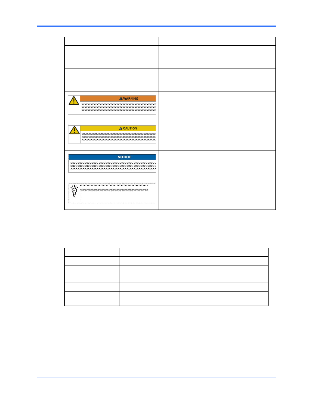
Conventions
The following table describes the conventions used throughout this manual.
Notation Description
0x00000000 Typical notation for hexadecimal numbers (digits are 0
0b0000 Same for binary numbers (digits are 0 and 1)
bold Used to emphasize a word
Screen Used for on-screen output and code related elements or
Courier + Bold Used to characterize user input and to separate it from
Reference Used for references and for table and figure descriptions
File > Exit Notation for selecting a submenu
through F), for example used for addresses and offsets
commands in body text
system output
<text> Notation for variables and keys
[text] Notation for software buttons to click on the screen and
parameter description
... Repeated item for example node 1, node 2, ..., node 12
8
ATCA-7350 Control via IPMI Programmer’s Reference (6806800H29E)
Page 9
About this Manual
Notation Description
.
.
.
.. Ranges, for example: 0..4 means one of the integers
| Logical OR
Omission of information from example/command that is
not necessary at the time being
0,1,2,3, and 4 (used in registers)
Indicates a hazardous situation which, if not avoided,
could result in death or serious injury
Indicates a hazardous situation which, if not avoided,
may result in minor or moderate injury
Indicates a property damage message
Summary of Changes
This manual has been revised and replaces all prior editions.
Part Number Publication Date Description
6806800H29A December 2008 First edition
6806800H29B January 2009 Second edition
6806800H29C January 2009 Third edition
6806800H29D February 2009 Fourth edition
6806800H29E August 2011 Added Table 3-30 on page 47 and Ta b le
Comments and Suggestions
No danger encountered. Pay attention to important
information
3-31 on page 48.
We welcome and appreciate your comments on our documentation. We want to know what you
think about our manuals and how we can make them better.
Mail comments to us by filling out the following online form:
http://www.emersonnetworkpowerembeddedcomputing.com/ > Contact Us > Online Form
ATCA-7350 Control via IPMI Programmer’s Reference (6806800H29E)
9
Page 10

About this Manual
In "Area of Interest" select "Technical Documentation". Be sure to include the title, part number,
and revision of the manual and tell us how you used it.
10
ATCA-7350 Control via IPMI Programmer’s Reference (6806800H29E)
Page 11

Introduction
1.1 Overview
The ATCA-7350 provides an intelligent hardware management system as defined in the
AdvancedTCA Base Specification (PICMG 3.0; AMC.0). This system implements an Intelligent
Peripheral Management Controller (IPMC) based on the proprietary H8S reference design from
American Megatrends Inc.
The ATCA-7350 IPMC supports all standard Intelligent Peripheral Management Interface (IPMI)
commands and provides hardware interfaces for other system managements features such as
hot-swap control, LED control, power control and temperature and voltage monitoring. The
IPMC also supports a Keyboard Controller Style (KCS) based host interface for payload-to-IPMI
communication.
1
In addition, the following features are included:
Table 1-1 Features
Feature Further Details...
Supported for fault tolerant field upgrade
Support for field updates of firmware via the payload
processor interface
Serial over LAN (SOL) Serial over LAN on page 13
Sensor management including, among others, power
good and boot bank supervision sensor
FRU inventory with MAC address record MAC Address Record on page 13
Asynchronous event notification Asynchronous Event Notification on page 13
Graceful shutdown timeout Graceful Shutdown Timeout on page 13
Local system event log (SEL) Local System Event Log on page 14
External watchdog External Watchdog on page 14
BIOS boot configuration via IPMI Boot Configuration Parameters on page 14
IPMC Firmware Upgrade on page 12
Sensors on page 13
Chassis Device Commands on page 18
1.2 Feature Description
Besides its basic functions, the ATCA-7350 provides the features described in this section.
1.2.1 HPM.1 Specific Firmware Upgrades
ATCA-7350 Control via IPMI Programmer’s Reference (6806800H29E)
11
Page 12

Introduction HPM.1 Specific Firmware Upgrades
1.2.1.1 IPMC Firmware Upgrade
The IPMC firmware basically consists of five major parts:
z Boot loader
z Active and Backup IPMI firmware
z Active and Backup SDR data
The boot loader maintains redundant copies of the firmware in the flash memory of the ATCA-
7350. Each time the IPMC firmware is upgraded, the most recent firmware version is kept in
flash memory and the older firmware version is overwritten by the new one. Once the new IPMI
firmware is programmed, the IPMC resets itself to boot from the new image. The boot loader
validates the new IPMC firmware. Provided the IPMC can power up successfully the current
image is made active and the previously active image is made backup. In case of power-up
failures, the boot loader automatically recovers from crisis and boots from the previous image.
The IPMC can be upgraded via KCS and IPMB interface. To ensure that the payload is not
interrupted during IPMC firmware upgrade, the IPMC is storing all operational information (Ekeying, SOL parameters, hot-swap state, last events to be queued, graceful shutdown timeout,
latest pin settings…) in non-volatile storage.
The IPMC firmware is fully HPM.1 compliant. Thus in general also open source tools like
ipmitool can be used for IPMC firmware upgrade. However, we recommend to use the firmware
upgrade tools provided by Emerson (fcu, fuf, or ipmi_upd.sh). To obtain these tools contact your
local sales representative.
The SDR data is hold as a separate component which can be upgraded separately. The IPMC
holds an active and a backup component.
1.2.1.2 BIOS Upgrade
BIOS can either be upgraded via flash based tools provided from Emerson, or via IPMI with the
use of HPM.1 specific protocols. The BIOS firmware is fully implemented as HPM.1 specific
components with an active and an backup image. BIOS upgrade via IPMI is intended to be used
for crisis recovery only. This is because it is much more time consuming than using flash based
routines. Be aware that even when no BIOS boot bank is programmed at all (no boot loader)
crisis recovery via IPMI is always possible.
1.2.1.3 FPGA Upgrade
The FPGA can be upgraded via IPMI also. The IPMC controls an active component and a
backup component for crisis recovery.
12
ATCA-7350 Control via IPMI Programmer’s Reference (6806800H29E)
Page 13

Serial over LAN Introduction
1.2.2 Serial over LAN
Serial over LAN (SOL) is an IPMI v.2.0 defined capability that allows to establish a virtual serial
console connection with the payload over LAN. The serial data of the payload is transferred to
the IPMC. The IPMC generates RMCP+ packets, which are routed to the ethernet controller of
the base interfaces. Be aware that SOL/LAN configuration is only possible if the Ethernet
controller and its payload is fully powered, otherwise the completion code 0xD5 is returned. For
more information on how to use and configure SOL see Chapter 4, SOL Module Configuration,
on page 53.
1.2.3 Sensors
Apart from several voltage and temperature specific sensors (for details refer to Sensor Data
Records on page 29), the IPMC provides the following additional sensors:
Table 1-2 Sensors
Sensor Description
Firmware Progress, and Boot
Error Sensor
The IPMC firmware provides Firmware Progress (Table 3-24 on page
43), and Boot Error (Table 3-16 on page 37) sensors to enable
payload firmware and payload OS to report boot progress and OS
Boot via IPMI event messages.
1.2.4 MAC Address Record
The ATCA-7350 implements an MAC address FRU OEM record. You can retrieve all MAC
addresses of the blade from the FRU information. For more details refer to MAC Address
Record on page 27.
1.2.5 Asynchronous Event Notification
To enable payload applications to be informed about graceful shutdown/reboot requests, the
FRU Activate (Deactivate) and FRU Control (Graceful Reboot) command message is routed as
a LUN2 message to the payload interface.
If the payload application has registered to these commands via the OpenIPMI library, it gets
informed and can take all necessary actions before the payload is gracefully rebooted or shutdown.
1.2.6 Graceful Shutdown Timeout
The IPMI command Set System Boot Options together with the parameter #98 can be used to
persistently specify the timeout for Graceful Shutdown. For more information refer to Chassis
Device Commands on page 18.
ATCA-7350 Control via IPMI Programmer’s Reference (6806800H29E)
13
Page 14

Introduction Local System Event Log
1.2.7 Local System Event Log
The IPMC provides a local system event log (SEL). Thus, event information is stored on-board
the ATCA-7350 as well.
1.2.8 External Watchdog
For crisis recovery purposes the IPMI building block provides an external hardware watchdog.
The IPMI firmware is reset if it does not trigger the watchdog anymore.
1.2.9 Boot Configuration Parameters
The IPMC supports BIOS boot order selection via IPMI partially. Be aware, that in case of the
BIOS boot order is selected via IPMI the boot order displayed in the BIOS menu doesn't reflect
the boot order selected via IPMI. For more information how to set the boot order via IPMI refer
to System Boot Option Commands, parameter #5.
14
ATCA-7350 Control via IPMI Programmer’s Reference (6806800H29E)
Page 15

Supported Commands
2.1 Standard IPMI Commands
The IPMC is fully compliant to the Intelligent Platform Management Interface v.1.5. This section
provides information about the supported IPMI commands.
2.1.1 Global IPMI Commands
The IPMC supports the following global IPMI commands.
Table 2-1 Supported Global IPMI Commands
Command NetFn (Request/Response) CMD Comments
Get Device ID 0x06/0x07 0x01 -
2
Cold Reset 0x06/0x07 0x02 -
Warm Reset 0x06/0x07 0x03 -
Get Self Test Results 0x06/0x07 0x04 -
Get Device GUID 0x06/0x07 0x08 -
2.1.2 System Interface Commands
The system interface commands are supported by blades providing a system interface.
Table 2-2 Supported System Interface Commands
Command NetFn (Request/Response) CMD
Set BMC Global Enables 0x06/0x07 0x2E
Get BMC Global Enables 0x06/0x07 0x2F
Clear Message Flags 0x06/0x07 0x30
Get Message Flags 0x06/0x07 0x31
Get Message 0x06/0x07 0x33
Send Message 0x06/0x07 0x34
Set Channel Access 0x06/0x07 0x40
Get Channel Access 0x06/0x07 0x41
Get Channel Info 0x06/0x07 0x42
Set User Access 0x06/0x07 0x43
Get User Access 0x06/0x07 0x44
Set User Name 0x06/0x07 0x45
ATCA-7350 Control via IPMI Programmer’s Reference (6806800H29E)
15
Page 16

Supported Commands Watchdog Commands
Table 2-2 Supported System Interface Commands (continued)
Command NetFn (Request/Response) CMD
Get User Name 0x06/0x07 0x46
Set User Password 0x06/0x07 0x47
Set User Payload Access 0x06/0x07 0x4C
Get User Payload Access 0x06/0x07 0x4D
Set Channel Security Keys 0x06/0x07 0x5C
2.1.3 Watchdog Commands
The watchdog commands are supported by blades providing a system interface and a
watchdog type 2 sensor.
The pre-timeout option is not supported.
Table 2-3 Supported Watchdog Commands
Command NetFn (Request/Response) CMD
Reset Watchdog Timer 0x06/0x07 0x22
Set Watchdog Timer 0x06/0x07 0x24
Get Watchdog Timer 0x06/0x07 0x25
2.1.4 SEL Device Commands
Table 2-4 Supported SEL Device Commands
Command NetFn (Request/Response) CMD
Get SEL Info 0x0A/0x0B 0x40
Reserve SEL 0x0A/0x0B 0x42
Get SEL Entry 0x0A/0x0B 0x43
Add SEL Entry 0x0A/0x0B 0x44
Clear SEL 0x0A/0x0B 0x47
Get SEL Time 0x0A/0x0B 0x48
Set SEL Time 0x0A/0x0B 0x49
16
ATCA-7350 Control via IPMI Programmer’s Reference (6806800H29E)
Page 17

FRU Inventory Commands Supported Commands
2.1.5 FRU Inventory Commands
Table 2-5 Supported FRU Inventory Commands
Command NetFn (Request/Response) CMD
Get FRU Inventory Area Info 0x0A/0x0B 0x10
Read FRU Data 0x0A/0x0B 0x11
Write FRU Data 0x0A/0x0B 0x12
2.1.6 Sensor Device Commands
Table 2-6 Supported Sensor Device Commands
NetFn
Command
(Request/Response) CMD Comments
Get Device SDR Info 0x04/0x05 0x20 -
Get Device SDR 0x04/0x05 0x21 -
Reserve Device SDR Repository 0x04/0x05 0x22 -
Get Sensor Reading Factors 0x04/0x05 0x23 -
Set Sensor Hysteresis 0x04/0x05 0x24 -
Get Sensor Hysteresis 0x04/0x05 0x25 -
Set Sensor Threshold 0x04/0x05 0x26 -
Get Sensor Threshold 0x04/0x05 0x27 -
Set Sensor Event Enable 0x04/0x05 0x28 -
Get Sensor Event Enable 0x04/0x05 0x29 -
Get Sensor Event Status 0x04/0x05 0x2B -
Get Sensor Reading 0x04/0x05 0x2D -
Get Sensor Type 0x04/0x05 0x2F -
Set Event Receiver 0x04/0x05 0x00 -
Get Event Receiver 0x04/0x05 0x01 -
Platform Event 0x04/0x05 0x02 -
ATCA-7350 Control via IPMI Programmer’s Reference (6806800H29E)
17
Page 18

Supported Commands Chassis Device Commands
2.1.7 Chassis Device Commands
Table 2-7 Supported Chassis Device Commands
Command NetFn (Request/Response) CMD
Set System Boot Options 0x00/0x01 0x08
Get System Boot Options 0x00/0x01 0x09
2.1.7.1 System Boot Options Commands
The IPMI system boot options commands allow you to control the boot process of a blade by
sending boot parameters to the blade’s boot firmware (for example BIOS, U-Boot or VxWorks).
The boot firmware interprets the sent boot parameters and executes the boot process
accordingly. Each boot parameter addresses a particular functionality and consists of a
sequence of one or more bytes. The IPMI specification assigns numbers to boot parameters.
Boot parameters 0 to 7 are standard parameters whose structure and functionality is defined
by the IPMI specification. The boot parameters 96 to 127 are OEM-specific which can be used
for different purposes.
The following table lists which boot properties can be configured and the corresponding boot
parameter number.
Table 2-8 Configurable System Boot Option Parameters
Configurable Boot Property Corresponding Boot Parameter Number
Boot flags 5
Selection between default and backup boot flash as
device to boot from
Selection between default and backup EEPROM as
device where the on-board FPGA loads its configuration
stream from
Timeout for graceful shutdown 98
Write Protection for BIOS boot banks and FRU
information
96
99
18
ATCA-7350 Control via IPMI Programmer’s Reference (6806800H29E)
Page 19

Chassis Device Commands Supported Commands
2.1.7.1.1 System Boot Options Parameter #5
This boot parameter is implemented as specified within the IPMI specification, but not all flags
are supported.
Table 2-9 System Boot Options Parameter #5
Data Byte Description
1 [7] - 1b = boot flags valid. The bit should be set to indicate that valid flag data is
present. This bit may be automatically cleared based on the boot flag valid bit
clearing parameter, above.
[6] - Not supported.
[5] - Not supported
[4:0] - reserved
2 [7] - 1b = CMOS clear
[6] - Not supported
[5:2] - Boot device selector
0000b = No override
0001b = Force PXE
0010b = Force boot from default Hard-drive
0011b = Not supported
0100b = Not supported
0101b = Force boot from default CD/DVD
0110b = Not supported
0111b-1110b = Reserved
1111b = Force boot from Floppy/primary removable media
[1] - 1b = Not supported
[0] - 1b = Not supported
3 Not supported
4 Not supported
5 Reserved
ATCA-7350 Control via IPMI Programmer’s Reference (6806800H29E)
19
Page 20

Supported Commands Chassis Device Commands
2.1.7.1.2 System Boot Options Parameter #96
This boot parameter is an Emerson-specific OEM boot parameter. Its definition is given in the
following table.
Table 2-10 System Boot Options Parameter #96
Boot Option
Parameter Data Description
1 This parameter specifies the processor ID for which the boot option is to be set.
This parameter has to be 0 always for this blade.
2 This parameter is used to select the BIOS boot bank of which the payload shall
boot from:
[7:1] Reserved
[0] Default/backup boot flash selection
There is no Set Selector or Block Selector with this command.
The System Boot Options parameter #96 is non-volatile. Its parameter data remains
preserved after IPMC power cycles and firmware upgrades.
2.1.7.1.3 System Boot Options Parameter #98
This boot parameter is an Emerson-specific OEM parameter.
This timer specifies how long the IPMC waits for the payload to shut down gracefully. If the
payload software does not configure its OpenIPMI library to be notified for graceful shutdown
requests, the IPMC shuts down the payload when the timer expires.
Table 2-11 System Boot Options Parameter #98
Boot Option Parameter
Data Description
1 This parameter specifies the Graceful Shutdown Timeout LSB (given in
100 msec)
2 This parameter specifies the Graceful Shutdown Timeout MSB (given in
100 msec)
20
ATCA-7350 Control via IPMI Programmer’s Reference (6806800H29E)
Page 21

LAN Device Commands Supported Commands
There is no Set Selector or Block Selector with this command.
The System Boot Options parameter #98 is non-volatile. Its parameter data remains
preserved after IPMC power cycles and firmware upgrades.
2.1.7.1.4 System Boot Options #99
This parameter is an Emerson-specific OEM parameter. It is used to enable or disable BIOS
and FRU write protection
Table 2-12 System Boot Options Parameter #99
Boot Option Parameter
Data Description
1 This parameter enables/disables BIOS and FRU write protection:
[7:4] Bios ID (0= Boot Bank A, 1= Boot Bank B, 2= FRU information,
others reserved)
[3:0] write protect enable/disable (0= disable, 1= enable, others reserved)
There is no Set Selector or Block Selector with this command. The Boot Option parameter data
returned with the IPMI command Get System Boot Options provides the write protect status of
the two BIOS flashes and of the FRU information (one byte for each instance).
2.1.8 LAN Device Commands
Table 2-13 Supported LAN Device Commands
Command NetFn (Request/Response) CMD
Set LAN Configuration Parameters 0x0C/0x0D 0x01
Get LAN Configuration Parameters 0x0C/0x0D 0x02
Set SOL Configuration Parameters 0x0C/0x0D 0x21
Get SOL Configuration Parameters 0x0C/0x0D 0x22
ATCA-7350 Control via IPMI Programmer’s Reference (6806800H29E)
21
Page 22

Supported Commands PICMG 3.0 Commands
2.2 PICMG 3.0 Commands
The Emerson IPMC is a fully compliant AdvancedTCA intelligent Platform Management
Controller i.e. it supports all required and mandatory AdvancedTCA commands as defined in
the PICMG 3.0 specifications.
Table 2-14 Supported PICMG 3.0 Commands
NetFn
Command
Get PICMG Properties 0x2C/0x2D 0x00 -
Get Address Info 0x2C/0x2D 0x01 -
FRU Control 0x2C/0x2D 0x04 -
Get FRU LED Properties 0x2C/0x2D 0x05 -
Get FRU LED Color Capabilities 0x2C/0x2D 0x06 -
Set FRU LED State 0x2C/0x2D 0x07 -
Get FRU LED State 0x2C/0x2D 0x08 -
Set IPMB State 0x2C/0x2D 0x09 -
Set FRU Activation Policy 0x2C/0x2D 0x0A -
(Request/Response) CMD Comments
Get FRU Activation Policy 0x2C/0x2D 0x0B -
Set FRU Activation 0x2C/0x2D 0x0C -
Get Device Locator Record ID 0x2C/0x2D 0x0D -
Set Port State 0x2C/0x2D 0x0E -
Get Port State 0x2C/0x2D 0x0F -
Compute Power Properties 0x2C/0x2D 0x10 -
Set Power Level 0x2C/0x2D 0x11 -
Get Power Level 0x2C/0x2D 0x12 -
Get IPMB Link Info 0x2C/0x2D 0x18 -
Set AMC Port State 0x2C/0x2D 0x19 -
Get AMC Port State 0x2C/0x2D 0x1A -
Get FRU Control Capabilities 0x2C/0x2D 0x1E -
Get target upgrade capabilities 0x2C/0x2D 0x2E -
Get component properties 0x2C/0x2D 0x2F -
Abort firmware upgrade 0x2C/0x2D 0x30 -
Initiate upgrade action 0x2C/0x2D 0x31 -
Upload firmware block 0x2C/0x2D 0x32 -
Finish firmware upload 0x2C/0x2D 0x33 -
Get upgrade status 0x2C/0x2D 0x34 -
22
ATCA-7350 Control via IPMI Programmer’s Reference (6806800H29E)
Page 23

Emerson Specific Commands Supported Commands
Table 2-14 Supported PICMG 3.0 Commands (continued)
NetFn
Command
Activate firmware 0x2C/0x2D 0x35 -
Query self-test results 0x2C/0x2D 0x36 -
Query rollback status 0x2C/0x2D 0x37 -
Initiate manual rollback 0x2C/0x2D 0x38 -
The firmware upgrade commands supported by the ATCA-7350 are implemented
according to the PICMG HPM.1 Revision 1.0 specification.
(Request/Response) CMD Comments
2.3 Emerson Specific Commands
The Emerson IPMC supports several commands which are not defined in the IPMI or PICMG
3.0 specification but are introduced by Emerson: serial output commands.
z Before sending any of these commands, the shelf management software must
check whether the receiving IPMI controller supports Emerson specific IPMI
commands, by using the IPMI command 'Get Device ID'. Sending Emerson specific
commands to IPMI controllers which do not support these IPMI commands will lead
to no or undefined results.
z Implementing any of the Emerson specific IPMI commands means that the software
is not portable to other IPMI controllers that do not use the IPMC firmware.
2.3.1 Serial Output Commands
Table 2-15 Serial Output Commands
Command Name NetFn (Request/Response) CMD Description
Set Serial Output 0x2E/0x2F 0x15 See Set Serial Output Command on
Get Serial Output 0x2E/0x2F 0x16 See Get Serial Output Command on
page 24
page 24
ATCA-7350 Control via IPMI Programmer’s Reference (6806800H29E)
23
Page 24

Supported Commands Serial Output Commands
2.3.1.1 Set Serial Output Command
The Set Serial Output command selects the serial port output source for a serial port connector.
2.3.1.1.1 Request Data
The following table lists the request data applicable to the Set Serial Output command.
Table 2-16 Request Data of Set Serial Output Command
Byte Data Field
1 LSB of Emerson IANA Enterprise number. A value of 0xCD has to be used.
2 Second byte of Emerson IANA Enterprise number. A value of 0x65 has to be used.
3 MSB of Emerson IANA Enterprise number. A value of 0x00 has to be used.
4 Serial connector type
0: Face plate connector
All other values are reserved.
5 Serial connector instance number. A sequential number that starts from 0.
6 Serial output selector
0: payload serial console (default 9600 baud)
2: IPMC(default baud rate 115200 baud)
All other values are reserved.
2.3.1.1.2 Response Data
The following table lists the response data applicable to the Set Serial Output command.
Table 2-17 Response Data of Set Serial Output Command
Byte Data Field
1 Completion code
2 LSB of Emerson IANA Enterprise number.
3 Second byte of Emerson IANA Enterprise number.
4 MSB of Emerson IANA Enterprise number.
2.3.1.2 Get Serial Output Command
The Get Serial Output Command provides a way to determine which serial output source goes
to a particular serial port connector.
24
ATCA-7350 Control via IPMI Programmer’s Reference (6806800H29E)
Page 25

Serial Output Commands Supported Commands
2.3.1.2.1 Request Data
The following table lists the request data applicable to the Get Serial Output command.
Table 2-18 Request Data of Get Serial Output Command
Byte Data Field
1 LSB of Emerson IANA Enterprise number. A value of 0xCD has to be used.
2 Second byte of Emerson IANA Enterprise number. A value of 0x65 has to be used.
3 MSB of Emerson IANA Enterprise number. A value of 0x00 has to be used.
4 Serial connector type
0: Face plate connector
All other values are reserved.
5 Serial connector instance number. A sequential number that starts from 0.
2.3.1.2.2 Response Data
The following table lists the response data applicable to the Get Serial Output command.
Table 2-19 Response Data of Get Serial Output Command
Byte Data Field
1 Completion code
2 LSB of Emerson IANA Enterprise number.
3 Second byte of Emerson IANA Enterprise number.
4 MSB of Emerson IANA Enterprise number.
5 Serial output selector
ATCA-7350 Control via IPMI Programmer’s Reference (6806800H29E)
25
Page 26

Supported Commands Serial Output Commands
26
ATCA-7350 Control via IPMI Programmer’s Reference (6806800H29E)
Page 27

FRU Information and Sensor Data Records
3.1 FRU Information
The ATCA-7350 supports FRU according to the PICMG 3.0 ATCA specification. The ATCA7350 supports six FRUs, including:
z FRU0: on the ATCA-7350
z FRU1: RTM-ATCA-7350
z FRU2-FRU3: for daughter cards on the RTM-ATCA-7350
z FRU6: SOL daughter card on the ATCA-7350
FRU0 and FRU1 are managed FRUs, whereas other FRUs are unmanaged ones.
Tab le 3 - 1 shows the FRU data format of RU0-FRU6.
Table 3-1 FRU Information
Area Description Value Access
Board info area Manufacturing
date/time
Board manufacturer EMERSON r/w
According to Platform Management FRU
information Storage Definition v1.0
3
r/w
Board product name ATCA-7350 r/w
Board serial number Defined by Emerson r/w
Board part number Defined by Emerson r/w
Product info area Product manufacturer EMERSON r/w
Product name Specific blade variant name r/w
Product serial
number
Product Version Defined by Emerson r/w
Product part number Defined by Emerson r/w
Multi record area OEM MAC address
record
Board point-to-point
connectivity record
3.2 MAC Address Record
The blade provides one OEM FRU record which contains information about on-board MAC
Defined by Emerson r/w
Emerson record ID 0x01 r/w
PICMG record ID 0x14 r/w
ATCA-7350 Control via IPMI Programmer’s Reference (6806800H29E)
27
Page 28

FRU Information and Sensor Data Records MAC Address Record
addresses. The format of the record is described in the following tables.
Table 3-2 Emerson MAC Address Record
Offset Length Description
0 1 Record Type ID. A value of 0xC0
1 1 End of List/Version
[7] End of List. Set to 01b for the last record
[6:4] Reserved. Write as 0b0000.
[3:0] Record format version. Write as 0x2.
2 1 Record Length
3 1 Record Checksum. Holds the zero checksum of the record
4 1 Header Checksum. Holds the zero checksum of the header.
5 1 LSB of Manufacturer ID. Value is 0xCD
6 1 Second Byte of Manufacturer ID. Value is 0x65
7 1 MSB of Manufacturer ID. Value is 0x00
8 1 Emerson Record ID. Value is 0x01
9 1 Record Format Version. Value is: 0x00
10 1 Number of MAC Address Descriptors (N).
11 N*7 Emerson MAC Address Descriptors
Refer to Table 3-3 on page 28 for definitions of the Emerson MAC Address
Descriptor.
Table 3-3 Emerson MAC Address Descriptor
Offset Length Description
0 1 Interface type
Refer to Table 3-4 on page 28 for interface type assignments.
1 6 MAC Address. First octet comes first.
Table 3-4 Interface Type Assignments
Interface Type Description
0x01 AdvancedTCA base interface or AMC/MicroTCA common options region
0x02 AdvancedTCA fabric interface or AMC/MicroTCA fat pipe region
0x03 Face plate
0x04 AMC/MicroTCA extended fat pipe region
28
ATCA-7350 Control via IPMI Programmer’s Reference (6806800H29E)
Page 29

Sensor Data Records FRU Information and Sensor Data Records
3.3 Sensor Data Records
The sensors available on the ATCA-7350 are shown in the table below.
Table 3-5 IPMI Sensors Overview
Sensor
Sensor Name Sensor Type
+12VCC Voltage 0x07 See Table 3-6 on page 30
+3.3VCC Voltage 0x05 See Table 3-7 on page 30
+3.3VSB Voltage 0x09 See Table 3-8 on page 31
+5VCC Voltage 0x08 See Table 3-9 on page 32
+5VSB Voltage 0x06 See Table 3-10 on page 33
-48V Power1 Power Supply 0x0C See Table 3-11 on page 34
-48V Power2 Power Supply 0x0D See Table 3-12 on page 34
ACPI State System ACPI Power State 0x16 See Table 3-13 on page 35
BIOS Bank Emerson-specific Discrete
Digital
Number Detailed SDR Description
0x19 See Table 3-14 on page 36
BMC POST ERROR Management Subsystem
Health
Boot Errors Boot Error 0x10 See Table 3-16 on page 37
CPU0 Core Rem Temperature 0x13 See Table 3-17 on page 38
CPU0 Status Processor 0x0E See Table 3-18 on page 39
CPU1 Core Rem Temperature 0x14 See Table 3-19 on page 39
CPU1 Status Processor 0x0F See Table 3-20 on page 40
CPU Inlet Temp Temperature 0x01 See Table 3-21 on page 41
FBD Inlet Temp Temperature 0x02 See Table 3-22 on page 42
FRU Hot Swap PICMG 3.0: FRU HotSwap 0x0A See Table 3-23 on page 42
FW Progress System Firmware
Progress
Handle State OEM reserved 0x11 See Table 3-25 on page 44
HD Env Temp Temperature 0x03 See Table 3-26 on page 44
IPMB Link State PICMG 3.0: IPMB Physical
Link
Log Disabled Event Logging Disabled 0x15 See Table 3-28 on page 46
PwrOk Sig. Drop Power Supply 0x12 See Table 3-29 on page 47
RTM Handle OEM reserved 0x30 See Table 3-30 on page 47
RTM HS PICMG 3.0: FRU HotSwap 0x31 See Table 3-31 on page 48
0x1A See Table 3-15 on page 36
0x18 See Table 3-24 on page 43
0x0B See Table 3-27 on page 45
SYSTEM RESTART System Boot Initiated 0x1B See Table 3-32 on page 49
Ver Change Version Change 0x1C See Table 3-33 on page 49
Watchdog Watchdog 2 0x17 See Table 3-34 on page 50
ATCA-7350 Control via IPMI Programmer’s Reference (6806800H29E)
29
Page 30

FRU Information and Sensor Data Records Sensor Data Records
The following tables describe all on-board IPMI sensors in detail.
Table 3-6 +12VCC Sensor
Feature Raw Value Description
Sensor Name +12VCC -
Sensor LUN 0x00 -
Sensor Number 0x07 -
Entity ID 0xA0 PICMG Front Board
Sensor Type 0x02 Voltage
Event/Reading Type 0x01 Threshold
Assertion Event Mask(Byte 15) 0x95 -
Assertion Event Mask(Byte 16) 0x0A -
Deassertion Event Mask(Byte 17) 0x95 -
Deassertion Event Mask(Byte 18) 0x0A -
Threshold Mask(Byte 19) 0x3F -
Threshold Mask(Byte 20) 0x3F -
Base Unit 0x04 Volts
Nominal Reading 0xBF 12.03
Upper non-recoverable threshold 0xE9 14.68
Upper critical threshold 0xE0 14.11
Upper non-critical threshold 0xD6 13.48
Lower non-recoverable threshold 0x94 9.32
Lower critical threshold 0x9D 9.89
Lower non-critical threshold 0xA7 10.52
Rearm mode 0x01 Auto
Hysteresis Support 0x02 Readable and Setable
Threshold Access Support 0x02 Readable and Setable
Event Message Control 0x00 Per Threshold / Discrete State
Reading Definition Analog reading byte Analog sensor reading
Table 3-7 +3.3VCC Sensor
30
Feature Raw Value Description
Sensor Name +3.3VCC -
Sensor LUN 0x00 -
Sensor Number 0x05 -
Entity ID 0xA0 PICMG Front Board
Sensor Type 0x02 Voltage
Event/Reading Type 0x01 Threshold
ATCA-7350 Control via IPMI Programmer’s Reference (6806800H29E)
Page 31

Sensor Data Records FRU Information and Sensor Data Records
Table 3-7 +3.3VCC Sensor (continued)
Feature Raw Value Description
Assertion Event Mask(Byte 15) 0x95 -
Assertion Event Mask(Byte 16) 0x0A -
Deassertion Event Mask(Byte 17) 0x95 -
Deassertion Event Mask(Byte 18) 0x0A -
Threshold Mask(Byte 19) 0x3F -
Threshold Mask(Byte 20) 0x3F -
Base Unit 0x04 Volts
Nominal Reading 0xBF 3.3
Upper non-recoverable threshold 0xD6 3.7
Upper critical threshold 0xD1 3.62
Upper non-critical threshold 0xCC 3.53
Lower non-recoverable threshold 0xA8 2.91
Lower critical threshold 0xAD 2.99
Lower non-critical threshold 0xB1 3.06
Rearm mode 0x01 Auto
Hysteresis Support 0x02 Readable and Setable
Threshold Access Support 0x02 Readable and Setable
Event Message Control 0x00 Per Threshold / Discrete State
Reading Definition Analog reading byte Analog sensor reading
Table 3-8 +3.3VSB Sensor
Feature Raw Value Description
Sensor Name +3.3VSB -
Sensor LUN 0x00 -
Sensor Number 0x09 -
Entity ID 0xA0 PICMG Front Board
Sensor Type 0x02 Voltage
Event/Reading Type 0x01 Threshold
Assertion Event Mask(Byte 15) 0x95 -
Assertion Event Mask(Byte 16) 0x0A -
Deassertion Event Mask(Byte 17) 0x95 -
Deassertion Event Mask(Byte 18) 0x0A -
Threshold Mask(Byte 19) 0x3F -
Threshold Mask(Byte 20) 0x3F -
Base Unit 0x04 Volts
ATCA-7350 Control via IPMI Programmer’s Reference (6806800H29E)
31
Page 32

FRU Information and Sensor Data Records Sensor Data Records
Table 3-8 +3.3VSB Sensor (continued)
Feature Raw Value Description
Nominal Reading 0xC2 3.3
Upper non-recoverable threshold 0xD9 3.69
Upper critical threshold 0xD5 3.62
Upper non-critical threshold 0xD0 3.54
Lower non-recoverable threshold 0xAB 2.91
Lower critical threshold 0xB0 2.99
Lower non-critical threshold 0xB5 3.08
Rearm mode 0x01 Auto
Hysteresis Support 0x02 Readable and Setable
Threshold Access Support 0x02 Readable and Setable
Event Message Control 0x00 Per Threshold / Discrete State
Reading Definition Analog reading byte Analog sensor reading
Table 3-9 +5VCC Sensor
Feature Raw Value Description
Sensor Name +5VCC -
Sensor LUN 0x00 -
Sensor Number 0x08 -
Entity ID 0xA0 PICMG Front Board
Sensor Type 0x02 Voltage
Event/Reading Type 0x01 Threshold
Assertion Event Mask(Byte 15) 0x95 -
Assertion Event Mask(Byte 16) 0x0A -
Deassertion Event Mask(Byte 17) 0x95 -
Deassertion Event Mask(Byte 18) 0x0A -
Threshold Mask(Byte 19) 0x3F -
Threshold Mask(Byte 20) 0x3F -
Base Unit 0x04 Volts
Nominal Reading 0xC3 4.99
Upper non-recoverable threshold 0xDB 5.61
Upper critical threshold 0xD6 5.48
32
Upper non-critical threshold 0xD1 5.35
Lower non-recoverable threshold 0xAC 4.4
Lower critical threshold 0xB1 4.53
Lower non-critical threshold 0xB6 4.66
ATCA-7350 Control via IPMI Programmer’s Reference (6806800H29E)
Page 33

Sensor Data Records FRU Information and Sensor Data Records
Table 3-9 +5VCC Sensor (continued)
Feature Raw Value Description
Rearm mode 0x01 Auto
Hysteresis Support 0x02 Readable and Setable
Threshold Access Support 0x02 Readable and Setable
Event Message Control 0x00 Per Threshold / Discrete State
Reading Definition Analog reading byte Analog sensor reading
Table 3-10 +5VSB Sensor
Feature Raw Value Description
Sensor Name +5VSB -
Sensor LUN 0x00 -
Sensor Number 0x06 -
Entity ID 0xA0 PICMG Front Board
Sensor Type 0x02 Voltage
Event/Reading Type 0x01 Threshold
Assertion Event Mask(Byte 15) 0x95 -
Assertion Event Mask(Byte 16) 0x0A -
Deassertion Event Mask(Byte 17) 0x95 -
Deassertion Event Mask(Byte 18) 0x0A -
Threshold Mask(Byte 19) 0x3F -
Threshold Mask(Byte 20) 0x3F -
Base Unit 0x04 Volts
Nominal Reading 0xC3 4.99
Upper non-recoverable threshold 0xDB 5.61
Upper critical threshold 0xD6 5.48
Upper non-critical threshold 0xD1 5.35
Lower non-recoverable threshold 0xAC 4.4
Lower critical threshold 0xB1 4.53
Lower non-critical threshold 0xB6 4.66
Rearm mode 0x01 Auto
Hysteresis Support 0x02 Readable and Setable
Threshold Access Support 0x02 Readable and Setable
Event Message Control 0x00 Per Threshold / Discrete State
Reading Definition Analog reading byte Analog sensor reading
ATCA-7350 Control via IPMI Programmer’s Reference (6806800H29E)
33
Page 34

FRU Information and Sensor Data Records Sensor Data Records
Table 3-11 -48V Power1 Sensor
Feature Raw Value Description
Sensor Name -48V Power1 -
Sensor LUN 0x00 -
Sensor Number 0x0C -
Entity ID 0xA0 PICMG Front Board
Sensor Type 0x08 Power Supply
Event/Reading Type 0x6F Discrete (sensor-specific)
Assertion Event Mask(Byte 15) 0x03 -
Assertion Event Mask(Byte 16) 0x00 -
Assertion Events - -
- Event Offset: 0 Presence detected
- Event Offset: 1 Power supply failure detected
Deassertion Event Mask(Byte 17) 0x00 -
Deassertion Event Mask(Byte 18) 0x00 -
Threshold Mask(Byte 19) 0x03 -
Threshold Mask(Byte 20) 0x00 -
Base Unit 0x00 (unspecified)
Rearm mode 0x01 Auto
Hysteresis Support 0x00 No Hysteresis or unspecified
Threshold Access Support 0x00 No Thresholds
Event Message Control 0x00 Per Threshold / Discrete State
Reading Definition - -
Table 3-12 -48V Power2 Sensor
Feature Raw Value Description
Sensor Name -48V Power2 -
Sensor LUN 0x00 -
Sensor Number 0x0D -
Entity ID 0xA0 PICMG Front Board
Sensor Type 0x08 Power Supply
34
Event/Reading Type 0x6F Discrete (sensor-specific)
Assertion Event Mask(Byte 15) 0x03 -
Assertion Event Mask(Byte 16) 0x00 -
Assertion Events - -
- Event Offset: 0 Presence detected
- Event Offset: 1 Power supply failure detected
ATCA-7350 Control via IPMI Programmer’s Reference (6806800H29E)
Page 35

Sensor Data Records FRU Information and Sensor Data Records
Table 3-12 -48V Power2 Sensor (continued)
Feature Raw Value Description
Deassertion Event Mask(Byte 17) 0x00 -
Deassertion Event Mask(Byte 18) 0x00 -
Threshold Mask(Byte 19) 0x03 -
Threshold Mask(Byte 20) 0x00 -
Base Unit 0x00 (unspecified)
Rearm mode 0x01 Auto
Hysteresis Support 0x00 No Hysteresis or unspecified
Threshold Access Support 0x00 No Thresholds
Event Message Control 0x00 Per Threshold / Discrete State
Reading Definition - -
Table 3-13 ACPI State Sensor
Feature Raw Value Description
Sensor Name ACPI State -
Sensor LUN 0x00 -
Sensor Number 0x16 -
Entity ID 0xA0 PICMG Front Board
Sensor Type 0x22 System ACPI Power State
Event/Reading Type 0x6F Discrete (sensor-specific)
Assertion Event Mask(Byte 15) 0x40 -
Assertion Event Mask(Byte 16) 0x00 -
Assertion Events - -
- Event Offset: 6 S4/S5 soft-off, particular S4/S5
state cannot be determined
Deassertion Event Mask(Byte 17) 0x00 -
Deassertion Event Mask(Byte 18) 0x00 -
Threshold Mask(Byte 19) 0x40 -
Threshold Mask(Byte 20) 0x00 -
Base Unit 0x00 (unspecified)
Rearm mode 0x01 Auto
Hysteresis Support 0x00 No Hysteresis or unspecified
Threshold Access Support 0x00 No Thresholds
Event Message Control 0x00 Per Threshold / Discrete State
Reading Definition - -
ATCA-7350 Control via IPMI Programmer’s Reference (6806800H29E)
35
Page 36

FRU Information and Sensor Data Records Sensor Data Records
Table 3-14 BIOS Bank Sensor
Feature Raw Value Description
Sensor Name BIOS Bank -
Sensor LUN 0x00 -
Sensor Number 0x19 -
Entity ID 0xA0 PICMG Front Board
Sensor Type 0xD2 Emerson-specific Discrete Digital
Event/Reading Type 0x6F Discrete (sensor-specific)
Assertion Event Mask(Byte 15) 0x0F -
Assertion Event Mask(Byte 16) 0x00 -
Assertion Events - -
- Sensor Offset: 0 Last Boot from BIOS Bank A
- Sensor Offset: 1 Last Boot from BIOS Bank B
Deassertion Event Mask(Byte 17) 0x00 -
Deassertion Event Mask(Byte 18) 0x00 -
Threshold Mask(Byte 19) 0x0F -
Threshold Mask(Byte 20) 0x00 -
Base Unit 0x00 (unspecified)
Rearm mode 0x01 Auto
Hysteresis Support 0x00 No Hysteresis or unspecified
Threshold Access Support 0x00 No Thresholds
Event Message Control 0x00 Per Threshold / Discrete State
Reading Definition - -
Table 3-15 BMC POST ERROR Sensor
Feature Raw Value Description
Sensor Name BMC POST ERROR -
Sensor LUN 0x00 -
Sensor Number 0x1A -
Entity ID 0xA0 PICMG Front Board
Sensor Type 0x28 Management Subsystem Health
36
Event/Reading Type 0x6F Discrete (sensor-specific)
Assertion Event Mask(Byte 15) 0x31 -
Assertion Event Mask(Byte 16) 0x00 -
Assertion Events - -
- Event Offset: 0 Sensor access degraded or
unavailable
- Event Offset: 4 Sensor failure
ATCA-7350 Control via IPMI Programmer’s Reference (6806800H29E)
Page 37

Sensor Data Records FRU Information and Sensor Data Records
Table 3-15 BMC POST ERROR Sensor (continued)
Feature Raw Value Description
- Event Offset: 5 FRU failure
Deassertion Event Mask(Byte 17) 0x31 -
Deassertion Event Mask(Byte 18) 0x00 -
Deassertion Events - -
- Event Offset: 0 Sensor access degraded or
unavailable
- Event Offset: 4 Sensor failure
- Event Offset: 5 FRU failure
Threshold Mask(Byte 19) 0x31 -
Threshold Mask(Byte 20) 0x00 -
Base Unit 0x00 (unspecified)
Rearm mode 0x01 Auto
Hysteresis Support 0x00 No Hysteresis or unspecified
Threshold Access Support 0x00 No Thresholds
Event Message Control 0x00 Per Threshold / Discrete State
Reading Definition - -
Table 3-16 Boot Errors Sensor
Feature Raw Value Description
Sensor Name Boot Errors -
Sensor LUN 0x00 -
Sensor Number 0x10 -
Entity ID 0xA0 PICMG Front Board
Sensor Type 0x1E Boot Error
Event/Reading Type 0x6F Discrete (sensor-specific)
Assertion Event Mask(Byte 15) 0x01 -
Assertion Event Mask(Byte 16) 0x00 -
Assertion Events - -
- Event Offset: 0 No bootable media
Deassertion Event Mask(Byte 17) 0x00 -
Deassertion Event Mask(Byte 18) 0x00 -
Threshold Mask(Byte 19) 0x01 -
Threshold Mask(Byte 20) 0x00 -
Base Unit 0x00 (unspecified)
Rearm mode 0x01 Auto
Hysteresis Support 0x00 No Hysteresis or unspecified
ATCA-7350 Control via IPMI Programmer’s Reference (6806800H29E)
37
Page 38

FRU Information and Sensor Data Records Sensor Data Records
Table 3-16 Boot Errors Sensor (continued)
Feature Raw Value Description
Threshold Access Support 0x00 No Thresholds
Event Message Control 0x00 Per Threshold / Discrete State
Reading Definition - See IPMI 1.5 Specification,
chapter "Sensor Type Codes and
Data"
Table 3-17 CPU0 Core Rem Sensor
Feature Raw Value Description
Sensor Name CPU0 Core Rem -
Sensor LUN 0x00 -
Sensor Number 0x13 -
Entity ID 0x03 -
Sensor Type 0x01 Temperature
Event/Reading Type 0x01 Threshold
Assertion Event Mask(Byte 15) 0x95 -
Assertion Event Mask(Byte 16) 0x0A -
Deassertion Event Mask(Byte 17) 0x95 -
Deassertion Event Mask(Byte 18) 0x0A -
Threshold Mask(Byte 19) 0x3F -
Threshold Mask(Byte 20) 0x3F -
Base Unit 0x01 deg. C
Nominal Reading 0x1E 30
Upper non-recoverable threshold 0x65 101
Upper critical threshold 0x5E 94
Upper non-critical threshold 0x50 80
Lower non-recoverable threshold 0xE0 -32
Lower critical threshold 0xE5 -27
Lower non-critical threshold 0xEA -22
Rearm mode 0x01 Auto
Hysteresis Support 0x02 Readable and Setable
Threshold Access Support 0x02 Readable and Setable
Event Message Control 0x00 Per Threshold / Discrete State
38
Reading Definition Analog reading byte Analog sensor reading
ATCA-7350 Control via IPMI Programmer’s Reference (6806800H29E)
Page 39

Sensor Data Records FRU Information and Sensor Data Records
Table 3-18 CPU0 Status Sensor
Feature Raw Value Description
Sensor Name CPU0 Status -
Sensor LUN 0x00 -
Sensor Number 0x0E -
Entity ID 0x03 -
Sensor Type 0x07 Processor
Event/Reading Type 0x6F Discrete (sensor-specific)
Assertion Event Mask(Byte 15) 0x83 -
Assertion Event Mask(Byte 16) 0x01 -
Assertion Events - -
- Event Offset: 0 Internal error (IERR)
- Event Offset: 1 Thermal Trip
- Event Offset: 7 Processor presence detected
- Event Offset: 8 Processor disabled
Deassertion Event Mask(Byte 17) 0x00 -
Deassertion Event Mask(Byte 18) 0x00 -
Threshold Mask(Byte 19) 0x83 -
Threshold Mask(Byte 20) 0x01 -
Base Unit 0x00 (unspecified)
Rearm mode 0x01 Auto
Hysteresis Support 0x00 No Hysteresis or unspecified
Threshold Access Support 0x00 No Thresholds
Event Message Control 0x00 Per Threshold / Discrete State
Reading Definition - -
Table 3-19 CPU1 Core Rem Sensor
Feature Raw Value Description
Sensor Name CPU1 Core Rem -
Sensor LUN 0x00 -
Sensor Number 0x14 -
Entity ID 0x03 -
Sensor Type 0x01 Temperature
Event/Reading Type 0x01 Threshold
Assertion Event Mask(Byte 15) 0x95 -
Assertion Event Mask(Byte 16) 0x0A -
Deassertion Event Mask(Byte 17) 0x95 -
ATCA-7350 Control via IPMI Programmer’s Reference (6806800H29E)
39
Page 40

FRU Information and Sensor Data Records Sensor Data Records
Table 3-19 CPU1 Core Rem Sensor (continued)
Feature Raw Value Description
Deassertion Event Mask(Byte 18) 0x0A -
Threshold Mask(Byte 19) 0x3F -
Threshold Mask(Byte 20) 0x3F -
Base Unit 0x01 deg. C
Nominal Reading 0x1E 30
Upper non-recoverable threshold 0x65 101
Upper critical threshold 0x5E 94
Upper non-critical threshold 0x50 80
Lower non-recoverable threshold 0xE0 -32
Lower critical threshold 0xE5 -27
Lower non-critical threshold 0xEA -22
Rearm mode 0x01 Auto
Hysteresis Support 0x02 Readable and Setable
Threshold Access Support 0x02 Readable and Setable
Event Message Control 0x00 Per Threshold / Discrete State
Reading Definition Analog reading byte Analog sensor reading
Table 3-20 CPU1 Status Sensor
Feature Raw Value Description
Sensor Name CPU1 Status -
Sensor LUN 0x00 -
Sensor Number 0x0F -
Entity ID 0x03 -
Sensor Type 0x07 Processor
Event/Reading Type 0x6F Discrete (sensor-specific)
Assertion Event Mask(Byte 15) 0x83 -
Assertion Event Mask(Byte 16) 0x01 -
Assertion Events - -
- Event Offset: 0 Internal error (IERR)
40
- Event Offset: 1 Thermal Trip
- Event Offset: 7 Processor presence detected
- Event Offset: 8 Processor disabled
Deassertion Event Mask(Byte 17) 0x00 -
Deassertion Event Mask(Byte 18) 0x00 -
Threshold Mask(Byte 19) 0x83 -
ATCA-7350 Control via IPMI Programmer’s Reference (6806800H29E)
Page 41

Sensor Data Records FRU Information and Sensor Data Records
Table 3-20 CPU1 Status Sensor (continued)
Feature Raw Value Description
Threshold Mask(Byte 20) 0x01 -
Base Unit 0x00 (unspecified)
Rearm mode 0x01 Auto
Hysteresis Support 0x00 No Hysteresis or unspecified
Threshold Access Support 0x00 No Thresholds
Event Message Control 0x00 Per Threshold / Discrete State
Reading Definition - -
Table 3-21 CPU Inlet Temp Sensor
Feature Raw Value Description
Sensor Name CPU Inlet Temp -
Sensor LUN 0x00 -
Sensor Number 0x01 -
Entity ID 0xA0 PICMG Front Board
Sensor Type 0x01 Temperature
Event/Reading Type 0x01 Threshold
Assertion Event Mask(Byte 15) 0x95 -
Assertion Event Mask(Byte 16) 0x0A -
Deassertion Event Mask(Byte 17) 0x95 -
Deassertion Event Mask(Byte 18) 0x0A -
Threshold Mask(Byte 19) 0x3F -
Threshold Mask(Byte 20) 0x3F -
Base Unit 0x01 deg. C
Nominal Reading 0x1E 30
Upper non-recoverable threshold 0x58 88
Upper critical threshold 0x44 68
Upper non-critical threshold 0x37 55
Lower non-recoverable threshold 0xF6 -10
Lower critical threshold 0xFB -5
Lower non-critical threshold 0x05 5
Rearm mode 0x01 Auto
Hysteresis Support 0x02 Readable and Setable
Threshold Access Support 0x02 Readable and Setable
Event Message Control 0x00 Per Threshold / Discrete State
Reading Definition Analog reading byte Analog sensor reading
ATCA-7350 Control via IPMI Programmer’s Reference (6806800H29E)
41
Page 42

FRU Information and Sensor Data Records Sensor Data Records
Table 3-22 FBD Inlet Temp Sensor
Feature Raw Value Description
Sensor Name FBD Inlet Temp -
Sensor LUN 0x00 -
Sensor Number 0x02 -
Entity ID 0xA0 PICMG Front Board
Sensor Type 0x01 Temperature
Event/Reading Type 0x01 Threshold
Assertion Event Mask(Byte 15) 0x95 -
Assertion Event Mask(Byte 16) 0x0A -
Deassertion Event Mask(Byte 17) 0x95 -
Deassertion Event Mask(Byte 18) 0x0A -
Threshold Mask(Byte 19) 0x3F -
Threshold Mask(Byte 20) 0x3F -
Base Unit 0x01 deg. C
Nominal Reading 0x1E 30
Upper non-recoverable threshold 0x5F 95
Upper critical threshold 0x48 72
Upper non-critical threshold 0x3E 62
Lower non-recoverable threshold 0xF6 -10
Lower critical threshold 0xFB -5
Lower non-critical threshold 0x05 5
Rearm mode 0x01 Auto
Hysteresis Support 0x02 Readable and Setable
Threshold Access Support 0x02 Readable and Setable
Event Message Control 0x00 Per Threshold / Discrete State
Reading Definition Analog reading byte Analog sensor reading
Table 3-23 FRU Hot Swap Sensor
Feature Raw Value Description
Sensor Name FRU Hot Swap -
42
Sensor LUN 0x00 -
Sensor Number 0x0A -
Entity ID 0xA0 PICMG Front Board
Sensor Type 0xF0 PICMG 3.0: FRU HotSwap
Event/Reading Type 0x6F Discrete (sensor-specific)
Assertion Event Mask(Byte 15) 0xFF -
ATCA-7350 Control via IPMI Programmer’s Reference (6806800H29E)
Page 43

Sensor Data Records FRU Information and Sensor Data Records
Table 3-23 FRU Hot Swap Sensor (continued)
Feature Raw Value Description
Assertion Event Mask(Byte 16) 0x00 -
Deassertion Event Mask(Byte 17) 0x00 -
Deassertion Event Mask(Byte 18) 0x00 -
Threshold Mask(Byte 19) 0xFF -
Threshold Mask(Byte 20) 0x00 -
Base Unit 0x00 (unspecified)
Rearm mode 0x01 Auto
Hysteresis Support 0x00 No Hysteresis or unspecified
Threshold Access Support 0x00 No Thresholds
Event Message Control 0x00 Per Threshold / Discrete State
Reading Definition - See PICMG 3.0 Specification,
chapter "Reading the FRU HotSwap Sensor"
Table 3-24 FW Progress Sensor
Feature Raw Value Description
Sensor Name FW Progress -
Sensor LUN 0x00 -
Sensor Number 0x18 -
Entity ID 0xA0 PICMG Front Board
Sensor Type 0x0F System Firmware Progress
Event/Reading Type 0x6F Discrete (sensor-specific)
Assertion Event Mask(Byte 15) 0x0F -
Assertion Event Mask(Byte 16) 0x00 -
Assertion Events - -
- Event Offset: 0 System firmware error (POST
Error)
- Event Offset: 1 System firmware hang
- Event Offset: 2 System firmware progress
Deassertion Event Mask(Byte 17) 0x00 -
Deassertion Event Mask(Byte 18) 0x00 -
Threshold Mask(Byte 19) 0x0F -
Threshold Mask(Byte 20) 0x00 -
Base Unit 0x00 (unspecified)
Rearm mode 0x01 Auto
Hysteresis Support 0x00 No Hysteresis or unspecified
ATCA-7350 Control via IPMI Programmer’s Reference (6806800H29E)
43
Page 44

FRU Information and Sensor Data Records Sensor Data Records
Table 3-24 FW Progress Sensor (continued)
Feature Raw Value Description
Threshold Access Support 0x00 No Thresholds
Event Message Control 0x00 Per Threshold / Discrete State
Reading Definition - See IPMI 1.5 Specification,
chapter "Sensor Type Codes and
Data"
Table 3-25 Handle State Sensor
Feature Raw Value Description
Sensor Name Handle State -
Sensor LUN 0x00 -
Sensor Number 0x11 -
Entity ID 0xA0 PICMG Front Board
Sensor Type 0xEB OEM reserved
Event/Reading Type 0x6F Discrete (sensor-specific)
Assertion Event Mask(Byte 15) 0x0F -
Assertion Event Mask(Byte 16) 0x00 -
Assertion Events - -
- Sensor Offset: 0 Handle state ok (both in open/close
state)
- Sensor Offset: 1 Upper handle closed
- Sensor Offset: 2 Lower handle closed
Deassertion Event Mask(Byte 17) 0x00 -
Deassertion Event Mask(Byte 18) 0x00 -
Threshold Mask(Byte 19) 0x0F -
Threshold Mask(Byte 20) 0x00 -
Base Unit 0x00 (unspecified)
Rearm mode 0x01 Auto
Hysteresis Support 0x00 No Hysteresis or unspecified
Threshold Access Support 0x00 No Thresholds
Event Message Control 0x00 Per Threshold / Discrete State
Reading Definition - -
44
Table 3-26 HD Env Temp Sensor
Feature Raw Value Description
Sensor Name HD Env Temp -
Sensor LUN 0x00 -
ATCA-7350 Control via IPMI Programmer’s Reference (6806800H29E)
Page 45

Sensor Data Records FRU Information and Sensor Data Records
Table 3-26 HD Env Temp Sensor (continued)
Feature Raw Value Description
Sensor Number 0x03 -
Entity ID 0xA0 PICMG Front Board
Sensor Type 0x01 Temperature
Event/Reading Type 0x01 Threshold
Assertion Event Mask(Byte 15) 0x95 -
Assertion Event Mask(Byte 16) 0x0A -
Deassertion Event Mask(Byte 17) 0x95 -
Deassertion Event Mask(Byte 18) 0x0A -
Threshold Mask(Byte 19) 0x3F -
Threshold Mask(Byte 20) 0x3F -
Base Unit 0x01 deg. C
Nominal Reading 0x1E 30
Upper non-recoverable threshold 0x5D 93
Upper critical threshold 0x4E 78
Upper non-critical threshold 0x3F 63
Lower non-recoverable threshold 0xF6 -10
Lower critical threshold 0xFB -5
Lower non-critical threshold 0x05 5
Rearm mode 0x01 Auto
Hysteresis Support 0x02 Readable and Setable
Threshold Access Support 0x02 Readable and Setable
Event Message Control 0x00 Per Threshold / Discrete State
Reading Definition Analog reading byte Analog sensor reading
Table 3-27 IPMB Link State Sensor
Feature Raw Value Description
Sensor Name IPMB Link State -
Sensor LUN 0x00 -
Sensor Number 0x0B -
Entity ID 0xA0 PICMG Front Board
Sensor Type 0xF1 PICMG 3.0: IPMB Physical Link
Event/Reading Type 0x6F Discrete (sensor-specific)
Assertion Event Mask(Byte 15) 0x0F -
Assertion Event Mask(Byte 16) 0x00 -
Deassertion Event Mask(Byte 17) 0x00 -
ATCA-7350 Control via IPMI Programmer’s Reference (6806800H29E)
45
Page 46

FRU Information and Sensor Data Records Sensor Data Records
Table 3-27 IPMB Link State Sensor (continued)
Feature Raw Value Description
Deassertion Event Mask(Byte 18) 0x00 -
Threshold Mask(Byte 19) 0x0F -
Threshold Mask(Byte 20) 0x00 -
Base Unit 0x00 (unspecified)
Rearm mode 0x01 Auto
Hysteresis Support 0x00 No Hysteresis or unspecified
Threshold Access Support 0x00 No Thresholds
Event Message Control 0x00 Per Threshold / Discrete State
Reading Definition - See PICMG 3.0 Specification,
c h a p t e r " P h y s i c a l I P M B - 0 S e n s o r s "
Table 3-28 Log Disabled Sensor
Feature Raw Value Description
Sensor Name Log Disabled -
Sensor LUN 0x00 -
Sensor Number 0x15 -
Entity ID 0xA0 PICMG Front Board
Sensor Type 0x10 Event Logging Disabled
Event/Reading Type 0x6F Discrete (sensor-specific)
Assertion Event Mask(Byte 15) 0x3F -
Assertion Event Mask(Byte 16) 0x00 -
Assertion Events - -
- Event Offset: 0 Correctable memory error logging
disabled
- Event Offset: 1 Event 'type' logging disabled.
- Event Offset: 2 Log area reset/cleared
- Event Offset: 3 All event logging disabled
- Event Offset: 4 SEL Full.
- Event Offset: 5 SEL almost full.
Deassertion Event Mask(Byte 17) 0x00 -
Deassertion Event Mask(Byte 18) 0x00 -
Threshold Mask(Byte 19) 0x3F -
46
Threshold Mask(Byte 20) 0x00 -
Base Unit 0x00 (unspecified)
Rearm mode 0x01 Auto
Hysteresis Support 0x00 No Hysteresis or unspecified
ATCA-7350 Control via IPMI Programmer’s Reference (6806800H29E)
Page 47

Sensor Data Records FRU Information and Sensor Data Records
Table 3-28 Log Disabled Sensor (continued)
Feature Raw Value Description
Threshold Access Support 0x00 No Thresholds
Event Message Control 0x00 Per Threshold / Discrete State
Reading Definition - -
Table 3-29 PwrOk Sig. Drop Sensor
Feature Raw Value Description
Sensor Name PwrOk Sig. Drop -
Sensor LUN 0x00 -
Sensor Number 0x12 -
Entity ID 0xA0 PICMG Front Board
Sensor Type 0x08 Power Supply
Event/Reading Type 0x6F Discrete (sensor-specific)
Assertion Event Mask(Byte 15) 0x03 -
Assertion Event Mask(Byte 16) 0x00 -
Assertion Events - -
- Event Offset: 0 Presence detected
- Event Offset: 1 Power supply failure detected
Deassertion Event Mask(Byte 17) 0x00 -
Deassertion Event Mask(Byte 18) 0x00 -
Threshold Mask(Byte 19) 0x03 -
Threshold Mask(Byte 20) 0x00 -
Base Unit 0x00 (unspecified)
Rearm mode 0x01 Auto
Hysteresis Support 0x00 No Hysteresis or unspecified
Threshold Access Support 0x00 No Thresholds
Event Message Control 0x00 Per Threshold / Discrete State
Reading Definition - -
Table 3-30 RTM Handle Sensor
Feature Raw Value Description
Sensor Name RTM Handle -
Sensor LUN 0x00 -
Sensor Number 0x30 -
Entity ID 0xC0 PICMG Rear Transition Module
Sensor Type 0xEB OEM reserved
ATCA-7350 Control via IPMI Programmer’s Reference (6806800H29E)
47
Page 48

FRU Information and Sensor Data Records Sensor Data Records
Table 3-30 RTM Handle Sensor (continued)
Feature Raw Value Description
Event/Reading Type 0x6F Discrete (sensor-specific)
Assertion Event Mask (Byte 15) 0x0F -
Assertion Event Mask (Byte 16) 0x00 -
Assertion Events - -
- Sensor Offset: 0 Handle state ok (both in
open/close state)
- Sensor Offset: 1 Upper handle closed
- Sensor Offset: 2 Lower handle closed
Deassertion Event Mask (Byte 17) 0x00 -
Deassertion Event Mask (Byte 18) 0x00 -
Threshold Mask (Byte 19) 0x0F -
Threshold Mask (Byte 20) 0x00 -
Base Unit 0x00 (unspecified)
Rearm mode 0x01 Auto
Hysteresis Support 0x00 No Hysteresis or unspecified
Threshold Access Support 0x00 No Thresholds
Event Message Control 0x00 Per Threshold / Discrete State
Reading Definition - -
Table 3-31 RTM HS Sensor
Feature Raw Value Description
Sensor Name RTM HS -
Sensor LUN 0x00 -
Sensor Number 0x31 -
Entity ID 0xC0 PICMG Rear Transition Module
Sensor Type 0xF0 PICMG 3.0: FRU HotSwap
Event/Reading Type 0x6F Discrete (sensor-specific)
Assertion Event Mask (Byte 15) 0xFF -
Assertion Event Mask (Byte 16) 0x00 -
48
Deassertion Event Mask (Byte
17)
Deassertion Event Mask (Byte
18)
Threshold Mask (Byte 19) 0xFF -
Threshold Mask (Byte 20) 0x00 -
Base Unit 0x00 (unspecified)
ATCA-7350 Control via IPMI Programmer’s Reference (6806800H29E)
0x00 -
0x00 -
Page 49

Sensor Data Records FRU Information and Sensor Data Records
Table 3-31 RTM HS Sensor (continued)
Feature Raw Value Description
Rearm mode 0x01 Auto
Hysteresis Support 0x00 No Hysteresis or unspecified
Threshold Access Support 0x00 No Thresholds
Event Message Control 0x00 Per Threshold / Discrete State
Reading Definition - See PICMG 3.0 Specification,
chapter "Reading the FRU HotSwap Sensor"
Table 3-32 SYSTEM RESTART Sensor
Feature Raw Value Description
Sensor Name SYSTEM RESTART -
Sensor LUN 0x00 -
Sensor Number 0x1B -
Entity ID 0xA0 PICMG Front Board
Sensor Type 0x1D System Boot Initiated
Event/Reading Type 0x6F Discrete (sensor-specific)
Assertion Event Mask(Byte 15) 0x80 -
Assertion Event Mask(Byte 16) 0x00 -
Assertion Events - -
- Event Offset: 7 System restart
Deassertion Event Mask(Byte 17) 0x00 -
Deassertion Event Mask(Byte 18) 0x00 -
Threshold Mask(Byte 19) 0x80 -
Threshold Mask(Byte 20) 0x00 -
Base Unit 0x00 (unspecified)
Rearm mode 0x01 Auto
Hysteresis Support 0x00 No Hysteresis or unspecified
Threshold Access Support 0x00 No Thresholds
Event Message Control 0x00 Per Threshold / Discrete State
Reading Definition - -
Table 3-33 Ver Change Sensor
Feature Raw Value Description
Sensor Name Ver Change -
Sensor LUN 0x00 -
Sensor Number 0x1C -
ATCA-7350 Control via IPMI Programmer’s Reference (6806800H29E)
49
Page 50

FRU Information and Sensor Data Records Sensor Data Records
Table 3-33 Ver Change Sensor (continued)
Feature Raw Value Description
Entity ID 0xA0 PICMG Front Board
Sensor Type 0x2B Version Change
Event/Reading Type 0x6F Discrete (sensor-specific)
Assertion Event Mask(Byte 15) 0x81 -
Assertion Event Mask(Byte 16) 0x00 -
Assertion Events - -
- Event Offset: 7 Software or firmware change
detected with associated entity was
successful.
Deassertion Event Mask(Byte 17) 0x00 -
Deassertion Event Mask(Byte 18) 0x00 -
Threshold Mask(Byte 19) 0x81 -
Threshold Mask(Byte 20) 0x00 -
Base Unit 0x00 (unspecified)
Rearm mode 0x01 Auto
Hysteresis Support 0x00 No Hysteresis or unspecified
Threshold Access Support 0x00 No Thresholds
Event Message Control 0x00 Per Threshold / Discrete State
Reading Definition - -
Table 3-34 Watchdog Sensor
Feature Raw Value Description
Sensor Name Watchdog -
Sensor LUN 0x00 -
Sensor Number 0x17 -
Entity ID 0xA0 PICMG Front Board
Sensor Type 0x23 Watchdog 2
Event/Reading Type 0x6F Discrete (sensor-specific)
Assertion Event Mask(Byte 15) 0x0F -
Assertion Event Mask(Byte 16) 0x00 -
Assertion Events - -
- Event Offset: 0 Timer expired, status only (no
action, no interrupt)
- Event Offset: 1 Hard reset
50
- Event Offset: 2 Power down
- Event Offset: 3 Power cycle
Deassertion Event Mask(Byte 17) 0x00 -
ATCA-7350 Control via IPMI Programmer’s Reference (6806800H29E)
Page 51

Sensor Data Records FRU Information and Sensor Data Records
Table 3-34 Watchdog Sensor (continued)
Feature Raw Value Description
Deassertion Event Mask(Byte 18) 0x00 -
Threshold Mask(Byte 19) 0x0F -
Threshold Mask(Byte 20) 0x00 -
Base Unit 0x00 (unspecified)
Rearm mode 0x01 Auto
Hysteresis Support 0x00 No Hysteresis or unspecified
Threshold Access Support 0x00 No Thresholds
Event Message Control 0x00 Per Threshold / Discrete State
Reading Definition - See IPMI 1.5 Specification
ATCA-7350 Control via IPMI Programmer’s Reference (6806800H29E)
51
Page 52

FRU Information and Sensor Data Records Sensor Data Records
52
ATCA-7350 Control via IPMI Programmer’s Reference (6806800H29E)
Page 53

SOL Module Configuration
4.1 Introduction
This chapter includes the following sections:
z Configure the SOL
z Enable SOL load
z Setup a SOL session
z Query the configuration of SOL
z Configure the SOL mode in OS
4
4.2 Configure the SOL
Before the configuration, the IPMC has no user or IP address, so you cannot connect to the
IPMC through IPMITOOL. In this case, you need to use IPMI commands through the IPMB
channel of the shelf managers to configure the SOL and set the IPMC.
The IPMB address is the hardware address marked on the shelf multiplied by 2.
Configuring SOL
Perform the following six steps to configure the SOL:
1. Set the IP addresses of the two channels.
Use the command Set LAN Configuration Parameters of IPMI2.0 with Parameter
selector of 3.
See table 23-2 in section 23.1 of the IPMI 2.0 specification.
The value of Parameter selector is 3.
For example, on Emerson shelf manager, set the IP address of channel 1 to
172.17.10.78 and that of channel 2 to 172.18.10.78.
ipmicmd -k "0 90 0 0c 01 01 03 ac 11 0a 4e" smi 0
ipmicmd -k "0 90 0 0c 01 02 03 ac 12 0a 4e" smi 0
ATCA-7350 Control via IPMI Programmer’s Reference (6806800H29E)
53
Page 54

SOL Module Configuration Enable SOL Load
"90" is the IPMB address of the blade.
The IP addresses of the two channels cannot be set to be in the same network
segment. Otherwise, the settings fail.
2. Set the subnet mask of the two channels.
Use the command Set LAN Configuration Parameters of IPMI2.0 with Parameter
selector of 6.
The value of Parameter selector is 6.
See table 23-4 in section 23.2 of the IPMI 2.0 specification.
For example, on Emerson shelf manager, set the subnet masks of both channel 1
and channel 2 to 255.255.0.0.
ipmicmd -k "0 90 0 0c 01 01 06 ff ff 00 00" smi 0
ipmicmd -k "0 90 0 0c 01 02 06 ff ff 00 00" smi 0
"90" is the IPMB address of the blade.
3. Set the user name.
Use the command Set User Name of IPMI2.0.
See table 23-32 in section 23.28 of the IPMI 2.0 specification.
For example, on Emerson shelf manager, set the user name to solusername.
ipmicmd -k "0 90 0 06 45 02 73 6f 6c 75 73 65 72 6e 61 6d 65" smi 0
4. Set the password.
Use the command Set User Password of IPMI2.0.
See table 23-34 in section 23.30 of the IPMI 2.0 specification.
For example, on Emerson shelf manager, set the password to soluserpassword.
ipmicmd -k "0 90 0 06 47 82 02 73 6f 6c 75 73 65 72 70 61 73 73 77 6f 72 64" smi 0
5. Set the user right.
Use the command Set User Access Command of IPMI2.0.
For example, on Emerson shelf manager, set the right of user 2 to Administrator (4).
ipmicmd -k "0 90 0 06 43 f1 02 04 00" smi 0
6. Enable the user.
Use the command Set User Password Command of IPMI2.0.
For example, on Emerson shelf manager, enable user 2.
ipmicmd -k "0 90 0 06 47 82 01" smi 0
4.3 Enable SOL Load
Use the command Set SOL Configuration Parameters of IPMI2.0. The value of Parameter
selector is 1.
See table 26-3 in section 26.2 of the IPMI 2.0 specification.
54
ATCA-7350 Control via IPMI Programmer’s Reference (6806800H29E)
Page 55

Setup SOL Session SOL Module Configuration
The value of Parameter selector is 1.
See table 26-5 in section 26.3 of the IPMI 2.0 specification.
On Emerson shelf manager, enable the SOL of channel 1.
ipmicmd -k "0 90 0 0c 21 01 01 01" smi 0
4.4 Setup SOL Session
After the previous seven steps, you can set up a session or an SOL connection to the IPMC
through IPMITOOL. You can use the commands provided by IPMITOOL to directly configure
the SOL for the IPMC.
If a shelf manager supports automatic configuration through the script, you can use the script
to configure the SOL directly. For example, in the command line of Emerson shelf manager, run
the commands sv_stop and sv_start to restart the script and configure the SOL automatically.
After that, you can use the SOL without configuring and modifying it.
4.5 Query the Configuration of SOL
Querying the configuration of SOL
To query the configurations, do the following:
1. Query the IP address.
Use the command Get LAN Configuration Parameters.
See table 23-3 in section 23.2 of the IPMI 2.0 specification.
The value of Parameter selector is 3.
For example, on Emerson shelf manager, query the IP address of channel 1.
ipmicmd -k "0 90 0 0c 02 01 03 00 00" smi 0
"90" is the IPMB address of the blade.
2. Query the subnet mask.
Use the command Get LAN Configuration Parameters.
The value of Parameter selector is 6.
For example, on Emerson shelf manager, query the subnet mask of channel 1.
ipmicmd -k "0 90 0 0c 02 01 06 00 00" smi 0
3. Query the user name.
Use the command Get User Name.
See table 22-33 in section 22.29 of the IPMI 2.0 specification.
For example, on Emerson shelf manager, query the name of the user 2.
ipmicmd -k "0 90 0 06 46 02 " smi 0
4. Query the channel information.
Use the command Get Channel Access.
ATCA-7350 Control via IPMI Programmer’s Reference (6806800H29E)
55
Page 56

SOL Module Configuration Query the Configuration of SOL
See table 22-27 in section 22.23 of the IPMI 2.0 specification.
For example, on Emerson shelf manager, query the information about channel 1.
ipmicmd -k "0 90 0 06 41 01 40" smi 0
5. Query the user right.
Use the command Get User Access.
See table 22-31 in section 22.27 of the IPMI 2.0 specification.
For example, on Emerson shelf manager, query the right of user 2 in channel 1.
ipmicmd -k "0 90 0 06 44 01 02" smi 0
If a session can be set up between the IPMITOOL and IPMC, you can query the information
through IPMITOOL. For example, query network configuration information.
[b50611@localhost ~]$ ipmitool -I lanplus -L administrator -H 172.17.100.80 -U
solusername -P soluserpassword lan print
Set in Progress : Set Complete
IP Address Source : Static Address
IP Address : 172.17.100.80
Subnet Mask : 255.255.0.0
MAC Address : 00:12:13:14:15:15
SNMP Community String : public
IP Header : TTL=0x40 Flags=0x40 Precedence=0x00 TOS=0x10
IPMC ARP Control : ARP Responses Enabled, Gratuitous ARP Enabled
Gratituous ARP Intrvl : 2.0 seconds
Default Gateway IP : 172.17.166.55
RMCP+ Cipher Suites :
Cipher Suite Priv Max : uuuaXXXXXXXXXXX
: X=Cipher Suite Unused
: c=CALLBACK
: u=USER
: o=OPERATOR
56
: a=ADMIN
: O=OEM
For details on how to query and set by IPMITOOL, refer to the documents related to IPMITOOL.
ATCA-7350 Control via IPMI Programmer’s Reference (6806800H29E)
Page 57

Configure the SOL Module in OS SOL Module Configuration
4.6 Configure the SOL Module in OS
All the configurations and the queries example above are carried out on the shelf manager of
Emerson. If you want to do it in OS with standard IPMI tools by sending the IPMI command to
the IPMC through KCS, some parameters of the command should be modified.
For example, we set the IP address of channel 1:
Emerson shelf manager:
ipmicmd -k "0 90 0 0c 01 01 03 ac 11 0a 4e" smi 0
Linux OS:
ipmicmd -k "f 0 0c 01 01 03 ac 11 0a 4e" smi 0
The identification section is different while the other parameters are the same, where "f" is the
sending address of local KCS, "0" is the logic unit number.
ATCA-7350 Control via IPMI Programmer’s Reference (6806800H29E)
57
Page 58

SOL Module Configuration Configure the SOL Module in OS
58
ATCA-7350 Control via IPMI Programmer’s Reference (6806800H29E)
Page 59

A Related Documentation
A
A.1 Emerson Network Power - Embedded Computing
Documents
The Emerson Network Power - Embedded Computing publications listed below are referenced
in this manual. You can obtain electronic copies of Emerson Network Power - Embedded
Computing publications by contacting your local Emerson sales office. For documentation of
final released (GA) products, you can also visit the following website:
http://www.emersonnetworkpowerembeddedcomputing.com > Resource Center > Technical
Documentation Search. This site provides the most up-to-date copies of Emerson Network
Power - Embedded Computing product documentation.
Table A-1 Related Documentation
Document Title Publication Number
ATCA-7150 Installation and Use 6806800E88
ATCA-7350 Installation and Use 6806800H59
RTM-ATCA-7350 Installation and Use 6806800H30
ATCA-7150: Control via IPMI Programmer’s Reference 6806800E85
RTM-ATCA-7150 Installation and Use 6806800E87
ATCA-7X50-MEM Installation Information 6806800E27
ATCA-7X50-HDDx-SAS/SATA Installation Information 6806800E28
MEZC-RTM-7150-GE Installation Information 6806800F89
MEZC-RTM-7150-FC Installation Information 6806800F90
A.2 Related Specifications
For additional information, refer to the following table for related specifications. As an additional
help, a source for the listed document is provided. Please note that, while these sources have
been verified, the information is subject to change without notice.
Table A-2 Related Specifications
Item Documentation
1 Intelligent Platform Management Interface Specification v1.5
2 Intelligent Platform Management Interface Specification Second Generation v2.0
3 PICMG 3.0 Revision 1.0 AdvancedTCA Base Specification
ATCA-7350 Control via IPMI Programmer’s Reference (6806800H29E)
59
Page 60

Related Documentation Related Specifications
60
ATCA-7350 Control via IPMI Programmer’s Reference (6806800H29E)
 Loading...