

Emerson Asco Sentronic LP 617 Series Installation Manual
Sentronic
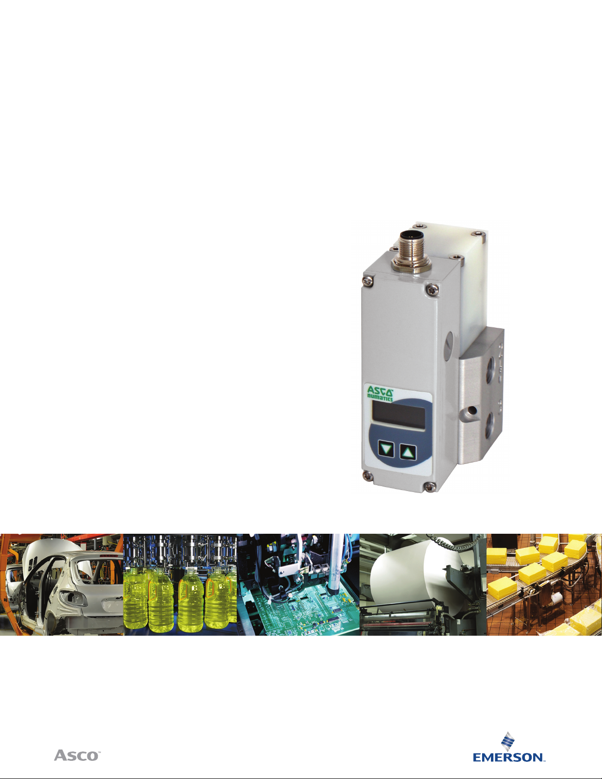
617 Series IO-Link CLASS A with Display and Controls
Installation Manual
LP
IO-Link CLASS A | 617 Series

ESD
Table of Contents
!
Sentronic
Description 2
How To Order 2
Operating Elements 3
Manual Pressure Adjustment 3
Operating Modes 3
Electrical Connection 4
Analog Target Value - Output Pressure 5
Pneumatic Connection 6
Information on the Factory Settings 6
Technical Characteristics 7
Fluid Characteristics 7
Key Values 7
Care and Maintenance 8
Dimensions and Weights 9
LP
This product contains electronic components sensitive to electrostatic
CAUTION
OBSERVE PRECAUTIONS
FOR HANDLING
ELECTROSTATIC SENSITIVE
DEVICES
CAUTION! Dangerous operating conditions may occur when using the programming interface on the valve as the valve may
possibly not react to the analog setpoint any more.
Provide for protection against uncontrolled movement of equipment when putting the valve into operation and before making
any modifi cations to the valve settings.
We herewith declare that the version of the product described in this installation manual is intended to be incorporated into or assembled
with other machinery and that it must not be put into service until the machinery into which it is to be incorporated has been declared in
conformity with the provisions of Council Directive 2006/42/EC.
Handling, assembly and putting into service and all settings and adjustments must be done by qualifi ed, authorised personnel only.
This pr oduct compli es with the ess ential req uirements of t he EMC Direc tive 2014/30/EU and it s amendment s. It is CE-app roved.
A separate Declaration of Conformity is available on request.
Please provide ordering code and serial numbers of products concerned.
The information in this manual is subject to change without notice.
In no event shall ASCO NUMATICS be liable for technical or editorial errors or omissions. Neither is any liability assumed for accidental
or consequential damages arising out of or in connection with the supply or use of the information contained herein.
THIS MANUAL CONTAINS INFORMATION PROTECTED BY COPYRIGHT. NO PART OF THIS DOCUMENT MAY BE PHOTOCOPIED
OR REPRODUCED IN ANY FORM OR MANNER WHATSOEVER WITHOUT PRIOR WRITTEN PERMISSION FROM ASCO NUMATICS.
COPYRIGHT © 2016 - ASCO NUMATICS - All rights reserved.
discharge. An electrostatic discharge generated by a person or object
coming in contact with the electrical components can damage or
destroy the product.
To avoid the risk of electrostatic discharge, please observe the handling
precautions and recommendations contained in standard EN 100015-1.
Do not connect or disconnect the device while it is energised.
NOTICE

SERIES
617
INSTALLATION
ASCO NUMATICS™
MANUAL
Description
The SentronicLP valve operates with pulsed pilot valves which change the pressure in a control chamber.
A downstream flow amplifier (pressure booster) converts the control pressure into an output pressure. The output
pressure is measured by a pressure sensor and fed to the integrated digital control circuit.
SentronicLP is particularly suitable for pressure control procedures where a constant pressure is required with
different flow rates, such as air dosing via nozzles or turbine rotation speed control.
Using the available DaS software (Data Acquisition Software), the valve can be adapted to the application if
necessary.
• The pressure connections and the air vent connections are designed in the same size, which results in short
response times both for increasing the pressure and for reducing the pressure.
• Digital pressure control in a closed circuit: An internal pressure sensor measures the output pressure. The
output pressure is adjusted in real time.
• The control parameters can be changed with the additional DaS software. The variability of the parameters
used by the valve is ensured by the DaS software. This flexibility makes it possible to adapt the valve to a very
wide range of applications and to optimize the response time and the precision of the valve and prevent it from
overshooting.
• After determining the optimum parameters, these can be saved for personal use in a project file, which can be
sent into our Product Support Department for future series production.
How to Order
8 617 A 4 2 2 1 0 A00 PB
Threaded Connection
G = ISO 228 (BSPP)
8 = NPT
Product Series
617
Revision
A = Initial release
Size
0 = Manifold Version + pressure hold (DN4)
4 = 1/4 + pressure hold (DN4)
6 = 3/8 + pressure hold (DN8)
8 = 1/2 + pressure hold (DN15)
Setpoint
8 = IO-Link Class A
1
See Accessories for individual subbases for this Manifold Ver sion
2
No Digital In possible
1
Pressure Range
Max. Inlet
Pressure
PA = 0 – 50 psi 90 psi
PB = 0 – 100 psi 140 psi
PC = 0 – 150 psi 190 psi
Options
A00 = Standard
A07 = Oxygen clean
Display w/Keys
0 = with display
1 = without display
Output
1 = standard
FeedbackType
6 = IO-Link Class A
2
2
Visit our website at ASCO.com or contact us at (800) 972-2726

ASCO NUMATICS™
Operating Elements
SERIES
617
INSTALLATION
MANUAL
1
6
5
7
1 Power supply, M12 plug
2 Pressure output
3 Protective ground - M4 connector
4 Exhaust
5 Pressure supply
6 LC display
7 Control keys
8 Mounting hole
2
3
8
4
Manual Pressure Adjustment
(Manual Operation - Only for version with a display)
If the supply voltage is cut off, after a reconnection of the supply voltage and by pressing the two arrow keys below
the display at the same time, the pressure regulator will change to “Manual operation” mode. This operating mode is
indicated in the display by the letters “HND”.
The letters “HND” in the display will disappear after the arrow keys are released. The output pressure is shown on the
display, followed by the letters “HND” at the top right of the display.
Using the arrow keys, the output pressure can be changed (left arrow key or arrow pointing down => reduce the
output pressure, right arrow key or arrow pointing up => increase the output pressure).
This operating mode can be exited by pressing both arrow keys at the same time or by briefly cutting off the supply
voltage.
Operating Modes
Shutoff:
If the setpoint is set to less than 0.5%, the air will be released from the valve and the current supplied to the exhaust
valve will be switched off after 10 seconds.
Over temperature:
If the internal control electronics reach a temperature above 100°C, the control function will be restricted in order to
prevent any more overheating.
Visit our website at ASCO.com or contact us at (800) 972-2726
3
 Loading...