

Page 1

User Guide
Affinity
Model sizes 1 to 6
Building Automation HVAC/R
drive
Part Number: 0474-0000-05
Issue: 5
www.controltechniques.com
Page 2

General Information
The manufacturer accepts no liability for any consequences resulting from inappropriate, negligent or incorrect
installation or adjustment of the optional operating parameters of the equipment or from mismatching the variable speed
drive with the motor.
The contents of this guide are believed to be correct at the time of printing. In the interests of a commitment to a policy
of continuous development and improvement, the manufacturer reserves the right to change the specification of the
product or its performance, or the contents of the guide, without notice.
All rights reserved. No parts of this guide may be reproduced or transmitted in any form or by any means, electrical or
mechanical including photocopying, recording or by an information storage or retrieval system, without permission in
writing from the publisher.
Drive software version
This product is supplied with the latest software version. If this drive is to be connected to an existing system or machine,
all drive software versions should be verified to confirm the same functionality as drives of the same model already
present. This may also apply to drives returned from a Control Techniques Service Centre or Repair Centre. If there is
any doubt please contact the supplier of the product.
The software version of the drive can be checked by looking at Pr 11.29 and Pr 11.34. This takes the form of xx.yy.zz
where Pr 11.29 displays xx.yy and Pr 11.34 displays zz. (e.g. for software version 01.01.00, Pr 11.29 = 1.01 and Pr 11.34
displays 0).
The software version of the Building Automation interface can be checked by looking at Pr 17.02 and Pr 17.51. The
software version takes the form of xx.yy.zz, where Pr 17.02 displays xx.yy and Pr 17.51 displays zz.
Environmental statement
Control Techniques is committed to minimising the environmental impacts of its manufacturing operations and of its
products throughout their life cycle. To this end, we operate an Environmental Management System (EMS) which is
certified to the International Standard ISO 14001. Further information on the EMS, our Environmental Policy and other
relevant information is available on request, or can be found at www.greendrives.com.
The electronic variable-speed drives manufactured by Control Techniques have the potential to save energy and
(through increased machine/process efficiency) reduce raw material consumption and scrap throughout their long
working lifetime. In typical applications, these positive environmental effects far outweigh the negative impacts of product
manufacture and end-of-life disposal.
Nevertheless, when the products eventually reach the end of their useful life, they must not be discarded but should
instead be recycled by a specialist recycler of electronic equipment. Recyclers will find the products easy to dismantle
into their major component parts for efficient recycling. Many parts snap together and can be separated without the use
of tools, whilst other parts are secured with conventional fasteners. Virtually all parts of the product are suitable for
recycling.
Product packaging is of good quality and can be re-used. Large products are packed in wooden crates, while smaller
products come in strong cardboard cartons which themselves have a high recycled fibre content. If not re-used, these
containers can be recycled. Polythene, used on the protective film and bags for wrapping product, can be recycled in the
same way. Control Techniques' packaging strategy prefers easily-recyclable materials of low environmental impact, and
regular reviews identify opportunities for improvement.
When preparing to recycle or dispose of any product or packaging, please observe local legislation and best practice.
REACH legislation
EC Regulation 1907/2006 on the Registration, Evaluation, Authorisation and restriction of Chemicals (REACH) requires
the supplier of an article to inform the recipient if it contains more than a specified proportion of any substance which is
considered by the European Chemicals Agency (ECHA) to be a Substance of Very High Concern (SVHC) and is
therefore listed by them as a candidate for compulsory authorisation.
For current information on how this requirement applies in relation to specific Control Techniques products, please
approach your usual contact in the first instance. Control Techniques position statement can be viewed at:
http://www.controltechniques.com/REACH
Copyright © May 2011 Control Techniques Ltd.
Issue Number: 5
Software: 01.06.00 onwards
Page 3

Contents
1 Safety information .................................7
1.1 Warnings, cautions and notes ...............................7
1.2 Electrical safety - general warning ........................7
1.3 System design and safety of personnel ................7
1.4 Environmental limits ..............................................7
1.5 Access ..................................................................7
1.6 Fire protection .......................................................7
1.7 Compliance with regulations .................................7
1.8 Motor .....................................................................7
1.9 Mechanical brake control ......................................7
1.10 Adjusting parameters ............................................7
1.11 Electrical installation .............................................8
2 Product information ..............................9
2.1 Introduction ...........................................................9
2.2 Drive types ..........................................................10
2.3 Ratings ................................................................10
2.4 Model number .....................................................14
2.5 Operating modes ................................................14
2.6 Drive features ......................................................15
2.7 Nameplate description ........................................16
2.8 Options ................................................................17
2.9 Items supplied with the drive ...............................19
3 Mechanical installation .......................20
3.1 Safety information ...............................................20
3.2 Planning the installation ......................................20
3.3 Terminal cover removal ......................................22
3.4 Solutions Module / keypad installation /
removal ...............................................................29
3.5 Mounting methods ..............................................31
3.6 Enclosure for standard drives .............................48
3.7 Enclosure design and drive ambient
temperature..........................................................49
3.8 Enclosing standard drive for high environmental
protection ............................................................50
3.9 External EMC filter for standard drives ..............54
3.10 Electrical terminals ..............................................62
3.11 Routine maintenance ..........................................63
4 Electrical installation ..........................66
4.1 Power connections ..............................................66
4.2 AC supply requirements ......................................69
4.3 Auxiliary power supply ........................................70
4.4 Supplying the drive with DC / DC bus
paralleling ............................................................71
4.5 Fan connections ..................................................71
4.6 Control 24Vdc supply ..........................................71
4.7 Ratings ................................................................71
4.8 Output circuit and motor protection .....................74
4.9 Braking ................................................................76
4.10 Ground leakage ..................................................78
4.11 EMC (Electromagnetic compatibility) ..................78
4.12 PC communications connections ........................87
4.13 Terminal connections ..........................................88
4.14 Building automation network connections ...........92
4.15 Heatsink fan supply connections (size 4 to 6) .....92
5 Getting started..................................... 93
5.1 Understanding the display ..................................93
5.2 Keypad operation ................................................93
5.3 Menu structure ....................................................94
5.4 Menu 0 ................................................................95
5.5 Advanced menus ................................................95
5.6 Changing the operating mode .............................97
5.7 Changing the keypad mode ................................97
5.8 Saving parameters ..............................................97
5.9 Restoring parameter defaults ..............................97
5.10 Parameter access level and security ..................97
5.11 Displaying parameters with non-default
values only ..........................................................99
5.12 Displaying destination parameters only ..............99
5.13 Communications .................................................99
6 Basic parameters ..............................102
6.1 Single line descriptions .....................................102
6.2 Full descriptions ................................................106
7 Running the motor ............................115
7.1 Quick start Connections ....................................115
7.2 Changing the operating mode ...........................115
7.3 Changing keypad mode ....................................115
7.4 Quick Start commissioning/start-up ..................118
8 Optimization .......................................121
8.1 Motor map parameters ......................................121
8.2 Current limits .....................................................127
8.3 Motor thermal protection ...................................127
8.4 Switching frequency ..........................................128
8.5 High speed operation ........................................128
Affinity User Guide 3
Issue Number: 5 www.controltechniques.com
Page 4

9 SMARTCARD operation ....................129
9.1 Introduction .......................................................129
9.2 Transferring data ...............................................130
9.3 Data block header information ..........................131
9.4 SMARTCARD parameters ................................132
9.5 SMARTCARD trips ............................................133
10 PC tools ..............................................135
10.1 CTSoft ...............................................................135
10.2 Onboard PLC and SYPTLite .............................135
10.3 CT Energy Savings Estimator ...........................137
11 Advanced parameters .......................139
11.1 Menu 1: Frequency / speed reference ..............146
11.2 Menu 2: Ramps .................................................150
11.3 Menu 3: Speed feedback and speed control .....153
11.4 Menu 4: Torque and current control ..................156
11.5 Menu 5: Motor control .......................................159
11.6 Menu 6: Sequencer and clock ...........................163
11.7 Menu 7: Analog I/O ...........................................165
11.8 Menu 8: Digital I/O ............................................168
11.9 Menu 9: Programmable logic, motorized pot,
binary sum and timers .......................................171
11.10 Menu 10: Status and trips .................................175
11.11 Menu 11: General drive set-up ..........................177
11.12 Menu 12: Threshold detectors, variable
selectors and brake control function .................178
11.13 Menu 14: User PID controller ............................186
11.14 Menus 15 and 16: Solutions Module set-up ......193
11.15 Menu 17: Building Automation Network ............212
11.16 Menu 18: Application menu 1 ............................212
11.17 Menu 19: Application menu 2 ............................212
11.18 Menu 20: Application menu 3 ............................212
11.19 Menu 21: Second motor parameters .................213
11.20 Menu 22: Additional Menu 0 set-up ..................214
11.21 Advanced features ............................................215
Index .................................................. 270
12 Technical data ....................................228
12.1 Drive technical data ...........................................228
12.2 Optional external EMC filters ............................246
13 Diagnostics ........................................250
13.1 Trip indications ..................................................250
13.2 Alarm indications ...............................................262
13.3 Status indications ..............................................262
13.4 Displaying the trip history ..................................263
13.5 Behavior of the drive when tripped ....................263
14 UL listing information .......................264
14.1 Common UL information ...................................264
14.2 Power dependant UL information ......................264
14.3 AC supply specification .....................................264
14.4 Maximum continuous output current .................264
14.5 Safety label .......................................................265
14.6 UL listed accessories ........................................265
List of figures .................................... 266
List of tables ..................................... 268
4 Affinity User Guide
www.controltechniques.com Issue Number: 5
Page 5

Control Techniques Ltd
The Gro
Newtown
Powys
UK
SY16 3BE
Declaration of Conformity (Size 1 to 5)
BA1201 BA1202 BA1203 BA1204
BA2201 BA2202 BA2203
BA3201 BA3202
BA4201 BA4202 BA4203
BA5201 BA5202
BA1401 BA1402 BA1403 BA1404 BA1405 BA1406
BA2401 BA2402 BA2403
BA3401 BA3402 BA3403
BA4401 BA4402 BA4403
BA5401 BA5402
BA3501 BA3502 BA3503 BA3504 BA3505 BA3506
BA3507
BA4601 BA4602 BA4603 BA4604 BA4605 BA4606
BA5601 BA5602
The AC variable speed drive products listed above have been designed
and manufactured in accordance with the following European
harmonized standards:
These products comply with the Low Voltage Directive 2006/95/EC and
the Electromagnetic Compatibility Directive 2004/108/EC.
T.Alexander
Vice President, Technology
Newtown
Date: 14th July 2009
These electronic drive products are intended to be used with
appropriate motors, controllers, electrical protection components
and other equipment to form complete end products or systems.
Compliance with safety and EMC regulations depends upon
installing and configuring drives correctly, including using the
specified input filters. The drives must be installed only by
professional assemblers who are familiar with requirements for
safety and EMC. The assembler is responsible for ensuring that the
end product or system complies with all the relevant laws in the
country where it is to be used. Refer to the User Guide. An EMC
Data Sheet is also available giving detailed EMC information.
EN 61800-5-1:2007
EN 61800-3:2004
EN 61000-6-2:2005
EN 61000-6-4:2007
Adjustable speed electrical power drive
systems - safety requirements - electrical,
thermal and energy
Adjustable speed electrical power drive
systems. EMC product standard including
specific test methods
Electromagnetic compatibility (EMC).
Generic standards. Immunity standard for
industrial environments
Electromagnetic compatibility (EMC).
Generic standards. Emission standard for
industrial environments
Affinity User Guide 5
Issue Number: 5 www.controltechniques.com
Page 6

Safety
Information
Product
Information
Mechanical
Installation
Control Techniques Ltd
The Gro
Newtown
Powys
UK
SY16 3BE
Electrical
Installation
Getting
Star ted
Basic
parameters
Running
the motor
Optimization
SMARTCARD
operation
PC tools
Declaration of Conformity (Size 6)
Advanced
parameters
Technical
Data
Diagnostics
UL Listing
Information
BA6401 BA6402
BA6601 BA6602
The AC variable speed drive products listed above have been designed
and manufactured in accordance with the following European
harmonized standards:
Adjustable speed electrical power drive
EN 61800-5-1:2007
systems - safety requirements - electrical,
thermal and energy
Adjustable speed electrical power drive
EN 61800-3:2004
systems. EMC product standard including
specific test methods
Electromagnetic compatibility (EMC). Generic
EN 61000-6-2:2005
standards. Immunity standard for industrial
environments
These products comply with the Low Voltage Directive 2006/95/EC and
the Electromagnetic Compatibility Directive 2004/108/EC.
T.Alexander
Vice President, Technology
Newtown
Date: 14th July 2009
These electronic drive products are intended to be used with
appropriate motors, controllers, electrical protection components
and other equipment to form complete end products or systems.
Compliance with safety and EMC regulations depends upon
installing and configuring drives correctly, including using the
specified input filters. The drives must be installed only by
professional assemblers who are familiar with requirements for
safety and EMC. The assembler is responsible for ensuring that the
end product or system complies with all the relevant laws in the
country where it is to be used. Refer to the User Guide. An EMC
Data Sheet is also available giving detailed EMC information.
6 Affinity User Guide
www.controltechniques.com Issue Number: 5
Page 7

Safety
WARNING
CAUTION
NOTE
Information
Product
Information
Mechanical
Installation
Electrical
Installation
Getting
Star ted
Basic
parameters
Running
the motor
Optimization
SMARTCARD
operation
PC tools
Advanced
parameters
Technical
Data
Diagnostics
UL Listing
Information
1 Safety information
1.1 Warnings, cautions and notes
A Warning contains information which is essential for
avoiding a safety hazard.
A Caution contains information which is necessary for
avoiding a risk of damage to the product or other equipment.
A Note contains information which helps to ensure correct operation of
the product.
1.2 Electrical safety - general warning
The voltages used in the drive can cause severe electrical shock and/or
burns, and could be lethal. Extreme care is necessary at all times when
working with or adjacent to the drive.
Specific warnings are given at the relevant places in this User Guide.
1.3 System design and safety of
The drive is intended as a component for professional incorporation into
complete equipment or a system. If installed incorrectly, the drive may
present a safety hazard.
The drive uses high voltages and currents, carries a high level of stored
electrical energy, and is used to control equipment which can cause
injury.
Close attention is required to the electrical installation and the system
design to avoid hazards either in normal operation or in the event of
equipment malfunction. System design, installation, commissioning/
start-up and maintenance must be carried out by personnel who have
the necessary training and experience. They must read this safety
information and this User Guide carefully.
The STOP function of the drive do not isolate dangerous voltages from
the output of the drive or from any external option unit. The supply must
be disconnected by an approved electrical isolation device before
gaining access to the electrical connections.
None of the drive functions must be used to ensure safety of
personnel, i.e. they must not be used for safety-related functions.
Careful consideration must be given to the functions of the drive which
might result in a hazard, either through their intended behavior or
through incorrect operation due to a fault. In any application where a
malfunction of the drive or its control system could lead to or allow
damage, loss or injury, a risk analysis must be carried out, and where
necessary, further measures taken to reduce the risk - for example, an
over-speed protection device in case of failure of the speed control, or a
fail-safe mechanical brake in case of loss of motor braking.
personnel
1.4 Environmental limits
Instructions in this User Guide regarding transport, storage, installation
and use of the drive must be complied with, including the specified
environmental limits. Drives must not be subjected to excessive physical
force.
1.5 Access
Access must be restricted to authorized personnel only. Safety
regulations which apply at the place of use must be complied with.
1.6 Fire protection
The drive enclosure is not classified as a fire enclosure. A separate fire
enclosure must be provided. See section 3.2.6 Fire protection on
page 20 for more information.
1.7 Compliance with regulations
The installer is responsible for complying with all relevant regulations,
such as national wiring regulations, accident prevention regulations and
electromagnetic compatibility (EMC) regulations. Particular attention
must be given to the cross-sectional areas of conductors, the selection
of fuses or other protection, and protective earth (ground) connections.
This User Guide contains instruction for achieving compliance with
specific EMC standards.
Within the European Union, all machinery in which this product is used
must comply with the following directives:
2006/42/EC: Safety of machinery.
2004/108/EC: Electromagnetic Compatibility.
1.8 Motor
Ensure the motor is installed in accordance with the manufacturer’s
recommendations. Ensure the motor shaft is not exposed.
Standard squirrel cage induction motors are designed for single speed
operation. If it is intended to use the capability of the drive to run a motor
at speeds above its designed maximum, it is strongly recommended that
the manufacturer is consulted first.
Low speeds may cause the motor to overheat because the cooling fan
becomes less effective. The motor should be installed with a protection
thermistor. If necessary, an electric forced vent fan should be used.
The values of the motor parameters set in the drive affect the protection
of the motor. The default values in the drive should not be relied upon.
It is essential that the correct value is entered in parameter 0.46 motor
rated current. This affects the thermal protection of the motor.
1.9 Mechanical brake control
The brake control functions are provided to allow well co-ordinated
operation of an external brake with the drive. While both hardware and
software are designed to high standards of quality and robustness, they
are not intended for use as safety functions, i.e. where a fault or failure
would result in a risk of injury. In any application where the incorrect
operation of the brake release mechanism could result in injury,
independent protection devices of proven integrity must also be
incorporated.
1.10 Adjusting parameters
Some parameters have a profound effect on the operation of the drive.
They must not be altered without careful consideration of the impact on
the controlled system. Measures must be taken to prevent unwanted
changes due to error or tampering.
Affinity User Guide 7
Issue Number: 5 www.controltechniques.com
Page 8

Safety
Information
Product
Information
Mechanical
Installation
Electrical
Installation
Getting
Star ted
Basic
parameters
Running
the motor
1.11 Electrical installation
1.11.1 Electric shock risk
The voltages present in the following locations can cause severe electric
shock and may be lethal:
• AC supply cables and connections
• Output cables and connections
• Many internal parts of the drive, and external option units
Unless otherwise indicated, control terminals are single insulated and
must not be touched.
1.11.2 Stored charge
The drive contains capacitors that remain charged to a potentially lethal
voltage after the AC supply has been disconnected. If the drive has been
energized, the AC supply must be isolated at least ten minutes before
work may continue.
Optimization
SMARTCARD
operation
PC tools
Advanced
parameters
Technical
Data
Diagnostics
UL Listing
Information
8 Affinity User Guide
www.controltechniques.com Issue Number: 5
Page 9
Safety
SM-I/O Plus
SM-I/O Lite
SM-I/O 120V
SM-I/O 24V Protected
SM-I/O PELV
SM-I/O 32
I/O Expansion
Fieldbus options
SM-LON
SM-Ethernet
SM-DeviceNet
SM-PROFIBUS-DP-V1
SM-EtherCAT
SM-LON
SM-INTERBUS
SM-CAN
SM-CANopen
Modbus
Standard Fieldbus
(Selectable between)
BACnet
Modbus RTU
Metasys N2
Standard Fieldbus
Building Automation System
WARNING
Information
Product
Information
Mechanical
Installation
Electrical
Installation
Getting
Star ted
Basic
parameters
Running
the motor
Optimization
SMARTCARD
operation
PC tools
Advanced
parameters
Technical
Data
Diagnostics
UL Listing
Information
2 Product information
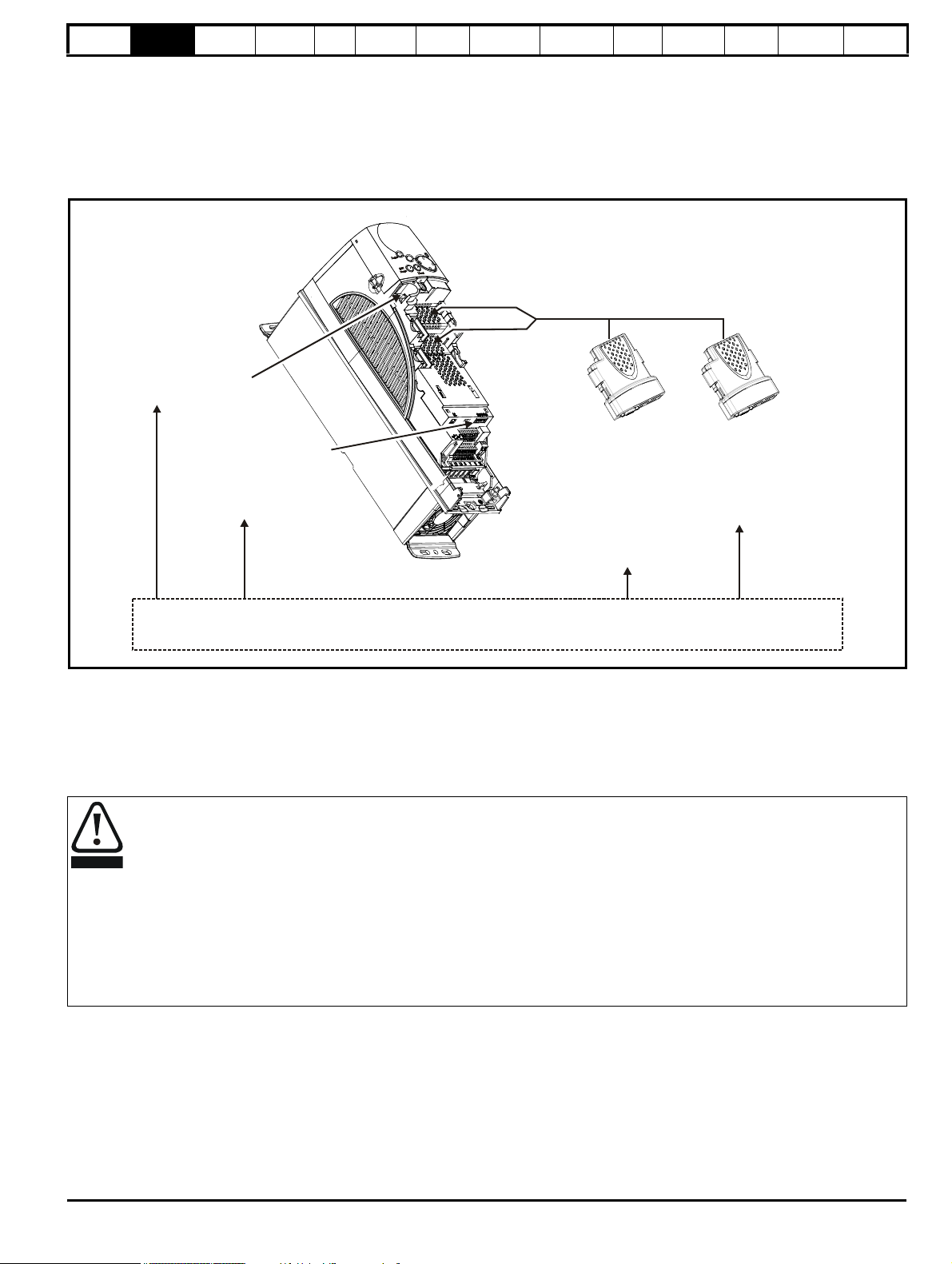
2.1 Introduction
The Affinity is a high performance open loop AC drive specifically designed for use in building automation HVAC/R applications. Figure 2-1 below
indicates the key product features including built in connectivity to building automation systems. Each drive is equipped with two identical option slots
for I/O and communications expansion
Figure 2-1 Features
The Affinity drive can be used as a standalone motor controller or integrated into a building automation system using analog and digital I/O or serial
communications. The base drive incorporates a RS-485 serial communications port that is selectable between BACnet, Metasys N2 or Modbus RTU.
LonWorks, Ethernet, Profibus and Devicenet connectivity is achieved with the addition of plug-in Solutions Modules.
Key features:
Fire Mode
Fire Mode is a configurable override function that is used to alter the operation of the drive based upon external inputs, typically a discrete digital
input from a Building Management Fire Protection system (refer to section 11.21.3 Fire mode on page 216).
Real time Clock
An internal real time clock is available which is used for the timer functions and trip log
Timer functions
Two timers are available to switch an output on a routine basis
Sleep/Wake Mode
Sleep/wake mode stops and starts the motor during periods of low demand to improve system efficiency
Advanced Process PID
Two PIDs are available which can operate independently or combine to provide more complex functionality
Fire Mode - Important Warning
When Fire Mode is active the motor overload and thermal protection are disabled, as well as a number of drive protection functions. Fire
Mode is provided for use only in emergency situations where the safety risk from disabling protection is less than the risk from the drive
tripping - typically in smoke extraction operation to permit evacuation of a building. The use of Fire Mode itself causes a risk of fire from
overloading of the motor or drive, so it must only be used after careful consideration of the balance of risks.
Care must be taken to prevent inadvertent activation or de-activation of Fire Mode. Fire Mode is indicated by a flashing display text
warning "Fire mode active".
Care must be taken to ensure that parameters Pr 1.53 or Pr 1.54 are not inadvertently re-allocated to different inputs or variables. It should
be noted that, by default, Pr 1.54 is controlled from digital input 4 and changing Pr 6.04 or Pr 8.24 can re-allocate this digital input to another
parameter. These parameters are at access level 2 in order to minimize the risk of inadvertent or unauthorized changes. It is recommended
that User Security be applied to further reduce the risk (see section 5.10 Parameter access level and security on page 97). These
parameters may also be changed via serial communications so adequate precautions should be taken if this functionality is utilized.
Affinity User Guide 9
Issue Number: 5 www.controltechniques.com
Page 10
Safety
NOTE
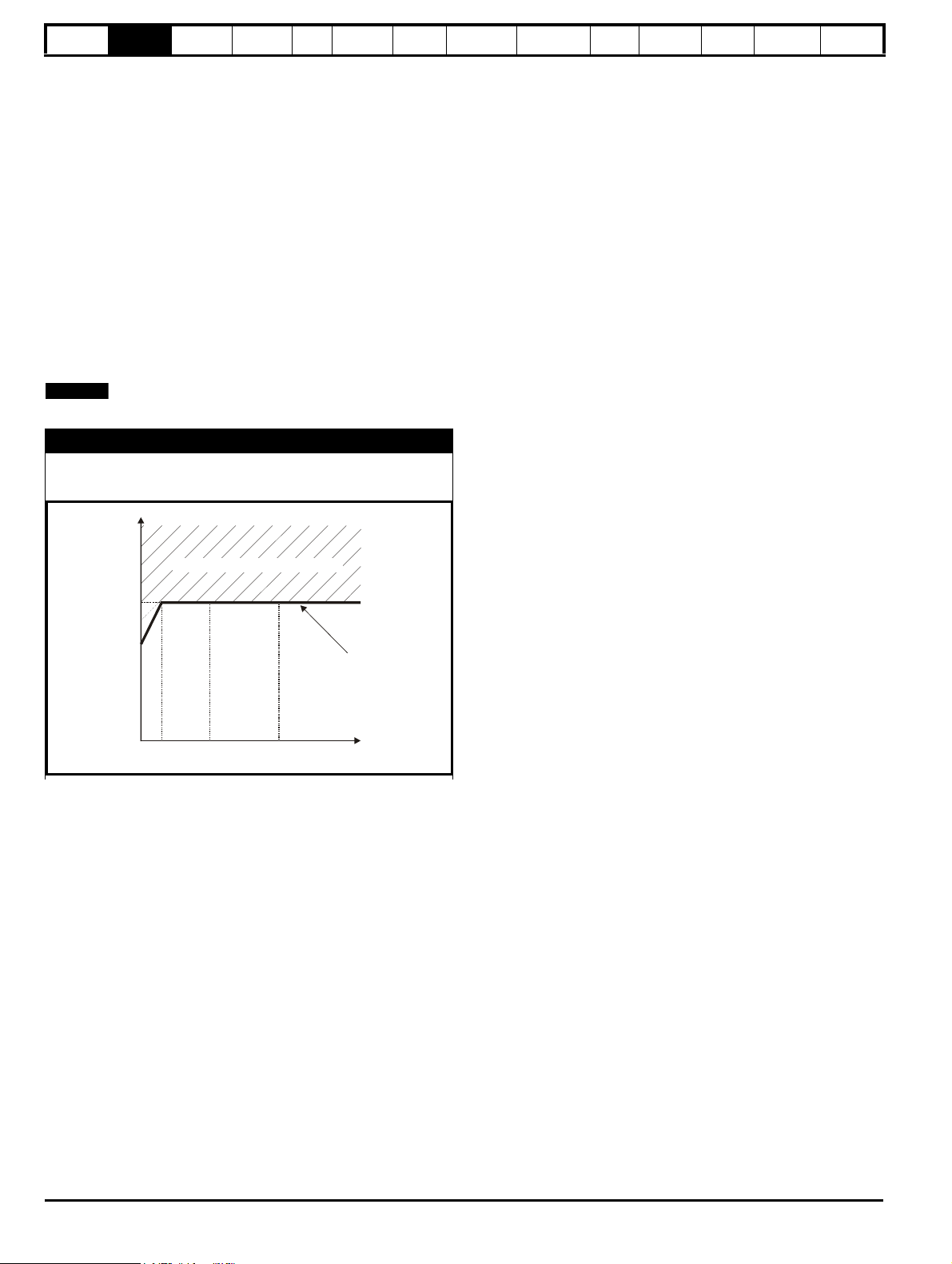
Motor total
current (Pr 4.01)
as a percentage
of motor rated
current
Motor speed as a
percentage of base speed
100%
Max. permissible
continuous
current
100%
I t protection operates in this region
2
70%
50%15%
Information
Product
Information
Mechanical
Installation
Electrical
Installation
Getting
Star ted
Basic
parameters
Running
the motor
Optimization
SMARTCARD
operation
PC tools
Advanced
parameters
Technical
Data
Diagnostics
UL Listing
Information
2.2 Drive types
There are three versions of Affinity drive available:
• Standard
• IP54 (NEMA12)
• IP66 (NEMA12)
The IP54 and IP66 drives are identified by additional characters at the end of the model number, i.e. E12/E54 or E12/E66. The standard drive has no
additional characters.
The standard drives are rated to IP20/NEMA1. Drive sizes 1 and 3 conform to UL Type 1 and sizes 4 to 6 are Open Class. If the optional conduit box
(refer to section 3.5 Mounting methods on page 31) is installed, then drive sizes 4 to 6 conform to UL Type 1.
The E12/E54 and E12/E66 drives have an additional cover installed. They are rated to IP54/NEMA12 and IP66/NEMA12 respectively and both
conform to UL Type 12. E12/E54 and E12/E66 drive sizes 1 to 3 have an internal fan installed to re-circulate the air. The larger drive sizes have fans
installed to the cover to provide forced ventilation using filtered air.
2.3 Ratings
Self ventilated (TENV/TEFC) induction motors require increased protection against overload due to the reduced cooling effect of the fan at low speed.
To provide the correct level of protection the I
The protection starts when the motor speed is below 50% of base speed.
Operation of motor I2t protection (It.AC trip)
2
Motor I
t protection is fixed as shown below and is compatible with:
• Self ventilated (TENV/TEFC) induction motors
2
t software operates at a level which is speed dependent. This is illustrated in the graph below.
10 Affinity User Guide
www.controltechniques.com Issue Number: 5
Page 11

Safety
1
2
3
4
55
Information
Product
Information
Mechanical
Installation
Electrical
Installation
Getting
Star ted
Basic
parameters
Running
the motor
Optimization
SMARTCARD
operation
PC tools
Advanced
parameters
Technical
Data
Diagnostics
UL Listing
Information
For size 1 to 6 standard drives, size 1 to 3 E12/54 drives and size 1 to 3 E12/E66 drives, the continuous current ratings given are for maximum 40°C
(104°F),1000m altitude and 3.0kHz switching. For size 4 to 6 E12/54 drives, the continuous current ratings given are for maximum 35°C
(95°F),1000m altitude and 3.0kHz switching. For further information refer to section 12.1.1 Power and current ratings (Derating for switching
frequency and temperature) on page 228.
Table 2-1 200V Drive ratings (200V to 240V ±10%)
Model
Maximum continuous
output current
AkWhpA
1201 5.2 1.1 1.5 5.7
1202 6.8 1.5 2.0 7.4
1203 9.6 2.2 3.0 10.5
1204 11 3.0 3.0 12.1
2201 15.5 4.0 5.0 17.0
2202 22 5.5 7.5 24.2
2203 28 7.5 10 30.8
3201 42 11 15 46
3202 54 15 20 59
4201 68 18.5 25 74
4202 80 22 30 88
4203 104 30 40 114
Nominal power
at 220V
Motor power
at 230V
Peak current
5201 130 37 50 143
5202 154 45 60 169
Affinity User Guide 11
Issue Number: 5 www.controltechniques.com
Page 12
Safety
1
2
3
4
55
56
Information
Product
Information
Mechanical
Installation
Electrical
Installation
Getting
Star ted
Basic
parameters
Running
the motor
Optimization
SMARTCARD
operation
PC tools
Advanced
parameters
Technical
Data
Diagnostics
UL Listing
Information
For size 1 to 6 standard drives, size 1 to 3 E12/54 drives, and size 1 to 3 E12/E66 drives, the continuous current ratings given are for maximum 40°C
(104°F),1000m altitude and 3.0kHz switching. For size 4 to 6 E12/54 drives, the continuous current ratings given are for maximum 35°C
(95°F),1000m altitude and 3.0kHz switching. For further information refer to section 12.1.1 Power and current ratings (Derating for switching
frequency and temperature) on page 228.
Table 2-2 400V Drive ratings (380V to 480V ±10%)
Maximum continuous
Model
1401 2.8 1.1 1.5 3.0
1402 3.8 1.5 2.0 4.1
1403 5.0 2.2 3.0 5.5
1404 6.9 3.0 5.0 7.5
1405 8.8 4.0 5.0 9.6
1406 11 5.5 7.5 12.1
2401 15.3 7.5 10 16.8
2402 21 11 15 23
2403 29 15 20 31
3401 35 18.5 25 38
3402 43 22 30 47
3403 56 30 40 61
4401 68 37 50 74
4402 83 45 60 91
output current
AkWhpA
Nominal power
at 400V
Motor power
at 460V
Peak current
4403 104 55 75 114
5401 138 75 100 151
5402 168 90 125 184
6401 205 110 150 225
6402 236 132 200 259
12 Affinity User Guide
www.controltechniques.com Issue Number: 5
Page 13
Safety
3
4
55
56
4
55
56
Information
Product
Information
Mechanical
Installation
Electrical
Installation
Getting
Star ted
Basic
parameters
Running
the motor
Optimization
SMARTCARD
operation
PC tools
Advanced
parameters
Technical
Data
Diagnostics
UL Listing
Information
For size 1 to 6 standard drives, size 1 to 3 E12/54 drives, and size 1 to 3 E12/E66 drives, the continuous current ratings given are for maximum 40°C
(104°F),1000m altitude and 3.0kHz switching. For size 4 to 6 E12/54 drives, the continuous current ratings given are for maximum 35°C
(95°F),1000m altitude and 3.0kHz switching. For further information refer to section 12.1.1 Power and current ratings (Derating for switching
frequency and temperature) on page 228.
Table 2-3 575V Drive ratings (500V to 575V ±10%)
Model
Maximum continuous
output current
AkWhpA
3501 5.4 3.0 3.0 5.9
3502 6.1 4.0 5.0 6.7
3503 8.4 5.5 7.5 9.2
3504 11 7.5 10 12.1
3505 16 11 15 17.6
3506 22 15 20 24.2
3507 27 18.5 25 29.7
4603 36 22 30 39.6
4604 43 30 40 47.3
4605 52 37 50 57.2
4606 62 45 60 68
5601 84 55 75 92
5602 99 75 100 108
Nominal power
at 575V
Motor power
at 575V
Peak current
6601 125 90 125 137
6602 144 110 150 158
The power ratings above for model size 4 and larger are for the 690V drives when used on a 500V to 575V supply.
Table 2-4 690V Drive ratings (500V to 690V ±10%)
Model
Maximum continuous
output current
AkWhpA
4601 22 18.5 25 24.2
4602 27 22 30 29.7
4603 36 30 40 39.6
4604 43 37 50 47.3
4605 52 45 60 57.2
4606 62 55 75 68.2
5601 84 75 100 92
5602 99 90 125 108
Nominal power
at 690V
Motor power
at 690V
Peak current
6601 125 110 150 137
6602 144 132 175 158
Affinity User Guide 13
Issue Number: 5 www.controltechniques.com
Page 14

Safety
NOTE
Product line
BA: Affinity Building
product
Automation
Frame size
Vol ta ge r at ing
0:
2:
4:
5:
6:
Voltage independent
200V to 240V
380V to 480V
500V to 575V
500V to 690V
Current rating step
BA 6 4 0 1 -E12/E54
Variant designator
None:
E12/E54:
Standard drive
UL Type 12 (NEMA 12) / IP54
UL Type 12 (NEMA 12) / IP66
E12/E66:
Information
Product
Information
Mechanical
Installation
Electrical
Installation
Getting
Star ted
Basic
parameters
Running
the motor
Optimization
SMARTCARD
operation
PC tools
Advanced
parameters
Technical
Data
Diagnostics
UL Listing
Information
2.3.1 Typical short term overload limits
The maximum percentage overload limit changes depending on the selected motor. Variations in motor rated current, motor power factor and motor
leakage inductance all result in changes in the maximum possible overload. The exact value for a specific motor can be calculated using the
equations detailed in Menu 4 in the Advanced User Guide.
Typical values are shown in the table below for RFC mode (RFC) and open loop (OL) modes:
Table 2-5 Typical overload limits for size 1 to 6
Operating mode RFC mode from cold RFC mode from 100% Open loop from cold Open loop from 100%
Overload with motor rated current = drive rated current 110% for 165s 110% for 9s 110% for 165s 110% for 9s
Generally the drive rated current is higher than the matching motor rated current allowing a higher level of overload than the default setting as
illustrated by the example of a typical 4 pole motor.
The time allowed in the overload region is proportionally reduced at very low output frequency.
The maximum overload level which can be attained is independent of the speed.
2.4 Model number
The way in which the model numbers for the Affinity range are formed is
illustrated below.
Quadratic V/F mode
The voltage applied to the motor is directly proportional to the square of
the frequency except at low speed where a voltage boost is provided
which is set by the user. This mode can be used for running fan or pump
applications with quadratic load characteristics or for multi-motor
applications. This mode is not suitable for applications requiring a high
starting torque.
2.5.2 RFC mode
Rotor flux control provides closed loop control without the need for
position feedback by using current, voltages and key motor parameters
to estimate the motor speed. It can eliminate instability traditionally
associated with open loop control such as operating large motors with
light loads at low frequencies.
For further details, refer to section 8.1.2 RFC mode on page 124.
2.5 Operating modes
The Affinity is designed to operate in any of the following modes:
1. Open loop mode
Open loop vector mode
Fixed V/F mode (V/Hz)
Quadratic V/F mode (V/Hz)
2. RFC mode
2.5.1 Open loop mode
The drive applies power to the motor at frequencies varied by the user.
The motor speed is a result of the output frequency of the drive and slip
due to the mechanical load. The drive can improve the speed control of
the motor by applying slip compensation. The performance at low speed
depends on whether V/F mode or open loop vector mode is selected.
For further details refer to section 8.1.1 Open loop motor control on
page 121.
Open loop vector mode
The voltage applied to the motor is directly proportional to the frequency
except at low speed where the drive uses motor parameters to apply the
correct voltage to keep the flux constant under varying load conditions.
Typically 100% torque is available down to 1Hz for a 50Hz motor.
Fixed V/F mode
The voltage applied to the motor is directly proportional to the frequency
except at low speed where a voltage boost is provided which is set by
the user. This mode can be used for multi-motor applications.
Typically 100% torque is available down to 4Hz for a 50Hz motor.
14 Affinity User Guide
www.controltechniques.com Issue Number: 5
Page 15

Safety
2
Solutions Module
slot 2
SMARTCARD
slot
Keypad
connection
PC
communications
port (RS485)
Solutions Module
slot 1
Rating label
Status LED
Approvals label
Relay terminals
AC supply /
motor
connections
AC supply /
motor
connections
Internal
EMC
filter
Internal
EMC
filter
AC supply /
motor
connections
Internal
EMC
filter
4
Motor
connections
AC
supply
Internal
EMC filter
DC
supply
Brake
resistor
5
AC
supply
Internal
EMC filter
DC
supply
Motor
connections
Brake
resistor6AC
supply
Internal
EMC filter
DC
supply
Motor
connections
Heatsink fan
supply connections
Brake
resistor
3
Power
stage
label
Power
stage
label
1
Control
terminals
Building automation
network connector
Building automation
interface
±
DC bus /
Braking
±
DC bus (High
current) / Braking
±
DC bus
(Low current)
±
DC bus (High
current) / Braking
±
DC bus
(Low current)
NOTE
Information
Product
Information
2.6 Drive features
Figure 2-2 Features of the drive
Mechanical
Installation
Electrical
Installation
Getting
Star ted
Basic
parameters
Running
the motor
Optimization
SMARTCARD
operation
PC tools
Advanced
parameters
Technical
Data
Diagnostics
UL Listing
Information
The size 6 drive requires a 24V supply for the heatsink fan.
Affinity User Guide 15
Issue Number: 5 www.controltechniques.com
Page 16

Safety
I/P 200-240V 50-60Hz 3ph 7.1A
O/P 0-240V 5.2A
Model
Input voltage
rating
Input
frequency
No. of
phases
Typical input
current for
Normal Duty
rating
Output
current
Output voltage
range
Standard rating label (size 1 to 6)
S.No:
3000005001
Serial
number
Model
Customer and
date code
Approvals
IND.
CONT.
EQ.
Please read manual before connecting.
BA1201
STDL25
Stored charge 10 min
Type 1-Plenum rated
Ser No:
3000005001
Made In U.K
Serial
number
Standard approvals label (Size 1 to 6)
Model
Customer and
date code
Approvals
Please read manual before connecting.
BA5402
STDN39
Stored charge 10 min
Ser No: 3000005001
Made In U.K
Serial
number
Standard power stage label (Size 5 and 6 only)
I/P 380-480V 50-60Hz 3ph 152.0A
O/P 0-480V
168A
Input voltage
Output voltage
Input
frequency
No. of phases &
Typical input current for
Normal Duty rating
Output
current
1.1 kW
Only applies
to sizes 1 to 3
IND.
CONT.
EQ.
E12/E54 rating label
LISTED8D14
E171230
R
Model
Customer and
date code
Approvals
Please read manual before connecting.
STDN39
Ser No: 3000005001
Made In U.K
E171230
IND.
CONT.
EQ.
Stored charge 10 min
R
N1652
Serial number
N1652
LISTED8D14
E171230
R
N1652
E12/E66 rating label
BA1204-E12/E66 S.No: 3000005001
I/P 200-240V 50-60Hz 3ph 15.4A
O/P 0-240V 11.0A
Please read manual before connecting.
BA1204-E12 / E66 3.0kW
Stored charge 10 min
Made In U.K
E171230
IND.
CONT.
EQ.
R
N1652
STDN39
Ser No: 3000005001
Model
Serial number
Approvals
CE approval Europe
C Tick approval Australia
UL / cUL approval
USA &
Canada
R
Key to approvals
Information
Product
Information
Mechanical
Installation
Electrical
Installation
Getting
Star ted
2.7 Nameplate description
See Figure 2-2 for location of rating labels.
Figure 2-3 Typical drive rating labels
Basic
parameters
Running
the motor
Optimization
SMARTCARD
operation
PC tools
Advanced
parameters
Technical
Data
Diagnostics
UL Listing
Information
16 Affinity User Guide
www.controltechniques.com Issue Number: 5
Page 17

Safety
Fieldbus
Automation:
(I/O Expansion)
(Applications)
CT Comms
cable
External
footprint /
bookcase
EMC filter
Conduit box*
• Digital inputs x 3
• Analog output (voltage) x 1
• Digital I/O x 3 • Relay x 2
• Analog inputs (voltage) x 2
Information
Product
Information
Mechanical
Installation
Electrical
Installation
2.8 Options
Figure 2-4 Options available with Affinity
Getting
Star ted
Basic
parameters
Running
the motor
Optimization
SMARTCARD
operation
PC tools
Advanced
parameters
Technical
Data
Diagnostics
UL Listing
Information
* For sizes 1 and 2 there is only a bottom conduit box available. For sizes 3 to 6 there is a top and bottom conduit box available.
All Solutions Modules are color-coded in order to make identification easy. The following table shows the color-code key and gives further details on
their function.
Table 2-6 Solutions Module identification
Type Solutions Module Color Name Further Details
Extended I/O interface
Increases the I/O capability by adding the following to the
Yellow SM-I/O Plus
existing I/O in the drive:
Extended I/O interface
Increase the I/O capability by adding the following to the
Yellow SM-I/O 32
existing I/O in the drive:
• High speed digital I/O x 32
• +24V output
Additional I/O
Automation
(I/O
Expansion)
Dark Yellow SM-I/O Lite
1 x Analog input (± 10V bi-polar or current modes)
1 x Analog output (0-10V or current modes)
3 x Digital input and 1 x Relay
Isolated I/O to NAMUR NE37 specifications
For chemical industry applications
Turquoise SM-I/O PELV
1 x Analog input (current modes)
2 x Analog outputs (current modes)
4 x Digital input / outputs, 1 x Digital input, 2 x Relay outputs
Olive SM-I/O 120V
Additional I/O conforming to IEC 61131-2 120Vac
6 digital inputs and 2 relay outputs rated for 120Vac operation
Affinity User Guide 17
Issue Number: 5 www.controltechniques.com
Cobalt Blue SM-I/O 24V Protected
Additional I/O with overvoltage protection up to 48V
2 x Analog outputs (current modes)
4 x Digital input / outputs, 3 x Digital inputs, 2 x Relay outputs
Page 18

Safety
Information
Product
Information
Mechanical
Installation
Electrical
Installation
Getting
Star ted
Basic
parameters
Running
the motor
Optimization
SMARTCARD
operation
PC tools
Advanced
parameters
Table 2-6 Solutions Module identification
Type Solutions Module Color Name Further Details
Applications Processor (with CTNet)
Dark Green SM-Applications
nd
2
processor for running pre-defined and /or customer created
application software with CTNet support
Applications Processor
White SM-Applications Lite
Automation
(Applications)
Moss Green SM-Applications Plus
nd
2
processor for running pre-defined and /or customer created
application software
Applications Processor (with CTNet)
nd
processor for running pre-defined and /or customer created
2
application software with CTNet support. Enhanced
performance over SM-Applications
Applications Processor
nd
2
White SM-Applications Lite V2
processor for running pre-defined and /or customer created
application software. Enhanced performance over SMApplications Lite
Technical
Data
Diagnostics
UL Listing
Information
Fieldbus
Brown Red SM-EtherCAT
Purple SM-PROFIBUS-DP-V1
Medium Grey SM-DeviceNet
Beige SM-Ethernet
Pale Green SM-LON
Dark Grey SM-INTERBUS
Pink SM-CAN
Light Grey SM-CANopen
EtherCAT option
EtherCAT adapter for communications with the drive
Profibus option
PROFIBUS DP adapter for communications with the drive
DeviceNet option
Devicenet adapter for communications with the drive
Ethernet option
10 base-T / 100 base-T; Supports web pages, SMTP mail and
multiple protocols: DHCP IP addressing; Standard RJ45
connection
LonWorks option
LonWorks adapter for communications with the drive
Interbus option
Interbus adapter for communications with the drive
CAN option
CAN adapter for communications with the drive
CANopen option
CANopen adapter for communications with the drive
SERCOS option
Class B compliant. Torque velocity and position control modes
Red SM-SERCOS
supported with data rates (bit/s): 2MB, 4MB, 8MB and 16MB.
Minimum 250μs network cycle time. Two digital high speed
probe inputs 1μs for position capture
18 Affinity User Guide
www.controltechniques.com Issue Number: 5
Page 19

Safety
M6
M6
M6
M6
M8
M8x20
Information
Product
Information
Mechanical
Installation
Electrical
Installation
Getting
Star ted
Basic
parameters
Running
the motor
Optimization
SMARTCARD
operation
PC tools
Advanced
parameters
Technical
Data
Diagnostics
UL Listing
Information
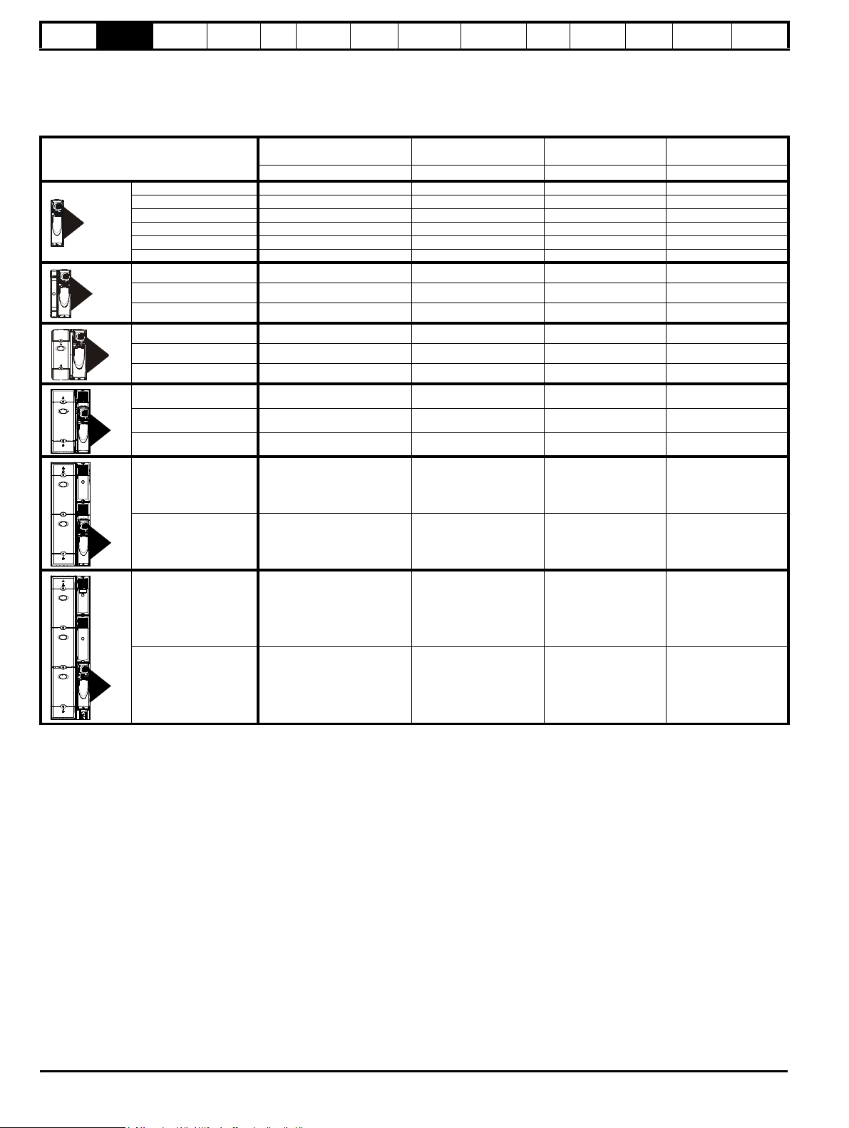
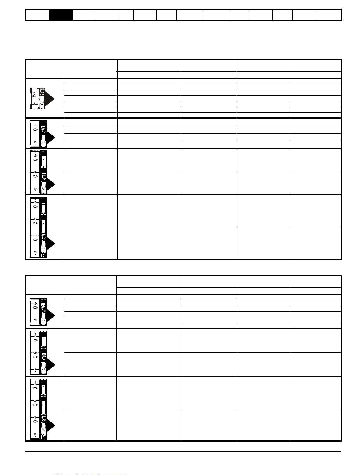
2.9 Items supplied with the drive
The drive is supplied with a BA-Keypad, a printed manual, a SMARTCARD, a safety information booklet, the Certificate of Quality, an accessory kit
box including the items shown in Table 2-7, and a CD ROM containing all related product documentation and software tools.
Table 2-7 Parts supplied with the drive
Description Size 1 Size 2 Size 3 Size 4 Size 5 Size 6
Control
connectors
Relay connector
Grounding
bracket
Through panel
mounting gasket*
HVAC/R
communication
connector
Through panel
mounting bracket
Surface
mounting
brackets
E12/E54 surface
mounting brackets
Top surface
mounting
brackets*
Nylon washers*
Sealing clips*
Mounting screws
Grounding clamp
Ground cable
bridge
DC terminal
cover grommets*
Ferrite ring
Supply and
motor connector
Fan supply
connector
IP54 gasket*
IP54 insert*
BA-Keypad
Affinity User Guide 19
Issue Number: 5 www.controltechniques.com
Page 20

Safety
WARNING
WARNING
WARNING
Information
Product
Information
Mechanical
Installation
Electrical
Installation
Getting
Star ted
Basic
parameters
Running
the motor
Optimization
SMARTCARD
operation
PC tools
Advanced
parameters
Technical
Data
Diagnostics
UL Listing
Information
3 Mechanical installation
This chapter describes how to use all mechanical details to install the
drive.
The standard drive is rated as IP20/UL Type 1 for size 1 to 3 and IP20/
open class for size 4 to 6. If the optional conduit box is installed, then
size 4 to 6 are rated as UL Type 1. (The conduit box is an additional
accessory for all sizes of the standard drive and is required for conduit
connection to the drive).
The standard drive is intended to be installed as appropriate for the
country where the equipment is used e.g. inside an additional enclosure,
plenum or on a plant room wall.
The E12/E54 and E12/E66 drives have additional covers installed.
The E12/E54 drive is IP54/UL Type 12 rated and as such may be
installed on a plant room wall and requires no additional enclosure.
The E12/E66 drive is IP66/UL Type 12 rated and as such may be
installed in areas subject to wash-down, and requires no additional
enclosure.
The E12/E66 drives can also be installed externally subject to the notes
given in section 3.2.3.
The UL Type 1 and UL Type 12 drives are also plenum rated and are
therefore suitable for Plenum mounting applications.
Key features of this chapter include:
• Planning the installation
• Terminal cover removal
• Conduit and conduit connection
• Solutions Module installation
• Surface mounting standard drive
• Through-hole mounting standard drive
• E12/E54 mounting
• Through panel mounting standard drive in an IP54/UL Type 12
enclosure
• Enclosure sizing and layout
• Terminal location and torque settings
3.1 Safety information
Follow the instructions
The mechanical and electrical installation instructions must
be adhered to. Any questions or doubt should be referred to
the supplier of the equipment. It is the responsibility of the
owner or user to ensure that the installation of the drive and
any external option unit, and the way in which they are
operated and maintained, comply with the requirements of
the Health and Safety at Work Act in the United Kingdom or
applicable legislation and regulations and codes of practice in
the country in which the equipment is used.
Competence of the installer
The drive must be installed by professional assemblers who
are familiar with the requirements for safety and EMC. The
assembler is responsible for ensuring that the end product or
system complies with all the relevant laws in the country
where it is to be used.
Many of the drives in this product range weigh in excess of
15kg (33lb). Use appropriate safeguards when lifting these
models.
A full list of drive weights can be found in section
12.1.18 Weights on page 241
3.2 Planning the installation
The following considerations must be made when planning the installation:
3.2.1 Access
Access must be restricted to authorized personnel only. Safety
regulations which apply at the place of use must be complied with.
3.2.2 Environmental protection
The standard drive must be protected from:
• moisture, including dripping water or spraying water and
condensation. An anti-condensation heater may be required, which
must be switched off when the drive is running.
• contamination with electrically conductive material
• contamination with any form of dust which may restrict the fan, or
impair airflow over various components
• temperature beyond the specified operating and storage ranges
• corrosive gasses
The E12/E54 variant is protected from airborne dust, splashing water
and non-corrosive liquids. The E12/E66 variant is dust-tight and
protected from powerful jets of water, heavy seas and non-corrosive
liquids.
3.2.3 External installations
The E12/E54 and E12/E66 drives may be installed externally, but it
should be noted that the drive covers could degrade over a long period
of time if they are subjected to high levels of UV radiation. It is therefore
advisable to provide some degree of shade, or preferably to mount the
drive where it receives little or no direct sunlight.
3.2.4 Cooling
If mounting the drive in an enclosure the heat produced must be
removed without its specified operating temperature being exceeded.
Note that a sealed enclosure gives much reduced cooling compared with
a ventilated one, and may need to be larger and/or use internal air
circulating fans.
For further information, refer to section 3.6.2 Enclosure sizing on
page 48.
The E12/E54 drive has an additional fan installed internally to assist
cooling by circulating air between the outer cover and the drive or
filtering air through external vents (size 4 to 6).
3.2.5 Electrical safety
The installation must be safe under normal and fault conditions.
Electrical installation instructions are given in Chapter 4 Electrical
installation on page 66.
3.2.6 Fire protection
The drive enclosure is not classified as a fire enclosure. A separate fire
enclosure must be provided.
For installation in the USA, a NEMA 12 enclosure is suitable.
For installation outside the USA, the following (based on IEC 62109-1,
standard for PV inverters) is recommended.
• Enclosure can be metal and/or polymeric, polymer must meet
requirements which can be summarised for larger enclosures as
using materials meeting at least UL 94 class 5VB at the point of
minimum thickness.
• Air filter assemblies to be at least class V-2.
• The location and size of the bottom shall cover the area shown in
Figure 3-1. Any part of the side which is within the area traced out by
the 5° angle is also considered to be part of the bottom of the fire
enclosure.
20 Affinity User Guide
www.controltechniques.com Issue Number: 5
Page 21

Safety
Drive
5
o
5
o
Notless
tha n 2 X
Baffle plates(m ay be
above orbelow bottom
ofenclosure)
X
Bo ttom of fire
enclosure
Not less
than 2
times ‘X’
Baffle plates (may be above or
below bottom of enclosure)
Bottom of fire enclosure
X
Information
Product
Information
Mechanical
Installation
Electrical
Installation
Getting
Star ted
Basic
parameters
Running
the motor
Figure 3-1 Fire enclosure bottom layout
The bottom, including the part of the side considered to be part of the
bottom, must be designed to prevent escape of burning material - either
by having no openings or by having a baffle construction. This means
that openings for cables etc. must be sealed with materials meeting the
5VB requirement, or else have a baffle above. See Figure 3-2 for
acceptable baffle construction. This does not apply for mounting in an
enclosed electrical operating area (restricted access) with concrete floor.
Figure 3-2 Fire enclosure baffle construction
Optimization
SMARTCARD
operation
PC tools
Advanced
parameters
Technical
Data
Diagnostics
UL Listing
Information
3.2.7 Electromagnetic compatibility
Variable speed drives are powerful electronic circuits which can cause
electromagnetic interference if not installed correctly with careful
attention to the layout of the wiring.
Some simple routine precautions can prevent disturbance to typical
industrial control equipment.
If it is necessary to meet strict emission limits, or if it is known that
electromagnetically sensitive equipment is located nearby, then full
precautions must be observed. In-built into the drive, is an internal EMC
filter, which reduces emissions under certain conditions. If these
conditions are exceeded, then the use of an external EMC filter may be
required at the drive inputs, which must be located very close to the
drives. Space must be made available for the filters and allowance made
for carefully segregated wiring. Both levels of precautions are covered in
section 4.11 EMC (Electromagnetic compatibility) on page 78.
3.2.8 Hazardous areas
The drive must not be located in a classified hazardous area unless it is
installed in an approved enclosure and the installation is certified.
Affinity User Guide 21
Issue Number: 5 www.controltechniques.com
Page 22

Safety
WARNING
WARNING
Information
Product
Information
Mechanical
Installation
Electrical
Installation
Getting
Star ted
Basic
parameters
Running
the motor
3.3 Terminal cover removal
Isolation device
The AC supply must be disconnected from the drive using an
approved isolation device before any cover is removed from
the drive or before any servicing work is performed.
Stored charge
The drive contains capacitors that remain charged to a
potentially lethal voltage after the AC supply has been
disconnected. If the drive has been energized, the AC
supply must be isolated at least ten minutes before work
may continue.
Normally, the capacitors are discharged by an internal
resistor. Under certain, unusual fault conditions, it is possible
that the capacitors may fail to discharge, or be prevented
from being discharged by a voltage applied to the output
terminals. If the drive has failed in a manner that causes the
display to go blank immediately, it is possible the capacitors
will not be discharged. In this case, consult Control
Techniques or their authorized distributor.
3.3.1 Removing the terminal covers
Standard drive
Size 1 is installed with two terminal covers: AC/Control and DC terminal
covers.
Size 2 is installed with three terminal covers: AC/Control , High current
DC / Braking and low voltage DC terminal covers.
Size 3 is installed with four terminal covers: Control, High current DC /
Braking, low voltage DC and AC terminal covers.
Size 4, 5 and 6 are installed with three terminal covers: Control, input
and output terminal covers.
In order to provide access to the mounting holes when a size 1, 2 or 3
drive is through-panel mounted, the control terminal cover must be
removed. For size 3 the high current DC / Braking and AC terminal
covers must also be removed. Once the drive has been mounted, the
terminal covers can be replaced.
E12/E54 and E12/E66
Size 1 to 4 are only installed with 1 outer cover which is held on by 6
sealing screws. By removing this cover access can be gained to all
power and control terminals as per the standard drive. No further covers
require removal.
Size 5 and 6 are installed with 2 removable covers, top and bottom, for
access to input, output and control terminals.
Optimization
SMARTCARD
operation
PC tools
Advanced
parameters
Technical
Data
Diagnostics
UL Listing
Information
22 Affinity User Guide
www.controltechniques.com Issue Number: 5
Page 23

Safety
DC
AC/Control
Low
voltage DC
AC/Control ControlAC
Braking
Input
ControlOutput ControlOutput
Control
Output
Input
Input
21 3
4 5
6
Low
voltage DC
Braking
Information
Product
Information
Mechanical
Installation
Electrical
Installation
Getting
Star ted
Basic
parameters
Running
the motor
Optimization
Figure 3-3 Location and identification of standard drive terminal covers
SMARTCARD
operation
PC tools
Advanced
parameters
Technical
Data
Diagnostics
UL Listing
Information
Affinity User Guide 23
Issue Number: 5 www.controltechniques.com
Page 24

Safety
Pozi Pz2
Pozi Pz2
Pozi Pz2
Information
Product
Information
Mechanical
Installation
Electrical
Installation
Getting
Star ted
Basic
parameters
Running
the motor
Optimization
SMARTCARD
operation
PC tools
Advanced
parameters
Technical
Data
Diagnostics
UL Listing
Information
To remove a terminal cover, undo the screw and lift the terminal cover off as shown. The control terminal cover must be removed first before the DC
(size 1) / low voltage DC (sizes 2 and 3) terminal cover can be removed.
When replacing the terminal covers the screws should be tightened with a maximum torque of 1 N m (0.7 lb ft).
Figure 3-4 Removing the standard drive size 1 terminal covers
Figure 3-5 Removing the standard drive size 2 terminal covers
Figure 3-6 Removing the standard drive size 3 terminal covers
24 Affinity User Guide
www.controltechniques.com Issue Number: 5
Page 25
Safety
Pozi Pz2
1
2
All sizes
Size 3
only
1
2
1 2
Sizes 4 to 6
only
1
2
1
2
Size 2
only
Sizes
1 to 3
only
NOTE
Information
Product
Information
Mechanical
Installation
Electrical
Installation
Getting
Star ted
Basic
parameters
Running
the motor
Optimization
SMARTCARD
operation
Figure 3-7 Removing the size 4, 5 and 6 standard drive terminal covers (size 4 illustrated)
PC tools
Advanced
parameters
Technical
Data
Diagnostics
UL Listing
Information
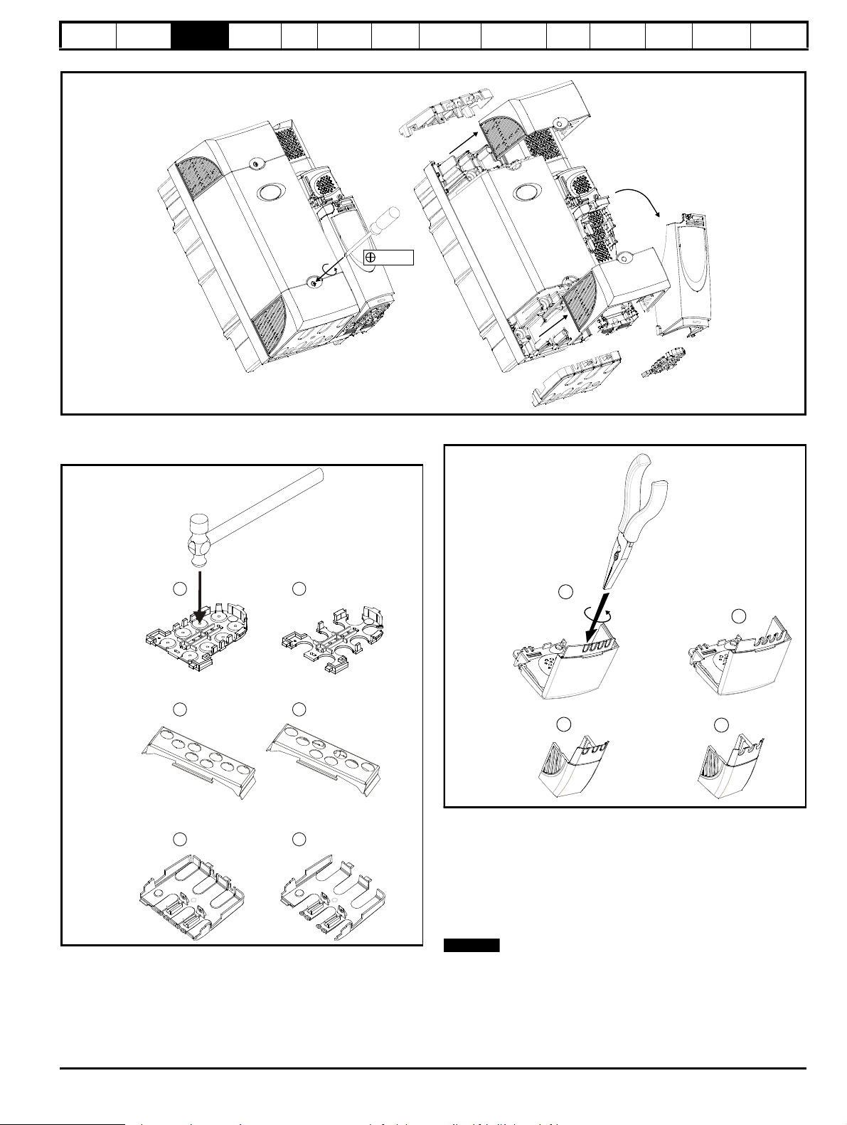
3.3.2 Removing the finger-guard and DC terminal cover break-outs
Figure 3-8 Removing the finger-guard break-outs
Place finger-guard on a flat solid surface and hit relevant break-outs with
hammer as shown (1). Continue until all required break-outs are removed
(2). Remove any flash / sharp edges once the break-outs are removed.
Figure 3-9 Removing the DC terminal cover break-outs
Grasp the DC terminal cover break-outs with pliers as shown (1) and
twist to remove. Continue until all required break-outs are removed (2).
Remove any flash / sharp edges once the break-outs are removed. Use
the DC terminal cover grommets supplied in the accessory box (Table 27 on page 19) to maintain the seal at the top of the drive.
Grommets are available for the size 4 to 6 finger-guards. Two versions
are available allowing for either single or double cable entries. These are
not required if the optional conduit box is installed.
If the optional conduit box is not installed, then these grommets must be
used to ensure that the IP20 rating is maintained.
Affinity User Guide 25
Issue Number: 5 www.controltechniques.com
Page 26

Safety
Single cable entry grommet
Double cable entry grommet
Information
Product
Information
Mechanical
Installation
Electrical
Installation
Getting
Star ted
Basic
parameters
Running
the motor
Figure 3-10 Size 4 to 6 finger-guard grommets
The grommets are available as a kit of four grommets under the
following part numbers:
9500-0074 Kit of four single entry grommets
9500-0075 Kit of four double entry grommets
3.3.3 Conduit connection boxes
Conduit connection boxes are available as an option. Figure 3-11
demonstrates a conduit connection box installed on a size 4 standard drive.
For further information, refer to section 3.5 Mounting methods on
page 31.
Figure 3-11 Size 4 standard drive with conduit connection box
installed
Optimization
SMARTCARD
operation
PC tools
Advanced
parameters
Technical
Data
Diagnostics
UL Listing
Information
Table 3-1 Conduit box part numbers
Frame size Top conduit box Bottom conduit box
1
6500-0008
2 6500-0011
3 6500-0033* 6500-0014
4 6500-0017 6500-0018
5 6500-0023 6500-0024
6 6500-0027 6500-0028
*For DC or brake connections only.
26 Affinity User Guide
www.controltechniques.com Issue Number: 5
Page 27

Safety
1
2
3
NOTE
Information
Product
Information
Mechanical
Installation
Electrical
Installation
Getting
Star ted
Basic
parameters
Running
the motor
Optimization
3.3.4 E12/E54 and E12/E66 cover removal / installation
Figure 3-12 Removal of the top cover (size 1 to 4) E12/E54
SMARTCARD
operation
PC tools
Advanced
parameters
Technical
Data
Diagnostics
UL Listing
Information
1. Undo 6 x M5 screws
2. Remove cover as shown
3. Disconnect the BA Keypad connector from the RJ 45 serial port
4. Reverse the above procedure to replace the cover
E12/E66 drives are only available in sizes 1 to 3
Affinity User Guide 27
Issue Number: 5 www.controltechniques.com
Page 28
Safety
1
2
1
2
CAUTION
NOTE
NOTE
Information
Product
Information
Mechanical
Installation
Electrical
Installation
Getting
Star ted
parameters
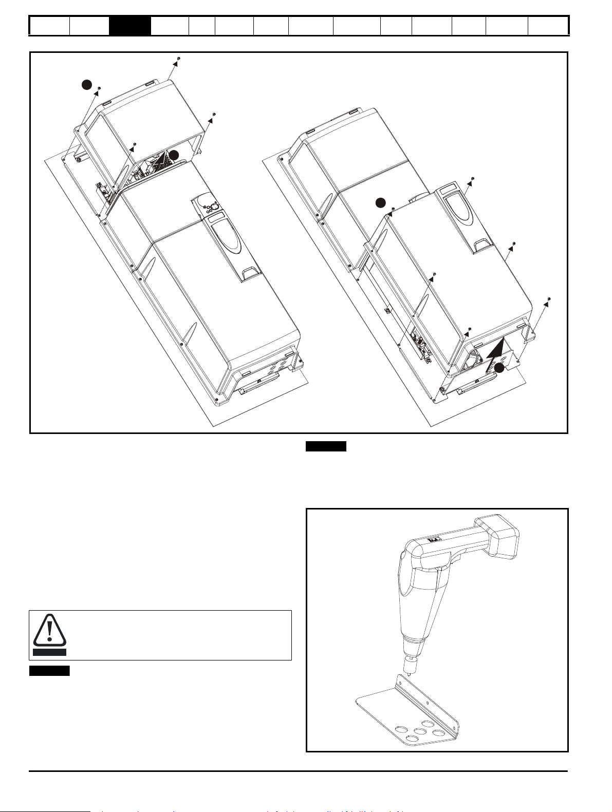
Figure 3-13 Removing the top covers (size 5 to 6)
Basic
Running
the motor
Optimization
SMARTCARD
operation
PC tools
Advanced
parameters
Technical
Data
Diagnostics
UL Listing
Information
1. Undo M5 screws
2. Remove cover as shown
3.3.5 E12/E54 and E12/E66 gland plate drilling
For size 1 and 2 drives, the gland plates have pre-prepared holes
installed with glands for the power, motor and control cables.
For size 3 to 6 E12/E54 and size 3 E12/E66 drives, the pre-prepared
holes in the plate are for control cables only. Custom holes need to be
drilled accordingly for the following reasons:
• To route power and motor cables
• The connection of metal conduit or IP54/IP66 cable conduits
If being used in a Type 12, IP54 or IP66 environment, the correctly rated
glands should be used and installed in accordance with the supplier's
recommendations.
Sizes 4 to 6 have two gland plates, top and bottom.
In order to prevent contamination from metal swarf, the gland
plate should be removed prior to drilling.
These holes are supplied installed with IP55 glands. Care should be
taken when holes are cut in the glands for the cables to pass through,
that the residual gap between the cable and the gland is minimal.
Prior to the removal of the covers, the top conduit plate should be
cleaned / dried to remove any debris or moisture. Care should be taken
to ensure that the cover gaskets are not damaged when removing or
replacing the covers.
Figure 3-14 Drilling the size 3 to 6 E12/E54 gland plate
28 Affinity User Guide
www.controltechniques.com Issue Number: 5
Page 29

Safety
CAUTION
Installing Solutions Module Removing Solutions Module Two Solutions Modules installed
Solutions Module
in slot 1
Solutions Module
in slot 2
A
B
A
NOTE
Removing keypad
A
ABInstalling keypad
WAR NING
NOTE
NOTE
Information
Product
Information
Mechanical
Installation
Electrical
Installation
Getting
Star ted
Basic
parameters
Running
the motor
Optimization
SMARTCARD
3.4 Solutions Module / keypad installation / removal
Power down the drive before installing / removing the
Solutions Module. Failure to do so may result in damage to
the product.
Figure 3-15 Installation and removal of a Solutions Module
operation
PC tools
Advanced
parameters
Technical
Data
Diagnostics
UL Listing
Information
To install the Solutions Module, press down in the direction shown above
until it clicks into place.
To remove the Solutions Module, press inwards at the points shown (A)
and pull in the direction shown (B).
The drive has the facility for both Solutions Module slots to be used at
the same time, as illustrated.
N
It is recommended that Solutions Module slot 2 is used if only one
module is installed.
Figure 3-16 Installation and removal of a keypad
To install, align the keypad and press gently in the direction shown until it
clicks into position.
To remove, while pressing the tabs inwards (A), gently lift the keypad in
the direction indicated (B).
Affinity User Guide 29
Issue Number: 5 www.controltechniques.com
Be aware of live terminals when inserting or removing the
keypad
N
The keypad can be installed / removed while the drive is powered up and
running a motor, providing that the drive is not operating in hand, off or
keypad mode.
The keypad for the E12/E54 drive is installed to the top cover and
connected to the drive via a cable.
Page 30

Safety
NOTE
Information
Product
Information
Mechanical
Installation
Electrical
Installation
Getting
Star ted
Basic
parameters
Running
the motor
The BA keypad cannot be installed on the front of the E12/E66 drive but
can be connected remotely via a serial cable to the external RJ 45
connector (see Figure 3-17 below for location of the RJ 45 connector).
Figure 3-17 location of external RJ 45 connector
The serial cable must be a shielded RJ45 cable with an appropriate
connector (suitable for mating with a Bulgin Buccaneer PX0833), rated
to a minimum of IP66. The maximum cable length is 30 metres.
If a cable is not connected then the connector cap must be installed as
shown in Figure 3-18.
Figure 3-18 RJ 45 connector with cap installed
Optimization
SMARTCARD
operation
PC tools
Advanced
parameters
Technical
Data
Diagnostics
UL Listing
Information
30 Affinity User Guide
www.controltechniques.com Issue Number: 5
Page 31

Safety
WAR NING
WAR NING
100.0mm
(3.937in)
452.0mm
(17.776in)
473.0mm
(18.612in)
219.0mm (8.614in)
40.0
±
±
5.0mm
(1.575 0.196in)
370.0
±
±
1.0mm
(14.567 0.039in)
87.0
±
±
1.0mm
(3.425 0.039in)
66.0
±
±
1.0mm
(2.598 0.039in)
Information
Product
Information
Mechanical
Installation
Electrical
Installation
Getting
Star ted
Basic
parameters
Running
the motor
Optimization
SMARTCARD
operation
PC tools
Advanced
parameters
Technical
Data
Diagnostics
UL Listing
Information
3.5 Mounting methods
The standard drive can be either surface or through-panel mounted
using the appropriate brackets.
The E12/E54 and E12/E66 drives can only be surface mounted.
The following drawings show the dimensions of the drive and mounting
holes for each method to allow a back plate to be prepared.
If the drive has been used at high load levels for a period of
time, the heatsink can reach temperatures in excess of 70°C
(158°F). Human contact with the heatsink should be
prevented.
3.5.1 Standard drive surface mounting
The standard drives are rated to IP20/NEMA1. Drive sizes 1 to 3 conform to UL Type 1 and sizes 4 to 6 are Open Class. If the optional conduit box is
installed, then drive sizes 4 to 6 conform to UL Type 1. Refer to Table 3-1 on page 26 for conduit box part numbers.
Figure 3-19 Surface mounting the standard size 1 drive with conduit connection box installed
Many of the drives in this product range weigh in excess of
15kg (33lb). Use appropriate safeguards when lifting these
models.
A full list of drive weights can be found in section
12.1.18 Weights on page 241.
Affinity User Guide 31
Issue Number: 5 www.controltechniques.com
Page 32

Safety
155.0mm (6.098in)
452.0mm
(17.797in)
219.0mm (8.626in)
442.0mm
(17.404in)
337.5
±
±
1.0mm
(13.287 0.039in)
81.0
±
±
1.0mm
(3.189 0.039in)
121.0
±
±
1.0mm
(4.764 0.039in)
250.0mm (9.843in) 260.0mm (10.252in)
551.0mm
(21.698in)
105.0 1.0mm
(4.134 0.039in)
±
±
83.0 1.0mm
(3.268 0.039in)
±
±
106.0 1.0mm
(4.173 0.039in)
±
±
327.0
1.0mm
(12.874
in)0.039
±
±
456.0 1.0mm
(17.953 in)0.039
±
±
81.0 1.0mm
(3.189 in)0.039
±
±
29.5 1.0mm
(1.161 0.039in)
±
±
215.0 1.0mm
(8.465 0.039in)
±
±
∅
6.5mm
(0.256in)
NOTE
Information
Product
Information
Mechanical
Installation
Electrical
Installation
Getting
Star ted
Basic
parameters
Running
the motor
Optimization
SMARTCARD
operation
PC tools
Figure 3-20 Surface mounting the standard size 2 drive with conduit connection box installed
Advanced
parameters
Technical
Data
Diagnostics
UL Listing
Information
Figure 3-21 Surface mounting the standard size 3 drive with conduit connection boxes installed
On size 3 Affinity standard drives, the top conduit box is required for DC
or brake connections only.
32 Affinity User Guide
www.controltechniques.com Issue Number: 5
Page 33
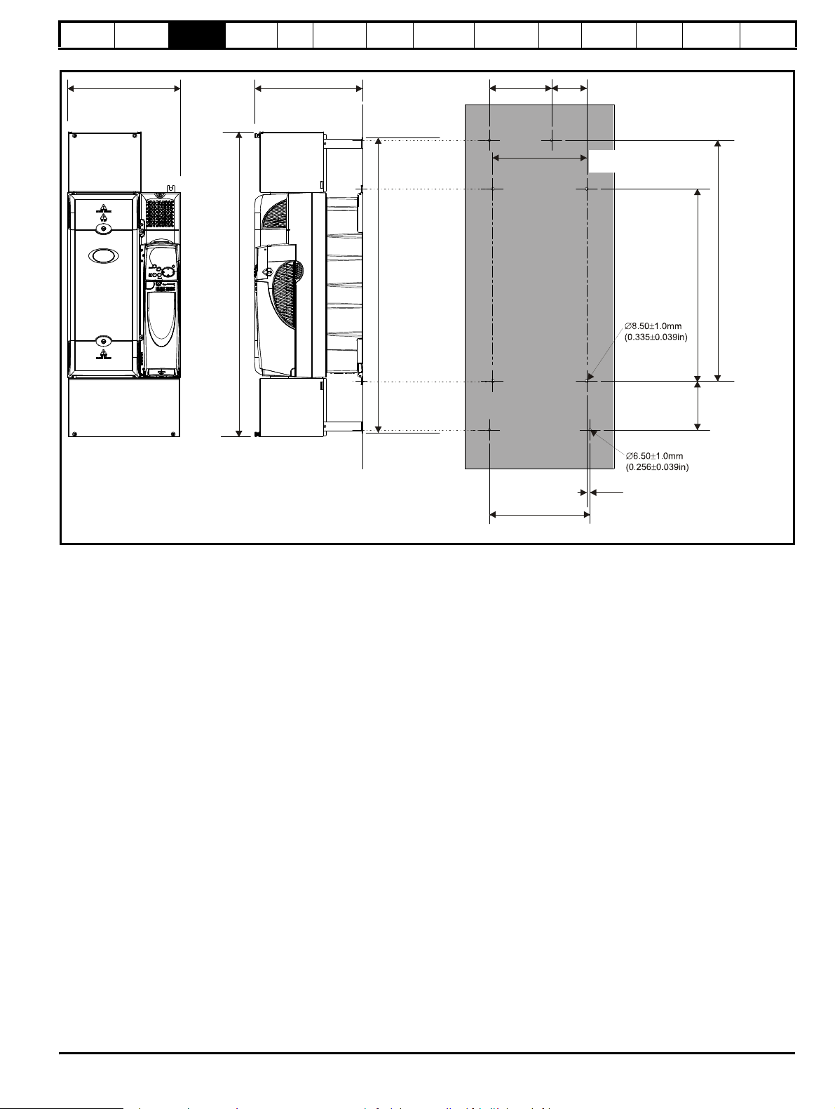
Safety
297.0mm (11.704in)
839mm
(33.046in)
310.0mm (12.204in)
812.0mm
(31.951in)
171.0±1.0mm
(6.732±0.039in)
96.8
±
±
1.0mm
(3.811 0.039in)
258.6
±
±
1.0mm
(10.181 0.039in)
662.8
±
±
1.0mm
(26.094 0.039in)
528.8
±±1.0mm
(20.819 0.039in)
134.0
±
±
1.0mm
(5.276 0.039in)
9.20
±
±
1.0mm
(0.362 0.039in)
277.0
±
±
1.0mm
(10.906 0.039in)
Information
Product
Information
Mechanical
Installation
Electrical
Installation
Getting
Star ted
Basic
parameters
Running
the motor
Optimization
SMARTCARD
operation
PC tools
Figure 3-22 Surface mounting the standard size 4 drive with conduit connection boxes installed
Advanced
parameters
Technical
Data
Diagnostics
UL Listing
Information
Affinity User Guide 33
Issue Number: 5 www.controltechniques.com
Page 34

Safety
310.0mm (12.202in)
296.0mm (11.671in)
1150.0mm
(45.270in)
258.6
±
±
1.0mm
(10.181 0.039in)
1122.0mm
(44.175in)
839.3
±
±
1.0mm
(33.043 0.039in)
973.3 1.0mm
(38.319 0.039in)
±
±
134.0 1.0mm
(5.276 0.039in)
±
±
9.20
±
±
1.0mm
(0.362 0.039in)
277.0
±
±
1.0mm
(10.906 0.039in)
Information
Product
Information
Mechanical
Installation
Electrical
Installation
Getting
Star ted
Basic
parameters
Running
the motor
Optimization
SMARTCARD
operation
PC tools
Figure 3-23 Surface mounting the standard size 5 drive with conduit connection boxes installed
Advanced
parameters
Technical
Data
Diagnostics
UL Listing
Information
34 Affinity User Guide
www.controltechniques.com Issue Number: 5
Page 35
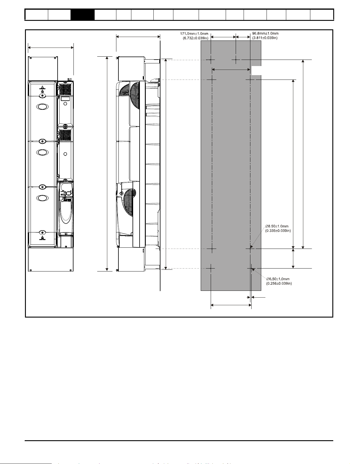
Safety
310.0mm (12.202in)
1460.0mm
(57.467in)
298.0mm (11.729in)
1433.0mm
(56.400in)
258.6
±
±
1.0mm
(10.181 0.039in)
115 0.8
±±1.0mm
(45.307 0.039in)
1284.8
±±1.0mm
(50.583 0.039)
133.0
±
±
1.0mm
(5.236 0.039in)
277.0
±
±
1.0mm
(10.906 0.039in)
9.20
±
±
1.0mm
(0.362 0.039in)
Information
Product
Information
Mechanical
Installation
Electrical
Installation
Getting
Star ted
Basic
parameters
Running
the motor
Optimization
SMARTCARD
operation
PC tools
Figure 3-24 Surface mounting the standard size 6 drive with conduit connection boxes installed
Advanced
parameters
Technical
Data
Diagnostics
UL Listing
Information
Affinity User Guide 35
Issue Number: 5 www.controltechniques.com
Page 36

Safety
NOTE
100mm
(3.973in)
368mm
(14.488in)
391mm
(15.394in)
219mm (8.622in)
80mm
(3.150in)
342mm
(13.465in)
343.0 0 .5mm
(13.504 0.020in)
±
±
368.0 1.0mm
(14.488 0.039in)
±
±
9.4 0.75mm
(0.370 0.030in)
±
±
70.0 0.3mm
(2.756 0.012in)
±
±
93.0 0.5mm
(3.661 0.020in)
±
±
35.0 .15mm
(1.378 0.006in)
±0
±
139mm (5.472in)
∅
6.5mm
(0.256in)
∅
6.5mm
(0.256in)
15.6 0.5mm
(0.614 0.020in)
±
±
Information
Product
Information
Mechanical
Installation
Electrical
Installation
Getting
Star ted
Basic
parameters
Running
the motor
3.5.2 Standard drive through-panel mounting
When the standard drive is through-panel mounted, the main terminal
cover(s) must be removed in order to provide access to the mounting
holes. Once the drive has been mounted, the terminal cover(s) can be
replaced.
The conduit connection box cannot be used when through-panel
mounting the standard drive‘
In order to achieve IP54 rating (UL Type 12 / NEMA 12) for throughpanel mounting, an IP54 insert must be installed (size 1 and 2) and the
heatsink fan should be replaced with an IP54 rated fan (sizes 1 to 4).
Additionally, the gasket provided should be installed between the drive
and the backplate to ensure a good seal for the enclosure. If the
heatsink mounted braking resistor is to be used with the drive throughpanel mounted, refer to the specific Braking resistor installation sheet.
For further information refer to section 3.8 Enclosing standard drive for
high environmental protection on page 50.
Figure 3-25 Through-panel mounting the standard size 1 drive
Optimization
SMARTCARD
operation
PC tools
Advanced
parameters
Technical
Data
Diagnostics
UL Listing
Information
36 Affinity User Guide
www.controltechniques.com Issue Number: 5
Page 37

Safety
368mm
(14.488in)
391mm
(15.394in)
155mm (6.102in)
219mm (8.622in)
139mm (5.472in)
293mm
(11.535in)
9.3 0.5mm
(0.366 0.020in)
±
±
101.5 0.5mm
(3.996 0.020in)
±
±
64.6 0.5mm
(2.543 0.020in)
±
±
70 0.3mm
(2.756 0.012in)
±
±
148 0.5mm
(5.827 0.020in)
±
±
294 0.5mm
(11.575 0.020in)
±
±
368.0 1.0mm
(14.488 0.039in)
±
±
∅
6.5mm
(0.256in)
∅
6.5mm
(0.256in)
35.0 0.15mm
(1.378 0.006in)
±
±
80mm
(3.150in)
250mm(9.843in)
368mm
(14.488in)
140mm (5.512in) 120mm (4.724in)
260mm (10.236in)
283mm
(11.142in)
236 0.5mm
(9.291 0.020in)
±
±
287 0.5mm
(11.299 0.020in)
±
±
80.3mm
(0.315 0.012in)
±
±
56 0.5mm
(2.205 0.020in)
±
±
∅
6.5mm
(0.256in)
∅
6.5mm
(0.256in)
Information
Product
Information
Mechanical
Installation
Electrical
Installation
Getting
Star ted
Basic
parameters
Running
the motor
Figure 3-26 Through-panel mounting the standard size 2 drive
Optimization
SMARTCARD
operation
PC tools
Advanced
parameters
Technical
Data
Diagnostics
UL Listing
Information
Figure 3-27 Through-panel mounting the standard size 3 drive
Affinity User Guide 37
Issue Number: 5 www.controltechniques.com
Page 38

Safety
310mm (12.205in)
510mm
(20.079in)
298mm (11.732in)
200mm (7.874in)
98mm
(3.858in)
540.3
0.5mm
(21.272
0.020in)
±
±
258.6 0.5mm
(10.181 0.020in)
±
±
286.0 0 .5mm
(11.260 0.020in)
±
±
487.0 0 .5mm
(19.173 0.020in)
±
±
484mm
(19.055in)
258.6 0.5mm
(10.181 0.020in)
±
±
14.2
0.5mm
0.559 0.020in)
±
±
26.65
0.5mm
1.049 0.020in)
±
±
558mm
(21.969in)
∅
8.5mm
(0.335in)
∅
8.5mm
(0.335in)
R6.5mm
(0.256in)
R6.5mm
(0.256in)
Information
Product
Information
Mechanical
Installation
Electrical
Installation
Getting
Star ted
Basic
parameters
Running
the motor
Figure 3-28 Through-panel mounting the standard size 4 drive
Optimization
SMARTCARD
operation
PC tools
Advanced
parameters
Technical
Data
Diagnostics
UL Listing
Information
When a size 4 is through-panel mounted, the grounding link bracket
must be folded upwards. This is required to provide a grounding point for
the grounding bracket. See section 4.11.1 Grounding hardware on
page 79 for more information.
38 Affinity User Guide
www.controltechniques.com Issue Number: 5
Page 39

Safety
310mm (12.205in)
258.6 0.5mm
(10.181 0.020inm)
±
±
14.2 0.5mm
(0.559 0.020in)
±
±
286.0 0.5mm
(11.260 0.020in)
±
±
852.6
0.5mm
(33.567
0.020in)
±
±
258.6 0.5mm
(10.181 0.020in)
±
±
26.7 0.5mm
(1.051 0.020in)
±
±
797.5 0.5mm
(31.398 0.020in)
±
±
794.5mm
(31.280in)
298mm (11.732in)
200mm (7.874in)
98mm
(3.858in)
820mm
(32.283in)
868mm
(34.173in)
∅
8.5mm
(0.335in)
∅
8.5mm
(0.335in)
R6.5mm
(0.256in)
R6.5mm
(0.256in)
Information
Product
Information
Mechanical
Installation
Electrical
Installation
Getting
Star ted
Basic
parameters
Running
the motor
Figure 3-29 Through-panel mounting the standard size 5 drive
Optimization
SMARTCARD
operation
PC tools
Advanced
parameters
Technical
Data
Diagnostics
UL Listing
Information
When a size 5 is through-panel mounted, the grounding link bracket
must be folded upwards. This is required to provide a grounding point for
the grounding bracket. See section 4.11.1 Grounding hardware on
page 79 for more information.
Affinity User Guide 39
Issue Number: 5 www.controltechniques.com
Page 40
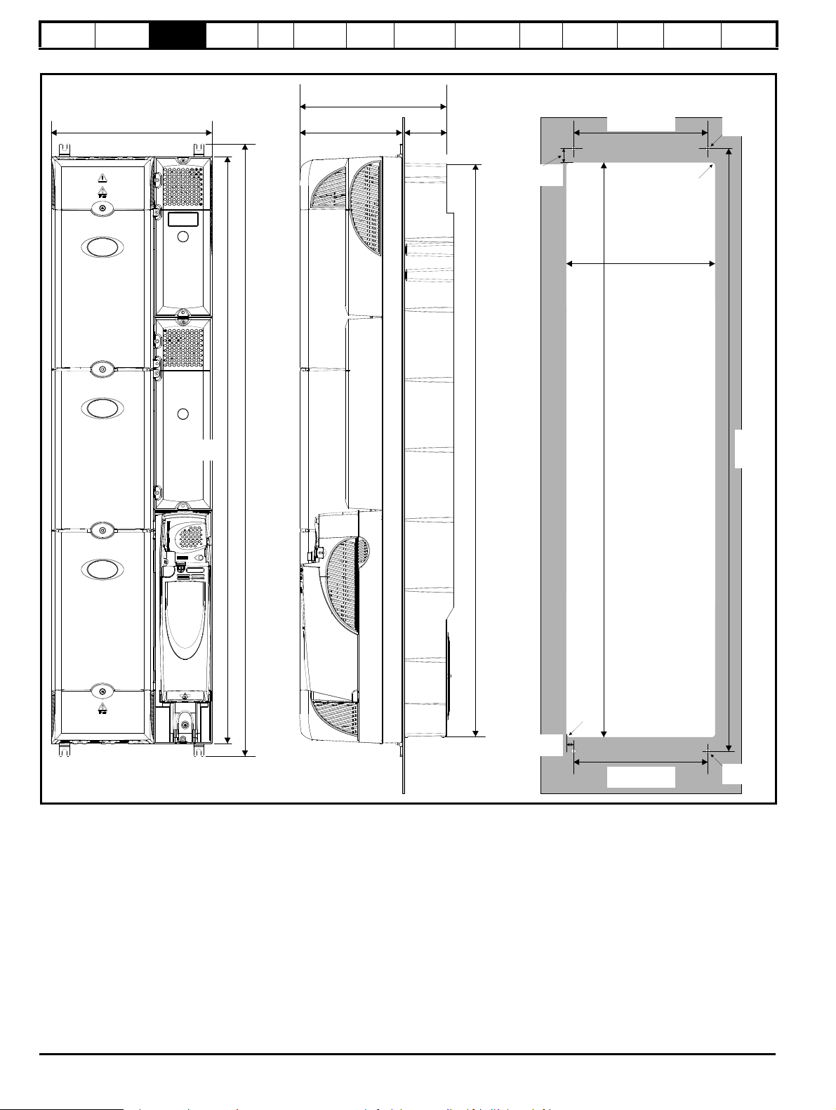
Safety
310mm (12.205in) 200mm (7.874in)
1105.6mm
(43.528in)
∅
8.5mm
(0.335in)
∅
8.5mm
(0.335in)
1131mm
(44.528in)
1179.3mm
(46.429in)
98mm
(3.858in)
298mm (11.732in)
258.6 0.5mm
(10.181 0.020in)
±
±
286.0 0.5mm
(11.260 0.020in)
±
±
1107.8 0.5mm
(43.614 0.020in)
±
±
27.1 0.5mm
(1.067 0.020in)
±
±
13.7±±0.5mm
(0.539 0.020in)
258.6 0.5mm
(10.181 0.020in)
±
±
1161.2
0.5mm
(45.717
0.020in)
±
±
R6.5mm
(0.256in)
R6.5mm
(0.256in)
Information
Product
Information
Mechanical
Installation
Electrical
Installation
Getting
Star ted
Basic
parameters
Running
the motor
Figure 3-30 Through-panel mounting the standard size 6 drive
Optimization
SMARTCARD
operation
PC tools
Advanced
parameters
Technical
Data
Diagnostics
UL Listing
Information
40 Affinity User Guide
www.controltechniques.com Issue Number: 5
Page 41

Safety
Short section
Long section
Short section
Long section
Information
3.5.3 Standard drive surface and through-panel
Product
Information
Mechanical
Installation
Electrical
Installation
Getting
Star ted
Basic
parameters
Running
the motor
Optimization
Figure 3-33 Location of top surface mounting brackets for size 5 and 6
mounting brackets
Table 3-2 Mounting brackets (Standard)
Model
size
Surface Through-panel
1x2x1
Hole
size
SMARTCARD
operation
PC tools
Advanced
parameters
Technical
Data
Diagnostics
UL Listing
Information
2x2x1
6.5mm
(0.256in)
3.5.5 E12/E54 drive surface mounting
Table 3-3 states the mounting clearances required when mounting the
E12/54 drive. The drive spacing stated for sizes 4 to 6 are recommended
3x2
to allow easy access to the maintainable dust filters. When installing the
drives, access to the filters should not be blocked by cabling or conduit.
For details on how to access the filters please refer to section
4
x4
3.11.1 E12/E54 filter change on page 64.
Table 3-3 E12/E54 mounting clearances
8.5mm
x4
(0.335in)
5 & 6
x2
To avoid damaging the through-panel mounting bracket when throughpanel mounting a size 1 or size 2, the through-panel mounting bracket
should be used to mount the top of the drive to the back plate before the
bottom of the drive is mounted to the back plate. The tightening torque
should be 4 N m (2.9 lb ft).
3.5.4 Installation of the mounting bracket on size 4, 5 and 6
Size 4, 5 and 6 use the same mounting brackets for surface and
through-panel mounting.
The mounting bracket has a long section and a short section.
Figure 3-31 Size 4, 5 and 6 mounting bracket
Clearances required at
Size
top and bottom of drive
mm
1 to 3 100
5 and 6 220
Clearances required at
side of drive
mm
204 150
The mounting bracket must be installed in the correct orientation with the
long section inserted into or attached to the drive and the short section is
attached to the back plate. Figure 3-32 shows the orientation of the
mounting bracket when the drive is surface and through-panel mounted.
Figure 3-32 Orientation of the size 4, 5 and 6 mounting bracket
When through-panel mounted, the mounting brackets on the left hand
side of the drive can be secured using the screws already located there.
On the right hand side, the mounting brackets are just inserted into the
slots in the chassis of the drive; no mounting screws are present here.
Size 5 and 6 also require two top mounting brackets when the drive is
surface mounted. The two brackets should be installed to the top of the
drive as shown in Figure 3-33.
The maximum torque setting for the screws into the drive chassis is
10 N m (7.4 lb ft).
Affinity User Guide 41
Issue Number: 5 www.controltechniques.com
Page 42
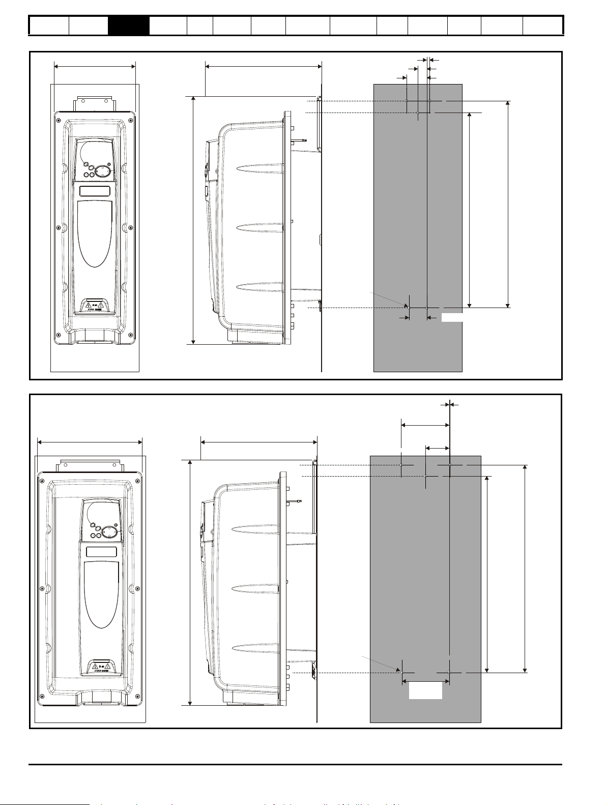
Safety
184.0mm (7.24in)
560.1mm
(22.05in)
263.7mm (10.38in)
6.0mm (0.24in)
20.0mm (0.79in)
46.0mm (1.81in)
441.0mm
17.35in
467.0mm
18.39in
∅
6.50mm
(0.26in)
40.0mm (1.56in)
236.0mm (9.29in)
552.3mm
(21.74in)
261.9mm (10.31in)
108.0mm
(4.252in)
53.0mm
(2.09in)
2.0mm
(0.8in)
442.0mm
(17.40in)
467.0mm
(18.39in)
∅
6.50mm
(0.26in)
106.0mm
(4.17in)
Information
Product
Information
Mechanical
Installation
Electrical
Installation
Getting
Star ted
Basic
parameters
Running
the motor
Figure 3-34 Size 1 E12/E54 and E12/E66 drive surface mounting
Optimization
SMARTCARD
operation
PC tools
Advanced
parameters
Technical
Data
Diagnostics
UL Listing
Information
Figure 3-35 Size 2 E12/E54 and E12/E66 drive surface mounting
42 Affinity User Guide
www.controltechniques.com Issue Number: 5
Page 43

Safety
331.3mm (13.04in)
543.6mm
(21.40in)
302.0mm (11.89in)
108.0mm
(4.252in)
53.0mm
(2.09in)
2.0mm
(0.8in)
434.0mm
(17.09in)
459.0mm
(18.07in)
∅
6.50mm
(0.26in)
106.0mm
(4.17in)
703mm
(27.71in)
386mm (15.2in) 346mm (13.62in) 253.6mm (9.98in)
573.4
(22.57in)
∅
8.5mm
(0.33in)
Information
Product
Information
Mechanical
Installation
Electrical
Installation
Getting
Star ted
Basic
parameters
Running
the motor
Figure 3-36 Size 3 E12/E54 and E12/E66 drive surface mounting
Optimization
SMARTCARD
operation
PC tools
Advanced
parameters
Technical
Data
Diagnostics
UL Listing
Information
Figure 3-37 Size 4 E12/E54 drive surface mounting
Affinity User Guide 43
Issue Number: 5 www.controltechniques.com
Page 44

Safety
416mm (16.38in)
1211.4mm
(14.69in)
347.2mm (13.67in)
253.6mm (9.98in)
883.9mm
(34.8in)
∅
8.5mm
(0.34in)
Information
Product
Information
Mechanical
Installation
Electrical
Installation
Getting
Star ted
parameters
Figure 3-38 Size 5 E12/E54 drive surface mounting
Basic
Running
the motor
Optimization
SMARTCARD
operation
PC tools
Advanced
parameters
Technical
Data
Diagnostics
UL Listing
Information
44 Affinity User Guide
www.controltechniques.com Issue Number: 5
Page 45
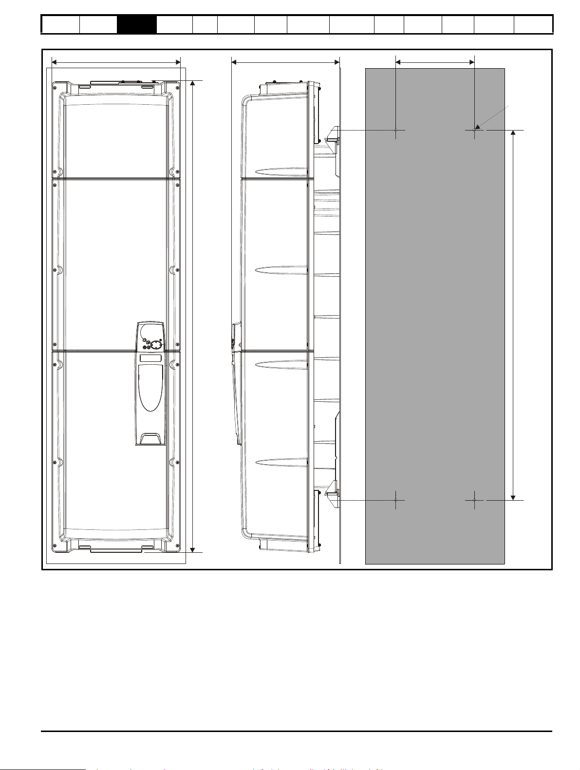
Safety
416mm (16.38in)
348.1mm (13.7in)
253.6mm (9.98in)
1522.9mm
(59.96in)
1194.4mm
(47.02in)
∅
8.5mm
(0.34in)
Information
Product
Information
Mechanical
Installation
Electrical
Installation
Getting
Star ted
parameters
Figure 3-39 Size 6 E12/E54 drive surface mounting
Basic
Running
the motor
Optimization
SMARTCARD
operation
PC tools
Advanced
parameters
Technical
Data
Diagnostics
UL Listing
Information
Affinity User Guide 45
Issue Number: 5 www.controltechniques.com
Page 46
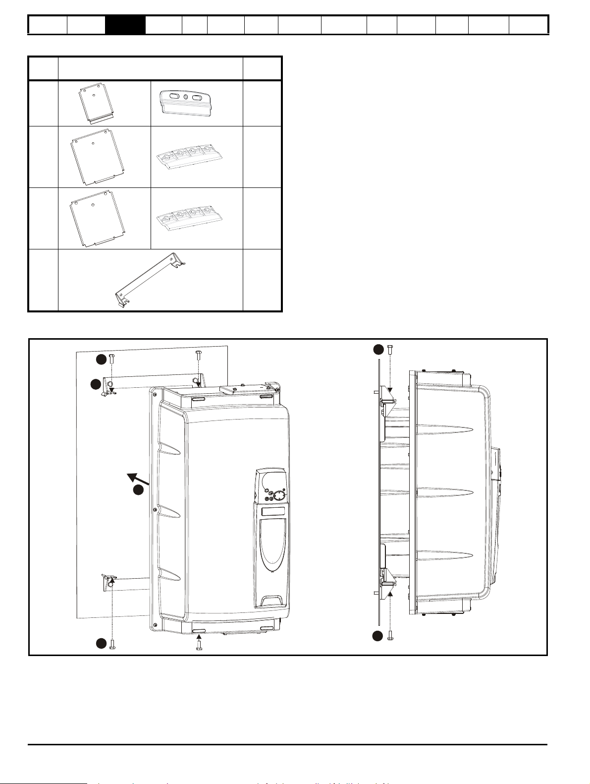
Safety
1
2
3
333
Information
Table 3-4 E12/E54 mounting brackets
Model
size
Product
Information
Mechanical
Installation
Electrical
Installation
E12/E54 surface mounting brackets
Getting
Star ted
Basic
parameters
Running
the motor
Hole
size
Optimization
SMARTCARD
Only two of the brackets illustrated in Table 3-4 are required when
surface mounting the E12/E54 drive. It is recommended as standard that
one of each type is used as illustrated in Figure 3-34, Figure 3-35, Figure
3-36. However, if the E12/E54 drive is to be footprint mounted to an
external EMC filter, both the smaller surface mounting brackets should
be used.
1x1x2M6
2x1x2M6
3x1x2M6
4, 5, 6 x2 M8
operation
PC tools
Advanced
parameters
Technical
Data
Diagnostics
UL Listing
Information
Mounting the size 4 to 6 E12/54 drive
Figure 3-40 Mounting option 1
1. Bolt the two mounting brackets to the enclosure wall.
2. Manoeuvre the drive so it fits between the two mounting brackets
3. Use the M8 bolts provided to secure the drive to the mounting
brackets (10 N m [7.4 lb ft]).
46 Affinity User Guide
www.controltechniques.com Issue Number: 5
Page 47
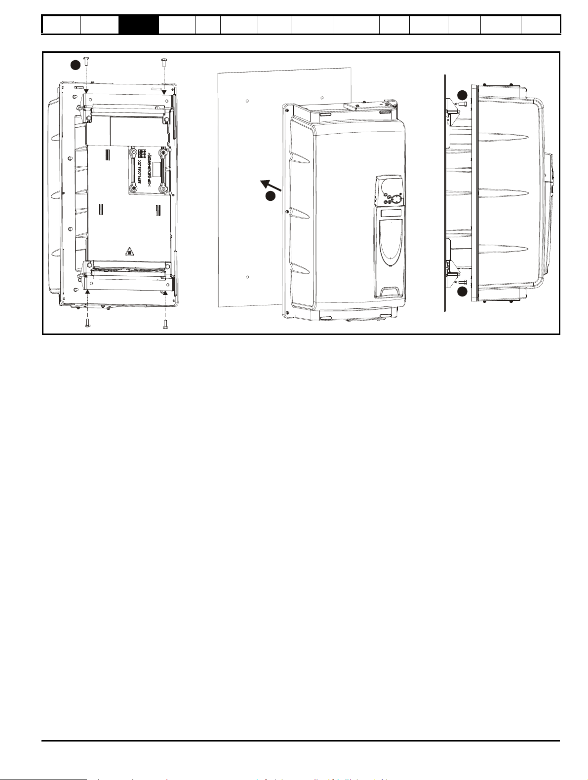
Safety
1
2
3
3
Information
Product
Information
Mechanical
Installation
Figure 3-41 Mounting option 2
Electrical
Installation
Getting
Star ted
Basic
parameters
Running
the motor
Optimization
SMARTCARD
operation
PC tools
Advanced
parameters
Technical
Data
Diagnostics
UL Listing
Information
1. Use the M8 bolts provided to secure the mounting brackets to the
drive (10 N m [7.4 lb ft]).
2. Once appropriate holes have been drilled into the back plate, line up
the drive accordingly.
3. Bolt the drive to the backplate through the mounting brackets
already secured to the drive.
Affinity User Guide 47
Issue Number: 5 www.controltechniques.com
Page 48

Safety
≥
100mm
(4in)
Enclosure
AC supply
contactor and
fuses or MCB
Locate as
required
Locate as
required
External
controller
Signal cables
Plan for all signal cables
to be routed at least
300mm (12in) from the
drive and any power cable
Ensure minimum clearances
are maintained for the drive
and external EMC filter. Forced
or convection air-flow must not
be restricted by any object or
cabling
≥
100mm
(4in)
Optional braking resistor and overload
Locate optional braking
resistor external to
cubicle (preferably near to or
on top of the cubicle).
Locate the overload protection
device as required
The external EMC filter can be
bookcase mounted (next to the
drive) or footprint mounted (with
the drive mounted onto the filter).
Note
For EMC compliance:
1) When using an external EMC
filter, one filter is required for
each drive
2) Power cabling must be at
least 100mm (4in) from the
drive in all directions
A
A
Size 1: 0mm (0in)
Sizes 2 to 6: 30mm (1.181in)
≥
≥
A
A
e
P
kT
intText
–()
-----------------------------------=
Information
Product
Information
Mechanical
Installation
Electrical
Installation
Getting
Star ted
Basic
parameters
Running
the motor
Optimization
SMARTCARD
operation
PC tools
Advanced
parameters
Technical
Data
Diagnostics
UL Listing
Information
3.6 Enclosure for standard drives
3.6.1 Enclosure layout
Please observe the clearances in the diagram below taking into account any appropriate notes for other devices / auxiliary equipment when planning
the installation.
Figure 3-42 Enclosure layout
3.6.2 Enclosure sizing
1. Add the dissipation figures from section 12.1.2 Power dissipation on
page 233 for each drive that is to be installed in the enclosure.
2. If an external EMC filter is to be used with each drive, add the
dissipation figures from section 12.2.1 EMC filter ratings on
page 247 for each external EMC filter that is to be installed in the
enclosure.
3. If the braking resistor is to be mounted inside the enclosure, add the
average power figures from for each braking resistor that is to be
installed in the enclosure.
4. Calculate the total heat dissipation (in Watts) of any other equipment
to be installed in the enclosure.
5. Add the heat dissipation figures obtained above. This gives a figure
in Watts for the total heat that will be dissipated inside the enclosure.
Calculating the size of a sealed enclosure
The enclosure transfers internally generated heat into the surrounding
air by natural convection (or external forced air flow); the greater the
surface area of the enclosure walls, the better is the dissipation
capability. Only the surfaces of the enclosure that are unobstructed (not
in contact with a wall or floor) can dissipate heat.
Calculate the minimum required unobstructed surface area A
enclosure from:
48 Affinity User Guide
for the
e
www.controltechniques.com Issue Number: 5
Where:
A
Unobstructed surface area in m2 (1 m2 = 10.9 ft2)
e
T
Maximum expected temperature in
ext
o
C outside the
enclosure
Maximum permissible temperature in oC inside the
T
int
enclosure
P Power in Watts dissipated by all heat sources in the
Example
To calculate the size of an enclosure for the following:
enclosure
k Heat transmission coefficient of the enclosure material
2/o
in W/m
C
• Two BA1406 models operating at the Normal Duty rating
• Each drive to operate at 6kHz PWM switching frequency
• Schaffner 16 A (4200-6119) external EMC filter for each drive
• Braking resistors are to be mounted outside the enclosure
• Maximum ambient temperature inside the enclosure: 40°C
• Maximum ambient temperature outside the enclosure: 30°C
Page 49

Safety
W
H
D
A
e
392.4
5.5 40 30–()
---------------------------------=
W
A
e
2HD–
HD+
--------------------------=
W
7.135 2 2× 0.6×()–
20.6+
-----------------------------------------------------=
V
3kP
T
intText
–
---------------------------=
P
o
P
l
-------
V
31.3× 323.7×
40 30–
---------------------------------------=
Information
Product
Information
Mechanical
Installation
Electrical
Installation
Getting
Star ted
Basic
parameters
Running
the motor
Dissipation of each drive: 187 W (see section 12-8 Summary of drive
losses tables on page 233)
Dissipation of each external EMC filter: 9.2 W (max) (see section
12.2.1 EMC filter ratings on page 247)
Total dissipation: 2 x (187 + 9.2) =392.4 W
The enclosure is to be made from painted 2 mm (0.079 in) sheet steel
2/o
having a heat transmission coefficient of 5.5 W/m
C. Only the top,
front, and two sides of the enclosure are free to dissipate heat.
The value of 5.5 W/m
2
/ºC can generally be used with a sheet steel
enclosure (exact values can be obtained by the supplier of the material).
If in any doubt, allow for a greater margin in the temperature rise.
Figure 3-43 Enclosure having front, sides and top panels free to
dissipate heat
Insert the following values:
T
40°C
int
30°C
T
ext
k 5.5
P 392.4 W
The minimum required heat conducting area is then:
Optimization
SMARTCARD
operation
PC tools
Advanced
parameters
Technical
Data
Diagnostics
Where:
3
V Air-flow in m
T
Maximum expected temperature in °C outside the
ext
per hour (1 m3/hr = 0.59 ft3/min)
enclosure
T
Maximum permissible temperature in °C inside the
int
enclosure
P Power in Watts dissipated by all heat sources in the
enclosure
k Ratio of
Where:
P
is the air pressure at sea level
0
is the air pressure at the installation
P
I
Typically use a factor of 1.2 to 1.3, to allow also for pressure-drops in
dirty air-filters.
Example
To calculate the size of an enclosure for the following:
• Three BA1403 models operating at the Normal Duty rating
• Each drive to operate at 6kHz PWM switching frequency
• Schaffner 10A (4200-6118) external EMC filter for each drive
• Braking resistors are to be mounted outside the enclosure
• Maximum ambient temperature inside the enclosure: 40°C
• Maximum ambient temperature outside the enclosure: 30°C
Dissipation of each drive: 101 W
Dissipation of each external EMC filter: 6.9 W (max)
Total dissipation: 3 x (101 + 6.9) = 323.7 W
Insert the following values:
40°C
T
int
30°C
T
ext
k 1.3
P 323.7 W
Then:
UL Listing
Information
2
= 7.135 m
(77.8 ft2) (1 m2 = 10.9 ft2)
Estimate two of the enclosure dimensions - the height (H) and depth (D),
for instance. Calculate the width (W) from:
Inserting H = 2m and D = 0.6m, obtain the minimum width:
=1.821 m (71.7 in)
If the enclosure is too large for the space available, it can be made
smaller only by attending to one or all of the following:
• Using a lower PWM switching frequency to reduce the dissipation in
the drives
• Reducing the ambient temperature outside the enclosure, and/or
applying forced-air cooling to the outside of the enclosure
• Reducing the number of drives in the enclosure
• Removing other heat-generating equipment
Calculating the air-flow in a ventilated enclosure
The dimensions of the enclosure are required only for accommodating
the equipment. The equipment is cooled by the forced air flow.
Calculate the minimum required volume of ventilating air from:
= 126.2 m
3
/hr (74.5 ft3 /min) (1 m3/ hr = 0.59 ft3/min)
3.7 Enclosure design and drive ambient temperature
Drive derating is required for operation in high ambient temperatures
Totally enclosing or through panel mounting the drive in either a sealed
cabinet (no airflow) or in a well ventilated cabinet makes a significant
difference on drive cooling.
The chosen method affects the ambient temperature value (T
should be used for any necessary derating to ensure sufficient cooling
for the whole of the drive.
The ambient temperature for the four different combinations is defined
below:
1. Totally enclosed with no air flow (<2 m/s) over the drive
T
= T
rate
+ 5°C
int
2. Totally enclosed with air flow (>2 m/s) over the drive
T
= T
rate
int
3. Through panel mounted with no airflow (<2 m/s) over the drive
T
= the greater of T
rate
+5°C, or T
ext
int
4. Through panel mounted with air flow (>2 m/s) over the drive
T
= the greater of T
rate
ext
or T
int
Where:
T
= Temperature outside the cabinet
ext
= Temperature inside the cabinet
T
int
= Temperature used to select current rating from tables in
T
rate
Chapter 12 Technical data .
rate
) which
Affinity User Guide 49
Issue Number: 5 www.controltechniques.com
Page 50

Safety
IP20
(NEMA1)
IP54 (UL Type 12 / NEMA 12)
enclosure
Drive with
IP54 insert
and IP54
fan installed
Gasket
seal
Drive
Gasket
Enclosure
rear wall
Information
Product
Information
Mechanical
Installation
Electrical
Installation
Getting
Star ted
Basic
parameters
Running
the motor
3.8 Enclosing standard drive for high environmental protection
An explanation of environmental protection rating is provided in section
12.1.9 Environmental Protection Rating on page 239.
The standard drive is rated to IP20 pollution degree 2 (dry, nonconductive contamination only) (UL Type 1 / NEMA 1). However, it is
possible to configure the drive to achieve IP54 rating (UL Type 12 /
NEMA 12) at the rear of the heatsink for through-panel mounting (some
current derating is required for size 1 and 2). Refer to Table 12-2 on
page 229.
This allows the front of the drive, along with various switchgear, to be
housed in an IP54 (UL Type 12 / NEMA 12) enclosure with the heatsink
protruding through the panel to the external environment. Thus, the
majority of the heat generated by the drive is dissipated outside the
enclosure maintaining a reduced temperature inside the enclosure. This
also relies on a good seal being made between the heatsink and the rear
of the enclosure using the gaskets provided.
For Type 12 the drive must be mounted on a flat surface of a Type
12 enclosure.
Figure 3-44 Example of IP54 (UL Type 12 / NEMA 12) through-
panel layout
Optimization
SMARTCARD
operation
PC tools
Figure 3-45 Installing the gasket
Advanced
parameters
Technical
Data
Diagnostics
UL Listing
Information
The main gasket should be installed as shown in Figure 3-45. Any
screws / bolts that are used for mounting should be installed with the
nylon washers provided in the kit box to maintain a seal around the
screw hole. See Figure 3-48.
In order to achieve the high IP rating at the rear of the heatsink with size
1 and 2, it is necessary to seal a heatsink vent by installing the IP54
insert as shown in Figure 3-46 and Figure 3-47.
50 Affinity User Guide
www.controltechniques.com Issue Number: 5
Page 51

Safety
2
3
4
5
6
7
Remove metal clip (1).
Push tab in the direction
shown (2) and lift hinged
baffle as shown (3)
Remove IP54 insert from
hinged baffle by releasing
clip (4).
Rotate the IP54 insert
through 180 so that the
flat side faces away from
the fan (5).
Lower IP54 insert into
position as shown (7).
o
Remove the backing from
the IP54 insert gasket and
stick it into the recess of
the IP54 insert (6). (The
gasket can be found in
the accessories box.)
IP54 insert
Close hinged baffle (8)
and click into position.
Replace metal clip (9).
1
9
IP54 insert
gasket
8
Push plastic tabs in the
direction shown (1).
Push tab in the direction
shown (2), and lift hinged
baffle as shown (3).
Take IP54 insert from
the accessories box (4).
Lower the IP54 insert into
the ventilation hole in the
heatsink (5).
Close hinged baffle (6)
and click into position,
ensuring tabs locate
correctly.
2
3
5
4
6
1
1
Information
Product
Information
Mechanical
Installation
Electrical
Installation
Getting
Star ted
Figure 3-46 Installation of IP54 insert for size 1
Basic
parameters
Running
the motor
Optimization
SMARTCARD
operation
PC tools
Advanced
parameters
Technical
Figure 3-47 Installation of IP54 insert for size 2
Data
Diagnostics
UL Listing
Information
In order to remove the IP54 insert, repeat steps (1), (2) and (3), reverse
steps (7), (6), (5) and (4) and repeat steps (8) and (9).
Affinity User Guide 51
Issue Number: 5 www.controltechniques.com
In order to remove the IP54 insert, repeat steps (1) (2) and (3), reverse
steps (5) and (4) and repeat step (6).
Page 52
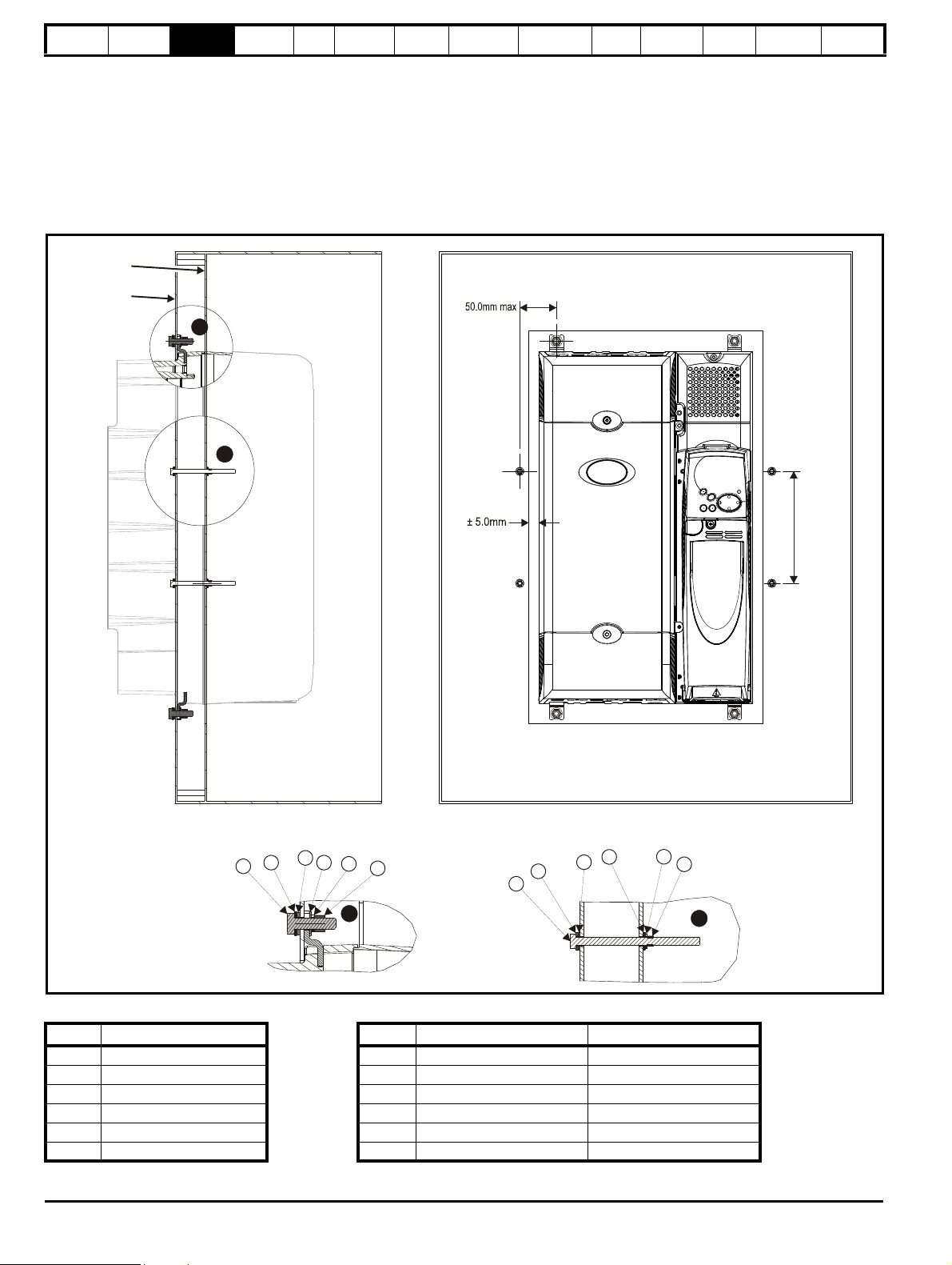
Safety
Holes equispaced along length of drive
Backplate
Enclosure
rear wall
A
B
A
1
2
3
4
5
6
12345
6
BM8M6
Information
For sizes 4 to 6 it may be necessary to improve the rigidity of the through
panel mounting surface due to the larger distance between the top and
bottom mounting brackets and the need to maintain compression on the
gasket.
When the drive is mounted, if the gap between the drive flange (which
the gasket rests on) and the rear wall of the enclosure is ≥6mm at any
point around the drive then the following methods can be used to
compress the gasket further:
Product
Information
Mechanical
Installation
Electrical
Installation
Getting
Star ted
Basic
parameters
Running
the motor
Optimization
SMARTCARD
operation
1. Use a thicker panel for the mounting wall of the enclosure through
which the drive is mounted.
2. Use an internal backplate to pull the rear wall of the enclosure up to
the drive gasket. See Figure 3-48 for details. (Nylon washers are
supplied in the standard drive kit for sealing off any nut and bolt
mountings that exit through the rear wall of the panel).
3. If an internal backplate is not available a separate clamp can be
used to simulate option 2. See Figure 3-49. 4 off sealing clamps are
supplied in the drive kit box.
Figure 3-48 Option 2 for achieving IP54 (UL type 12 / NEMA 12) through-panel mounting
PC tools
Advanced
parameters
Technical
Data
Diagnostics
UL Listing
Information
Table 3-5 Description of fixings Table 3-6 Quantity of nylon washers supplied with the drive
Item Description Size Quantity of M8 (A) Quantity of M6 (B)
1Bolt 1 0 3
2 Flat washer 2 0 3
3 Nylon washer (from kitbox) 3 0 4
4 Flat washer 4 4 4
5 Spring washer 5 4 4
6Nut 6 4 4
52 Affinity User Guide
www.controltechniques.com Issue Number: 5
Page 53

Safety
Sealing
bracket
(4 places)
Enclosure
rear wall
NOTE
NOTE
Information
Product
Information
Mechanical
Installation
Electrical
Installation
Getting
Star ted
Basic
parameters
Running
the motor
Optimization
SMARTCARD
operation
Figure 3-49 Option 3 for achieving IP54 (UL Type 12 / NEMA 12) through panel mounting
PC tools
Advanced
parameters
Technical
Data
Diagnostics
UL Listing
Information
For increased fan lifetime in a dirty environment the heatsink fan must be
replaced with an IP54 rated fan. Contact the supplier of the drive for
details. If the standard fan is used in a dirty/dusty environment, reduced
fan lifetime will result. Regular cleaning of the fan and heatsink is
recommended in this environment. The heatsink fan installed in sizes 5
and 6 are IP54 rated as standard.
The guidelines in Table 3-7 should be followed.
Table 3-7 Environment considerations
Environment
Clean
Dry, dusty (nonconductive)
Dry, dusty
(conductive)
IP54
Insert
Not
installed
Installed Standard
Installed
IP54 compliance Installed IP54
Fan Comments
Standard
Regular cleaning
recommended. Fan lifetime
may be reduced.
Standard /
IP54
Regular cleaning
recommended. Fan lifetime
may be reduced.
Regular cleaning
recommended.
A current derating must be applied to the size 1 and 2 if the IP54 insert
and/or IP54 rated fan are installed. Derating information is provided in
section 12.1.1 Power and current ratings (Derating for switching
frequency and temperature) on page 228.
Failure to do so may result in nuisance tripping.
Table 3-8 Power losses from the front of the drive when through-
panel mounted
Frame size Power loss
1 ≤50W
2 ≤75W
3 ≤100W
4 ≤204W
5 ≤347W
6 ≤480W
When designing an IP54 (UL Type 12 / NEMA 12) enclosure (Figure 3-
44), consideration should be made to the dissipation from the front of the
drive.
Affinity User Guide 53
Issue Number: 5 www.controltechniques.com
Page 54

Safety
NOTE
Information
Product
Information
Mechanical
Installation
Electrical
Installation
Getting
Star ted
Basic
parameters
Running
the motor
Optimization
SMARTCARD
operation
PC tools
Advanced
parameters
Technical
Data
Diagnostics
UL Listing
Information
3.9 External EMC filter for standard drives
In order to provide our customers with a degree of flexibility, external EMC filters have been sourced from two manufacturers: Schaffner & Epcos.
Filter details for each drive rating are provided in the tables below. Both the Schaffner and Epcos filters meet the same specifications.
Table 3-9 Drive EMC filter details (size 1 to 6)
Drive
CT part no. Weight CT part no. Weight CT part no. Weight
BA1201 to BA1202 4200-6118
BA1203 to BA1204 4200-6119 4200-6120 4200-6124 2.3 kg (5.1lb)
BA1401 to BA1404 4200-6118
BA1405 to BA1406 4200-6119 4200-6120 4200-6124 2.3 kg (5.1 lb)
BA2201 to BA2203 4200-6210 2.0 kg (4.4 lb) 4200-6211 3.3 kg (7.3 lb) 4200-6218 4.5 kg (9.9 lb)
BA2401 to BA2403 4200-6210 2.0 kg (4.4 lb) 4200-6211 3.3 kg (7.3 lb) 4200-6218 4.5 kg (9.9 lb)
BA3201 to BA3202 4200-6307 3.5 kg (7.7 lb) 4200-6306 5.1 kg (11.2 lb) 4200-6319 9.4 kg (20.7 lb)
BA4201 to BA4203 4200-6406 4.0 kg (8.8 lb) 4200-6405 7.8 kg (17.2 lb)
BA3401 to BA3403 4200-6305
BA3501 to BA3507 4200-6309 4200-6308 4200-6320 8.75 kg (19.3 lb)
BA4401 to BA4403 4200-6406 4.0 kg (8.8 lb) 4200-6405 7.8 kg (17.2 lb)
BA4601 to BA4606 4200-6408 3.8 kg (8.4 lb) 4200-6407 8.0 kg (17.6 lb)
BA5401 to BA5402 4200-6503 6.8 kg (15.0 lb) 4200-6501 12.0 kg (26.5 lb)
BA5601 to BA5602 4200-6504 4.4 kg (9.7 lb) 4200-6502 10.0 kg (22.0 lb)
BA6401 to BA6402 4200-6603
BA6601 to BA6602 4200-6604 4200-6602
The external EMC filters for sizes 1 to 3 can be footprint or bookcase mounted, see Figure 3-50 and Figure 3-51. The external EMC filters for sizes 4
to 6 are designed to be mounted above the drive, as shown in Figure 3-52.
Mount the external EMC filter following the guidelines in section 4.11.5 Compliance with generic emission standards on page 84.
Figure 3-50 Footprint mounting the EMC
filter
Schaffner IP20 Epcos IP20 Schaffner IP54
1.4 kg (3.1 lb)
1.4 kg (3.1 lb)
3.5 kg (7.7 lb)
5.25 kg (11.6 lb)
4200-6121
4200-6121
4200-6306
4200-6601
Figure 3-51 Bookcase mounting the EMC
filter
2.1 kg (4.6 lb)
2.1 kg (4.6 lb)
5.1 kg (11.2 lb)
8.6 kg (19.0 lb)
Figure 3-52 Size 4 to 6 mounting of EMC
4200-6125 2.25 kg (5.0lb)
4200-6125 2.25 kg (5.0 lb)
4200-6318 8.75 kg (19.3 lb)
filter
The EMC filter cannot be footprint mounted when the conduit box is used.
54 Affinity User Guide
www.controltechniques.com Issue Number: 5
Page 55

Safety
DY
Z
V: Ground stud: M5
X: M6 threaded holes for footprint mounting of the drive
Y: Footprint mounting holes 6.5mm (0.256in)
Z: Bookcase mounting holes 6.5mm (0.256in)
∅
∅
L3L1 L2
HBA
CW
X
X
Y
Y
Z
Z
V
Cable size:
2.5mm
14AWG
2
V: Ground stud: M5
X: M6 threaded holes for footprint mounting of the drive
Y: Footprint mounting holes 6.5mm (0.256in)
Z: Bookcase mounting slots 6.5mm (0.256in) wide
∅
Y
ED
Z
L2
L1
L3
L1'
L2'
L3'
V
X
X
Y
Y
A
B
H
CW
Z
Z
Cable size:
4mm
10AWG
2
Information
Product
Information
Mechanical
Installation
Electrical
Installation
Getting
Star ted
Basic
parameters
Running
the motor
Optimization
SMARTCARD
operation
PC tools
Advanced
parameters
Technical
Data
Diagnostics
UL Listing
Information
Figure 3-53 Size 1 external EMC filter
All filter mounting holes are suitable for M6 fasteners.
CT part no.ManufacturerABCDHW
4200-6118
4200-6119
4200-6121
4200-6120
Schaffner
Epcos
390 mm
(15.354 in)
423 mm
(16.654 in)
74 mm
(2.913 in)
45 mm
(1.772 in)
440 mm
(17.323 in)
450 mm
(17.717 in)
100 mm
(3.937 in)
Figure 3-54 Size 2 external EMC filter
All filter mounting holes are suitable for M6 fasteners.
CT part no. Manufacturer A B C D E H W
4200-6210 Schaffner
4200-6211 Epcos
371.5 mm
(14.626 in)
404.5 mm
(15.925 in)
125 mm
(4.921 in)
55 mm
(2.165 in)
30 mm
(1.181 in)
428.5 mm
(16.870 in)
431.5 mm
155 mm
(6.102 in)
(16.988 in)
Affinity User Guide 55
Issue Number: 5 www.controltechniques.com
Page 56
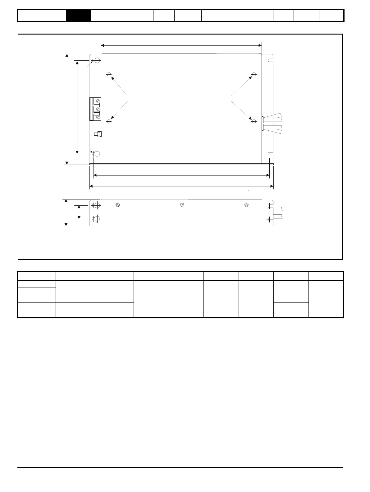
Safety
Z
ED
V: Ground stud: M6
X: M6 threaded holes for footprint mounting of the drive
Y: Footprint mounting holes 6.5mm (0.256in)
Z: Bookcase mounting slots 6.5mm (0.256in) wide
∅
Cable size:
16mm
6AWG
2
V
Y
Y
CW
A
B
H
ZZX
X
Information
Product
Information
Mechanical
Installation
Electrical
Installation
Figure 3-55 Size 3 external EMC filter
Getting
Star ted
Basic
parameters
Running
the motor
Optimization
SMARTCARD
operation
PC tools
Advanced
parameters
Technical
Data
Diagnostics
UL Listing
Information
CT part no. Manufacturer A B C D E H W
4200-6305
4200-6307
4200-6309
4200-6306
4200-6308
Schaffner
Epcos
361 mm
(14.213 in)
365 mm
(14.370 in)
396 mm
(15.591 in)
210 mm
(8.268 in)
60 mm
(2.362 in)
30 mm
(1.181 in)
414 mm
(16.299 in)
425 mm
(16.732 in)
250 mm
(9.843 in)
56 Affinity User Guide
www.controltechniques.com Issue Number: 5
Page 57

Safety
F
A
H
C
W
V
Schaffner
Epcos
Z
Z
D
B
E
V: Ground stud: M10
Z: Bookcase mounting slots 6.5mm (0.256in wide)
Information
Product
Information
Mechanical
Installation
Electrical
Installation
Getting
Star ted
Figure 3-56 Size 4 and 5 external EMC filter
Basic
parameters
Running
the motor
Optimization
SMARTCARD
operation
PC tools
Advanced
parameters
Technical
Data
Diagnostics
UL Listing
Information
CT part no. Manufacturer A B C D E F H W
4200-6406
4200-6408
4200-6503
4200-6504
4200-6405
4200-6407
4200-6501
4200-6502
Schaffner
Epcos
260 mm
(10.236 in)
275 mm
(10.827 in)
170 mm
(6.693 in)
150 mm
(5.906 in)
170 mm
(6.693 in)
100 mm
(3.937 in)
120 mm
(4.724 in)
100 mm
(3.937 in)
90 mm
(3.543in)
120 mm
(4.724 in)
65 mm
(2.559 in)
85 mm
(3.346 in)
65 mm
(2.559 in)
65 mm
(2.559 in)
85 mm
(3.346 in)
1.5 mm
(0.059in)
300 mm
(11.811 in)
2 mm
(0.079 in)
1 mm
(0.039 in)
225 mm
(8.858 in)
208 mm
(8.189 in)
249 mm
(9.803 in)
225 mm
(8.858 in)
207 mm
(8.150 in)
205 mm
(8.071 in)
249 mm
(9.803 in)
Affinity User Guide 57
Issue Number: 5 www.controltechniques.com
Page 58

Safety
V
A
GI
B
C
W
E
J
J
F
D
Z
ZZ
ZZ
V
Z
Z
Z
V: Ground stud: M10
Z: Hole size: 10.5mm
H
Information
Product
Information
Mechanical
Installation
Electrical
Installation
Figure 3-57 Size 6 external EMC filter
Getting
Star ted
Basic
parameters
Running
the motor
Optimization
SMARTCARD
operation
PC tools
Advanced
parameters
Technical
Data
Diagnostics
UL Listing
Information
CT part no.
4200-6603
4200-6604
4200-6601
4200-6602
Manufacturer
Schaffner
Epcos
ABCDE FGH I JW
191 mm
(7.717 in)
200 mm
(7.874 in)
140 mm
(5.512 in)
110 mm
(4.331 in)
108 mm
(4.252 in)
136 mm
(5.354 in)
147 mm
(5.787 in)
210 mm
(8.268 in)
2 mm
(0.079in)
38 mm
(1.496 in)
36.5 mm
(1.437 in)
295 mm
(11.614 in)
357 mm
(14.055 in)
364 mm
(14.331 in)
66 mm
(2.958 in)
128 mm
(5.039 in)
127 mm
(5.000 in)
53.5 mm
(2.106 in)
230 mm
(9.055 in)
58 Affinity User Guide
www.controltechniques.com Issue Number: 5
Page 59

Safety
A
B
C
D
H
W
V
X
X
Y
Y
Y
Z
Z
Z
V: Ground stud - M5
X: M6 threaded holes for footprint mounting of the drive
Y: Footprint mounting holes
∅
6.5mm (0.256in)
Z: Bookcase mounting slots 6.5mm (0.256in) wide
Information
Product
Information
Mechanical
Installation
Electrical
Installation
Figure 3-58 Size 1 IP54 external EMC filter
Getting
Star ted
Basic
parameters
Running
the motor
Optimization
SMARTCARD
operation
PC tools
Advanced
parameters
Technical
Data
Diagnostics
UL Listing
Information
CT part no.ManufacturerABCDHW
440 mm
(17.323 in)
450 mm
(17.717 in)
100 mm
(3.937 in)
4200-6125
4200-6124
Schaffner
390 mm
(15.354 in)
423 mm
(16.654 in)
74 mm
(2.913 in)
45 mm
(1.772 in)
Affinity User Guide 59
Issue Number: 5 www.controltechniques.com
Page 60
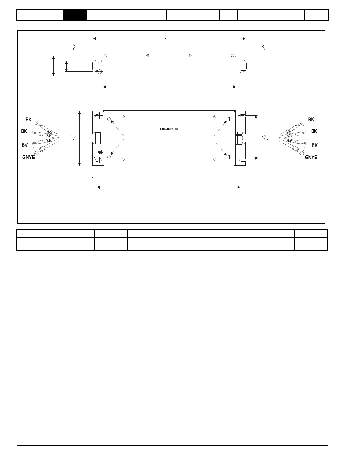
Safety
HAB
C
D
E
W
X
X
Y
Y
V
Y
Z
Z
Z
Cable size:
4mm 10 AWG
2
V: Ground stud - M5
X: M6 threaded holes for footprint mounting of the drive
Y: Footprint mounting holes
∅
6.5mm (0.256in)
Z: Bookcase mounting slots 6.5mm (0.256in) wide
Information
Product
Information
Mechanical
Installation
Electrical
Installation
Figure 3-59 Size 2 IP54 external EMC filter
Getting
Star ted
Basic
parameters
Running
the motor
Optimization
SMARTCARD
operation
PC tools
Advanced
parameters
Technical
Data
Diagnostics
UL Listing
Information
CT part no. Manufacturer A B C D E H W
4200-6218 Schaffner
371.5 mm
(14.626 in)
403.5 mm
(15.925 in)
125 mm
(4.921 in)
55 mm
(2.165 in)
30 mm
(1.181 in)
428.5 mm
(16.870 in)
156 mm
(6.102 in)
60 Affinity User Guide
www.controltechniques.com Issue Number: 5
Page 61
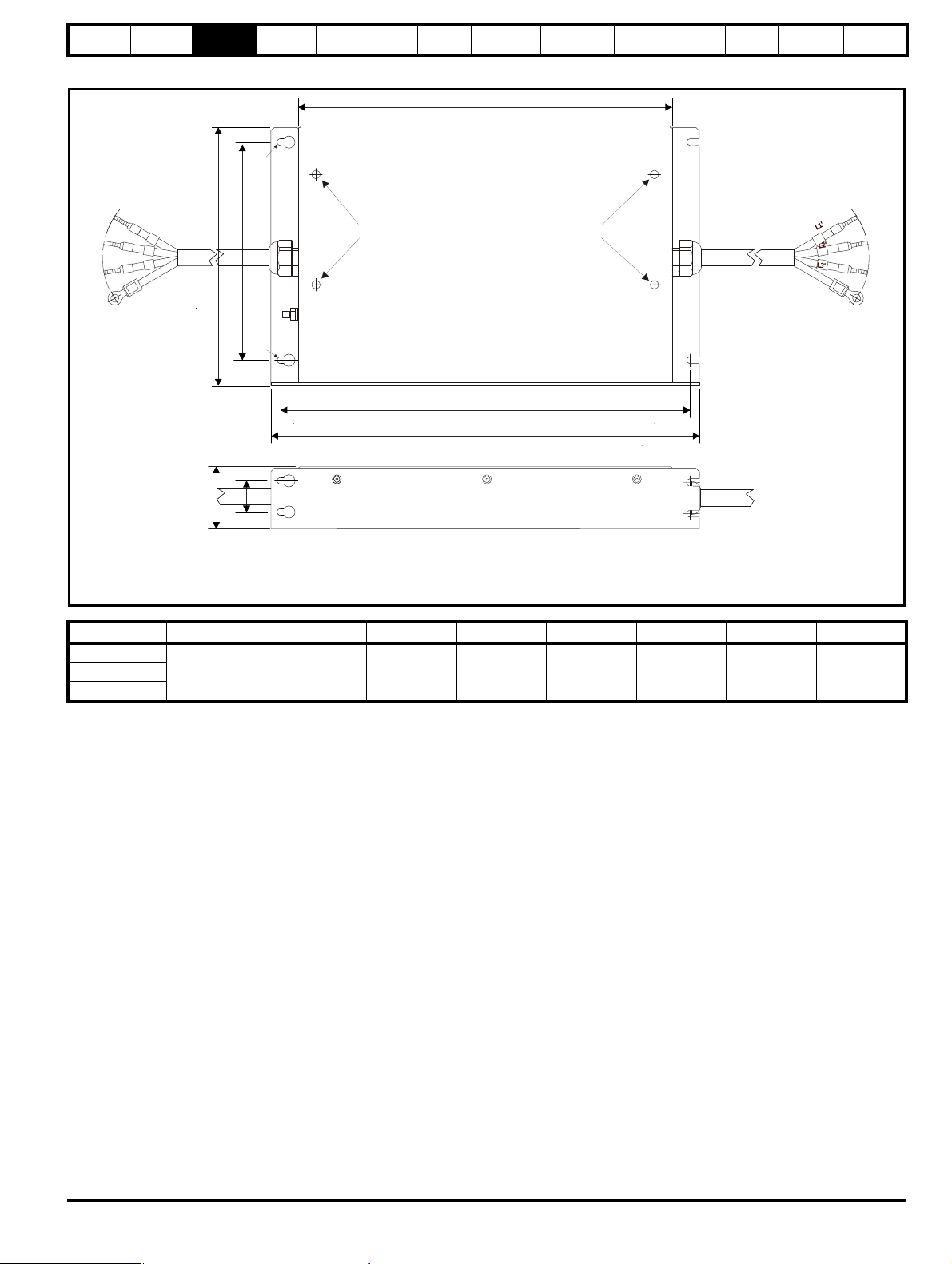
Safety
Z
ED
V: Ground stud: M6
X: M6 threaded holes for footprint mounting of the drive
Y: Footprint mounting holes 6.5mm (0.256in)
Z: Bookcase mounting slots 6.5mm (0.256in) wide
∅
V
Y
Y
C
W
A
B
H
ZZXXCable size:
16mm
6AWG
2
BKBKBK
GN/YE
Cable size:
16mm
6AWG
2
BK
BK
BK
GN/YE
Information
Product
Information
Mechanical
Installation
Electrical
Installation
Figure 3-60 Size 3 IP54 external EMC filter
Getting
Star ted
Basic
parameters
Running
the motor
Optimization
SMARTCARD
operation
PC tools
Advanced
parameters
Technical
Data
Diagnostics
UL Listing
Information
CT part no. Manufacturer A B C D E H W
4200-6319
4200-6318
4200-6320
Schaffner
361 mm
(14.213 in)
395 mm
(15.591 in)
210 mm
(8.268 in)
60 mm
(2.362 in)
30 mm
(1.181 in)
414 mm
(16.299 in)
(9.843 in)
250 mm
Affinity User Guide 61
Issue Number: 5 www.controltechniques.com
Page 62

Safety
WARNING
Information
Product
Information
Mechanical
Installation
Electrical
Installation
Getting
Star ted
Basic
parameters
Running
the motor
3.10 Electrical terminals
3.10.1 Terminal sizes and torque settings
To avoid a fire hazard and maintain validity of the UL listing,
adhere to the specified tightening torques for the power and
ground terminals. Refer to the following tables.
Table 3-10 Drive control and relay terminal data
Model Connection type Torque setting
All Plug-in terminal block 0.5 N m (0.4 lb ft)
Table 3-11 Wall mounted drive power terminal data
High current DC
and braking
Ter m.
Terminal
block (M4
screws)
Terminal
block (M5
screws)
Terminal
block (M6
screws)
M10 stud
M10 stud
M10 stud
Max
torque
1.5 N m
(1.1 lb ft)
1.5 N m
(1.1 lb ft)
2.5 N m
(1.8 lb ft)
15 N m
(11.1 lb ft)
15 N m
(11.1 lb ft)
15 N m
(11.1 lb ft)
Model
size
Ter m.
Plug-in
1
terminal
Plug-in
2
terminal
Terminal
3
block (M6
screws)
4 M10 stud
5 M10 stud
6 M10 stud
AC terminals
torque
1.5 N m
block
(1.1 lb ft)
1.5 N m
block
(1.1 lb ft)
2.5 N m
(1.8 lb ft)
15 N m
(11.1 lb ft)
15 N m
(11.1 lb ft)
15 N m
(11.1 lb ft)
Max
Table 3-12 Plug-in terminal block maximum cable sizes
Model size Terminal block description Max cable size
All 11 way control connectors
All 2 way relay connector
1 and 2 6 way AC power connector
4, 5 and 6 Low Voltage DC Enable connector
6 Heatsink fan supply connector
All BAN connector
Ground terminal
Ter m.
M5 stud
M5 stud
M6 bolt
M10 stud
M10 stud
M10 stud
1.5 mm
2.5 mm
8 mm
1.5 mm
1.5 mm
1.5 mm
(1.9 lb ft)
(1.9 lb ft)
(1.9 lb ft)
12.0 N m
(8.8 lb ft)
12.0 N m
(8.8 lb ft)
12.0 N m
(8.8 lb ft)
2
(16 AWG)
2
(12 AWG)
2
(8 AWG)
2
(16 AWG)
2
(16 AWG)
2
(16 AWG)
torque
4.0 N m
4.0 N m
4.0 N m
Max
Optimization
SMARTCARD
operation
PC tools
Advanced
parameters
Technical
Data
Diagnostics
UL Listing
Information
Table 3-13 Schaffner external EMC filter terminal data (size 1 to 6)
CT part
number
4200-6118
4200-6119
4200-6210
4200-6305
4200-6307
4200-6309
4200-6406
4200-6408
4200-6503
4200-6504
4200-6603
4200-6604
Power
connections
Max cable
size
2
4mm
12AWG
2
10mm
8AWG
2
16mm
6AWG
2
50mm
0AWG
2
25mm
4AWG
2
95mm
4/0AWG
2
50mm
0AWG
Max torque
0.8 N m
(0.6 lb ft)
2 N m
(1.5 lb ft)
2.2 N m
(1.6 lb ft)
8 N m
(5.9 lb ft)
2.3 N m
(1.7 lb ft)
20 N m
(14.7 lb ft)
8 N m
(5.9 lb ft)
connections
Ground
stud size
M5
M5
M6
M10
M6
M10
M10
M10
Ground
Max torque
3.5 N m
(2.6 lb ft)
3.5 N m
(2.6 lb ft)
3.9 N m
(2.9 lb ft)
25 N m
(18.4 lb ft)
3.9 N m
(2.9 lb ft)
25 N m
(18.4 lb ft)
25 N m
(18.4 lb ft)
25 N m
(18.4 lb ft)
Table 3-14 Epcos external EMC Filter terminal data
CT part
number
4200-6120
4200-6121
4200-6211
4200-6306
4200-6308
4200-6405
4200-6407
4200-6501
4200-6502
Power
connections
Max cable
size
2
4mm
12AWG
2
10mm
8AWG
2
16mm
6AWG
2
10mm
8AWG
2
50mm
0AWG
2
95mm
4/0AWG
Max torque
0.6 N m
(0.4 lb ft)
1.35 N m
(1.0 lb ft)
2.2 N m
(1.6 lb ft)
1.35 N m
(1.0 lb ft)
6.8 N m
(5.0 lb ft)
20 N m
(14.7 lb ft)
connections
Ground
stud size
M5
M5
M6
M10
Ground
Max torque
3.0 N m
(2.2 lb ft)
3.0 N m
(2.2 lb ft)
5.1 N m
(3.8 lb ft)
10 N m
(7.4 lb ft)
4200-6601
4200-6602
62 Affinity User Guide
www.controltechniques.com Issue Number: 5
Page 63

Safety
Information
Product
Information
Mechanical
Installation
Electrical
Installation
Getting
Star ted
Basic
parameters
Running
the motor
3.11 Routine maintenance
The standard drive should be installed in a cool, clean, well ventilated
location. Contact of moisture and dust with the drive should be
prevented.
The E12/E54 drive is protected from airborne dust and splashing water.
The E12/E66 drive is protected from any dust ingress and deckwater.
Regular checks of the following should be carried out to ensure drive /
installation reliability are maximized:
Environment
Ambient temperature
Dust
Moisture
Enclosure
Enclosure door
filters
E12/E54 drive cover
filters (size 4 to 6
only)
E12/E54 drive cover
E12/E66 drive cover
Electrical
Screw connections Ensure all screw terminals remain tight.
Crimp terminals
Cables Check all cables for signs of damage.
Ensure the standard enclosure temperature
remains at or below maximum specified.
Ensure the standard drive remains dust free –
check that the heatsink and drive fan are not
gathering dust. The lifetime of the fan is
reduced in dusty environments.
Ensure the drive enclosure shows no signs of
condensation.
Ensure filters are not blocked and that air is free
to flow.
Replace filters regularly, at least every 3
months. In some environments a filter change
may be required more frequently.
Ensure that all seals are correctly located and
not damaged.
Ensure that all seals are correctly located and
not damaged.
Ensure all crimp terminals remains tight –
check for any discoloration which could indicate
overheating.
Optimization
SMARTCARD
operation
PC tools
Advanced
parameters
Technical
Data
Diagnostics
UL Listing
Information
Affinity User Guide 63
Issue Number: 5 www.controltechniques.com
Page 64

Safety
1 2
3
Information
Product
Information
Mechanical
Installation
Electrical
Installation
Getting
Star ted
Basic
parameters
Running
the motor
Optimization
SMARTCARD
operation
PC tools
Advanced
parameters
Technical
Data
Diagnostics
3.11.1 E12/E54 filter change
There are two types of filter for the E12/E54 drives:
Small: 5610-0000
Large: 5610-0001
In order to replace the filters, follow the following instructions:
Figure 3-61 Replacing the small filters on the size 4, 5 and 6 E12/E54 drive (top and bottom on size 4 and top only on size 5 and 6)
UL Listing
Information
Undo the three screws as shown in order to remove the covers and the filter.
Figure 3-62 Replacing the large top and bottom filters on the size 5 and 6 E12/E54 drive
1. Unwind the screw to release the filter cartridge.
2. Slide cartridge out in the direction shown.
3. Undo screw fully in order to open cartridge and replace filter.
64 Affinity User Guide
www.controltechniques.com Issue Number: 5
Page 65

Safety
1
2
3
NOTE
NOTE
Information
Product
Information
Mechanical
Installation
Electrical
Installation
Getting
Star ted
Basic
parameters
3.11.2 Real-time clock battery replacement
Figure 3-63 Replacing the real-time clock battery
Running
the motor
Optimization
SMARTCARD
operation
PC tools
Advanced
parameters
Technical
Data
Diagnostics
UL Listing
Information
1. Insert a flat head screw driver into the right slot as shown and
carefully use as a lever to unclip battery cover
2. Repeat the above process for the left slot
3. Remove and rotate the cover to expose the location of the battery
Once the battery has been replaced, click the battery cover back into
position.
Low battery voltage is indicated when Pr 17.44 = 1.
A battery replacement service is provided by Control Techniques if
required.
Affinity User Guide 65
Issue Number: 5 www.controltechniques.com
Page 66

Safety
WARNING
WARNING
WARNING
WARNING
WARNING
L1
L2
L2L1L3
UVW
Optional EMC
filter
Optional
line reactor
Fuses
L3
Mains
Supply
Motor
Optional ground
connection
Supply
Ground
PE
AC Connections
BR-DC +DC
DC Connections
Internal
EMC filter
1
Information
Product
Information
Mechanical
Installation
Electrical
Installation
Getting
Star ted
Basic
parameters
Running
the motor
Optimization
SMARTCARD
operation
PC tools
Advanced
parameters
Technical
Data
Diagnostics
UL Listing
Information
4 Electrical installation
Many cable management features have been incorporated into the
product and accessories, this chapter shows how to optimize them. Key
features include:
• Internal EMC filter
• EMC compliance with shielding / grounding accessories
• Product rating, fusing and cabling information
• Brake resistor details (selection / ratings)
Electric shock risk
The voltages present in the following locations can cause
severe electric shock and may be lethal:
• AC supply cables and connections
• DC and brake cables, and connections
• Output cables and connections
• Many internal parts of the drive, and external option units
Unless otherwise indicated, control terminals are single
insulated and must not be touched.
Isolation device
The AC supply must be disconnected from the drive using
an approved isolation device before any cover is removed
from the drive or before any servicing work is performed.
STOP function
The STOP function does not remove dangerous voltages
from the drive, the motor or any external option units.
4.1 Power connections
4.1.1 AC and DC connections
Figure 4-1 Size 1 power connections
Stored charge
The drive contains capacitors that remain charged to a
potentially lethal voltage after the AC supply has been
disconnected. If the drive has been energized, the AC
supply must be isolated at least ten minutes before work
may continue.
Normally, the capacitors are discharged by an internal
resistor. Under certain, unusual fault conditions, it is possible
that the capacitors may fail to discharge, or be prevented
from being discharged by a voltage applied to the output
terminals. If the drive has failed in a manner that causes the
display to go blank immediately, it is possible the capacitors
will not be discharged. In this case, consult Control
Techniques or their authorized distributor.
Equipment supplied by plug and socket
Special attention must be given if the drive is installed in
equipment which is connected to the AC supply by a plug
and socket. The AC supply terminals of the drive are
connected to the internal capacitors through rectifier diodes
which are not intended to give safety isolation. If the plug
terminals can be touched when the plug is disconnected
from the socket, a means of automatically isolating the plug
from the drive must be used (e.g. a latching relay).
66 Affinity User Guide
www.controltechniques.com Issue Number: 5
Page 67

Safety
2
L1 L2
L2L1 L3 U V W
Optional EMC
filter
Optional
line reactor
Fuses
L3
Mains
Supply
Motor
Optional ground
connection
Supply
Ground
PE
AC Connections
BR
Thermal
overload
protection
device
DC1 DC2
DC Connections
(High current DC and braking)
-DC +DC
DC Connections
(Low current DC)
Internal
EMC filter
DC1 =
DC2 = +
-
3
L1
L2
L2L1L3
UVW
Optional EMC
filter
Optional
line reactor
Fuses
L3
Mains
Supply
Motor
Optional ground
connection
Supply
Ground
PE
AC Connections
BR
Thermal
overload
protection
device
DC1 DC2
DC Connections
(High current DC and braking)
-DC
+DC
DC Connections
(Low current DC)
Internal
EMC filter
DC1 =
DC2 = +
-
3
Information
Figure 4-2 Size 2 power connections
Product
Information
Mechanical
Installation
Installation
Electrical
Getting
Star ted
Basic
parameters
Running
the motor
Optimization
SMARTCARD
operation
PC tools
Advanced
parameters
Figure 4-3 Size 3 power connections
Technical
Data
Diagnostics
UL Listing
Information
If the heatsink mounted resistor is used (size 1 and 2 only), an overload
protection device is not required. The resistor is designed to fail safely
under fault conditions.
See Figure 4-5 for further information on ground connections.
Affinity User Guide 67
Issue Number: 5 www.controltechniques.com
On size 2 and 3, the high current DC connections must always be used
when using a braking resistor, supplying the drive from DC (low voltage DC
or high voltage DC) or using the drive in a parallel DC bus system. The low
current DC connection is used to connect low voltage DC to the drive
internal power supply and to connect the internal EMC filter.
See Figure 4-6 for further information on ground connections.
Page 68

Safety
UVW
Motor
Optional ground
connection
+DC BR
Thermal
overload
protection
device
Output connections
Input connections
Mains
Supply
L1 L2
Optional
line reactor
Optional
EMC filter
Fuses
L3
L1 L2 L3
+DC -DC
Internal
EMC filter
PE
Supply
ground
*
*
4 5 6
Size 6 only:
Heatsink
fan supply
connections
**
WARNING
Information
Product
Information
Mechanical
Installation
Figure 4-4 Size 4, 5 and 6 power connections
Electrical
Installation
Getting
Star ted
Basic
parameters
Running
the motor
Optimization
SMARTCARD
operation
PC tools
Advanced
parameters
Technical
Data
Diagnostics
UL Listing
Information
4.1.2 Ground connections
Electrochemical corrosion of earthing terminals
Ensure that grounding terminals are protected against
corrosion i.e. as could be caused by condensation.
Size 1
On a size 1, the supply and motor ground connections are made using
the studs located either side of the drive near the plug-in power
connector. Refer to Figure 4-1 on page 66.
Size 2
On a size 2, the supply and motor ground connections are made using
the grounding bridge that locates at the bottom of the drive. See Figure
4-5 for details.
Size 3
On a size 3, the supply and motor ground connections are made using
an M6 nut and bolt that locates in the fork protruding from the heatsink
between the AC supply and motor output terminals. See Figure 4-6 for
details.
Size 4, 5 and 6
On a size 4, 5 and 6, the supply and motor ground connections are
made using an M10 bolt at the top (supply) and bottom (motor) of the
drive. See Figure 4-7 on page 69.
The supply ground and motor ground connections to the drive are
connected internally by a copper conductor with a cross-sectional area
given below:
Size 4: 19.2mm
Size 5: 60mm
Size 6: 75mm
This connection is sufficient to provide the ground (equipotential
bonding) connection for the motor circuit under the following conditions:
To standard Conditions
IEC 60204-1 &
EN 60204-1
NFPA 79
If the necessary conditions are not met, an additional ground connection
must be provided to link the motor circuit ground and the supply ground.
2
(0.03in2, or slightly bigger than 6 AWG)
2
(0.09in2, or slightly bigger than 1 AWG)
2
(0.12in2, or slightly bigger than 2/0 AWG)
Supply phase conductors having cross-sectional area
not exceeding:
Size 4: 38.4mm
Size 5: 120mm
Size 6: 150mm
2
2
2
Supply protection device rating not exceeding:
Size 4: 200A
Size 5: 600A
Size 6: 1000A
* See section 4.1.2 Ground connections .
** See section 4.5 Fan connections on page 71 for more information.
68 Affinity User Guide
www.controltechniques.com Issue Number: 5
Page 69
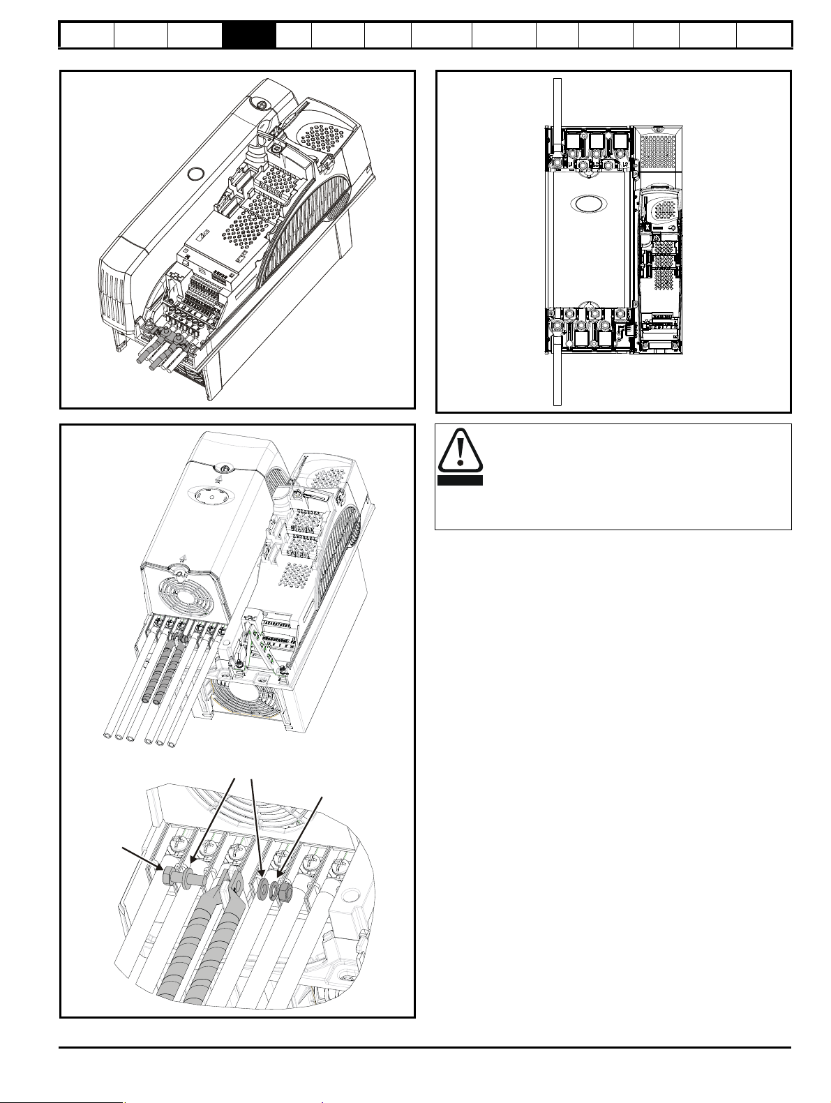
Safety
Plain washers
Spring washer
M6 bolt
Supply
ground
Motor
ground
WAR NING
Information
Product
Information
Mechanical
Installation
Electrical
Installation
Figure 4-5 Size 2 ground connections
Figure 4-6 Size 3 ground connections
Getting
Star ted
Basic
parameters
Running
the motor
Optimization
SMARTCARD
operation
PC tools
Advanced
parameters
Technical
Figure 4-7 Size 4, 5 and 6 ground connections
The ground loop impedance must conform to the
requirements of local safety regulations.
The drive must be grounded by a connection capable of
carrying the prospective fault current until the protective
device (fuse, etc.) disconnects the AC supply.
The ground connections must be inspected and tested at
appropriate intervals.
Data
Diagnostics
UL Listing
Information
4.2 AC supply requirements
Voltage:
BAx2xx 200V to 240V ±10%
BAx4xx 380V to 480V ±10%
BAx5xx 500V to 575V ±10%
BAx6xx 500V to 690V ±10%
Number of phases: 3
Maximum supply imbalance: 2% negative phase sequence (equivalent
to 3% voltage imbalance between phases).
Frequency range: 48 to 65 Hz
For UL compliance only, the maximum supply symmetrical fault current
must be limited to 100kA
4.2.1 Supply types
All drives are suitable for use on any supply type i.e TN-S, TN-C-S, TT
and IT.
• Supplies with voltage up to 600V may have grounding at any
potential, i.e. neutral, centre or corner (“grounded delta”)
• Supplies with voltage above 600V may not have corner grounding
Drives are suitable for use on supplies of installation category III and
lower, according to IEC60664-1. This means they may be connected
permanently to the supply at its origin in a building, but for outdoor
installation additional over-voltage suppression (transient voltage surge
suppression) must be provided to reduce category IV to category III.
Affinity User Guide 69
Issue Number: 5 www.controltechniques.com
Page 70

Safety
WARNING
L
Y
100
----------
V
3
-------
×
1
2π f I
------------
×=
Internal
wiring
User wiring
from a 5A
fused supply
Information
Product
Information
Mechanical
Installation
Electrical
Installation
Getting
Star ted
Basic
parameters
Running
the motor
Optimization
SMARTCARD
operation
PC tools
Advanced
parameters
Technical
Data
Diagnostics
UL Listing
Information
Operation with IT (ungrounded) supplies:
Special attention is required when using internal or external
EMC filters with ungrounded supplies, because in the event
of a ground (earth) fault in the motor circuit the drive may not
trip and the filter could be over-stressed. In this case, either
the filter must not be used (removed) or additional
independent motor ground fault protection must be provided.
Refer to Table 4-1.
For instructions on removal, refer to Figure 4-20 Removal of
internal EMC filter (size 1 to 3) and Figure 4-21 Removal of
internal EMC filter (sizes 4 to 6) on page 81.
For details of ground fault protection contact the supplier of
the drive.
A ground fault in the supply has no effect in any case. If the motor must
continue to run with a ground fault in its own circuit then an input
isolating transformer must be provided and if an EMC filter is required it
must be located in the primary circuit.
Unusual hazards can occur on ungrounded supplies with more than one
source, for example on ships. Contact the supplier of the drive for more
information.
Table 4-1 Behavior of the drive in the event of a motor circuit
ground (earth) fault with an IT supply
Drive size Internal filter only External filter (with internal)
1 and 2 Drive trips on fault Drive trips on fault
3
4 to 6
May not trip – precautions
required
May not trip – precautions
required
Drive trips on fault
May not trip – precautions
required
Reactor current ratings
The current rating of the line reactors should be as follows:
Continuous current rating:
Not less than the continuous input current rating of the drive
Repetitive peak current rating:
Not less than twice the continuous input current rating of the drive
4.2.3 Input inductor calculation
To calculate the inductance required (at Y%), use the following equation:
Where:
I = drive rated input current (A)
L = inductance (H)
f = supply frequency (Hz)
V = voltage between lines
4.3 Auxiliary power supply
The size 6 E12/54 drive requires an auxiliary 110V or 230V power supply
to feed the internal 24V power supply. The 24V power supply is used to
supply the heatsink fans on the power module.
Figure 4-8 Location of size 6 E12/54 drive 24V power supply
4.2.2 Supplies requiring line reactors
Input line reactors reduce the risk of damage to the drive resulting from
poor phase balance or severe disturbances on the supply network.
Where line reactors are to be used, reactance values of approximately
2% are recommended. Higher values may be used if necessary, but may
result in a loss of drive output (reduced torque at high speed) because of
the voltage drop.
For all drive ratings, 2% line reactors permit drives to be used with a
supply unbalance of up to 3.5% negative phase sequence (equivalent to
5% voltage imbalance between phases).
Severe disturbances may be caused by the following factors, for example:
• Power factor correction equipment connected close to the drive.
• Large DC drives having no or inadequate line reactors connected to
the supply.
• Across the line (DOL) started motor(s) connected to the supply such
that when any of these motors are started, the voltage dip exceeds
20%.
Such disturbances may cause excessive peak currents to flow in the
input power circuit of the drive. This may cause nuisance tripping, or in
extreme cases, failure of the drive.
Drives of low power rating may also be susceptible to disturbance when
connected to supplies with a high rated capacity.
Line reactors are particularly recommended for use with the following
drive models when one of the above factors exists, or when the supply
capacity exceeds 175kVA:
BA1201 BA1202 BA1203 BA1204
BA1401 BA1402 BA1403 BA1404
Model sizes BA1405 to BA4606 have an internal DC choke and BA5201
to BA6602 have internal AC line chokes, so they do not require AC line
reactors except for cases of excessive phase unbalance or extreme
supply conditions.
When required, each drive must have its own reactor(s). Three individual
reactors or a single three-phase reactor should be used.
CT part number: 8510-0000
Current rating: 10A
Input voltage: 85 to 123 / 176 to 264Vac auto switching
Cable size: 0.5mm
2
(20AWG)
Supply fuse: 5A slow-blow
70 Affinity User Guide
www.controltechniques.com Issue Number: 5
Page 71
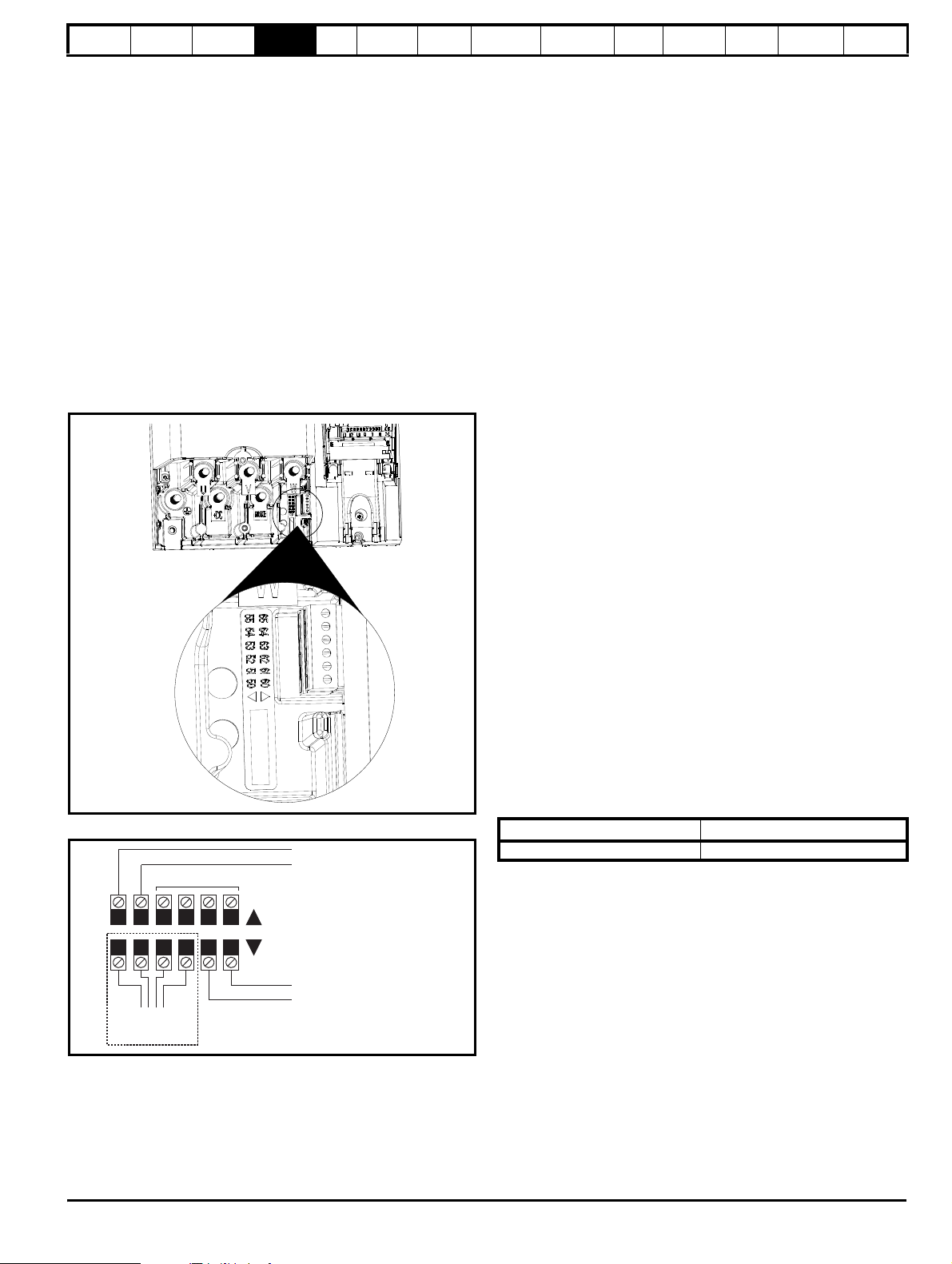
Safety
55 54 53 52 51 50
65 64 63 62 61 60
To the heatsink fan
Pre-wired internally
0V
24V low voltage DC mode enable
Not used
0V
24V heatsink fan supply
Upper terminal connector
Lower terminal connector
Information
Product
Information
Mechanical
Installation
Electrical
Installation
Getting
Star ted
Basic
parameters
Running
the motor
Optimization
SMARTCARD
operation
PC tools
Advanced
parameters
Technical
Data
Diagnostics
UL Listing
Information
4.4 Supplying the drive with DC / DC bus
paralleling
The connecting of the DC bus between several drives is typically used to:
1. Return energy from a drive which is being overhauled by the load to
a second motoring drive.
2. Allow the use of one braking resistor to dissipate regenerative
energy from several drives.
There are limitations to the combinations of drives which can be used in
this configuration.
For application data, contact the supplier of the drive.
4.5 Fan connections
4.5.1 Heatsink fan supply
The heatsink fan on size 1 to 5 is supplied internally by the drive. The
heatsink fan on size 6 requires an external 24Vdc supply. The
connections for the heatsink fan supply must be made to the upper
terminal connector near to the W phase output on the drive. Figure 4-9
shows the position of the heatsink fan supply connections.
Figure 4-9 Location of the size 6 heatsink fan supply connections
Figure 4-10 Size 6 heatsink fan supply connections
4.6 Control 24Vdc supply
The 24Vdc input has three main functions.
• It can be used to supplement the drive’s own internal 24V when
multiple SM-I/O Plus modules are being used and the current drawn
by these modules is greater than the drive can supply. (If too much
current is drawn from the drive, the drive will initiate a 'PS.24V' trip)
• It can be used as a back-up power supply to keep the control circuits
of the drive powered up when the line power supply is removed. This
allows any fieldbus modules or serial communications to continue to
operate.
• It can be used to commission the drive when the line power supply is
not available, as the display operates correctly. However, the drive
will be in the UV trip state unless either line power supply or low
voltage DC operation is enabled, therefore diagnostics may not be
possible. (Power down save parameters are not saved when using
the 24V back-up power supply input.)
The working voltage range of the 24V power supply is as follows:
Maximum continuous operating voltage: 30.0 V
Minimum continuous operating voltage: 19.2 V
Nominal operating voltage: 24.0 V
Minimum start up voltage: 21.6 V
Maximum power supply requirement at 24V: 60 W
Recommended fuse: 3 A, 50 Vdc
Minimum and maximum voltage values include ripple and noise. Ripple
and noise values must not exceed 5%.
4.7 Ratings
The input current is affected by the supply voltage and impedance.
Typical input current
The values of typical input current are given to aid calculations for power
flow and power loss.
The values of typical input current are stated for a balanced supply.
Maximum continuous input current
The values of maximum continuous input current are given to aid the
selection of cables and fuses. These values are stated for the worst case
condition with the unusual combination of stiff supply with bad balance.
The value stated for the maximum continuous input current would only
be seen in one of the input phases. The current in the other two phases
would be significantly lower.
The values of maximum input current are stated for a supply with a 2%
negative phase-sequence imbalance and rated at the supply fault
current given in Table 4-2.
Table 4-2 Supply fault current used to calculate maximum input currents
Model Symmetrical fault level (kA)
All 100
The heatsink fan supply requirements are as follows:
Nominal voltage: 24Vdc
Minimum voltage: 23.5Vdc
Maximum voltage: 27Vdc
Current drawn: 3.3A
Recommended power supply: 24V, 100W, 4.5A
Recommended fuse: 4A fast blow (I
Affinity User Guide 71
Issue Number: 5 www.controltechniques.com
2
t less than 20A2s)
Page 72
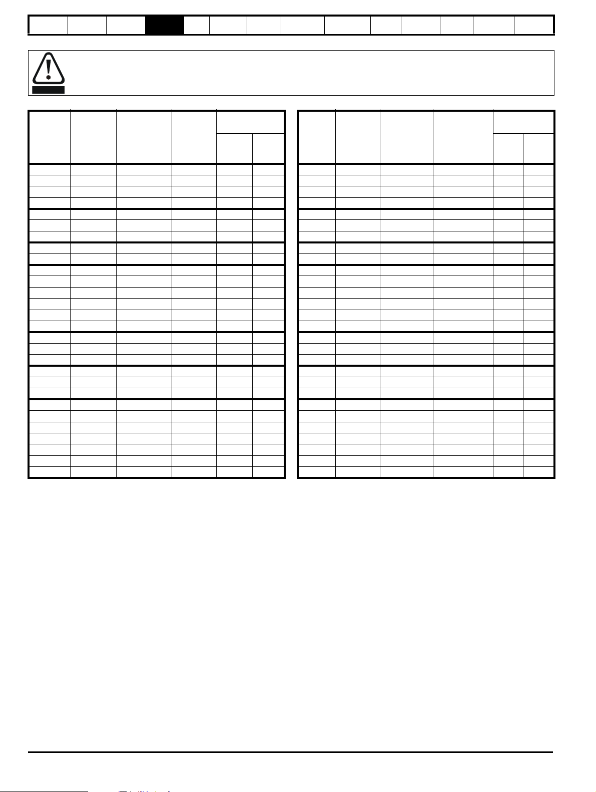
Safety
WARNING
Information
Product
Information
Mechanical
Installation
Electrical
Installation
Getting
Star ted
Basic
parameters
Running
the motor
Optimization
SMARTCARD
operation
PC tools
Advanced
parameters
Technical
Data
Diagnostics
Fuses
The AC supply to the drive must be installed with suitable protection against overload and short-circuits. Table 4-3, Table 4-4 and
Table 4-5 show recommended fuse ratings. Failure to observe this requirement will cause risk of fire.
UL Listing
Information
Table 4-3 Size 1 to 3 input current, fuse and cable size ratings (European)
Model
Typical
input
current
A
Maximum
continuous
input current
A
Fuse
rating
IEC gG
A
Cable size
EN60204
Input
2
mm
Output
2
mm
BA1201 7.1 9.5 10 1.5 1.0
BA1202 9.2 11.3 12 1.5 1.0
BA1203 12.5 16.4 20 4.0 1.0
BA1204 15.4 19.1 20 4.0 1.5
BA2201 13.4 18.1 20 4.0 2.5
BA2202 18.2 22.6 25 4.0 4.0
BA2203 24.2 28.3 32 6.0 6.0
BA3201 35.4 43.1 50 16 16
BA3202 46.8 54.3 63 25 25
BA1401 4.1 4.8 8 1.0 1.0
BA1402 5.1 5.8 8 1.0 1.0
BA1403 6.8 7.4 8 1.0 1.0
BA1404 9.3 10.6 12 1.5 1.0
BA1405 10 11 12 1.5 1.0
BA1406 12.6 13.4 16 2.5 1.5
BA2401 15.7 17 20 4.0 2.5
BA2402 20.2 21.4 25 4.0 4.0
BA2403 26.6 27.6 32 6.0 6.0
BA3401 34.2 36.2 40 10 10
BA3402 40.2 42.7 50 16 16
BA3403 51.3 53.5 63 25 25
BA3501 5.0 6.7 8 1.0 1.0
BA3502 6.0 8.2 10 1.0 1.0
BA3503 7.8 11.1 12 1.5 1.0
BA3504 9.9 14.4 16 2.5 1.5
BA3505 13.8 18.1 20 4.0 2.5
BA3506 18.2 22.2 25 4.0 4.0
BA3507 22.2 26.0 32 6.0 6.0
Table 4-4 Size 1 to 3 input current, fuse and cable size ratings (USA)
Model
Typical
input
current
A
Maximum
continuous
input current
A
Fuse rating
Class CC or
J <30A
Class J >30A
A
Cable size
UL508C
Input
Output
AWG
AWG
BA1201 7.1 9.5 10 14 18
BA1202 9.2 11.3 15 14 16
BA1203 12.5 16.4 20 12 14
BA1204 15.4 19.1 20 12 14
BA2201 13.4 18.1 20 12 14
BA2202 18.2 22.6 25 10 10
BA2203 24.2 28.3 30 8 8
BA3201 35.4 43.1 45 6 6
BA3202 46.8 54.3 60 4 4
BA1401 4.1 4.8 8 16 22
BA1402 5.1 5.8 8 16 20
BA1403 6.8 7.4 10 16 18
BA1404 9.3 10.6 15 14 16
BA1405 10 11 15 14 14
BA1406 12.6 13.4 15 14 14
BA2401 15.7 17 20 12 14
BA2402 20.2 21.4 25 10 10
BA2403 26.6 27.6 30 8 8
BA3401 34.2 36.2 40 6 6
BA3402 40.2 42.7 45 6 6
BA3403 51.3 53.5 60 4 4
BA3501 5.0 6.7 10 16 18
BA3502 6.0 8.2 10 16 16
BA3503 7.8 11.1 15 14 14
BA3504 9.9 14.4 15 14 14
BA3505 13.8 18.1 20 12 14
BA3506 18.2 22.2 25 10 10
BA3507 22.2 26.0 30 8 8
72 Affinity User Guide
www.controltechniques.com Issue Number: 5
Page 73

Safety
NOTE
NOTE
NOTE
Information
Product
Information
Mechanical
Installation
Electrical
Installation
Getting
Star ted
Basic
parameters
Running
the motor
Table 4-5 Size 4 and larger input current, fuse and cable size ratings
Fuse option 1
Typical input
current
Model
Maximum
input current
IEC class
gR
North
America:
Ferraz HSJ
AAAAA A
BA
4201 62.1
4202 72.1
BA
4203 94.5
BA
5201 116
BA
5202 137
BA
4401 61.2
BA
4402 76.3
BA
4403 94.1
BA
5401 126
BA
5402 152
BA
6401 224
BA
6402 247
BA
4601 23
BA
4602 26.1
BA
4603 32.9
BA
4604 39
BA
4605 46.2
BA
4606 55.2
BA
5601 75.5
BA
5602 89.1
BA
6601 128
BA
6602 144
BA
68.9 100 90 90 160 25 25 3 3
78.1 100 100 100 160 35 35 3 3
99.9 125 125 125 200 70 70 1 1
142 200 175 160 200 95 95 2/0 2/0
165 250 225 200 250 120 120 4/0 4/0
62.3 80 80 80 160 25 25 3 3
79.6 110 110 100 200 35 35 2 2
97.2 125 125 125 200 70 70 1 1
131 200 175 160 200 95 95 2/0 2/0
156 250 225 200 250 120 120 4/0 4/0
241 315 300 250 315 2 x 70 2 x 70 2 x 2/0 2 x 2/0
266 315 300 300 350 2 x 95 2 x 95 2 x 4/0 2 x 4/0
26.5 63 60 32 125 4 4 10 10
28.8 63 60 40 125 6 6 8 8
35.1 63 60 50 125 10 10 8 8
41 63 60 50 125 16 16 6 6
47.9 63 60 63 125 16 16 6 6
56.9 80 60 63 125 25 25 4 4
82.6 125 100 90 160 35 35 2 2
94.8 125 100 125 160 50 50 1 1
138 200 200 200 200 2 x 50 2 x 50 2 x 1 2 x 1
156 200 200 200 200 2 x 50 2 x 50 2 x 1 2 x 1
Optimization
SMARTCARD
operation
PC tools
Fuse option 2
semiconductor fuse in series
with HRC fuse or breaker
HRC
IEC class gG
UL class J
Semi-
conductor
IEC class aR
Advanced
parameters
Technical
Data
Diagnostics
Cable size
EN60204 UL508C
Input
mm
Output
2
mm
Input
2
AWG
UL Listing
Information
Output
AWG
Installation class (ref: IEC60364-5-52:2001)
B1 - Separate cables in conduit.
B2 - Multicore cable in conduit
C - Multicore cable in free air.
Cable sizes are from IEC60364-5-52:2001 table A.52.C with correction
factor for 40°C ambient of 0.87 (from table A52.14) for cable installation
method B2 (multicore cable in conduit).
Only PVC insulated cables should be used.
Cable size may be reduced if a different installation method is used, or if
the ambient temperature is lower.
The recommended cable sizes above are only a guide. The mounting
and grouping of cables affects their current-carrying capacity, in some
cases smaller cables may be acceptable but in other cases a larger
cable is required to avoid excessive temperature or voltage drop. Refer
to local wiring regulations for the correct size of cables.
N
The recommended output cable sizes assume that the motor maximum
current matches that of the drive. Where a motor of reduced rating is
used the cable rating may be chosen to match that of the motor. To
ensure that the motor and cable are protected against overload, the
drive must be programmed with the correct motor rated current.
N
UL listing is dependent on the use of the correct type of UL-listed fuse,
and applies when symmetrical short-circuit current does not exceed
100kA. See Chapter 14 UL listing information on page 264 for sizing
information.
A fuse or other protection must be included in all live connections to the
AC supply.
An MCB (miniature circuit breaker) or MCCB (moulded-case circuitbreaker) with type C may be used in place of fuses on sizes 1 to 3 under
the following conditions:
• The fault-clearing capacity must be sufficient for the installation
• For frame sizes 2 and 3, the drive must be mounted in an enclosure
which meets the requirements for a fire enclosure (For details
regarding fire enclosures see section 3.2.6 Fire protection on
page 20).
See Chapter 14 UL listing information on page 264 for UL listing
requirements.
Fuse types
The fuse voltage rating must be suitable for the drive supply voltage.
Ground connections
The drive must be connected to the system ground of the AC supply.
The ground wiring must conform to local regulations and codes of
practice.
4.7.1 Main AC supply contactor
The recommended AC supply contactor type for sizes 1 to 6 is AC1.
Affinity User Guide 73
Issue Number: 5 www.controltechniques.com
Page 74

Safety
WARNING
Information
Product
Information
Mechanical
Installation
Electrical
Installation
Getting
Star ted
Basic
parameters
Running
the motor
Optimization
SMARTCARD
operation
PC tools
Advanced
parameters
Technical
Data
Diagnostics
UL Listing
Information
4.8 Output circuit and motor protection
The output circuit has fast-acting electronic short-circuit protection which
limits the fault current to typically no more than five times the rated
output current, and interrupts the current in approximately 20µs. No
additional short-circuit protection devices are required.
The drive provides overload protection for the motor and its cable. For
this to be effective, Pr 0.46 Motor rated current must be set to suit the
motor.
Pr 0.46 Motor rated current must be set correctly to avoid a
risk of fire in the event of motor overload.
There is also provision for the use of a motor thermistor to prevent overheating of the motor, e.g. due to loss of cooling.
4.8.1 Cable types and lengths
Since capacitance in the motor cable causes loading on the output of the
drive, ensure the cable length does not exceed the values given in Table
4-6, Table 4-7 and Table 4-8.
Use 105°C (221°F) (UL 60/75°C temp rise) PVC-insulated cable with
copper conductors having a suitable voltage rating, for the following
power connections:
• AC supply to external EMC filter (when used)
• AC supply (or external EMC filter) to drive
• Drive to motor
• Drive to braking resistor
Table 4-6 Maximum motor cable lengths (200V drives)
200V Nominal AC supply voltage
Maximum permissible motor cable length for each of
Model
3kHz 4kHz 6kHz 8kHz 12kHz 16kHz
BA1201 65m (210ft)
BA1202 100m (330ft)
BA1203 130m (425ft)
BA1204
BA2201
BA2202
BA2203
200m
(660ft)
BA3201
BA3202
BA4201
BA4202
BA4203
BA5201
BA5202
250m
(820ft)
250m
(820ft)
the following frequencies
150m
(490ft)
185m
(607ft)
185m
(607ft)
100m
(330ft)
125m
(410ft)
125m
(410ft)
(245ft)
(295ft)
(295ft)
75m
90m
90m
5 0 m
(165ft)
37m
(120ft)
Table 4-7 Maximum motor cable lengths (400V drives)
400V Nominal AC supply voltage
Maximum permissible motor cable length for each of
Model
the following frequencies
3kHz 4kHz 6kHz 8kHz 12kHz 16kHz
BA1401 65m (210ft)
BA1402 100m (330ft)
BA1403 130m (425ft)
BA1404
BA1405
BA1406
BA2401
BA2402
BA2403
200m
(660ft)
150m
(490ft)
100m
(330ft)
75m
(245ft)
5 0 m
(165ft)
37m
(120ft)
BA3401
BA3402
BA3403
BA4401
BA4402
BA4403
BA5401
BA5402
250m
(820ft)
185m
(607ft)
125m
(410ft)
90m
(295ft)
BA6401
BA6402
Table 4-8 Maximum motor cable lengths (575V drives)
575V Nominal AC supply voltage
Maximum permissible motor cable length for each of
Model
the following frequencies
3kHz 4kHz 6kHz 8kHz 12kHz 16kHz
BA3501
BA3502
BA3503
BA3504
BA3505
200m
(660ft)
150m
(490ft)
100m
(330ft)
75m
(245ft)
BA3506
BA3507
Table 4-9 Maximum motor cable lengths (690V drives)
690V Nominal AC supply voltage
Maximum permissible motor cable length for each of
Model
the following frequencies
3kHz 4kHz 6kHz 8kHz 12kHz 16kHz
BA4601
BA4602
BA4603
BA4604
BA4605
BA4606
250m
(820ft)
185m
(607ft)
125m
(410ft)
90m
(295ft)
BA5601
BA5602
BA6601
BA6602
• Cable lengths in excess of the specified values may be used only
when special techniques are adopted; refer to the supplier of the
drive.
• The default switching frequency is 3kHz.
74 Affinity User Guide
www.controltechniques.com Issue Number: 5
Page 75

Safety
Normal capacitance
Shield or armour
separated from the cores
High capacitance
Shield or armour close
to the cores
Motor
protection
relay
Chain connection (preferred)
connection
Inductor
Motor
protection
relay
Information
High-capacitance cables
The maximum cable length is reduced from that shown in Table 4-6,
Table 4-7, Table 4-8 and Table 4-9 if high capacitance motor cables are
used.
Most cables have an insulating jacket between the cores and the armor
or shield; these cables have a low capacitance and are recommended.
Product
Information
Mechanical
Installation
Electrical
Installation
Getting
Star ted
Basic
parameters
Running
the motor
Optimization
SMARTCARD
operation
PC tools
Advanced
parameters
Technical
Data
Diagnostics
It is recommended that each motor is connected through a protection relay
since the drive cannot protect each motor individually. For
connection, a
sinusoidal filter or an output inductor must be connected as shown in
Figure 4-13, even when the cable lengths are less than the maximum
permissible. For details of inductor sizes refer to the supplier of the drive.
Figure 4-12 Preferred chain connection for multiple motors
Cables that do not have an insulating jacket tend to have high
capacitance; if a cable of this type is used, the maximum cable length is
half that quoted in the tables. (Figure 4-11 shows how to identify the two
types.)
Figure 4-11 Cable construction influencing the capacitance
The cable used for Table 4-6, Table 4-7, Table 4-8 and Table 4-9 is
shielded and contains four cores. Typical capacitance for this type of
cable is 130pF/m (i.e. from one core to all others and the shield
connected together).
4.8.2 Motor winding voltage
The PWM output voltage can adversely affect the inter-turn insulation in
the motor. This is because of the high rate of change of voltage, in
conjunction with the impedance of the motor cable and the distributed
nature of the motor winding.
For normal operation with AC supplies up to 500Vac and a standard
motor with a good quality insulation system, there is no need for any
special precautions. In case of doubt the motor supplier should be
consulted.
Special precautions are recommended under the following conditions,
but only if the motor cable length exceeds 10m:
• AC supply voltage exceeds 500V
• DC supply voltage exceeds 670V
• Operation of 400V drive with continuous or very frequent sustained
braking
• Multiple motors connected to a single drive
For multiple motors, the precautions given in section 4.8.3 Multiple
motors should be followed.
For the other cases listed, it is recommended that an inverter-rated
motor be used. This has a reinforced insulation system intended by the
manufacturer for repetitive fast-rising pulsed voltage operation.
Users of 575V NEMA rated motors should note that the specification for
inverter-rated motors given in NEMA MG1 section 31 is sufficient for
motoring operation but not where the motor spends significant periods
braking. In that case an insulation peak voltage rating of 2.2kV is
recommended.
If it is not practical to use an inverter-rated motor, an output choke
(inductor) should be used. The recommended type is a simple iron-cored
component with a reactance of about 2%. The exact value is not critical.
This operates in conjunction with the capacitance of the motor cable to
increase the rise-time of the motor terminal voltage and prevent
excessive electrical stress.
4.8.3 Multiple motors
Open-loop only (not RFC mode)
If the drive is to control more than one motor, one of the fixed V/F modes
should be selected (Pr 5.14 = Fd or SrE). Make the motor connections
as shown in Figure 4-12 and Figure 4-13. The maximum cable lengths in
Table 4-6, Table 4-7, Table 4-8 and Table 4-9 apply to the sum of the
total cable lengths from the drive to each motor.
Affinity User Guide 75
Issue Number: 5 www.controltechniques.com
Figure 4-13 Alternative connection for multiple motors
4.8.4 / Δ motor operation
The voltage rating for A and Δ connections of the motor should always
be checked before attempting to run the motor.
The default setting of the motor rated voltage parameter is the same as
the drive rated voltage, i.e.
400V drive 400V rated voltage
200V drive 200V rated voltage
A typical 3 phase motor would be connected in
for 200V operation, however, variations on this are common e.g.
A 690V Δ 400V.
A for 400V operation or Δ
UL Listing
Information
Page 76
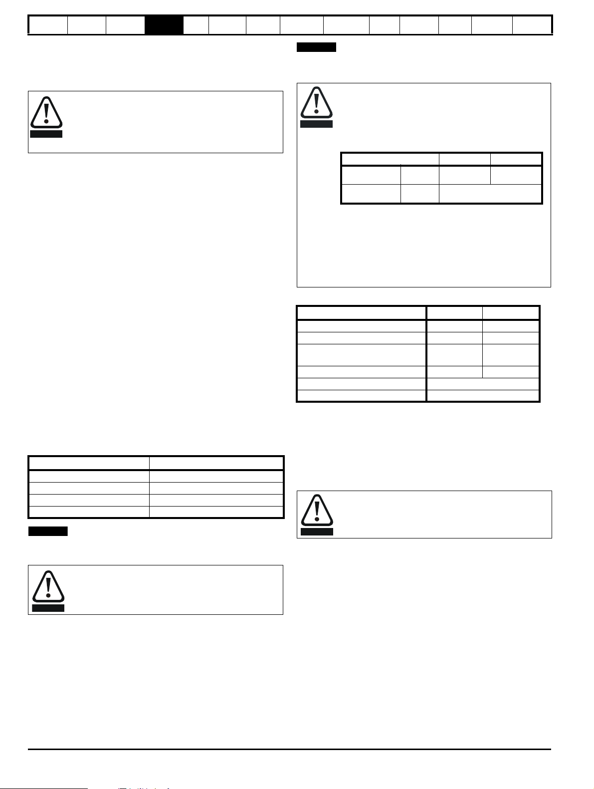
Safety
WARNING
NOTE
WARNING
NOTE
CAUTION
Parameter 200V drive 400V drive
Full power
braking time
Pr
10.30
0.09 0.02
Full power
braking period
Pr
10.31
3.3
WARNING
Information
Product
Information
Mechanical
Installation
Electrical
Installation
Getting
Star ted
Basic
parameters
Running
the motor
Incorrect connection of the windings will cause severe under or over
fluxing of the motor, leading to a very poor output torque or motor
saturation and overheating respectively.
4.8.5 Output contactor
If the cable between the drive and the motor is to be
interrupted by a contactor or circuit breaker, ensure that the
drive is disabled before the contactor or circuit breaker is
opened or closed. Severe arcing may occur if this circuit is
interrupted with the motor running at high current and low
speed.
A contactor is sometimes required to be installed between the drive and
motor for safety purposes.
The recommended motor contactor is the AC3 type.
Switching of an output contactor should only occur when the output of
the drive is disabled.
Opening or closing of the contactor with the drive enabled will lead to:
1. OI.AC trips (which cannot be reset for 10 seconds)
2. High levels of radio frequency noise emission
3. Increased contactor wear and tear
4.9 Braking
Braking occurs when the drive is decelerating the motor, or is preventing
the motor from gaining speed due to mechanical influences. During
braking, energy is returned to the drive from the motor.
When the motor is being braked by the drive, the maximum regenerated
power that the drive can absorb is equal to the power dissipation
(losses) of the drive.
When the regenerated power is likely to exceed these losses, the DC
bus voltage of the drive increases. Under default conditions, the drive
brakes the motor under PI control, which extends the deceleration time
as necessary in order to prevent the DC bus voltage from rising above a
user defined set-point.
If the drive is expected to rapidly decelerate a load, or to hold back an
overhauling load, a braking resistor must be installed.
Table 4-10 shows the DC voltage level at which the drive turns on the
braking transistor.
Table 4-10 Braking transistor turn on voltage
Drive voltage rating DC bus voltage level
200V 390V
400V 780V
575V 930V
690V 1120V
N
When a braking resistor is used, Pr 0.15 should be set to FASt ramp
mode.
High temperatures
Braking resistors can reach high temperatures. Locate
braking resistors so that damage cannot result. Use cable
having insulation capable of withstanding high temperatures.
4.9.1 Heatsink mounted braking resistor
A resistor has been especially designed to be mounted within the
heatsink of the drive (sizes 1 and 2). See the Installation Sheet provided
with the heatsink mounted braking resistor. The design of the resistor is
such that no thermal protection circuit is required, as the device will fail
safely under fault conditions. On sizes 1 and 2, the in built software
overload protection is set up at default for the designated heatsink
mounted resistor. Table 4-11 provides the resistor data for each drive
rating.
Optimization
SMARTCARD
operation
PC tools
Advanced
parameters
Technical
Data
Diagnostics
UL Listing
Information
N
The heatsink mounted resistor is suitable for applications with a low level
of regen energy only. See Table 4-11.
Braking resistor overload protection parameter
settings. Failure to observe the following
information may damage the resistor.
The drive’s software contains an overload protection
function for a braking resistor. On size 1 and 2 this function
is enabled at default to protect the heatsink mounted
resistor. Below are the parameter settings.
For more information on the braking resistor software
overload protection, see Pr 10.30 and Pr 10.31 full
descriptions in the Advanced User Guide.
If the heatsink mounted braking resistor is to be used at
more than half of its average power rating then the drive's
cooling fan must be at full speed controlled by setting
Pr 6.45 to On (1).
Table 4-11 Heatsink mounted braking resistor data
Parameter Size 1 Size 2
Part number 1220-2756-01 1220-2758-01
DC resistance at 25°C75Ω 37.5Ω
Peak instantaneous power over
1ms at nominal resistance
Average power over 60s * 50W 100W
Ingress Protection (IP) rating IP54
Maximum altitude 2000m
* To keep the temperature of the resistor below 70°C (158°F) in a 30°C
(86°F) ambient, the average power rating is 50W for size 1 and 100W for
size 2. The above parameter settings ensure this is the case.
Size 3 and larger do not have heatsink mounted braking resistors, hence
the default values of Pr 10.30 and Pr 10.31 are 0 (i.e. software braking
resistor overload protection disabled).
4.9.2 External braking resistor
Overload protection
When an external braking resistor is used, it is essential that
an overload protection device is incorporated in the braking
resistor circuit; this is described in Figure 4-14 on page 77.
When a braking resistor is to be mounted outside the enclosure, ensure
that it is mounted in a ventilated metal housing that will perform the
following functions:
• Prevent inadvertent contact with the resistor
• Allow adequate ventilation for the resistor
When compliance with EMC emission standards is required, external
connection requires the cable to be armored or shielded, since it is not
fully contained in a metal enclosure. See section 4.11.5 Compliance with
generic emission standards on page 84 for further details.
Internal connection does not require the cable to be armored or
shielded.
8kW 16kW
76 Affinity User Guide
www.controltechniques.com Issue Number: 5
Page 77

Optional
EMC
filter
Stop
Start /
Reset
Thermal
protection
device
Braking resistor
Drive
Main contactor
power supply
+DC
BR
Safety
Information
Minimum resistances and power ratings
Table 4-12 Minimum resistance values and peak power rating for
Product
Information
Mechanical
Installation
Electrical
Installation
Getting
Star ted
Basic
parameters
the motor
the braking resistor at 40°C (104°F)
Model
Minimum
resistance*
Ω
Instantaneous
power rating
kW
BA1201
BA1202 2.2
43 3.5
Average power
for 60s
kW
1.5
BA1203 3.0
BA1204 29 5.3 4.4
BA2201
BA2202 8.0
18 8.9
6.0
BA2203 8.9
BA3201
BA3202 19.3
5.0 30.3
BA4201**
BA4202** 27.8
5.0 30.3
13.1
22.5
BA4203** 30.3
BA5201
BA5202
BA1401
BA1402 2.2
BA1403 3.0
3.5 53 43.5
1.5
74 8.3
BA1404 4.4
BA1405
BA1406 8.0
58 10.6
BA2401
BA2402 13.1
19 33.1
6.0
9.6
Running
Optimization
SMARTCARD
operation
PC tools
Advanced
parameters
Technical
Data
Diagnostics
Information
For high-inertia loads or under continuous braking, the continuous power
dissipated in the braking resistor may be as high as the power rating of
the drive. The total energy dissipated in the braking resistor is dependent
on the amount of energy to be extracted from the load.
The instantaneous power rating refers to the short-term maximum power
dissipated during the on intervals of the pulse width modulated braking
control cycle. The braking resistor must be able to withstand this
dissipation for short intervals (milliseconds). Higher resistance values
require proportionately lower instantaneous power ratings.
In most applications, braking occurs only occasionally. This allows the
continuous power rating of the braking resistor to be much lower than
the power rating of the drive. It is essential, though, that the
instantaneous power rating and energy rating of the braking resistor are
sufficient for the most extreme braking duty that is likely to be
encountered.
Optimization of the braking resistor requires a careful consideration of
the braking duty.
Select a value of resistance for the braking resistor that is not less than
the specified minimum resistance. Larger resistance values may give a
cost saving, as well as a safety benefit in the event of a fault in the
braking system. Braking capability will then be reduced, which could
cause the drive to trip during braking if the value chosen is too large.
Thermal protection circuit for the braking resistor
The thermal protection circuit must disconnect the AC supply from the
drive if the resistor becomes overloaded due to a fault. Figure 4-14
shows a typical circuit arrangement.
Figure 4-14 Typical protection circuit for a braking resistor
UL Listing
BA2403 19.3
BA3401
BA3402 27.8
18 35.5
22.5
BA3403 33.0
BA4401**
BA4402** 53.0
11 55.3
45.0
BA4403** 9 67.6 67.5
BA5401**
BA5402** 86.9
BA6401
BA6402
786.9
5 122 122
BA3501
82.5
4.4
BA3502 6.0
BA3503 8.0
BA3504 9.6
BA3505 13.1
BA3506 19.3
18 50.7
See Figure 4-1 on page 66, Figure 4-2 and Figure 4-3 on page 67, and
Figure 4-4 on page 68 for the location of the +DC and braking resistor
connections.
BA3507 22.5
BA4601**
19.3
BA4602** 22.5
BA4603** 27.8
BA4604** 33.0
BA4605** 45.0
BA4606** 55.5
BA5601**
BA5602** 82.5
BA6601
BA6602 125
* Resistor tolerance: ±10%
** The minimum resistance value specified is for a stand-alone drive
only. If the drive is part of a common DC bus system a different value
must be used. Contact the supplier of the drive for more information.
Affinity User Guide 77
Issue Number: 5 www.controltechniques.com
13 95.0
10 125
10 125
67.5
113
Page 78

Safety
WARNING
WARNING
WARNING
Information
Product
Information
Mechanical
Installation
Electrical
Installation
Getting
Star ted
Basic
parameters
Running
the motor
Optimization
SMARTCARD
operation
PC tools
Advanced
parameters
Technical
Data
Diagnostics
UL Listing
Information
4.9.3 Braking resistor software overload protection
The drive software contains an overload protection function for a braking
resistor. In order to enable and set-up this function, it is necessary to
enter two values into the drive:
• Resistor short-time overload time (Pr 10.30)
• Resistor minimum time between repeated short-time overloads
(Pr 10.31)
This data should be obtained from the manufacturer of the braking
resistors.
Pr 10.39 gives an indication of braking resistor temperature based on a
simple thermal model. Zero indicates the resistor is close to ambient and
100% is the maximum temperature the resistor can withstand. A br.rS
alarm is given if this parameter is above 75% and the braking IGBT is
active. An It.br trip will occur if Pr 10.39 reaches 100%, when Pr 10.37 is
set to 0 (default value) or 1.
If Pr 10.37 is equal to 2 or 3 an It.br trip will not occur when Pr 10.39
reaches 100%, but instead the braking IGBT will be disabled until
Pr 10.39 falls below 95%. This option is intended for applications with
parallel connected DC buses where there are several braking resistors,
each of which cannot withstand full DC bus voltage continuously. With
this type of application it is unlikely the braking energy will be shared
equally between the resistors because of voltage measurement
tolerances within the individual drives. Therefore with Pr 10.37 set to 2 or
3, then as soon as a resistor has reached its maximum temperature the
drive will disable the braking IGBT, and another resistor on another drive
will take up the braking energy. Once Pr 10.39 has fallen below 95% the
drive will allow the braking IGBT to operate again.
See the Advanced User Guide for more information on Pr 10.30, Pr
10.31, Pr 10.37 and Pr 10.39.
This software overload protection should be used in addition to an
external overload protection device.
Fire Mode - Important Warning
When Fire Mode is active the motor overload and thermal
protection are disabled, as well as a number of drive
protection functions. Fire Mode is provided for use only in
emergency situations where the safety risk from disabling
protection is less than the risk from the drive tripping typically in smoke extraction operation to permit evacuation
of a building. The use of Fire Mode itself causes a risk of fire
from overloading of the motor or drive, so it must only be
used after careful consideration of the balance of risks.
Care must be taken to prevent inadvertent activation or deactivation of Fire Mode. Fire Mode is indicated by a flashing
display text warning "Fire mode active".
Care must be taken to ensure that parameters Pr 1.53 or
Pr 1.54 are not inadvertently re-allocated to different inputs or
variables. It should be noted that, by default, Pr 1.54 is
controlled from digital input 4 and changing Pr 6.04 or Pr 8.24
can re-allocate this digital input to another parameter. These
parameters are at access level 2 in order to minimize the risk
of inadvertent or unauthorized changes. It is recommended
that User Security be applied to further reduce the risk (see
section 5.10 Parameter access level and security on
page 97). These parameters may also be changed via serial
communications so adequate precautions should be taken if
this functionality is utilized.
4.10 Ground leakage
The ground leakage current depends upon whether the internal EMC
filter is installed. The drive is supplied with the filter installed. Instructions
for removing the internal filter are given in Figure 4-20 Removal of
internal EMC filter (size 1 to 3) and Figure 4-21 Removal of internal EMC
filter (sizes 4 to 6) on page 81.
With internal filter installed:
Size 1 to 3: 28mA* AC at 400V 50Hz
30µA DC with a 600V DC bus (10MΩ)
Size 4 to 6: 56mA* AC at 400V 50Hz
18µA DC with a 600V DC bus (33MΩ)
* Proportional to the supply voltage and frequency.
With internal filter removed:
<1mA
Note that in both cases there is an internal voltage surge protection
device connected to ground. Under normal circumstances this carries
negligible current.
When the internal filter is installed the leakage current is
high. In this case a permanent fixed ground connection must
be provided, or other suitable measures taken to prevent a
safety hazard occurring if the connection is lost.
4.10.1 Use of residual current device (RCD)
There are three common types of ELCB / RCD:
1. AC - detects AC fault currents
2. A - detects AC and pulsating DC fault currents (provided the DC
current reaches zero at least once every half cycle)
3. B - detects AC, pulsating DC and smooth DC fault currents
• Type AC should never be used with drives.
• Type A can only be used with single phase drives
• Type B must be used with three phase drives
Only type B ELCB / RCD are suitable for use with 3 phase
inverter drives.
If an external EMC filter is used, a delay of at least 50ms should be
incorporated to ensure spurious trips are not seen. The leakage current
is likely to exceed the trip level if all of the phases are not energized
simultaneously.
4.11 EMC (Electromagnetic compatibility)
The requirements for EMC are divided into three levels in the following
three sections:
Section 4.11.3, General requirements for all applications, to ensure
reliable operation of the drive and minimize the risk of disturbing nearby
equipment. The immunity standards specified in section 11 will be met,
but no specific emission standards. Note also the special requirements
given in Surge immunity of control circuits - long cables and connections
outside a building on page 86 for increased surge immunity of control
circuits where control wiring is extended.
Section 4.11.4, Requirements for meeting the EMC standard for
power drive systems, IEC61800-3 (EN 61800-3:2004).
Section 4.11.5, Requirements for meeting the generic emission
standards for the industrial environment, IEC61000-6-4, EN 61000-6-
4:2007.
The recommendations of section 4.11.3 will usually be sufficient to avoid
causing disturbance to adjacent equipment of industrial quality. If
particularly sensitive equipment is to be used nearby, or in a nonindustrial environment, then the recommendations of section 4.11.4 or
section 4.11.5 should be followed to give reduced radio-frequency
emission.
78 Affinity User Guide
www.controltechniques.com Issue Number: 5
Page 79

Safety
WAR NING
NOTE
Information
Product
Information
Mechanical
Installation
Electrical
Installation
Getting
Star ted
Basic
parameters
Running
the motor
In order to ensure the installation meets the various emission standards
described in:
• The EMC data sheet available from the supplier of the drive
• The Declaration of Conformity at the front of this manual
• Chapter 12 Technical data on page 228
...the correct external EMC filter must be used and all of the guidelines in
section 4.11.3 General requirements for EMC and section
4.11.5 Compliance with generic emission standards must be followed.
Table 4-13 Affinity EMC filter cross reference
Drive
Schaffner Epcos
CT part no. CT part no.
BA1201 to BA1202 4200-6118 4200-6121
BA1203 to BA1204 4200-6119 4200-6120
BA2201 to BA2203 4200-6210 4200-6211
BA3201 to BA3202 4200-6307 4200-6306
BA4201 to BA4203 4200-6406 4200-6405
BA5201 to BA5202 4200-6503 4200-6501
BA1401 to BA1404 4200-6118 4200-6121
BA1405 to BA1406 4200-6119 4200-6120
BA2401 to BA2403 4200-6210 4200-6211
BA3401 to BA3403 4200-6305 4200-6306
BA4401 to BA4403 4200-6406 4200-6405
BA5401 to BA5402 4200-6503 4200-6501
BA6401 to BA6402 4200-6603 4200-6601
BA3501 to BA3507 4200-6309 4200-6308
BA4601 to BA4606 4200-6408 4200-6407
BA5601 to BA5602 4200-6504 4200-6502
BA6601 to BA6602 4200-6604 4200-6602
Optimization
SMARTCARD
operation
PC tools
Advanced
parameters
Technical
Data
Diagnostics
See Figure 4-15 and Figure 4-16 for details on installing the grounding
clamp.
See Figure 4-17 for details on installing the grounding bracket.
Figure 4-15 Installation of grounding clamp (size 1 and 2)
Figure 4-16 Installation of grounding clamp (size 3)
UL Listing
Information
Table 4-14 IP54 EMC filter cross reference
Drive CT part no.
BA1201 to BA1202 4200-6125
BA1203 to BA1204 4200-6124
BA1401 to BA1404 4200-6125
BA1405 to BA1406 4200-6124
BA2201 to BA2203 4200-6218
BA2401 to BA2403 4200-6218
BA3201 to BA3202 4200-6319
BA3401 to BA3403 4200-6318
BA3501 to BA3502 4200-6320
High ground leakage current
When an EMC filter is used, a permanent fixed ground
connection must be provided which does not pass through a
connector or flexible power cord. This includes the internal
EMC filter.
N
The installer of the drive is responsible for ensuring compliance with the
EMC regulations that apply where the drive is to be used.
4.11.1 Grounding hardware
The drive is supplied with a grounding bracket, and sizes 1 to 3 with a
grounding clamp, to facilitate EMC compliance. They provide a
convenient method for direct grounding of cable shields without the use
of "pig-tails". Cable shields can be bared and clamped to the grounding
bracket using metal clips or clamps
that the shield must in all cases be continued through the clamp to the
intended terminal on the drive, in accordance with the connection details
for the specific signal.
1
A suitable clamp is the Phoenix DIN rail mounted SK14 cable clamp
(for cables with a maximum outer diameter of 14mm).
1
(not supplied) or cable ties. Note
Figure 4-17 Installation of grounding bracket (sizes 1 to 6)
Affinity User Guide 79
Issue Number: 5 www.controltechniques.com
Page 80

Safety
WARNING
Grounding
link bracket
Grounding
link bracket
Mounting
bracket
WARNING
Information
Product
Information
Mechanical
Installation
Electrical
Installation
Getting
Star ted
Basic
parameters
Running
the motor
Loosen the ground connection nuts and slide the grounding bracket in
the direction shown. Once in place, re-tighten the ground connection
nuts.
On size 1 and 2, the grounding bracket is secured using the
power ground terminal of the drive. Ensure that the supply
ground connection is secure after installing / removing the
grounding bracket. Failure to do so will result in the drive not
being grounded.
A faston tab is located on the grounding bracket for the purpose of
connecting the drive 0V to ground should the user require to do so.
When a size 4 or 5 is through-panel mounted, the grounding link bracket
must be folded upwards. A screw can be used to secure the bracket or it
can be located under the mounting bracket to ensure that a ground
connection is made. This is required to provide a grounding point for the
grounding bracket as shown in Figure 4-18.
Figure 4-18 Size 4 and 5 grounding link bracket in its surface
mount position (as supplied)
Optimization
SMARTCARD
operation
PC tools
Advanced
parameters
Technical
Data
Diagnostics
Information
Figure 4-19 Size 4 and 5 grounding link bracket folded up into its
through- panel mount position
UL Listing
4.11.2 Internal EMC filter
It is recommended that the internal EMC filter be kept in place unless
there is a specific reason for removing it.
For frame sizes 3 and above, when the drive is used with
ungrounded (IT) supplies the internal EMC filter must be
removed unless additional motor ground fault protection is
installed or, in the case of size 3 only, the external filter is
also used.
For instructions on removal, refer to Figure 4-20 and Figure
4-21.
For details of ground fault protection contact the supplier of
the drive.
If the drive is used as a motoring drive as part of a Unidrive SP regen
system, then the internal EMC filter must be removed.
The internal EMC filter reduces radio-frequency emission into the line
power supply. Where the motor cable is short, it permits the
requirements of EN 61800-3:2004 to be met for the second environment
- see section 4.11.4 Compliance with EN 61800-3:2004 (standard for
Power Drive Systems) on page 83 and section 12.1.23 Electromagnetic
compatibility (EMC) on page 245. For longer motor cables the filter
continues to provide a useful reduction in emission level, and when used
with any length of shielded motor cable up to the limit for the drive, it is
unlikely that nearby industrial equipment will be disturbed. It is
recommended that the filter be used in all applications unless the
instructions given above require it to be removed or the ground leakage
current of 28mA for size 1 to 3 or 56mA for size 4 to 6 is unacceptable.
See Figure 4-20 and Figure 4-21 for details of removing and installing
the internal EMC filter.
80 Affinity User Guide
www.controltechniques.com Issue Number: 5
Page 81

Safety
2
1
3
4
1
2
Information
Product
Information
Mechanical
Installation
Electrical
Installation
Getting
Star ted
Basic
parameters
Running
the motor
Figure 4-20 Removal of internal EMC filter (size 1 to 3)
Loosen / remove screws as shown (1) and (2).
Remove filter (3), and ensure the screws are replaced and re-tightened (4).
Figure 4-21 Removal of internal EMC filter (sizes 4 to 6)
Optimization
SMARTCARD
operation
PC tools
Advanced
parameters
Technical
Data
Diagnostics
UL Listing
Information
Loosen screws (1). Remove EMC filter in the direction shown (2).
Affinity User Guide 81
Issue Number: 5 www.controltechniques.com
Page 82

Safety
Optional
ground
connection
External
controller
0V
If the control circuit 0V
is to be grounded, this
should be done at the
system controller only to
avoid injecting noise
currents into the 0V circuit
Metal backplate
Grounding bar
PE
~
PE
If ground connections are
made using a separate
cable, they should run
parallel to the appropriate
power cable to minimise
emissions
Use four core cable to
connect the motor to the drive.
The ground conductor in the
motor cable must be connected
directly to the earth terminal of
the drive and motor.
It must not be connected directly
to the power earth busbar.
The incoming supply ground
should be connected to a
single power ground bus bar
or low impedance earth
terminal inside the cubicle.
This should be used as a
common 'clean' ground for all
components inside the cubicle.
3 phase AC supply
Optional EMC
filter
Metal backplate
safety bonded to
power ground busbar
Information
Product
Information
Mechanical
Installation
Electrical
Installation
Getting
Star ted
Basic
parameters
Running
the motor
Optimization
SMARTCARD
operation
PC tools
Advanced
parameters
Technical
Data
Diagnostics
UL Listing
Information
4.11.3 General requirements for EMC
Ground (earth) connections
The grounding arrangements should be in accordance with Figure 4-22, which shows a single drive on a back-plate with or without an additional
enclosure.
Figure 4-22 shows how to manage EMC when using an unshielded motor cable. However a shielded cable is preferable, in which case it should be
installed as shown in section 4.11.5 Compliance with generic emission standards on page 84.
Figure 4-22 General EMC enclosure layout showing ground connections
82 Affinity User Guide
www.controltechniques.com Issue Number: 5
Page 83
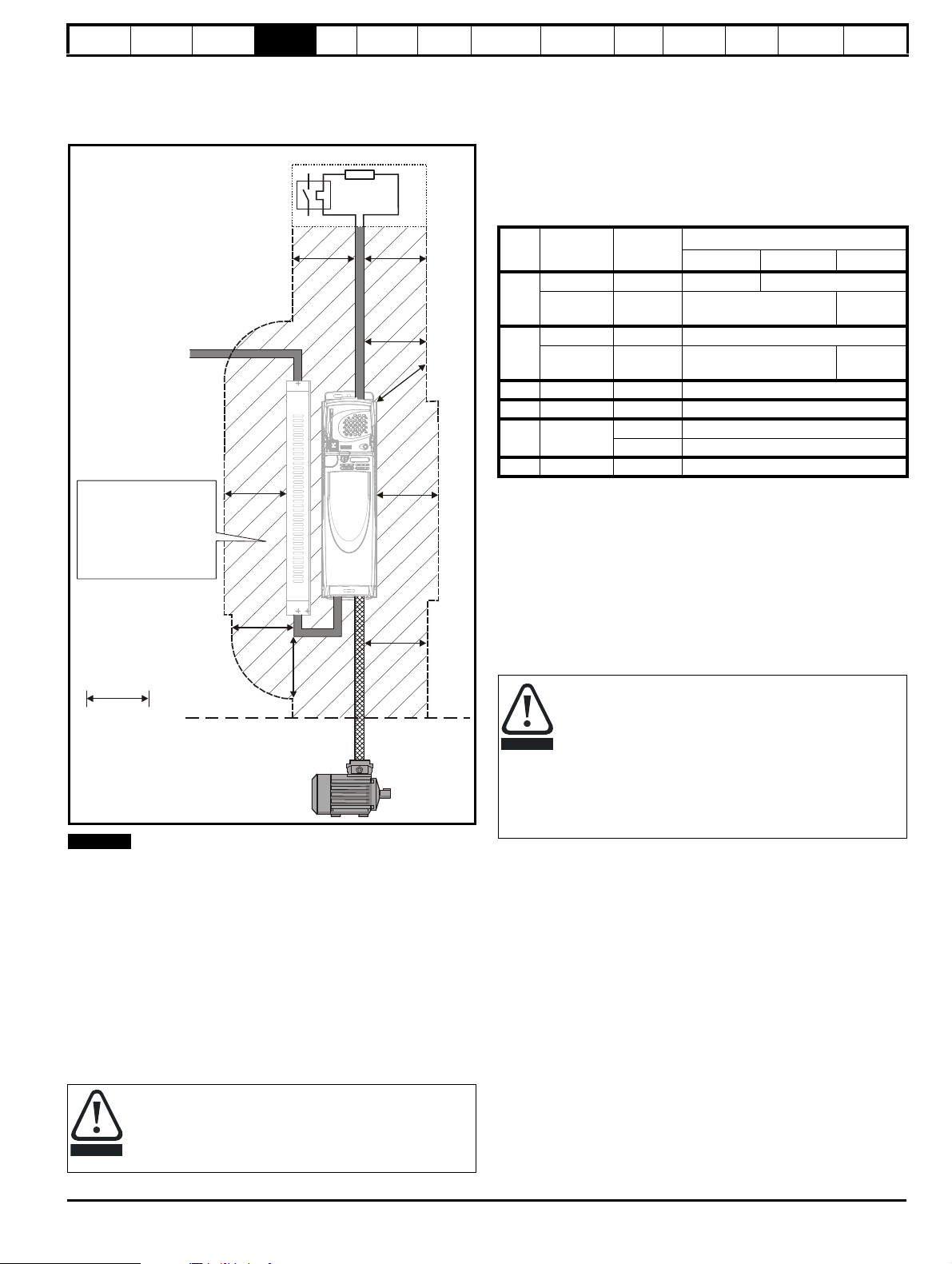
Safety
Optional braking resistor and overload
Do not place sensitive
(unscreened) signal circuits
in a zone extending
300mm (12”) all around the
Drive, motor cable, input
cable from EMC filter and
unshielded braking resistor
cable (if used)
300mm
(12in)
NOTE
CAUTION
CAUTION
Information
Cable layout
Figure 4-23 indicates the clearances which should be observed around
the drive and related ‘noisy’ power cables by all sensitive control signals
/ equipment.
Figure 4-23 Drive cable clearances
Any signal cables which are carried inside the motor cable (i.e. motor
thermistor, motor brake) will pick up large pulse currents via the cable
capacitance. The shield of these signal cables must be connected to
ground close to the motor cable, to avoid this noise current spreading
through the control system.
4.11.4 Compliance with EN 61800-3:2004 (standard
Meeting the requirements of this standard depends on the environment
that the drive is intended to operate in, as follows:
Operation in the first environment
Observe the guidelines given in section 4.11.5 Compliance with generic
emission standards on page 84. An external EMC filter will always be
required.
Product
Information
Mechanical
Installation
Electrical
Installation
N
for Power Drive Systems)
Getting
Star ted
Basic
parameters
Running
the motor
Optimization
SMARTCARD
operation
PC tools
Advanced
parameters
Technical
Data
Diagnostics
Information
Operation in the second environment
In all cases a shielded motor cable must be used, and an EMC filter is
required for all Affinity drives with a rated input current of less than 100A.
The drive contains an in-built filter for basic emission control. In some
cases feeding the motor cables (U, V and W) once through a ferrite ring
can maintain compliance for longer cable lengths. The requirements of
operating in the second environment are met, depending on the motor
cable length for 3kHz switching frequency as stated in Table 4-15.
Table 4-15 Second environment emission compliance
Drive
size
Filter Voltage
Motor cable length (m)
0 to 4 4 to 10 10 to 100
In-built Any Unrestricted Restricted
1
In-built and
ferrite ring
Any Unrestricted Restricted
In-built Any Restricted
2
In-built and
ferrite ring
Any Unrestricted Restricted
3 In-built Any Restricted
4 In-built Any Restricted
5 In-built
200 & 400 Unrestricted
690 Restricted
6 In-built Any Unrestricted
Key:
Restricted:EN 61800-3:2004 second environment, restricted distribution
(Additional measures may be required to prevent
interference)
Unrestricted:EN 61800-3:2004 second environment, unrestricted
distribution
For longer motor cables, an external filter is required. Where a filter is
required, follow the guidelines in section 4.11.5 Compliance with generic
emission standards .
Where a filter is not required, follow the guidelines given in section
4.11.3 General requirements for EMC on page 82.
The second environment typically includes an industrial lowvoltage power supply network which does not supply
buildings used for residential purposes. Operating the drive in
this environment without an external EMC filter may cause
interference to nearby electronic equipment whose sensitivity
has not been appreciated. The user must take remedial
measures if this situation arises. If the consequences of
unexpected disturbances are severe, it is recommended that
the guidelines in section 4.11.5 Compliance with generic
emission standards be adhered to.
Refer to section 12.1.23 Electromagnetic compatibility (EMC) for further
information on compliance with EMC standards and definitions of
environments.
Detailed instructions and EMC information are given in the EMC Data
Sheet which is available from the supplier of the drive.
UL Listing
This is a product of the restricted distribution class according
to IEC 61800-3
In a residential environment this product may cause radio
interference in which case the user may be required to take
adequate measures.
Affinity User Guide 83
Issue Number: 5 www.controltechniques.com
Page 84

Safety
≥
100mm
(4in)
≥
100mm
(4in)
Do not modify
the filter wires
100mm (4in)
100mm
(4in)
100mm (4in)
Information
Product
Information
Mechanical
Installation
Electrical
Installation
Getting
Star ted
Basic
parameters
Running
the motor
4.11.5 Compliance with generic emission standards
The following information applies to frame sizes 1 to 5.
Size 6 upwards does not comply with the requirements of the generic
standards for radiated emission.
Size 6 complies with the requirements for conducted emission.
Use the recommended filter and shielded motor cable. Observe the
layout rules given in Figure 4-24. Ensure the AC supply and ground
cables are at least 100mm from the power module and motor cable.
Figure 4-24 Supply and ground cable clearance (size 1 to 3)
Optimization
SMARTCARD
operation
PC tools
Advanced
parameters
Technical
Data
Diagnostics
Figure 4-25 Supply and ground cable clearance (size 4 to 6)
UL Listing
Information
84 Affinity User Guide
www.controltechniques.com Issue Number: 5
Page 85

Safety
Sensitive
signal
cable
≥
300mm
(12in)
Ensure direct
metal contact
at drive and
filter mounting
points (any
paint must be
removed).
Motor cable shield
(unbroken) electrically
connected to and held
in place by grounding
clamp.
+DC BR
Optional external
braking resistor
Enclosure
+DC BR
Optional external
braking resistor
Enclosure
OR
Information
Product
Information
Mechanical
Installation
Electrical
Installation
Getting
Star ted
Basic
parameters
Running
the motor
Avoid placing sensitive signal circuits in a zone 300mm (12in) all around
the power module.
Figure 4-26 Sensitive signal circuit clearance
Optimization
SMARTCARD
operation
PC tools
Advanced
parameters
Technical
Data
Diagnostics
Information
Connect the shield of the motor cable to the ground terminal of the motor
frame using a link that is as short as possible and not exceeding 50mm
(2in) long. A full 360
°
termination of the shield to the terminal housing of
the motor is beneficial.
It is unimportant for EMC purposes whether the motor cable contains an
internal (safety) ground core, or there is a separate external ground
conductor, or grounding is through the shield alone. An internal ground
core will carry a high noise current and therefore it must be terminated
as close as possible to the shield termination.
Figure 4-28 Grounding the motor cable shield
UL Listing
Ensure good EMC grounding.
Figure 4-27 Grounding the drive, motor cable shield and filter
Unshielded wiring to the optional braking resistor(s) may be used,
provided the wiring does not run external to the enclosure. Ensure a
minimum spacing of 300mm (12in) from signal wiring and the AC supply
wiring to the external EMC filter. Otherwise this wiring must be shielded.
Figure 4-29 Shielding requirements of optional external braking
resistor
Affinity User Guide 85
Issue Number: 5 www.controltechniques.com
Page 86
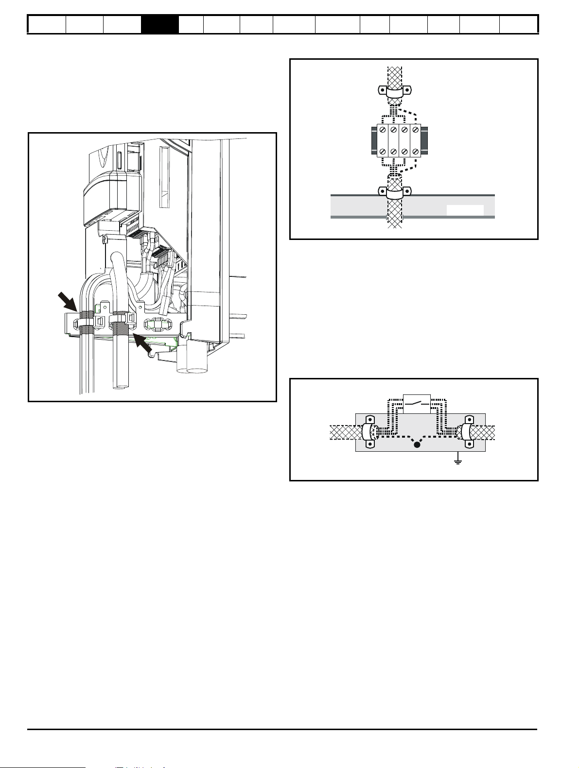
Safety
From
the
Drive
To the
motor
Back-plate
Enclosure
Isolator
Coupling bar
From the
Drive
To the
motor
(If
required)
Information
Product
Information
Mechanical
Installation
Electrical
Installation
Getting
Star ted
Basic
parameters
Running
the motor
If the control wiring is to exit the enclosure, it must be shielded and the
shield(s) clamped to the drive using the grounding bracket as shown in
Figure 4-30. Remove the outer insulating cover of the cable to ensure
the shield(s) make contact with the bracket, but keep the shield(s) intact
until as close as possible to the terminals
Alternatively, wiring may be passed through a ferrite ring, part no. 3225-
1004.
Figure 4-30 Grounding of signal cable shields using the
grounding bracket
Optimization
SMARTCARD
operation
PC tools
Advanced
parameters
Technical
Data
Diagnostics
UL Listing
Information
Figure 4-31 Connecting the motor cable to a terminal block in the
enclosure
Using a motor isolator / disconnect-switch
The motor cable shields should be connected by a very short conductor
having a low inductance. The use of a flat metal coupling-bar is
recommended; conventional wire is not suitable.
The shields should be bonded directly to the coupling-bar using
uninsulated metal cable-clamps. Keep the length of the exposed power
conductors to a minimum and ensure that all sensitive equipment and
circuits are at least 0.3m (12 in) away.
The coupling-bar may be grounded to a known low-impedance ground
nearby, for example a large metallic structure which is connected closely
to the drive ground.
Figure 4-32 Connecting the motor cable to an isolator /
disconnect switch
4.11.6 Variations in the EMC wiring
Interruptions to the motor cable
The motor cable should ideally be a single length of shielded or armored
cable having no interruptions. In some situations it may be necessary to
interrupt the cable, as in the following examples:
• Connecting the motor cable to a terminal block in the drive enclosure
• Installing a motor isolator / disconnect switch for safety when work is
done on the motor
In these cases the following guidelines should be followed.
Terminal block in the enclosure
The motor cable shields should be bonded to the back-plate using
uninsulated metal cable-clamps which should be positioned as close as
possible to the terminal block. Keep the length of power conductors to a
minimum and ensure that all sensitive equipment and circuits are at
least 0.3m (12 in) away from the terminal block.
Surge immunity of control circuits - long cables and
connections outside a building
The input/output ports for the control circuits are designed for general
use within machines and small systems without any special precautions.
These circuits meet the requirements of EN 61000-6-2:2005 (1kV surge)
provided the 0V connection is not grounded.
In applications where they may be exposed to high-energy voltage
surges, some special measures may be required to prevent malfunction
or damage. Surges may be caused by lightning or severe power faults in
association with grounding arrangements which permit high transient
voltages between nominally grounded points. This is a particular risk
where the circuits extend outside the protection of a building.
86 Affinity User Guide
www.controltechniques.com Issue Number: 5
Page 87

Safety
Signal from plant Signal to drive
0V 0V
30V zener diode
e.g. 2xBZW50-15
Signal from plant Signal to drive
0V 0V
2 x 15V zener diode
e.g. 2xBZW50-15
NOTE
1
8
Information
Product
Information
Mechanical
Installation
Electrical
Installation
Getting
Star ted
Basic
parameters
Running
the motor
As a general rule, if the circuits are to pass outside the building where
the drive is located, or if cable runs within a building exceed 30m, some
additional precautions are advisable. One of the following techniques
should be used:
1. Galvanic isolation, i.e. do not connect the control 0V terminal to
ground. Avoid loops in the control wiring, i.e. ensure every control
wire is accompanied by its return (0V) wire.
2. Shielded cable with additional power ground bonding. The cable
shield may be connected to ground at both ends, but in addition the
ground conductors at both ends of the cable must be bonded
together by a power ground cable (equipotential bonding cable) with
cross-sectional area of at least 10mm
2
, or 10 times the area of the
signal cable shield, or to suit the electrical safety requirements of the
plant. This ensures that fault or surge current passes mainly through
the ground cable and not in the signal cable shield. If the building or
plant has a well-designed common bonded network this precaution
is not necessary.
3. Additional over-voltage suppression - for the analog and digital
inputs and outputs, a zener diode network or a commercially
available surge suppressor may be connected in parallel with the
input circuit as shown in Figure 4-33 and Figure 4-34.
If a digital port experiences a severe surge its protective trip may operate
(O.Ld1 trip code 26). For continued operation after such an event, the
trip can be reset automatically by setting Pr 10.34 to 5.
Figure 4-33 Surge suppression for digital and unipolar inputs and
outputs
Optimization
SMARTCARD
operation
PC tools
Advanced
parameters
Technical
Data
Diagnostics
Information
Size 3-6
Custom holes have to be drilled for the power and motor cables. Suitable
glands should be installed to the gland plate, the cable passed through
the glands and the cable shield connected to ground inside the drive.
Alternatively EMC glands can be used.
If EMC glands are used they should rated to the required IP rating and
installed in accordance with the supplier's recommendations.
4.12 PC communications connections
4.12.1 Communications port
The drive has a serial communications port (serial port) as standard
supporting 2 wire EIA485 communications. Please see Table 4-16 for
the connection details for the RJ45 connector.
Figure 4-35 Location of the RJ45 serial comms connector
UL Listing
Figure 4-34 Surge suppression for analog and bipolar inputs and
outputs
Surge suppression devices are available as rail-mounting modules, e.g.
from Phoenix Contact:
Unipolar TT-UKK5-D/24 DC
Bipolar TT-UKK5-D/24 AC
These devices are not suitable for encoder signals or fast digital data
networks because the capacitance of the diodes adversely affects the
signal. Most encoders have galvanic isolation of the signal circuit from
the motor frame, in which case no precautions are required. For data
networks, follow the specific recommendations for the particular
network.
4.11.7 EMC wiring for E12/E54 and E12/E66 drives
Size 1-2
The gland plates have pre-prepared holes installed with grommets for
power and motor connection. The cable should pass through these and
the shield connected to ground using the supplied grounding clamp (see
section 4.11.1 Grounding hardware ). Alternatively the grommets can be
replaced with EMC glands.
Table 4-16 Connection details for RJ45 connector
Pin Function
1 120Ω Termination resistor
2RX TX
3 Isolated 0V
4 +24V (100mA)
5 Isolated 0V
6 TX enable
7RX\ TX\
8
RX\ TX\ (if termination resistors are required, link to pin 1)
Shell Isolated 0V
The communications port applies a 2 unit load to the communications
network.
Minimum number of connections are 2, 3, 7 and shield. Shielded cable
must be used at all times.
Affinity User Guide 87
Issue Number: 5 www.controltechniques.com
Page 88

Safety
WARNING
NOTE
WARNING
WARNING
CAUTION
Information
Product
Information
Mechanical
Installation
Electrical
Installation
Getting
Star ted
Basic
parameters
Running
the motor
Optimization
SMARTCARD
operation
PC tools
Advanced
parameters
Technical
Data
Diagnostics
UL Listing
Information
4.12.2 E12/E66 communications connection
The drive serial port is connected to an external RJ 45 connector on the
front of the drive, as shown in Figure 4-36 below.
The serial cable must be a shielded RJ45 cable with an appropriate
connector (suitable for mating with a Bulgin Buccaneer PX0833), rated
to a minimum of IP66.
If a cable is not connected then the connector cap must be installed as
shown in Figure 4-37.
Figure 4-36 Location of RJ45 serial connector
Figure 4-37 Connector with cap installed
4.12.3 Isolation of the communications port
The PC communications port is double insulated and meets the
requirements for SELV in EN 50178:1998.
In order to meet the requirements for SELV in IEC60950 (IT
equipment) it is necessary for the control computer to be
grounded. Alternatively, when a lap-top or similar device is
used which has no provision for grounding, an isolation
device must be incorporated in the communications lead.
N
When using the CT EIA232 Comms cable the available baud rate is
limited to 19.2k baud.
4.13 Terminal connections
4.13.1 General
Table 4-18 The terminal connections consist of:
Function Qty Control parameters available
Differential analog input 1
Single ended analog
input
Analog output 2 Source, mode, scaling, 9,10
Digital input 3 Destination, invert, logic select 27, 28, 29
Digital input / output 3
Building automation
network
Relay 1 Source, invert 41,42
Drive enable 1 31
+10V User output 1 4
+24V User output 1 Source, invert 22
0V common 6
+24V External input 1 2
Destination, offset, offset trim,
invert, scaling
Mode, offset, scaling, invert,
2
destination
Input / output mode select,
destination / source, invert,
logic select
5 35 to 39
Key:
Destination
parameter:
Source
parameter:
Mode
parameter:
indicates the parameter which is being controlled by the
terminal / function
indicates the parameter being output by the terminal
analog - indicates the mode of operation of the terminal,
i.e. voltage 0-10V, current 4-20mA etc.
digital - indicates the mode of operation of the terminal,
i.e. positive / negative logic (the Drive Enable terminal is
fixed in positive logic), open collector.
All analog terminal functions can be programmed in menu 7.
All digital terminal functions (including the relay) can be programmed in
menu 8.
The setting of Pr 1.14 and Pr 6.04 can cause the function of digital inputs
T25 to T29 to change. For more information, please refer to section
11.21.1 Reference modes on page 215.
The control circuits are isolated from the power circuits in the
drive by basic insulation (single insulation) only. The installer
must ensure that the external control circuits are insulated
from human contact by at least one layer of insulation
(supplementary insulation) rated for use at the AC supply
voltage.
If the control circuits are to be connected to other circuits
classified as Safety Extra Low Voltage (SELV) (e.g. to a
personal computer), an additional isolating barrier must be
included in order to maintain the SELV classification.
Ter mi nal
number
5,6
7,8
24, 25, 26
1, 3, 11, 21,
23, 30
An isolated serial communications lead has been designed to connect
the drive to IT equipment (such as lap-top computers), and is available
from the supplier of the drive. See below for details:
Table 4-17 Isolated serial comms lead details
Part number Description
If any of the digital inputs or outputs (including the drive
enable input) are connected in parallel with an inductive load
(i.e. contactor or motor brake) then suitable suppression (i.e.
diode or varistor) should be used on the coil of the load. If no
suppression is used then over voltage spikes can cause
damage to the digital inputs and outputs on the drive.
4500-0087 CT EIA232 Comms cable
4500-0096 CT USB Comms cable
The “isolated serial communications” lead has reinforced insulation as
defined in IEC60950 for altitudes up to 3,000m.
88 Affinity User Guide
www.controltechniques.com Issue Number: 5
Page 89
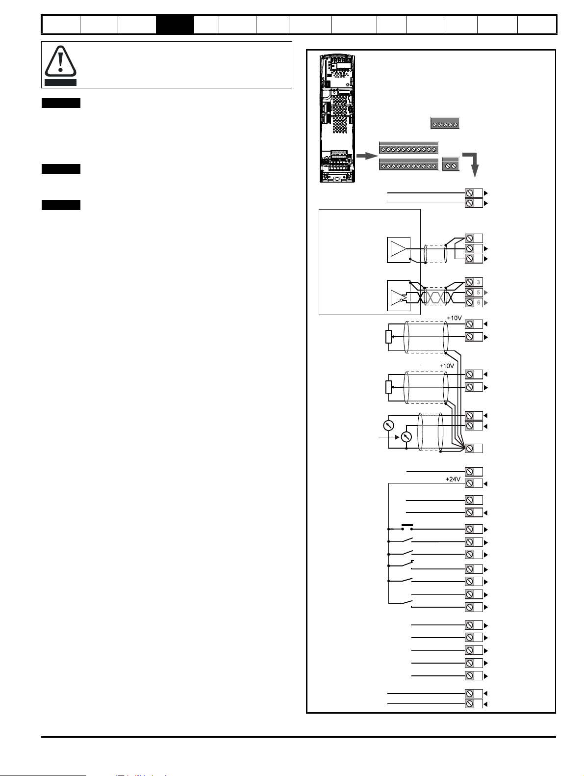
Safety
CAUTION
NOTE
NOTE
NOTE
1
11
Polarised
signal
connectors
21 31
41
42
0V common
External 24V supply
0V
common
Analog frequency/speed
reference 1
Connections for
single-ended
input
signal
Connections for
differential
input signal
0V common
0V common
0V common
Analog input 2
Analog input 1
0V
common
1
256321
22
232425
26
27282930314142
Drive active
Reset
Run forward
Fire mode activate
Analog input 1/
input 2 select
Spare
Drive enable*
Drive OK
Speed / frequency
0V common
Analog
frequency/speed
reference 2
4711910
Torque (active
current)
Analog
input 3
4
8
35 39
35
363738
39
A(+)
B(-)
GND
A(+)
B(-)
Building
Automation
Network
Relays (over voltage
category 11)
Information
Any signal cables which are carried inside the motor cable (i.e. motor
thermistor, motor brake) will pick up large pulse currents via the cable
capacitance. The shield of these signal cables must be connected to
ground close to the point of exit of the motor cable, to avoid this noise
current spreading through the control system.
The drive enable terminal is a positive logic input only. It is not affected
by the setting of Pr 8.29 Positive logic select.
The common 0V from analog signals should, wherever possible, not be
connected to the same 0V terminal as the common 0V from digital
signals. Terminals 3 and 11 should be used for connecting the 0V
common of analog signals and terminals 21, 23 and 30 for digital
signals. This is to prevent small voltage drops in the terminal
connections causing inaccuracies in the analog signals.
Product
Information
Mechanical
Installation
Electrical
Installation
Getting
Star ted
Basic
parameters
Running
the motor
Ensure the logic sense is correct for the control circuit to be
used. Incorrect logic sense could cause the motor to be
started unexpectedly.
Positive logic is the default state for Affinity drive.
N
N
N
Optimization
SMARTCARD
operation
PC tools
Advanced
parameters
Figure 4-38 Default terminal functions
Technical
Data
Diagnostics
UL Listing
Information
Affinity User Guide 89
Issue Number: 5 www.controltechniques.com
*The Drive enable terminal is a positive logic input only.
Page 90

Safety
Information
Product
Information
Mechanical
Installation
Electrical
Installation
Getting
Star ted
Basic
parameters
Running
the motor
4.13.2 Control terminal specification
1 0V common
Function
2 +24V external input
Function
Nominal voltage +24.0Vdc
Minimum continuous operating
voltage
Maximum continuous operating
voltage
Minimum start-up voltage 21.6Vdc
Recommended power supply 60W 24Vdc nominal
Recommended fuse 3A, 50Vdc
3 0V common
Function
4 +10V user output
Function Supply for external analog devices
Voltage tolerance ±1%
Nominal output current 10mA
Protection Current limit and trip @ 30mA
Precision reference Analog input 1
5 Non-inverting input
6 Inverting input
Default function Frequency/speed reference
Type of input
Full scale voltage range ±9.8V ±1%
Absolute maximum
voltage range
Working common mode voltage
range
Input resistance
Resolution 16-bit plus sign (as speed reference)
Monotonic Yes (including 0V)
Dead band None (including 0V)
Jumps None (including 0V)
Maximum offset
Maximum non linearity 0.3% of input
Maximum gain asymmetry 0.5%
Input filter bandwidth single pole ~1kHz
Sampling period
Common connection for all external
devices
To supply the control circuit
without providing a supply to the
power stage
+19.2Vdc
+30.0Vdc
Common connection for all external
devices
Bipolar differential analog
(For single-ended use, connect terminal 6
to terminal 3)
±36V relative to 0V
±13V relative to 0V
Ω ±1%
100k
700
μV
250
μs with destinations as Pr 1.36, Pr 1.37
3.22 in RFC mode. 4ms for open loop
or Pr
mode and all other destinations in RFC
mode.
Optimization
SMARTCARD
operation
PC tools
Advanced
parameters
Technical
Data
7 Analog input 2
Default function Frequency/speed reference
Type of input
Mode controlled by... Pr
Operating in Voltage mode
Full scale voltage range ±9.8V ±3%
Maximum offset ±30mV
Absolute maximum voltage range ±36V relative to 0V
Input resistance
Operating in current mode
Current ranges
Maximum offset
Absolute maximum voltage
(reverse bias)
Absolute maximum current +70mA
Equivalent input resistance
Common to all modes
Resolution 10 bit + sign
Sample period
Bipolar single-ended analog voltage or
unipolar current
7.11
>100k
Ω
0 to 20mA ±5%, 20 to 0mA ±5%,
4 to 20mA ±5%, 20 to 4mA ±5%
250
μA
−36V max
Ω at 20mA
≤200
μs when configured as voltage input
250
with destinations as Pr
Pr
3.22 or Pr 4.08 in RFC mode. 4ms for
open loop mode, all other destinations in
RFC mode or any destination when
configured as a current input.
8 Analog input 3
Default function Not configured
Type of input
Mode controlled by... Pr
Operating in Voltage mode (default)
Voltage range ±9.8V ±3%
Maximum offset ±30mV
Absolute maximum voltage range ±36V relative to 0V
Input resistance
Operating in current mode
Current ranges
Maximum offset
Absolute maximum voltage
(reverse bias)
Absolute maximum current +70mA
Equivalent input resistance
Operating in thermistor input mode
Internal pull-up voltage <5V
Trip threshold resistance
Reset resistance
Short-circuit detection resistance
Common to all modes
Resolution 10 bit + sign
Sample period
Bipolar single-ended analog voltage,
unipolar current or motor thermistor input
7.15
Ω
>100k
0 to 20mA ±5%, 20 to 0mA ±5%,
4 to 20mA ±5%, 20 to 4mA ±5%
μA
250
−36V max
Ω at 20mA
≤200
Ω ±10%
3.3k
Ω ±10%
1.8k
Ω ±40%
50
μs when configured as voltage input
250
with destinations as Pr
3.22 or Pr 4.08 in RFC mode. 4ms for
Pr
open loop mode, all other destinations in
RFC mode or any destination when
configured as a current input.
Diagnostics
1.36, Pr 1.37,
1.36, Pr 1.37,
UL Listing
Information
90 Affinity User Guide
www.controltechniques.com Issue Number: 5
Page 91

Safety
Information
Product
Information
Mechanical
Installation
Electrical
Installation
Getting
Star ted
Basic
parameters
Running
the motor
Optimization
SMARTCARD
operation
PC tools
Advanced
parameters
Technical
Data
Diagnostics
UL Listing
Information
9 Analog output 1
10 Analog output 2
Terminal 9 default function
Terminal 10 default function Motor active current
Type of output
Mode controlled by... Pr
Operating in Voltage mode (default)
Voltage range ±10V +3%
Maximum offset ±200mV
Maximum output current ±35mA
Load resistance
Protection 35mA max. Short circuit protection
Operating in current mode
Current ranges
Maximum offset
Maximum open circuit voltage +15V
Maximum load resistance
Common to all modes
Resolution 10-bit (plus sign in voltage mode)
Update period
OL> Motor FREQUENCY output signal
CL> SPEED output signal
Bipolar single-ended analog voltage or
unipolar single ended current
7.21 and Pr 7.24
Ω min
1k
0 to 20mA±5%
4 to 20mA ±5%
μA
600
600
Ω
250
μs when configured as a high speed
output with sources as Pr
all modes or Pr
4ms when configured as any other type of
output or with all other sources.
3.02, Pr 5.03 in RFC mode.
4.02, Pr 4.17 in
24 Digital I/O 1
25 Digital I/O 2
26 Digital I/O 3
Terminal 24 default function DRIVE ACTIVE output
Terminal 25 default function DRIVE RESET input
Terminal 26 default function RUN FORWARD input
Type
Input / output mode controlled by... Pr
Operating as an input
Logic mode controlled by... Pr 8.29
Absolute maximum applied voltage
range
Impedance
Input thresholds 10.0V ±0.8V
Operating as an output
Open collector outputs selected Pr 8.30
Nominal maximum output current 200mA (total including terminal 22)
Maximum output current 240mA (total including terminal 22)
Common to all modes
Voltage range 0V to +24V
Sample / Update period
Positive or negative logic digital inputs,
positive or negative logic push-pull outputs
or open collector outputs
8.31, Pr 8.32 and Pr 8.33
±30V
6k
Ω
μs when configured as an input with
250
destinations as Pr
when configured as an input with
destination as Pr
cases.
6.35 or Pr 6.36. 600μs
6.29. 4ms in all other
11 0V common
Function
Common connection for all external
devices
21 0V common
Function
Common connection for all external
devices
22 +24V user output (selectable)
Terminal 22 default function +24V user output
Can be switched on or off to act as a fourth
Programmability
Nominal output current 200mA (including all digital I/O)
Maximum output current 240mA (including all digital I/O)
Protection Current limit and trip
digital output (positive logic only) by setting
the source Pr
8.18
8.28 and source invert Pr
23 0V common
Function
Common connection for all external
devices
27 Digital Input 4
28 Digital Input 5
29 Digital Input 6
Terminal 27 default function FIRE MODE ACTIVATE input
Terminal 28 default function Analog INPUT 1 / INPUT 2 select
Terminal 29 default function Unassigned input
Type Negative or positive logic digital inputs
Logic mode controlled by... Pr
Voltage range 0V to +24V
Absolute maximum applied voltage
range
Impedance
Input thresholds 10.0V ±0.8V
Sample / Update period
8.29
±30V
Ω
6k
250
μs with destinations as Pr 6.35 or
Pr
6.36. 600μs with destination as Pr 6.29.
4ms in all other cases.
30 0V common
Function
Common connection for all external
devices
31 Drive enable
Type Positive logic only digital input
Voltage range 0V to +24V
Absolute maximum applied voltage ±30V
Thresholds 15.5V ±2.5V
Response time
Nominal: 8ms
Maximum: 20ms
Affinity User Guide 91
Issue Number: 5 www.controltechniques.com
Page 92
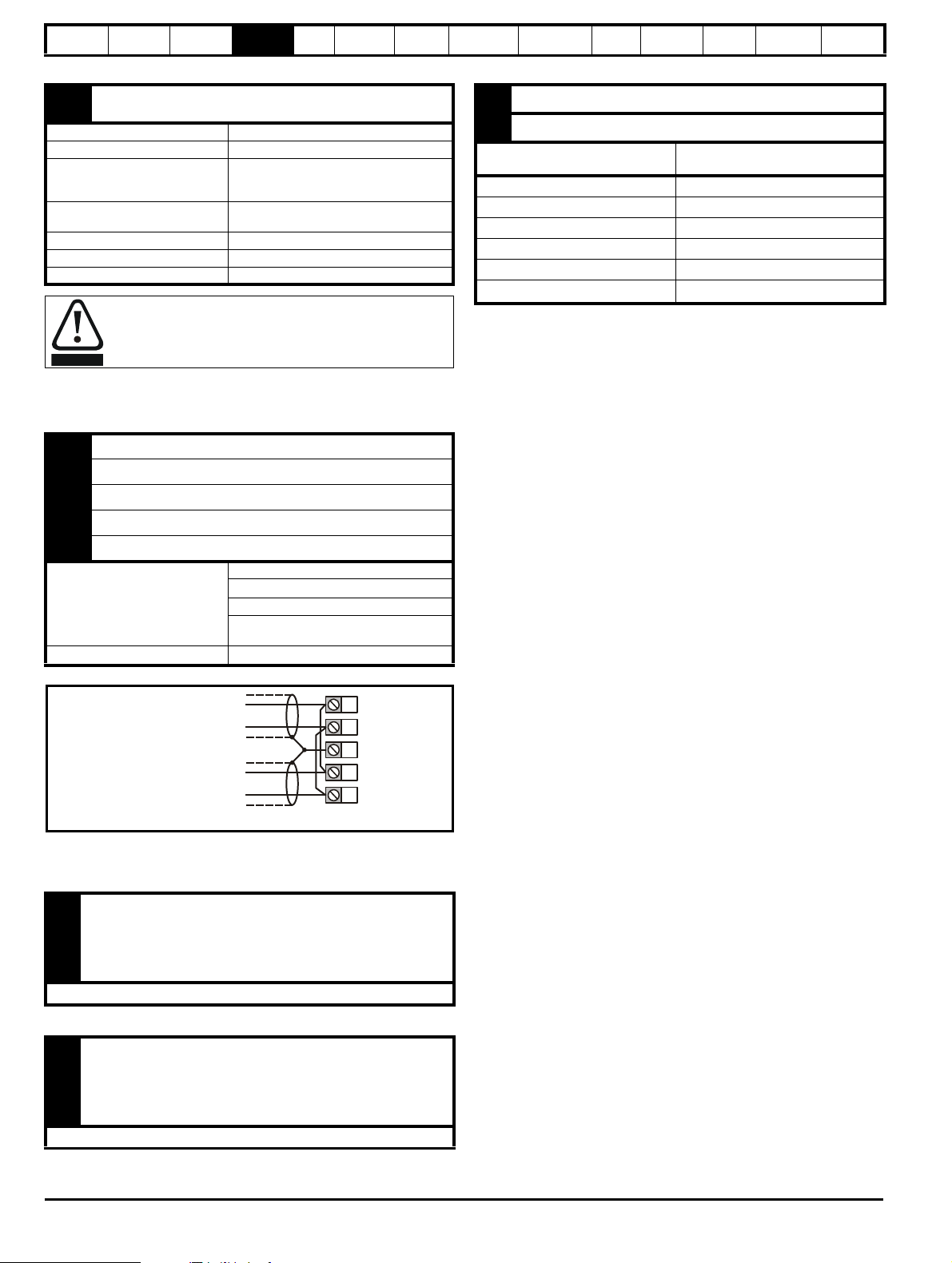
Safety
WARNING
39
38
37
36
35
B-
A+
B-
Previous node
Next node
(Fit 120 resistor if
end of network)
Ω
Isolated ground
A+
Information
Product
Information
Mechanical
Installation
Electrical
Installation
Getting
Star ted
Basic
parameters
Running
the motor
Optimization
SMARTCARD
operation
PC tools
Advanced
parameters
Technical
Data
Diagnostics
UL Listing
Information
41
Relay contacts
42
Default function Drive OK indicator
Contact voltage rating 240Vac, Installation over-voltage category II
Contact maximum current rating
Contact minimum recommended
rating
Contact type Normally open
Default contact condition Closed when power applied and drive OK
Update period 4ms
2A AC 240V
4A DC 30V resistive load
0.5A DC 30V inductive load (L/R = 40ms)
12V 100mA
A fuse or other over-current protection should be installed to
the relay circuit.
4.14 Building automation network connections
35 Previous node A(+)
36 Previous node B (-)
37 Isolated ground
38 Next node A(+)
39 Next node B(-)
Shielded twisted pair
Cable specification
Termination resistor
Characteristic impedance: 100 to 130
Capacitance between conductors: <100 pF
Maximum length: 1200m with AWG 18
cable
120
Figure 4-39 Multi-drop connection
Ω
Ω
64 0V
65 24V heatsink fan supply
Function
Nominal voltage 24Vdc
Minimum continuous operating voltage 23.5V
Maximum continuous operating voltage 27V
Current consumption 3.3A
Recommended power supply 24V, 100W, 4.5A
Recommended fuse
To provide the power supply to the
heatsink mounted fan
4A fast blow (I
2
t less than 20A2s)
4.15 Heatsink fan supply connections (size 4 to 6)
52
53
Heatsink fan connections (pre-wired)
54
55
No user connections
4.15.1 Heatsink fan supply connections (size 6 only)
60
61
No connection
62
63
No user connections
92 Affinity User Guide
www.controltechniques.com Issue Number: 5
Page 93

Safety
Mode (black) button
Joypad
Auto (blue) button
Off/reset (red) button
Hand (green) button
Control buttons
Help button
Auto
Hand
Off
Reset
NOTE
Information
Product
Information
Mechanical
Installation
Electrical
Installation
Getting
Started
Basic
parameters
Running
the motor
Optimization
SMARTCARD
operation
PC tools
Advanced
parameters
Technical
Data
Diagnostics
UL Listing
Information
5 Getting started
This chapter introduces the user interfaces, menu structure and security level of the drive.
5.1 Understanding the display
There is one keypad available for the Affinity. The BA-Keypad has an LCD display and is installed on the drive as standard.
5.1.1 BA-Keypad (LCD)
The display consists of three lines of text.
The top line shows the drive status or the current menu and parameter number being viewed on the left, and the parameter value or the specific trip
type on the right.
The lower two lines show the parameter name or the help text.
Figure 5-1 BA-Keypad
The red off button is also used to reset the drive.
The BA-Keypad Plus can indicate when a SMARTCARD access is taking place, when the second motor map is active (menu 21) or when solution
module parameters are displayed. These are indicated on the displays as follows.
Event Keypad
SMARTCARD access taking place The symbol ‘CC’ will appear in the lower left hand corner of the display
Second motor map active The symbol ‘Mot2’ will appear in the lower left hand corner of the display
Solutions module parameters displayed The symbol ‘Opx’ will appear in the left hand corner of the display
5.2 Keypad operation
5.2.1 Control buttons
The keypad consists of:
1. Joypad - used to navigate the parameter structure and change parameter values.
2. Mode button - used to change between the display modes – parameter view, parameter edit, status.
3. Three control buttons - used to select Hand / Off / Auto modes
4. Help button - displays text briefly describing the selected parameter.
The Help button toggles between other display modes and parameter help mode. The up and down functions on the joypad scroll the help text to
allow the whole string to be viewed. The right and left functions on the joypad have no function when help text is being viewed.
Affinity User Guide 93
Issue Number: 5 www.controltechniques.com
Page 94

Safety
Use
* keys
to select parameter for editing
To enter Edit Mode,
press key
Status
Mode
(Display
not
flashing)
Parameter
Mode
(Parameter
number
on upper
line
flashing)
Edit Mode
(Flashing character on upper line to be edited)
Change parameter values
using keys.
When returning
to Parameter
Mode use the
keys to select
another parameter
to change, if
required
To exit Edit Mode,
press key
To enter Parameter
Mode, press key or
*
Temporary
Parameter
Mode
(Parameter
number
on upper line
flashing)
Timeout**
Timeout**
To return to
Status Mode,
press
key
rdy 0
rpm
Est imat ed mot or
RPM
0. 1 0 0
rpm
Est imat ed mot or
RPM
0. 0 0 0
Fr e q u e c yn
Re f e r e c ens
0. 0 0 0
Fr e q u e c yn
Re f e r e c ens
0. 0 0 0
Fr e q u e c y
nReferecens
Timeout**
RO
parameter
R/W
parameter
Pr value
5.05
Menu 5. Parameter 5
Trip Status
Alarm Status
Parameter
View Mode
Healthy Status
Status Mode
5.0 5 7
DC B
us Vot
age
35
l
rdy 0
rpm
Est imated motor
RPM
run
rpm
Est imated motor
RPM
Ov e r Ld
rip
U
UnderVltage
t
U
oTipr
Auto
Hand
Off
Reset
Auto
Hand
Off
Reset
Auto
Hand
Off
Reset
Auto
Hand
Off
Reset
WARNING
NOTE
NOTE
*
*
.000
.111
.101
.00
2
.091
Information
Product
Information
Mechanical
Installation
Figure 5-2 Display modes
Electrical
Installation
Getting
Started
Basic
parameters
Running
the motor
Optimization
SMARTCARD
operation
PC tools
Advanced
parameters
Technical
Data
Diagnostics
UL Listing
Information
* Can only be used to move between menus if L2 access has been enabled (Pr 0.49). Refer to section 5.10 on page 97.
**Timeout defined by Pr 11.41 (default value = 240s).
Figure 5-3 Mode examples
Do not change parameter values without careful
consideration; incorrect values may cause damage or a
safety hazard.
When changing the values of parameters, make a note of the new
values in case they need to be entered again.
For new parameter-values to apply after the AC supply to the drive is
interrupted, new values must be saved. Refer to section 5.8 Saving
parameters on page 97.
5.3 Menu structure
The drive parameter structure consists of menus and parameters.
The drive initially powers up so that only menu 0 can be viewed. The up
and down arrow buttons are used to navigate between parameters and
once level 2 access (L2) has been enabled (see Pr 0.49) the left and
right buttons are used to navigate between menus. For further
94 Affinity User Guide
www.controltechniques.com Issue Number: 5
information, refer to section 5.10 Parameter access level and security on
page 97.
Figure 5-4 Parameter navigation
* Can only be used to move between menus if L2 access has
The menus and parameters roll over in both directions.
been enabled (Pr 0.49). Refer to section 5.10 Parameter
access level and security on page 97.
Page 95

Safety
Menu 0
....XX.00....
0.50
0.49
0.48
0.47
0.46
0.01
0.02
0.03
0.04
0.05
Moves
between
parameters
M
e
n
u
4
1
M
e
n
u
1
M
e
n
u
2
M
e
n
u
4
0
Moves between Menus
4
1
.
5
0
4
1
.
4
9
4
1
.
4
8
4
1
.
4
7
4
1
.
4
6
4
1
.
0
1
4
1
.
0
2
4
1
.
0
3
4
1
.
0
4
4
1
.
0
5
1
.
0
1
1
.
0
2
1
.
0
3
1
.
0
4
1
.
0
5
1
.
5
0
1
.
4
9
1
.
4
8
1
.
4
7
1
.
4
6
Menu 0
0.04
0.05
0.06
Menu 2
2.21
Menu 1
1.14
Menu 4
4.07
5
0
150
0
150
5
Information
Product
Information
Mechanical
Installation
Electrical
Installation
Getting
Started
Basic
parameters
Running
the motor
i.e. if the last parameter is displayed, a further press will cause the
display to rollover and show the first parameter.
When changing between menus the drive remembers which parameter
was last viewed in a particular menu and thus displays that parameter.
Figure 5-5 Menu structure
Optimization
SMARTCARD
operation
PC tools
Advanced
parameters
Technical
Data
Diagnostics
5.5 Advanced menus
The advanced menus consist of groups or parameters appropriate to a
specific function or feature of the drive.
Table 5-1 Advanced menu descriptions
Menu Description
Commonly used basic set up parameters for quick / easy
0
programming
1 Frequency / speed reference
2Ramps
3 Slave frequency, speed feedback and speed control
4 Torque and current control
5 Motor control
6 Sequencer and clock
7 Analog I/O
8 Digital I/O
9 Programmable logic, motorized pot and binary sum
10 Status and trips
11 General drive set-up
12 Threshold detectors and variable selectors
14 User PID controller
15, 16 Solutions Module set-up
17 Building automation network
18 Application menu 1
19 Application menu 2
20 Application menu 3
21 Second motor parameters
22 Additional Menu 0 set-up
40 Keypad configuration menu
41 User filter menu
UL Listing
Information
5.5.1 Keypad set-up menus
5.4 Menu 0
Menu 0 is used to bring together various commonly used parameters for
basic easy set up of the drive.
Appropriate parameters are copied from the advanced menus into menu
0 and thus exist in both locations.
For further information, refer to Chapter 6 Basic parameters on
page 102.
Figure 5-6 Menu 0 copying
Affinity User Guide 95
Issue Number: 5 www.controltechniques.com
Table 5-2 Menu 40 parameter descriptions
Parameter
Range(
40.00 Parameter 0 0 to 32767
English (0), Custom (1),
40.01 Language selection
French (2), German (3),
Spanish (4), Italian (5)
40.02 Software version
40.03 Save to flash
40.04 LCD contrast
Drive and attribute database
40.05
upload was bypassed
40.06 Browsing favourites control
40.07 Keypad security code
Communication channel
40.08
selection
40.09 Hardware key code
40.10 Drive node ID (Address)
40.11 Flash ROM memory size
String database version
40.19
number
Screen saver strings and
40.20
enable
40.21 Screen saver interval
40.22 Turbo browse time interval
Idle (0), Save (1), Restore (2),
Disable (0), Slot1 (1), Slot2 (2),
Slot3 (3), Slave (4), Direct (5)
None (0), Default (1), User (2)
999999
Default (3)
0 to 31
Updated (0), Bypass (1)
Normal (0), Filter (1)
0 to 999
0 to 999
0 to 255
4Mbit (0), 8Mbit (1)
0 to 999999
0 to 600
0 to 200ms
Unidrive SP (0), Commander
40.23 Product identification
SK (1), Mentor MP (2),
Commander GP20 (3)
Affinity (4), Digitax (5)
Ú)
Page 96

Safety
Information
Product
Information
Mechanical
Installation
Electrical
Installation
Getting
Started
Basic
parameters
Running
the motor
Table 5-3 Menu 41 parameter descriptions
Parameter
Range(
Ú)
41.00 Parameter 0 0 to 32767
41.01
to
Browsing filter source F01 to F50 Pr 0.00 to Pr 391.51
41.50
41.51 Browsing favourites control Normal (0), Filter (1)
5.5.2 Display messages
The following tables indicate the various possible mnemonics which can
be displayed by the drive and their meaning.
Trip types are not listed here but can be found in Chapter 6 Basic
parameters on page 102 if required.
Table 5-4 Alarm indications
Lower
display
br.rS Braking resistor overload
Braking resistor I
2
t accumulator (Pr 10.37) in the drive has reached
75.0% of the value at which the drive will trip and the braking IGBT is
active.
Hot
Heatsink or control board or inverter IGBT over
temperature alarms are active
• The drive heatsink temperature has reached a threshold and the
drive will trip ‘Oh2’ if the temperature continues to rise (see the
‘Oh2’ trip).
or
• The ambient temperature around the control PCB is approaching
the over temperature threshold (see the ‘O.CtL’ trip).
OVLd Motor overload
The motor I
2
t accumulator in the drive has reached 75% of the value at
which the drive will be tripped and the load on the drive is >100%
Auto tune Autotune in progress
The autotune procedure has been initialised. 'Auto' and 'tunE' will flash
alternatively on the display.
Lt Limit switch is active
Indicates that a limit switch is active and that it is causing the motor to
be stopped (i.e. forward limit switch with forward reference etc.)
PLC Onboard PLC program is running
An Onboard PLC program is installed and running. The display will
flash 'PLC' once every 10s.
Description
Optimization
SMARTCARD
operation
PC tools
Advanced
parameters
Technical
Data
Diagnostics
Information
Table 5-5 Status indications
Upper
display
Description
Drive output
stage
ACUU AC Supply loss
The drive has detected that the AC supply has been
lost and is attempting to maintain the DC bus voltage
Enabled
by decelerating the motor.
Auto Auto mode
The drive is running in Auto mode
dc DC applied to the motor
The drive is applying DC injection braking.
dEC Decelerating
The drive is decelerating the motor.
Hand Hand mode
The drive is running in Hand mode
Heat Motor pre-heat
Motor pre-heat active
inh
Inhibit
The drive is inhibited and cannot be run.
The drive enable signal is not applied to terminal 31 or
Enabled
Enabled
Enabled
Enabled
Enabled
Disabled
Pr 6.15 is set to 0.
Off Drive is stopped
Drive is stopped
Disabled
run Drive running
Drive is running with Hand / Off / Auto functions
Enabled
disabled
rdY Ready
The drive is ready to be run.
StoP Stop or holding zero speed
The drive is holding zero speed.
Disabled
Enabled
triP Trip condition
The drive has tripped and is no longer controlling the
motor. The trip code appears on the right hand side of
Disabled
the top row of the display.
Table 5-6 Solutions Module and SMARTCARD status indications
on power-up
Lower
display
Description
boot
A parameter set is being transferred from the SMARTCARD to the
drive during power-up. For further information, please refer to section
9.2.4 Booting up from the SMARTCARD on every power up (Pr 11.42 =
boot (4)) on page 131.
cArd
The drive is writing a parameter set to the SMARTCARD during powerup.
For further information, please refer to section 9.2.3 Auto saving
parameter changes (Pr 11.42 = Auto (3)) on page 131.
loAding
The drive is writing information to a Solutions Module.
UL Listing
96 Affinity User Guide
www.controltechniques.com Issue Number: 5
Page 97

Safety
0.4 8 PLPOnE
0.4 8 frc
NOTE
Information
Product
Information
Mechanical
Installation
Electrical
Installation
Getting
Started
Basic
parameters
Running
the motor
Optimization
SMARTCARD
operation
PC tools
Advanced
parameters
Technical
Data
Diagnostics
UL Listing
Information
5.6 Changing the operating mode
Changing the operating mode returns all parameters to their default
value, including the motor parameters. (Pr 0.49 Security status and
Pr 0.34 User security code are not affected by this procedure.)
Procedure
Use the following procedure only if a different operating mode is
required:
1. Ensure the drive is not enabled, i.e. terminal 31 is open or Pr 6.15 is
Off (0)
2. Enter either of the following values in Pr xx.00, as appropriate:
1253 (EUR, 50Hz AC supply frequency)
1254 (USA, 60Hz AC supply frequency)
3. Change the setting of Pr 0.48 as follows:
The figures in the second column apply when serial communications are
used.
Pr 0.48 setting Operating mode
1 Open-loop
2RFC mode
4. Either:
• Press the red reset button
• Toggle the reset digital input
• Carry out a drive reset through serial communications by setting
Pr 10.38 to 100 (ensure that Pr. xx.00 returns to 0).
Entering 1253 or 1254 in Pr xx.00 will only load defaults if the setting of
Pr 0.48 has been changed.
5.7 Changing the keypad mode
The keypad mode can be selected for Hand, Off or Auto by using the
keypad buttons
• Blue - Auto
• Red - Off
• Green - Hand
In Hand mode, the motor speed is adjusted by pressing the keypad up/
down arrow buttons. If Hand mode is selected from Auto mode then the
transition is bumpless, so the motor speed will not change.
In Auto mode, the motor speed control reference is determined by the
value set in the speed/frequency reference selector Pr 0.05.
In Off mode, the motor will be stopped but pressing the keypad up/down
arrow buttons will allow the keypad control reference Pr 1.17 to be
adjusted. Selecting Hand mode will then ramp the motor up to the
selected speed.
Procedure
Enter 1000* in Pr. xx.00
Either:
• Press the red reset button
• Toggle the reset digital input
• Carry out a drive reset through serial communications by setting
Pr 10.38 to 100 (ensure that Pr. xx.00 returns to 0).
*If the drive is in the under voltage trip state or is being supplied from a
low voltage DC supply, a value of 1001 must be entered into Pr xx.00 to
perform a save function.
5.9 Restoring parameter defaults
Restoring parameter defaults by this method saves the default values in
the drive’s memory. (Pr 0.49 and Pr 0.34 are not affected by this
procedure.)
Procedure
1. Ensure the drive is not enabled, i.e. terminal 31 is open or Pr 6.15 is
Off (0)
2. Enter 1233 (EUR 50Hz settings) or 1244 (USA 60Hz settings) in
Pr xx.00.
3. Either:
• Press the red reset button
• Toggle the reset digital input
• Carry out a drive reset through serial communications by setting
Pr 10.38 to 100 (ensure that Pr. xx.00 returns to 0).
5.10 Parameter access level and security
The parameter access level determines whether the user has access to
menu 0 only or to all the advanced menus (menus 1 to 22) in addition to
menu 0.
The User Security determines whether the access to the user is read
only or read write.
Both the User Security and Parameter Access Level can operate
independently of each other as shown in the table below:
Parameter
Access Level
User Security
Menu 0
status
L1 Open RW Not visible
L1 Closed RO Not visible
L2 Open RW RW
L2 Closed RO RO
RW = Read / write access RO = Read only access
The default settings of the drive are Parameter Access Level L1 and
user Security Open, i.e. read / write access to Menu 0 with the advanced
menus not visible.
Advanced
menus status
5.8 Saving parameters
When changing a parameter in Menu 0, the new value is saved when
pressing the Mode button to return to parameter view mode from
parameter edit mode.
If parameters have been changed in the advanced menus, then the
change will not be saved automatically. A save function must be carried
out.
Affinity User Guide 97
Issue Number: 5 www.controltechniques.com
Page 98
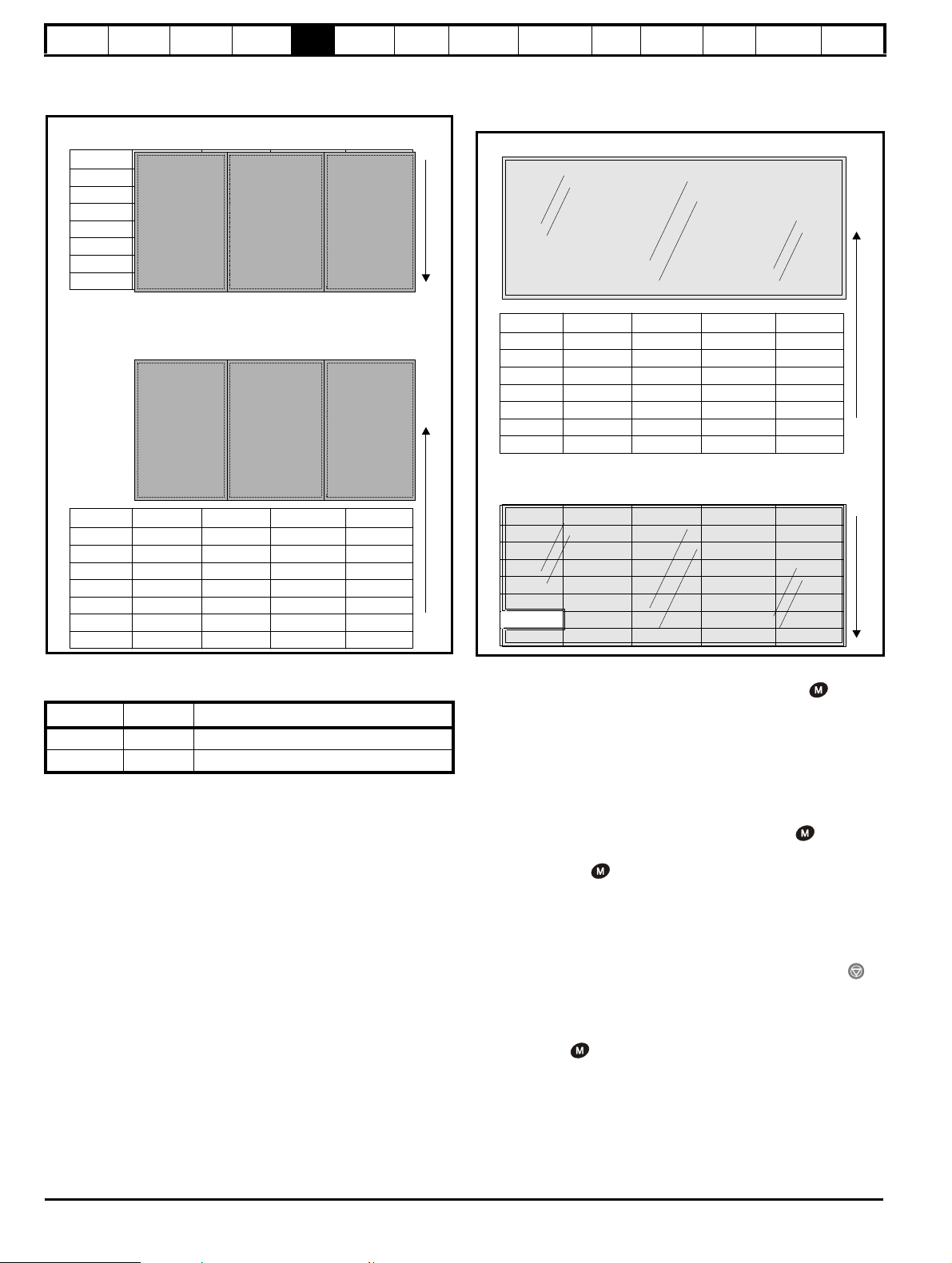
Safety
Pr 0.00
Pr 0.01
Pr 0.02
Pr 0.03
Pr 0.49
Pr 0.50
Pr 1.00
Pr 1.01
Pr 1.02
Pr 1.03
Pr 1.49
Pr 1.50
Pr 22.00
Pr 22.01
Pr 22.02
Pr 22.03
Pr 22.28
Pr 22.29
............
............
............
............
............
............
............
............
L2 access selected
- All parameters visible
Pr 0.00
Pr 0.01
Pr 0.02
Pr 0.03
Pr 0.49
Pr 0.50
Pr 1.00
Pr 1.01
Pr 1.02
Pr 1.03
Pr 1.49
Pr 1.50
Pr 19.00
Pr 19.01
Pr 19.02
Pr 19.03
Pr 19.49
Pr 19.50
Pr 20.00
Pr 20.01
Pr 20.02
Pr 20.03
Pr 20.49
Pr 20.50
............
............
............
............
............
............
............
............
L1 access selected
- Menu 0 only visible
Pr 21.00
Pr 21.01
Pr 21.02
Pr 21.03
Pr 21.30
Pr 21.31
Pr 0.00
Pr 0.01
Pr 0.02
Pr 0.03
Pr 0.50
Pr 1.00
Pr 1.01
Pr 1.02
Pr 1.03
Pr 1.49
Pr 1.50
............
............
............
............
............
............
............
............
Pr 0.00
Pr 0.01
Pr 0.02
Pr 0.03
Pr 0.49
Pr 0.50
Pr 1.00
Pr 1.01
Pr 1.02
Pr 1.03
Pr 1.49
Pr 1.50
Pr 22.00
Pr 22.01
Pr 22.02
Pr 22.03
Pr 22.28
Pr 22.29
............
............
............
............
............
............
............
............
User security open
- All parameters: Read / Write access
User security closed
0.49 11.44
- All parameters: Read Only access
(except Pr and Pr )
Pr 22.00
Pr 22.01
Pr 22.02
Pr 22.03
Pr 22.28
Pr 22.29
Pr 0.49
Pr 21.00
Pr 21.01
Pr 21.02
Pr 21.03
Pr 21.30
Pr 21.31
Pr 21.00
Pr 21.01
Pr 21.02
Pr 21.03
Pr 21.30
Pr 21.31
Information
Product
Information
Mechanical
Installation
Electrical
Installation
Getting
Started
Basic
parameters
Running
the motor
Optimization
SMARTCARD
operation
PC tools
Advanced
parameters
Technical
Data
Diagnostics
UL Listing
Information
5.10.1 Access Level
The access level is set in Pr 0.49 and allows or prevents access to the
advanced menu parameters.
5.10.3 User Security
The User Security, when set, prevents write access to any of the
parameters (other than Pr. 0.49 and Pr 11.44 Access Level) in any
menu.
5.10.2 Changing the Access Level
The Access Level is determined by the setting of Pr 0.49 as follows:
String Value Effect
L1 0 Access to menu 0 only
L2 1 Access to all menus (menu 0 to menu 22)
The Access Level can be changed through the keypad even if the User
Security has been set.
Setting User Security
Enter a value between 1 and 999 in Pr 0.34 and press the button;
the security code has now been set to this value. In order to activate the
security, the Access level must be set to Loc in Pr 0.49. When the drive
is reset, the security code will have been activated and the drive returns
to Access Level L1. The value of Pr 0.34 will return to 0 in order to hide
the security code. At this point, the only parameter that can be changed
by the user is the Access Level Pr 0.49.
Unlocking User Security
Select a read write parameter to be edited and press the button, the
display will now show CodE. Use the arrow buttons to set the security
code and press the button.
With the correct security code entered, the display will revert to the
parameter selected in edit mode.
If an incorrect security code is entered the display will revert to
parameter view mode.
To lock the User Security again, set Pr 0.49 to Loc and press the
reset button.
Disabling User Security
Unlock the previously set security code as detailed above. Set Pr 0.34 to
0 and press the button. The User Security has now been disabled,
and will not have to be unlocked each time the drive is powered up to
allow read / write access to the parameters.
98 Affinity User Guide
www.controltechniques.com Issue Number: 5
Page 99

Safety
Information
Product
Information
Mechanical
Installation
Electrical
Installation
Getting
Started
Basic
parameters
Running
the motor
Optimization
SMARTCARD
operation
PC tools
Advanced
parameters
Technical
Data
Diagnostics
UL Listing
Information
5.11 Displaying parameters with nondefault values only
By entering 12000 in Pr xx.00, the only parameters that will be visible to
the user will be those containing a non-default value. This function does
not require a drive reset to become active. In order to deactivate this
function, return to Pr xx.00 and enter a value of 0.
Please note that this function can be affected by the access level
enabled, refer to section 5.10 Parameter access level and security for
further information regarding access level.
5.12 Displaying destination parameters only
By entering 12001 in Pr xx.00, the only parameters that will be visible to
the user will be destination parameters. This function does not require a
drive reset to become active. In order to deactivate this function, return
to Pr xx.00 and enter a value of 0.
Please note that this function can be affected by the access level
enabled, refer to section 5.10 Parameter access level and security for
further information regarding access level.
5.13 Communications
5.13.1 Introduction
The Affinity has a PC communications interface and a Building
Automation Network interface. The PC communications interface
enables all drive set-up, operation and monitoring to be carried out with
a PC or controller if required. Therefore, it is possible to control the drive
entirely by serial communications without the need for a BA-keypad or
other control cabling. The PC communications interface supports two
protocols selected by parameter configuration:
• Modbus RTU
• CT ANSI
Modbus RTU has been set as the default protocol, as it is used with the
PC-tools commissioning/start-up software as provided on the CD ROM.
The PC communications port of the drive is a RJ45 socket, which is
isolated from the power stage and the other control terminals (see
section 4.12 PC communications connections for connection and
isolation details).
The communications port applies a 2 unit load to the communications
network.
USB/EIA232 to EIA485 Communications
An external USB/EIA232 hardware interface such as a PC cannot be
used directly with the 2-wire PC communications interface of the drive.
Therefore a suitable converter is required.
Suitable USB to EIA485 and EIA232 to EIA485 isolated converters are
available from Control Techniques as follows:
• CT USB Comms cable (CT Part No. 4500-0096)
• CT EIA232 Comms cable (CT Part No. 4500-0087)
When using one of the above converters or any other suitable converter
with the Affinity , it is recommended that no terminating resistors be
connected on the network. It may be necessary to 'link out' the
terminating resistor within the converter depending on which type is
used. The information on how to link out the terminating resistor will
normally be contained in the user information supplied with the
converter.
The Building Automation Network enables connection to a building
automation system using the following protocols:
• Modbus RTU slave
• BACnet
• Metasys N2
5.13.2 Building automation network communications set-up parameters
17.03 MAC/Node Address
RW Uni US
Ú
0 to 65535
Ö
Allowable MAC Address Values
Protocol
Master/
Slave
Minimum Maximum Broadcast
Modbus RTU Slave 1 247 0
BACnet Master 0 127 255
Metasys N2 Slave 1 255 0
If a MAC address is selected that is greater than that allowed by the
currently selected protocol then the actual address used will be the
maximum valid address value.
*The Affinity drive is a BACnet master device and as such will instigate IAm messages onto the BACnet network. These messages allow other
BACnet master devices to determine the capabilities of the Affinity drive.
17.04 Baud rate
RW Uni US
Ú
0 to 127
Ö
This selects the baud rate used for network communication.
Pr 17.04 value Baud rate (bps)
0 Protocol default value (see table below)
1 1200
2 2400
3 4800
4 9600
5 19200
6 38400
7 57600
8 76800
>8 Protocol default value (see table below)
The default value when Pr 17.04 is set to 0 or >8 is as follows:
Protocol Default baud rate (bps)
Modbus RTU 9600
BACnet 19200
Metasys N2 9600
17.05 Building Automation Network protocol
RW Uni US
Ú
0 to 65535
Ö
This selects the protocol used for the Building Automation Network as
follows:
17.05 Protocol
0 Disabled
1 Modbus RTU
2 BACnet
3 Metasys N2
If a value greater than 3 is entered for Pr 17.05 then the Building
Automation Network is disabled.
1
0
0
Affinity User Guide 99
Issue Number: 5 www.controltechniques.com
Page 100

Safety
NOTE
Information
Product
Information
Mechanical
Installation
Electrical
Installation
Getting
Started
Basic
parameters
Running
the motor
Optimization
SMARTCARD
operation
PC tools
Advanced
parameters
Technical
Data
Diagnostics
UL Listing
Information
17.10 Device Object Identifier
RW Bi US
Ú
-19 to 32767
Ö
0
BACnet use only
If Object Identifier is set to any value less than -19 (to -32768) then the
Pr 17.10 gets set to 1. If Object Identifier is set to zero then the MAC/
Node address selected in Pr 17.03 will be used as the object identifier
for the BACnet device; otherwise the device object identifier will be the
value specified here.
The BACnet Object Identifier range supported on Affinity drive is from 1
to 4194302 (supported on BAN firmware V01.03.07 or later). In order to
set the Object Identifier above 32767 two consecutive menu 18
parameters are used as shown in Table 5-7. Each pair of menu 18
parameters is selected using Pr 17.10; the lower parameter number will
contain the last four decimal digits of the Object Identifier and the higher
parameter number will contain the first three decimal digits of the Object
Identifier. The choice of which pair of parameters is used depends on the
availability of the parameters, as long as they are NOT used by any on
board PLC or DPL program they can be used.
This method can also be used to set object identifier values below 32768
if required.
Table 5-7 Increased Object Identifier range setup
Serial
No
Set value in
Pr 17.10
Enter last four
numbers from Object
Identifier
Enter first three
numbers from
Object Identifier
1 -1 Pr 18.11 Pr 18.12
2 -2 Pr 18.12 Pr 18.13
3 -3 Pr 18.13 Pr 18.14
4 -4 Pr 18.14 Pr 18.15
5 -5 Pr 18.15 Pr 18.16
6 -6 Pr 18.16 Pr 18.17
7 -7 Pr 18.17 Pr 18.18
8 -8 Pr 18.18 Pr 18.19
9 -9 Pr 18.19 Pr 18.20
10 -10 Pr 18.20 Pr 18.21
11 - 11 P r 18.21 Pr 18.22
12 -12 Pr 18.22 Pr 18.23
13 -13 Pr 18.23 Pr 18.24
14 -14 Pr 18.24 Pr 18.25
15 -15 Pr 18.25 Pr 18.26
16 -16 Pr 18.26 Pr 18.27
17 -17 Pr 18.27 Pr 18.28
18 -18 Pr 18.28 Pr 18.29
19 -19 Pr 18.29 Pr 18.30
Example 1: To set the value of the Object Identifier as 4194302 for an
Affinity drive; set the following parameters (provided Pr 18.29 and
Pr 18.30 are not used for DPL program and are available);
•Pr 17.10 set to -19
•Pr 18.29 set to 4302
•Pr 18.30 set to 419
Example 2: To set the value of the Object Identifier as 59430 for an
Affinity drive; set the parameters (provided Pr 18.11 and Pr 18.12 are not
used for DPL program and are available);
•Pr 17.10 set to -1
•Pr 18.11 set to 9430
•Pr 18.12 set to 5
17.38 Data format
RW Uni US
Ú
0 to 255
Ö
0
This selects the data transmission format used for the selected protocol.
17.38
Start bits Data bits Parity Stop bits
Description
0 Protocol default value (see table below)
1 1 8 None 1
2 1 8 None 2
318Even1
418Odd1
>4 Protocol default value (see table below)
The default value when Pr 17.38 is set to 0 or >4 is as follows:
Protocol
Start bits Data bits Parity Stop bits
Description
Modbus RTU 1 8 None 2
BACnet 1 8 None 1
Metasys N2 1 8 None 1
5.13.3 PC communications set-up parameters
The following parameters need to be set according to the system
requirements.
0.35 {11.24} PC comms mode
RW Txt US
Ú
AnSI (0)
rtU (1)
Ö
This parameter defines the communications protocol used by the 485
comms port on the drive. This parameter can be changed via the drive
keypad, via a Solutions Module or via the comms interface itself. If it is
changed via the comms interface, the response to the command uses
the original protocol. The master should wait at least 20ms before send a
new message using the new protocol. (Note: ANSI uses 7 data bits, 1
stop bit and even parity; Modbus RTU uses 8 data bits, 2 stops bits and
no parity.)
Comms value String Communications mode
0AnSI ANSI
1 rtU Modbus RTU protocol
2Lcd
Modbus RTU protocol, but with a
keypad only
ANSIx3.28 protocol
Full details of the CT ANSI communications protocol are the Advanced
User Guide.
Modbus RTU protocol
Full details of the CT implementation of Modbus RTU are given in the
Advanced User Guide.
Modbus RTU protocol, but with a keypad only
This setting is used for disabling communications access when the BAKeypad is used as a hardware key. See the Advanced User Guide for
more details.
rtU (1)
After setting the required Object Identifier, save the changes on the drive
Pr XX.00 = 1000.
100 Affinity User Guide
www.controltechniques.com Issue Number: 5
 Loading...