

Page 1

1
AE29-1439 R2
January 2021
E2, E3, Site Supervisor, and XWEB settings for X-lines integration
TABLE OF CONTENTS
Safety Instructions ..................................................... 3
Safety Icon Explanation
Instructions Pertaining to Risk of Electrical Shock,
Fire, or Injury to Persons .......................................... 4
Safety Statements
1. Introduction ......................................................... 5
2. E2 Controller ....................................................... 5
2.1. E2 Controller Family Models and Capabilities
5
2.2. Software Licensing ....................................... 6
2.3. XCM25D Network Setup on Supervisory
Controllers ................................................................ 6
2.4. PC configuration for direct connection to E2 8
2.5. Upload the Description file via UltraSite .... 10
2.6. Final XCM25D integration into E2 Controller
13
2.7. Setup the COM Port for MODBUS............. 15
2.8. Network Wiring ........................................... 15
2.9. Communication Setup – XCM25D ............. 15
2.10. Send Device Configuration to E2 ............... 17
3. E3 / Site Supervisor .......................................... 18
3.1. Housing Dimensions and Mounting ........... 18
3.2. E3 / Site Supervisor Power, Serial, and IO
Positions ................................................................. 20
3.3. XCM25D Network Setup on the E3 / Site
Supervisor .............................................................. 21
3.4. Network Wiring ........................................... 22
3.5. Communication Setup – XCM25D ............. 22
3.6. Communication Setup – E3 / Supervisor ... 23
3.7. Integration File ........................................... 28
4. XWEB EVO ........................................................ 29
4.1. XCM25D Network Setup on XWEB EVO .. 29
4.2. Network Wiring ........................................... 29
6.5. XWEB Library .................................................. 35
10. General Guidelines and More Information . 35
TABLE OF FIGURES
Figure 1 - XCM25D ...................................................... 5
Figure 2 - E2 Enhanced Controller .............................. 5
Figure 3 - E2 Controller Manual Link ........................... 5
2.3.1. Adding the XCM25D to the E2 Controller
7
3.2.1. Site Supervisor Termination Jumpers 21
3.6.1. Setup the COM Port for MODBUS. .... 23
3.6.2. Adding the XCM25D in the E3 /
Supervisor program ............................................ 24
3.6.3. Sending the Device Configuration to the
E3 / Supervisor ................................................... 27
.......................................... 3
................................................... 4
Figure 4 - E2 Front Panel ............................................. 6
Figure 5 - PC Control Panel ......................................... 8
Figure 6 - PC Network and Sharing Center Screen ..... 8
Figure 7 - Ethernet options Submenu .......................... 9
Figure 8 - Network Configuration Screen ..................... 9
Figure 9 - UltraSite Login Screen ............................... 10
Figure 10 - UltraSite Directory Name Screen ............. 11
Figure 11 - E2 Address entering to UltraSite ............. 11
Figure 12 - UltraSite Connection command ............... 12
Figure 13 - Uploading Description file to E2 ............... 12
Figure 14 - Uploading 5270573.dsc file to E2 ............ 13
Figure 15 - E2 Login Screen ...................................... 13
Figure 16 - E2 Add License Screen ........................... 14
Figure 17 – E2 Add Devices Screen .......................... 14
Figure 18 - Modbus Configuration in E2 for X-line
connection .................................................................. 15
Figure 19 - XCM25D Modbus connection with E2 ..... 16
Figure 20 - X-line Unit Address Inclusion Screen ...... 16
Figure 21 - X-line Unit Integration Confirmation Screen
.................................................................................... 17
Figure 22 - Device Configuration sending to E2 ........ 17
Figure 23 - Site Supervisor ......................................... 18
Figure 24 - E3 Controller ............................................ 18
Figure 25 - Site Supervisor Dimensions ..................... 19
Figure 26 - Site Supervisor Detail .............................. 19
Figure 27 - Site Supervisor Manual QR Code ............ 19
Figure 28 - E3 Dimensions ......................................... 19
Figure 29 - Site Supervisor Power, Serial, and IO
Positions ..................................................................... 20
Figure 30 - E3 Power, Serial, and IO Positions .......... 21
Figure 31 - Termination Jumpers position .................. 21
Figure 32 – Site Supervisor and X-Line Interconnection
Diagram ...................................................................... 22
Figure 33 - E3 and X-Line Interconnection Diagram .. 23
Figure 34 - User and Password Screen in E3 /
Supervisor .................................................................. 23
Figure 35 - ModBus Connections Settings ................. 24
Figure 36 – E3 / Site Supervisor Log In Screen ......... 24
Figure 37 - ADF File selection Screen ....................... 25
Figure 38 – Enter License Screen .............................. 25
Figure 39 - XCM25D Selection Screen ...................... 26
Figure 40 - XCM25D Address Entry Screen .............. 26
Figure 41 – Control Inventory Screen ........................ 27
Figure 42 - Application Setup Page ............................ 27
Figure 43 - Read Configuration Screen ..................... 28
Figure 44 - XWEB EVO .............................................. 29
Figure 45 – XWEB EVO and X-Line Interconnection
Diagram ...................................................................... 30
Figure 46 – XWEB EVO Log In Screen...................... 30
© 2021 Emerson Climate Technologies, Inc.
Page 2
2
AE29-1439 R
Figure 47 – Stopping Acquisitions ............................. 31
Figure 48 – XWEB EVO Home Screen ..................... 31
Figure 49 – XWEB EVO Library Upload .................... 32
Figure 50 – XWEB EVO Library Update .................... 32
Figure 51 – XWEB EVO Devices Menu ..................... 33
TABLES
Table 1 - E2 Family Description ................................... 6
Table 2 - E2 Specifications .......................................... 6
Table 3 - Site Supervisor Specifications .................... 18
Table 4 - E3 Specifications ........................................ 18
Table 5 - E3 / Supervisor Family Descriptions ........... 20
Table 6 - XWEB EVO Specifications ......................... 29
REVISION TRACKING
Revision Tracking R2
Pg. 3:
- Addition of E3 information to the Safety
Instructions.
Pg. 5:
- Addition of E3 information to Introduction.
Pg. 6:
- Addition of E3 information to Section 2.3.
Pg. 18:
- Addition of E3 information in section 3 title.
- Addition of E3 information to Section 3.1.
- Figure 24 addition showing the E3 hardware.
- Table 4 addition showing E3 specifications.
Pg. 19:
Figure 52 – Adding a new device ............................... 33
Figure 53 – Adding via XWEB Library ........................ 34
Pg. 22:
- Addition of E3 information to Section 3.4.
Pg. 23:
- Addition of E3 information to Section 3.6.
- Addition of Figure 33.
Pg. 24:
- Addition of E3 information to Section 3.6.2.
- Addition of E3 information in Figure 36 title.
Pg. 27:
- Addition of E3 information to Section 3.6.3.
Pg. 20:
Pg. 21:
© 2021 Emerson Climate Technologies, Inc.
- Addition of Figure 28.
- Addition of E3 information to Section 3.2.
- Table 5 addition showing E3/Supervisor
Family models.
- Addition of Figure 30.
- Addition of E3 information to Section 3.3.
Scan this QR to access to an interactive course
about XCM25D.
You will need to login or create an account before
you’ll be able to access.
Course code: DL-XCM25D
Page 3
3
Safety Instructions
WARNING
CAUTION
NOTICE
DANGER
CAUTION
XCM25D, E2, E3, Site Supervisor™ and XWEB™ are manufactured according to the latest U.S. and European
Safety Standards. Particular emphasis has been placed on the user's safety. Safety icons are explained below and
safety instructions applicable to the products in this bulletin are grouped on Page 4. These instructions should be
retained throughout the lifetime of the compressor. You are strongly advised to follow these safety instructions.
Safety Icon Explanation
DANGER indicates a hazardous situation which, if not avoided, will result in death or serious
injury.
WARNING indicates a hazardous situation which, if not avoided, could result in death or
serious injury.
CAUTION, used with the safety alert symbol, indicates a hazardous situation which, if not
avoided, could result in minor or moderate injury.
NOTICE is used to address practices not related to personal injury.
CAUTION, without the safety alert symbol, is used to address practices not related to
personal injury.
FLAMMABLE, Fire hazard! Sparking in a potentially explosive atmosphere! Explosion
hazard!
© 2021 Emerson Climate Technologies, Inc.
Page 4
4
AE29-1439 R
CAUTION
WARNING
WARNING
WARNING
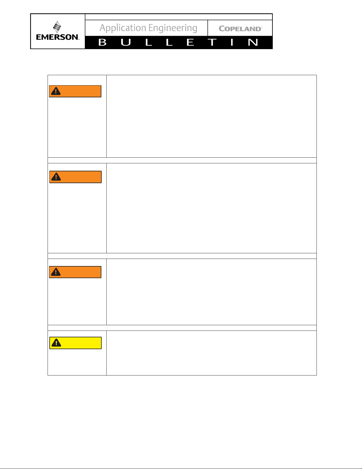
Instructions Pertaining to Risk of Electrical Shock, Fire, or Injury to Persons
ELECTRICAL SHOCK HAZARD
• Disconnect and lock out power before servicing.
• Discharge all capacitors before servicing.
• Use compressor with grounded system only.
• Molded electrical plug must be used when required.
• Refer to original equipment wiring diagrams.
• Electrical connections must be made by qualified electrical
personnel.
• Failure to follow these warnings could result in serious personal
injury.
PRESSURIZED SYSTEM HAZARD
• System contains refrigerant and oil under pressure.
• Remove refrigerant from both the high and low compressor side
before removing compressor.
• Never install a system and leave it unattended when it has no
charge, a holding charge, or with the service valves closed without
electrically locking out the system.
• Use only approved refrigerants and refrigeration oils.
• Personal safety equipment must be used.
• Failure to follow these warnings could result in serious personal
injury.
© 2021 Emerson Climate Technologies, Inc.
BURN HAZARD
• Do not touch the compressor until it has cooled down.
• Ensure that materials and wiring do not touch high temperature
areas of the compressor.
• Use caution when brazing system components.
• Personal safety equipment must be used.
• Failure to follow these warnings could result in serious personal
injury or property damage.
COMPRESSOR HANDLING
• Use the appropriate lifting devices to move compressors.
• Personal safety equipment must be used.
• Failure to follow these warnings could result in personal injury or
property damage.
Safety Statements
• Refrigerant compressors must be employed only for their intended use.
• Only qualified and authorized HVAC or refrigeration personnel are permitted to install commission and
maintain this equipment.
• Electrical connections must be made by qualified electrical personnel.
• All valid standards and codes for installing, servicing, and maintaining electrical and refrigeration equipment
must be observed.
Page 5

5
AE29-1439 R
1. Introduction
The XCM25D is a controller used on X-Line condensing
units which combine multiple capabilities such as:
• Condensing Unit Controls
• Condenser Fan Controls
• Defrost control
• CoreSense™ diagnostics and protection with
alarming and on-board error data logging
• Demand Cooling™ compressor temperature
protection
• XFAM / XFAP Models – Suction line liquid
injection
• XFAL Models – (3/4 – 1¼ HP) – Direct liquid
injection
• XFAL Models – (2 – 6 HP) Enhanced Vapor
Injection (EVI)
• Voltage, Current and Phase monitoring.
The XCM25D can be interconnected with the E2, E3
and Site Supervisor to be integrated to a much greater
network in a Retail Solution.
The Scope of this Bulletin is to bring information related
to the E2, E3 and Site Supervisor configuration settings
to communicate with XCM25D (X-Line) Condensing
Units.
Stores/Small-Box Retails Solutions. Additional models
were added in the Supervisor family namely the SR
(Service Replacement) and SA (Site Aggregator).
Every Family Series consists of different models with
lower to higher capacities. A summary for both the E2
capabilities are depicted in Table 1.
For a complete detail of every Model Capability, please
refer to the QR codes shown on Error! Reference source
not found. or simply click on the codes.
Figure 1 - XCM25D
Figure 1 shows the XCM25D controller.
2. E2 Controller
The E2 controllers are microprocessor-based
controllers providing complete control of compressor
groups, condensers, refrigerated cases, and other
components related to refrigeration and building control.
These are the controlling components of network
configurations – RS485 I/O, Echelon® Lon-Works™
Networks (E2 only), MODBus, BACNet and Ethernet.
What’s included are input and output boards, remote
communication software, and a variety of sensors,
probes, and transducers. Figure 2 to 4 shows the
Supervisory controller hardware.
2.1. E2 Controller Family Models and Capabilities
The controllers come in different family models: RX, BX
and CX. The RX family is for Refrigeration Systems
Control, BX is HVAC Systems Control and CX is HVAC,
Lighting and Refrigeration Systems for Convenience
Figure 2 - E2 Enhanced Controller
Figure 3 - E2 Controller Manual Link
© 2021 Emerson Climate Technologies, Inc.
Page 6

6
AE29-1439 R
Table 1 - E2 Family Description
Single refrigeration
system
One Condenser and up to
Four suction groups
Single refrigeration
system
One Condenser and up to
Four suction groups
Two separate
refrigeration systems
Two condensers and up to
four suction groups
BX-300
Up to 6 AHUs2
BX-400
Up to 8 AHUs
CX-1003
Up to 4 AHUs
CX-300
Up to 6 AHUs
Standard Mount:
9.06” W x 12.06” H x 3.75” D
Recessed Mount:
9.06” W x 10.56” H x 2.0” D
Base:
10.56” W x 10.56” H x 3.75” D
Operating Temp.
-40°F to 149°F (-40°C to 65°C)
Storage Temp
-40°F to 158°F (-40°C to 70°C)
Operating
Humidity
5% - 95% RH non-condensing at
90°F
Storage Humidity
5% - 100% RH
24 VAC ±20%, 50/60 Hz,
Class 2
VA Load
50
E2 Family Models Models Capabilities
1
RX-100
E2 RX Refrigeration
E2 BX HVAC systems
HVAC, Lighting, and
refrigeration systems for
E2 CX
Convenience Stores and
Small-Box Retail
Facilities
RX-300
RX-400
CX-400 Up to 8 AHUs
Table 2 - E2 Specifications
Dimensions
Figure 4 - E2 Front Panel
2.2. Software Licensing
Some applications are available only when activated
with a unique license key that is obtained through
Emerson software.
Call your Emerson Sales Representative at 770-4252724 for more information about software licensing.
1
Low-cost alternative RX-300 with fewer capabilities and a monochrome Display.
2
Air Handling units: AHUs
3
Low-cost alternative to CX-300 with fewer capabilities and a monochrome Display
© 2021 Emerson Climate Technologies, Inc.
Power
RX- and CX-100 versions support monochrome display
only.
2.3. XCM25D Network Setup on Supervisory Controllers
The XCM25D can be monitored by a Supervisory
controller which will receive alarms and notice statuses
from the X-line unit. Currently, the E2, E3 and Site
Supervisor are the controllers available from Emerson
Page 7
7
AE29-1439 R
capable of monitoring storewide controls and can help
with maintenance and system troubleshooting.
2.3.1. Adding the XCM25D to the E2 Controller
The XCM25D can be added to the E2 but it requires a
license key and a description file. Contact Emerson
technical support for the description file (.dsc), save the
.dsc file in your computer and take note of the license
key, to add instances of XMC25D. Below is the
information you need to provide to Emerson technical
support to generate the license key:
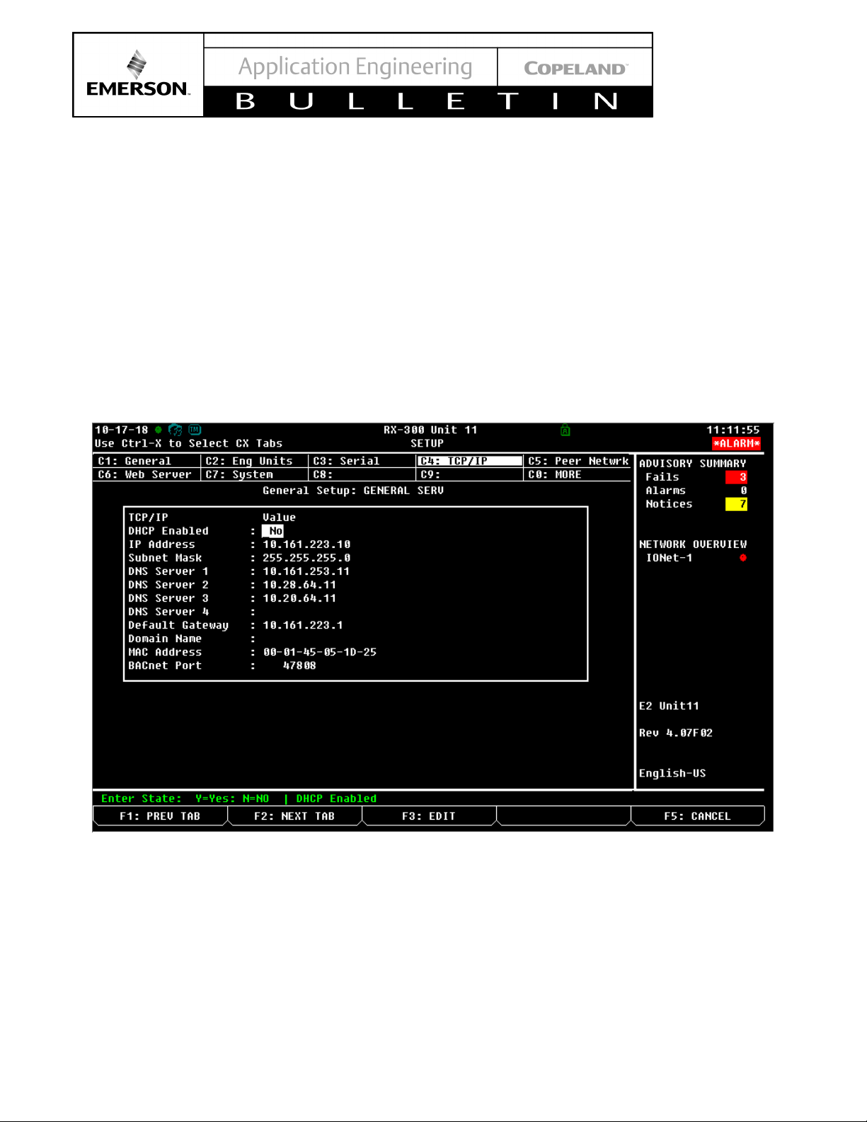
Press Menu>7>3>1 then Press F2: Next tab and go to
the TCP/IP tab, For the information listed below.
• E2 MAC Address
• E2 Model (Example: RX400), It is found on the top
middle portion of the screen
• Number of instances of XCM25D needed
• Description of purpose including for what site/store
Once you have secured the description file and license
key, you will need to connect your computer to the E2.
You must set the Internet protocol (TCP/IP) of PC to
static IP.
© 2021 Emerson Climate Technologies, Inc.
Figure 5 - E2 Screen with needed information for Emerson Technical Support
Page 8

8
AE29-1439 R
2.4. PC configuration for direct connection to E2
1. Open your PC, Press “Start” and go to “Control Panel” then click Network and Sharing Center. See figure below.
Figure 5 - PC Control Panel
2. Click Change adapter settings. See figure below.
© 2021 Emerson Climate Technologies, Inc.
Figure 6 - PC Network and Sharing Center Screen
Page 9
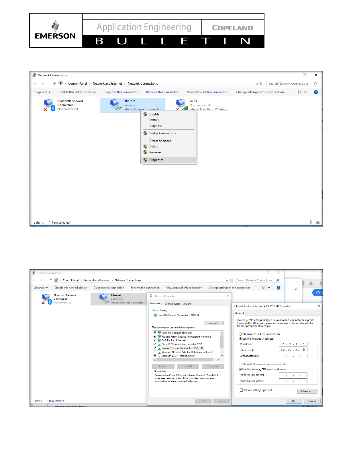
9
AE29-1439 R
3. Right click on Ethernet, then click Properties below.
Figure 7 - Ethernet options Submenu
4. Click Internet Protocol Version 4 (TCP/IPv4) > Click Properties > Put a tick mark on Use the following IP address
> Put the IP address to match the E2 IP address except for the last number, change this to a value slightly
different to what is set on the E2, also set corresponding subnet mask, same as what on E2. > Click OK. See
Figure below.
© 2021 Emerson Climate Technologies, Inc.
Figure 8 - Network Configuration Screen
Page 10

10
AE29-1439 R
2.5. Upload the Description file via UltraSite
Part Number
Description
File
5270744.dsc
Use the below description file if the XCM25D is not a native application on E2.
527-0744
XCM25D v1.3
For XFAM/XFAL units.
Download Configuration Files attached to this document.
1. Launch UltraSite (Contact Tech Support for UltraSite Software)
2. Login on UltraSite. By default, the Login access is USER/PASS
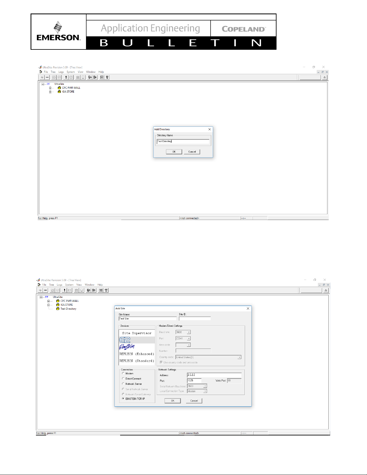
3. Under tree view, Right click on UltraSite > click “Add Directory”
4. Specify the directory name > click OK. See figure below.
© 2021 Emerson Climate Technologies, Inc.
Figure 9 - UltraSite Login Screen
Page 11
11
AE29-1439 R
Figure 10 - UltraSite Directory Name Screen
5. Right click on the newly created directory (Yellow house) > click “Add Site”
6. Specify the Site name
7. Under Devices, Click E2
8. Under Connection, Click Einstein TCP/IP
9. Under Network settings, specify the IP address of the E2 controller.
© 2021 Emerson Climate Technologies, Inc.
Figure 11 - E2 Address entering to UltraSite
Page 12

12
AE29-1439 R
10. Expand the Yellow house (Specific Directory) > right click on the Site > click Connect
Figure 12 - UltraSite Connection command
11. Expand the site by clicking the “+” icon on the blue house > Right click on the E2 controller on which the XCM is
connected > Click Upload Description file
© 2021 Emerson Climate Technologies, Inc.
Figure 13 - Uploading Description file to E2
Page 13

13
AE29-1439 R
Click Browse > Locate the description file that you saved from Tech support then Click Open> Click Upload >
Click Close > Manually reboot the E2
Figure 14 - Uploading 5270573.dsc file to E2
The description file is now added to the E2. Now you can add the XCM25D to the E2 controller
2.6. Final XCM25D integration into E2 Controller
1. After the reboot log in on the E2 controller by pressing the Login button.
© 2021 Emerson Climate Technologies, Inc.
Figure 15 - E2 Login Screen
Page 14

14
AE29-1439 R
2. From the Home Screen, Press Menu > 7 > 9 (Licensing), Press F1: Add feature, manually type the license
key received from Tech support. Wait for confirmation.
Figure 16 - E2 Add License Screen
3. From the Home Screen, Press Menu > 7 > 7 > 2, Press F2 to access Third Party devices. Specify the quantity
of the X-line units that you are commissioning and then press the staircase button to save the changes.
© 2021 Emerson Climate Technologies, Inc.
Figure 17 – E2 Add Devices Screen
Page 15

15
AE29-1439 R
2.7. Setup the COM Port for MODBUS.
1. Press Menu > 7 > 3 > 1, Press F2 to access Serial tab. Set one of the available COM ports except for Com1 and
Com3 to MODBUS via the F4: Look Up button. Set the configuration to the following:
Baud: 9600 baud
Data Size: 8
Parity: None
Stop Bits: 1
2.8. Network Wiring
XCM25D is connected on the E2 through the MODBUS
communication protocol.
Make sure to configure the port settings on the E2 that
is being used for the XCM25D, refer to the E2 manual
for steps to configure communication ports, or the
previously mentioned instructions.
The XCM is daisy chained to the E2 using shielded
twisted pair wiring. Belden cable is recommended. Refer
to Figure 19 for polarity at the connector wiring.
2.9. Communication Setup – XCM25D
1. The XCM25D controller will be able to communicate
© 2021 Emerson Climate Technologies, Inc.
Figure 18 - Modbus Configuration in E2 for X-line connection
with the E2 Modbus RTU Slave RS485 slave
protocol. The XCM25D Modbus parameters will be
configurable via the quick access menu or the
Wizmate software and the communication
parameters will be as follows:
Adr/T01: (x) Configurable
Baud rate: 9600
Byte length: 8
Stop bits: 1
Parity: None
Baud Rate, Byte length, Stop bits and Parity must
match the E2 configuration the XCM25D Modbus
address Adr/T01 must be the same as what is
configured/commissioned on E2. Network
Summary Screen. Note that the default setting in the
XCM25D is address 1, This may need to be
changed during commissioning.
Example: XCM25D Adr/T01 = 6 with the
corresponding X-LINE Modbus Address = 6 also.
(Refer to Section 2.7: Setup the COM Port for
MODBUS.)
2. Commission the XCM25D by accessing the E2
Network Summary screen set up, Press Menu > 7 >
7 > 1, Scroll down the devices then highlight the
recently added X-Line, Press F4 for Commission,
Specify the network address then press Enter twice.
See Figure 20.
Note: Make sure the Network address is same as
the Adr/T01 parameter on the XCM.
3. Wait for a few seconds until the X-Line shows
“Online”. See Figure 21
Page 16

16
AE29-1439 R
Figure 19 - XCM25D Modbus connection with E2
Figure 20 - X-line Unit Address Inclusion Screen
© 2021 Emerson Climate Technologies, Inc.
Page 17

17
AE29-1439 R
Figure 21 - X-line Unit Integration Confirmation Screen
2.10. Send Device Configuration to E2
The configured XCM25D parameters now need to be sent up to the E2.
To manually send the XCM configuration to E2. Go to the Status Screen of XCM, Press Enter > 9. Applications
Commands > 2. Send Device Cfg to E2 > Enter
You should now be able to view the correct device information on the status screen.
© 2021 Emerson Climate Technologies, Inc.
Figure 22 - Device Configuration sending to E2
Page 18

18
AE29-1439 R
Operating Temperature
-40°F to 149°F
Relative Humidity
20-85% RH
Enclosure Rating
UL 94 V-0
Dimensions
110mm x 183mm
Power In
24VAC 50/60 Hz +/- 10% 20VA
1 Can Bus
Expansion Module Connections
4 RS485 ports
MODBUS Com Ports 1, 2, 3,
3 Ethernet ports
Ports 1, 1, 0
Analog Inputs
8
MicroSD
1
Digital Inputs
4
Relay Outputs
4
Agency Approvals
Operating Temperature
-40°F to 149°F (-40°C to
65°C)
Operating Humidity
5% - 95% RH noncondensing at 90°F
Storage Humidity
5% - 100% RH
Power Supply
24 VAC ±20%, 50/60 Hz,
Class 2
Dimensions
12” L x 12.5” W x 3.75 H”
RS485 Ports
COMM 1 = RS485 Com 2 A
and B
Ethernet Ports
Ports 0,1
USB Ports
J2, J3
3. E3 / Site Supervisor
Figure 23 - Site Supervisor
2 USB Ports 1, 2
Table 4 - E3 Specifications
Only
and 4
ULE211299, CE
Figure 24 - E3 Controller
The Site Supervisor and E3 are systems that combine
energy management with the ability to monitor various
facility systems and provide alerts when there are issues
that need attention. These systems provide HVAC
control, Refrigeration System Monitoring and Control,
as well as Lighting Control. In addition, these controllers
can monitor and report energy consumption.
Table 3 - Site Supervisor Specifications
(-40°C to 65°C)
non-condensing
5/16
” x 7
3/16
”)
(4
24VDC +/- 10% .8A
and B
COMM 2 = RS485 Com 6
(isolated)
COMM 3 = RS485 Com 7
(isolated)
COMM 4 = RS485 Com 4 A
3.1. Housing Dimensions and Mounting
The Site Supervisor can be mounted to standard 35mm
DIN rail using the orange mountain clips. It can also be
screwed to a back plate by pulling the four (4) orange
mounting tabs out until they lock which will expose
mounting holes. See for Figure 25 detailed dimensions.
The E3 controller however is recessed mounted on
panels with the detailed hardware dimensions indicated
on Figure 28.
© 2021 Emerson Climate Technologies, Inc.
Page 19

19
AE29-1439 R
Figure 25 - Site Supervisor Dimensions
Figure 27 - Site Supervisor Manual QR Code
Figure 26 - Site Supervisor Detail
© 2021 Emerson Climate Technologies, Inc.
Figure 28 - E3 Dimensions
Page 20

20
AE29-1439 R
Table 5 - E3 / Supervisor Family Descriptions
Small Format
Retailers
Up to 4 AHUs; 6 Standard
Circuits
Single refrigeration
system
One Condenser and up to
Four suction groups
Two separate
refrigeration systems
Two condensers and up to
four suction groups
BXs
Up to 6 AHUs4
BXe
Up to 8 AHUs
HVAC, Lighting, and
Facilities
CXs
Up to 6 AHUs
SR
Service Replacement
SR
Max number of applications, All 400 Model level
Enable aggregating of data and device status all in one
screen
Supervisor Family Models Models Capabilities
SMF Small Format SMF
RXs
RX Refrigeration
RXe
BX HVAC systems
refrigeration systems for
CX
Convenience Stores and
Small-Box Retail
CXe Up to 8 AHUs
SA Site Aggregator SA
3.2. E3 / Site Supervisor Power, Serial, and IO Positions
Figure 29 - Site Supervisor Power, Serial, and IO Positions
4
Air Handling units: AHUs
© 2021 Emerson Climate Technologies, Inc.
Page 21

21
AE29-1439 R
Figure 30 - E3 Power, Serial, and IO Positions
3.2.1. Site Supervisor Termination Jumpers
The termination and biasing dip switches are located to the left of their respective communications port connectors.
Depending on the orientation of the board, the termination jumpers are set in the down position (always toward the
board - ON) for termination and up (always away from the board - OFF) for no termination.
Position 1 = Termination
Position 2 = Bias.
Figure 31 - Termination Jumpers position
Biasing
The transmission line into the RS-485 serial port enters an indeterminate state when it is not being transmitted to.
This indeterminate state can cause the receivers to receive invalid data bits from the noise picked up on the cable.
To prevent this, set the bias dip switch to ON (down) which will add the appropriate amount of resistance.
3.3. XCM25D Network Setup on the E3 / Site Supervisor
XCM25D can be monitored by the E3 / Supervisor which will receive alarms and notice statuses from the X-line unit.
Monitoring can deliver greater energy and maintenance savings than any other initiatives.
© 2021 Emerson Climate Technologies, Inc.
Page 22

22
AE29-1439 R
3.4. Network Wiring
XCM25D is connected to the E3 / Supervisor through MODBUS communication protocol. One key difference in the
communication wiring of the XCM25D with the two supervisory controllers is that only with the Site Supervisor does
the XCM25D has the same MODBus polarity. The E3 will be connected to the XCM25D with reverse polarity.
3.5. Communication Setup – XCM25D
The controller will be able to communicate with a Modbus RTU Slave RS485 slave protocol. The Modbus address
will be configurable in the Adr/T01 parameters and the communication parameters will be:
Baud rate 9600
Byte length: 8,
Stop bits: 1;
No parity bit as the std requirements.
Communication parameters are fixed.
© 2021 Emerson Climate Technologies, Inc.
Figure 32 – Site Supervisor and X-Line Interconnection Diagram
Page 23

23
AE29-1439 R
Figure 33 - E3 and X-Line Interconnection Diagram
E3 to XCM25D
3.6. Communication Setup – E3 / Supervisor
SHOULD BE WIRED
VIA RS485 MODBUS –
REVERSE POLARITY
3.6.1. Setup the COM Port for MODBUS.
1. Log-in. Use “USER” for username and “PASS” for password.
Figure 34 - User and Password Screen in E3 / Supervisor
2. Click the Menu Icon > Configure System > General System Properties > COM Ports. Use any of the 4 COM
ports for MODBUS with the below communication setup.
© 2021 Emerson Climate Technologies, Inc.
Page 24

24
AE29-1439 R
Figure 35 - ModBus Connections Settings
3.6.2. Adding the XCM25D in the E3 / Supervisor program
The Supervisor needs to have a firmware version of not later than 2.05F01. On this firmware, the XCM25D is nonnative but can be added. Contact Emerson Technical Support for the ADF file and license key to add instances of
XMC25D. Below is the information you need to provide to generate a license key:
• E3 / Supervisor MAC Address
• E3 / Supervisor Model (Example: SMF)
Once you secured a license key, below is how you can add it in the E3 / Supervisor.
1. Log-in. Use “USER” for username and “PASS” for password.
• Model/Version of XCM25D (Ex. XCM25D v.1.3
XFAL)
• Number of instances of XCM25D
2. Click on the Menu icon > Configure System > File Management & Licensing. Then click the “Install ADF file”
© 2021 Emerson Climate Technologies, Inc.
Figure 36 – E3 / Site Supervisor Log In Screen
button. Select the file and click “Install”.
Page 25

25
AE29-1439 R
Figure 37 - ADF File selection Screen
3. After confirming the installation of the ADF file, the E3 / Supervisor will reboot. Once back up, log-in once again
and go back to the File Management & Licensing. Click Install License and enter the license key provided by
technical support. Click “Go” to proceed.
© 2021 Emerson Climate Technologies, Inc.
Figure 38 – Enter License Screen
Page 26

26
AE29-1439 R
4. Click on the Control Inventory icon and under the Refrigeration tab click the “Add Control” and select the
XCM25D.
Figure 39 - XCM25D Selection Screen
5. Set the Name of the application. On port ID, select the Modbus you set previously. On the Address, set the
address you put on Adr/T01 parameter of XCM25D.
Figure 40 - XCM25D Address Entry Screen
6. When wiring and communication setup are correct, the device should appear online as shown on Figure 40.
© 2021 Emerson Climate Technologies, Inc.
Page 27

27
AE29-1439 R
Figure 41 – Control Inventory Screen
3.6.3. Sending the Device Configuration to the E3 / Supervisor
1. Once the device is online, click on the application name to open the application setup page.
Figure 42 - Application Setup Page
© 2021 Emerson Climate Technologies, Inc.
Page 28

28
AE29-1439 R
Part Number
Description
Version
File
531-0105.adf
531-0136.adf
2. Click on the icon located on the tope right corner of the screen. Select the “Read Configuration from Device”.
A confirmation message should appear when the read is successful.
Figure 43 - Read Configuration Screen
3.7. Integration File
Use the below ADF if the XCM25D is not a native application on Supervisor.
531-0105
531-0136
XCM25D_13_FAL
XCM25D_13_FAM
1.3
1.3
Download Configuration Files attached to this document.
© 2021 Emerson Climate Technologies, Inc.
Page 29

29
AE29-1439 R
Maximum voltage
and current that can
be applied to the
humidity, special
Electrical safety
Maximum current to
4. XWEB EVO
Figure 44 - XWEB EVO
XWEB represents one of the most advanced monitoring,
control and supervision systems available on the market
today. The user will benefit from a power device, which
is easy to use and highly customizable for all
requirements. It uses the most advanced technology for
displaying the web pages and is based on the Linux™
operating system which guarantees its efficiency and
reliability. The hardware is based on highly reliable
industrial boards that require practically no maintenance
whatsoever.
4.1. XCM25D Network Setup on XWEB EVO
XCM25D can be monitored by a XWEB EVO which will
receive alarms and notice statuses from the X-line unit.
Monitoring can deliver greater energy and maintenance
savings than any other initiatives.
4.2. Network Wiring
XCM25D is connected on the WEB EVO through
MODBUS communication protocol.
4.3. Communication Setup – XCM25D
The controller will be able to communicate with a
Modbus RTU Slave RS485 slave protocol. The Modbus
address will be configurable in the Adr/T01 parameters
and the communication parameters will be:
Baud rate 9600
Byte length: 8,
Stop bits: 1;
No parity bit as the std requirements.
Communication parameters are fixed.
Table 6 - XWEB EVO Specifications
Power supply 24V or 100-230V (DIN
models)
230V (“COOLMATE”
models)
Power 15VA Max (DIN models)
20VA Max (“COOLMATE”
models)
24V
AUX1-2-3 terminals
Operating conditions
(temperature,
conditions)
(reference
standards)
Electromagnetic
compatibility
(reference
standards)
the USB device
T: 10-60°C R.H.20-85%
(non-condensing) (DIN
models) T: 0-60°C, R.H. 20-
85% (non-condensing)
(“COOLMATE” models)
Standard EN 60950-1
Immunity
EN 61000-6-2:2005
EN 55024:1998 + /A1:2001
+/A2:2003
EN 61000-4-2:2009
EN61000-4-3:2006
+/A1:2008
EN61000-4-4:2004
EN 61000-4-5:2006
EN 61000-4-6:2009
EN 61000 -4 -8:1993 +/
A1:2001
EN 61000-4-11:2004
Emissions
EN 55022:2006+/A1:2007
EN 61000-3-2:2006
+/A1:2009 +/A2:2009
EN 61000-3-3 :2008
200
© 2021 Emerson Climate Technologies, Inc.
Page 30

30
AE29-1439 R
Figure 45 – XWEB EVO and X-Line Interconnection Diagram
4.4. Communication Setup – XWEB EVO
1. Open your Internet Browser and type the XWEB EVO’s IP Address to Log-in. Use “Admin” for
username and “Admin” for password.
© 2021 Emerson Climate Technologies, Inc.
Figure 46 – XWEB EVO Log In Screen
Page 31

31
AE29-1439 R
2. Make sure acquisitions are off by clicking on the Acquisition Button then Confirm.
Figure 47 – Stopping Acquisitions
3. Expand the System tab and select Update
4. Click Update button and select Upload. Locate the zip file on your drive
© 2021 Emerson Climate Technologies, Inc.
Figure 48 – XWEB EVO Home Screen
Page 32

32
AE29-1439 R
Figure 49 – XWEB EVO Library Upload
5. Click Update
6. Expand the Devices tab and select Settings
© 2021 Emerson Climate Technologies, Inc.
Figure 50 – XWEB EVO Library Update
Page 33

33
AE29-1439 R
Figure 51 – XWEB EVO Devices Menu
7. Click the + button to add a new device.
© 2021 Emerson Climate Technologies, Inc.
Figure 52 – Adding a new device
Page 34

34
AE29-1439 R
8. Set the Source to Library and look for the device to be added under the Library
Figure 53 – Adding via XWEB Library
9. Use these settings for the Protocol and the Peripheral:
Protocol: Modbus 485 (dixell485)
Peripheral: RS485 1 (RS1)
Add the Modbus address and the Quantity required. Click Add when done.
© 2021 Emerson Climate Technologies, Inc.
Figure 50 – XWEB EVO Modbus Setup
Page 35

35
AE29-1439 R
6.5. XWEB Library
Market
Description
Version
File
XCM25D_0045000D0006. zip
XCM25D_0045000D0007. zip
P/N
Title
E2 Installation and Operation Manual for
Refrigeration, BX HVAC, and CX
Convenience Store Controllers
Site Supervisor Controller 2.08 User
Guide
Emerson Product Technical Sheet
Binder
The contents of this publication are presented for informational purposes only and are not to be construed as warranties or guarantees, express or implied,
remains solely with the purchaser or end user.
Use the below Library if the XCM25D is not a native application on XWEB EVO.
Asia XCM25D 1.3
America XCM25D_13_FAM 1.3
Download Configuration Files attached to this document.
10. General Guidelines and More Information
For general E2, Site Supervisor and XWEB EVO
information please visit Emerson.com/OPI
your Application Engineer.
Emerson publications listed below can be ordered on
their printed version by contacting Emerson:
026-1614
RX
026-1800
026-1904
or contact
regarding the products or services described herein or their use or applicability. Emerson Climate Technologies, Inc. and/or its affiliates (collectively
"Emerson"), as applicable, reserve the right to modify the design or specifications of such products at any time without notice. Emerson does not assume
responsibility for the selection, use or maintenance of any product. Responsibility for proper selection, use and maintenance of any Emerson product
© 2021 Emerson Climate Technologies, Inc.
 Loading...