

Page 1
764-700 to 764-759
WHITE-RODGERS
Operator: Save these instructions for future use!
FAILURE TO READ AND FOLLOW ALL INSTRUCTIONS CAREFULLY
BEFORE INSTALLING OR OPERATING THIS CONTROL COULD CAUSE
PERSONAL INJURY AND/OR PROPERTY DAMAGE.
Ideal for use on wall heaters, space heaters, consoles,
etc., this gas pilot safety valve provides 100% shut-off of
both pilot and main burner gas supply in the event of pilot
flame failure. This valve is equipped with a 3-position gas
control knob to provide for pilot lighting. This control also
allows pilot flame adjustment.
If the pilot flame goes out during normal operation, or if
there is insufficient pilot flame to provide proper thermocouple output, the safety valve will close, stopping the
flow of all gas. This valve is designed for use on all
domestic heating gases up to 1⁄2” PSI.
Dual Inlet Gas Pilot Safety Valve
(Thermocouple-Operated)
INSTALLATION INSTRUCTIONS
DESCRIPTION
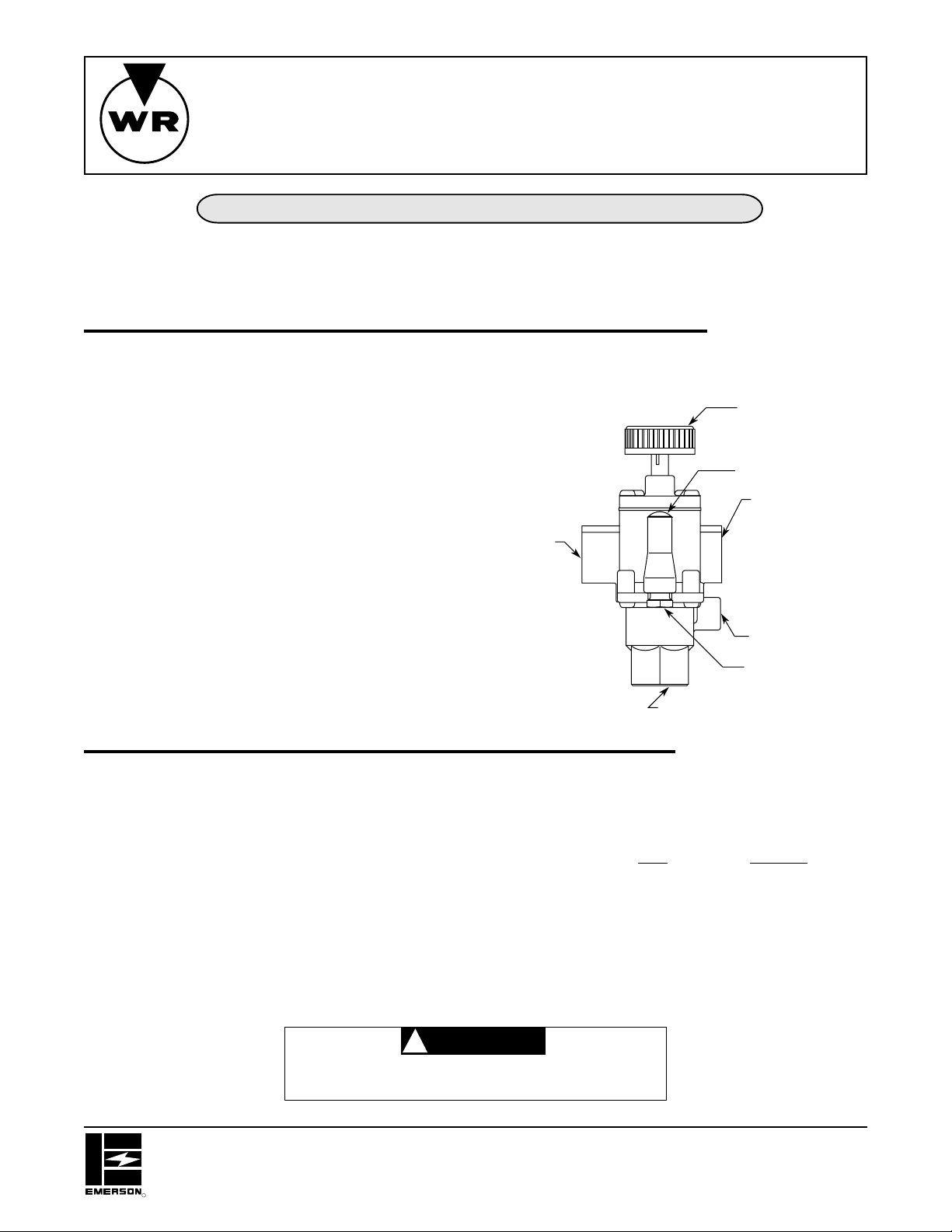
DUAL INLET
(NOTE: One inlet to be plugged)
Gas control
knob
Pilot adjust
cover screw
Outlet
Inlet
Capacity (for AGA natural gas at 1” drop):
3
⁄8” x 3⁄8” size:
side inlet – 112,000 BTU/hr.
bottom inlet – 107,000 BTU/hr.
1
⁄2” x 1⁄2” size:
side inlet – 124,000 BTU/hr.
bottom inlet – 118,000 BTU/hr.
Pilot connection: 1⁄4” tubing
Pressure:1⁄2” PSI maximum
Ambient Rating: -40°F to 250°F operating temperature
Mounting Position: Multipoise
CAUTION
!
DO NOT USE THESE GAS VALVES WITH
UNVENTED APPLICATIONS.
Thermocouple
connection
Pilot gas
tapping
Inlet
SPECIFICATIONS
Ignition Source: Pilot
Type of gas: Suitable for all domestic heating gases
Thermocouple: Use W.R. Type H06E
Accessories: Item Part No.
Replacement Knob F42-0895
Stem Extender F145-1111
Approvals: ANSI Z21.78 Combination Gas Control
CAN 1-6.4
CAN 1-9.1
WHITE-RODGERS DIVISION
EMERSON ELECTRIC CO.
9797 REAVIS ROAD
ST. LOUIS, MISSOURI 63123-5398
R
Printed in U.S.A.
PART NO. 37-5234E
Replaces 37-5234D
9502
Page 2
INSTALLATION
These gas valves should be installed according to the
following instructions. Check for gas leaks with a soap
solution after completing installation.
CAUTION
!
Never use flame to detect leaks.
CAUTION
!
Do not leave unused inlet unplugged.
CAUTION
!
DO NOT USE THESE GAS VALVES WITH
UNVENTED APPLICATIONS.
MAIN PIPING CONNECTIONS
1. Be sure the main gas supply is shut off before starting
the installation. The gas valve may be installed in any
position, but it should be located so that the gas
control knob is easily accessible.
2. Direction of gas flow is indicated by the directional
arrow on the outlet boss.
3. You should use new pipe, which has been properly
chamfered and reamed. If you use old pipe, be sure
it is clean and free of rust, scale, burrs, chips and old
pipe joint compound.
4. If the side inlet is to be used, it is necessary to remove
the plug and install it in the bottom inlet. This procedure requires a 5⁄16” Allen wrench. Be sure the end of
the plug is free of burrs, chips, etc. Before installing
plug, apply pipe joint compound (pipe dope) that is
approved for all gases, only to the male threads of the
plug. DO NOT apply compound to first two threads.
Do not overtighten the plug.
5. Apply pipe joint compound (pipe dope) that is approved for all gases, only to the male threads of pipe
joints. DO NOT apply compound to first two threads.
Do not thread pipe too far.
NOTE
Applying pipe joint compound to pipe threads will prevent
chips from passing onto internal valve parts, since the
pipe joint compound will collect and retain chips that are
formed as the pipe is threaded into the body.
6. If a vise or open-end wrench is used to hold the control
while installing piping, do not tighten excessively, as
this may damage the control.
PILOT GAS CONNECTION
Install the fitting into the pilot gas tapping, turning until
finger-tight. Insert clean, deburred tubing all the way
through the fitting. Holding the tubing securely, slowly
tighten the fitting until a slight “give” is felt. Then tighten an
additional 11⁄2 turns.
THERMOCOUPLE
The thermocouple connector should be clean for good
electrical contact. Run the thermocouple nut into the
thermocouple connection as far as possible by hand.
Then set the nut with 1⁄4 to 1⁄2 additional turn using a small
wrench. Do not overtighten.
2
Page 3
FOR YOUR SAFETY READ BEFORE LIGHTING
!
WARNING
A. This appliance has a pilot which must be lighted by hand.
When lighting the pilot, follow these instructions exactly.
B. BEFORE LIGHTING smell all around the appliance area for
gas. Be sure to smell next to the floor because some gas is
heavier than air and will settle on the floor.
FOR YOUR SAFETY
“WHAT TO DO IF YOU SMELL GAS”
• Do not try to light any appliance.
• Do not touch any electrical switch; do not use any
phone in your building.
• Immediately call your gas supplier from a neighbor's
If you do not follow these instructions exactly, a fire or explosion
may result causing property damage, personal injury or loss of life.
PILOT LIGHTING PROCEDURE
1. Turn the gas control knob to the OFF position (it will
be necessary to depress the knob slightly at the
PILOT position). Allow five minutes for any gas in the
combustion chamber to escape (LP gas, which is
heavier than air, may require forced ventilation).
2. Turn the gas control knob to the PILOT position.
3. Push down on the gas control knob and light the pilot
immediately. Hold the knob down for one full minute
after lighting the pilot.
4. When the gas control knob is released, the pilot flame
should continue to burn (if the pilot goes out, repeat
the above steps).
5. Rotate the gas control knob from PILOT to ON
position (full counterclockwise position) to
supply full flow to main burner.
NOTE
phone. Follow the gas supplier's instructions.
• If you cannot reach your gas supplier, call the fire
department.
C. Use only your hand to push in or turn the gas control knob.
Never use tools. If the knob will not push in or turn by hand,
don't try to repair it, call a qualified service technician. Force
or attempted repair may result in a fire or explosion.
D. Do not use this appliance if any part has been under water.
Immediately call a qualified service technician to inspect the
appliance and to replace any part of the control system and
any gas control which has been under water.
PILOT FLAME ADJUSTMENT
These controls are factory preset and will not normally
require additional adjustment of the pilot flame. If field
adjustment of the pilot flame is required, remove the pilot
adjust cover screw to expose the adjusting screw. Turn
the adjusting screw clockwise ( ) to reduce flame,
or counterclockwise ( ) to increase flame. Re-
place pilot adjust cover screw and tighten securely.
TESTING
After completing the installation, check for proper operation by turning the gas control knob to the PILOT position.
With the pilot lit, loosen the thermocouple connection. The
pilot should immediately go out. Turn the gas control knob
to the OFF position and retighten the thermocouple connection.
Not turning the gas control knob to the full ON position will
reduce the flow and could result in poor ignition of main
burner.
Allow five minutes before relighting the pilot.
3
Page 4

If you need further information about this product, please write to:
White-Rodgers Division, Emerson Electric Co.
9797 Reavis Road
St. Louis, MO 63123-5398
Atttention: Technical Service Department
 Loading...