

Page 1

Spec. Nos. 586505000 and 5865055000 (Model LMS1000)
Issue AL, July 24, 2006
MONITORING SYSTEM
SPEC. NOS.: 586505000
586505500
MODEL: LMS1000
Section 5847
User Instructions
User Instructions
Firmware Version 6.3
This document is property of Emerson Network Power, Energy Systems, North America, Inc. and contains confidential and proprietary information owned by Emerson Network Power, Energy
Systems, North America, Inc. Any copying, use, or disclosure of it without the written permission of Emerson Network Power, Energy Systems, North America, Inc. is strictly prohibited.
Page 2

Section 5847 User Instructions
Issue AL, July 24, 2006 Spec. Nos. 586505000 and 5865055000 (Model LMS1000)
The Emerson logo is a trademark and
service mark of Emerson Electric Co.
Lorain® is a registered trademark of Emerson
Network Power, Energy Systems, North America, Inc.
Vortex® is a registered trademark of Emerson
Network Power, Energy Systems, North America, Inc.
The products covered by this instruction manual are manufactured and/or
sold by Emerson Network Power, Energy Systems, North America, Inc.
If we can be of any further assistance to you,
please call one of our sales representatives
at (440) 288-1122.
For parts, service, depot repair, technical assistance, or training, call toll free:
one of the numbers listed on the Service Information Sheet (Section 4154).
Copyright © 2006, Emerson Network Power, Energy Systems, North America, Inc.
This document is property of Emerson Network Power, Energy Systems, North America, Inc. and contains confidential and proprietary information owned by Emerson Network Power, Energy
Systems, North America, Inc. Any copying, use, or disclosure of it without the written permission of Emerson Network Power, Energy Systems, North America, Inc. is strictly prohibited.
Page 3

User Instructions Section 5847
Spec. Nos. 586505000 and 5865055000 (Model LMS1000) Issue AL, July 24, 2006
STATIC WARNING
The printed circuit cards used in this equipment contain static sensitive components. The warnings listed below
must be observed to prevent damage to these components. Disregarding any of these warnings may result in
personal injury or damage to the equipment.
1. Do not insert or remove printed circuit cards with power applied. Wait at least 5 minutes after power is
turned off (or until power supplies have discharged to zero volts) before removing any circuit card.
2. Before touching any static sensitive component or printed circuit card containing such a component,
discharge all static electricity from yourself by wearing a wrist strap grounded through a one megohm
resistor. Some wrist straps, such as Emerson Network Power P/N 631810600, have a built-in one
megohm resistor; no external resistor is necessary. Read and follow wrist strap manufacturer’s
instructions outlining use of a specific wrist strap.
3. Do not touch the traces or components on a printed circuit card containing static sensitive components.
Handle the printed circuit card only by the edges that do not have connector pads.
4. After removing a printed circuit card containing a static sensitive component, place the printed circuit card
only on conductive or anti-static material such as conductive foam, conductive plastic, or aluminum foil.
Do not use ordinary Styrofoam or ordinary plastic.
5. Store and ship static sensitive devices or printed circuit cards containing such components only in static
shielding containers.
6. If necessary to repair a printed circuit card containing a static sensitive component, wear an appropriately
grounded wrist strap, work on a conductive surface, use a grounded soldering iron, and use grounded
test equipment.
Static Warning Page 1 of 2
This document is property of Emerson Network Power, Energy Systems, North America, Inc. and contains confidential and proprietary information owned by Emerson Network Power, Energy
Systems, North America, Inc. Any copying, use, or disclosure of it without the written permission of Emerson Network Power, Energy Systems, North America, Inc. is strictly prohibited.
Page 4

Section 5847 User Instructions
Issue AL, July 24, 2006 Spec. Nos. 586505000 and 5865055000 (Model LMS1000)
This Page Left Intentionally Blank
Page 2 of 2 Static Warning
This document is property of Emerson Network Power, Energy Systems, North America, Inc. and contains confidential and proprietary information owned by Emerson Network Power, Energy
Systems, North America, Inc. Any copying, use, or disclosure of it without the written permission of Emerson Network Power, Energy Systems, North America, Inc. is strictly prohibited.
Page 5

User Instructions Section 5847
Spec. Nos. 586505000 and 5865055000 (Model LMS1000) Issue AL, July 24, 2006
FCC INFORMATION
The modem circuit card of LMS1000 (if installed) has been granted a registration number by the Federal
Communications Commission, under Part 68 rules and regulations for direct connection to the telephone lines. In
order to comply with these FCC rules, the following instructions must be carefully read and applicable portions
followed completely:
a) Direct connection to the telephone lines may be made only through the standard plug- ended cord
furnished to the utility-installed jack. No connection may be made to party or coin phone lines. Prior to
connecting the device to the telephone lines, you must:
b) Call your telephone company and inform them you have an FCC registered device you desire to connect
to their telephone lines. Give them the number(s) of the line(s) to be used, the make and model of the
device, the FCC registration number and ringer equivalence. This information will be found on the device
or enclosed with instructions as well as the jack suitable for your device.
c) After the telephone company has been advised of the above you may connect your device if the jack is
available, or after the telephone company has made the installation.
d) Repairs may be made only by the manufacturer or his authorized service agency. Unauthorized repairs
void registration and warranty. Contact seller or manufacturer for details of permissible user performed
routine repairs, and where and how to have other than routine repairs.
e) If, through abnormal circumstances, harm to the telephone lines is caused, it should be unplugged until it
can be determined if your device or the telephone line is the source. If your device is the source, it should
not be reconnected until necessary repairs are effected.
f) Should the telephone company notify you that your device is causing harm, the device should be
unplugged. The telephone company will, where practicable, notify you, that temporary discontinuance of
service may be required. However, where prior notice is not practicable, the telephone company may
temporarily discontinue service, if such action is reasonably necessary, in such cases the telephone
company must (A) Promptly notify you of such temporary discontinuance, (B) Afford you the opportunity
to correct the condition and (C) Inform you of your rights to bring a complaint to the FCC under their rules.
g) The telephone company may make changes in its communications facilities, equipment, operations or
procedures, where such action is reasonably required in the operation of its business and is not
inconsistent with FCC rules. If such changes can be reasonably expected to render any customer’s
devices incompatible with telephone company facilities, or require modification or alteration, or otherwise
materially affect its performance, written notification must be given to the user, to allow uninterrupted
service.
The following information is provided here and on a label attached to the outside of the system cabinet when
equipped with a modem circuit card.
MODEM JACK RINGER EQUIVALENCE FCC REGISTRATION NUMBER
56K bps RJ-11 0.2A B46USA-22429-MM-E
FCC Information Page 1 of 2
This document is property of Emerson Network Power, Energy Systems, North America, Inc. and contains confidential and proprietary information owned by Emerson Network Power, Energy
Systems, North America, Inc. Any copying, use, or disclosure of it without the written permission of Emerson Network Power, Energy Systems, North America, Inc. is strictly prohibited.
Page 6

Section 5847 User Instructions
Issue AL, July 24, 2006 Spec. Nos. 586505000 and 5865055000 (Model LMS1000)
This Page Left Intentionally Blank
Page 2 of 2 FCC Information
This document is property of Emerson Network Power, Energy Systems, North America, Inc. and contains confidential and proprietary information owned by Emerson Network Power, Energy
Systems, North America, Inc. Any copying, use, or disclosure of it without the written permission of Emerson Network Power, Energy Systems, North America, Inc. is strictly prohibited.
Page 7

User Instructions Section 5847
Spec. Nos. 586505000 and 5865055000 (Model LMS1000) Issue AL, July 24, 2006
TABLE OF CONTENTS
CONTENTS PAGE
CHAPTER 1 INTRODUCTION............................................................................................... 1-1
Table of Contents............................................................................................................................................. 1-1
Preface ............................................................................................................................................................. 1-1
What is LMS1000............................................................................................................................................. 1-1
LMS1000 Consists Of... ................................................................................................................................... 1-2
LMS1000 Provides .......................................................................................................................................... 1-3
CHAPTER 2 OPERATING LMS1000..................................................................................... 2-1
Table of Contents............................................................................................................................................. 2-1
LMS Description............................................................................................................................................... 2-3
Components of LMS.................................................................................................................................. 2-3
LMS Channel Numbering Scheme............................................................................................................ 2-3
Local Controls and Indicators .......................................................................................................................... 2-6
LMS Display Option................................................................................................................................... 2-6
Location and Identification......................................................................................................................... 2-6
LMS CPU Circuit Cards ............................................................................................................................. 2-6
Accessing the System through a Local or Remote Terminal........................................................................... 2-8
Passwords and Access Levels .................................................................................................................. 2-8
Terminal Requirements ............................................................................................................................. 2-8
Local Terminal Access .............................................................................................................................. 2-9
Remote Terminal Access .......................................................................................................................... 2-9
Using a Terminal........................................................................................................................................ 2-9
Logging On To the System...................................................................................................................... 2-11
Callback Feature...................................................................................................................................... 2-12
Header Information.................................................................................................................................. 2-12
Logging Off of the System ....................................................................................................................... 2-12
Accessing LMS1000 via TELNET and TFTP................................................................................................. 2-13
Accessing LMS1000 via SNMP (if SNMP Software Option is installed)........................................................ 2-13
Management Information Base (MIB) User Interface.............................................................................. 2-13
Using the TL1/X.25 Port (if TL1/X.25 Software Option is installed) ............................................................... 2-14
Using the TL1 Port (if TL1 [over Ethernet] Software Option is installed) ....................................................... 2-14
Using the Gateway Port (if Gateway Software Option is installed)................................................................ 2-15
Using Programmable Commands.................................................................................................................. 2-17
Using the Alarm Cutoff Feature ..................................................................................................................... 2-18
Forcing On Relays or LED's........................................................................................................................... 2-18
Acknowledging System Alarms...................................................................................................................... 2-19
Getting Analog and Function Channel Statistics .................................................................................
Using the Scan Feature ................................................................................................................................. 2-19
Using the Rate Feature (Analog Channel Maximum Load Percentages Report).......................................... 2-20
Viewing and Clearing the Alarm Log.............................................................................................................. 2-20
.......... 2-19
Table of Contents Page i
This document is property of Emerson Network Power, Energy Systems, North America, Inc. and contains confidential and proprietary information owned by Emerson Network Power, Energy
Systems, North America, Inc. Any copying, use, or disclosure of it without the written permission of Emerson Network Power, Energy Systems, North America, Inc. is strictly prohibited.
Page 8

Section 5847 User Instructions
Issue AL, July 24, 2006 Spec. Nos. 586505000 and 5865055000 (Model LMS1000)
Viewing and Clearing the Event Log.............................................................................................................. 2-22
Using Status Pages........................................................................................................................................ 2-27
Using Information Pages................................................................................................................................ 2-28
Using the Mail Service ................................................................................................................................... 2-28
Methods of Obtaining Specific Information .................................................................................................... 2-29
Downloading and Uploading the Configuration.............................................................................................. 2-30
Downloading and Uploading Using XMODEM ........................................................................................ 2-30
Downloading and Uploading Using TFTP ............................................................................................... 2-32
Accessing a Vortex Power System (VPS) ..................................................................................................... 2-33
Accessing an LPS Power System.................................................................................................................. 2-37
Viewing Software Options Installed ............................................................................................................... 2-44
Using the Power Metering Software Option................................................................................................... 2-45
What is Power Metering? ........................................................................................................................ 2-45
Setting Up Power Metering...................................................................................................................... 2-45
Using Power Metering ............................................................................................................................. 2-46
Determining if the Power Metering Option is Installed ............................................................................ 2-48
What Do I Need, How Do I Order? .......................................................................................................... 2-48
Using the WEB Interface Software Option..................................................................................................... 2-49
What does the LMS WEB Interface Do for Me ?..................................................................................... 2-49
Setting Up the LMS WEB Interface ......................................................................................................... 2-49
Using the LMS WEB Interface................................................................................................................. 2-50
What Do I Need, How Do I Order? .......................................................................................................... 2-51
Sample Screen Shots.............................................................................................................................. 2-52
Using the Battery Discharge Timer Feature................................................................................................... 2-59
What is the Battery Discharge Timer Feature? ....................................................................................... 2-59
Setting Up the Battery Discharge Timer Feature .................................................................................... 2-59
Using the Battery Discharge Timer Feature ............................................................................................ 2-59
Using the Door Access Controller Interface (when 586505000/586505500 List 80 installed) ...................... 2-60
Using the External GPS Modem Interface (when 586505000/586505500 List 84 installed)......................... 2-60
Using the AC Analyzer Interface (when 586505000/586505500 List 85 installed)........................................ 2-61
LMS Alarm Limit Options ............................................................................................................................... 2-62
CHAPTER 3 COMMANDS..................................................................................................... 3-1
Table of Contents............................................................................................................................................. 3-1
Overview of the Command Set ........................................................................................................................ 3-8
LMS1000 Commands................................................................................................................................ 3-8
Vortex® Power System (VPS) Interface Commands .............................................................................. 3-11
LPS Power System Interface Commands ............................................................................................... 3-13
IP Networking Commands....................................................................................................................... 3-15
SNMP Commands ................................................................................................................................... 3-16
TL1 Commands Supported ..................................................................................................................... 3-17
LMS1000 Commands, Vortex® Power System (VPS) Interface Commands, and LPS Power System
Interface Commands (in alphabetical order).................................................................................................. 3-20
Sample Command................................................................................................................................... 3-21
Command Conventions and Options....................................................................................................... 3-22
Page ii Table of Contents
This document is property of Emerson Network Power, Energy Systems, North America, Inc. and contains confidential and proprietary information owned by Emerson Network Power, Energy
Systems, North America, Inc. Any copying, use, or disclosure of it without the written permission of Emerson Network Power, Energy Systems, North America, Inc. is strictly prohibited.
Page 9

User Instructions Section 5847
Spec. Nos. 586505000 and 5865055000 (Model LMS1000) Issue AL, July 24, 2006
ACK ......................................................................................................................................................... 3-24
ACO ......................................................................................................................................................... 3-25
AID........................................................................................................................................................... 3-26
ALARMS .................................................................................................................................................. 3-27
ALARMS VORTEX .................................................................................................................................. 3-29
ANSWER ................................................................................................................................................. 3-33
BATTERY ................................................................................................................................................ 3-34
BATTERY THERMAL.............................................................................................................................. 3-35
BATTERY TIMER .................................................................................................................................... 3-36
BATTERY TIMER ? ................................................................................................................................. 3-37
BATTERY TIMER CLR............................................................................................................................ 3-38
BATTERY TIMER CSV ........................................................................................................................... 3-39
BATTERY TIMER SET............................................................................................................................ 3-40
BATTERY TIMER STATUS..................................................................................................................... 3-41
BOARDS.................................................................................................................................................. 3-42
BYE.......................................................................................................................................................... 3-44
CHANNELS ............................................................................................................................................. 3-45
CLASS ..................................................................................................................................................... 3-46
CLR.......................................................................................................................................................... 3-47
CLR ACO................................................................................................................................................. 3-48
CLR EVENTS .......................................................................................................................................... 3-49
CLR LED.................................................................................................................................................. 3-50
CLR LOG ................................................................................................................................................. 3-51
CLR MAIL ................................................................................................................................................ 3-52
CLR POWER ........................................................................................................................................... 3-53
CLR PROGRAM ...................................................................................................................................... 3-54
CLR RLY.................................................................................................................................................. 3-55
CLR STATS ............................................................................................................................................. 3-56
CMD......................................................................................................................................................... 3-57
COM ........................................................................................................................................................ 3-58
CONFIG................................................................................................................................................... 3-59
CONNECT ............................................................................................................................................... 3-68
DAC DEL ................................................................................................................................................. 3-70
DAC LIST................................................................................................................................................. 3-71
DAC SET ................................................................................................................................................. 3-72
DAC SET LOCK OFF .............................................................................................................................. 3-73
DAC SET LOCK ON ................................................................................................................................ 3-74
DAC STATUS .......................................................................................................................................... 3-75
DATE ....................................................................................................................................................... 3-76
DOWNLOAD............................................................................................................................................ 3-77
DOWNLOAD TFTP.................................................................................................................................. 3-78
DOWNLOAD VORTEX............................................................................................................................ 3-79
EFF .......................................................................................................................................................... 3-80
EVENTS .................................................................................................................................................. 3-81
Table of Contents Page iii
This document is property of Emerson Network Power, Energy Systems, North America, Inc. and contains confidential and proprietary information owned by Emerson Network Power, Energy
Systems, North America, Inc. Any copying, use, or disclosure of it without the written permission of Emerson Network Power, Energy Systems, North America, Inc. is strictly prohibited.
Page 10

Section 5847 User Instructions
Issue AL, July 24, 2006 Spec. Nos. 586505000 and 5865055000 (Model LMS1000)
HELP ....................................................................................................................................................... 3-84
HELP VORTEX........................................................................................................................................ 3-91
INFO ........................................................................................................................................................ 3-93
LIMITS ..................................................................................................................................................... 3-94
LOG ......................................................................................................................................................... 3-96
MAIL ........................................................................................................................................................ 3-98
MENU ...................................................................................................................................................... 3-99
MODE .................................................................................................................................................... 3-101
NETWORK ............................................................................................................................................ 3-102
NETWORK INITIALIZE ......................................................................................................................... 3-103
NODE .................................................................................................................................................... 3-105
NODE ADD............................................................................................................................................ 3-106
NODE CONFIG ..................................................................................................................................... 3-108
NODE DELETE ..................................................................................................................................... 3-110
NODE INITIO......................................................................................................................................... 3-112
NODE LIST............................................................................................................................................ 3-114
NODE REPLACE................................................................................................................................... 3-116
OPTIONS............................................................................................................................................... 3-118
PERIODS............................................................................................................................................... 3-119
PHONE .................................................................................................................................................. 3-120
POWER ................................................................................................................................................. 3-121
PRCONFIG............................................................................................................................................ 3-123
PRCONFIG LPS .................................................................................................................................... 3-126
PRCONFIG VORTEX ............................................................................................................................ 3-139
PROGRAM ............................................................................................................................................ 3-142
RATE ..................................................................................................................................................... 3-143
REPORT................................................................................................................................................ 3-144
SCAN..................................................................................................................................................... 3-145
SCAN VORTEX ..................................................................................................................................... 3-147
SEQUENCE........................................................................................................................................... 3-151
SET........................................................................................................................................................ 3-152
SET ACO ............................................................................................................................................... 3-153
SET AID................................................................................................................................................. 3-154
SET ANSWER ....................................................................................................................................... 3-156
SET CHANNELS ................................................................................................................................... 3-157
SET CLASS ........................................................................................................................................... 3-158
SET CMD............................................................................................................................................... 3-159
SET COM .............................................................................................................................................. 3-161
SET DATE ............................................................................................................................................. 3-162
SET DEFAULTS .................................................................................................................................... 3-163
SET EFF ................................................................................................................................................ 3-165
SET EMAIL ............................................................................................................................................ 3-166
SET GATEWAY..................................................................................................................................... 3-167
SET INFO .............................................................................................................................................. 3-168
Page iv Table of Contents
This document is property of Emerson Network Power, Energy Systems, North America, Inc. and contains confidential and proprietary information owned by Emerson Network Power, Energy
Systems, North America, Inc. Any copying, use, or disclosure of it without the written permission of Emerson Network Power, Energy Systems, North America, Inc. is strictly prohibited.
Page 11

User Instructions Section 5847
Spec. Nos. 586505000 and 5865055000 (Model LMS1000) Issue AL, July 24, 2006
SET LED................................................................................................................................................ 3-169
SET LIMITS ........................................................................................................................................... 3-170
SET LPS ................................................................................................................................................ 3-174
SET LPS CANIO.................................................................................................................................... 3-176
SET LPS MESSAGE CANIO_BD.......................................................................................................... 3-178
SET LPS MESSAGE DISTRIBUTION................................................................................................... 3-179
SET LPS MESSAGE MCA .................................................................................................................... 3-180
SET LPS MESSAGE PCU .................................................................................................................... 3-181
SET LPS MESSAGE RELAY ................................................................................................................ 3-182
SET LPS MESSAGE ROUTER............................................................................................................. 3-183
SET LPS PASSWORD.......................................................................................................................... 3-184
SET LPS PCU ....................................................................................................................................... 3-185
SET LPS SYSTEM BATONDISCH .......................................................................................................3-186
SET LPS SYSTEM CURLIMIT .............................................................................................................. 3-187
SET LPS SYSTEM EQMULTIPLIER.....................................................................................................3-188
SET LPS SYSTEM FLTVOLT ............................................................................................................... 3-189
SET LPS SYSTEM HI1TEMPALM ........................................................................................................ 3-190
SET LPS SYSTEM HI2TEMPALM ........................................................................................................ 3-191
SET LPS SYSTEM HIVLTALM1 ........................................................................................................... 3-192
SET LPS SYSTEM HIVLTALM2 ........................................................................................................... 3-193
SET LPS SYSTEM HVS........................................................................................................................ 3-194
SET LPS SYSTEM LOADACURRENT ................................................................................................. 3-195
SET LPS SYSTEM LOADBCURRENT ................................................................................................. 3-196
SET LPS SYSTEM LOADCURRENT.................................................................................................... 3-197
SET LPS SYSTEM LOW1TEMPALM ................................................................................................... 3-198
SET LPS SYSTEM LOW2TEMPALM ................................................................................................... 3-199
SET LPS SYSTEM NAGTIMER ............................................................................................................ 3-200
SET LPS SYSTEM RLYOFFTEST........................................................................................................ 3-201
SET LPS SYSTEM RLYONTEST ......................................................................................................... 3-202
SET LPS SYSTEM RLYTSTTIME......................................................................................................... 3-203
SET LPS SYSTEM TEMPCOMPMAX .................................................................................................. 3-204
SET LPS SYSTEM TEMPCOMPMIN.................................................................................................... 3-205
SET LPS SYSTEM TEMPSLOPE ......................................................................................................... 3-206
SET LPS SYSTEM TSTEQMODE ........................................................................................................3-207
SET LPS SYSTEM TSTEQTIME .......................................................................................................... 3-208
SET LPS SYSTEM TSTEQVOLT.......................................................................................................
... 3-209
SET LPS SYSTEM UPDATEINV .......................................................................................................... 3-210
SET LPS SYSTEM USECELSIUS ........................................................................................................ 3-211
SET LPS SYSTEM USEFAHRENHEIT ................................................................................................ 3-212
SET LPS SYSTEM VERYLOWVOLT.................................................................................................... 3-213
SET MAIL .............................................................................................................................................. 3-214
SET MODE ............................................................................................................................................ 3-215
SET PERIODS....................................................................................................................................... 3-218
SET PHONE .......................................................................................................................................... 3-219
Table of Contents Page v
This document is property of Emerson Network Power, Energy Systems, North America, Inc. and contains confidential and proprietary information owned by Emerson Network Power, Energy
Systems, North America, Inc. Any copying, use, or disclosure of it without the written permission of Emerson Network Power, Energy Systems, North America, Inc. is strictly prohibited.
Page 12

Section 5847 User Instructions
Issue AL, July 24, 2006 Spec. Nos. 586505000 and 5865055000 (Model LMS1000)
SET PROGRAM .................................................................................................................................... 3-221
SET REPORT........................................................................................................................................ 3-222
SET RLY................................................................................................................................................ 3-223
SET SEQUENCE................................................................................................................................... 3-224
SET STATUS......................................................................................................................................... 3-226
SET SYSTEM ........................................................................................................................................ 3-228
SET TIME .............................................................................................................................................. 3-233
SET TIMEOUT....................................................................................................................................... 3-234
SET UNIT .............................................................................................................................................. 3-235
SET USERS .......................................................................................................................................... 3-236
SET VI ................................................................................................................................................... 3-239
SET VORTEX ........................................................................................................................................ 3-240
SET VORTEX INTERFACE .................................................................................................................. 3-242
SET VORTEX LVD DISCONNECT .......................................................................................................3-243
SET VORTEX LVD RECONNECT ........................................................................................................3-244
SET VORTEX MESSAGE MCA ............................................................................................................ 3-245
SET VORTEX MESSAGE PCU ............................................................................................................ 3-246
SET VORTEX PASSWORD.................................................................................................................. 3-247
SET VORTEX PCU ............................................................................................................................... 3-248
SET VORTEX SUBSYSTEM CALVOLT ............................................................................................... 3-249
SET VORTEX SUBSYSTEM FACTORYCAL ....................................................................................... 3-250
SET VORTEX SUBSYSTEM HIVALM .................................................................................................. 3-251
SET VORTEX SUBSYSTEM LVALM.................................................................................................... 3-252
SET VORTEX SUBSYSTEM OVRCURRENT ...................................................................................... 3-253
SET VORTEX SYSTEM 25APLACES .................................................................................................. 3-254
SET VORTEX SYSTEM 50APLACES .................................................................................................. 3-255
SET VORTEX SYSTEM 100APLACES ................................................................................................ 3-256
SET VORTEX SYSTEM 200APLACES ................................................................................................ 3-257
SET VORTEX SYSTEM 50%BATONDISCH ........................................................................................ 3-258
SET VORTEX SYSTEM BATONDISCH ............................................................................................... 3-259
SET VORTEX SYSTEM CALVOLT.......................................................................................................3-260
SET VORTEX SYSTEM CURLIMIT ......................................................................................................3-261
SET VORTEX SYSTEM FACTORYCAL............................................................................................... 3-262
SET VORTEX SYSTEM FLTVOLT .......................................................................................................3-263
SET VORTEX SYSTEM HIVLTALM1 ................................................................................................... 3-264
SET VORTEX SYSTEM HIVLTALM2 ................................................................................................... 3-265
SET VORTEX SYSTEM HVS................................................................................................................ 3-266
SET VORTEX SYSTEM INVENTORY .................................................................................................. 3-267
SET VORTEX SYSTEM MODE ............................................................................................................ 3-268
SET VORTEX SYSTEM NAGTIMER .................................................................................................... 3-269
SET VORTEX SYSTEM OVRCURRENT ............................................................................................. 3-270
SET VORTEX SYSTEM TEMPCOMP .................................................................................................. 3-271
SET VORTEX SYSTEM TSTEQVOLT ................................................................................................. 3-272
STATS ................................................................................................................................................... 3-273
Page vi Table of Contents
This document is property of Emerson Network Power, Energy Systems, North America, Inc. and contains confidential and proprietary information owned by Emerson Network Power, Energy
Systems, North America, Inc. Any copying, use, or disclosure of it without the written permission of Emerson Network Power, Energy Systems, North America, Inc. is strictly prohibited.
Page 13

User Instructions Section 5847
Spec. Nos. 586505000 and 5865055000 (Model LMS1000) Issue AL, July 24, 2006
STATUS................................................................................................................................................. 3-274
TIME ...................................................................................................................................................... 3-275
TIMEOUT............................................................................................................................................... 3-276
UNIT ...................................................................................................................................................... 3-277
UPLOAD ................................................................................................................................................ 3-278
UPLOAD TFTP ...................................................................................................................................... 3-279
UPLOAD VORTEX ................................................................................................................................ 3-280
USERS .................................................................................................................................................. 3-281
VI ........................................................................................................................................................... 3-283
IP Networking Commands (in alphabetical order) ....................................................................................... 3-285
Sample Command................................................................................................................................. 3-286
Command Conventions and Options..................................................................................................... 3-287
IP ........................................................................................................................................................... 3-288
IP ADD................................................................................................................................................... 3-289
IP ADDRESS ......................................................................................................................................... 3-290
IP DELETE ............................................................................................................................................ 3-291
IP GATEWAY ........................................................................................................................................ 3-292
IP NETMASK ......................................................................................................................................... 3-293
SNMP Commands (in alphabetical order) ................................................................................................... 3-295
Sample Command................................................................................................................................. 3-296
Command Conventions and Options..................................................................................................... 3-297
SNMP .................................................................................................................................................... 3-298
SNMP GET ............................................................................................................................................ 3-299
SNMP OFF ............................................................................................................................................ 3-300
SNMP ON .............................................................................................................................................. 3-301
SNMP SET ............................................................................................................................................ 3-302
TRAPS................................................................................................................................................... 3-303
TRAPS ADD .......................................................................................................................................... 3-304
TRAPS DELETE.................................................................................................................................... 3-305
TRAPS OCCURRED ............................................................................................................................. 3-306
TRAPS OFF........................................................................................................................................... 3-307
TRAPS ON ............................................................................................................................................ 3-308
TRAPS PERSISTENT ........................................................................................................................... 3-309
TRAPS RETIRED .................................................................................................................................. 3-310
TRAPS VERSION.................................................................................................................................. 3-311
TL1 Commands, Autonomous Messages, and Error Codes ....................................................................... 3-313
TL1 Commands Supported (in alphabetical order)...................................................................................... 3-315
ACTIVATE-USER (ACT-USER) ............................................................................................................ 3-316
ALLOW-MESSAGE-ALL (ALW-MSG-ALL) ........................................................................................... 3-317
CANCEL-USER (CANC-USER) ............................................................................................................ 3-318
DELETE-USER-SECURITY (DLT-USER-SECU) ................................................................................. 3-319
EDIT-DATE_AND_TIME (ED-DAT)....................................................................................................... 3-320
EDIT-PID (ED-PID)..............................................................................................................
.................. 3-321
EDIT-USER-SECURITY (ED-USER-SECU) ......................................................................................... 3-322
Table of Contents Page vii
This document is property of Emerson Network Power, Energy Systems, North America, Inc. and contains confidential and proprietary information owned by Emerson Network Power, Energy
Systems, North America, Inc. Any copying, use, or disclosure of it without the written permission of Emerson Network Power, Energy Systems, North America, Inc. is strictly prohibited.
Page 14

Section 5847 User Instructions
Issue AL, July 24, 2006 Spec. Nos. 586505000 and 5865055000 (Model LMS1000)
ENTER-USER-SECURITY (ENT-USER-SECU)................................................................................... 3-324
INHIBIT-MESSAGE-ALL (INH-MSG-ALL) ............................................................................................ 3-326
INITIALIZE-LOG(INIT-LOG) .................................................................................................................. 3-327
INITIALIZE-REGISTER (INIT-REG-{EQPT|ALL}) ................................................................................. 3-328
INITIALIZE SYSTEM (INIT-SYS) .......................................................................................................... 3-330
OPERATE-ALARM CUTOFF (OPR-ACO-{EQPT|ALL}) ....................................................................... 3-332
OPERATE-EXTERNAL-CONTROL (OPR-EXT-CONT) ....................................................................... 3-333
RELEASE-EXTERNAL-CONTROL (RLS-EXT-CONT)......................................................................... 3-335
RETRIEVE-ALARM (RTRV-ALM-{EQPT|ALL}) .................................................................................... 3-337
RETRIEVE-ALARM-ENVIRONMENT (RTRV-ALM-ENV)..................................................................... 3-340
RETRIEVE-ATTRIBUTE (RTRV-ATTR-{EQPT|ALL})........................................................................... 3-342
RETRIEVE-ATTRIBUTE-ENVIRONMENT (RTRV-ATTR-ENV)........................................................... 3-344
RETRIEVE-CONDITION (RTRV-COND-{EQPT|ALL}) ......................................................................... 3-346
RETRIEVE-EXTERNAL-CONTROL (RTRV-EXT-CONT)..................................................................... 3-349
RETRIEVE-HEADER (RTRV-HDR) ......................................................................................................3-351
RETRIEVE-LOG (RTRV-LOG).............................................................................................................. 3-352
RETRIEVE-PERFORMANCE MONITORING (RTRV-PM-{EQPT|ALL}) .............................................. 3-353
RETRIEVE-THRESHOLD (RTRV-TH-{EQPT|ALL}) ............................................................................. 3-356
RETRIEVE-USER-SECURITY (RTRV-USER-SECU) .......................................................................... 3-358
SET-ATTRIBUTE (SET-ATTR-{EQPT})................................................................................................ 3-359
SET-ATTRIBUTE-ENVIRONMENT (SET-ATTR-ENV)......................................................................... 3-361
SET-SYSTEM_IDENTIFICATION (SET-SID) ....................................................................................... 3-363
SET-THRESHOLD (SET-TH-{EQPT}) .................................................................................................. 3-364
TL1 Autonomous Messages Supported (in alphabetical order)................................................................... 3-367
CANCEL SESSION (TIMEOUT) ........................................................................................................... 3-368
REPORT ALARM (REPT ALM {EQPT/COM}) ...................................................................................... 3-369
REPORT ALARM ENVIRONMENT (REPT ALM ENV)......................................................................... 3-372
REPORT CONDITION (REPT COND {EQPT/COM}) ........................................................................... 3-374
REPORT EVENT (REPT EVT {EQPT/COM}) ....................................................................................... 3-376
List of Error Codes for TL1 Commands Supported (in alphabetical order) ................................................. 3-379
CHAPTER 4 MAINTAINING LMS1000.................................................................................. 4-1
Table of Contents............................................................................................................................................. 4-1
Observe the Following Admonishment ............................................................................................................ 4-1
Replacing the CPU Memory Backup Battery (586505000/586505500 Main Cabinet or 582140000
Primary Bay Only) ............................................................................................................................................ 4-2
Adding an Input/Output (I/0) Circuit Card......................................................................................................... 4-5
Adding a Modem Circuit Card.......................................................................................................................... 4-5
Upgrading the Firmware................................................................................................................................... 4-6
Adding Software Options ................................................................................................................................. 4-6
CHAPTER 5 TROUBLESHOOTING AND REPAIRING LMS1000........................................ 5-1
Table of Contents............................................................................................................................................. 5-1
Observe the Following Admonishments .......................................................................................................... 5-1
Preliminary Troubleshooting ............................................................................................................................ 5-2
Page viii Table of Contents
This document is property of Emerson Network Power, Energy Systems, North America, Inc. and contains confidential and proprietary information owned by Emerson Network Power, Energy
Systems, North America, Inc. Any copying, use, or disclosure of it without the written permission of Emerson Network Power, Energy Systems, North America, Inc. is strictly prohibited.
Page 15

User Instructions Section 5847
Spec. Nos. 586505000 and 5865055000 (Model LMS1000) Issue AL, July 24, 2006
Diagnostic Mode .............................................................................................................................................. 5-2
LMS1000 Self Diagnostic Alarms (Binary Channels B0081 – B0096) ............................................................ 5-3
Troubleshooting Four Input Analog Circuit Cards............................................................................................ 5-6
Repair and Replacement Information .............................................................................................................. 5-8
Circuit Cards .............................................................................................................................................. 5-8
Replacement Circuit Card Part Numbers .................................................................................................. 5-8
Replacement Procedures................................................................................................................................. 5-9
Replacing a 586505000/586505500 Main Cabinet or 582140000 LPS Primary Bay CPU Circuit
Card ........................................................................................................................................................... 5-9
Replacing an Expansion Cabinet CPU Circuit Card................................................................................ 5-13
Replacing a 586505000/586505500 Expansion Assembly..................................................................... 5-15
Modem Circuit Card Replacement .......................................................................................................... 5-16
I/O Circuit Card Replacement.................................................................................................................. 5-16
APPENDIX (a record of the changes made to this document)
Table of Contents Page ix
This document is property of Emerson Network Power, Energy Systems, North America, Inc. and contains confidential and proprietary information owned by Emerson Network Power, Energy
Systems, North America, Inc. Any copying, use, or disclosure of it without the written permission of Emerson Network Power, Energy Systems, North America, Inc. is strictly prohibited.
Page 16

Section 5847 User Instructions
Issue AL, July 24, 2006 Spec. Nos. 586505000 and 5865055000 (Model LMS1000)
This Page Left Intentionally Blank
Page x Table of Contents
This document is property of Emerson Network Power, Energy Systems, North America, Inc. and contains confidential and proprietary information owned by Emerson Network Power, Energy
Systems, North America, Inc. Any copying, use, or disclosure of it without the written permission of Emerson Network Power, Energy Systems, North America, Inc. is strictly prohibited.
Page 17

User Instructions Section 5847
Spec. Nos. 586505000 and 5865055000 (Model LMS1000) Issue AL, July 24, 2006
CHAPTER 1
INTRODUCTION
TABLE OF CONTENTS
Preface ............................................................................................................................ 1-1
What is LMS1000 ............................................................................................................ 1-1
LMS1000 Consists Of...................................................................................................... 1-2
LMS1000 Provides ... ...................................................................................................... 1-3
PREFACE
This document (Section 5847) provides User Instructions for Monitoring System Model
LMS1000, Spec. Nos. 586505000 and 586505500. These instructions also provide
procedures for the integrated LMS of a Spec. No. 582140000 LPS Power System.
For Installation Instructions, refer to Section 5879 located in the separate INSTALLATION
MANUAL. Installation instructions are also provided on the CD (Electronic
Documentation Package) furnished with your system.
WHAT IS LMS1000
• LMS1000 is a programmable monitoring, controlling, and data acquisition system
designed for use in telecommunications power sites.
• LMS1000 can be equipped to monitor analog, binary, and temperature inputs.
• LMS1000 collects data on the monitored inputs. The data collected is used for alarm
processing and reporting, and to provide statistics.
• LMS1000 is capable of reporting alarm conditions to a remote terminal, pager, or
Email address. For remote terminal or pager notification, LMS1000 must be
equipped with an optional modem. Two types of alarm reporting mechanisms are
provided, System Alarm Reporting and Individual User Alarm Reporting.
• LMS1000 is capable of reporting alarm conditions via SNMP traps over Ethernet
when the SNMP option is ordered, or via TL1 (over Ethernet) when the 'TL1 over
Ethernet' option is ordered. TL1 is also available via a serial connection in 'direct
mode'.
• LMS1000 provides programmable LED's to allow local indication of alarm conditions
or occurrences. For remote indication, LMS1000 can be equipped with
programmable relays. Relays can also be used to control other equipment.
®
• LMS1000 easily interfaces with the MCA of a Vortex
Power System. This interface allows an LMS1000 user to remotely monitor, adjust,
and control the VPS or LPS via LMS1000, plus easily use the features of LMS1000
Power System (VPS) or LPS
Chapter 1. Introduction Page 1-1
This document is property of Emerson Network Power, Energy Systems, North America, Inc. and contains confidential and proprietary information owned by Emerson Network Power, Energy
Systems, North America, Inc. Any copying, use, or disclosure of it without the written permission of Emerson Network Power, Energy Systems, North America, Inc. is strictly prohibited.
Page 18

Section 5847 User Instructions
Issue AL, July 24, 2006 Spec. Nos. 586505000 and 5865055000 (Model LMS1000)
with the VPS or LPS. Separate analog, binary, and relay circuit cards do not have to
be supplied for this interface. In a VPS, one simple cable connection between the
LMS1000 and VPS completes the interconnections required. The LMS is factory
integrated in an LPS Power System. Analog, binary, relay, and temperature circuit
cards may be provided to monitor equipment external to the VPS or LPS.
Note that Spec. No. 582140000 LPS Power System does not use the LMS
Cabinets. The LMS is factory integrated into the LPS Power System. LMS I/O
circuit card mounting positions are provided inside a 582140000 LPS Power
System.
• Available software options include…
WEB Interface
Power Metering
Energy Management
Rectifier/PCU Sequencing
TL1/X.25
SNMP
TL1 (over Ethernet)
Gateway Port
Note: The LMS Energy Management and Sequencing features are not for use in an
LPS Power System.
• Available specialty interfaces include…
Door Access Controller Interface
External GPS Modem Interface
AC Analyzer Interface
• Refer to SAG586505000/SAG586505500 (System Application Guide) for additional
information. The SAG can be accessed via the CD (Electronic Documentation
Package) furnished with your system.
LMS1000 CONSISTS OF...
• a Main Cabinet which holds up to ten input/output circuit cards, in a cabinet size that
occupies two 19" or 23" relay rack spaces. For system expansion and/or to monitor
points at other locations, Supplemental (Expansion) Cabinets are available. Each
Expansion Cabinet holds up to ten input/output circuit cards, in a cabinet size that
occupies two 19" or 23" relay rack spaces. Also available are Expansion Assemblies
which provide an input circuit card equipped with a fixed number of analog and binary
input points in a sheetmetal housing. These assemblies can be mounted inside
customer equipment. The Main Cabinet, Expansion Cabinets, and Expansion
Assemblies are interconnected via the LMS network.
• a CPU circuit card, optional modem circuit card, and any combination of optional
analog, binary, relay, and temperature input/output (I/O) circuit cards. Analog, binary,
and temperature circuit cards monitor a variety of inputs. The relay circuit card
provides Form-C relay contacts for connection to external alarms and control circuits.
The CPU circuit card also contains programmable LED's for local indication of alarms
or occurrences.
Page 1-2 Chapter 1. Introduction
This document is property of Emerson Network Power, Energy Systems, North America, Inc. and contains confidential and proprietary information owned by Emerson Network Power, Energy
Systems, North America, Inc. Any copying, use, or disclosure of it without the written permission of Emerson Network Power, Energy Systems, North America, Inc. is strictly prohibited.
Page 19

User Instructions Section 5847
Spec. Nos. 586505000 and 5865055000 (Model LMS1000) Issue AL, July 24, 2006
• communications ports: Local Terminal Port, Remote (Modem) Terminal Port,
VPS/LPS Ports, optional TL1 port, and Ethernet Port (for Telnet access, optional
WEB access, optional SNMP access, optional TL1 access, and Email alarm
reporting). Additional OEM ports are provided. The functions of the OEM ports are
determined by the firmware. This allows the function to be manufacturer
programmable for specific applications. A local front panel display option is also
available.
• Firmware, which interfaces to the hardware and provides monitoring, alarm
processing, alarm reporting, and controlling functions. Alarm processing includes
statistics, status, and diagnostic information.
• Remote System Diagnostics.
Memory Test
Verify Integrity of Application Code
Verify Integrity of I/O Subsystem Communications
Check Status of I/O Cards
Verify Integrity of Communications and Operations
LMS1000 PROVIDES...
• An extended temperature operating range.
• Lower monitoring costs.
• Smaller packaging size.
• Automatically detected (identified) I/O circuit cards. Circuit cards are automatically
identified by system firmware on power-up.
• CPU Firmware can easily be upgraded by an Emerson Network Power service facility
via a local or remote terminal interface.
• System configuration can easily be downloaded from LMS1000 to a PC (locally or
remotely), and uploaded from a PC to LMS1000 (locally or remotely).
• Simplified installation via integration of distributed monitoring I/O hardware.
• Incremental expandability.
• Extensive self diagnostics.
Chapter 1. Introduction Page 1-3
This document is property of Emerson Network Power, Energy Systems, North America, Inc. and contains confidential and proprietary information owned by Emerson Network Power, Energy
Systems, North America, Inc. Any copying, use, or disclosure of it without the written permission of Emerson Network Power, Energy Systems, North America, Inc. is strictly prohibited.
Page 20

Section 5847 User Instructions
Issue AL, July 24, 2006 Spec. Nos. 586505000 and 5865055000 (Model LMS1000)
Local
Terminal
Port
or
RS-232
Port*
Remote
Dial-Up &
Reporting
Port
RS-232 Modem RS-232/
VPS
(Vortex
Power
System)
Port
(OEM3*)
RS-485
OEM2*
Comm
Port
RS-422,
selectable
Local
LMS1000
LED's
SPEC. NOS.
586505000 and 586505500
Analog
Inputs
Binary
Inputs
OEM1*
Comm
RS-232
Relay
Outputs
Port
Ethernet Port
(TELNET, SNMP,
TFTP, WEB, TL1)
Expansion Ports
(to expansion
cabinets and/or
assemblies)
e.g. Voltages,
Currents,
Temperatures
e.g. Rectifier Fail,
Fuse Fail,
Battery Alarm,
Door Open
e.g. CPU Fail Alarm,
Power Alarms,
Rectifier Control,
Energy Management
and Sequential Start
(relays are not
required for a
Vortex Power System)
Software Dependent:
*
See Lists 60, 61, 79, 84, 85, 86, and 88 descriptions in SAG586505000/SAG586505500.
Figure 1-1
Block Diagram (586505000/586505500 LMS Cabinet)
(Note that Spec. No. 582140000 LPS Power System does not use the
LMS Cabinets. The LMS is factory integrated into the LPS Power System.)
Page 1-4 Chapter 1. Introduction
This document is property of Emerson Network Power, Energy Systems, North America, Inc. and contains confidential and proprietary information owned by Emerson Network Power, Energy
Systems, North America, Inc. Any copying, use, or disclosure of it without the written permission of Emerson Network Power, Energy Systems, North America, Inc. is strictly prohibited.
Page 21

User Instructions Section 5847
Spec. Nos. 586505000 and 5865055000 (Model LMS1000) Issue AL, July 24, 2006
CHAPTER 2
OPERATING LMS1000
TABLE OF CONTENTS
LMS Description .............................................................................................................. 2-3
Components of LMS ................................................................................................. 2-3
LMS Channel Numbering Scheme ........................................................................... 2-3
Local Controls and Indicators.......................................................................................... 2-6
LMS Display Option .................................................................................................. 2-6
Location and Identification ........................................................................................ 2-6
LMS CPU Circuit Cards ............................................................................................ 2-6
Accessing the System through a Local or Remote Terminal .......................................... 2-8
Passwords and Access Levels ................................................................................. 2-8
Terminal Requirements............................................................................................. 2-8
Local Terminal Access.............................................................................................. 2-9
Remote Terminal Access.......................................................................................... 2-9
Using a Terminal....................................................................................................... 2-9
Logging On To the System ..................................................................................... 2-11
Callback Feature..................................................................................................... 2-12
Header Information ................................................................................................. 2-12
Logging Off of the System ...................................................................................... 2-12
Accessing LMS1000 via TELNET and TFTP ................................................................ 2-13
Accessing LMS1000 via SNMP (if SNMP Software Option is installed) ....................... 2-13
Management Information Base (MIB) User Interface ............................................. 2-13
Using the TL1/X.25 Port (if TL1/X.25 Software Option is installed) .............................. 2-14
Using the TL1 Port (if TL1 [over Ethernet] Software Option is installed) ...................... 2-14
Using the Gateway Port (if Gateway Software Option is installed) ............................... 2-15
Using Programmable Commands ................................................................................. 2-17
Using the Alarm Cutoff Feature..................................................................................... 2-18
Forcing On Relays or LED's .......................................................................................... 2-18
Acknowledging System Alarms ..................................................................................... 2-19
Getting Analog and Function Channel Statistics........................................................... 2-19
Using the Scan Feature................................................................................................. 2-19
Using the Rate Feature (Analog Channel Maximum Load Percentages Report) ......... 2-20
Viewing and Clearing the Alarm Log ............................................................................. 2-20
Viewing and Clearing the Event Log ............................................................................. 2-22
Using Status Pages ....................................................................................................... 2-27
Using Information Pages ............................................................................................... 2-28
Using the Mail Service................................................................................................... 2-28
Methods of Obtaining Specific Information.................................................................... 2-29
Downloading and Uploading the Configuration............................................................. 2-30
Downloading and Uploading Using XMODEM ....................................................... 2-30
Downloading and Uploading Using TFTP............................................................... 2-32
Chapter 2. Operating LMS1000 Page 2-1
This document is property of Emerson Network Power, Energy Systems, North America, Inc. and contains confidential and proprietary information owned by Emerson Network Power, Energy
Systems, North America, Inc. Any copying, use, or disclosure of it without the written permission of Emerson Network Power, Energy Systems, North America, Inc. is strictly prohibited.
Page 22

Section 5847 User Instructions
Issue AL, July 24, 2006 Spec. Nos. 586505000 and 5865055000 (Model LMS1000)
Accessing a Vortex Power System (VPS)..................................................................... 2-33
Accessing an LPS Power System ................................................................................. 2-37
Viewing Software Options Installed............................................................................... 2-44
Using the Power Metering Software Option .................................................................. 2-45
What is Power Metering?........................................................................................ 2-45
Setting Up Power Metering ..................................................................................... 2-45
Using Power Metering............................................................................................. 2-46
Determining if the Power Metering Option is Installed............................................ 2-48
What Do I Need, How Do I Order? ......................................................................... 2-48
Using the WEB Interface Software Option .................................................................... 2-49
What does the LMS WEB Interface Do for Me ? .................................................... 2-49
Setting Up the LMS WEB Interface......................................................................... 2-49
Using the LMS WEB Interface ................................................................................ 2-50
What Do I Need, How Do I Order? ......................................................................... 2-51
Sample Screen Shots ............................................................................................. 2-52
Using the Battery Discharge Timer Feature.................................................................. 2-59
What is the Battery Discharge Timer Feature?....................................................... 2-59
Setting Up the Battery Discharge Timer Feature.................................................... 2-59
Using the Battery Discharge Timer Feature ........................................................... 2-59
Using the Door Access Controller Interface (when 586505000/586505500 List 80
installed) ........................................................................................................................ 2-60
Using the External GPS Modem Interface (when 586505000/586505500 List 84
installed) ........................................................................................................................ 2-60
Using the AC Analyzer Interface (when 586505000/586505500 List 85 installed)....... 2-61
LMS Alarm Limit Options............................................................................................... 2-62
Page 2-2 Chapter 2. Operating LMS1000
This document is property of Emerson Network Power, Energy Systems, North America, Inc. and contains confidential and proprietary information owned by Emerson Network Power, Energy
Systems, North America, Inc. Any copying, use, or disclosure of it without the written permission of Emerson Network Power, Energy Systems, North America, Inc. is strictly prohibited.
Page 23

User Instructions Section 5847
Spec. Nos. 586505000 and 5865055000 (Model LMS1000) Issue AL, July 24, 2006
LMS DESCRIPTION
This section describes the hardware components, but most importantly, how the channel
numbering scheme works inside the LMS -- how discrete I/O points, Expansion Nodes,
and MCA information are mapped to LMS channels.
Components of LMS
The LMS is a Monitoring System with Power System controlling capabilities. The
components of the LMS can easily be networked together to provide a multitude of
monitoring and controlling configurations.
The LMS consists of a Main Cabinet which houses the primary CPU circuit card, plus
provides mounting slots for optional input/output (I/O) circuit cards. The I/O cards can be
furnished to provide LMS I/O points for connection outside of an Emerson Network Power
Power System.
An optional LMS Expansion Cabinet which houses an expansion CPU circuit card is
also available to allow for additional monitoring points, plus the Expansion Cabinet can
be placed away from the Power System for extended monitoring applications. The
Expansion Cabinet has the same physical footprint as the Main Cabinet, with the same
number of slots for I/O cards.
Note that Spec. No. 582140000 LPS Power System does not use the LMS
Cabinets. The LMS is factory integrated into the LPS Power System.
In a 582140000 LPS Power System, the primary LMS CPU circuit card is housed
in the Primary Bay. The expansion LMS CPU circuit cards are housed in the
Secondary Bays. Both the Primary and Secondary Bays provide mounting
slots for the optional LMS I/O circuit cards.
The LMS easily interfaces with the MCA (Meter-Control-Alarm) Assembly of a Emerson
Network Power VPS and LPS Power System. There is no need for separate LMS I/O
circuit cards for this interface. All LMS monitoring and controlling capabilities for the
MCA Interface are built into the LMS primary CPU circuit card.
An LMS Expansion Assembly has been designed which is factory integrated into
designated VPS Power Systems. This integration allows the Expansion Assembly to be
built into the VPS Power System, thus eliminating the need for you to 'hard wire' the
Power System's distribution shunts and FA/CBA leads to the LMS. Simple LMS network
connections are all that is required. The Expansion Assembly is also available for
integration into customer equipment.
Note that the LMS Monitoring System can consist of multiple Expansion Cabinets and
Expansion Assemblies to suit your needs.
LMS Channel Numbering Scheme
Inputs/Outputs (I/O) and Channels
The LMS provides analog and binary input monitoring points, and extended relay
contact output points. In addition, local front panel programmable LEDs are provided.
Chapter 2. Operating LMS1000 Page 2-3
This document is property of Emerson Network Power, Energy Systems, North America, Inc. and contains confidential and proprietary information owned by Emerson Network Power, Energy
Systems, North America, Inc. Any copying, use, or disclosure of it without the written permission of Emerson Network Power, Energy Systems, North America, Inc. is strictly prohibited.
Page 24

Section 5847 User Instructions
Issue AL, July 24, 2006 Spec. Nos. 586505000 and 5865055000 (Model LMS1000)
Each input and output point is directly associated with a channel. Thus there are LMS
analog, binary, relay, and LED channels.
In the LMS, you can combine two or more analog inputs into one function channel, and
advance software options provide energy management channels. This adds function
channels and energy management channels to the list of channel types in the LMS.
Nodes
In the LMS system; the 586505000/586505500 Main Cabinet or 582140000 Primary Bay,
the 586505000/586505500 Expansion Cabinets or 582140000 Secondary Bays, the
586505000/586505500 Expansion Assemblies, and the MCA Interface are referred to as
nodes. A node is a grouping of I/O's in a common assembly, cabinet, or bay.
Putting it Together, the LMS Channel Numbering Scheme
LMS channels are identified through a type designation (A = analog, B = binary,
R = relay, L = LED, F = function, and E = energy management), a Node Number (I/O
grouping) prefix, and an input/output number. Remember, a particular channel’s type
designation and input/output number is identical to that of the input or output associated
to it.
• Installed optional LMS I/O circuit cards in the 586505000/586505500 Main Cabinet or
582140000 Primary Bay and each 586505000/586505500 Expansion Cabinet or
582140000 Secondary Bay are automatically detected by LMS firmware. Inputs and
outputs are automatically assigned consecutive numbers (per cabinet or bay) for
each type detected, starting with the circuit card of that type installed in the left most
position (as viewed from the front). Types are A for analog, B for Binary, and R for
relay. Temperature inputs are mapped to analog channels.
The Node Number is a fixed number for the 586505000/586505500 Main Cabinet
(Node 00), and includes all I/O's associated to the 586505000/586505500 Main
Cabinet. For the 582140000, Node 00 is the grouping of LMS I/O cards installed in
the Primary Bay. Node 00 also includes the LED, Function, and Energy
Management channels. For both 586505000/586505500 and 582140000, you
assign Node Numbers (21-89) to the groupings of LMS I/O cards installed in
586505000/586505500 Expansion Cabinets and 582140000 Secondary Bays during
the Initial Start-Up procedure.
• Input numbers for the LMS VPS MCA Interface are pre-assigned (The LMS VPS
MCA Interface provides additional analog channels and binary channels. These
channels are dedicated to the LMS VPS MCA Interface, and are automatically
mapped to monitor predetermined VPS parameters.). The Node Number for the LMS
VPS MCA Interface is 90.
• Input numbers for the LMS LPS MCA Interface are pre-assigned (The LMS LPS MCA
Interface provides additional analog channels and binary channels. These channels
are dedicated to the LMS LPS MCA Interface, and are automatically mapped to
monitor predetermined LPS parameters.). The Node Number for the LMS LPS MCA
Interface is 99.
• Input numbers for the LMS LPS Bay Interface are pre-assigned (The LMS LPS Bay
Interface provides additional analog channels and binary channels. These channels
are dedicated to the LMS LPS Bay Interface, and are automatically mapped to
Page 2-4 Chapter 2. Operating LMS1000
This document is property of Emerson Network Power, Energy Systems, North America, Inc. and contains confidential and proprietary information owned by Emerson Network Power, Energy
Systems, North America, Inc. Any copying, use, or disclosure of it without the written permission of Emerson Network Power, Energy Systems, North America, Inc. is strictly prohibited.
Page 25

User Instructions Section 5847
Spec. Nos. 586505000 and 5865055000 (Model LMS1000) Issue AL, July 24, 2006
monitor predetermined LPS parameters.). The Node Number for each LPS Bay is 1
through 20, starting with the Primary Bay.
• The LMS also provides self diagnostic alarms on binary channels B0081 through
B0099.
Example: A0001,
A represents an analog input/channel
00 represents the 586505000/586505500 Main Cabinet Node or 582140000
Primary Bay LMS I/O Grouping Node (cannot be changed)
01 represents input/channel #01
Example: A3001,
A represents an analog input/channel
30 represents the 586505000/586505500 Expansion Cabinet Node or
582140000 Secondary Bay LMS I/O Grouping Node set as Node #30 (set
when network initially established)
01 represents input/channel #01
Example: A4001,
A represents an analog input/channel
40 represents the 586505000/586505500 Expansion Assembly Node set as
Node #40 (set when network initially established)
01 represents input/channel #01
Example: A9001,
A represents an analog input/channel
90 represents the VPS MCA Node (cannot be changed)
01 represents input/channel #01
Example: A9901,
A represents an analog input/channel
99 represents the LPS MCA Node (cannot be changed)
01 represents input/channel #01
Example: A0101,
A represents an analog input/channel
01 represents the 582140000 Primary Bay Node (cannot be changed)
01 represents input/channel #01
Example: A0201,
A represents an analog input/channel
02 represents an 582140000 Secondary Bay Node (cannot be changed)
01 represents input/channel #01
Chapter 2. Operating LMS1000 Page 2-5
This document is property of Emerson Network Power, Energy Systems, North America, Inc. and contains confidential and proprietary information owned by Emerson Network Power, Energy
Systems, North America, Inc. Any copying, use, or disclosure of it without the written permission of Emerson Network Power, Energy Systems, North America, Inc. is strictly prohibited.
Page 26

Section 5847 User Instructions
Issue AL, July 24, 2006 Spec. Nos. 586505000 and 5865055000 (Model LMS1000)
LOCAL CONTROLS AND INDICATORS
LMS Display Option
Refer to Section 5942 or Section 5943 for LMS Display option operation procedures.
These are provided in the LMS1000 Installation Manual, and on the CD provided with
your system documentation.
Location and Identification
Refer to Figure 2-1.
LMS CPU Circuit Cards
The following controls and indicators are located on the LMS CPU circuit cards. In a
586505000/586505500 System, these indicators are visible through the front panel of the
Main and Expansion Cabinets. In the 582140000 LPS Power System, open the bay's
front door to view the indicators on the LMS CPU circuit card.
a) ON Indicator:
This indicator illuminates green to indicate the presence of DC
input power to the CPU circuit card, and that the power supply circuits located on
the circuit card are functioning properly.
LMS Main CPU Circuit Card Only: This indicator illuminates yellow if the
voltage of the internal battery located on the CPU circuit card decreases below
2.5 volts DC. The internal battery maintains clock and memory if input power to
the system is lost. When this indicator illuminates yellow, the memory backup
battery should be replaced.
b) FAIL Indicator:
This indicator illuminates red if the CPU circuit card fails. If this
occurs, the system has shut down.
LMS Main CPU Circuit Card Only: This indicator also illuminates if any of the
LMS "Hardware Fail" channels become active. Extended relay contacts are also
provided for connection of external alarms.
c) RST Pushbutton Switch:
This pushbutton switch is used in cases where the
system will not respond to operator input. Momentarily pushing this switch resets
the CPU.
d) 1 - 8 (Programmable Status LED Indicators) (Main CPU Circuit Card Only):
Eight LED indicators are located on the main CPU circuit card. These indicators
can be programmed to illuminate at specific user determined events or
occurrences. The LED's can also be programmed to illuminate red, yellow, or
green.
e) S2 (Programmable Switch) (Main CPU Circuit Card Only):
Can be used in
program lines. Refer to "Program Lines" in "Chapter 3. Configuring LMS1000" in
the separate Installation Instructions (Section 5879).
Page 2-6 Chapter 2. Operating LMS1000
This document is property of Emerson Network Power, Energy Systems, North America, Inc. and contains confidential and proprietary information owned by Emerson Network Power, Energy
Systems, North America, Inc. Any copying, use, or disclosure of it without the written permission of Emerson Network Power, Energy Systems, North America, Inc. is strictly prohibited.
Page 27

User Instructions Section 5847
Spec. Nos. 586505000 and 5865055000 (Model LMS1000) Issue AL, July 24, 2006
586505000 Shown
586505500 Similar
FRONT OF SHELF
Located on Front of
Main LMS CPU Circuit Card
586505000 Shown
586505500 Similar
MAIN CABINET
FRONT OF SHELF
Located on Front of
Expansion LMS CPU Circuit Card
EXPANSION CABINETS
Figure 2-1
Controls and Indicators Locations (586505000/586505500 LMS Cabinet)
(Note that Spec. No. 582140000 LPS Power System does not use the
LMS Cabinets. The LMS is factory integrated into the LPS Power System.)
Chapter 2. Operating LMS1000 Page 2-7
This document is property of Emerson Network Power, Energy Systems, North America, Inc. and contains confidential and proprietary information owned by Emerson Network Power, Energy
Systems, North America, Inc. Any copying, use, or disclosure of it without the written permission of Emerson Network Power, Energy Systems, North America, Inc. is strictly prohibited.
Page 28

Section 5847 User Instructions
Issue AL, July 24, 2006 Spec. Nos. 586505000 and 5865055000 (Model LMS1000)
ACCESSING THE SYSTEM THROUGH
A LOCAL OR REMOTE TERMINAL
Users can access the system through a local terminal and (if a modem circuit card is
installed) through a remote terminal.
Passwords and Access Levels
General: Up to eight separate users may be configured to access the system. Each
user is assigned a password and an access level.
Passwords: The password assigned to a user is required to be entered for that user to
log onto the system.
Access Levels: The access level (1-6) assigned to a user determines which commands
that specific user can execute. Each command is associated to a command level. A
user configured with an access level of 1 can execute all commands with a command
level of 1. A user configured with an access level of 2 can execute all commands with a
command level of 2 or less
of 2-6 can execute commands with the corresponding command level, and with a lower
command level. As an example, a user programmed with an access level of 4 can
execute commands with a command level of 1, 2, 3, or 4.
, and so forth. Note that users configured with an access level
Commands are divided into the following command levels.
Level 1: Interrogate/Status Commands
Level 2: Display Channel Configuration
Level 3: Set Date & Time
Level 4: Alarm Acknowledge, Alarm Canceling
Level 5: Configure Channels
Level 6: Configure Users, Upload & Download
A list with a short description of each command is provided at the beginning of
"Chapter 3. Commands".
Terminal Requirements
A local terminal must have a keyboard, a video console or printer, and an RS-232 serial
port. This terminal requires an interface cable for connecting the terminal's serial port to
the system's local port. Refer to the separate Installation Instructions (Section 5879) for
cable connection details.
A remote terminal must have a keyboard, a video console or printer, and a modem
connected to a phone line. If the modem is an external type, you also need an interface
cable between the modem and the terminal's serial port. Refer to the modem instructions
for details.
The terminal must be capable of directing keyboard entry out through the serial port or
modem at 300 bits/s, 8 data bits, 1 stop bit and half-duplex. This capability may also be
Page 2-8 Chapter 2. Operating LMS1000
This document is property of Emerson Network Power, Energy Systems, North America, Inc. and contains confidential and proprietary information owned by Emerson Network Power, Energy
Systems, North America, Inc. Any copying, use, or disclosure of it without the written permission of Emerson Network Power, Energy Systems, North America, Inc. is strictly prohibited.
Page 29

User Instructions Section 5847
Spec. Nos. 586505000 and 5865055000 (Model LMS1000) Issue AL, July 24, 2006
achieved using a personal computer running a special "terminal emulator" program such
as the Lorain
®
SMART Partner.
Local Terminal Access
The word format communications parameters (word length, stop bits, and parity) of the
local terminal must match the system's default parameters. The default parameters are 8
data bits, 1 stop bit, and no parity. The data rate of the local port is software selectable
from 300 to 19200 bits/s, and can be changed through the SET COM command. The
data rate is factory set to 19200 bits/s.
Remote Terminal Access
Remote terminal access requires a modem to be installed in the system. An internal 56K
bits/s modem is available. This modem allows monitoring and programming the system
from a remote terminal via phone lines, and also allows the system to report alarms to
remote terminals. Remote terminal access is accomplished by calling the system.
The communications parameters of the remote terminal must match the system's default
parameters. The default parameters are 2400 bits/s (when reporting), 8 data bits, 1 stop
bit, and no parity. These defaults cannot be changed.
When answering, the data rate of the internal modem switches to match the incoming
call. When reporting, the modem data rate will be set to the speed that is programmed in
the user configuration of the user being called. When the modem performs a callback, it
will call at the speed it answered at.
Using a Terminal
Logon Prompt: When the system is initially accessed, the following logon prompt is
displayed.
ENTER PASSWORD
*
Entering Passwords: Passwords are case sensitive, which means the system
recognizes upper and lower case characters differently. Type your password exactly as it
was entered during system configuration. After typing the password, press ENTER. As
the password is entered, it will not be displayed on the terminal’s screen.
Command Prompt: The command prompt indicates that the system is waiting for user
input, and is shown below. In this prompt, n denotes the level of access.
Command <n>:
Entering Commands:
After typing a command, press ENTER.
Commands are not case sensitive, which means the system does not recognize upper
and lower case characters differently. Type the commands in either upper or lower case,
as desired.
In most cases, the entire command does not have to be entered to be executed. All that
needs to be entered are enough characters to uniquely identify the command. As an
Chapter 2. Operating LMS1000 Page 2-9
This document is property of Emerson Network Power, Energy Systems, North America, Inc. and contains confidential and proprietary information owned by Emerson Network Power, Energy
Systems, North America, Inc. Any copying, use, or disclosure of it without the written permission of Emerson Network Power, Energy Systems, North America, Inc. is strictly prohibited.
Page 30

Section 5847 User Instructions
Issue AL, July 24, 2006 Spec. Nos. 586505000 and 5865055000 (Model LMS1000)
example, instead of typing the command SET TIME, typing SE TI is sufficient. Some
commands can be entered with one character. As an example, commands such as
ALARMS, SCAN, LOG, and PRCONFIG can be executed by entering the respective
single character A, S, L, or P. The minimum characters required to enter each command
are indicated in "Chapter 3. Commands".
When the backspace or delete key (Control H) is pressed, the last character typed is
erased. Successive uses of this key will erase characters back to, but not beyond, the
beginning of the line.
Two control characters allow use of all or parts of the previously entered command.
When a command is entered, a copy is stored internally in a buffer. Typing CTRL-R
copies the previously entered command from the buffer to the current command line.
Typing CTRL-Z copies the next character of the previously entered command from the
buffer to the current command line.
Aborting and Pausing Commands:
Typing CTRL-C, CTRL-X, or ESCape terminates the execution of a command in process,
and returns the user to the command prompt. This allows the user to enter another
command.
During system configuration, typing CTRL-V returns the user to the prior setting to be
programmed.
Typing CTRL-S pauses the response to a command. Typing any key restarts the
response.
User Timeout:
A user timeout feature is provided which automatically logs off a user when a period of
inactivity has occurred. This feature is designed to prevent a remote user from leaving a
terminal unattended, and thus tying up the modem port accidentally.
Note: The TL1 port has a session timeout feature which operates independently from
the user timeout feature.
A period of inactivity is defined as the amount of time that elapses while the system is
waiting for a command, carriage return, or line feed to be entered from the user. A
timeout message is issued and the communication link terminated when the elapsed time
reaches a preset value. This value is termed the "User Timeout" value, and is
programmable through the SET TIMEOUT command.
The timeout feature is active only when the system has specifically requested input from
the user, such as after a command prompt. It is NOT active during the processing of a
command.
Note: Commands such as SCAN A1 n will run indefinitely until the user aborts the
command.
Page 2-10 Chapter 2. Operating LMS1000
This document is property of Emerson Network Power, Energy Systems, North America, Inc. and contains confidential and proprietary information owned by Emerson Network Power, Energy
Systems, North America, Inc. Any copying, use, or disclosure of it without the written permission of Emerson Network Power, Energy Systems, North America, Inc. is strictly prohibited.
Page 31

User Instructions Section 5847
Spec. Nos. 586505000 and 5865055000 (Model LMS1000) Issue AL, July 24, 2006
Logging On To the System
This procedure shows the user how to establish contact with the system through a local
or remote terminal. To establish a local communication link to the system, press ENTER.
If communicating through a modem, the user must call the system and wait for it to
answer. A remote communication link is automatically established after the modems
connect. Once the system establishes contact with the remote terminal, logging onto the
system through the following procedure is identical whether a local or remote (modem)
terminal is used. Figure 2-2 shows a typical screen display of a successful logon.
ENTER PASSWORD
*
LMS1000 v1.0.0
Unit Name: UNIT ONE-Unit #1
Unit Header:
Good Afternoon User 8 - User #8 !
Today is Monday 11/12/96 at 16:14:52.
THERE ARE NO ALARMS PRESENT
Command <6>:
Figure 2-2
Typical Logon Screen Display
Procedure:
1) When the communication link is established, the system prompts the user to...
ENTER PASSWORD
*
2) Type the correct password, then press ENTER. The password is not displayed
on the terminal’s screen as it is entered. Additionally, during remote access, the
user has three (3) attempts to enter a valid password. If the password is not
entered correctly after three (3) attempts, the remote communications session is
terminated. The user also has ten (10) seconds to enter a valid password when
prompted before the remote communications session is terminated. The EVENT
LOG will report a failed logon attempt when someone attempts to logon and fails.
3) When the correct password is entered, the system responds with the unit
number, the unit name, unit header, and the current day, date, and time. If
alarms are active, a message is displayed.
4) The user is now logged on to the system. The above information is followed by
the system command line prompt "Command <n>:". In this prompt, n denotes
the command access level of the current user.
5) Commands (that the user has access to) may now be entered. The command
BYE should be entered to terminate the communication link when finished.
Chapter 2. Operating LMS1000 Page 2-11
This document is property of Emerson Network Power, Energy Systems, North America, Inc. and contains confidential and proprietary information owned by Emerson Network Power, Energy
Systems, North America, Inc. Any copying, use, or disclosure of it without the written permission of Emerson Network Power, Energy Systems, North America, Inc. is strictly prohibited.
Page 32

Section 5847 User Instructions
Issue AL, July 24, 2006 Spec. Nos. 586505000 and 5865055000 (Model LMS1000)
Callback Feature
If a user is attempting to log onto the system through a remote terminal and the callback
feature was selected during system configuration, after entering the correct password,
the system will hang-up and then call the user back at the preprogrammed designated
phone number.
Header Information
After a user successfully logs onto the system, the system displays a header which
details the unit name, unit number, date, time, and a user defined 79 character field. The
system also indicates if alarms are active, and provides notification of pending mail.
Logging Off of the System
This procedure shows the recommended way of terminating a communications session,
as opposed to allowing the system to timeout and automatically log the user off. It is not
a good practice to let the system timeout.
Procedure:
1) Type BYE, then press ENTER.
Command <n>: BYE
2) The screen displays a user logged off response.
Note: The system automatically logs a user off if a loss of carrier is detected, or via
the timeout feature described earlier.
Automatic Logoff: If a user is remotely communicating with the system, and the system
needs to issue an alarm report to a remote terminal, the system issues a pending report
message to the user and then automatically logs the user off. This enables the system to
issue the alarm report. The user is logged off after the auto-logoff time period (set with
the SET REPORT command) expires.
Note: If a user is running a long report or a continuous scan report, a pending report
(auto-logoff) message may not be displayed.
Note: If the pending report is a user report for the logged on user, the user is prompted
to receive the report. If the user does not respond at the prompt, auto-logoff
occurs.
Page 2-12 Chapter 2. Operating LMS1000
This document is property of Emerson Network Power, Energy Systems, North America, Inc. and contains confidential and proprietary information owned by Emerson Network Power, Energy
Systems, North America, Inc. Any copying, use, or disclosure of it without the written permission of Emerson Network Power, Energy Systems, North America, Inc. is strictly prohibited.
Page 33

User Instructions Section 5847
Spec. Nos. 586505000 and 5865055000 (Model LMS1000) Issue AL, July 24, 2006
ACCESSING LMS1000 VIA TELNET AND TFTP
Users can access the system via Telnet and TFTP through the Ethernet Port. It is
beyond the scope of this manual to describe Telnet and TFTP interface operation. Refer
to external documentation for a further understanding of the these interfaces.
ACCESSING LMS1000 VIA SNMP
(IF SNMP SOFTWARE OPTION IS INSTALLED)
Users can access the system via SNMP (if SNMP option installed) through the Ethernet
Port. It is beyond the scope of this manual to describe SNMP interface operation. Refer
to external documentation for a further understanding of the SNMP interface.
Management Information
Base (MIB) User Interface
The SNMP Interface allows for the control of elements in the system via a user supplied
SNMP Manager.
Users must be familiar with their MIB browser and know how to access the information in
the LMS SNMP Interface using their browser. They must also be able to obtain a TCP/IP
address for the interface and obtain at least one TCP/IP address to which SNMP traps
are sent.
The system operates using standard IP SNMPv1 and SNMPv2 protocols.
Chapter 2. Operating LMS1000 Page 2-13
This document is property of Emerson Network Power, Energy Systems, North America, Inc. and contains confidential and proprietary information owned by Emerson Network Power, Energy
Systems, North America, Inc. Any copying, use, or disclosure of it without the written permission of Emerson Network Power, Energy Systems, North America, Inc. is strictly prohibited.
Page 34

Section 5847 User Instructions
Issue AL, July 24, 2006 Spec. Nos. 586505000 and 5865055000 (Model LMS1000)
USING THE TL1/X.25 PORT
(IF TL1/X.25 SOFTWARE OPTION IS INSTALLED)
When the TL1/X.25 software option is installed, the system supports the TL1 commands
and messages listed in the Commands Chapter. The Access Identifiers and some
parameters used in the TL1 commands and messages are user programmable. The
parameters are configured as part of the channel configuration. Channels are grouped
under an Access Identifier using the SET AID and AID commands. These commands
are detailed in the Commands Chapter.
Generation of TL1 Autonomous messages is enabled through configuration of a user
(with the SET USER command).
A feature is provided to disable the use of a separator character (AID delimiter) between
the system access identifier field and system sub-access identifier field in all command
responses and autonomous messages which might contain a TL1 access identifier in the
response. This feature does NOT affect the format of TL1 commands sent to the system.
When entering TL1 commands in the system, the system sub-access identifier must
always be separated from the system access identifier (making up the TL1 access
identifier) by a hyphen.
The TL1/X.25 network is connected via a network device to the TL1/X.25 port. The
TL1/X.25 port provides an RS-232 connection with asynchronous ASCII text output. A
network device is required to convert the output to an X.25 packetized format. The
TL1/X.25 feature provides for only the 'direct' mode of operation between the system and
a network interface device (commonly a PAD). TL1 operating parameters are set using
the SET MODE and MODE commands. These commands are detailed in the
Commands Chapter.
The "direct" mode assumes that a link to the X.25 network link is always present. The
sending and receiving of messages occurs without initiating a network connection (as
with a Permanent Virtual Circuit). A handshake line is available to indicate to the System
when a network connection has been lost. The LMS1000 uses the Clear to Send (CTS)
handshake line.
If necessary, the output from the TL1/X.25 port can be inhibited using the port's
handshake input. The system will not send any messages while the handshake input is
inactive. Messages which are pending at the time or after the handshake input becomes
inactive will be sent when the handshake input is returned to the active state.
It is beyond the scope of this manual to provide operational instructions for an NMA
system and TL1 commands. Refer to the NMA system documentation and the
appropriate Bellcore publications for operational instructions.
USING THE TL1 PORT
(IF TL1 [OVER ETHERNET] SOFTWARE OPTION IS INSTALLED)
Refer to the previous section titled USING THE TL1/X.25 PORT. Only difference is TL1
support is provided via the LMS Ethernet port.
Page 2-14 Chapter 2. Operating LMS1000
This document is property of Emerson Network Power, Energy Systems, North America, Inc. and contains confidential and proprietary information owned by Emerson Network Power, Energy
Systems, North America, Inc. Any copying, use, or disclosure of it without the written permission of Emerson Network Power, Energy Systems, North America, Inc. is strictly prohibited.
Page 35

User Instructions Section 5847
Spec. Nos. 586505000 and 5865055000 (Model LMS1000) Issue AL, July 24, 2006
USING THE GATEWAY PORT
(IF GATEWAY SOFTWARE OPTION IS INSTALLED)
If the LMS1000 Gateway software option is installed, customer equipment connected to
the LMS1000 Gateway port can be accessed via LMS1000. This feature allows
LMS1000 to emulate a “dumb” RS-232 asynchronous terminal interface. User input
through either a local or remote LMS1000 port is directed to the customer equipment
connected to the LMS1000 Gateway port.
Gateway Port Parameters: The communications parameters of the LMS1000
Gateway port must match those of the customer equipment connected to it. The
parity, data bits, and stop bits are fixed at no parity, 1 stop bit, and 8 data bits. The
data rate of the Gateway port is set using the LMS1000 command SET GATEWAY.
Refer to the SET GATEWAY command detailed in the Commands chapter. Available
data rates are 300, 1200, 2400, 9600, 19200 bps (default is 9600 bps).
Connecting and Disconnecting: The Gateway port is activated by using the LMS1000
command CONNECT. Refer to the CONNECT command detailed in the Commands
chapter.
The port is deactivated by pressing CTRL-C twice. The second CTRL-C must follow the
first within a one second time interval. When LMS1000 detects the exit sequence, the
user is alerted that the Gateway session has been terminated and the LMS1000
command prompt appears indicating that the LMS1000 is ready for command
processing.
Aborting GATEWAY session…
Returning control to LMS…
LMS V6.2.0 CRC: xxxxxxxx
Unit Name: Central Office - Unit #1
Command<4>:
Restrictions
• Only one LMS1000 Gateway port supported.
Only one Gateway port User at a time supported.
• Session Abort Control: A Gateway session must be manually terminated using the
special Gateway session termination escape sequence. The LMS1000 will not detect
an abort of the Gateway session by the device connected to the Gateway port, nor is
it capable of terminating the session with the device connected to the Gateway port
when the LMS1000 session is aborted abruptly.
• Loss of Carrier: The LMS1000 will automatically terminate Gateway access
established via modem dial up or TELNET in the event of carrier loss.
• User Timeout: The Gateway Port is automatically deactivated and the User is
returned to the LMS1000 command prompt if the User Timeout Period is exceeded.
• Alarm Reporting: When using a dial-up session to communicate with the Gateway
port, dial-out alarm notification via LMS1000 is delayed until the Gateway session is
terminated and control is returned to the LMS1000.
Chapter 2. Operating LMS1000 Page 2-15
This document is property of Emerson Network Power, Energy Systems, North America, Inc. and contains confidential and proprietary information owned by Emerson Network Power, Energy
Systems, North America, Inc. Any copying, use, or disclosure of it without the written permission of Emerson Network Power, Energy Systems, North America, Inc. is strictly prohibited.
Page 36

Section 5847 User Instructions
Issue AL, July 24, 2006 Spec. Nos. 586505000 and 5865055000 (Model LMS1000)
• With the exception of session inactivity monitoring, any related communications
protocol control (i.e., character echoing) will be performed by the device connected to
the Gateway port.
• Third party software utilized to communicate with Gateway connected device will
need to first logon to the LMS1000 and enter the CONNECT command.
The LMS1000 will not support any third party proprietary communications protocol
required to communicate with customer equipment connected to the Gateway port.
Page 2-16 Chapter 2. Operating LMS1000
This document is property of Emerson Network Power, Energy Systems, North America, Inc. and contains confidential and proprietary information owned by Emerson Network Power, Energy
Systems, North America, Inc. Any copying, use, or disclosure of it without the written permission of Emerson Network Power, Energy Systems, North America, Inc. is strictly prohibited.
Page 37

User Instructions Section 5847
Spec. Nos. 586505000 and 5865055000 (Model LMS1000) Issue AL, July 24, 2006
USING PROGRAMMABLE COMMANDS
Eight user programmable commands can be entered in the system. A programmable
command combines up to eight standard commands into a single command which then
can be executed by typing the name given the programmable command. The
programmable commands can be created or changed by using the command SET CMD.
This command is described below. The name of the programmable command and the
necessary access level required to execute the command can also be entered or revised
through this command. This command is available to users programmed for access to
level 6 commands.
SET CMD Command: This command lists each item that can be changed, showing the
current information, and then prompting for new or revised information to be entered. If
the current information does not need to be changed, press ENTER to continue.
SET CMD
Command <6>: SET CMD
Which Command (1 - 8):
Command _ Name:
Command _ access level:
Command _ line 1:
Note: This line is repeated to enter
up to seven more commands.
Type SET CMD, then press ENTER.
Type the number (1-8) which corresponds to
the programmable command configuration
which is to be created or revised, then press
ENTER.
Type the desired name for this programmable
command (30 characters maximum), then
press ENTER.
Type the desired access level (1-6) required
to execute this programmable command, then
press ENTER.
Type the first standard command plus any
additional characters to be used with the
standard command (20 characters maximum)
that will be executed when this programmable
command is entered, then press ENTER.
Chapter 2. Operating LMS1000 Page 2-17
This document is property of Emerson Network Power, Energy Systems, North America, Inc. and contains confidential and proprietary information owned by Emerson Network Power, Energy
Systems, North America, Inc. Any copying, use, or disclosure of it without the written permission of Emerson Network Power, Energy Systems, North America, Inc. is strictly prohibited.
Page 38

Section 5847 User Instructions
Issue AL, July 24, 2006 Spec. Nos. 586505000 and 5865055000 (Model LMS1000)
USING THE ALARM CUTOFF FEATURE
Note: This feature is not the same as the ACO provided on the MCA's Interface Pad of a
VPS or LPS Power System.
An Alarm Cut-Off Feature allows users to temporarily cut-off existing alarm conditions
from affecting certain relay channels of the system. This feature prevents any analog,
function, or binary channel alarm condition from affecting the control programs of the
relay channels. This feature is intended for applications where programmable relays are
being used as MAJOR and MINOR alarm relays. This feature must be programmed
when the relay channels are configured to be operable. It is important to know that if a
cut-off alarm clears, such as a low voltage going away, the cut-off feature for that alarm is
automatically released, or "uncanceled". That is, if the alarm were to turn in again, the
user must initiate another alarm cut-off to prevent that alarm from affecting the relay.
Activating the ACO: If a relay energizes due to an alarm condition active on an analog,
function, or binary channel; the user can "cut-off" (de-energize) the alarm by issuing the
command SET ACO. The system responds with a listing of alarms that are cancelled
and makes an entry in the event log. This command is available to users programmed
for access to level 4 commands.
Clearing the ACO:
a) Manual:
The command CLR ACO releases, or "uncancels", the alarm cut-off
feature thereby enabling analog, function, and binary channel alarm conditions to
again affect the relay channels' control programs. This command is available to
users programmed for access to level 4 commands. An entry is recorded in the
event log that tags a user’s name to this action.
b) Automatic:
Also, any relay channel configured to be "Affected by ACO" can also
be configured so that it can only remain cancelled for a selectable amount of
time. This is accomplished by setting the "cycle frequency" of the relay channel
for the desired time period. An alarm relay cancelled by the SET ACO command
is automatically reset by the system at a time determined by the relay’s "cycle
frequency". Basically, the system uncancels all alarms by performing the
equivalent of a CLR ACO command each time that the total number of minutes in
a day (that have elapsed since midnight) is evenly divisible by the relay’s "cycle
frequency". For example, a relay with a "cycle frequency" of 480 minutes cycles
off at midnight, 8 AM, and 4 PM. This feature is designed to automatically
restore cancelled major or minor alarm relays at selected time intervals.
FORCING ON RELAYS OR LED'S
Relay’s and LED's are normally controlled by control programs. They can also be forced
on through the commands SET RLY and SET LED, respectively. If a relay or LED has
been manually forced on, it can be turned off through the commands CLR RLY and CLR
LED, respectively. You cannot turn off a relay or LED that has been turned on through a
control program. If a relay must be turned off in this situation, configure the associated
relay channel to be inactive.
Note: The relay circuit card contains a jumper which may be set to disable the use of the
SET RLY and CLR RLY commands.
Page 2-18 Chapter 2. Operating LMS1000
This document is property of Emerson Network Power, Energy Systems, North America, Inc. and contains confidential and proprietary information owned by Emerson Network Power, Energy
Systems, North America, Inc. Any copying, use, or disclosure of it without the written permission of Emerson Network Power, Energy Systems, North America, Inc. is strictly prohibited.
Page 39

User Instructions Section 5847
Spec. Nos. 586505000 and 5865055000 (Model LMS1000) Issue AL, July 24, 2006
ACKNOWLEDGING SYSTEM ALARMS
If the System Alarm Report Mode parameter (SET REPORT command) is set to
CONTINUOUS, the system continues to call or Email the User at the programmed retry
interval until the user acknowledges the alarm. Acknowledgement of an alarm is done by
logging on with a terminal and entering the command ACK.
Using the ACKnowledge Command: If a user issues an ACKnowledge command, the
user’s ID number is tagged to all alarm log entries not previously acknowledged. If the
ACK command is issued after a user receives a pending system alarm report message,
the auto-logoff and system alarm report will be aborted.
GETTING ANALOG AND FUNCTION CHANNEL STATISTICS
The statistics available for any analog or function channel include the three highest clock
hourly averages and their time and date of occurrence, the time and date of the peak one
minute average value, and the time and date of the minimum one minute average value.
The time of the last reset is also shown. These statistics are retained in battery-backed
memory.
Commands STATS and CLR STATS: Statistics can be obtained through the command
STATS. The current statistics can be cleared to allow other statistic values to be
recorded using the command CLR STATS. The statistics for each analog and function
channel can be cleared independently by using the modifier An or Fn (n=channel
number) after typing the characters CLR STATS (ex. CLR STAT A0001 or CLR STAT
F0001). The command STATS is available to a user programmed for access to level 1
commands. The command CLR STATS is available to users programmed for access to
level 4 commands.
USING THE SCAN FEATURE
The user can set the time interval between scan data output lines when scanning an
individual channel. The interval can be specified from 1 to 600 seconds. This is done by
entering a modifier (1 through 600) at the end of a scan command line. If no modifier is
entered, a single line of scan data is displayed. (ex. SCAN A0012 20, would output one
line of scan data for analog channel A0012 every 20 seconds.)
Chapter 2. Operating LMS1000 Page 2-19
This document is property of Emerson Network Power, Energy Systems, North America, Inc. and contains confidential and proprietary information owned by Emerson Network Power, Energy
Systems, North America, Inc. Any copying, use, or disclosure of it without the written permission of Emerson Network Power, Energy Systems, North America, Inc. is strictly prohibited.
Page 40

Section 5847 User Instructions
Issue AL, July 24, 2006 Spec. Nos. 586505000 and 5865055000 (Model LMS1000)
USING THE RATE FEATURE (ANALOG
CHANNEL MAXIMUM LOAD PERCENTAGES REPORT)
This feature determines how plant (battery and rectifier) capacities and other sizing limits
(fuses, circuit breakers, and wire sizes) are faring under actual load conditions. This
feature allows the customer to easily determine the maximum load percentage (that has
occurred) versus an analog channel alarm limit. This feature divides the maximum peak
value of an analog input and the highest hourly average into a designated alarm limit and
presents the results as percentages. These percentages inform the customer how close
a channel's peak and high hourly average values are in relation to its alarm limit(s).
To use this feature, one of two character phrases must appear in the analog channel's
alarm limit name. These two phrases are "CAP" (for capacity) and "SIZ" (for size). Also,
the "Unit Text" for this analog channel must be "AMPS".
To get a report, enter the command RATE. Any time the RATE command is entered, and
either of the two phrases mentioned above appear in an analog channel's alarm limit
name and the analog channel's Unit Text is set for AMPS, the system computes the two
percentages and displays the resulting information. The RATE command is available to
a user programmed for access to level 1 commands. Refer to "Chapter 3. Commands"
for a typical screen display.
VIEWING AND CLEARING THE ALARM LOG
The alarm log maintains in battery-backed memory a chronological listing of the 500
latest alarms that have occurred in the system (and an MCA, if connected). Entries in the
log automatically include analog, function, and binary alarms, however; a relay or LED
channel may be programmed to record an entry in the log whenever it energizes or
illuminates, respectively.
VPS MCA Alarms:
For proper system alarm reporting or individual user alarm reporting of VPS MCA alarms,
refer to Table 2-1 and ensure that the desired channels automatically mapped to
predetermined VPS MCA alarms are programmed for system alarm reporting and/or
added to the appropriate user configuration.
System High Voltage Alarm #1 Subsystem Minor Alarm
System High Voltage Alarm #2 All AC Off
Battery On Discharge Alarm MCA Fail Alarm
50% Battery On Discharge Alarm LVD Active
System Overcurrent Alarm LVDs Inhibited
Subsystem High Voltage Alarm System Major Alarm
Subsystem Low Voltage Alarm System Minor Alarm
Subsystem Overcurrent Alarm Shunt Fail Alarm
Emergency Stop LVD Fail Alarm
System Fuse Alarm Subsystem Fuse Alarm
Subsystem Major Alarm PCU01 to PCU56 Fail Alarm
High AC Line Alarm VPS Communications Failure
VPS MCA alarms that are recorded in the alarm log are as follows.
LPS MCA Alarms:
LPS MCA alarms that are recorded in the alarm log are as follows.
For proper system alarm reporting or individual user alarm reporting of LPS MCA alarms,
refer to Table 2-2 and ensure that the desired channels automatically mapped to
Page 2-20 Chapter 2. Operating LMS1000
This document is property of Emerson Network Power, Energy Systems, North America, Inc. and contains confidential and proprietary information owned by Emerson Network Power, Energy
Systems, North America, Inc. Any copying, use, or disclosure of it without the written permission of Emerson Network Power, Energy Systems, North America, Inc. is strictly prohibited.
Page 41

User Instructions Section 5847
Spec. Nos. 586505000 and 5865055000 (Model LMS1000) Issue AL, July 24, 2006
predetermined LPS MCA alarms are programmed for system alarm reporting and/or
added to the appropriate user configuration.
System High Voltage Alarm #1 System Total Load Alarm
System High Voltage Alarm #2 Distribution Panel Alarms
Battery On Discharge Alarm MCA Hardware Failure Alarm
System Voltage is Very Low Alarm Emergency Stop
System Distribution Load A Current Alarm Unidentified LPS Node Alarm
System Distribution Load B Current Alarm High AC Line Alarm
High Temperature #1 and #2 Alarms All AC Off
Low Temperature #1 and #2 Alarms PCU01 to PCU56 Fail Alarm
System Breaker or Fuse Alarm Subsystem Fuse Alarm
System Major Alarm Subsystem Major Alarm
System Minor Alarm Subsystem Minor Alarm
LPS Communications Failure LPS Router Alarms
LPS MCA "CAN I/O" Circuit Card Alarms Relay Board Alarms
LVD Active LVDs Inhibited
LVD Fail Alarm
An important aspect of the alarm log is its use for system alarm reporting and individual
user alarm reporting. The alarm log supplies the information that the system formats for
these reports. A listing of the alarm log will indicate entries which are to be reported.
When that entry is acknowledged (ACK command) by a user, the user number appears
just after the occurred time shown in the report to indicate the user that acknowledged
the alarm. Each entry in the alarm log contains the following items:
1) Channel number of the alarm (A0033, B0012, R0001, etc.).
2) Channel's name.
3) Type of alarm (high, low, force, program), and class of alarm.
4) Occurred date and time. If the alarm has been acknowledged by a user, the user
number appears after the occurred time.
5) Cleared date and time.
6) A lowercase character r if the alarm is to be reported as a system alarm.
Commands LOG and CLR LOG: The alarm log can be viewed or cleared by using the
commands LOG or CLR LOG, respectively. These commands are available to users
programmed for access to level 1 and level 4 commands, respectively.
Chapter 2. Operating LMS1000 Page 2-21
This document is property of Emerson Network Power, Energy Systems, North America, Inc. and contains confidential and proprietary information owned by Emerson Network Power, Energy
Systems, North America, Inc. Any copying, use, or disclosure of it without the written permission of Emerson Network Power, Energy Systems, North America, Inc. is strictly prohibited.
Page 42

Section 5847 User Instructions
Issue AL, July 24, 2006 Spec. Nos. 586505000 and 5865055000 (Model LMS1000)
VIEWING AND CLEARING THE EVENT LOG
The event log maintains in battery-backed memory a chronological listing of the 500
latest events that have occurred in the system (and in an MCA, if connected). An event
is defined as any change to the system configuration or to critical programming
parameters of the system, and are described below.
Note: The event log will not
record a report failure if there is no phone number entered
in a user’s configuration, and the system attempted an alarm report to this user.
LMS1000 Events:
1) The unit has been reset.
2) The unit's default settings are reset (by user or unit).
3) A user logs on to the unit.
4) A failed logon attempt has occurred.
5) The user setup has been changed.
6) The date or time has been changed.
7) The alarm log has been cleared.
8) The statistics have been cleared.
9) Alarms have been cancelled or un-cancelled (SET/CLR ACO).
10) A particular channel has been configured.
11) A particular LED or relay has been set (forced) or cleared.
12) The event log has been cleared.
13) A time period has been set.
14) A user phone number has been set.
15) The unit name or number has been set.
16) An information page has been set.
17) Relay circuit card failure.
18) Analog circuit card failure.
19) A new alarm report completed or failed.
20) A user report completed or failed.
21) User channels set.
22) System uploaded.
23) Status page set.
24) Programmable command set.
25) User timeout set.
26) Unreported system alarms have been acknowledged (ACK).
27) Pager report attempted.
28) Function, LED, or relay channel program line cleared.
29) Energy management enabled, disabled, or configured.
30) TL1 Report Messages.
31) System Identifier Configured.
32) TL1 Report Messages enabled or disabled.
33) "4 chan Relay bd <#n> fail".
34) "Com link to MCA broken".
35) "Chn <type, node#, channel#> statistics cleared".
36) "Function channel stats cleared".
37) "Analog channel stats cleared".
38) "System reset issued".
39) "4 chan Binary bd <#n> fail".
40) "8 chan Binary bd <#n> fail".
41) "Temperature bd <#n> fail".
42) "Temp bd <#n> sensor <#n> fail".
43) "4 ch A/D <#n> converter <#n> fail".
Page 2-22 Chapter 2. Operating LMS1000
This document is property of Emerson Network Power, Energy Systems, North America, Inc. and contains confidential and proprietary information owned by Emerson Network Power, Energy
Systems, North America, Inc. Any copying, use, or disclosure of it without the written permission of Emerson Network Power, Energy Systems, North America, Inc. is strictly prohibited.
Page 43

User Instructions Section 5847
Spec. Nos. 586505000 and 5865055000 (Model LMS1000) Issue AL, July 24, 2006
44) "4 ch A/D <#n> EEPROM fail".
45) Rectifier sequencing is enabled, disabled, or configured.
46) Group <# n> configured.
47) Set limits of analog or function channel.
48) Set control program line of relay, LED, or function channel(s).
49) Number of rings before answer is set.
50) Alarm class <#n> is configured.
51) Local communications port data rate is set.
52) User mail is set.
53) System alarm report parameters are configured.
54) I/O card <#n> added.
55) Search for new nodes (“NODE ADD” command).
56) Node <#n> configured.
57) Node <#n> or unmapped node deleted.
58) Node <#n> replaced.
59) I/O Network initialized.
60) Upload abort before completion (partial upload).
61) Upload of TL1 parameters failed.
62) TL1 operating mode is configured.
63) TL1 AID <#n> is configured.
64) Channel database configured.
65) One of the following IP (internet) parameter address was changed: Unit address,
Gateway address, Netmask address, Host address added, Host address deleted.
66) SNMP operation was enabled or disabled.
67) SNMP “GET” or “SET” community string was changed.
68) SNMP traps operation enabled, disabled, or version changed.
69) SNMP traps host added or deleted.
70) SNMP occurred, retired, or persistent traps enabled or disabled.
71) Execution of the following TL1 commands results in an event log entry: ALWMSG, INH-MSG, OPR-EXT-CONT, RLS-EXT-CONT, INIT-SYS, DEL-USER,
EDIT-PID, EDIT-USER, ENT-USER, SET-ATTR.
72) Main chassis channel initialization failed.
73) Power Metering Statistics cleared.
74) Application Vx.x.x.x changed.
75) HTTP create socket failed.
76) HTTP task reset.
77) HTTP bind socket failed.
78) HTML checksum failure.
79) VI parameters set.
80) Battery Discharge Timer set.
81) Key code nn validated
82) Invalid Key Code Entered
VPS MCA Events: The following actions performed at the VPS's MCA local interface
pad or event (#28 below) are recorded in the events log.
1) System float voltage set
2) System test/equalize voltage set
3) System high voltage shutdown set
4) System current limit set
5) System output voltage calibration reading set
6) NAG (audible alarm cutoff reset time period) minutes set
7) Battery charge temperature compensation module's calibration voltage set
8) System high voltage alarm #1 set
9) System high voltage alarm #2 set
10) System 50% battery on discharge alarm set
Chapter 2. Operating LMS1000 Page 2-23
This document is property of Emerson Network Power, Energy Systems, North America, Inc. and contains confidential and proprietary information owned by Emerson Network Power, Energy
Systems, North America, Inc. Any copying, use, or disclosure of it without the written permission of Emerson Network Power, Energy Systems, North America, Inc. is strictly prohibited.
Page 44

Section 5847 User Instructions
Issue AL, July 24, 2006 Spec. Nos. 586505000 and 5865055000 (Model LMS1000)
11) System battery on discharge alarm set
12) System overcurrent alarm set
13) System operating mode (float or test/equalize) changed
14) Subsystem high voltage alarm set
15) Subsystem low voltage alarm set
16) PCU toggled on or off (TR feature)
17) Number of available PCU mounting positions changed
18) Number of PCUs installed changed
19) Number/type of loads installed changed
20) Number of LVD cards installed changed
21) Subsystem overcurrent alarm set
22) Subsystem output voltage calibration reading set
23) LVD "disconnect" set
24) LVD "reconnect" set
25) ACO activated
26) Subsystem Installed
27) Subsystem Removed
28) MCA Powered Down
VPS MCA Events: The following actions performed via LMS1000 or detected by
LMS1000 (#26 below) are recorded in the events log.
1) System float voltage set
2) System test/equalize voltage set
3) System high voltage shutdown set
4) System current limit set
5) System output voltage calibration reading set
6) NAG (audible alarm cutoff reset time period ) minutes set
7) Battery charge temperature compensation module's calibration voltage set
8) System high voltage alarm #1 set
9) System high voltage alarm #2 set
10) System 50% battery on discharge alarm set
11) System battery on discharge alarm set
12) System overcurrent alarm set
13) System operating mode (float or test/equalize) changed
14) Subsystem high voltage alarm set
15) Subsystem low voltage alarm set
16) PCU toggled on or off (TR feature)
17) Number of available PCU mounting positions changed
18) Subsystem overcurrent alarm set
19) Subsystem output voltage calibration reading set
20) LVD "disconnect" set
21) LVD "reconnect" set
22) Inventory reset
23) MCA custom message set
24) PCU custom message set
25) MCA remote access password set
26) LMS1000/MCA communications link broken
27) Previously downloaded configuration uploaded to the VPS. Two events are
recorded for this action. "Vortex system uploaded" and "VPS settings uploaded".
Page 2-24 Chapter 2. Operating LMS1000
This document is property of Emerson Network Power, Energy Systems, North America, Inc. and contains confidential and proprietary information owned by Emerson Network Power, Energy
Systems, North America, Inc. Any copying, use, or disclosure of it without the written permission of Emerson Network Power, Energy Systems, North America, Inc. is strictly prohibited.
Page 45

User Instructions Section 5847
Spec. Nos. 586505000 and 5865055000 (Model LMS1000) Issue AL, July 24, 2006
LPS MCA Events: The following actions performed via LMS1000 or detected by
LMS1000 are recorded in the events log.
where, bb = bay number
cc = equipment number
ss = bay slot number
nnn = PCU capacity
dd = equipment element number
1) LPS local update inventory
2) LPS remote update inventory
3) LPS bay bb unknown added
4) LPS bay bb unknown deleted
5) LPS bay bb unknown moved
6) LPS bay bb unknown replaced
7) LPS MCA added
8) LPS MCA deleted
9) LPS MCA moved
10) LPS MCA replaced
11) LPS router bb-cc added
12) LPS router bb-cc deleted
13) LPS router bb-cc moved
14) LPS router bb-cc replaced
15) LPS nnnA PCU bb-cc added
16) LPS nnnA PCU bb-cc deleted
17) LPS nnnA PCU bb-cc moved
18) LPS nnnA PCU bb-cc replaced
19) LPS dist. bb-cc added
20) LPS dist. bb-cc deleted
21) LPS dist. bb-cc moved
22) LPS dist. bb-cc replaced
23) LPS RCB bb-ss added
24) LPS RCB bb-ss deleted
25) LPS RCB bb-ss moved
26) LPS RCB bb-ss replaced
27) LPS sys volts input changed
28) LPS temp. probe installed
29) LPS temp. probe removed
30) LPS temp. format changed
31) LPS MCA load A/B activated
32) LPS MCA load A/B deactivated
33) LPS dist. bb-cc LD B enabled
34) LPS dist. bb-cc LD A enabled
35) System float voltage set
36) System equalize/test voltage set
37) System high voltage shutdown set
38) System current limit set
39) System high voltage alarm #1 set
40) System high voltage alarm #2 set
41) System battery on discharge alarm set
42) System very low voltage alarm set
43) System total load current alarm set
44) System distribution A load current alarm set
45) System distribution B load current alarm set
46) NAG (audible alarm cutoff reset time period) minutes set
Chapter 2. Operating LMS1000 Page 2-25
This document is property of Emerson Network Power, Energy Systems, North America, Inc. and contains confidential and proprietary information owned by Emerson Network Power, Energy
Systems, North America, Inc. Any copying, use, or disclosure of it without the written permission of Emerson Network Power, Energy Systems, North America, Inc. is strictly prohibited.
Page 46

Section 5847 User Instructions
Issue AL, July 24, 2006 Spec. Nos. 586505000 and 5865055000 (Model LMS1000)
47) System manual equalize/test time set
48) System temperature compensation slope set
49) System maximum temperature compensation voltage set
50) System minimum temperature compensation voltage set
51) System high temperature alarm #1 set
52) System high temperature alarm #2 set
53) System low temperature alarm #1 set
54) System low temperature alarm #2 set
55) System relay test time set
56) System equalize multiplier set
57) Temperature displayed in degrees Celsius
58) Temperature displayed in degrees Fahrenheit
59) Manual equalize/test started
60) Manual equalize/test stopped
61) System relay test started
62) System relay test stopped
63) LPS MCA password set
64) MCA MSG set
65) Router bb MSG set
66) PCU bb-cc MSG set
67) Dist panel bb-cc MSG set
68) Relay bb-ss MSG set
69) PCU bb-cc set ON
70) PCU bb-cc set OFF
71) Dist bb-cc shunt dd added
72) Dist bb-cc shunt dd removed
73) Dist bb-cc shunt dd changed
74) LPS nnnA PCU bb-cc new capacity
75) Equalize/test mode is active
76) Float mode is active
77) LPS I/O Bd bb-ss added
78) LPS I/O Bd bb-ss deleted
79) LPS I/O Bd bb-ss moved
80) LPS I/O Bd bb-ss replaced
81) I/O Bd bb-ss custom message set
82) I/O Bd bb-ss input scale set
83) I/O Bd bb-ss output scale set
84) I/O Bd bb-ss load type set
85) I/O Bd bb-ss binary input dd alarm orientation changed
86) LPS MCA auxiliary load deactivated
87) LPS MCA auxiliary load activate
Each entry in the Event Log contains the following items:
1) Name and number of user responsible for the event.
2) Description of the event.
3) Date and time of the event.
Command EVENTS and CLR EVENTS: The event log can be viewed or cleared by
using the commands EVENTS or CLR EVENTS, respectively. These commands are
available to users programmed for access to level 6 commands.
Page 2-26 Chapter 2. Operating LMS1000
This document is property of Emerson Network Power, Energy Systems, North America, Inc. and contains confidential and proprietary information owned by Emerson Network Power, Energy
Systems, North America, Inc. Any copying, use, or disclosure of it without the written permission of Emerson Network Power, Energy Systems, North America, Inc. is strictly prohibited.
Page 47

User Instructions Section 5847
Spec. Nos. 586505000 and 5865055000 (Model LMS1000) Issue AL, July 24, 2006
USING STATUS PAGES
Sixteen user programmable status pages (or screens) can be formatted in the system.
These status pages can be viewed by any user through the command STATUS. These
pages permit the displaying of scan information (channel status such as present value
and alarm information) derived from separate channels on a single page format. Each
status page can hold up to 18 lines of text. The first line is used for a page title or name,
while the remaining 17 lines are programmed to contain either header information or
actual channel scan data.
SET STATUS Command: The status pages can be created or changed by using the
SET STATUS command. This command is available to users programmed for access to
level 6 commands. This command, when entered, displays a header that contains the
current status pages configuration information. The command then asks which status
page is to be created or changed. Then, individually, the command will list each line,
showing the current information, and then prompting for new or revised information to be
entered. If the current information does not need to be changed, press ENTER to
continue.
To program one of the 17 lines for header information, the user enters the channel type
(e.g. A, B, R, etc.). This will then produce the particular header information as normally
seen during the execution of the standard command SCAN.
To program one of the 17 lines to display actual channel SCAN data, the user enters both
the channel type and number (e.g., A001, B003, R0014, etc).
You can generate a blank line in a status page by pressing the SPACE BAR, and then
ENTER. This will also move you to the next line.
A status page can be programmed with the following characters:
Line 1: Type the page name or title (30 characters maximum).
Lines 2 - 18: Type one of the following characters per line to display Header or
SCAN Information when the command STATUS is executed.
A=Analog Channel Header
B=Binary Channel Header
E=Energy Management Channel Header
F=Function Channel Header
L=LED Channel Header
R=Relay Channel Header
An=Analog Channel n
Bn=Binary Channel n
En=Energy Management Channel n
Fn=Function Channel n
Ln=LED Channel n
Rn=Relay Channel n
Space Bar=Blank line
Chapter 2. Operating LMS1000 Page 2-27
This document is property of Emerson Network Power, Energy Systems, North America, Inc. and contains confidential and proprietary information owned by Emerson Network Power, Energy
Systems, North America, Inc. Any copying, use, or disclosure of it without the written permission of Emerson Network Power, Energy Systems, North America, Inc. is strictly prohibited.
Page 48

Section 5847 User Instructions
Issue AL, July 24, 2006 Spec. Nos. 586505000 and 5865055000 (Model LMS1000)
USING INFORMATION PAGES
Three user programmable information pages (or screens) can be entered in the system.
These information pages can be viewed by any user through the system command INFO.
Each information page can hold up to 20 lines of text, with 79 characters per line.
Spaces and punctuation each count as a character. These pages can serve as a note
pad or location of instructions for users.
Command SET INFO: The information pages can be created or changed by using the
command SET INFO. This command is available to users programmed for access to
level 6 commands.
USING THE MAIL SERVICE
Each of the eight users has the capability of sending mail to all configured users,
including themselves. When a user logs onto the system, he is notified if there is any
mail sent to him. The user can read his mail by entering the command MAIL. After
displaying the contents of the mail from a particular user, the system asks whether to
save or delete this information. If the mail is not deleted, the user will be notified that he
has mail every time he logs on to the system, or until the sender deletes the mail himself.
After the currently displayed mail is either saved or deleted, mail sent from another user,
if present, is displayed. The users ability to send mail to himself allows the user to write a
message that he will receive every time he logs on to the system. A user can only send
one mail message at a time
Reading Mail: Mail can be read by entering the command MAIL.
Sending Mail: Three lines of information can be created or changed for mailing
purposes by using the command SET MAIL as described in "Chapter 3. Commands".
Each line is 79 characters long. The sender programs which users are to receive his mail
by individually entering the desired user(s) number(s) when prompted. The sender can
also review the mail he previously sent, and at the same time he will be notified by the
system of the users that have acknowledged receiving the mail. This command is
available to users programmed for access to level 1 commands. Use CTRL-R and
CTRL-Z to edit mail messages. Typing CTRL-R copies the previously entered message.
Typing CTRL-Z copies the next character of the previously entered message.
Page 2-28 Chapter 2. Operating LMS1000
This document is property of Emerson Network Power, Energy Systems, North America, Inc. and contains confidential and proprietary information owned by Emerson Network Power, Energy
Systems, North America, Inc. Any copying, use, or disclosure of it without the written permission of Emerson Network Power, Energy Systems, North America, Inc. is strictly prohibited.
Page 49

User Instructions Section 5847
Spec. Nos. 586505000 and 5865055000 (Model LMS1000) Issue AL, July 24, 2006
METHODS OF OBTAINING SPECIFIC INFORMATION
Since each user may not necessarily be concerned about the same information, several
methods exist whereby a user can limit the information displayed when using a local or
remote terminal.
a) One method involves organizing the channels under a common name known as
a group. Eight different groups can be configured. Each group is programmed
with a unique name and may contain any or all channels. Either the group name
or group number can then be used to extract information from those channels
(e.g., SCAN G0001). Refer to the Configuration chapter in the separate
Installation Instructions (Section 5879) for details on configuring the groups.
b) Another method of limiting information is by programming only the channels of
interest to a particular user in his user configuration. This can be done when the
user is configured with the commands SET SYSTEM or SET USERS, or with the
command SET CHANNELS. When a user has defined channels, he can then
extract information on only those channels by typing the letter U (for User) after
certain commands. For example, the command SCAN U displays the present
status of only the user’s channels. Similarly, ALARMS U displays the present
alarm status of these same channels.
c) A third method of limiting information involves typing part of the desired channel
or channels name after certain commands, such as SCAN, ALARMS, LOG, and
PRCONFIG. For example, the command "SCAN Rect" displays the present
status for any channel that contains "Rect" in the channel name. Also, if you use
a question mark (?) after the command, it will act as a wildcard and match any
character. For example, the command "ALARMS P???" displays alarms for
channels that contained an uppercase P in their channel name followed by at
least three other characters.
d) Programmable Commands - Similar to "macros" or "batch processing", these
allow multiple standard commands to be executed by typing the name of the
programmable command.
e) Status Pages - Status Pages can be used to create a custom screen containing
17 lines of channel information that includes alarm status and present value.
f) Information Pages - Three pages, each one consisting of 20 lines by 79
characters, allows storage of such information as spare parts, maintenance data,
emergency information, etc.
Chapter 2. Operating LMS1000 Page 2-29
This document is property of Emerson Network Power, Energy Systems, North America, Inc. and contains confidential and proprietary information owned by Emerson Network Power, Energy
Systems, North America, Inc. Any copying, use, or disclosure of it without the written permission of Emerson Network Power, Energy Systems, North America, Inc. is strictly prohibited.
Page 50

Section 5847 User Instructions
Issue AL, July 24, 2006 Spec. Nos. 586505000 and 5865055000 (Model LMS1000)
DOWNLOADING AND UPLOADING THE CONFIGURATION
The system has the capability of downloading the current system configuration to a
personal computer. The system also has the capability of uploading a system
configuration. The only requirement is that the information transfer is done using the
XMODEM protocol with CRC error checking, or TFTP protocol via the Ethernet port.
Once the system has been completely configured for a particular application, it is highly
recommended that the system configuration is downloaded to disk. If the CPU has to be
changed, or if firmware has to be upgraded, system configuration could be
reprogrammed by uploading the configuration file saved on disk back into the system.
Downloading and Uploading Using XMODEM
The XMODEM protocol ensures the integrity of the configuration during an upload and
download process. Communications programs for PC's that have the XMODEM protocol
are available in the LORAIN
Note: A fully configured system downloaded or uploaded over a phone line at 1200
bits/s may require up to 15 minutes.
®
SMART PARTNER and other software packages.
Note: The communications parameters of the remote terminal must match the system's
default parameters. The default parameters are 8 data bits, 1 stop bit, and no
parity. These defaults cannot be changed.
System configuration files can be saved on disk, or loaded back into a system using the
DOWNLOAD and UPLOAD commands, as described below. These commands are also
described in "Chapter 3. Commands". These commands are available to users
programmed for access to level 6 commands.
To Download the Configuration from the LMS1000 to a PC using XMODEM:
1) Log on to the system. The user must have access to level 6 commands.
2) Enter the command DOWNLOAD, then press ENTER. You have up to 1 minute
to initiate a file transfer.
3) The system will wait up to 1 minute before aborting the process if no file transfer
occurs. The system waits for a 'C' character, which is the synchronization
character for starting an XMODEM CRC file transfer.
4) At the PC, initiate a file transfer using XMODEM CRC protocol.
To Upload a Configuration from a PC to the LMS1000 using XMODEM:
1) Log on to the system. The user must have access to level 6 commands.
2) Enter the command UPLOAD, then press ENTER. The following will be
displayed.
UPLOAD using XMODEM Protocol with CRC error checking
Page 2-30 Chapter 2. Operating LMS1000
This document is property of Emerson Network Power, Energy Systems, North America, Inc. and contains confidential and proprietary information owned by Emerson Network Power, Energy
Systems, North America, Inc. Any copying, use, or disclosure of it without the written permission of Emerson Network Power, Energy Systems, North America, Inc. is strictly prohibited.
Page 51

User Instructions Section 5847
Spec. Nos. 586505000 and 5865055000 (Model LMS1000) Issue AL, July 24, 2006
You have up to 1 minute to initiate a file transfer. Each second during this 1
minute period the system sends a 'C' character, which is the synchronization
character for starting an XMODEM CRC file transfer.
3) At the PC, initiate a file transfer using XMODEM CRC protocol.
4) When the transfer is complete, the following is displayed.
84 blocks received OK.
Upload Complete.
The number of blocks received may vary.
Note: If an error message (as shown below) appears, the file being
uploaded must be re-edited to correct the appropriate program line.
The CLR PROG command may be used instead of re-editing the
upload file. Refer to the CLR PROG command in the COMMANDS
Chapter.
202 blocks received OK.
R01=h1
^
Program error -- Bad Character
Upload Complete.
Chapter 2. Operating LMS1000 Page 2-31
This document is property of Emerson Network Power, Energy Systems, North America, Inc. and contains confidential and proprietary information owned by Emerson Network Power, Energy
Systems, North America, Inc. Any copying, use, or disclosure of it without the written permission of Emerson Network Power, Energy Systems, North America, Inc. is strictly prohibited.
Page 52

Section 5847 User Instructions
Issue AL, July 24, 2006 Spec. Nos. 586505000 and 5865055000 (Model LMS1000)
Downloading and Uploading Using TFTP
System configuration files can be saved on disk, or loaded back into a system using the
DOWNLOAD TFTP and UPLOAD TFTP commands, as described below. These
commands are also described in "Chapter 3. Commands". These commands are
available to users programmed for access to level 6 commands.
To Download the Configuration from the LMS1000 to a PC using TFTP:
1) Start a separate TFTP client session on the host to which the configuration file is
transferred.
2) Log on to the system. The user must have access to level 6 commands.
3) Enter the command DOWNLOAD TFTP, then press ENTER. The following will
be displayed.
DOWNLOAD using TFTP
4) After seeing the above prompt, start the download process from the client. DO
NOT ATTEMP THE DOWNLOAD UNTIL THE PROMPT ABOVE IS
DISPLAYED.
To Upload a Configuration from a PC to the LMS1000 using TFTP:
1) Start a separate TFTP client session on the host from which the configuration file
is transferred.
2) Log on to the system. The user must have access to level 6 commands.
3) Enter the command UPLOAD TFTP, then press ENTER. The following will be
displayed.
UPLOAD using TFTP
4) After seeing the above prompt, start the upload process from the client. DO NOT
ATTEMP THE UPLOAD UNTIL THE PROMPT ABOVE IS DISPLAYED.
Page 2-32 Chapter 2. Operating LMS1000
This document is property of Emerson Network Power, Energy Systems, North America, Inc. and contains confidential and proprietary information owned by Emerson Network Power, Energy
Systems, North America, Inc. Any copying, use, or disclosure of it without the written permission of Emerson Network Power, Energy Systems, North America, Inc. is strictly prohibited.
Page 53

User Instructions Section 5847
Spec. Nos. 586505000 and 5865055000 (Model LMS1000) Issue AL, July 24, 2006
ACCESSING A VORTEX POWER SYSTEM (VPS)
If LMS1000 is connected to a VPS, the VPS can be accessed by issuing certain
LMS1000 commands. Commands available can be viewed by entering the LMS1000
command HELP VORTEX.
Note: The VPS contains an MCA remote lockout feature which disables changing VPS
adjustment/configuration/calibration settings via LMS1000.
Note: Only one LMS1000 user is allowed to change VPS settings at a time. LMS1000
locks out any other user attempting to change VPS settings.
Password:
When LMS1000 is initially powered up or during a reset, LMS1000
automatically issues a password to gain remote access to the VPS. A newly installed
LMS1000 issues the VPS's default remote access password (VORTEX, in all capitol
letters). If the VPS's remote access password has been changed from its default, the
password issued by LMS1000 must also be changed. See command SET VORTEX
PASSWORD. You must know the existing password set in LMS1000 to change it. If
LMS1000 does not successfully connect with the VPS during power up or reset, a
message is displayed when a user attempts VPS access.
If the password is changed in LMS1000, record the new password in a secure place.
There is no way to view the password set in LMS1000.
Also, if the VPS MCA's remote access password is ever changed, record the new
password in a secure place. The current VPS MCA remote access password cannot be
viewed remotely from LMS1000. The password can be viewed locally, from the VPS
MCA's Interface Pad. Refer to the VPS manual for a procedure.
LMS1000 Event Log:
Certain actions performed at the VPS's MCA local interface pad
and via LMS1000 are recorded in the LMS1000 event log. Refer to "Viewing and
Clearing the Event Log" in this chapter for a listing of recorded VPS events.
LMS1000 Alarm Log:
Refer to "Viewing and Clearing the Alarm Log" in this chapter for
a list of VPS alarms that are recorded in the Alarm Log.
Note: Binary Channel B0085 monitors the communications link between the LMS1000
and Vortex Power System. This channel alarms if this communications link is not
operational. A failed communications link generates an Alarm Log entry and an
Event Log entry.
LMS1000 Commands:
The Vortex Interface provides analog channels A9001-A9081
and binary channels B9001-B9080. These channels are dedicated to monitor
predetermined VPS parameters. The function of these channels are preset and cannot
be changed. To efficiently use these channels with traditional (non-Vortex specific)
commands, refer to Table 2-1 which shows the mapping of VPS parameters to these
dedicated channels.
Chapter 2. Operating LMS1000 Page 2-33
This document is property of Emerson Network Power, Energy Systems, North America, Inc. and contains confidential and proprietary information owned by Emerson Network Power, Energy
Systems, North America, Inc. Any copying, use, or disclosure of it without the written permission of Emerson Network Power, Energy Systems, North America, Inc. is strictly prohibited.
Page 54

Section 5847 User Instructions
Issue AL, July 24, 2006 Spec. Nos. 586505000 and 5865055000 (Model LMS1000)
CHANNEL
NUMBER
CHANNEL NAME
A9001 Vortex System Voltage
A9002 Vortex System Current
A9003 Vortex Subsystem Voltage
A9004 Vortex Subsystem Current
A9005 Vortex Total PCU Current
A9006
through
A9021
A9022
through
A9025
A9026
through
A9081
Vortex Shunt01 Current
through
Vortex Shunt16 Current
Vortex Temperature Probe #1
through
Vortex Temperature Probe #4
Vortex PCU01 Current
through
Vortex PCU56 Current
B9001 Vortex System High Voltage 1
B9002 Vortex System High Voltage 2
B9003 Vortex System Battery On Discharge
B9004 Vortex System 50% Battery On Discharge
B9005 Vortex System Overcurrent
B9006 Vortex Subsystem High Voltage
B9007 Vortex Subsystem Low Voltage
B9008 Vortex Subsystem Overcurrent
B9009 Vortex PCU Emergency Stop
B9010 Vortex System Fuse
B9011 Vortex All AC Off
B9012 Vortex MCA Fail
B9013 Vortex LVD Active
B9014 Vortex LVDs Inhibited
B9015 Vortex System Major
B9016 Vortex System Minor
B9017 Vortex Shunt Fail
B9018 Vortex LVD Fail
B9020 Vortex Battery Charge Alarm
B9021 Vortex Subsystem Fuse
B9022 Vortex Subsystem Major
B9023 Vortex Subsystem Minor
B9024 Vortex PCU High AC Line
B9025
through
B9080
Vortex PCU01 Fail
through
Vortex PCU56 Fail
Table 2-1
VPS Interface Analog and Binary Channels
Page 2-34 Chapter 2. Operating LMS1000
This document is property of Emerson Network Power, Energy Systems, North America, Inc. and contains confidential and proprietary information owned by Emerson Network Power, Energy
Systems, North America, Inc. Any copying, use, or disclosure of it without the written permission of Emerson Network Power, Energy Systems, North America, Inc. is strictly prohibited.
Page 55

User Instructions Section 5847
Spec. Nos. 586505000 and 5865055000 (Model LMS1000) Issue AL, July 24, 2006
Viewing Active VPS Alarms: Use the command ALARMS VORTEX. This command is
available to a user with access to level 1 commands.
Viewing VPS Status/Alarms and Monitored Voltage/Current Points:
Use the
command SCAN VORTEX. This command is available to a user with access to level 1
commands.
Viewing VPS Settings and Equipment Inventory:
Use the command PRCONFIG
VORTEX. This command is available to a user with access to level 2 commands.
Setting the VPS Audible Alarm Cutoff Reset Time Period (NAG):
Use the command
SET VORTEX SYSTEM NAGTIMER. This command is available to a user with access
to level 4 commands.
Setting VPS Alarm Parameters:
Use the commands SET VORTEX SYSTEM
HIVLTALM1, SET VORTEX SYSTEM HIVLTALM2, SET VORTEX SYSTEM
BATONDISCH, SET VORTEX SYSTEM 50%BATONDISCH, SET VORTEX SYSTEM
OVRCURRENT, SET VORTEX SUBSYSTEM HIVALM, SET VORTEX SUBSYSTEM
LVALM, and SET VORTEX SUBSYSTEM OVRCURRENT. These commands are
available to a user with access to level 5 commands.
Changing the Password Issued by LMS1000 to Gain Remote Access to the VPS:
Use the command SET VORTEX PASSWORD. This command is available to a user
with access to level 6 commands.
Changing the VPS Operating Mode (Float or Test/Equalize):
Use the command SET
VORTEX SYSTEM MODE. This command is available to a user with access to level 6
commands.
Setting VPS "System Voltage" Calibration:
Use the command SET VORTEX
SYSTEM CALVOLT. This command is available to a user with access to level 6
commands.
Setting VPS "Subsystem Voltage" Calibration:
Use the command SET VORTEX
SUBSYSTEM CALVOLT. This command is available to a user with access to level 6
commands.
Resetting VPS "System Voltage" Calibration to Factory Defaults:
Use the command
SET VORTEX SYSTEM FACTORYCAL. This command is available to a user with
access to level 6 commands.
Resetting VPS "Subsystem Voltage" Calibration to Factory Defaults:
Use the
command SET VORTEX SUBSYSTEM FACTORYCAL. This command is available to a
user with access to level 6 commands
Setting VPS Battery Charge Temperature Compensation Module's Calibration
Voltage: Use the command SET VORTEX SYSTEM TEMPCOMP. This command is
available to a user with access to level 6 commands.
Setting VPS Available PCU Mounting Positions:
Use the commands SET VORTEX
SYSTEM 25APLACES, SET VORTEX SYSTEM 50APLACES, SET VORTEX SYSTEM
100APLACES, and SET VORTEX SYSTEM 200APLACES. These commands are
available to a user with access to level 6 commands.
Chapter 2. Operating LMS1000 Page 2-35
This document is property of Emerson Network Power, Energy Systems, North America, Inc. and contains confidential and proprietary information owned by Emerson Network Power, Energy
Systems, North America, Inc. Any copying, use, or disclosure of it without the written permission of Emerson Network Power, Energy Systems, North America, Inc. is strictly prohibited.
Page 56

Section 5847 User Instructions
Issue AL, July 24, 2006 Spec. Nos. 586505000 and 5865055000 (Model LMS1000)
Resetting VPS Inventory: Use the command SET VORTEX SYSTEM INVENTORY.
This command is available to a user with access to level 6 commands.
Toggling PCUs On or Off (TR Feature):
Use the command SET VORTEX PCU. This
command is available to a user with access to level 6 commands.
Setting VPS Float Output Voltage:
Use the command SET VORTEX SYSTEM
FLTVOLT. This command is available to a user with access to level 6 commands.
Setting VPS Test/Equalize Output Voltage:
Use the command SET VORTEX
SYSTEM TSTEQVOLT. This command is available to a user with access to level 6
commands.
Setting VPS High Voltage Shutdown:
Use the command SET VORTEX SYSTEM
HVS. This command is available to a user with access to level 6 commands.
Setting VPS Current Limit:
Use the command SET VORTEX SYSTEM CURLIMIT.
This command is available to a user with access to level 6 commands.
Setting VPS Low Voltage Disconnect "Disconnects":
Use the command SET
VORTEX LVD DISCONNECT. This command is available to a user with access to level
6 commands.
Setting VPS Low Voltage Disconnect "Reconnect":
Use the command SET VORTEX
LVD RECONNECT. This command is available to a user with access to level 6
commands.
Setting VPS PCU Custom Messages:
Use the command SET VORTEX MESSAGE
PCU. This command is available to a user with access to level 6 commands.
Setting VPS MCA Custom Message:
Use the command SET VORTEX MESSAGE
MCA. This command is available to a user with access to level 6 commands.
Downloading the VPS Configuration:
Use the command DOWNLOAD VORTEX. This
command is available to a user with access to level 6 commands.
Uploading the VPS Configuration:
Use the command UPLOAD VORTEX. This
command is available to a user with access to level 6 commands.
Page 2-36 Chapter 2. Operating LMS1000
This document is property of Emerson Network Power, Energy Systems, North America, Inc. and contains confidential and proprietary information owned by Emerson Network Power, Energy
Systems, North America, Inc. Any copying, use, or disclosure of it without the written permission of Emerson Network Power, Energy Systems, North America, Inc. is strictly prohibited.
Page 57

User Instructions Section 5847
Spec. Nos. 586505000 and 5865055000 (Model LMS1000) Issue AL, July 24, 2006
ACCESSING AN LPS POWER SYSTEM
If LMS1000 is furnished in an LPS Power System, the LPS can be accessed by issuing
certain LMS1000 commands. Commands available can be viewed by entering the
LMS1000 command SET LPS.
Note: The LPS contains an MCA remote lockout feature which disables changing LPS
adjustment/configuration/calibration settings via LMS1000.
Note: Only one LMS1000 user is allowed to change LPS settings at a time. LMS1000
locks out any other user attempting to change LPS settings.
Password:
When LMS1000 is initially powered up or during a reset, LMS1000
automatically issues a password to gain remote access to the LPS. A newly installed
LMS1000 issues the LPS's default remote access password (MARCONI!, in all capitol
letters). If the LPS's remote access password has been changed from its default, the
password issued by LMS1000 must also be changed. See command SET LPS
PASSWORD. You must know the existing password set in LMS1000 to change it. If
LMS1000 does not successfully connect with the LPS during power up or reset, a
message is displayed when a user attempts LPS access.
If the password is changed in LMS1000, record the new password in a secure place.
There is no way to view the password set in LMS1000.
Also, if the LPS MCA's remote access password is ever changed, record the new
password in a secure place. The current LPS MCA remote access password cannot be
viewed remotely from LMS1000. The password can be viewed locally, from the LPS
MCA's Interface Pad. Refer to the LPS manual for a procedure.
LMS1000 Event Log:
Certain actions performed at the LPS's MCA local interface pad
and via LMS1000 are recorded in the LMS1000 event log. Refer to "Viewing and
Clearing the Event Log" in this chapter for a listing of recorded LPS events.
LMS1000 Alarm Log:
Refer to "Viewing and Clearing the Alarm Log" in this chapter for
a list of LPS alarms that are recorded in the Alarm Log.
Note: Binary Channel B0085 monitors the communications link between the LMS1000
and LPS Power System. This channel alarms if this communications link is not
operational. A failed communications link generates an Alarm Log entry and an
Event Log entry.
LMS1000 Commands:
The LPS Interface provides analog channels A9901-A9907 and
binary channels B9901-B9946. These channels are dedicated to monitor predetermined
LPS MCA parameters. The function of these channels are preset and cannot be
changed. To efficiently use these channels with traditional (non-Vortex specific)
commands, refer to Table 2-2 which shows the mapping of LPS parameters to these
dedicated channels. The LMS also maps LPS bay parameters to LMS channels as
detailed in Table 2-3.
Chapter 2. Operating LMS1000 Page 2-37
This document is property of Emerson Network Power, Energy Systems, North America, Inc. and contains confidential and proprietary information owned by Emerson Network Power, Energy
Systems, North America, Inc. Any copying, use, or disclosure of it without the written permission of Emerson Network Power, Energy Systems, North America, Inc. is strictly prohibited.
Page 58

Section 5847 User Instructions
Issue AL, July 24, 2006 Spec. Nos. 586505000 and 5865055000 (Model LMS1000)
CHANNEL
NUMBER
CHANNEL NAME
A9901 LPS Plant Voltage
A9902 Total PCU Output Current
A9903 Total Load Current
A9904 Group A Load Current
A9905 Group B Load Current
A9906 reserved
A9907 Compensation Temperature
A9908
Total Auxiliary Load (only present if any LPS MCA "CAN I/O"
circuit card's analog input is configured as "auxiliary" load)
B9901 System Voltage is Very Low
B9902 System Battery is on Discharge
B9903 System High Voltage #1 Alarm
B9904 System High Voltage #2 Alarm
B9905 Total Load Current Alarm
B9906 Group A Load Current Alarm
B9907 Group B Load Current Alarm
B9908 reserved
B9909 LPS System Minor Alarm
B9910 LPS System Major Alarm
B9911 AC Power is Off to All PCUs
B9912 System Breaker or Fuse Alarm
B9913 High Temperature #1 Alarm
B9914 High Temperature #2 Alarm
B9915 Low Temperature #1 Alarm
B9916 Low Temperature #2 Alarm
B9917 Dist. Panel Alarm
B9918 Test/Equalize Mode
B9919 Emergency Stop Input
B9920 High Voltage Shutdown Input
B9921 MCA Audible Alarm Cutoff
B9922 MCA Audible Alarm
B9923 MCA Relay Test
B9924 Unidentified Node is Present
B9925 reserved
B9926 reserved
B9927 reserved
B9928 reserved
Table 2-2 (cont'd on next page)
LPS Interface Analog and Binary Channels
For LPS MCA Node (99)
Page 2-38 Chapter 2. Operating LMS1000
This document is property of Emerson Network Power, Energy Systems, North America, Inc. and contains confidential and proprietary information owned by Emerson Network Power, Energy
Systems, North America, Inc. Any copying, use, or disclosure of it without the written permission of Emerson Network Power, Energy Systems, North America, Inc. is strictly prohibited.
Page 59

User Instructions Section 5847
Spec. Nos. 586505000 and 5865055000 (Model LMS1000) Issue AL, July 24, 2006
CHANNEL
NUMBER
B9929
B9930
B9931
through
B9946
CHANNEL NAME
MCA Hardware Failure Alarm
Alarm Log Sub-ID Entries
B9929.09 Display Fail
B9929.10 Temperature Sensor No Reply
B9929.11 Any LPS Router Fail Alarm Exists
B9929.12 Any LPS Relay Board Fail Alarm Exists
B9929.13 MCA Memory Failure
MCA Hardware Install Error
Alarm Log Sub-ID Entries
B9930.09 Any LPS Device Firmware Error Exists
B9930.10 No Distribution Panel Modules Installed
B9930.11 No Routers Installed
B9930.12 No MCA Customer Alarm Relay Boards Installed
B9930.13 No PCUs Installed
Relay Board nn-01 Alarm
through
Relay Board nn-07 Alarm
nn = bay number
Alarm Log Sub-ID Entries
B99nn.09 Relay 1 is stuck
B99nn.10 Relay 2 is stuck
B99nn.11 Relay 3 is stuck
B99nn.12 Relay 4 is stuck
B99nn.13 Relay 5 is stuck
B99nn.14 Relay 6 is stuck
B99nn.17 Processor Failure
B99nn.18 Communications Failure
B99nn.19 Duplicate Node
nn = relay channel number, i.e. 31 for Relay 1
Table 2-2 (cont'd from previous page)
LPS Interface Analog and Binary Channels
For LPS MCA Node (99)
Chapter 2. Operating LMS1000 Page 2-39
This document is property of Emerson Network Power, Energy Systems, North America, Inc. and contains confidential and proprietary information owned by Emerson Network Power, Energy
Systems, North America, Inc. Any copying, use, or disclosure of it without the written permission of Emerson Network Power, Energy Systems, North America, Inc. is strictly prohibited.
Page 60

Section 5847 User Instructions
Issue AL, July 24, 2006 Spec. Nos. 586505000 and 5865055000 (Model LMS1000)
CHANNEL NUMBER CHANNEL NAME
Fuse [Breaker] [Plug In] nn-01 Load
through
Fuse [Breaker] [Plug In] nn-47 Load
Note that there are no even channel numbers
for distribution elements. Each element takes
up two positions per pole. The channel
Ann01
through
Ann48
number for the element is the lowest position
number used. For example: For a single pole
element in distribution panel #2 in position 25
and 26, channels are A0125 and B0125. For a
double pole element in positions 27-30,
channels are A0127 and B0127. For a triple
pole element in positions 31-36, channels are
A0131 and B0131. For a quad pole element in
positions 37-44, channels are A0137 and
B0137.
Ann49 reserved
Ann50 reserved
Ann51
through
Ann60
PCU nn-01 Load
through
PCU nn-10 Load
Ann61
through
reserved
Ann90
Ann91
I/O Board bb-ss Load (bb = LPS Bay #, ss =
LPS Bay Slot #)
Table 2-3 (cont'd on next page)
LPS Interface Analog and Binary Channels
For LPS Bay Nodes (nn = 1-20)
Page 2-40 Chapter 2. Operating LMS1000
This document is property of Emerson Network Power, Energy Systems, North America, Inc. and contains confidential and proprietary information owned by Emerson Network Power, Energy
Systems, North America, Inc. Any copying, use, or disclosure of it without the written permission of Emerson Network Power, Energy Systems, North America, Inc. is strictly prohibited.
Page 61

User Instructions Section 5847
Spec. Nos. 586505000 and 5865055000 (Model LMS1000) Issue AL, July 24, 2006
Fuse [Breaker] [Plug In] nn-01 Alarm
through
Fuse [Breaker] [Plug In] nn-47 Alarm
Alarm Log Sub-ID Entries
Bnnnn.09 Fuse / Circuit Breaker Alarm
Bnnnn.11 Shunt Overcurrent Alarm
Bnnnn.12 Unknown Element Alarm
Note that there are no even channel numbers
Bnn01
through
Bnn48
for distribution elements. Each element takes
up two positions per pole. The channel
number for the element is the lowest position
number used. For example: For a single pole
element in distribution panel #2 in position 25
and 26, channels are A0125 and B0125. For a
double pole element in positions 27-30,
channels are A0127 and B0127. For a triple
pole element in positions 31-36, channels are
A0131 and B0131. For a quad pole element in
positions 37-44, channels are A0137 and
B0137.
Bay nn Status
Alarm Log Sub-ID Entries
Bnn49.09 Router Processor Fail
Bnn49.10 Router Communications Fail
Bnn49.11 Router External Voltage Fail
Bnn49.12 Router Internal Voltage Fail
Bnn49.13 Router Firmware Fail
Bnn49.17 Distr. Panel #1 Processor Fail
Bnn49
Bnn49.18 Distr. Panel #1 Communications Fail
Bnn49.19 Distr. Panel #1 A/B Feed Change
Bnn49.20 Distr. Panel #1 Unknown Elements
Bnn49.21 Distr. Panel #1 Firmware Fail
Bnn49.25 Distr. Panel #2 Processor Fail
Bnn49.26 Distr. Panel #2 Communications Fail
Bnn49.27 Distr. Panel #2 A/B Feed Change
Bnn49.28 Distr. Panel #2 Unknown Elements
Bnn49.29 Distr. Panel #2 Firmware Fail
I/O Board bb-ss Alarm (bb = LPS Bay #, ss =
LPS Bay Slot #)
Bnn50
Alarm Log Sub-ID Entries
Bnn50.09 CAN I/O Processor Fail
Bnn50.10 CAN I/O Communications Fail
Bnn50.11 CAN I/O Duplicate Node
Bnn50.12 Shunt Output Overcurrent Alarm
Bnn50.13 Shunt Input Overcurrent Alarm
Table 2-3 (cont'd from previous page, cont'd on next page)
LPS Interface Analog and Binary Channels
For LPS Bay Nodes (nn = 1-20)
Chapter 2. Operating LMS1000 Page 2-41
This document is property of Emerson Network Power, Energy Systems, North America, Inc. and contains confidential and proprietary information owned by Emerson Network Power, Energy
Systems, North America, Inc. Any copying, use, or disclosure of it without the written permission of Emerson Network Power, Energy Systems, North America, Inc. is strictly prohibited.
Page 62

Section 5847 User Instructions
Issue AL, July 24, 2006 Spec. Nos. 586505000 and 5865055000 (Model LMS1000)
PCU nn-01 Alarm
through
PCU nn-10 Alarm
Alarm Log Sub-ID Entries
Bnnnn.07 Firmware Error
Bnnnn.09 Sense Loss (MN)
Bnnnn.10 Communications Fail (MJ)
Bnnnn.11 AC Line Low (MJ)
Bnnnn.13 Switched OFF (MJ)
Bnnnn.14 Emergency Stop Active (MJ)
Bnnnn.15 High Ambient Temperature (MN)
Bnn51
through
Bnn60
Bnnnn.16 Converter Fail (MJ)
Bnnnn.17 Breaker OFF (MJ)
Bnnnn.18 Output Inhibited (MJ)
Bnnnn.19 Fan Fail Major (MJ)
Bnnnn.20 Remote HV Shutdown (MJ)
Bnnnn.21 Processor Fail (MJ)
Bnnnn.22 PF Thermal Shutdown (MJ)
Bnnnn.23 AC Line Too High (MJ)
Bnnnn.24 Fan Fail Minor (MN)
Bnnnn.25 AC Line Phase Lost (MJ)
Bnnnn.26 Power Factor Fail (MJ)
Bnnnn.27 Thermal Shutdown (MJ)
Bnnnn.28 Thermal Current Limit (MJ)
Bnnnn.29 PF HV Shutdown (MJ)
Bnnnn.30 Converter Unbalanced (MJ)
Bnn61
through
reserved
Bnn90
Bnn91
through
Bnn94
I/O Board bb-ss Binary #n (bb = LPS Bay #, ss
= LPS Bay Slot #, n = corresponding Binary
Input #)
Table 2-3 (cont'd from previous page)
LPS Interface Analog and Binary Channels
For LPS Bay Nodes (nn = 1-20)
Viewing LPS Settings and Equipment Inventory:
Use the command PRCONFIG LPS.
This command is available to a user with access to level 2 commands.
Changing the LPS Operating Mode (Float or Test/Equalize):
Use the command SET
LPS SYSTEM TSTEQMODE. This command is available to a user with access to level 6
commands.
Toggling PCUs On or Off (TR Feature):
Use the command SET LPS PCU. This
command is available to a user with access to level 6 commands.
Setting LPS Relay Test Time Period:
Use the command SET LPS SYSTEM
RLYTSTTIME. This command is available to a user with access to level 5 commands.
Page 2-42 Chapter 2. Operating LMS1000
This document is property of Emerson Network Power, Energy Systems, North America, Inc. and contains confidential and proprietary information owned by Emerson Network Power, Energy
Systems, North America, Inc. Any copying, use, or disclosure of it without the written permission of Emerson Network Power, Energy Systems, North America, Inc. is strictly prohibited.
Page 63

User Instructions Section 5847
Spec. Nos. 586505000 and 5865055000 (Model LMS1000) Issue AL, July 24, 2006
Setting LPS Relay Test On: Use the command SET LPS SYSTEM RLYONTEST. This
command is available to a user with access to level 6 commands.
Setting LPS Relay Test Off:
Use the command SET LPS SYSTEM RLYOFFTEST.
This command is available to a user with access to level 6 commands.
Setting LPS Audible Alarm Cutoff Reset Time Period (NAG):
Use the command SET
LPS SYSTEM NAGTIMER. This command is available to a user with access to level 4
commands.
Setting LPS Custom Text Messages:
Use the commands SET LPS MESSAGE PCU,
SET LPS MESSAGE MCA, SET LPS MESSAGE ROUTER, SET LPS MESSAGE
DISTRIBUTION, SET LPS MESSAGE RELAY, and SET LPS MESSAGE CANIO_BD.
These commands are available to a user with access to level 6 commands.
Setting LPS Temperature Readings to Celsius:
Use the command SET LPS SYSTEM
USECELSIUS. This command is available to a user with access to level 6 commands.
Setting LPS Temperature Readings to Fahrenheit:
Use the command SET LPS
SYSTEM USEFAHRENHEIT. This command is available to a user with access to level 6
commands.
Changing the Password Issued by LMS to Gain Remote Access to the LPS:
Use
the command SET LPS PASSWORD. This command is available to a user with access
to level 6 commands.
Resetting (Updating) LPS Inventory:
Use the command SET LPS SYSTEM
UPDATEINV. This command is available to a user with access to level 6 commands.
Setting LPS Float Output Voltage:
Use the command SET LPS SYSTEM FLTVOLT.
This command is available to a user with access to level 6 commands.
Setting LPS Test/Equalize Output Voltage:
Use the command SET LPS SYSTEM
TSTEQVOLT. This command is available to a user with access to level 6 commands.
Setting LPS Test/Equalize Time Period:
Use the command SET LPS SYSTEM
TSTEQTIME. This command is available to a user with access to level 6 commands.
Setting LPS Auto-Equalize Multiplier:
Use the command SET LPS SYSTEM
EQMULTIPLIER. This command is available to a user with access to level 6 commands.
Setting LPS Temp Slope:
Use the command SET LPS SYSTEM TEMPSLOPE. This
command is available to a user with access to level 6 commands.
Setting LPS Temp Comp Max:
Use the command SET LPS SYSTEM
TEMPCOMPMAX. This command is available to a user with access to level 6
commands.
Setting LPS Temp Comp Min:
Use the command SET LPS SYSTEM
TEMPCOMPMIN. This command is available to a user with access to level 6 commands.
Setting LPS High Voltage Shutdown:
Use the command SET LPS SYSTEM HVS.
This command is available to a user with access to level 6 commands.
Chapter 2. Operating LMS1000 Page 2-43
This document is property of Emerson Network Power, Energy Systems, North America, Inc. and contains confidential and proprietary information owned by Emerson Network Power, Energy
Systems, North America, Inc. Any copying, use, or disclosure of it without the written permission of Emerson Network Power, Energy Systems, North America, Inc. is strictly prohibited.
Page 64

Section 5847 User Instructions
Issue AL, July 24, 2006 Spec. Nos. 586505000 and 5865055000 (Model LMS1000)
Setting LPS Current Limit: Use the command SET LPS SYSTEM CURLIMIT. This
command is available to a user with access to level 6 commands.
Setting LPS Alarm Parameters:
Use the commands SET LPS SYSTEM HIVLTALM1,
SET LPS SYSTEM HIVLTALM2, SET LPS SYSTEM BATONDISCH, SET LPS SYSTEM
VERYLOWVOLT, SET LPS SYSTEM LOADCURRENT, SET LPS SYSTEM
LOADACURRENT, SET LPS SYSTEM LOADBCURRENT, SET LPS SYSTEM
HI1TEMPALM, SET LPS SYSTEM HI2TEMPALM, SET LPS SYSTEM LOW1TEMPALM,
and SET LPS SYSTEM LOW2TEMPALM. These commands are available to a user with
access to level 5 commands.
Setting LPS MCA "CAN I/O" Circuit Card Parameters:
Use the commands SET LPS
CANIO and SET LPS MESSAGES CANIO_BD. These commands are available to a
user with access to level 6 commands.
VIEWING SOFTWARE OPTIONS INSTALLED
Enter the OPTIONS command. A list of all available options is displayed. In the list,
options that are currently installed are indicated along with, if appropriate, the port
assigned to the option.
Page 2-44 Chapter 2. Operating LMS1000
This document is property of Emerson Network Power, Energy Systems, North America, Inc. and contains confidential and proprietary information owned by Emerson Network Power, Energy
Systems, North America, Inc. Any copying, use, or disclosure of it without the written permission of Emerson Network Power, Energy Systems, North America, Inc. is strictly prohibited.
Page 65

User Instructions Section 5847
Spec. Nos. 586505000 and 5865055000 (Model LMS1000) Issue AL, July 24, 2006
USING THE POWER METERING
SOFTWARE OPTION
What is Power Metering?
The LMS Power Metering feature tabulates power consumed by customer loads
connected to your power plant; generating daily, weekly, and monthly power consumption
data. Power Metering data is based upon the average of all samples taken during one
minute. The LMS calculates kilowatt-hours by totaling the minute averages from the
current hour and records this total at the top of each hour. Each hour total is added to
the daily total and each daily total is added to the weekly and monthly totals.
Power consumption data of up to sixty-four (64) separate loads can be generated.
You may also decide to generate power consumption data per customer, not load.
Entering the command POWER generates and displays the power consumption report.
This report may also be generated in a “comma separated value” format which can easily
be imported into a spreadsheet for record keeping or presentation purposes. The user
can then easily translate power consumption data into dollars billed.
Setting Up Power Metering
First, you need to connect an LMS analog input to your DC power plant’s system voltage.
Next, for each customer load to be monitored, you need to connect an analog input(s) to
the load shunt(s).
And finally, configure an LMS function channel for each customer. The function
channel’s program line should be set up to calculate the amount of power consumed. In
addition, the phrase “KW” must be entered for the function channel’s “Unit Text”
parameter. Examples of program lines are detailed next.
The program line must calculate power consumed by a load by multiplying the value of
the analog channel monitoring the system voltage (input voltage of all customer loads)
with the value of the analog channel monitoring the load’s input current, and multiplying
this product by 0.001 (because power consumption data is generated in kilo-watts per
hour). For example, if analog input A01 is connected to system voltage and analog input
A0002 is connected to the load’s input shunt, then an appropriate program line would be:
F0001=A0001*A0002*0.001
If the customer has multiple loads, a single function channel can be used to tabulate the
sum of all power consumed by that customer. For example, if analog input A0001 is
connected to system voltage, analog input A0002 is connected to customer load “#1”,
and analog input A0003 is connected to customer load “#2”, then an appropriate program
line would be:
F0001=A0001*(A0002+A0003)*0.001
This example also describes a program line for a single load with multiple shunts or fuses
monitored by A0002 and A0003.
Chapter 2. Operating LMS1000 Page 2-45
This document is property of Emerson Network Power, Energy Systems, North America, Inc. and contains confidential and proprietary information owned by Emerson Network Power, Energy
Systems, North America, Inc. Any copying, use, or disclosure of it without the written permission of Emerson Network Power, Energy Systems, North America, Inc. is strictly prohibited.
Page 66

Section 5847 User Instructions
Issue AL, July 24, 2006 Spec. Nos. 586505000 and 5865055000 (Model LMS1000)
Using Power Metering
To display a power consumption report, enter the command POWER. The POWER
command is available to a user programmed for access to level 1 commands. The
command is also described in "Chapter 3. Commands".
For the “comma separated value” format, enter the command POWER CSV.
To clear the Power Metering data, enter the command CLR POWER. But be careful,
entering this command destroys all previously saved data. The CLR POWER command
is available to a user programmed for access to level 4 commands. The command is
also described in "Chapter 3. Commands".
POWER Command
This command displays power consumption data for function channels configured to
calculate power, and is available for all users (command level 1).
Command syntax is POWER, POW, POWER CSV, or POW CSV.
A power consumption report is generated and displayed for all function channels
configured with the UNIT TEXT of KW, and the appropriate program line to generate
power consumption values. Power consumption data consists of power consumed for
current day, current week, and current month. In addition, power consumption data for
the previous day, previous week, and previous month is also displayed.
Entering the command modifier CSV displays the power consumption report in the
“comma separated value” format. This allows the data to be imported into a spreadsheet.
Typical Screen Display
Command<1>: POWER
POWER CONSUMPTION STATISTICS AS OF 13:04:45 ON 04/29/99
F0001 POWER STATS: CUSTOMER BILL LOADA POWER
Daily
04/28/99: 55.07 KWH
04/29/99: 29.80 KWH
Weekly
04/19/99 THROUGH 04/25/99: 384.8 KWH
04/26/99 THROUGH 04/29/99: 194.9 KWH
Monthly
03/14/99 THROUGH 03/31/99: 887.9 KWH
04/01/99 THROUGH 04/29/99: 1505.0 KWH
F0002 POWER STATS: CUSTOMER BILL LOADB POWER
Daily
04/28/99: 109.20 KWH
04/29/99: 59.17 KWH
Page 2-46 Chapter 2. Operating LMS1000
This document is property of Emerson Network Power, Energy Systems, North America, Inc. and contains confidential and proprietary information owned by Emerson Network Power, Energy
Systems, North America, Inc. Any copying, use, or disclosure of it without the written permission of Emerson Network Power, Energy Systems, North America, Inc. is strictly prohibited.
Page 67

User Instructions Section 5847
Spec. Nos. 586505000 and 5865055000 (Model LMS1000) Issue AL, July 24, 2006
Weekly
04/19/99 THROUGH 04/25/99: 762.8 KWH
04/26/99 THROUGH 04/29/99: 386.8 KWH
Monthly
03/14/99 THROUGH 03/31/99: 1868.0 KWH
04/01/99 THROUGH 04/29/99: 3098.0 KWH
F0003 POWER STATS: CUST BOB LOADA AND LOADB POWER
Daily
04/28/99: 147.40 KWH
04/29/99: 79.85 KWH
Weekly
04/19/99 THROUGH 04/25/99: 1036.0 KWH
04/26/99 THROUGH 04/29/99: 524.0 KWH
Monthly
03/14/99 THROUGH 03/31/99: 2583.0 KWH
04/01/99 THROUGH 04/29/99: 4233.0 KWH
The following is an example using the “comma separated value” format.
Format is:
Title (line 1),
name of channel, yesterday, today, last week, this week, last month, this month.
Command<1>: POWER CSV
POWER CONSUMPTION STATISTICS AS OF 13:04:45 ON 04/29/99
CUSTOMER BILL LOADA POWER, 55.07 KWH, 29.80 KWH, 384.8 KWH, 194.9
KWH, 887.9 KWH, 1505.0 KWH
CUSTOMER BILL LOADB POWER, 109.20 KWH, 59.17 KWH, 762.8 KWH,
386.8 KWH, 1868.0 KWH, 3098.0 KWH
CUST BOB LOADA AND LOADB POWER, 147.40 KWH, 79.85 KWH, 1036.0
KWH, 524.0 KWH, 2583.0 KWH, 4233.0 KWH
CLR POWER Command
This command clears the power consumption data for a specified function channel or all
function channels configured for Power Metering. A user must be configured for
command access level 4 or greater to use this command.
Command syntax is CLR POWER [function_channel_number] or CLR POW
[function_channel_number].
Entering a function channel number (1-64) after the command clears data for the
specified function channel only.
Previous saved data is destroyed. Future Power Metering reports are based on data
collected after this command is entered.
Chapter 2. Operating LMS1000 Page 2-47
This document is property of Emerson Network Power, Energy Systems, North America, Inc. and contains confidential and proprietary information owned by Emerson Network Power, Energy
Systems, North America, Inc. Any copying, use, or disclosure of it without the written permission of Emerson Network Power, Energy Systems, North America, Inc. is strictly prohibited.
Page 68

Section 5847 User Instructions
Issue AL, July 24, 2006 Spec. Nos. 586505000 and 5865055000 (Model LMS1000)
Typical Screen Display
Command<4>: CLR POWER
Power Stats cleared.
Command<4>: CLR POWER 1
Power Stats cleared.
Determining if the Power Metering Option is Installed
Enter the command OPTIONS. In the displayed information, look for “Power Metering”
under the column heading “Option Name”. Look for “installed, enabled” under the
“Status” column heading.
If the Power Metering option’s status is listed as “not installed”, contact Emerson Network
Power and tell them you would like the Power Metering option installed on your
LMS1000.
What Do I Need, How Do I Order?
Foremost you’ll need to specify the Power Metering option. Specify
586505000/586505500 List 87. Note that this option must be factory installed, or field
installed by Emerson Network Power only. Note this option can be field installed
remotely via dial-up phone lines if your LMS1000 is equipped with a modem or via
Ethernet if connected to a TCP/IP network.
Second, you need at least one analog circuit card. Specify 586505000/586505500 List
20 (this gives you analog circuit card Part No. 506336). This analog circuit card provides
4 analog inputs. One will be connected to system voltage. This leaves three for
measuring customer loads.
Order one additional analog circuit card per four additional customer loads to be
monitored. Note that there is also an 8-input analog circuit card (586505000/586505500
List 22) available which monitors up to eight 50 mv shunts.
Also order one (1) in-line fuse kit to protect the analog leads connected to system
voltage. Specify 586505000/586505500 List BE (3/8” ring lug) or List BF (5/16” ring lug).
And order a current limit resistor kit for each customer load to be monitored for power
consumption. Specify 586505000/586505500 List BA (3/8” ring lug), List BB (splice), or
List BC (ring lug for #10 stud).
Page 2-48 Chapter 2. Operating LMS1000
This document is property of Emerson Network Power, Energy Systems, North America, Inc. and contains confidential and proprietary information owned by Emerson Network Power, Energy
Systems, North America, Inc. Any copying, use, or disclosure of it without the written permission of Emerson Network Power, Energy Systems, North America, Inc. is strictly prohibited.
Page 69

User Instructions Section 5847
Spec. Nos. 586505000 and 5865055000 (Model LMS1000) Issue AL, July 24, 2006
USING THE WEB INTERFACE
SOFTWARE OPTION
What does the LMS WEB Interface Do for Me ?
• Allows you to access the LMS over the Internet via a WEB Browser.
• Read access only for security.
• Displays LMS status in a simple three-pane WEB Interface.
• Top pane for LMS identification, alarm notification, and display of system voltage and
system current that updates approximately every 15 seconds.
• Left pane for navigation.
• Right pane for display of status information, which includes display of…
Alarms and Logs
Alarm Status (equivalent of the LMS ALARMS command)
Alarm Log (equivalent of the LMS LOG command)
Event Log (equivalent of the LMS EVENTS command)
Equipment
Hardware (equivalent of the LMS BOARDS command)
• You can configure your own LMS WEB Pages to display. The following User defined
LMS features can be displayed in the WEB Browser…
LMS Status Pages
LMS Channel Groups
LMS User Channels
Setting Up the LMS WEB Interface
Basic Setup
Simply connect your LMS to a TCP/IP network, and enter the IP Address assigned to the
LMS into the LMS Configuration (LMS Command IP ADDRESS).
Enter the LMS command SET VI to set the channels that the WEB Interface uses to
display system voltage and system current.
Advance Setup
You can configure your own personal LMS WEB Status Pages, LMS WEB Channel
Groups, and LMS WEB User Channels within LMS. You can then retrieve these
configured WEB Pages from a WEB Browser.
Configuring LMS WEB Status Pages: LMS Status Pages configured with a page
name will show up in the WEB Interface navigation pane.
Configuring LMS WEB Channel Groups: LMS Channel Groups configured with a
group name will show up in the WEB Interface navigation pane.
Configuring LMS WEB User Channels: LMS Channels assigned to a User will
show up in the WEB Interface navigation pane (for the logged-on user).
Chapter 2. Operating LMS1000 Page 2-49
This document is property of Emerson Network Power, Energy Systems, North America, Inc. and contains confidential and proprietary information owned by Emerson Network Power, Energy
Systems, North America, Inc. Any copying, use, or disclosure of it without the written permission of Emerson Network Power, Energy Systems, North America, Inc. is strictly prohibited.
Page 70
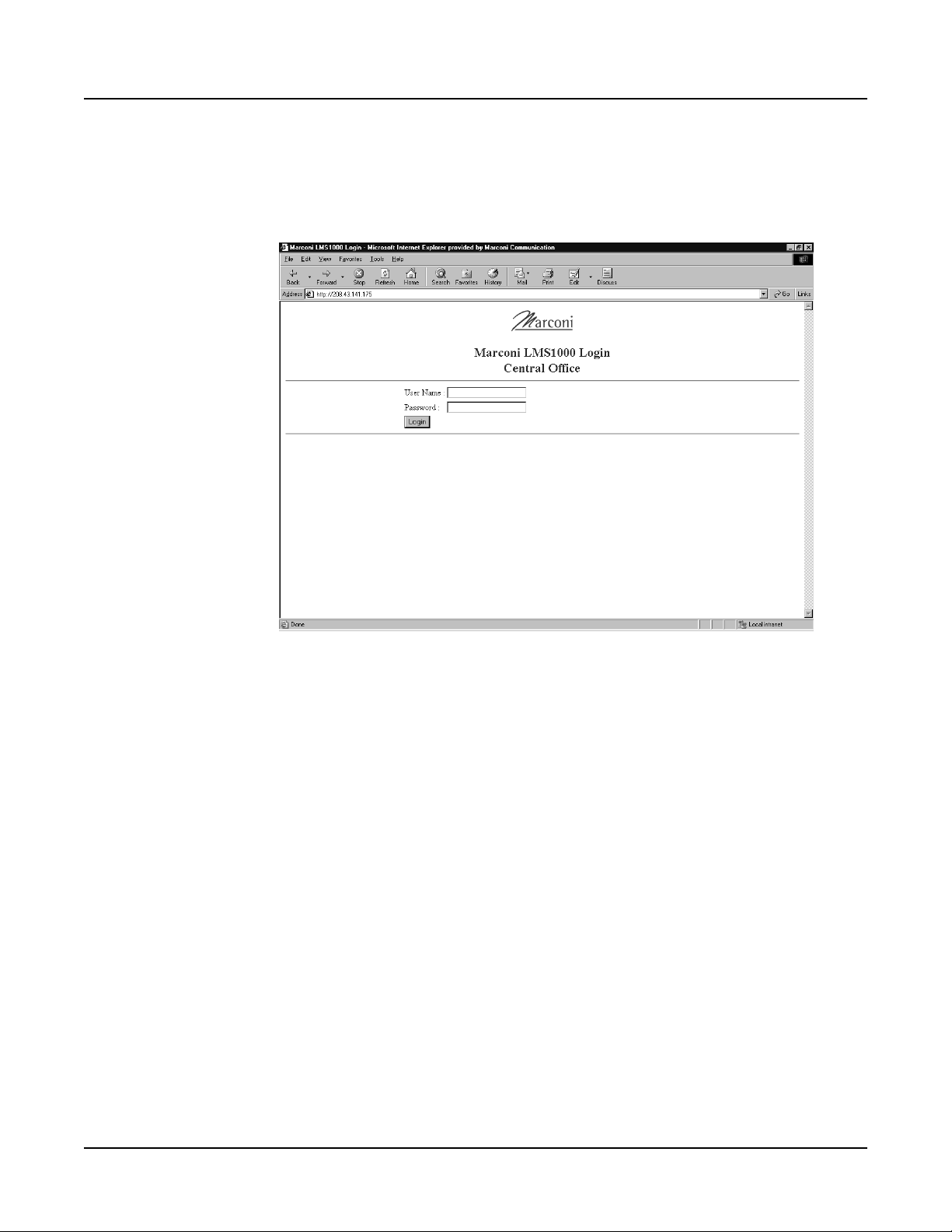
Section 5847 User Instructions
Issue AL, July 24, 2006 Spec. Nos. 586505000 and 5865055000 (Model LMS1000)
Using the LMS WEB Interface
1) Open your WEB Browser, and enter in the "Address Line" the IP Address assigned to
the LMS you want to connect to.
2) A Login page appears. Enter a valid LMS "User Name" and "User Password".
Login Screen
Warning: For security, only login with a User and Password which gives you
access to level 1 LMS commands (Level 1 User).
3) The three-pane WEB Interface window opens after a successful login.
Page 2-50 Chapter 2. Operating LMS1000
This document is property of Emerson Network Power, Energy Systems, North America, Inc. and contains confidential and proprietary information owned by Emerson Network Power, Energy
Systems, North America, Inc. Any copying, use, or disclosure of it without the written permission of Emerson Network Power, Energy Systems, North America, Inc. is strictly prohibited.
Page 71
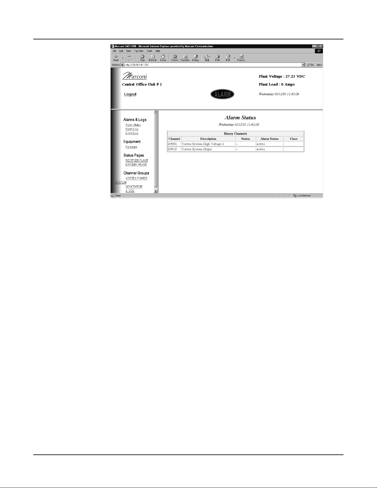
User Instructions Section 5847
Spec. Nos. 586505000 and 5865055000 (Model LMS1000) Issue AL, July 24, 2006
Three-Pane WEB Interface Window
4) The Top Pane displays the Unit Name and values of the Plant Voltage and Plant
Current LMS Channels. An ALARM message displays if there are active alarms in
the LMS.
5) Click on an item in the Left Pane to display its status in the Right Pane.
Note: Entries under Status Pages and Channel Groups only appear if properly
configured in the LMS, as previously explained under "Advance Setup"
What Do I Need, How Do I Order?
• Netscape Navigator, v4.0 or later
or
Microsoft Internet Explorer, v4.0 or later
• Order 586505000/586505500 List 81, and have an Emerson Network Power Service
Center load the new firmware into your LMS. Firmware can be upgraded via the
Ethernet, Modem, or Local Port.
Note: If you have an LMS1000 with firmware version earlier than 2.1.0.6, you must
replace the entire CPU circuit card. Earlier versions are not software
upgradeable.
Chapter 2. Operating LMS1000 Page 2-51
This document is property of Emerson Network Power, Energy Systems, North America, Inc. and contains confidential and proprietary information owned by Emerson Network Power, Energy
Systems, North America, Inc. Any copying, use, or disclosure of it without the written permission of Emerson Network Power, Energy Systems, North America, Inc. is strictly prohibited.
Page 72
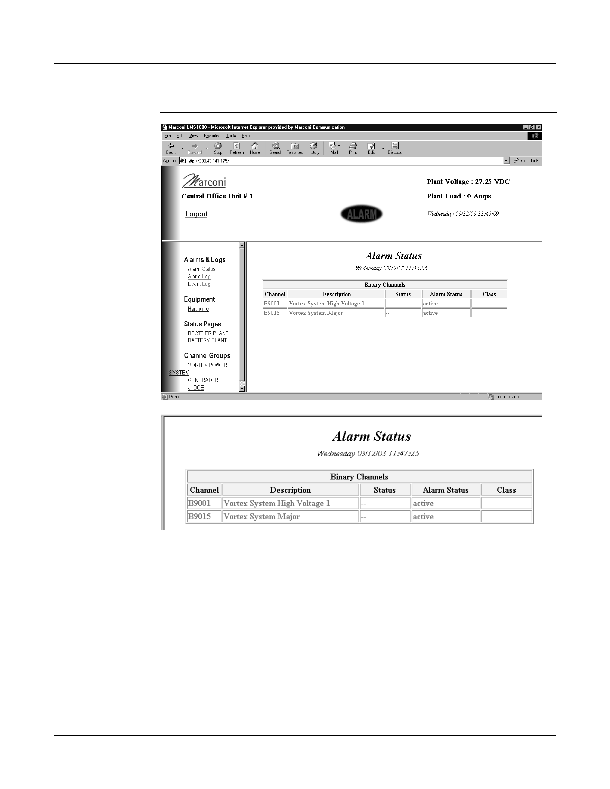
Section 5847 User Instructions
Issue AL, July 24, 2006 Spec. Nos. 586505000 and 5865055000 (Model LMS1000)
Sample Screen Shots
Alarm Status Page
Page 2-52 Chapter 2. Operating LMS1000
This document is property of Emerson Network Power, Energy Systems, North America, Inc. and contains confidential and proprietary information owned by Emerson Network Power, Energy
Systems, North America, Inc. Any copying, use, or disclosure of it without the written permission of Emerson Network Power, Energy Systems, North America, Inc. is strictly prohibited.
Page 73
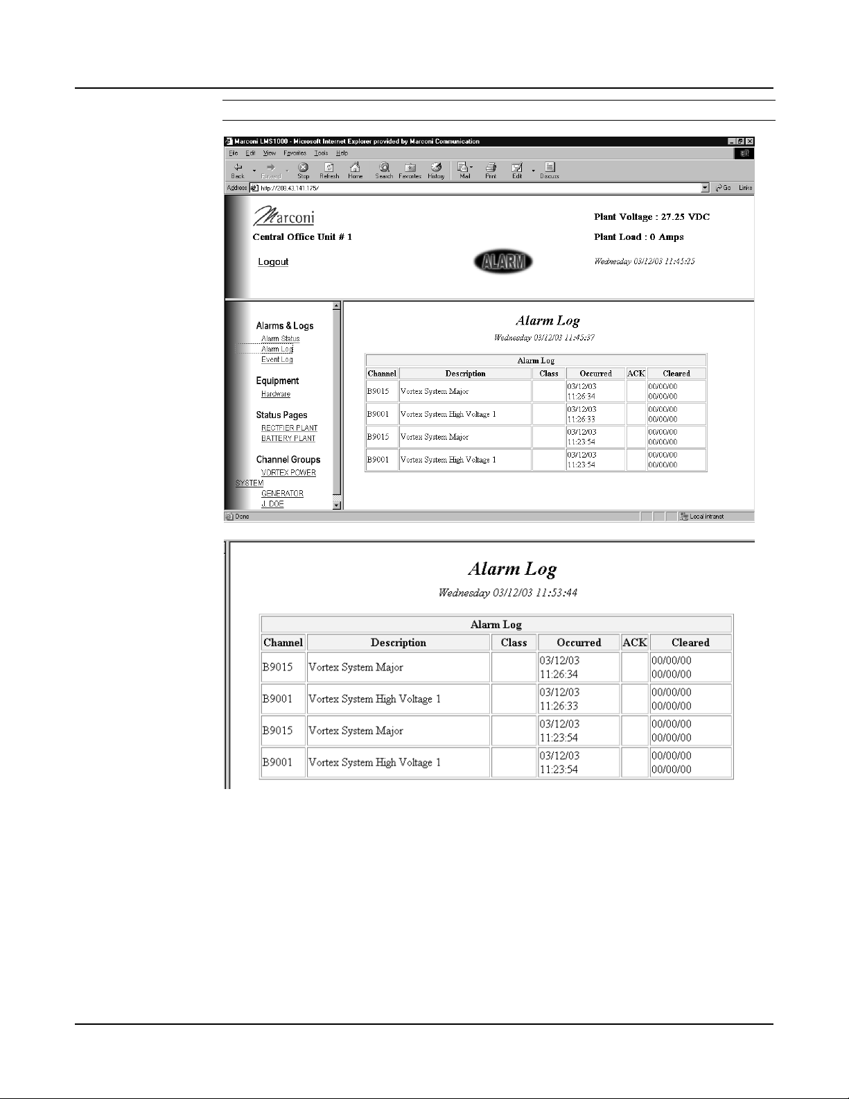
User Instructions Section 5847
Spec. Nos. 586505000 and 5865055000 (Model LMS1000) Issue AL, July 24, 2006
Alarm Log Page
Chapter 2. Operating LMS1000 Page 2-53
This document is property of Emerson Network Power, Energy Systems, North America, Inc. and contains confidential and proprietary information owned by Emerson Network Power, Energy
Systems, North America, Inc. Any copying, use, or disclosure of it without the written permission of Emerson Network Power, Energy Systems, North America, Inc. is strictly prohibited.
Page 74
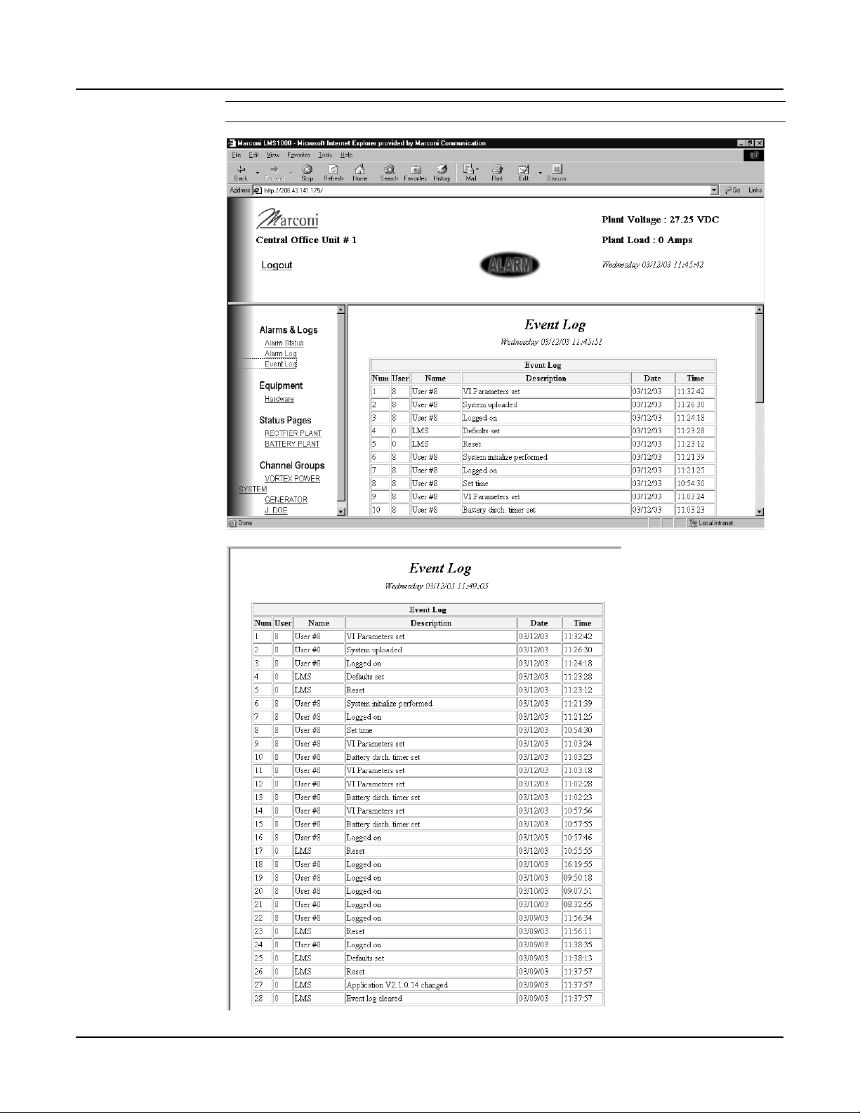
Section 5847 User Instructions
Issue AL, July 24, 2006 Spec. Nos. 586505000 and 5865055000 (Model LMS1000)
Event Log Page
Page 2-54 Chapter 2. Operating LMS1000
This document is property of Emerson Network Power, Energy Systems, North America, Inc. and contains confidential and proprietary information owned by Emerson Network Power, Energy
Systems, North America, Inc. Any copying, use, or disclosure of it without the written permission of Emerson Network Power, Energy Systems, North America, Inc. is strictly prohibited.
Page 75
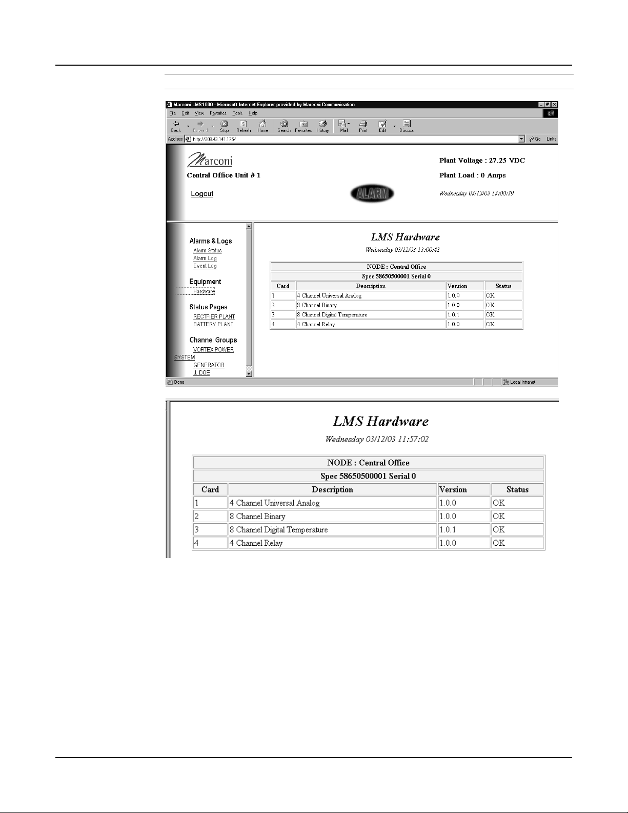
User Instructions Section 5847
Spec. Nos. 586505000 and 5865055000 (Model LMS1000) Issue AL, July 24, 2006
LMS Hardware Page
Chapter 2. Operating LMS1000 Page 2-55
This document is property of Emerson Network Power, Energy Systems, North America, Inc. and contains confidential and proprietary information owned by Emerson Network Power, Energy
Systems, North America, Inc. Any copying, use, or disclosure of it without the written permission of Emerson Network Power, Energy Systems, North America, Inc. is strictly prohibited.
Page 76
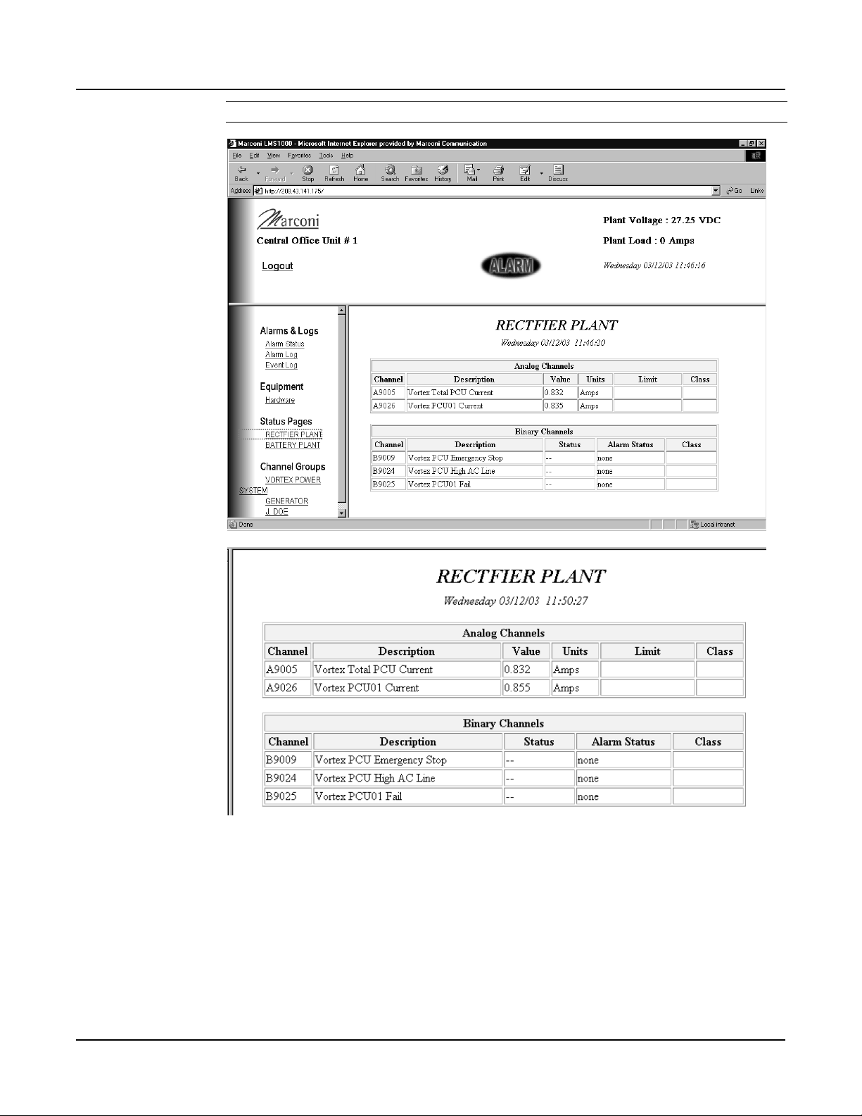
Section 5847 User Instructions
Issue AL, July 24, 2006 Spec. Nos. 586505000 and 5865055000 (Model LMS1000)
Sample Status Page
Page 2-56 Chapter 2. Operating LMS1000
This document is property of Emerson Network Power, Energy Systems, North America, Inc. and contains confidential and proprietary information owned by Emerson Network Power, Energy
Systems, North America, Inc. Any copying, use, or disclosure of it without the written permission of Emerson Network Power, Energy Systems, North America, Inc. is strictly prohibited.
Page 77
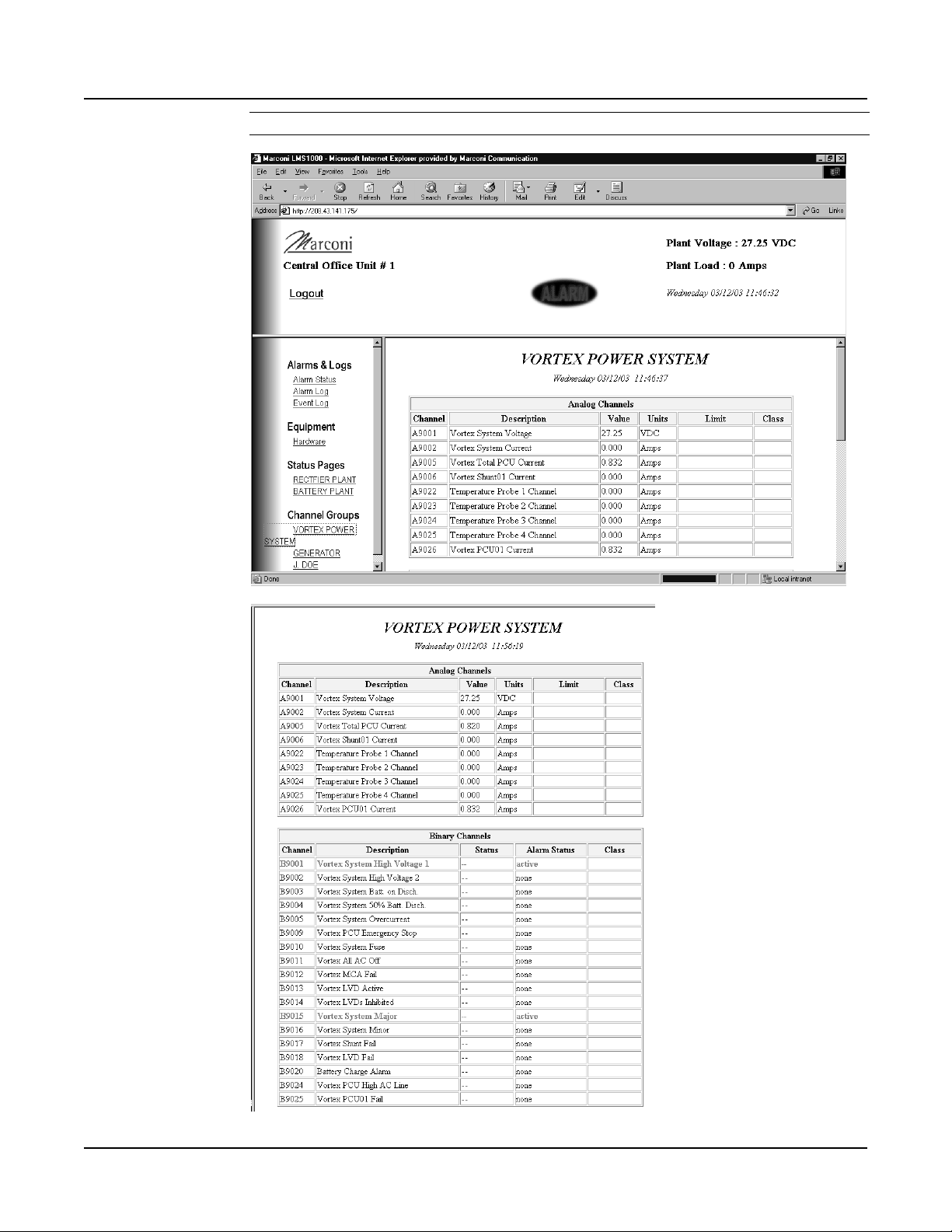
User Instructions Section 5847
Spec. Nos. 586505000 and 5865055000 (Model LMS1000) Issue AL, July 24, 2006
Sample Channel Group Page
Chapter 2. Operating LMS1000 Page 2-57
This document is property of Emerson Network Power, Energy Systems, North America, Inc. and contains confidential and proprietary information owned by Emerson Network Power, Energy
Systems, North America, Inc. Any copying, use, or disclosure of it without the written permission of Emerson Network Power, Energy Systems, North America, Inc. is strictly prohibited.
Page 78
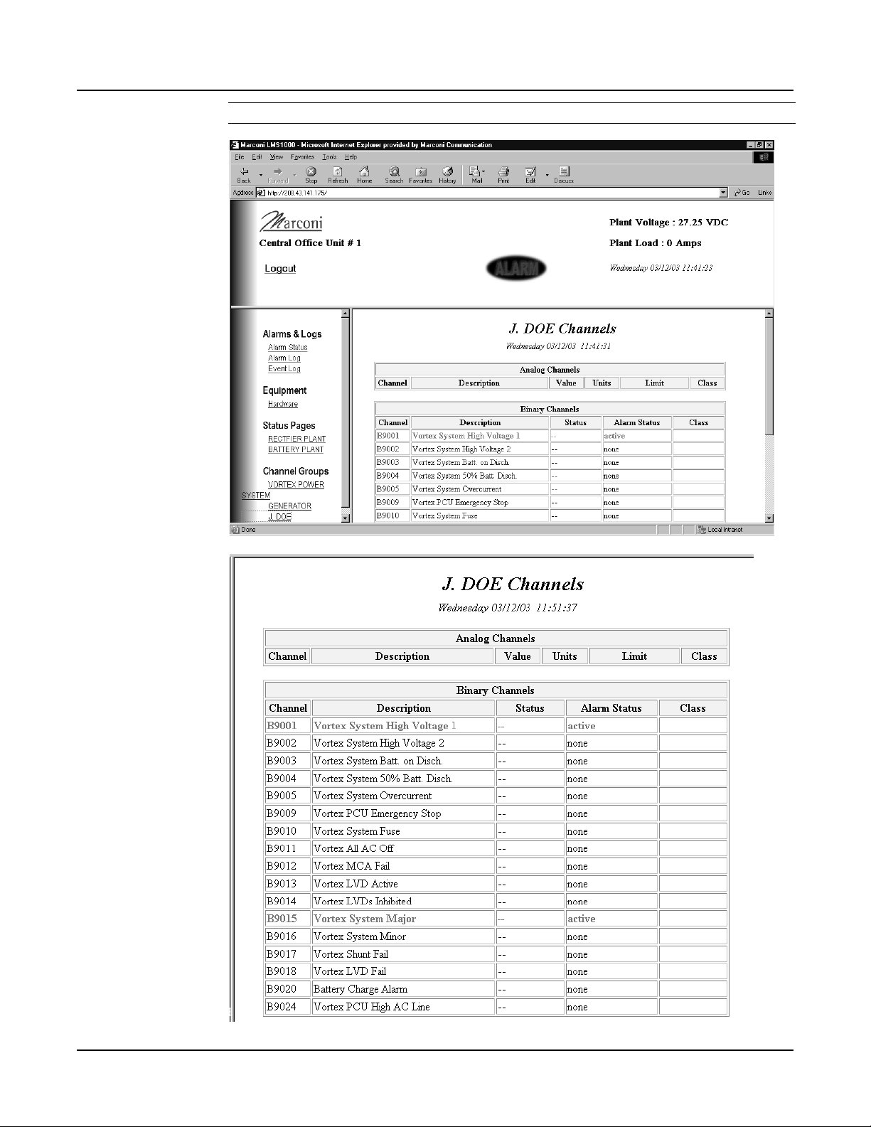
Section 5847 User Instructions
Issue AL, July 24, 2006 Spec. Nos. 586505000 and 5865055000 (Model LMS1000)
User Channel Page
Page 2-58 Chapter 2. Operating LMS1000
This document is property of Emerson Network Power, Energy Systems, North America, Inc. and contains confidential and proprietary information owned by Emerson Network Power, Energy
Systems, North America, Inc. Any copying, use, or disclosure of it without the written permission of Emerson Network Power, Energy Systems, North America, Inc. is strictly prohibited.
Page 79

User Instructions Section 5847
Spec. Nos. 586505000 and 5865055000 (Model LMS1000) Issue AL, July 24, 2006
USING THE BATTERY DISCHARGE TIMER FEATURE
Refer also to the Commands chapter for typical screen displays of the commands
described in this section.
What is the Battery Discharge Timer Feature?
The LMS can record Battery Discharge History. The Battery Discharge Timer feature
displays the last 50 recorded discharges in a tabular format. The information displayed
includes the duration of the battery discharge, the time and date at which the discharge
began, the lowest recorded plant voltage during the discharge, and the average plant
load.
Setting Up the Battery Discharge Timer Feature
A Binary, LED, or Relay channel must be identified to monitor the "On Battery" condition.
A Binary input may be used with external equipment that detects the system is "On
Battery". The program line of a Relay or LED channel can be used for more
sophisticated detection of the "On Battery" condition. Refer to the "Program Lines"
section of the "Configuration" chapter in the LMS Installation Instructions (Section 5879)
for further details on setting a Program Line. Analog or Function channels must be
identified to monitor the Plant Voltage and Plant Load.
Enter the command BATTERY TIMER SET. When prompted, enter the channels
monitoring the "On Battery Signal", "Plant Voltage", and "Plant Load".
Configure the "On Battery" channel as required for your installation site.
Using the Battery Discharge Timer Feature
Enter the command BATTERY TIMER STATUS to display the Battery Discharge History.
Use the command BATTERY TIMER CSV to display the data in a comma separated
format. To clear the Battery Discharge History, use the command BATTERY TIMER
CLR.
Chapter 2. Operating LMS1000 Page 2-59
This document is property of Emerson Network Power, Energy Systems, North America, Inc. and contains confidential and proprietary information owned by Emerson Network Power, Energy
Systems, North America, Inc. Any copying, use, or disclosure of it without the written permission of Emerson Network Power, Energy Systems, North America, Inc. is strictly prohibited.
Page 80

Section 5847 User Instructions
Issue AL, July 24, 2006 Spec. Nos. 586505000 and 5865055000 (Model LMS1000)
USING THE DOOR ACCESS CONTROLLER INTERFACE
(WHEN 586505000/586505500 LIST 80 INSTALLED)
Refer to the documentation furnished with the Door Access Controller.
Note that two events are added to the Event Log ('key code nn validated' and 'invalid key
code entered').
Note also that two Programmable Commands may have been configured to manually
lock and unlock the Access Door via LMS if the Door Access Controller should fail.
The following LMS binary channels are added.
Channel
Number
B7001 DAC Communications Failure
B7002 Strike Failed
B7003 Forced Entry
B7004 DAC PIN List Invalid
B7005 Door Open
Channel Name
USING THE EXTERNAL GPS MODEM INTERFACE
(WHEN 586505000/586505500 LIST 84 INSTALLED)
Refer to the documentation furnished with the GPS Modem.
The LMS operates at 19200, n, 8, 1.
Page 2-60 Chapter 2. Operating LMS1000
This document is property of Emerson Network Power, Energy Systems, North America, Inc. and contains confidential and proprietary information owned by Emerson Network Power, Energy
Systems, North America, Inc. Any copying, use, or disclosure of it without the written permission of Emerson Network Power, Energy Systems, North America, Inc. is strictly prohibited.
Page 81

User Instructions Section 5847
Spec. Nos. 586505000 and 5865055000 (Model LMS1000) Issue AL, July 24, 2006
USING THE AC ANALYZER INTERFACE
(WHEN 586505000/586505500 LIST 85 INSTALLED)
Refer to the documentation furnished with the AC Analyzer. LMS AC Analyzer Interface
is 9600, n, 8, 1. Set the AC Analyzer to 9600, n, 8, 1 as node #1.
The following LMS analog and binary channels are added.
Channel
Number
Channel Name
A7101 Phase 1 Voltage (VAC)
A7102 Phase 2 Voltage (VAC)
A7103 Phase 3 Voltage (VAC)
A7104 Phase 1-2 Voltage (VAC)
A7105 Phase 2-3 Voltage (VAC)
A7106 Phase 1-3 Voltage (VAC)
A7107 Phase 1 Current (AMPS)
A7108 Phase 2 Current (AMPS)
A7109 Phase 3 Current (AMPS)
A7110 Phase 1 Power Factor
A7111 Phase 2 Power Factor
A7112 Phase 3 Power Factor
A7113 Phase 1 Apparent Power (VA)
A7114 Phase 2 Apparent Power (VA)
A7115 Phase 3 Apparent Power (VA)
A7116 Phase 1 Real Power (W)
A7117 Phase 2 Real Power (W)
A7118 Phase 3 Real Power (W)
A7119 Phase 1 Reactive Power (VAR)
A7120 Phase 2 Reactive Power (VAR)
A7121 Phase 3 Reactive Power (VAR)
A7122 Average Voltage (VAC)
A7123 Average Current (AMPS)
A7124 Average Power Factor
A7125 Average Apparent Power (VA)
A7126 Average Real Power (W)
A7127 Average Reactive Power (VAR)
A7128 Frequency (HZ)
A7129 Real Energy (WH)
A7130 Reactive Energy (VARH)
A7131 Average Real Pwr., 15m (W)
A7132 Average Reactive Pwr., 15m (VAR)
B7101 AC Analyzer Com. Failure
Chapter 2. Operating LMS1000 Page 2-61
This document is property of Emerson Network Power, Energy Systems, North America, Inc. and contains confidential and proprietary information owned by Emerson Network Power, Energy
Systems, North America, Inc. Any copying, use, or disclosure of it without the written permission of Emerson Network Power, Energy Systems, North America, Inc. is strictly prohibited.
Page 82

Section 5847 User Instructions
N
g
Issue AL, July 24, 2006 Spec. Nos. 586505000 and 5865055000 (Model LMS1000)
LMS ALARM LIMIT OPTIONS
LMS v6.3 contains an enhanced version of alarm processing that allows for a more
intuitive use of alarm limits when used with plant voltage and battery shunts. The new
capability is made possible with an additional analog channel configuration item, alarm
polarity, which governs how high and low alarms operate. The default alarm processing
is the same as earlier LMS revisions – a high alarm occurs when the reading is greater
than the high limit, and a low alarm occurs when the reading is less than the low limit.
LMS v6.3 introduces two new modes of operation intended for analog inputs that have
bipolar or negative readings.
• In the polarized mode, a high or low alarm can
only occur if the polarity of the alarm matches
the polarity of the reading. This is useful for
detecting both high charge and discharge
currents on a battery shunt. For example,
assume a shunt is wired for a negative float
current reading, and it has a high alarm limit of
–6.0 amps to detect a high float current. It
can then also have a high limit of +100.0
amps to detect a high discharge current. So,
in this example there are two high alarms, with
opposite polarity. In previous versions of
LMS, this was not permitted. To select the
polarized mode, enter a “P” at the alarm
polarity prompt.
Amps
Limit 2 100.0 H
Limit 1 -6.0 H
0
Charge
egative alarm limits
are only used when the
reading is negative.
• In the negative mode, the alarm processing is
reversed from the default behavior. In other
words, a high alarm occurs when the reading
is less than the high limit, and a low alarm
occurs when the reading is the greater than
low limit. This is intended for inputs when the
reading is always negative, such as plant
voltage, making it possible to have
conventional alarm limits. Now, -56.0V can
be a high limit (given a float voltage of
-54.0V), when in previous LMS versions, it
must be a low limit. To select the negative
mode, enter a “–“ (minus sign) at the alarm
polarity prompt.
• In the default mode, the polarity of readings
and alarm limits are in fact used during alarm
processing, meaning evaluations are relative
(and not absolute). Furthermore, a reading is
compared to all alarm limits. So, in the
example at right and with a temperature of
-4.0 °C, two low alarms would turn in: one for
+5.0 limit and one for the -3.0 limit. The
default mode can be selected by entering a
“+“ (plus sign) at the alarm polarity prompt.
0
Limit 2 -48.0 L
Limit 1 -54.0 H
-Volts
Temp
Limit 3 30.0 H
Limit 2 5.0 L
Limit 1 -3.0 L
With v6.3, the –48.0
limit can now be a low
limit, while the –54.0
limit can be a hi
In the default mode, it is
possible to have low alarms
above and below zero
h.
0
Page 2-62 Chapter 2. Operating LMS1000
This document is property of Emerson Network Power, Energy Systems, North America, Inc. and contains confidential and proprietary information owned by Emerson Network Power, Energy
Systems, North America, Inc. Any copying, use, or disclosure of it without the written permission of Emerson Network Power, Energy Systems, North America, Inc. is strictly prohibited.
Page 83

User Instructions Section 5847
Spec. Nos. 586505000 and 5865055000 (Model LMS1000) Issue AL, July 24, 2006
CHAPTER 3
COMMANDS
TABLE OF CONTENTS
Overview of the Command Set........................................................................................ 3-8
LMS1000 Commands ............................................................................................... 3-8
Vortex® Power System (VPS) Interface Commands .............................................. 3-11
LPS Power System Interface Commands .............................................................. 3-13
IP Networking Commands ...................................................................................... 3-15
SNMP Commands .................................................................................................. 3-16
TL1 Commands Supported..................................................................................... 3-17
LMS1000 Commands, Vortex® Power System (VPS) Interface Commands, and
LPS Power System Interface Commands (in alphabetical order)................................. 3-20
Sample Command .................................................................................................. 3-21
Command Conventions and Options...................................................................... 3-22
ACK......................................................................................................................... 3-24
ACO ........................................................................................................................ 3-25
AID .......................................................................................................................... 3-26
ALARMS ................................................................................................................. 3-27
ALARMS VORTEX.................................................................................................. 3-29
ANSWER ................................................................................................................ 3-33
BATTERY................................................................................................................ 3-34
BATTERY THERMAL ............................................................................................. 3-35
BATTERY TIMER ................................................................................................... 3-36
BATTERY TIMER ? ................................................................................................ 3-37
BATTERY TIMER CLR ........................................................................................... 3-38
BATTERY TIMER CSV........................................................................................... 3-39
BATTERY TIMER SET ........................................................................................... 3-40
BATTERY TIMER STATUS .................................................................................... 3-41
BOARDS ................................................................................................................. 3-42
BYE ......................................................................................................................... 3-44
CHANNELS............................................................................................................. 3-45
CLASS .................................................................................................................... 3-46
CLR ......................................................................................................................... 3-47
CLR ACO ................................................................................................................ 3-48
CLR EVENTS.......................................................................................................... 3-49
CLR LED ................................................................................................................. 3-50
CLR LOG ................................................................................................................ 3-51
CLR MAIL................................................................................................................ 3-52
CLR POWER .......................................................................................................... 3-53
CLR PROGRAM ..................................................................................................... 3-54
CLR RLY ................................................................................................................. 3-55
CLR STATS ............................................................................................................ 3-56
Chapter 3. Commands Page 3-1
This document is property of Emerson Network Power, Energy Systems, North America, Inc. and contains confidential and proprietary information owned by Emerson Network Power, Energy
Systems, North America, Inc. Any copying, use, or disclosure of it without the written permission of Emerson Network Power, Energy Systems, North America, Inc. is strictly prohibited.
Page 84

Section 5847 User Instructions
Issue AL, July 24, 2006 Spec. Nos. 586505000 and 5865055000 (Model LMS1000)
CMD ........................................................................................................................ 3-57
COM........................................................................................................................ 3-58
CONFIG .................................................................................................................. 3-59
CONNECT .............................................................................................................. 3-68
DAC DEL................................................................................................................. 3-70
DAC LIST ................................................................................................................ 3-71
DAC SET................................................................................................................. 3-72
DAC SET LOCK OFF ............................................................................................. 3-73
DAC SET LOCK ON ............................................................................................... 3-74
DAC STATUS ......................................................................................................... 3-75
DATE....................................................................................................................... 3-76
DOWNLOAD........................................................................................................... 3-77
DOWNLOAD TFTP................................................................................................. 3-78
DOWNLOAD VORTEX ........................................................................................... 3-79
EFF ......................................................................................................................... 3-80
EVENTS.................................................................................................................. 3-81
HELP....................................................................................................................... 3-84
HELP VORTEX ....................................................................................................... 3-91
INFO........................................................................................................................ 3-93
LIMITS..................................................................................................................... 3-94
LOG......................................................................................................................... 3-96
MAIL........................................................................................................................ 3-98
MENU...................................................................................................................... 3-99
MODE ................................................................................................................... 3-101
NETWORK............................................................................................................ 3-102
NETWORK INITIALIZE......................................................................................... 3-103
NODE.................................................................................................................... 3-105
NODE ADD ........................................................................................................... 3-106
NODE CONFIG..................................................................................................... 3-108
NODE DELETE..................................................................................................... 3-110
NODE INITIO ........................................................................................................ 3-112
NODE LIST ........................................................................................................... 3-114
NODE REPLACE .................................................................................................. 3-116
OPTIONS .............................................................................................................. 3-118
PERIODS .............................................................................................................. 3-119
PHONE ................................................................................................................. 3-120
POWER................................................................................................................. 3-121
PRCONFIG ........................................................................................................... 3-123
PRCONFIG LPS ................................................................................................... 3-126
PRCONFIG VORTEX ........................................................................................... 3-139
PROGRAM............................................................................................................ 3-142
RATE..................................................................................................................... 3-143
REPORT ............................................................................................................... 3-144
SCAN .................................................................................................................... 3-145
Page 3-2 Chapter 3. Commands
This document is property of Emerson Network Power, Energy Systems, North America, Inc. and contains confidential and proprietary information owned by Emerson Network Power, Energy
Systems, North America, Inc. Any copying, use, or disclosure of it without the written permission of Emerson Network Power, Energy Systems, North America, Inc. is strictly prohibited.
Page 85

User Instructions Section 5847
Spec. Nos. 586505000 and 5865055000 (Model LMS1000) Issue AL, July 24, 2006
SCAN VORTEX .................................................................................................... 3-147
SEQUENCE .......................................................................................................... 3-151
SET ....................................................................................................................... 3-152
SET ACO .............................................................................................................. 3-153
SET AID ................................................................................................................ 3-154
SET ANSWER ...................................................................................................... 3-156
SET CHANNELS................................................................................................... 3-157
SET CLASS .......................................................................................................... 3-158
SET CMD .............................................................................................................. 3-159
SET COM.............................................................................................................. 3-161
SET DATE............................................................................................................. 3-162
SET DEFAULTS ................................................................................................... 3-163
SET EFF ............................................................................................................... 3-165
SET EMAIL ........................................................................................................... 3-166
SET GATEWAY .................................................................................................... 3-167
SET INFO.............................................................................................................. 3-168
SET LED ............................................................................................................... 3-169
SET LIMITS........................................................................................................... 3-170
SET LPS ............................................................................................................... 3-174
SET LPS CANIO ................................................................................................... 3-176
SET LPS MESSAGE CANIO_BD ......................................................................... 3-178
SET LPS MESSAGE DISTRIBUTION .................................................................. 3-179
SET LPS MESSAGE MCA ................................................................................... 3-180
SET LPS MESSAGE PCU.................................................................................... 3-181
SET LPS MESSAGE RELAY................................................................................ 3-182
SET LPS MESSAGE ROUTER ............................................................................ 3-183
SET LPS PASSWORD ......................................................................................... 3-184
SET LPS PCU....................................................................................................... 3-185
SET LPS SYSTEM BATONDISCH....................................................................... 3-186
SET LPS SYSTEM CURLIMIT ............................................................................. 3-187
SET LPS SYSTEM EQMULTIPLIER .................................................................... 3-188
SET LPS SYSTEM FLTVOLT............................................................................... 3-189
SET LPS SYSTEM HI1TEMPALM ....................................................................... 3-190
SET LPS SYSTEM HI2TEMPALM ....................................................................... 3-191
SET LPS SYSTEM HIVLTALM1........................................................................... 3-192
SET LPS SYSTEM HIVLTALM2........................................................................... 3-193
SET LPS SYSTEM HVS ....................................................................................... 3-194
SET LPS SYSTEM LOADACURRENT ................................................................ 3-195
SET LPS SYSTEM LOADBCURRENT ................................................................ 3-196
SET LPS SYSTEM LOADCURRENT ................................................................... 3-197
SET LPS SYSTEM LOW1TEMPALM................................................................... 3-198
SET LPS SYSTEM LOW2TEMPALM................................................................... 3-199
SET LPS SYSTEM NAGTIMER ........................................................................... 3-200
SET LPS SYSTEM RLYOFFTEST ....................................................................... 3-201
Chapter 3. Commands Page 3-3
This document is property of Emerson Network Power, Energy Systems, North America, Inc. and contains confidential and proprietary information owned by Emerson Network Power, Energy
Systems, North America, Inc. Any copying, use, or disclosure of it without the written permission of Emerson Network Power, Energy Systems, North America, Inc. is strictly prohibited.
Page 86

Section 5847 User Instructions
Issue AL, July 24, 2006 Spec. Nos. 586505000 and 5865055000 (Model LMS1000)
SET LPS SYSTEM RLYONTEST......................................................................... 3-202
SET LPS SYSTEM RLYTSTTIME ........................................................................ 3-203
SET LPS SYSTEM TEMPCOMPMAX.................................................................. 3-204
SET LPS SYSTEM TEMPCOMPMIN................................................................... 3-205
SET LPS SYSTEM TEMPSLOPE ........................................................................ 3-206
SET LPS SYSTEM TSTEQMODE........................................................................ 3-207
SET LPS SYSTEM TSTEQTIME.......................................................................... 3-208
SET LPS SYSTEM TSTEQVOLT ......................................................................... 3-209
SET LPS SYSTEM UPDATEINV.......................................................................... 3-210
SET LPS SYSTEM USECELSIUS........................................................................ 3-211
SET LPS SYSTEM USEFAHRENHEIT ................................................................ 3-212
SET LPS SYSTEM VERYLOWVOLT................................................................... 3-213
SET MAIL.............................................................................................................. 3-214
SET MODE ........................................................................................................... 3-215
SET PERIODS ...................................................................................................... 3-218
SET PHONE ......................................................................................................... 3-219
SET PROGRAM.................................................................................................... 3-221
SET REPORT ....................................................................................................... 3-222
SET RLY ............................................................................................................... 3-223
SET SEQUENCE .................................................................................................. 3-224
SET STATUS ........................................................................................................ 3-226
SET SYSTEM ....................................................................................................... 3-228
SET TIME.............................................................................................................. 3-233
SET TIMEOUT ...................................................................................................... 3-234
SET UNIT.............................................................................................................. 3-235
SET USERS.......................................................................................................... 3-236
SET VI................................................................................................................... 3-239
SET VORTEX ....................................................................................................... 3-240
SET VORTEX INTERFACE.................................................................................. 3-242
SET VORTEX LVD DISCONNECT ...................................................................... 3-243
SET VORTEX LVD RECONNECT ....................................................................... 3-244
SET VORTEX MESSAGE MCA ........................................................................... 3-245
SET VORTEX MESSAGE PCU............................................................................ 3-246
SET VORTEX PASSWORD ................................................................................. 3-247
SET VORTEX PCU............................................................................................... 3-248
SET VORTEX SUBSYSTEM CALVOLT .............................................................. 3-249
SET VORTEX SUBSYSTEM FACTORYCAL....................................................... 3-250
SET VORTEX SUBSYSTEM HIVALM ................................................................. 3-251
SET VORTEX SUBSYSTEM LVALM ................................................................... 3-252
SET VORTEX SUBSYSTEM OVRCURRENT ..................................................... 3-253
SET VORTEX SYSTEM 25APLACES.................................................................. 3-254
SET VORTEX SYSTEM 50APLACES.................................................................. 3-255
SET VORTEX SYSTEM 100APLACES................................................................ 3-256
SET VORTEX SYSTEM 200APLACES................................................................ 3-257
Page 3-4 Chapter 3. Commands
This document is property of Emerson Network Power, Energy Systems, North America, Inc. and contains confidential and proprietary information owned by Emerson Network Power, Energy
Systems, North America, Inc. Any copying, use, or disclosure of it without the written permission of Emerson Network Power, Energy Systems, North America, Inc. is strictly prohibited.
Page 87

User Instructions Section 5847
Spec. Nos. 586505000 and 5865055000 (Model LMS1000) Issue AL, July 24, 2006
SET VORTEX SYSTEM 50%BATONDISCH ....................................................... 3-258
SET VORTEX SYSTEM BATONDISCH............................................................... 3-259
SET VORTEX SYSTEM CALVOLT...................................................................... 3-260
SET VORTEX SYSTEM CURLIMIT ..................................................................... 3-261
SET VORTEX SYSTEM FACTORYCAL .............................................................. 3-262
SET VORTEX SYSTEM FLTVOLT....................................................................... 3-263
SET VORTEX SYSTEM HIVLTALM1................................................................... 3-264
SET VORTEX SYSTEM HIVLTALM2................................................................... 3-265
SET VORTEX SYSTEM HVS ............................................................................... 3-266
SET VORTEX SYSTEM INVENTORY ................................................................. 3-267
SET VORTEX SYSTEM MODE............................................................................ 3-268
SET VORTEX SYSTEM NAGTIMER ................................................................... 3-269
SET VORTEX SYSTEM OVRCURRENT ............................................................. 3-270
SET VORTEX SYSTEM TEMPCOMP ................................................................. 3-271
SET VORTEX SYSTEM TSTEQVOLT................................................................. 3-272
STATS................................................................................................................... 3-273
STATUS ................................................................................................................ 3-274
TIME...................................................................................................................... 3-275
TIMEOUT .............................................................................................................. 3-276
UNIT...................................................................................................................... 3-277
UPLOAD ............................................................................................................... 3-278
UPLOAD TFTP ..................................................................................................... 3-279
UPLOAD VORTEX................................................................................................ 3-280
USERS.................................................................................................................. 3-281
VI........................................................................................................................... 3-283
IP Networking Commands (in alphabetical order)....................................................... 3-285
Sample Command ................................................................................................ 3-286
Command Conventions and Options.................................................................... 3-287
IP........................................................................................................................... 3-288
IP ADD .................................................................................................................. 3-289
IP ADDRESS ........................................................................................................ 3-290
IP DELETE............................................................................................................ 3-291
IP GATEWAY........................................................................................................ 3-292
IP NETMASK ........................................................................................................ 3-293
SNMP Commands (in alphabetical order)................................................................... 3-295
Sample Command ................................................................................................ 3-296
Command Conventions and Options.................................................................... 3-297
SNMP.................................................................................................................... 3-298
SNMP GET ........................................................................................................... 3-299
SNMP OFF............................................................................................................ 3-300
SNMP ON ............................................................................................................. 3-301
SNMP SET............................................................................................................ 3-302
TRAPS .................................................................................................................. 3-303
TRAPS ADD.......................................................................................................... 3-304
Chapter 3. Commands Page 3-5
This document is property of Emerson Network Power, Energy Systems, North America, Inc. and contains confidential and proprietary information owned by Emerson Network Power, Energy
Systems, North America, Inc. Any copying, use, or disclosure of it without the written permission of Emerson Network Power, Energy Systems, North America, Inc. is strictly prohibited.
Page 88

Section 5847 User Instructions
Issue AL, July 24, 2006 Spec. Nos. 586505000 and 5865055000 (Model LMS1000)
TRAPS DELETE ................................................................................................... 3-305
TRAPS OCCURRED ............................................................................................ 3-306
TRAPS OFF .......................................................................................................... 3-307
TRAPS ON............................................................................................................ 3-308
TRAPS PERSISTENT .......................................................................................... 3-309
TRAPS RETIRED ................................................................................................. 3-310
TRAPS VERSION................................................................................................. 3-311
TL1 Commands, Autonomous Messages, and Error Codes....................................... 3-313
TL1 Commands Supported (in alphabetical order) ..................................................... 3-315
ACTIVATE-USER (ACT-USER) ........................................................................... 3-316
ALLOW-MESSAGE-ALL (ALW-MSG-ALL) .......................................................... 3-317
CANCEL-USER (CANC-USER) ........................................................................... 3-318
DELETE-USER-SECURITY (DLT-USER-SECU)................................................. 3-319
EDIT-DATE_AND_TIME (ED-DAT) ...................................................................... 3-320
EDIT-PID (ED-PID) ............................................................................................... 3-321
EDIT-USER-SECURITY (ED-USER-SECU) ........................................................ 3-322
ENTER-USER-SECURITY (ENT-USER-SECU) .................................................. 3-324
INHIBIT-MESSAGE-ALL (INH-MSG-ALL)............................................................ 3-326
INITIALIZE-LOG(INIT-LOG) ................................................................................. 3-327
INITIALIZE-REGISTER (INIT-REG-{EQPT|ALL}) ................................................ 3-328
INITIALIZE SYSTEM (INIT-SYS).......................................................................... 3-330
OPERATE-ALARM CUTOFF (OPR-ACO-{EQPT|ALL}) ...................................... 3-332
OPERATE-EXTERNAL-CONTROL (OPR-EXT-CONT)....................................... 3-333
RELEASE-EXTERNAL-CONTROL (RLS-EXT-CONT) ........................................ 3-335
RETRIEVE-ALARM (RTRV-ALM-{EQPT|ALL}).................................................... 3-337
RETRIEVE-ALARM-ENVIRONMENT (RTRV-ALM-ENV) .................................... 3-340
RETRIEVE-ATTRIBUTE (RTRV-ATTR-{EQPT|ALL}) .......................................... 3-342
RETRIEVE-ATTRIBUTE-ENVIRONMENT (RTRV-ATTR-ENV) .......................... 3-344
RETRIEVE-CONDITION (RTRV-COND-{EQPT|ALL})......................................... 3-346
RETRIEVE-EXTERNAL-CONTROL (RTRV-EXT-CONT) .................................... 3-349
RETRIEVE-HEADER (RTRV-HDR)...................................................................... 3-351
RETRIEVE-LOG (RTRV-LOG) ............................................................................. 3-352
RETRIEVE-PERFORMANCE MONITORING (RTRV-PM-{EQPT|ALL}) ............. 3-353
RETRIEVE-THRESHOLD (RTRV-TH-{EQPT|ALL}) ............................................ 3-356
RETRIEVE-USER-SECURITY (RTRV-USER-SECU).......................................... 3-358
SET-ATTRIBUTE (SET-ATTR-{EQPT}) ............................................................... 3-359
SET-ATTRIBUTE-ENVIRONMENT (SET-ATTR-ENV) ........................................ 3-361
SET-SYSTEM_IDENTIFICATION (SET-SID)....................................................... 3-363
SET-THRESHOLD (SET-TH-{EQPT}).................................................................. 3-364
TL1 Autonomous Messages Supported (in alphabetical order).................................. 3-367
CANCEL SESSION (TIMEOUT)........................................................................... 3-368
REPORT ALARM (REPT ALM {EQPT/COM}) ..................................................... 3-369
REPORT ALARM ENVIRONMENT (REPT ALM ENV) ........................................ 3-372
REPORT CONDITION (REPT COND {EQPT/COM}) .......................................... 3-374
Page 3-6 Chapter 3. Commands
This document is property of Emerson Network Power, Energy Systems, North America, Inc. and contains confidential and proprietary information owned by Emerson Network Power, Energy
Systems, North America, Inc. Any copying, use, or disclosure of it without the written permission of Emerson Network Power, Energy Systems, North America, Inc. is strictly prohibited.
Page 89

User Instructions Section 5847
Spec. Nos. 586505000 and 5865055000 (Model LMS1000) Issue AL, July 24, 2006
REPORT EVENT (REPT EVT {EQPT/COM}) ...................................................... 3-376
List of Error Codes for TL1 Commands Supported (in alphabetical order)................. 3-379
Chapter 3. Commands Page 3-7
This document is property of Emerson Network Power, Energy Systems, North America, Inc. and contains confidential and proprietary information owned by Emerson Network Power, Energy
Systems, North America, Inc. Any copying, use, or disclosure of it without the written permission of Emerson Network Power, Energy Systems, North America, Inc. is strictly prohibited.
Page 90

Section 5847 User Instructions
Issue AL, July 24, 2006 Spec. Nos. 586505000 and 5865055000 (Model LMS1000)
OVERVIEW OF THE COMMAND SET
LMS1000 Commands
This section provides an alphabetical list of all LMS1000 commands, with a short
description of each command.
LMS1000 Commands Description
ACK
ACO
AID <n>
ALARMS
ANSWER
BATTERY
BATTERY THERMAL
BATTERY TIMER
BATTERY TIMER ?
BATTERY TIMER CLR
BATTERY TIMER CSV
BATTERY TIMER SET
BATTERY TIMER STATUS
BOARDS
BYE
CHANNELS
CLASS
CLR
CLR ACO
CLR EVENTS
CLR LED <n>
CLR LOG
CLR MAIL
CLR POWER <n>
CLR PROGRAM <tn>
CLR RLY <n>
CLR STATS <tn>
CMD
COM
CONFIG <tn>
CONNECT
DAC DEL
DAC LIST
acknowledge report type alarms
list alarms that have been cutoff
display configured access identifiers
list active alarms
show number of rings before the system answers
list BATTERY type commands
sets the Battery Thermal Alarm Channel and Battery Thermal Runaway
Voltage
list BATTERY TIMER type commands
display Help for BATTERY type commands
clear Battery Discharge History
display Battery Discharge History in comma separated value format
set Battery Discharge Timer feature
display Battery Discharge History in tabular format
list boards installed in the LMS1000 System Network
logoff and hang-up
list user defined channels
list programmable alarm classifications
list CLR type commands
disable alarm cutoff
clear event log
turn LED off
clear alarm log
clear your mail from memory
clear power consumption data (if Power Metering software option installed)
clear control programs
de-energize relay
clear channel statistics
list programmable commands
list local comm port settings
configure specified channel
initiate a communications session with device connected to GATEWAY port
Deletes a User from the Door Access Controller (DAC).
Displays a list of Users and their Access Codes stored in the Door Access
Controller (DAC).
Page 3-8 Chapter 3. Commands
This document is property of Emerson Network Power, Energy Systems, North America, Inc. and contains confidential and proprietary information owned by Emerson Network Power, Energy
Systems, North America, Inc. Any copying, use, or disclosure of it without the written permission of Emerson Network Power, Energy Systems, North America, Inc. is strictly prohibited.
Page 91

User Instructions Section 5847
Spec. Nos. 586505000 and 5865055000 (Model LMS1000) Issue AL, July 24, 2006
LMS1000 Commands Description
DAC SET
DAC SET LOCK OFF
DAC SET LOCK ON
DAC STATUS
DATE
DOWNLOAD
DOWNLOAD TFTP
EFF
EVENTS <n>
HELP
INFO <n>
LIMITS
LOG
MAIL
MENU
MODE
NETWORK
NETWORK INITIALIZE
NODE
NODE ADD
NODE CONFIG <n>
NODE DELETE <n>
NODE INITIO <n>
NODE LIST <n>
NODE REPLACE <n>
OPTIONS
PERIODS
PHONE
POWER <t<n>>
PRCONFIG
PROGRAM
RATE
REPORT
SCAN
SEQUENCE
SET
SET ACO
SET AID <n>
SET ANSWER <n>
SET CHANNELS
SET CLASS <n>
Adds / changes a User and/or Access Code stored in the Door Access
Controller (DAC).
Unlocks the access with any DAC User Code.
Locks the access with any DAC User Code.
Displays the actual state of the Access Door.
show date and time
dump system configuration using XMODEM protocol
performs a DUMP operation using TFTP
show Energy Management status
list event log entries for specified user
list of commands with a description of each
show information pages
list channel alarm limits
list alarm log entries
show any mail
list of commands
displays configuration of TL1 port settings
list NETWORK type commands
clear all known nodes and search for new nodes
list NODE type commands
search for and configure new nodes
configure user information for a node
remove a node
reinitialize a node's I/O hardware configuration
view user and hardware configuration for nodes
replace a node
list options installed
list time periods
show user phone numbers
list power consumption data (if Power Metering software option installed)
list channel configuration
list control programs
list size or capacity percentages
show system alarm reporting parameters
list active channel status
show AC & standby sequencer status
list SET type commands
cutoff present alarms from affecting relays
configures access identifiers
set number of rings before the system answers
set user defined channels
set programmable alarm classifications
Chapter 3. Commands Page 3-9
This document is property of Emerson Network Power, Energy Systems, North America, Inc. and contains confidential and proprietary information owned by Emerson Network Power, Energy
Systems, North America, Inc. Any copying, use, or disclosure of it without the written permission of Emerson Network Power, Energy Systems, North America, Inc. is strictly prohibited.
Page 92

Section 5847 User Instructions
Issue AL, July 24, 2006 Spec. Nos. 586505000 and 5865055000 (Model LMS1000)
LMS1000 Commands Description
SET CMD <n>
SET COM
SET DATE <mm/dd/yy>
SET DEFAULTS
SET EFF
SET EMAIL
SET GATEWAY
SET INFO <n>
SET LED <n>
SET LIMITS <tn>
SET MAIL
SET MODE
SET PERIODS <tn>
SET PHONE
SET PROGRAM <tn>
SET REPORT
SET RLY <n>
SET SEQUENCE
SET STATUS <n>
SET SYSTEM
SET TIME <hh:mm:ss>
SET TIMEOUT <n>
SET UNIT
SET USERS <n>
SET VI
STATS
STATUS <n>
TIME
TIMEOUT
UNIT
UPLOAD
set programmable commands
set local comm port configuration
set date where mm = month, dd = date, yy = year
set system default parameters
set Energy Management parameters
set Email Alarm Notification Parameters
set GATEWAY port communications data rate
configure information pages
turn LED on
set channel alarm limits
send mail to users
modify configuration of TL1 port settings
set time periods
set user phone numbers
configure control programs
set system alarm reporting parameters
energize relay
set AC & Standby sequencer parameters
configure status page
configure all settings
set time where hh = hours, mm = minutes, ss = seconds
set user timeout
set unit name and number
configure a user
sets the channels that display system voltage and system current
list channel statistics
show status page
show date and time
show user timeout
show unit name and number
configure the system by uploading file using XMODEM protocol
allows transfer of configuration information to the system from any networked
UPLOAD TFTP
personal computer capable of uploading and downloading a file to a disk using
the TFTP Protocol
USERS <n>
VI
list user configuration
show Plant Voltage and Load
where: < > anything enclosed in brackets is optional.
n is a valid number.
t is a type A, B, E, F, G, L, R; for Analog, Binary, Energy Management, Function, Group, LED, or
Relay.
Page 3-10 Chapter 3. Commands
This document is property of Emerson Network Power, Energy Systems, North America, Inc. and contains confidential and proprietary information owned by Emerson Network Power, Energy
Systems, North America, Inc. Any copying, use, or disclosure of it without the written permission of Emerson Network Power, Energy Systems, North America, Inc. is strictly prohibited.
Page 93

User Instructions Section 5847
Spec. Nos. 586505000 and 5865055000 (Model LMS1000) Issue AL, July 24, 2006
Vortex® Power System (VPS) Interface Commands
This section provides an alphabetical list of all Vortex Power System (VPS) Interface
commands, with a short description of each command.
Vortex
®
Power System (VPS)
Interface Commands
ALARMS VORTEX
ALARMS VORTEX LVD
ALARMS VORTEX MCA
ALARMS VORTEX PCU<n>
ALARMS VORTEX SHUNT
ALARMS VORTEX SUBSYSTEM
ALARMS VORTEX SYSTEM
DOWNLOAD VORTEX
HELP VORTEX
PRCONFIG VORTEX
PRCONFIG VORTEX
INVENTORY
PRCONFIG VORTEX
SETTINGS
SCAN VORTEX
SCAN VORTEX LVD
SCAN VORTEX MCA
SCAN VORTEX PCU<n>
SCAN VORTEX SUBSYSTEM
SCAN VORTEX SYSTEM
SET VORTEX
SET VORTEX INTERFACE
SET VORTEX LVD<n<t>>
DISCONNECT
SET VORTEX LVD
RECONNECT
SET VORTEX MESSAGE MCA
SET VORTEX MESSAGE
PCU<n>
SET VORTEX PASSWORD
SET VORTEX PCU<n>
SET VORTEX SUBSYSTEM
CALVOLT
SET VORTEX SUBSYSTEM
FACTORYCAL
SET VORTEX SUBSYSTEM
HIVALM
SET VORTEX SUBSYSTEM
LVALM
Description
list active Power System alarms
list active LVD alarms
list active MCA alarms
list active PCU alarms
list active SHUNT alarms
list active subsystem type alarms
list active system type alarms
dump Vortex Power System configuration using XMODEM protocol
list of Vortex Interface commands with a description of each
list settings and equipment inventory
list equipment inventory
list settings
list present status of Vortex Power System
list present status of LVD circuits
list present status of MCA
list present status of specified PCU
list present status of subsystem data
list present status of system data
configure Vortex Power System settings
Enable/Disable Vortex interface
set specified LVD disconnect voltage settings
set LVD reconnect voltage setting
set MCA custom message
set specified PCU custom message
set MCA logon password
turn specified PCU On or Off
set subsystem calibration voltage
set subsystem cal. voltage to factory default
set subsystem High Voltage alarm
set subsystem Low Voltage alarm
Chapter 3. Commands Page 3-11
This document is property of Emerson Network Power, Energy Systems, North America, Inc. and contains confidential and proprietary information owned by Emerson Network Power, Energy
Systems, North America, Inc. Any copying, use, or disclosure of it without the written permission of Emerson Network Power, Energy Systems, North America, Inc. is strictly prohibited.
Page 94

Section 5847 User Instructions
Issue AL, July 24, 2006 Spec. Nos. 586505000 and 5865055000 (Model LMS1000)
Vortex® Power System (VPS)
Interface Commands
SET VORTEX SUBSYSTEM
OVRCURRENT
SET VORTEX SYSTEM
25APLACES
SET VORTEX SYSTEM
50APLACES
SET VORTEX SYSTEM
100APLACES
SET VORTEX SYSTEM
200APLACES
SET VORTEX SYSTEM
50%BATONDISCH
SET VORTEX SYSTEM
BATONDISCH
SET VORTEX SYSTEM
CALVOLT
SET VORTEX SYSTEM
CURLIMIT
SET VORTEX SYSTEM
FACTORYCAL
SET VORTEX SYSTEM
FLTVOLT
SET VORTEX SYSTEM
HIVLTALM1
SET VORTEX SYSTEM
HIVLTALM2
SET VORTEX SYSTEM HVS
SET VORTEX SYSTEM
INVENTORY
SET VORTEX SYSTEM MODE
SET VORTEX SYSTEM
NAGTIMER
SET VORTEX SYSTEM
OVRCURRENT
SET VORTEX SYSTEM
TEMPCOMP
SET VORTEX SYSTEM
TSTEQVOLT
UPLOAD VORTEX
set subsystem Overcurrent alarm
set system number of 25A Places
set system number of 50A Places
set system number of 100A Places
set system number of 200A Places
set system 50% Battery On Discharge alarm
set system Battery On Discharge alarm
set system calibration voltage
set system current limit
set system cal. voltage to factory default
set system float voltage
set system High Voltage 1 Alarm
set system High Voltage 2 Alarm
set system High Voltage Shutdown
reset the system equipment inventory
set Vortex Power System mode
set system ACO timer
set system Overcurrent alarm
set system Temperature compensation voltage
set system test/equalize voltage
configure Vortex Power System by uploading file using XMODEM protocol
Description
where: < > anything enclosed in brackets is optional
n is a valid number
t is A or B for Vortex LVD settings
Page 3-12 Chapter 3. Commands
This document is property of Emerson Network Power, Energy Systems, North America, Inc. and contains confidential and proprietary information owned by Emerson Network Power, Energy
Systems, North America, Inc. Any copying, use, or disclosure of it without the written permission of Emerson Network Power, Energy Systems, North America, Inc. is strictly prohibited.
Page 95

User Instructions Section 5847
Spec. Nos. 586505000 and 5865055000 (Model LMS1000) Issue AL, July 24, 2006
LPS Power System Interface Commands
This section provides an alphabetical list of all LPS Power System Interface commands,
with a short description of each command.
LPS Power System
Interface Commands
PRCONFIG LPS
PRCONFIG LPS
DISTRIBUTION
PRCONFIG LPS INVENTORY
PRCONFIG LPS N<#>-<#>
PRCONFIG LPS PCU
PRCONFIG LPS SETTINGS
SET LPS
SET LPS CANIO
SET LPS MESSAGE
CANIO_BD
SET LPS MESSAGE
DISTRIBUTION
SET LPS MESSAGE MCA
SET LPS MESSAGE PCU<n>
SET LPS MESSAGE RELAY
SET LPS MESSAGE ROUTER
SET LPS PASSWORD
SET LPS PCU<n>
SET LPS SYSTEM
BATONDISCH
SET LPS SYSTEM CURLIMIT
SET LPS SYSTEM
EQMULTIPLIER
SET LPS SYSTEM FLTVOLT
SET LPS SYSTEM
HI1TEMPALM
SET LPS SYSTEM
HI2TEMPALM
SET LPS SYSTEM
HIVLTALM1
SET LPS SYSTEM
HIVLTALM2
Description
list settings and equipment inventory
list equipment inventory of Distribution Elements
list equipment inventory of all Elements
list equipment inventory of Bay/MCA Elements
list equipment inventory of PCU Elements
list settings
configure LPS Power System settings
set LPS MCA CAN I/O circuit card parameters
prompted to select which LPS MCA CAN I/O circuit card, then which
parameter to set
(configurable parameters are…
designate the alarm state for MCA CAN I/O circuit card binary inputs,
designate MCA CAN I/O circuit card analog input as "auxiliary" or
"distribution", set the scale factor for MCA CAN I/O circuit card analog input
and output)
set MCA CAN I/O circuit card custom messages
set Distribution Elements custom message
set MCA custom message
set specified PCU custom message
set Relay Elements custom message
set Router Elements custom message
set MCA logon password
turn specified PCU On or Off
set system Battery On Discharge alarm
set system current limit
set system "Auto-Equalize Time Multiplier"
set system float voltage
set system High Temperature 1 alarm
set system High Temperature 2 alarm
set system High Voltage 1 alarm
set system High Voltage 2 alarm
Chapter 3. Commands Page 3-13
This document is property of Emerson Network Power, Energy Systems, North America, Inc. and contains confidential and proprietary information owned by Emerson Network Power, Energy
Systems, North America, Inc. Any copying, use, or disclosure of it without the written permission of Emerson Network Power, Energy Systems, North America, Inc. is strictly prohibited.
Page 96

Section 5847 User Instructions
Issue AL, July 24, 2006 Spec. Nos. 586505000 and 5865055000 (Model LMS1000)
LPS Power System
Interface Commands
SET LPS SYSTEM HVS
SET LPS SYSTEM
LOADACURRENT
SET LPS SYSTEM
LOADBCURRENT
SET LPS SYSTEM
LOADCURRENT
SET LPS SYSTEM
LOW1TEMPALM
SET LPS SYSTEM
LOW2TEMPALM
SET LPS SYSTEM NAGTIMER
SET LPS SYSTEM
RLYOFFTEST
SET LPS SYSTEM
RLYONTEST
SET LPS SYSTEM
RLYTSTTIME
SET LPS SYSTEM
TEMPCOMPMAX
SET LPS SYSTEM
TEMPCOMPMIN
SET LPS SYSTEM
TEMPSLOPE
SET LPS SYSTEM TSTEMODE
SET LPS SYSTEM
TSTEQTIME
SET LPS SYSTEM
TSTEQVOLT
SET LPS SYSTEM
UPDATEINV
SET LPS SYSTEM
USECELSIUS
SET LPS SYSTEM
USEFAHRENHEIT
SET LPS SYSTEM
VERYLOWVOLT
set system High Voltage Shutdown
set system Load Group A Current alarm
set system Load Group B Current alarm
set system Total Load Current alarm
set system Low Temperature 1 alarm
set system Low Temperature 2 alarm
set system ACO timer
set system "alarm relay test feature" off
set system "alarm relay test feature" on
set system "alarm relay test feature time period"
set system "battery charge temperature compensation feature's maximum
voltage"
set system "battery charge temperature compensation feature's minimum
voltage"
set system "battery charge temperature compensation feature's compensation
slope"
set system to float or test/equalize mode
set system "timed equalize feature's equalize time period"
set system test/equalize voltage
reset the system equipment inventory
set system temperature readings to Celsius
set system temperature readings to Fahrenheit
set system Very Low Voltage alarm
Description
where: < > anything enclosed in brackets is optional
# is a valid number
N is a valid number
Page 3-14 Chapter 3. Commands
This document is property of Emerson Network Power, Energy Systems, North America, Inc. and contains confidential and proprietary information owned by Emerson Network Power, Energy
Systems, North America, Inc. Any copying, use, or disclosure of it without the written permission of Emerson Network Power, Energy Systems, North America, Inc. is strictly prohibited.
Page 97

User Instructions Section 5847
Spec. Nos. 586505000 and 5865055000 (Model LMS1000) Issue AL, July 24, 2006
IP Networking Commands
This section provides an alphabetical list of all IP Networking commands available when
the SNMP software option is installed, with a short description of each command.
IP Networking Commands Description
IP
IP ADD <address>
IP ADDRESS <address>
IP DELETE <address>
IP GATEWAY <address>
IP NETMASK <address>
display the IP Network variables
add a new host to the list of authorized hosts
set the units IP address
remove a host from the list of authorized hosts
set the units gateway address
set the units network netmask
Chapter 3. Commands Page 3-15
This document is property of Emerson Network Power, Energy Systems, North America, Inc. and contains confidential and proprietary information owned by Emerson Network Power, Energy
Systems, North America, Inc. Any copying, use, or disclosure of it without the written permission of Emerson Network Power, Energy Systems, North America, Inc. is strictly prohibited.
Page 98

Section 5847 User Instructions
Issue AL, July 24, 2006 Spec. Nos. 586505000 and 5865055000 (Model LMS1000)
SNMP Commands
This section provides an alphabetical list of all SNMP commands available when the
SNMP software option is installed, with a short description of each command.
SNMP Commands Description
SNMP
SNMP GET <comm name>
SNMP OFF
SNMP ON
SNMP SET <comm name>
TRAPS
TRAPS ADD <n>
TRAPS DELETE <n>
TRAPS OCCURRED
TRAPS OFF
TRAPS ON
TRAPS PERSISTENT
TRAPS RETIRED
TRAPS VERSION
display the current value of the SNMP options
set the SNMP GET community name
disable SNMP access
enable SNMP access
set the SNMP SET community name
display the SNMP TRAP information
add a new SNMP Trap recipient to the list of TRAP hosts
remove a host address from the list of TRAP hosts
disable/enable the systems ability to send SNMP Occurred Alarm TRAPS
disable the systems ability to send SNMP TRAPs
enable the system to send SNMP TRAPs
Disable/Enable the systems ability to send SNMP Persistent Alarm TRAPS or
set the Persistent Alarms reporting interval
Disable/Enable the systems ability to send SNMP Retired Alarm TRAPS
change the version of SNMP TRAPs sent by the system
Page 3-16 Chapter 3. Commands
This document is property of Emerson Network Power, Energy Systems, North America, Inc. and contains confidential and proprietary information owned by Emerson Network Power, Energy
Systems, North America, Inc. Any copying, use, or disclosure of it without the written permission of Emerson Network Power, Energy Systems, North America, Inc. is strictly prohibited.
Page 99

User Instructions Section 5847
Spec. Nos. 586505000 and 5865055000 (Model LMS1000) Issue AL, July 24, 2006
TL1 Commands Supported
This section provides an alphabetical list of all TL1 commands supported when the TL1
software option is installed, with a short description of each command.
Refer to the current issue of the following Bellcore publications for further TL1 command
language information.
TR-NWT-000199 TR-NWT-000835 TA-NWT-001360
TR-NWT-000831 TA-NWT-000199
TR-NWT-000833 TA-NWT-000200
TL1 Commands Supported Description
ACTIVATE-USER
ACT-USER
ALLOW-MESSAGE-ALL
ALW-MSG-ALL
CANCEL-USER
CANC-USER
DELETE-USER-SECURITY
DLT-USER-SECU
EDIT-DATE_AND_TIME
ED-DAT
EDIT-PID
ED-PID
EDIT-USER-SECURITY
ED-USER-SECU
ENTER-USER-SECURITY
ENT-USER-SECU
INHIBIT-MESSAGE-ALL
INH-MSG-ALL
INITIALIZE-LOG
INIT-LOG
INITIALIZE-REGISTER
INIT-REG-{EQPT|ALL}
INITIALIZE SYSTEM
INIT-SYS
OPERATE-ALARM CUTOFF
OPR-ACO-{EQPT|ALL}
OPERATE-EXTERNAL-CONTROL
OPR-EXT-CONT
Sets up a session with the system (i.e., logging into the
system.
Enables the system to resume transmission of automatic
messages after being placed in the inhibit message mode.
Terminates a session with the system (i.e., logging off of the
system).
Deactivates a user.
Changes the system’s date and/or time.
Edits the current user’s privilege identifier (<pid>) parameter
(i.e., the system's user password).
Edits the user identifier (<uid>) parameter (i.e., user name),
privilege identifier (<pid>) parameter (i.e., the password),
calling identifier (<cid>) parameter (i.e., user primary phone
number), and user access privilege (<uap>) parameter (i.e.,
user access level) of the specified user.
Activates a user and enters the specified security parameters
for this user. These security parameters consist of the user
identifier (<uid>) parameter (i.e., user name), privilege
identifier (<pid>) parameter (i.e., user password), calling
identifier (<cid>) parameter (i.e., user primary phone number),
and user access privilege (<uap>) parameter (i.e., user
access level).
Disables the transmission of automatic messages.
Instructs the system to initialize (i.e., clear) the specified log
(alarm or event).
Instructs the system to initialize to a specific value one or
more storage registers or event counters associated with one
or more equipment units, facilities, etc. within the system.
Instructs the system to initialize its system processor and/or
associated subsystems.
Cuts off the office audible alarm indications without changing
the local alarm indications.
Instructs the system to activate a specified relay channel to
operate an external control.
Chapter 3. Commands Page 3-17
This document is property of Emerson Network Power, Energy Systems, North America, Inc. and contains confidential and proprietary information owned by Emerson Network Power, Energy
Systems, North America, Inc. Any copying, use, or disclosure of it without the written permission of Emerson Network Power, Energy Systems, North America, Inc. is strictly prohibited.
Page 100

Section 5847 User Instructions
Issue AL, July 24, 2006 Spec. Nos. 586505000 and 5865055000 (Model LMS1000)
TL1 Commands Supported Description
RELEASE-EXTERNAL-CONTROL
RLS-EXT-CONT
RETRIEVE-ALARM
RTRV-ALM-{EQPT|ALL}
RETRIEVE-ALARM-ENVIRONMENT
RTRV-ALM-ENV
RETRIEVE-ATTRIBUTE
RTRV-ATTR-{EQPT|ALL}
RETRIEVE-ATTRIBUTE-ENVIRONMENT
RTRV-ATTR-ENV
RETRIEVE-CONDITION
RTRV-COND-{EQPT|ALL}
RETRIEVE-EXTERNAL-CONTROL
RTRV-EXT-CONT
RETRIEVE-HEADER
RTRV-HDR
RETRIEVE-LOG
RTRV-LOG
RETRIEVE-PERFORMANCE MONITORING
RTRV-PM-{EQPT|ALL}
RETRIEVE-THRESHOLD
RTRV-TH-{EQPT|ALL}
Instructs the system to de-activate a specified relay channel to
release an external control.
Instructs the system to send the current state of its alarm
conditions associated with one or more equipment units,
facilities, etc. within the system.
Instructs the system to send the current state of its alarm
conditions associated with the system's environment.
Instructs the system to send the current notification code
associated with the specified events.
Instructs the system to send the current attributes associated
with the specified environmental alarm.
Instructs the system to send the current state and standing
condition (alarm or status) associated with one or more
equipment units, facilities, etc. within the system.
Instructs the system to retrieve the state of the specified relay
channels controlling external controls.
Requests that the system reply with a "normal" response
indicating COMPLD.
Instructs the system to retrieve the contents of an existing log.
Instructs the system to send its current set of Performance
Monitoring (PM) data associated with one or more equipment
units, facilities, etc. within the system.
Instructs the system to send the current threshold level (alarm
limits) of one or more monitored parameters for which violation
will trigger an automatic message.
Retrieves a user’s security parameters. The calling identifier
RETRIEVE-USER-SECURITY
RTRV-USER-SECU
(<cid>) parameter (i.e., user primary phone number), and user
access privilege (<uap>) parameter (i.e., user access level) of
the specified user is retrieved.
SET-ATTRIBUTE
SET-ATTR-{EQPT}
SET-ATTRIBUTE-ENVIRONMENT
SET-ATTR-ENV
SET-SYSTEM_IDENTIFICATION
SET-SID
SET-THRESHOLD
SET-TH-{EQPT}
Instructs the system to set the current notification code
associated with the specified events.
Instructs the system to set the current attributes associated
with the specified environmental alarm.
Instructs the system to change its system identifier (SID)
parameter to a given value.
Instructs the system to set threshold levels (alarm limits) for a
monitored parameter that, when exceeded, will trigger an
automatic message.
Page 3-18 Chapter 3. Commands
This document is property of Emerson Network Power, Energy Systems, North America, Inc. and contains confidential and proprietary information owned by Emerson Network Power, Energy
Systems, North America, Inc. Any copying, use, or disclosure of it without the written permission of Emerson Network Power, Energy Systems, North America, Inc. is strictly prohibited.
 Loading...