

Page 1
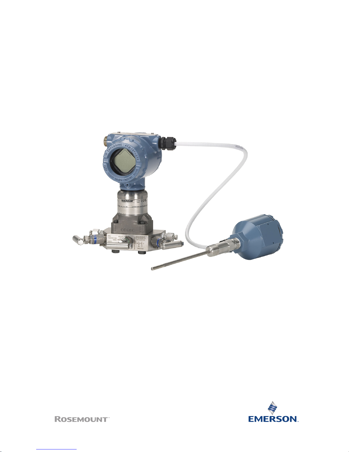
Quick Start Guide
00825-0100-4803, Rev EG
October 2018
Rosemount™ 3051S and 3051SF Series
Flow Meter MultiVariable™ Transmitters
Page 2

Safety messages
NOTICE
This guide provides basic guidelines for Rosemount™ 3051S MultiVariable™ Transmitter (3051SMV). It
also provides the basic Rosemount 3051SMV configuration guidelines for the Rosemount 3051SFA,
Rosemount 3051SFC, and Rosemount 3051SFP. It does not provide instructions for diagnostics,
maintenance, service, or troubleshooting. Refer to the Rosemount 3051SMV Reference Manual for
more instruction.This document is also available electronically on Emerson.com/Rosemount.
WARNING
Explosions could result in death or serious injury.
Installation of device in an explosive environment must be in accordance with appropriate local,
national, and international standards, codes, and practices.
Review Rosemount 3051SMV Reference Manual for any restrictions associated with a safe installation.
• Before connecting a handheld communicator in an explosive atmosphere, make sure the
instruments in the loop are installed in accordance with intrinsically safe or non-incendive field
wiring practices.
• In an explosion-proof/flameproof installation, do not remove the transmitter covers when power
is applied to the unit.
Process leaks could result in death or serious injury.
• Install and tighten process connectors before applying pressure.
Electrical shock could cause death or serious injury.
• Avoid contact with the leads and terminals. High voltage that may be present on leads can cause
electrical shock.
Conduit/cable entries
• Unless marked, the conduit/cable entries in the transmitter housing use a ½–14 NPT thread form.
Entries marked “M20” are M20 × 1.5 thread form. On devices with multiple conduit entries, all
entries will have the same thread form. Only use plugs, adapters, glands, or conduit with a
compatible thread form when closing these entries.
• When installing in a hazardous location, use only appropriately listed or Ex certified plugs, glands,
or adapters in cable/conduit entries.
Contents
Mount the transmitter .................................. 3
Consider housing rotation ............................ 9
Set the switches ......................................... 10
Connect wiring and power up ..................... 11
Engineering Assistant installation ............... 15
Flow configuration ..................................... 17
Verifying device configuration .................... 26
Trimming the transmitter ........................... 30
Safety instrumented systems installation ... 31
Product certifications ................................. 32
Quick Start Guide October 2018
2 Rosemount 3051SMV
Page 3
1 Mount the transmitter
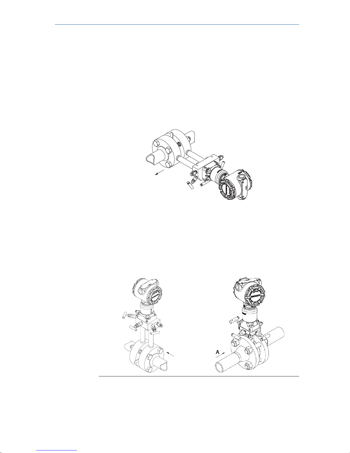
1.1 Liquid flow applications
Procedure
1. Place taps to the side of the line.
2. Mount beside or below the taps.
3. Mount the transmitter so that the drain/vent valves are oriented
upward.
A
A. Direction of flow
1.2 Gas flow applications
Procedure
1. Place taps in the top or side of the line.
2. Mount beside or above the taps.
A
A. Direction of flow
October 2018 Quick Start Guide
Quick Start Guide 3
Page 4
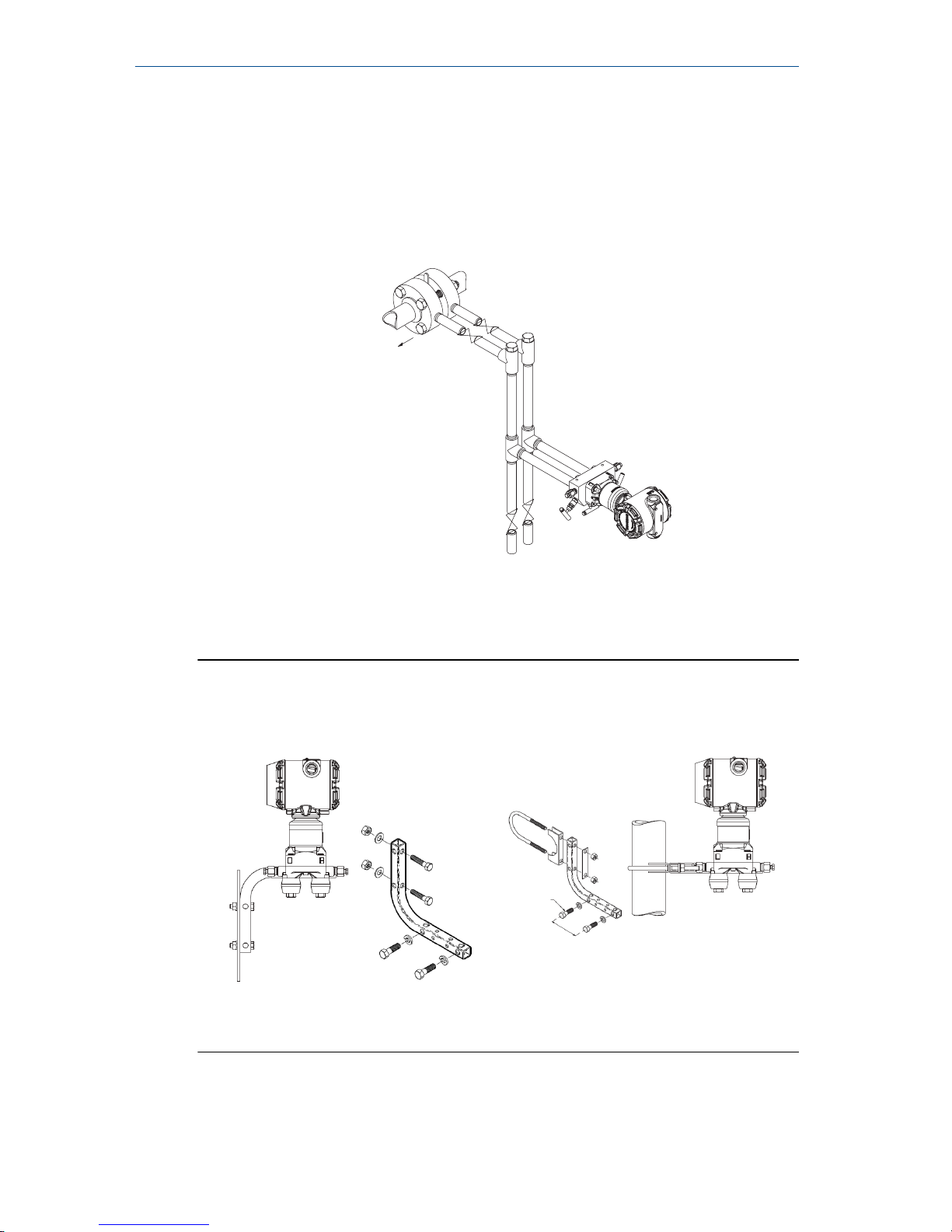
1.3 Steam flow applications
Procedure
1. Place taps to the side of the line.
2. Mount beside or below the taps.
3. Fill impulse lines with water.
A
A. Direction of flow
1.4 Mounting brackets
Figure 1-1: Mounting Bracket – Coplanar Flange
Panel mount
Pipe mount
Quick Start Guide October 2018
4 Rosemount 3051SMV
Page 5
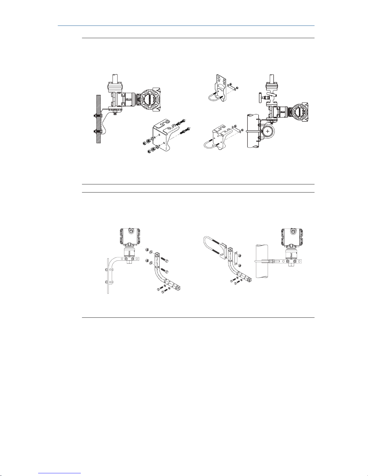
Figure 1-2: Mounting Brackets – Traditional Flange
Panel mount Pipe mount
Figure 1-3: Mounting Brackets – In-line
Panel mount Pipe mount
1.5 Bolting considerations
About this task
If the transmitter installation requires assembly of a process flange, manifold,
or flange adapters, follow these assembly guidelines to ensure a tight seal for
optimal performance characteristics of the transmitter. Only use bolts
supplied with the transmitter or sold by Emerson™ as spare parts. Figure 1-4
illustrates common transmitter assemblies with the bolt length required for
proper transmitter assembly.
October 2018 Quick Start Guide
Quick Start Guide 5
Page 6
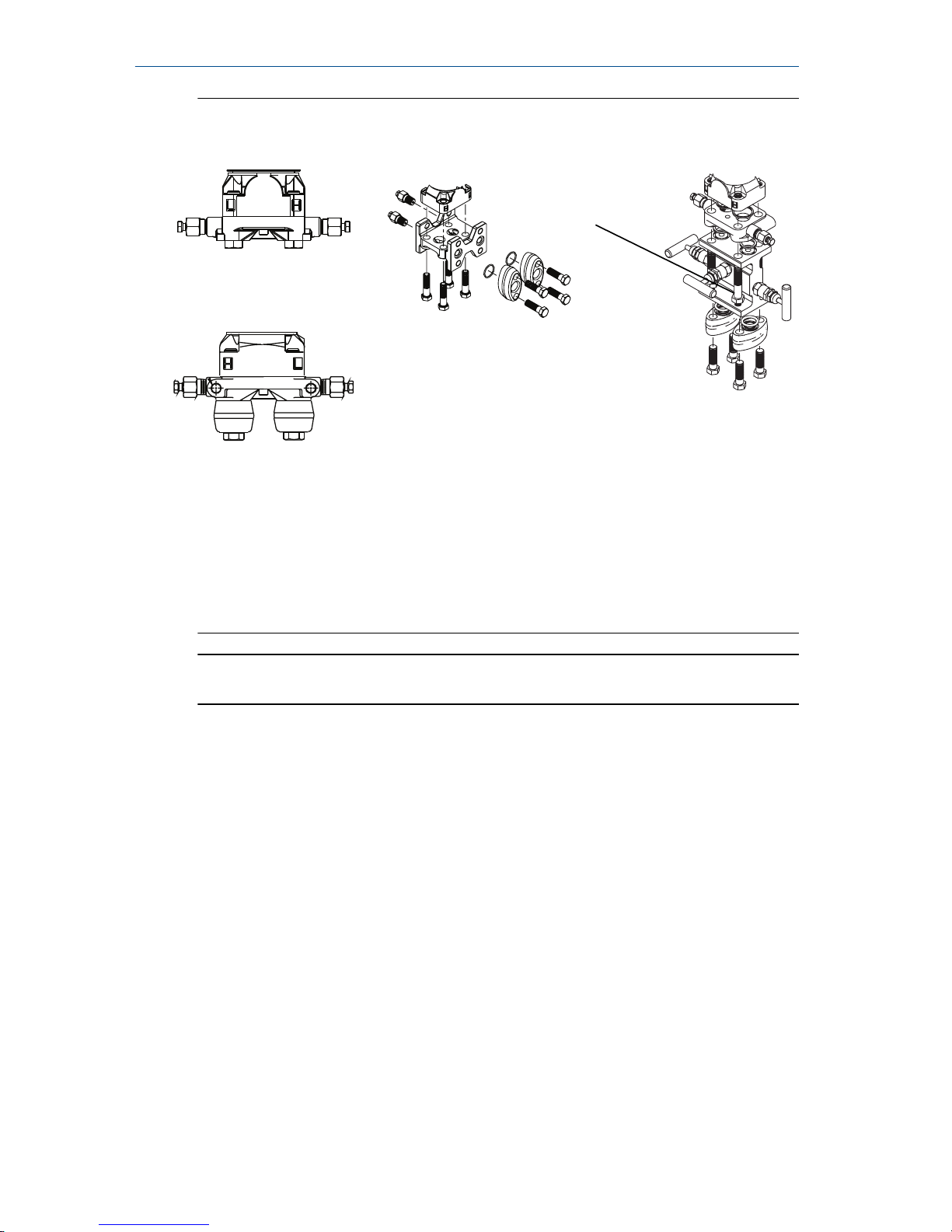
Figure 1-4: Common Transmitter Assemblies
A
4 × 1.75-in.
(44 mm)
D
4 × 1.75-in.
(44 mm)
4 × 2.25-in.
(57 mm)
C
4 × 1.75-in.
(44 mm)
4
× 1.50-in.
(38 mm)
B
4 × 2.88-in.
(73 mm)
A. Transmitter with coplanar flange
B. Transmitter with coplanar flange and optional flange adapters
C. Transmitter with traditional flange and optional flange adapters
D. Transmitter with coplanar flange and optional Rosemount Conventional
Manifold and flange adapters
Note
For all other manifolds, contact Customer Central technical support.
Bolts are typically carbon steel or stainless steel. Confirm the material by
viewing the markings on the head of the bolt and referencing Table 1-1 . If
bolt material is not shown in Table 1-1, contact the local Emerson
representative for more information.
Use the following bolt installation procedure:
Procedure
1. Carbon steel bolts do not require lubrication and the stainless steel
bolts are coated with a lubricant to ease installation. However, no
additional lubricant should be applied when installing either type of
bolt.
2. Finger-tighten the bolts.
3. Torque the bolts to the initial torque value using a crossing pattern.
See Table 1-1 for initial torque value.
4. Torque the bolts to the final torque value using the same crossing
pattern. See Table 1-1 for final torque value.
Quick Start Guide October 2018
6 Rosemount 3051SMV
Page 7
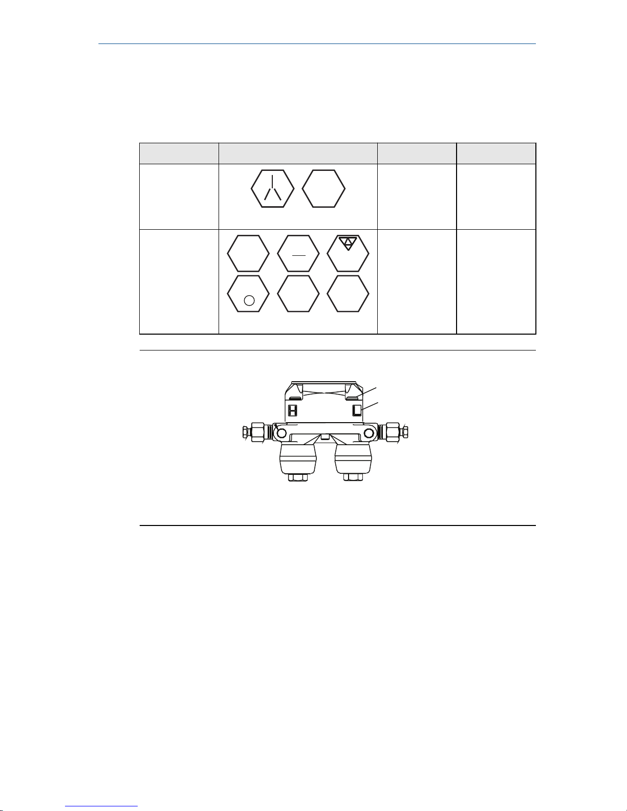
5. Verify the flange bolts are protruding through the sensor module
before applying pressure (see Figure 1-5).
Example
Table 1-1: Torque Values for the Flange and Flange Adapter Bolts
Bolt material Head markings Initial torque Final torque
Carbon Steel
(CS)
B7M
300 in-lb 650 in-lb
Stainless Steel
(SST)
316
316
316
SW
316
STM
316
R
B8M
150 in-lb 300 in-lb
Figure 1-5: Proper Bolt Installation
A
B
A. Bolt
B. Sensor module
October 2018 Quick Start Guide
Quick Start Guide 7
Page 8
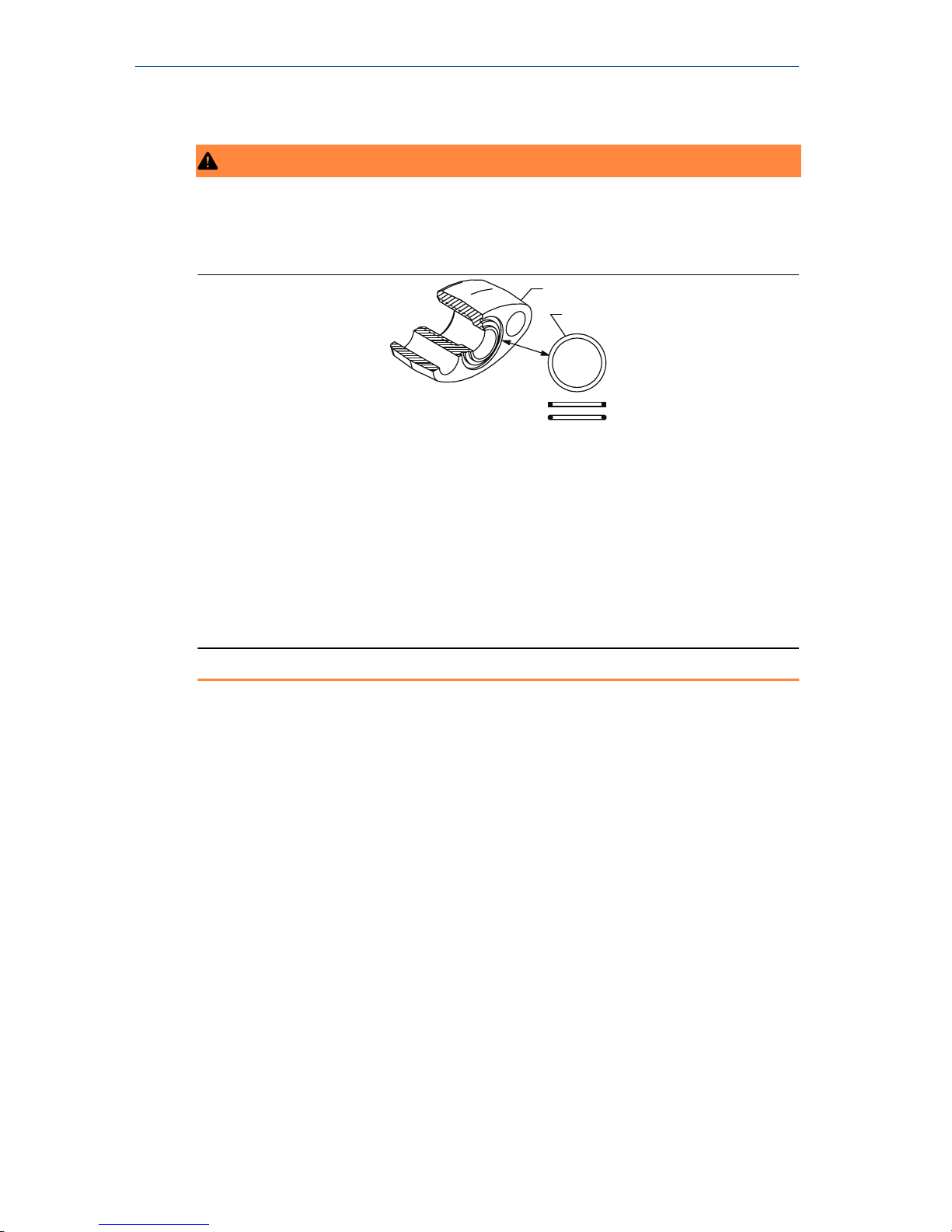
1.6 O-rings with flange adapters
WARNING
Failure to install proper flange adapter O-rings may cause process leaks, which
can result in death or serious injury. Only use the O-ring that is designed for its
specific flange adapter.
A
B
C
D
A. Flange adapter
B. O-ring
C. PTFE-based profile (square)
D. Elastomer profile (round)
Whenever the flange or adapters are removed, visually inspect the O-rings.
Replace them if there are any signs of damage, such as nicks or cuts. If the Orings are replaced, re-torque the flange bolts and alignment screws after
installation to compensate for seating of the O-rings.
Quick Start Guide October 2018
8 Rosemount 3051SMV
Page 9
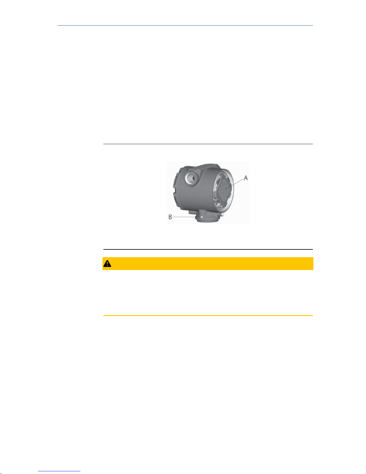
2 Consider housing rotation
About this task
To improve field access to wiring or to better view the optional LCD display:
Procedure
1. Loosen the housing rotation set screw.
2. Turn the housing up to 180° left or right of its original (as shipped)
position.
3. Re-tighten the housing rotation set screw.
Figure 2-1: Transmitter Housing Set Screw
A. LCD display
B. Housing rotation set screw (3/32-in.)
CAUTION
Do not rotate the housing more than 180° without first performing a
disassembly procedure (refer to Troubleshooting for more
information). Over-rotation may sever the electrical connection
between the sensor module and the electronics.
October 2018 Quick Start Guide
Quick Start Guide 9
Page 10
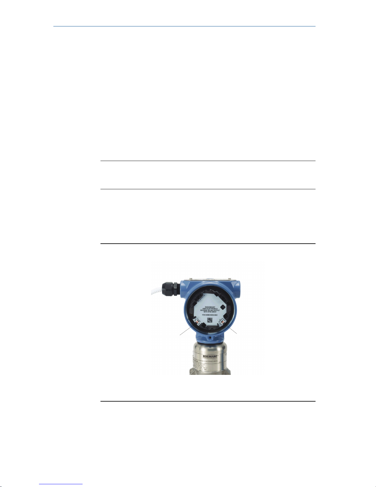
3 Set the switches
The transmitter’s default configuration sets the alarm condition to high (HI)
and the security to off.
Procedure
1. If the transmitter is installed, secure the bus and remove power.
2. Required: Remove the transmitter cover opposite the field terminal
side. Do not remove the instrument covers in explosive environments
when the circuit is live.
3. Slide the Security and Alarm switches into the preferred position by
using a small screwdriver.
Note
The Security switch will need to be in the off position in order to make
any configuration changes.
4. Required: In order to meet explosion-proof requirements, reinstall the
housing cover and tighten so the cover is fully seated with metal to
metal contact between the housing and cover. After the cover is
seated properly, replace the flathead screw located on the bottom of
the housing cover.
Figure 3-1: Transmitter Switch Configuration
A B
A. Security
B. AC Termination
Quick Start Guide October 2018
10 Rosemount 3051SMV
Page 11

4 Connect wiring and power up
About this task
CAUTION
Do not connect the power across the test terminals. Power could damage the
test diode in the test connection. Twisted pairs yield best results. Use 24 to 14
AWG wire and do not exceed 5,000 ft. (1500 m).
Use the following steps to wire the transmitter:
Procedure
1. Remove the cover on the field terminals side of the housing.
2. Connect the positive lead to the “PWR/COMM +” terminal, and the
negative lead to the “PWR/COMM –” terminal.
3. If the optional process temperature input is not installed, plug and seal
the unused conduit connection. If the input is being utilized, see Install
optional process temperature input (Pt 100 RTD sensor) for more
information.
NOTICE
When the enclosed pipe plug is utilized in the conduit opening, it must
be installed with a minimum engagement of five threads to comply
with explosion-proof requirements. Refer to the Rosemount
™
3051SMV Reference Manual for more information.
4. If applicable, install wiring with a drip loop. Arrange the drip loop
so the bottom is lower than the conduit connections and the
transmitter housing.
5. Reinstall the housing cover and tighten so that metal contacts metal
to meet explosion-proof requirements.
Figure 4-1 shows the wiring connections necessary to power a
Rosemount 3051SMV and enable communications with a hand-held
Field Communicator.
October 2018 Quick Start Guide
Quick Start Guide 11
Page 12
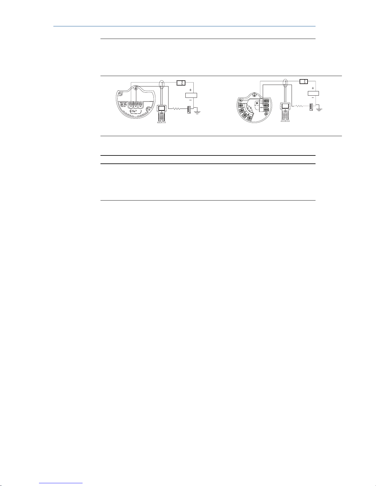
Figure 4-1: Transmitter Wiring
Without optional process temperature
connection
With optional process temperature
connection
A
RL ≥ 250Ω
A
RL ≥ 250Ω
A. Power supply
Note
Installation of the transient protection terminal block does not provide
transient protection unless the Rosemount 3051SMV housing is
properly grounded.
4.1 Conduit electrical connector wiring (option GE or GM)
For Rosemount™ 3051SMV with conduit electrical connectors GE or GM, refer
to the cordset manufacturer’s installation instructions for wiring details. For
FM Intrinsically Safe, Division 2 hazardous locations, install in accordance with
Rosemount drawing 03151-1009 to maintain outdoor rating (NEMA® 4X and
IP66). See the Rosemount 3051SMV Reference Manual.
4.2
Power supply
The dc power supply should provide power with less than two percent ripple.
The total resistance load is the sum of the resistance of the signal leads and
the load resistance of the controller, indicator, intrinsic safety barriers, and
related components.
Quick Start Guide October 2018
12 Rosemount 3051SMV
Page 13

Figure 4-2: Load Limitation
Maximum loop resistance = 43.5 x (power supply voltage – 12.0)
1322
1000
500
0
12.0 20 30
42.4
Voltage (Vdc)
Load (Ohms)
Operating
region
HART communication requires a minimum loop resistance of 250Ω
4.3 Install optional process temperature input (Pt 100 RTD
sensor)
About this task
Note
To meet ATEX/IECEx Flameproof certification, only ATEX/IECEx Flameproof
cables (temperature input code C30, C32, C33, or C34) may be used.
Procedure
1. Mount the Pt 100 RTD sensor in the appropriate location.
Note
Use shielded four-wire cable for the process temperature connection.
2. Connect the RTD cable to the Rosemount 3051SMV by inserting the
cable wires through the unused housing conduit and connect to the
four screws on the transmitter terminal block. An appropriate cable
gland should be used to seal the conduit opening around the cable.
3. Connect the RTD cable shield wire to the ground lug in the housing.
October 2018 Quick Start Guide
Quick Start Guide 13
Page 14
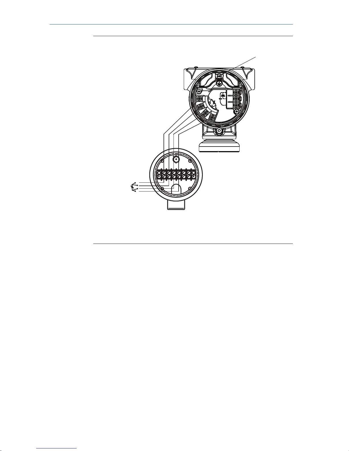
Figure 4-3: Rosemount 3051SMV RTD Wiring Connection
A
C
B
Red
Red
White
White
A. Ground lug
B. RTD cable assembly wires
C. Pt 100 RTD sensor
Quick Start Guide October 2018
14 Rosemount 3051SMV
Page 15

5 Engineering Assistant installation
Engineering Assistant 6.1 or later
The Rosemount™ 3051SMV Engineering Assistant 6.1 or later is PC-based
software that performs configuration, maintenance, diagnostic functions, and
serves as the primary communication interface to the Rosemount 3051SMV
with the fully compensated mass and energy flow feature board.
The Rosemount 3051SMV Engineering Assistant software is required to
complete the flow configuration.
NOTICE
To ensure correct operation, download the most current version of the
Engineering Assistant software at Emerson.com/Rosemount-Engineering-
Assistant.
5.1 System requirements
The following are the minimum system requirements to install the
Rosemount™ 3051SMV Engineering Assistant software:
• Pentium® -grade processor: 500 MHz or faster
• Operating system: Windows™ XP Professional (32-bit), or Windows 7 (32-
bit or 64-bit)
• 256 MB RAM
• 100 MB free hard disk space
• RS232 serial port or USB port (for use with HART® modem)
• CD-ROM
5.2
Install Rosemount 3051SMV Engineering Assistant 6.1 or
later
Procedure
1. Uninstall any existing versions of Engineering Assistant 6.
2. Insert the new Engineering Assistant disk into the CD-ROM.
3. Windows™ should detect the presence of a CD and start the
installation program. Follow the on-screen prompts to finish the
installation. If Windows does not detect the CD, use Windows Explorer
or My Computer to view the contents of the CD-ROM, and then double
click the SETUP.EXE program.
4. A series of screens (Installation Wizard) will appear and assist in the
installation process. Follow the on-screen prompts. It is recommended
to use the default installation settings.
October 2018 Quick Start Guide
Quick Start Guide 15
Page 16
Note
Engineering Assistant versions 6.1 or later require the use of
Microsoft®.NET Framework version 4.0 or later. If .NET version 4.0 is
not currently installed, the software will be automatically installed
during the Engineering Assistant installation. Microsoft .NET version
4.0 requires an additional 200 MB of disk space.
5.3 Connect to a personal computer
Procedure
1. Remove the cover from the field terminals side of the housing.
2. Power the device as outlined in Connect wiring and power up.
3. Connect the HART modem cable to the PC.
4. On the side of the transmitter marked “Field Terminals,” connect the
modem mini-grabbers to the two terminals marked “PWR/COMM.”
5. Launch the Engineering Assistant software. For more information on
launching software, see Launch Engineering Assistant 6.1 or later.
6. Once the configuration is complete, replace cover and tighten until
metal contacts metal to meet explosion-proof requirements.
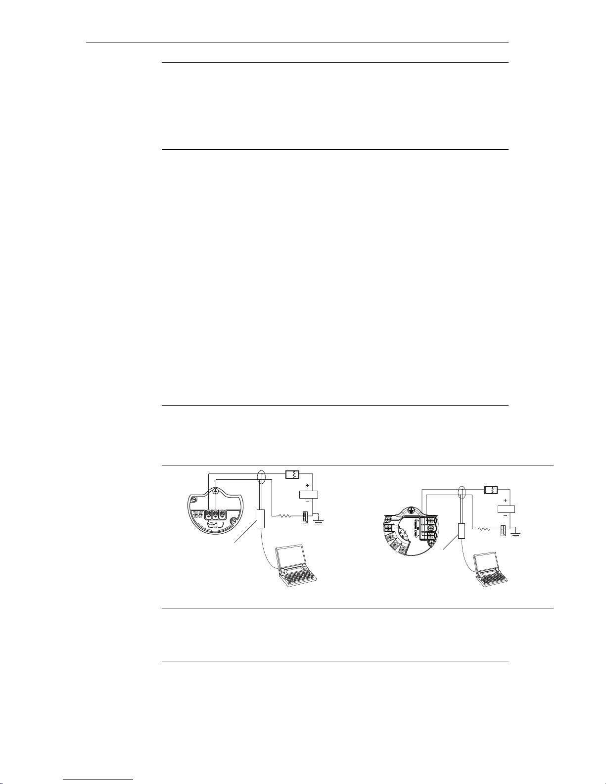
Figure 5-1 shows how to connect a computer to a Rosemount
3051SMV.
Figure 5-1: Connecting a PC to the Transmitter
Without optional process temperature
connection
With optional process temperature
connection
A
RL ≥ 250Ω
B
A
RL ≥ 250Ω
B
A. Power supply
B. Modem
Quick Start Guide October 2018
16 Rosemount 3051SMV
Page 17

6 Flow configuration
Rosemount™ 3051SMV Engineering Assistant 6.1 or later
The Rosemount 3051SMV Engineering Assistant is designed to guide the user
through the setup of the flow configuration for a Rosemount 3051SMV. The
flow configuration screens allow the user to specify the fluid, operating
conditions, and information about the primary element, including inside pipe
diameter. This information will be used by the Rosemount 3051SMV
Engineering Assistant software to create flow configuration parameters that
will be sent to the transmitter or saved for future use.
Online and offline modes
The Engineering Assistant software can be used in two modes: Online and
Offline. In Online mode, the user can receive the configuration from the
transmitter, edit the configuration, send the changed configuration to the
transmitter, or save the configuration to a file. In offline mode, the user can
create a new flow configuration and save the configuration to a file or open
and modify an existing file.
The following pages provide instructions on creating a new flow configuration
in offline mode. For more information on other functionality, see the
Rosemount 3051SMV Reference Manual.
October 2018 Quick Start Guide
Quick Start Guide 17
Page 18
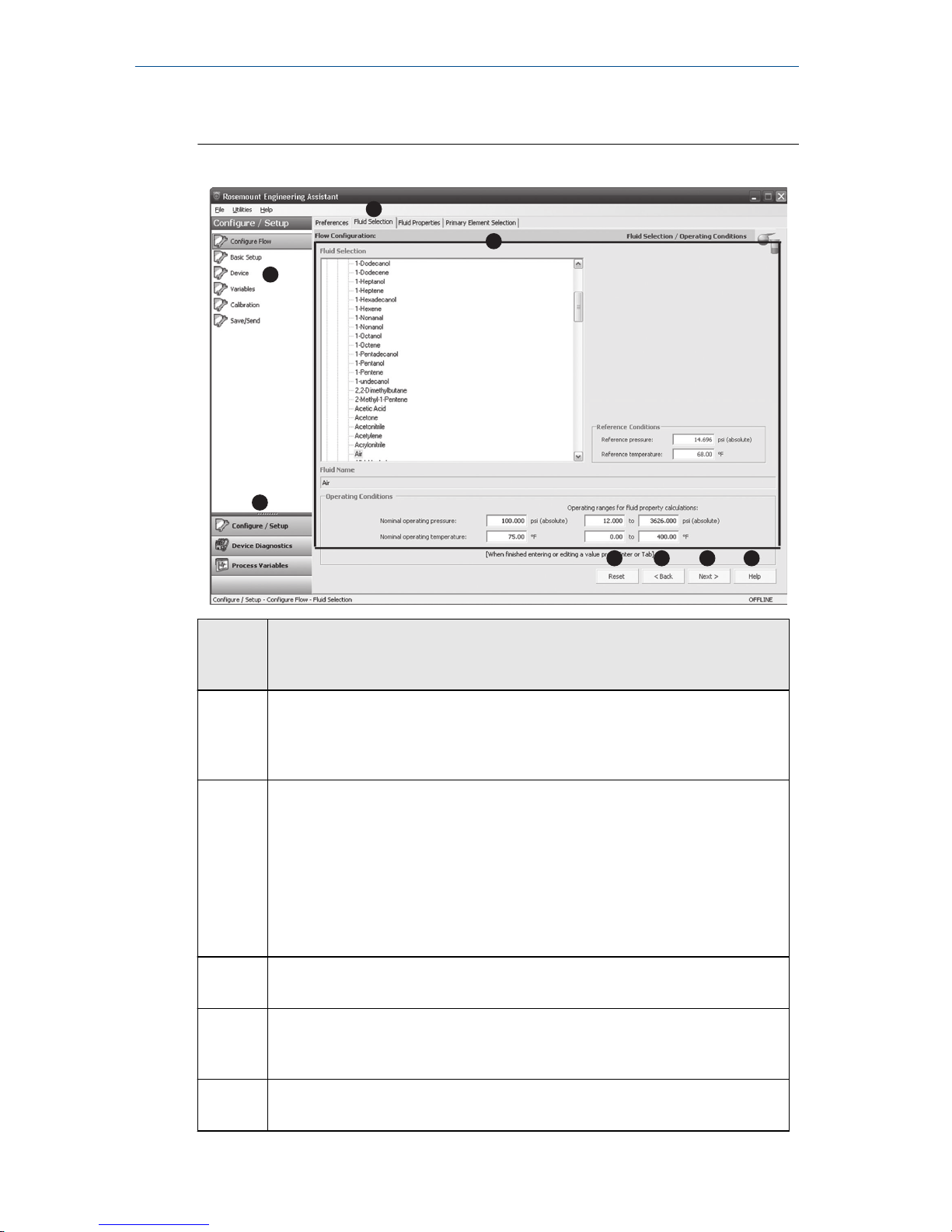
6.1 Basic navigation overview
Figure 6-1: Engineering Assistant Basic Navigation Overview
A
B C D E
G
H
F
Screen
compo
nent
Description of use
A The navigation tabs contain the flow configuration information. In Offline
mode, each tab will not become active until the required fields on the
previous tab are completed. In Online mode, these tabs will be functional
at all times.
B The Reset button will return each field within all of the flow configuration
tabs (Fluid Selection, Fluid Properties, and Primary Element Selection) to
the values initially displayed at the start of the configuration.
• In Online mode, the values will return to the initial values received
from the device before the start of the configuration.
• If editing a previously saved flow configuration, the values will return
to those that were last saved. If starting a new flow configuration, all
entered values will be erased.
C The Back button is used to step backward through the flow configuration
tabs.
D The Next button is used to step forward through the flow configuration
tabs. In Offline mode, the Next button will not become active until all
required fields on the current page are completed.
E The Help button can be clicked at any time to get a detailed explanation
of the information that is required on the current configuration tab.
Quick Start Guide October 2018
18 Rosemount 3051SMV
Page 19
Screen
compo
nent
Description of use
F Any configuration information that needs to be entered or reviewed will
appear in this portion of the screen.
G These menus navigate to the Configure Flow, Basic Setup, Device,
Variables, Calibration, and Save/Send Configuration tabs.
H These buttons navigate to Config/Setup, Device Diagnostics or Process
Variables sections.
6.2 Launch Engineering Assistant 6.1 or later
About this task
Flow configuration for the Rosemount 3051SMV is achieved by launching the
Engineering Assistant software from the Start menu.
Procedure
1. Select the Start menu > All Programs > Engineering Assistant.
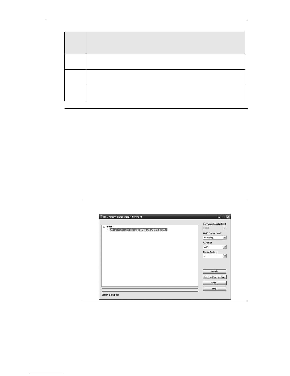
Engineering Assistant will open to the screen shown in Figure 6-2.
2. Select Offline button located in the lower right hand corner of the
screen shown in Figure 6-2.
Figure 6-2: Engineering Assistant Device Connection Screen
October 2018 Quick Start Guide
Quick Start Guide 19
Page 20
6.3 Use Preferences tab
About this task
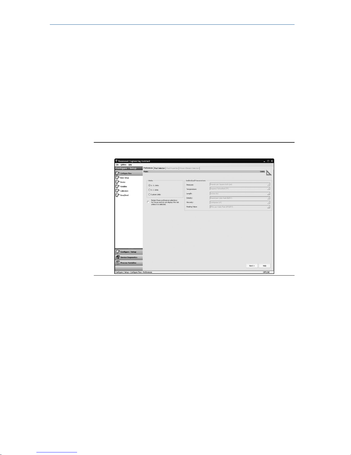
The Preferences tab, shown in Figure 6-3, allows you to select the preferred
engineering units to display.
Procedure
1. Select the preferred engineering units.
2. If Custom Units are selected, configure the Individual Parameters.
3. Check the box if unit preferences should be retained for future
Engineering Assistant sessions.
Figure 6-3: Preferences Tab
6.4 Select fluid for database liquid/gas
About this task
The Fluid Selection tab shown in Figure 6-4 allows the user to choose the
process fluid.
Quick Start Guide October 2018
20 Rosemount 3051SMV
Page 21
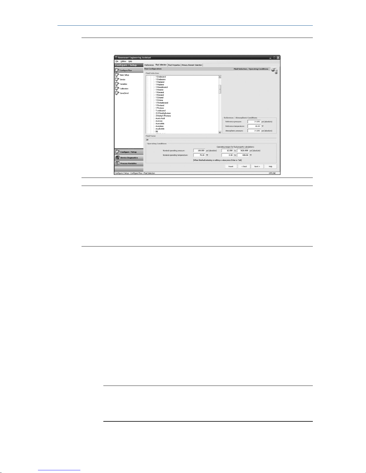
Figure 6-4: Fluid Selection Tab
Note
The following example will show a flow configuration for the database gas air
used with a Rosemount 405C Conditioning Orifice Plate as the primary
element. The procedure to set up any other fluid with any other primary
element will be similar to this example. Natural gases, custom liquids, and
custom gases require additional steps during the configuration. See the
Rosemount 3051SMV Reference Manual for more information.
Procedure
1. Engineering Assistant may open to the Preferences tab. Using the tabs
at the top of the screen, navigate to the Fluid Selection tab.
2. Expand the Gas category (click on the + icon).
3. Expand the Database Gas category.
4. Select Air from the list of database fluids.
5. Enter the Nominal Operating Pressure, select the Enter or Tab key.
6. Enter the Nominal Operating Temperature, select the Enter or Tab key.
Engineering Assistant will automatically fill in suggested operating
ranges, as shown in Figure 6-4. These values may be edited as needed
by the user.
7. Verify the Reference/Atmospheric Conditions are correct for the
application. These values may be edited as needed.
Note
Reference pressure and temperature values are used by Engineering
Assistant to convert the flow rate from mass units to mass units
expressed as standard or normal volumetric units.
October 2018 Quick Start Guide
Quick Start Guide 21
Page 22
8. Select Next to proceed to the Fluid Properties tab.
6.5 Fluid properties
Note
The Fluid Properties tab is an optional step and is not required to complete a
flow configuration.
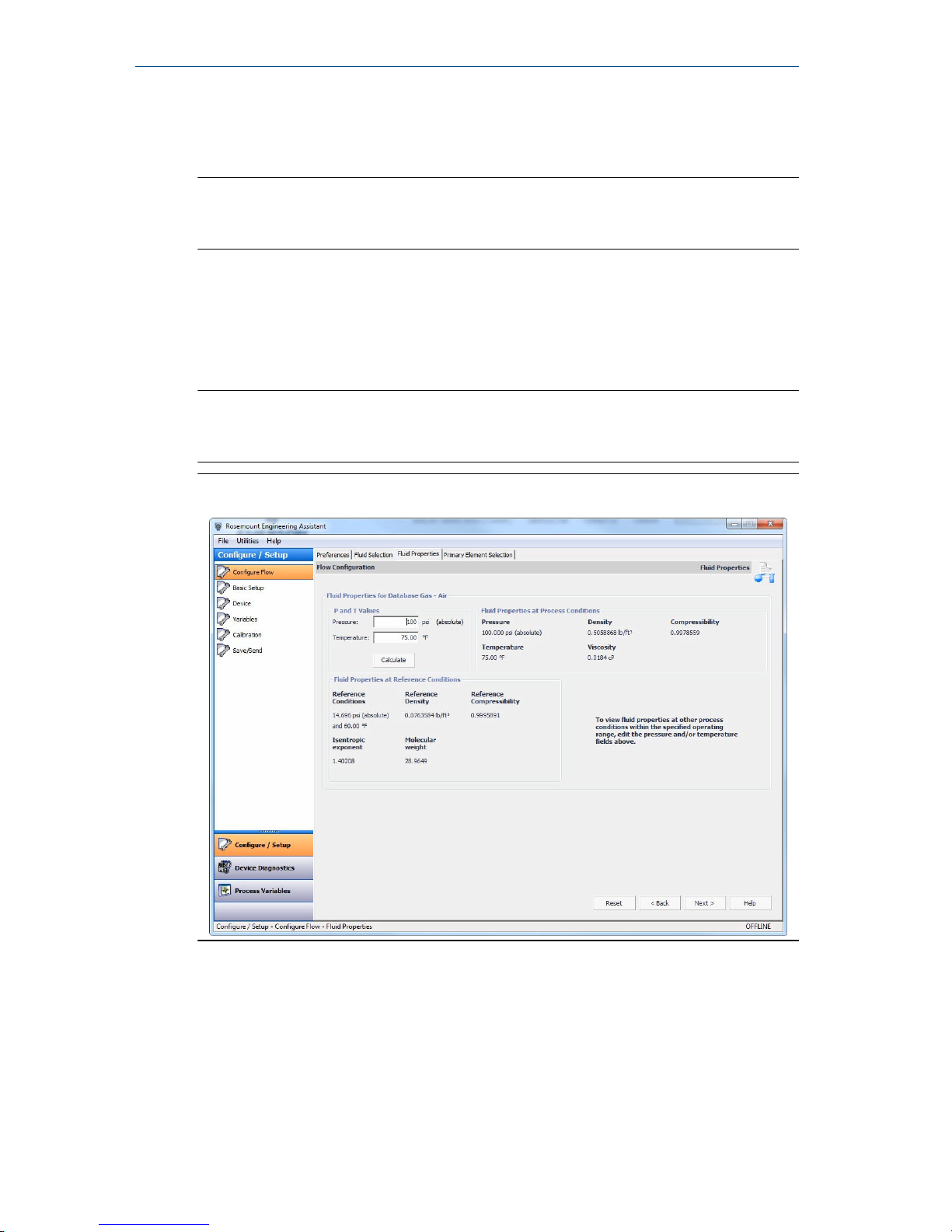
The Fluid Properties tab for the database gas air is shown in Figure 6-5. This is
used to verify the properties of the chosen fluid are acceptable.
To check density, compressibility, and viscosity of the selected fluid at other
pressure and temperature values, enter a Pressure and Temperature and
select Calculate.
Note
Changing the pressure and temperature values on the Fluid Properties tab does
not affect the fluid configuration.
Figure 6-5: Fluid Properties Tab
6.6 Select primary element
About this task
The Primary Element Selection tab shown in Figure 6-6 allows the user to
choose the primary element.
Quick Start Guide October 2018
22 Rosemount 3051SMV
Page 23
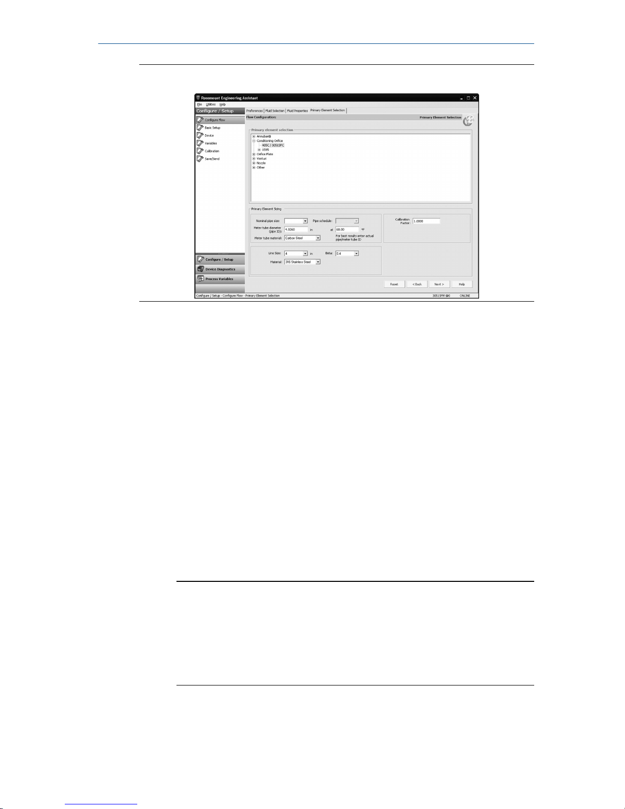
Figure 6-6: Primary Element Selection Tab
Continuing with the example configuration:
Procedure
1. Expand the Conditioning Orifice Plate category.
2. Select 405C/3051SFC.
3. Enter the measured Meter Tube Diameter (pipe ID) at a reference
temperature. If the meter tube diameter cannot be measured, select a
Nominal Pipe Size and Pipe Schedule to input an estimated value for
the meter tube diameter (English units only).
4. If necessary, edit the Meter Tube Material.
5. Enter the Line Size and select the Beta of the conditioning orifice
plate. The required primary element sizing parameters will be different
depending on what primary element was selected.
6. If necessary, select a primary element Material from the dropdown
menu.
7. Select Next > to advance to the Save/Send Configuration tab.
Note
To be in compliance with appropriate national or international
standards, beta ratios and differential producer diameters should be
within the limits as listed in the applicable standards. The Engineering
Assistant software will alert the user if a primary element value
exceeds these limits, but will allow the user to proceed with the flow
configuration.
October 2018 Quick Start Guide
Quick Start Guide 23
Page 24
6.7 Save/send configuration
About this task
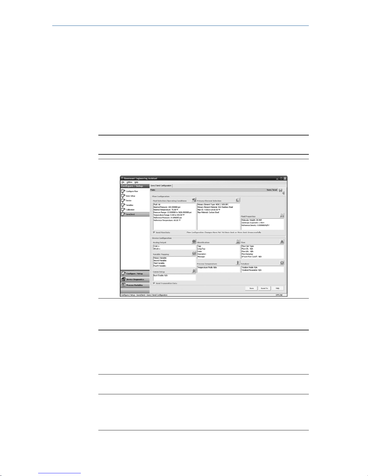
The Save/Send Configuration tab shown in Figure 6-7 allows you to verify, save,
and send the configuration information to the transmitter with the fully
compensated mass and energy flow feature board.
Procedure
1. Review the information under the Flow Configuration and Device
Configuration headings.
Note
For more information, see Verifying device configuration.
Figure 6-7: Save/Send Configuration Tab
2. Select the icon above each window to edit the configuration
information in these windows.
Note
The user will be notified if the configuration has been modified since it
was last sent to the transmitter. A warning message will be shown to
the right of the Send Flow Data and/or Send Transmitter Data check
boxes.
3. To send the configuration, select the Send To button.
Note
The Send Flow Data and Send Transmitter Data check boxes can be used
to select what configuration data is sent to the transmitter. If either
check box is unselected, the corresponding data will not be sent.
Quick Start Guide October 2018
24 Rosemount 3051SMV
Page 25
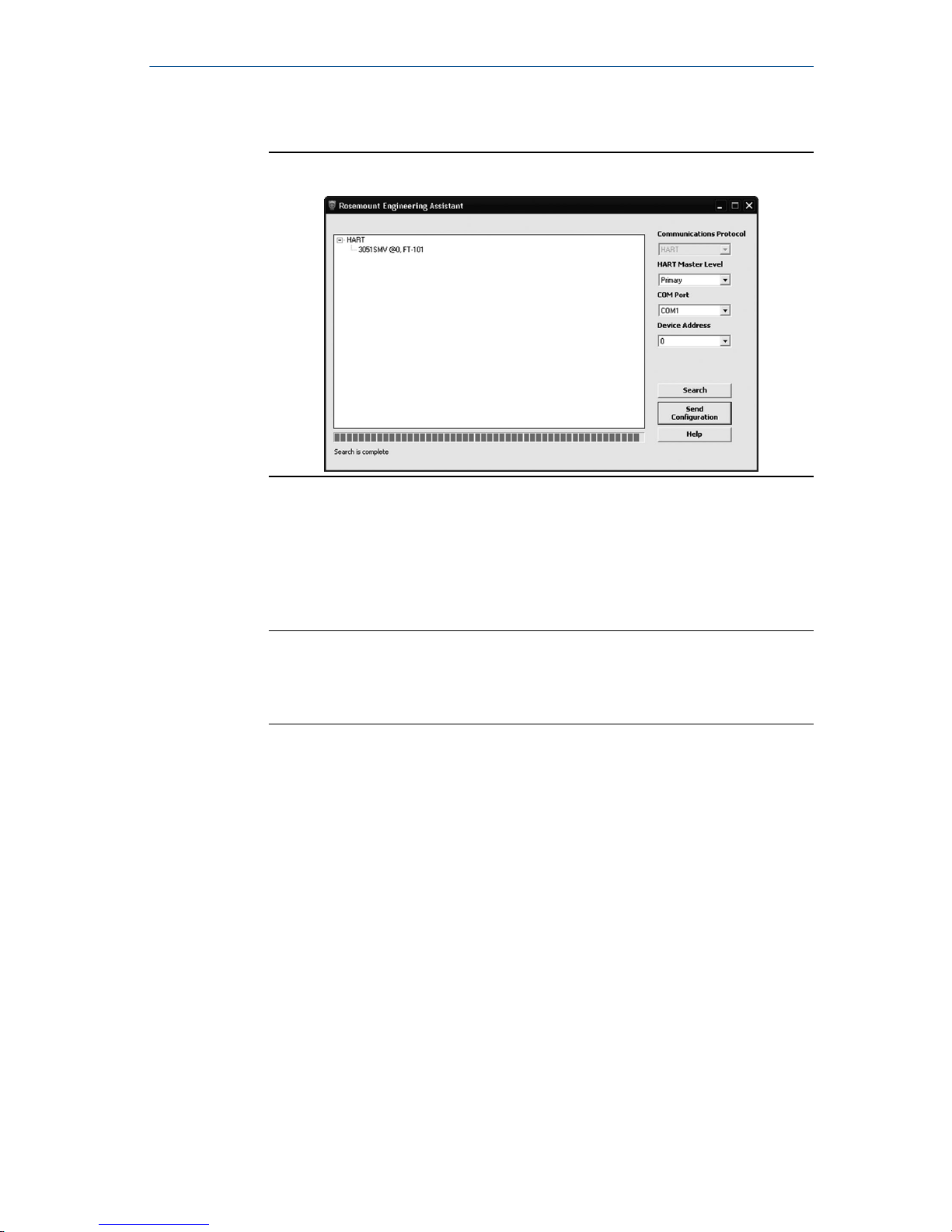
4. The Engineering Assistant Device Connection screen will appear, see
Figure 6-8.
Figure 6-8: Engineering Assistant Device Connection Screen
5. Select the Search button located in the lower right hand corner of the
screen. Engineering Assistant will begin to search for connected
devices.
6. When the search is completed, select the device to communicate with
and select Send Configuration button.
Note
After the configuration is sent to the device, saving the configuration
file is recommended. The user can select the Save button on the Save/
Send screen or select Save from the program menu.
Once the configuration is finished being sent to the device, the user
will be notified by a pop-up dialog box.
7. If finished with the configuration process, close Engineering Assistant.
October 2018 Quick Start Guide
Quick Start Guide 25
Page 26

7 Verifying device configuration
Use Rosemount™ 3051SMV Engineering Assistant or any HART® -compliant
master to communicate with and verify configuration of the Rosemount
3051SMV.
Table 7-1 shows the Field Communicator fast keys for the fully compensated
mass and energy flow. Table 7-2 shows the Fast Keys for the direct process
variable output.
Note
Device configuration procedures are given for Rosemount 3051SMV
Engineering Assistant 6.1 or later and AMS Device Manager 9.0 or later in the
Rosemount 3051SMV Reference Manual.
A check (✓) indicates the basic configuration parameters. At a minimum,
these parameters should be verified as part of the configuration and startup
procedure.
Table 7-1: Fast Keys for Fully Compensated Mass and Energy Flow
Function Fast Key
sequence
Absolute Pressure Reading and Status 1, 4, 2, 1, 5
Absolute Pressure Sensor Limits 1, 4, 1, 5, 8
Absolute Pressure Units 1, 3, 3, 5
Alarm and Saturation Level Configuration 1, 4, 2, 6, 6
Alarm and Saturation Levels 1, 4, 2, 6
Analog Output Trim Options 1, 2, 5, 2
Burst Mode Setup 1, 4, 3, 3, 3
Burst Mode Options 1, 4, 3, 3, 4
Callendar-van Dusen Sensor Matching 1, 2, 5, 5, 4
Configure Fixed Variables 1, 2, 4
✓ Damping 1, 3, 7
Diaphragm Seals Information 1, 4, 4, 5
✓ Differential Pressure Low Flow Cutoff 1, 4, 1, 1, 6
Differential Pressure Reading and Status 1, 4, 2, 1, 4
Differential Pressure Sensor Trim Options 1, 2, 5, 3
✓ Differential Pressure Zero Trim 1, 2, 5, 3, 1
Differential Pressure Units 1, 3, 3, 4
Quick Start Guide October 2018
26 Rosemount 3051SMV
Page 27

Table 7-1: Fast Keys for Fully Compensated Mass and Energy Flow
(continued)
Function Fast Key
sequence
Energy Rate Units 1, 3, 3, 2
Energy Reading and Status 1, 4, 2, 1, 2
Equipped Sensors 1, 4, 4, 4
Field Device Information 1, 4, 4, 1
Flow Calculation Type 1, 4, 1, 1, 2
✓ Flow Rate Units 1, 3, 3, 1
Flow Reading and Status 1, 4, 2, 1, 1
Gage Pressure Reading and Status 1, 4, 2, 1, 6
Gage Pressure Sensor Limits 1, 4, 1, 5, 9
Gage Pressure Units 1, 3, 3, 6
LCD Configuration 1, 3, 8
Loop Test 1, 2, 2
Module Temperature Reading and Status 1, 4, 2, 1, 8
Module Temperature Units 1, 3, 3, 8
Poll Address 1, 4, 3, 3, 1
Process Temperature Reading and Status 1, 4, 2, 1, 7
✓ Process Temperature Sensor Mode 1, 4, 1, 6, 8
Process Temperature Sensor Trim Options 1, 2, 5, 5
Process Temperature Unit 1, 3, 3, 7
✓ Ranging the Analog Output 1, 2, 5, 1
Recall Factory Trim Settings 1, 2, 5, 2, 3
Sensor Information 1, 4, 4, 2
Static Pressure Sensor Lower Trim (AP Sensor) 1, 2, 5, 4, 2
Static Pressure Sensor Trim Options 1, 2, 5, 4
Static Pressure Sensor Zero Trim (GP Sensor) 1, 2, 5, 4, 1
Status 1, 2, 1
✓ Tag 1, 3, 1
Test Flow Calculation 1, 2, 3
October 2018 Quick Start Guide
Quick Start Guide 27
Page 28
Table 7-1: Fast Keys for Fully Compensated Mass and Energy Flow
(continued)
Function Fast Key
sequence
Totalizer Configuration 1, 4, 1, 3
Totalizer Reading and Status 1, 4, 2, 1, 3
Totalizer Units 1, 3, 3, 3
Variable Mapping 1, 4, 3, 4
Write Protect 1, 3, 5, 4
Table 7-2: Fast Keys for Direct Process Variable Output
Function Fast Key
sequence
Absolute Pressure Reading and Status 1, 4, 2, 1, 2
Absolute Pressure Sensor Limits 1, 4, 1, 2, 8
Absolute Pressure Units 1, 3, 3, 2
Alarm and Saturation Level Configuration 1, 4, 2, 6, 6
Alarm and Saturation Levels 1, 4, 2, 6
Analog Output Trim Options 1, 2, 4, 2
Burst Mode Setup 1, 4, 3, 3, 3
Burst Mode Options 1, 4, 3, 3, 4
Callendar-van Dusen Sensor Matching 1, 2, 4, 5, 4
✓ Damping 1, 3, 7
Diaphragm Seals Information 1, 4, 4, 4
Differential Pressure Reading and Status 1, 4, 2, 1, 1
Differential Pressure Sensor Trim Options 1, 2, 4, 3
✓ Differential Pressure Zero Trim 1, 2, 4, 3, 1
✓ Differential Pressure Units 1, 3, 3, 1
Equipped Sensors 1, 4, 4, 3
Field Device Information 1, 4, 4, 1
Gage Pressure Reading and Status 1, 4, 2, 1, 3
Gage Pressure Sensor Limits 1, 4, 1, 2, 9
Gage Pressure Units 1, 3, 3, 3
Quick Start Guide October 2018
28 Rosemount 3051SMV
Page 29

Table 7-2: Fast Keys for Direct Process Variable Output (continued)
Function Fast Key
sequence
LCD Configuration 1, 3, 8
Loop Test 1, 2, 2
Module Temperature Reading and Status 1, 4, 2, 1, 5
Module Temperature Units 1, 3, 3, 5
Poll Address 1, 4, 3, 3, 1
Process Temperature Reading and Status 1, 4, 2, 1, 4
Process Temperature Sensor Trim Options 1, 2, 4, 5
Process Temperature Unit 1, 3, 3, 4
✓ Ranging the Analog Output 1, 2, 4, 1
Recall Factory Trim Settings 1, 2, 4, 2, 3
Sensor Information 1, 4, 4, 2
Static Pressure Sensor Lower Trim (AP Sensor) 1, 2, 4, 4, 2
Static Pressure Sensor Trim Options 1, 2, 4, 4
Static Pressure Sensor Zero Trim (GP Sensor) 1, 2, 4, 4,1
Status 1, 2, 1
✓ Tag 1, 3, 1
✓ Transfer Function 1, 3, 6
Variable Mapping 1, 4, 3, 4
Write Protect 1, 3, 5, 4
October 2018 Quick Start Guide
Quick Start Guide 29
Page 30

8 Trimming the transmitter
Transmitters are shipped fully calibrated per request or by the factory default
of full scale.
8.1 Zero trim
A zero trim is a single-point adjustment used for compensating mounting
position and line pressure effects on static and differential pressure sensors.
When performing a zero trim, ensure that the equalizing valve is open and all
wet legs are filled to the correct level.
The transmitter will only allow up to five percent of URL zero error to be
trimmed.
8.1.1 Perform a zero trim using the Field Communicator
Procedure
1. Equalize or vent the transmitter and connect the Field Communicator
(for more information on connecting the Field Communicator, see
Figure 4-1).
2. If the device is equipped with a static pressure sensor, zero the sensor
by inputting the following Fast Key sequence at the Rosemount
™
3051SMV menu:
Flow Fast
Keys
Direct output
Fast Keys
Description
1, 2, 5, 4 1, 2, 4, 4 Static pressure sensor trim options
3. Use the zero trim (selection 1) for a transmitter equipped with a gage
static pressure sensor or lower sensor trim (selection 2) for a
transmitted equipped with an absolute static pressure sensor.
Note
When performing a lower sensor trim on an absolute pressure sensor,
it is possible to degrade the performance of the sensor if inaccurate
calibration equipment is used. Use a barometer that is at least three
times as accurate as the absolute sensor of the transmitter.
4. Zero the differential pressure sensor by inputting the following Fast
Key sequence at the Rosemount 3051SMV menu:
Flow Fast
Keys
Direct output
Fast Keys
Description
1, 2, 5, 3, 1 1, 2, 4, 3, 1 Differential pressure sensor zero trim
Quick Start Guide October 2018
30 Rosemount 3051SMV
Page 31

9 Safety instrumented systems installation
For safety certified installations, refer to the appropriate reference manual for
the installation procedure and system requirements:
• For DP only measurements (measurement type D) refer to the Rosemount
3051S Reference Manual.
• For MultiVariable measurements (measurement type 1–7) refer to the
Rosemount 3051SMV Reference Manual.
October 2018 Quick Start Guide
Quick Start Guide 31
Page 32

10 Product certifications
10.1 Rosemount 3051SMV/3051SFx Product Certifications
Rev 2.0
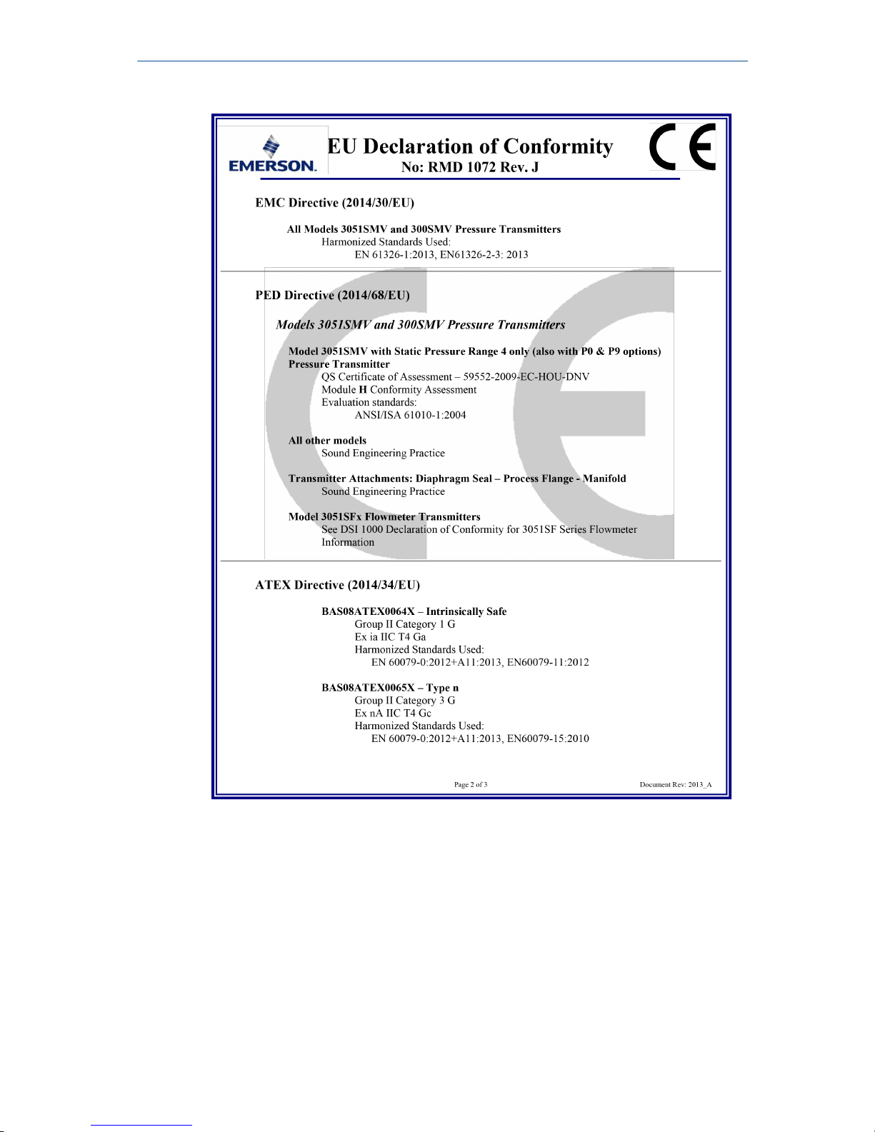
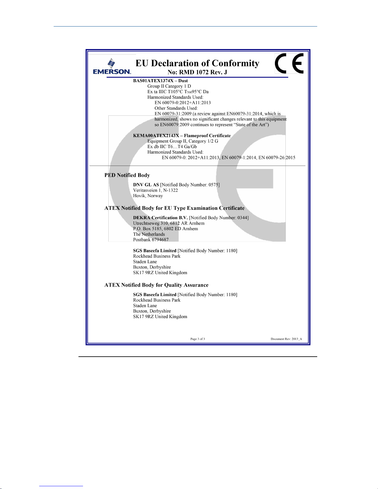
European Directive Information
A copy of the EU Declaration of Conformity can be found at the end of the
Quick Start Guide. The most recent revision of the EU Declaration of
Conformity can be found at Emerson.com/Rosemount.
Ordinary Location Certification
As standard, the transmitter has been examined and tested to determine that
the design meets the basic electrical, mechanical, and fire protection
requirements by a nationally recognized test laboratory (NRTL) as accredited
by the Federal Occupational Safety and Health Administration (OSHA).
Installing Equipment in North America
The US National Electrical Code® (NEC) and the Canadian Electrical Code (CEC)
permit the use of Division marked equipment in Zones and Zone marked
equipment in Divisions. The markings must be suitable for the area
classification, gas, and temperature class. This information is clearly defined in
the respective codes.
10.1.1 USA
E5 US Explosionproof (XP) and Dust-Ignitionproof (DIP)
Certificate
FM16US0089X
Standards
FM Class 3600 – 2011, FM Class 3615 – 2006, FM Class 3616 –
2011, 3810 – 2005,ANSI/NEMA 250 – 2003
Markings
XP CL I, DIV 1, GP B, C, D; T5; DIP CL II, DIV 1,GP E, F, G; CL III;
T5(–50 °C ≤ Ta ≤ +85 °C); Factory Sealed; Type 4X
I5 US Intrinsically Safe (IS) and Nonincendive (NI)
Certificate
FM16US0233
Standards
FM Class 3600 – 2011, FM Class 3610 – 2007, FM Class 3611 –
2004, FM Class 3810 – 2005, NEMA 250 – 1991
Markings
IS CL I, DIV 1, GP A, B, C, D; CL II, DIV 1, GP E, F, G; Class III; Class
1, Zone 0 AEx ia IIC T4; NI CL 1, DIV 2, GP A, B, C, D; T4(–50 °C≤ T
a
≤ +70 °C) when connected per Rosemount drawing 03151-1206;
Type 4X
Quick Start Guide October 2018
32 Rosemount 3051SMV
Page 33

Note
Transmitters marked with NI CL 1, DIV 2 can be installed in Division 2 locations
using general Division 2 wiring methods or Nonincendive Field Wiring (NIFW).
See Drawing 03151-1206.
IE US FISCO Intrinsically Safe
Certificate
FM16US0233
Standards
FM Class 3600 – 2011, FM Class 3610 – 2010, FM Class 3611 –
2004, FM Class 3616 – 2006, FM Class 3810 – 2005, NEMA 250
– 1991
Markings
IS CL I, DIV 1, GP A, B, C, D;
Standards
T4(–50 °C ≤ Ta ≤ +70 °C); when connected per Rosemount
drawing 03151-1006; Type 4X
10.1.2 Canada
E6 Canada Explosionproof, Dust Ignition-proof, Division 2
Certificate
1143113
Standards
CAN/CSA C22.2 No. 0-10, CSA Std C22.2 No. 25-1966, CSA Std
C22.2 No. 30-M1986, CSA C22.2 No. 94.2-07, CSA Std C22.2
No. 213-M1987, CAN/CSA C22.2 60079-11:14, CAN/CSA-C22.2
No. 61010-1-12, ANSI/ISA 12.27.01-2003, CSA Std C22.2 No.
60529:05 (R2010)
Markings
Explosionproof Class I, Division 1, Groups B, C, D; DustIgnitionproof Class II, Division 1, Groups E, F, G; Class III; suitable
for Class I, Division 2, Groups A, B, C, D; Type 4X
I6 Canada Intrinsically Safe
Certificate
1143113
Standards
CAN/CSA C22.2 No. 0-10, CSA Std C22.2 No. 25-1966, CSA Std
C22.2 No. 30-M1986, CSA C22.2 No. 94.2-07, CSA Std C22.2
No. 213-M1987, CAN/CSA C22.2 60079-11:14, CAN/CSA-C22.2
No. 61010-1-12, ANSI/ISA 12.27.01-2003, CSA Std C22.2 No.
60529:05 (R2010)
Markings
Intrinsically Safe Class I, Division 1; suitable for Class 1, Zone 0,
IIC, T3C, Ta = 70 °C; when connected per Rosemount drawing
03151-1207; Type 4X
IF Canada FISCO Intrinsically Safe
Certificate
1143113
October 2018 Quick Start Guide
Quick Start Guide 33
Page 34
Standards
CAN/CSA C22.2 No. 0-10, CSA Std C22.2 No. 25-1966, CSA Std
C22.2 No. 30-M1986, CSA C22.2 No. 94.2-07, CSA Std C22.2
No. 213-M1987, CAN/CSA C22.2 60079-11:14, CAN/CSA-C22.2
No. 61010-1-12, ANSI/ISA 12.27.01-2003, CSA Std C22.2 No.
60529:05 (R2010)
Markings
FISCO Intrinsically Safe Class I, Division 1; Groups A, B, C, D;
suitable for Class I, Zone 0; T3C, Ta = 70 °C; when installed per
Rosemount drawing 03151-1207; Type 4X
10.1.3 Europe
E1 ATEX Flameproof
Certificate
KEMA 00ATEX2143X
Standards
EN 60079-0:2012+A11:2013, EN 60079-1: 2014, EN
60079-26:2015
Markings
II 1/2 G Ex db IIC T6…T4 Ga/Gb, T6(–60 °C ≤ Ta ≤ +70 °C), T5/
T4(–60 °C ≤ Ta ≤ +80 °C)
Temperature class Process temperature
T6 –60 °C to +70 °C
T5 –60 °C to +80 °C
T4 –60 °C to +120 °C
Special Conditions for Safe Use (X):
1. This device contains a thin wall diaphragm less than 1 mm thickness
that forms a boundary between Category 1 (process connection) and
Category 2 (all other parts of the equipment). The model code and
datasheet are to be consulted for details of the diaphragm material.
Installation, maintenance, and use shall take into account the
environmental conditions to which the diaphragm will be subjected.
The manufacturer's instructions for installation and maintenance shall
be followed in detail to assure safety during its expected lifetime.
2. Flameproof joints are not intended for repair.
3. Non-standard paint options may cause risk from electrostatic
discharge. Avoid installations that could cause electrostatic build-up
on painted surfaces, and only clean the painted surfaces with a damp
cloth. If paint is ordered through a special option code, contact the
manufacturer for more information.
4. Appropriate cable, glands, and plugs need to be suitable for a
temperature of 5 °C greater than maximum specified temperature for
location where installed.
Quick Start Guide October 2018
34 Rosemount 3051SMV
Page 35
I1 ATEX Intrinsic Safety
Certificate
Baseefa08ATEX0064X
Standards
EN 60079-0:2012, EN 60079-11:2012
Markings
II 1 G Ex ia IIC T4 Ga, T4(–60 °C ≤Ta ≤ +70 °C)
Parameter HART®FOUNDATION
Fieldbus
SuperModule
™
only
RTD (for 3051SFx)
HART Fieldbus
Voltage U
i
30 V 30 V 7.14 V 30 V 30 V
Current I
i
300
mA
300 mA 300 mA 2.31 mA 18.24 mA
Power P
i
1 W 1.3 W 887 mW 17.32 mW 137 mW
Capacitance
C
i
14.8 nF 0 0.11 µF 0 0.8 nF
Inductance
L
i
0 0 0 0 1.33 mH
Special Conditions for Safe Use (X):
1. If the equipment is fitted with the optional 90 V transient suppressor,
it is incapable of withstanding the 500 V isolation from earth test and
this must be taken into account during installation.
2. The enclosure may be made of aluminum alloy and given a protective
polyurethane paint finish; however, care should be taken to protect it
from impact or abrasion if located in a Zone 0 environment.
IA ATEX FISCO
Certificate
Baseefa08ATEX0064X
Standards
EN 60079-0:2012, EN 60079-11:2012
Markings
II 1 G Ex ia IIC T4 Ga, T4(–60 °C≤Ta ≤ +70 °C)
Parameter FISCO
Voltage U
i
17.5 V
Current I
i
380 mA
Power P
i
5.32 W
Capacitance C
i
0
Inductance L
i
0
October 2018 Quick Start Guide
Quick Start Guide 35
Page 36

ND ATEX Dust
Certificate
BAS01ATEX1374X
Standards
EN 60079-0:2012, EN 60079-31:2009
Markings
II 1 D Ex ta IIIC T105 °C T
500
95 °C Da, (–20 °C ≤Ta ≤ +85 °C),
V
max
= 42.4 V
Special Conditions for Safe Use (X):
1. Cable entries must be used which maintain the ingress protection of
the enclosure to at least IP66.
2. Unused cable entries must be filled with suitable blanking plugs which
maintain the ingress protection of the enclosure to at least IP66.
3. Cable entries and blanking plugs must be suitable for the ambient
temperature range of the apparatus and capable of withstanding a 7J
impact test.
4. The SuperModule(s) must be securely screwed in place to maintain the
ingress protection of the enclosure(s).
N1 ATEX Type n
Certificate
Baseefa08ATEX0065X
Standards
EN 60079-0:2012, EN 60079-15:2010
Markings
II 3 G Ex nA IIC T4 Gc, (–40 °C ≤Ta ≤ 70 °C), V
max
= 45 V
Special Condition for Safe Use (X):
1. If fitted with a 90 V transient suppressor, the equipment is not capable
of withstanding the 500 V electrical strength test as defined in Clause
6.5.1 of EN 60079-15:2010. This must be taken into account during
installation.
10.1.4 International
E7 IECEx Flameproof and Dust
Certificate
IECEx KEM 08.0010X (Flameproof)
Standards
IEC 60079-0:2011, IEC 60079-1:2014,IEC 60079-26:2014
Markings
Ex db IIC T6…T4 Ga/Gb, T6(–60 °C≤ Ta ≤ +70 °C), T5/T4(–60 °C ≤
Ta ≤ +80 °C)
Temperature class Process temperature
T6 –60 °C to +70 °C
T5 –60 °C to +80 °C
T4 –60 °C to +120 °C
Quick Start Guide October 2018
36 Rosemount 3051SMV
Page 37

Special Conditions for Safe Use (X):
1. This device contains a thin wall diaphragm less than 1 mm thickness
that forms a boundary between EPL Ga (process connection) and EPL
Gb (all other parts of the equipment). The model code and datasheet
are to be consulted for details of the diaphragm material. Installation,
maintenance and use shall take into account the environmental
conditions to which the diaphragm will be subjected. The
manufacturer's instructions for installation and maintenance shall be
followed in detail to assure safety during its expected lifetime.
2. Flameproof joints are not intended for repair.
3. Non-standard paint options may cause risk from electrostatic
discharge. Avoid installations that could cause electrostatic build-up
on painted surfaces, and only clean the painted surfaces with a damp
cloth. If paint is ordered through a special option code, contact the
manufacturer for more information.
4. Appropriate cable, glands and plugs need to be suitable for a
temperature of 5 °C greater than maximum specified temperature for
location where installed.
Certificate: IECEx BAS 09.0014X (Dust)
Standards: IEC 60079-0:2011, IEC 60079-31:2008
Markings: Ex ta IIIC T105 °C T
500
95 °C Da, (–20 °C ≤ Ta ≤ +85 °C), V
max
= 42.4 V
Special Conditions for Safe Use (X):
1. Cable entries must be used which maintain the ingress protection of
the enclosure to at least IP66.
2. Unused cable entries must be filled with suitable blanking plugs which
maintain the ingress protection of the enclosure to at least IP66.
3. Cable entries and blanking plugs must be suitable for the ambient
temperature range of the apparatus and capable of withstanding a 7J
impact test.
4. The Rosemount 3051S - SuperModule must be securely screwed in
place to maintain the ingress protection of the enclosure.
I7 IECEx Intrinsic Safety
Certificate
IECEx BAS 08.0025X
Standards
IEC 60079-0:2011, IEC 60079-11:2011
Markings
Ex ia IIC T4 Ga, T4(–60 °C≤ Ta ≤ +70 °C)
Parameter HART FOUNDATION
Fieldbus
SuperModule
only
RTD (for 3051SFx)
HART Fieldbus
Voltage U
i
30 V 30 V 7.14 V 30 V 30 V
October 2018 Quick Start Guide
Quick Start Guide 37
Page 38
Parameter HART FOUNDATION
Fieldbus
SuperModule
only
RTD (for 3051SFx)
HART Fieldbus
Current I
i
300 mA 300 mA 300 mA 2.31 mA 18.24 mA
Power P
i
1 W 1.3 W 887 mW 17.32
mW
137 mW
Capacitance
C
i
14.8 nF 0 0.11 µF 0 0.8 nF
Inductance Li0 0 0 0 1.33 mH
Special Conditions for Safe Use (X):
1. If the equipment is fitted with the optional 90 V transient suppressor,
it is incapable of withstanding the 500 V isolation from earth test and
this must be taken into account during installation.
2. The enclosure may be made of aluminum alloy and given a protective
polyurethane paint finish; however, care should be taken to protect it
from impact or abrasion if located in a Zone 0 environment.
IG IECEx FISCO
Certificate
IECEx BAS 08.0025X
Standards
IEC 60079-0:2011, IEC 60079-11:2011
Markings
Ex ia IIC T4 Ga, T4(–60 °C≤ Ta ≤ +70 °C)
Parameter FISCO
Voltage U
i
17.5 V
Current I
i
380 mA
Power P
i
5.32 W
Capacitance C
i
0
Inductance L
i
0
N7 IECEx Type n
Certificate
I ECEx BAS 08.0026X
Standards
IEC 60079-0:2011, IEC 60079-15:2010
Markings
Ex nA IIC T5 Gc,(–40 °C ≤Ta ≤ 70 °C)
Special Condition for Safe Use (X):
1. If fitted with a 90 V transient suppressor, the equipment is not capable
of withstanding the 500 V electrical strength test as defined in Clause
Quick Start Guide October 2018
38 Rosemount 3051SMV
Page 39

6.5.1 of IEC 60079-15:2010. This must be taken into account during
installation.
10.1.5 Brazil
E2 INMETRO Flameproof
Certificate
UL-BR 15.0393X
Standards
ABNT NBR IEC 60079-0:2008 + Corrigendum 1:2011, ABNT NBR
IEC 60079-1:2009 + Corrigendum 1:2011, ABNT NBR IEC
60079-26:2008 + Corrigendum 1: 2008
Markings
Ex db IIC T* Ga/Gb, T6(–60 °C≤ Ta ≤ +70 °C), T5/T4(–60 °C ≤ Ta ≤
+80 °C), IP66
Special Conditions for Safe Use (X):
1. The device contains a thin wall diaphragm less than 1mm thick that
forms a boundary between zone 0 (process connection) and zone 1 (all
other parts of the equipment). The model code and datasheet are to
be consulted for details of the diaphragm material. Installation,
maintenance, and use shall take into account the environmental
conditions to which the diaphragm will be subjected. The
manufacturer’s instructions for maintenance shall be followed in detail
to assure safety during its expected lifetime.
2. Flameproof joints are not intended for repair.
3. Non-standard paint options may cause risk from electrostatic
discharge. Avoid installations that could cause electrostatic build-up
on painted surfaces, and only clean the painted surfaces with a damp
cloth. If paint is ordered through a special option code, contact the
manufacturer for more information.
I2 INMETRO Intrinsic Safety
Certificate
UL-BR 15.0357X
Standards
ABNT NBR IEC 60079-0:2008 + Addendum 1:2011, ABNT NBR
IEC 60079-11:2009
Markings
Ex ia IIC T4 Ga (–60 °C≤ Ta ≤ +70 °C)
Special Conditions for Safe Use (X):
1. If the equipment is fitted with the optional 90V transient suppressor, it
is incapable of withstanding the 500V isolation from earth test and this
must be taken into account during installation.
2. The enclosure may be made of aluminium alloy and given a protective
polyurethane paint finish; however, care should be taken to protect it
from impact or abrasion if located in a Zone 0 environment, areas
requiring EPL Ga.
October 2018 Quick Start Guide
Quick Start Guide 39
Page 40

Parameter HART Fieldbus
Input RTD Input RTD
Voltage U
i
30 V 30 V 30 V 30 V
Current I
i
300 mA 2.31 mA 300 mA 18.24 mA
Power P
i
1 W 17.32 mW 1.3 W 137 mW
Capacitance Ci14.8 nF 0 0 0.8 nF
Inductance L
i
0 0 0 1.33 mH
I2/IB INMETRO Intrinsic Safety/FISCO
Certificate
UL-BR 15.0392X
Standards
ABNT NBR IEC 60079-0:2013, ABNT NBR IEC 60079-11:2013
Markings
Ex ia IIC T4 Ga (–60 °C≤ Ta ≤ +70 °C), IP66
Special Conditions for Safe Use (X):
1. The surface resistivity of the antenna is greater than 1 GΩ. To avoid
electrostatic charge buildup, it must not be rubbed or cleaned with
solvents or a dry cloth.
2. The Model 701PBKKF Power Module may be replaced in a hazardous
area. The Power Module has a surface resistivity greater than 1 GΩ and
must be properly installed in the wireless device enclosure. Care must
be taken during transportation to and from the point of installation to
prevent electrostatic charge buildup.
3. The 3051S enclosure may be made of aluminium alloy and given a
protective polyurethane paint finish; however, care should be taken to
protect it from impact or abrasion if located in areas that requires EPL
Ga.
Table 10-1: Input Parameters
U
i
I
i
P
i
C
i
L
i
SuperModule 30 V 300 mA 1.0 W 30 nF 0
3051S...A; 3051SF…A;
3051SAL…C
30 V 300 mA 1.0 W 12 nF 0
3051S…F; 3051SF…F 30 V 300 mA 1.3 W 0 0
3051S…F…IB;
3051SF…F…IB
17.5 V 380mA 5.32W 0 0
Quick Start Guide October 2018
40 Rosemount 3051SMV
Page 41

Table 10-1: Input Parameters (continued)
U
i
I
i
P
i
C
i
L
i
3051S …A…M7, M8, or
M9; 3051SF …A…M7,
M8, or M9;
3051SAL…C… M7, M8,
or M9
30 V 300 mA 1.0 W 12 nF 60 µH
3051SAL or 3051SAM 30 V 300 mA 1.0 W 12 nF 33 µH
3051SAL… M7, M8, or
M9 3051SAM… M7,
M8, or M9
30 V 300 mA 1.0 W 12 nF 93 µH
RTD Option for 3051SF 5 V 500 mA 0.63 W N/A N/A
10.1.6 China
E3 China Flameproof and Dust Ignition-proof
Certificate
3051SMV: GYJ14.1039X [Mfg USA, China, Singapore]
3051SFx: GYJ11.1466X [Mfg USA, China, Singapore]
Standards
3051SMV: GB3836.1-2010, GB3836.2-2010, GB3836.20-2010
3051SFx: GB3836.1-2010, GB3836.2-2010, GB3836.20-2010,
GB12476.1-2013, GB12476.5-2013
Markings
3051SMV: Ex d IIC T6/T5 Ga/Gb
3051SFx: Ex d IIC T4…T6 Ga/Gb; Ex tD A20 TA 105 °C; IP66
Special Conditions for Safe Use (X):
1. Symbol “X” is used to denote specific conditions of use: For
information on the dimensions of the flameproof joints the
manufacturer shall be contacted.
2. The relationship between T code and ambient temperature range for
the 3051SMV are as follows:
T code
Ambient temperature range
T6 –50 °C ~ +65 °C (–58 °F ~ +149 °F)
T5 –50 °C ~ +80 °C (–58 °F ~ +176 °F)
The relationship between T code and ambient temperature range for
the 3051SFx are as follows:
T code
Ambient temperature range
T6 –60 °C ~ +70 °C (–76 °F ~ +158 °F)
October 2018 Quick Start Guide
Quick Start Guide 41
Page 42

T code Ambient temperature range
T4/T5 –60 °C ~ +80 °C (–76 °F ~ +176 °F)
3. The earth connection facility in the enclosure should be connected
reliably.
4. During installation, use and maintenance of the product in explosive
atmosphere, observe the warning “Do not open cover when circuit is
alive”. During installation, use, and maintenance in explosive dust
atmosphere, observe the warning “Do not open when an explosive
dust atmosphere is present”.
5. During installation there should be no mixture harmful to the housing.
6. During installation, use and maintenance in explosive dust
atmosphere, product enclosure should be cleaned to avoid dust
accumulation, but compressed air should not be used.
7. During installation in a hazardous location, cable glands and blanking
plugs certified by state appointed inspection bodies with Ex d IIC Gb or
Ex d IIC Gb DIP A20 [flow meters] IP66 type of protection should be
used. Redundant cable entries should be blocked with blanking plugs.
8. End users are not permitted to change any components, but to
contact the manufacturer to avoid damage to the product.
9. Maintenance should be done when no explosive gas and dust
atmosphere is present.
10. During installation, use and maintenance of this product, observe
following standards:
GB3836.13-1997 “Electrical apparatus for explosive gas atmospheres
Part 13: Repair and overhaul for apparatus used in explosive gas
atmospheres”
GB3836.15-2000 “Electrical apparatus for explosive gas atmospheres
Part 15: Electrical installations in hazardous area (other than mines)”
GB3836.16-2006 “Electrical apparatus for explosive gas atmospheres
Part 16: Inspection and maintenance of electrical installation (other
than mines)”
GB50257-1996 “Code for construction and acceptance of electric
device for explosion atmospheres and fire hazard electrical equipment
installation engineering”
GB15577-2007 “Safety regulations for dust explosion prevention and
protection”
GB12476.2-2010 “Electrical apparatus for use in the presence of
combustible dust”
I3 China Intrinsic Safety
Certificate
3051SMV: GYJ14.1040X [Mfg USA, China, Singapore]
3051SFx: GYJ16.14 [Mfg USA, China, Singapore]
Quick Start Guide October 2018
42 Rosemount 3051SMV
Page 43

Standards
3051SMV: GB3836.1-2010, GB3836.4-2010, GB3836.20-2010
3051SFx: GB3836.1/4-2010, GB3836.20-2010,
GB12476.1-2000
Markings
3051SMV: Ex ia IIC T4 Ga
3051SFx: Ex ia IIC T4 Ga, Ex tD A20 TA105 °C T
500
95 °C; IP66
Special Conditions for Safe Use (X):
1. The enclosure may contain light metal, attention should be taken to
avoid ignition hazard due to impact or friction.
2. The apparatus is not capable of withstanding the 500V electrical
strength test defined in Clause 6.3.12 of GB3836.4-2010.
3. Ambient temperature range: –60 °C ~ +70 °C
4. Intrinsically safe electric parameters:
Maximum
input
voltage:
Ui (V)
Maximum
input
current:
Ii (mA)
Maximum
input power:
Pi (W)
Maximum internal
parameters:
Ci (nF) Li (μH)
30 300 1.0 14.8 0
Maximum
output
voltage:
Ui (V)
Maximum
output
current:
Ii (mA)
Maximum
output
power:
Pi (W)
Maximum
external
parameters:
C
i
(nF)
L
i
(μH)
RTD 30 2.31 17.32 0 0
SuperModule 7.14 300 887 110 0
5. The cables between this product and associated apparatus should be
shielded cables. The shield should be grounded reliably in nonhazardous area.
6. The product should be used with Ex certified associated apparatus to
establish explosion protection system that can be used in explosive
gas atmospheres. Wiring and terminals should comply with the
instruction manual of the product and associated apparatus.
7. End users are not permitted to change any components, contact the
manufacturer to avoid damage to the product.
8. During installation in hazardous location, cable glands, conduit, and
blanking plugs certified by state-appointed inspection bodies with DIP
A20 IP66 type of protection should be used. Redundant cable entries
should be blocked with blanking plugs.
October 2018 Quick Start Guide
Quick Start Guide 43
Page 44

9. During installation, use, and maintenance in explosive dust
atmosphere, observe the warning “Do not open when an explosive
dust atmosphere is present”.
10. Maintenance should be done when no explosive dust atmosphere is
present.
11. During installation, use and maintenance of this product, observe
following standards:
GB3836.13-2013 “Electrical apparatus for explosive gas atmospheres
Part 13: Repair and overhaul for apparatus used in explosive gas
atmospheres“
GB3836.15-2000 “Electrical apparatus for explosive gas atmospheres
Part 15: Electrical installations in hazardous area (other than mines)”
GB3836.16-2006 “Electrical apparatus for explosive gas atmospheres
Part 16: Inspection and maintenance of electrical installation (other
than mines)”
GB3836.18-2010 “Intrinsically Safe System”
GB50257-1996- “Code for construction and acceptance of electric
device for explosion atmospheres and fire hazard electrical equipment
installation engineering”
GB15577-2007 Safety regulations for dust explosion prevention and
protection
GB12476.2-2010 “Electrical apparatus for use in the presence of
combustible dust”
10.1.7 EAC - Belarus, Kazakhstan, Russia
EM Technical Regulation Customs Union (EAC) Flameproof and Dust
Ignition-proof
Certificate
RU C-US.AA87.B.00378
Markings
Ga/Gb Ex d IIC T6…T4 X
Ex tb IIIC T105 °C T
500
95 °C Db X
Ex ta IIIC T105 °C T
500
95 °C Da X
IM Technical Regulation Customs Union (EAC) Intrinsic Safety
Certificate
RU C-US.AA87.B.00378
Markings
0Ex ia IIC T4 Ga X
10.1.8 Japan
E4 Japan Flameproof
Certificate
CML 17JPN1147X
Markings
Ex d IIC T6…T4 Ga/Gb
Quick Start Guide October 2018
44 Rosemount 3051SMV
Page 45
Table 10-2:
Temperatur
e class
Ambient temperature Process temperature
T6 –40 °C to +70 °C (–40 °F to +158
°F)
–60 °C to +70 °C (–76 °F to +158
°F)
T5 –40 °C to +75 °C (–40 °F to +167
°F)
–60 °C to +80 °C (–76 °F to +176
°F)
T4 –40 °C to +75 °C (–40 °F to +167
°F)
–60 °C to +120 °C (–76 °F to +248
°F)
Special Conditions for Safe Use (X):
1. This device contains a thin wall diaphragm less than 1mm thickness
that forms a boundary between EPL Ga (process connection) and EPL
Gb (all other parts of the equipment). The model code and datasheet
are to be consulted for details of the diaphragm material. Installation,
maintenance, and use shall consider the environmental conditions to
which the diaphragm will be subjected. The manufacturer’s
instructions fr installation and maintenance shall be followed in detail
to assure safety during its expected lifetime.
2. Flameproof joints are not intended for repair.
3. Non-standard paint options may cause risk from electrostatic
discharge. Avoid insallations that could cause electrostatic build-up on
painted surfaces, and only clean the painted surfaces with a damp
cloth. If paint is ordered through a special option code, contact the
manufacturer for more information.
10.1.9 Republic of Korea
EP Republic of Korea Flameproof
Certificate
12-KB4BO-0180X [Mfg USA], 11-KB4BO-0068X [Mfg
Singapore]
Markings
Ex d IIC T6...T4
IP Republic of Korea Intrinsic Safety [HART Only]
Certificate
10-KB4BO-0021X [Mfg USA, SMMC]
Markings
Ex ia IIC T4
10.1.10Combinations
K1
Combination of E1, I1, N1, and ND
K2
Combination of E2 and I2
October 2018 Quick Start Guide
Quick Start Guide 45
Page 46

K5
Combination of E5 and I5
K6
Combination of E6 and I6
K7
Combination of E7, I7, and N7
KA
Combination of E1, I1, E6, and I6
KB
Combination of E5, I5, E6, and I6
KC
Combination of E1, I1, E5, and I5
KD
Combination of E1, I1, E5, I5, E6, and I6
KM
Combination of EM and IM
KP
Combination of EP and IP
10.1.11Additional Certifications
SBS American Bureau of Shipping (ABS) Type Approval
Certificate
17-RJ1679518-PDA
Intended Use
Measure gauge or absolute pressure of liquid, gas or vapor
applications on ABS classed vessels, marine, and offshore
installations. [HART only]
SBV Bureau Veritas (BV) Type Approval
Certificate
31910
BV Requirements
Bureau Veritas Rules for the Classification of Steel Ships
Application
Class Notations: AUT-UMS, AUT-CCS, AUT-PORT and
AUT-IMS. [HART only]
SDN Det Norske Veritas (DNV) Type Approval
Certificate
TAA00000K9
Intended
Use
Det Norske Veritas’ Rules for Classification of Ships, High
Speed and Light Craft, and Det Norske Veritas’ Offshore
Standards.[HART only]
Application
Location classes
Type 3051S
Temperature D
Humidity B
Vibration A
EMC A
Quick Start Guide October 2018
46 Rosemount 3051SMV
Page 47

Enclosure D/IP66/IP68
SLL Lloyds Register (LR) Type Approval
Certificate
11/60002
Application
Environmental categories ENV1, ENV2, ENV3, and ENV5.
[HART only]
October 2018 Quick Start Guide
Quick Start Guide 47
Page 48
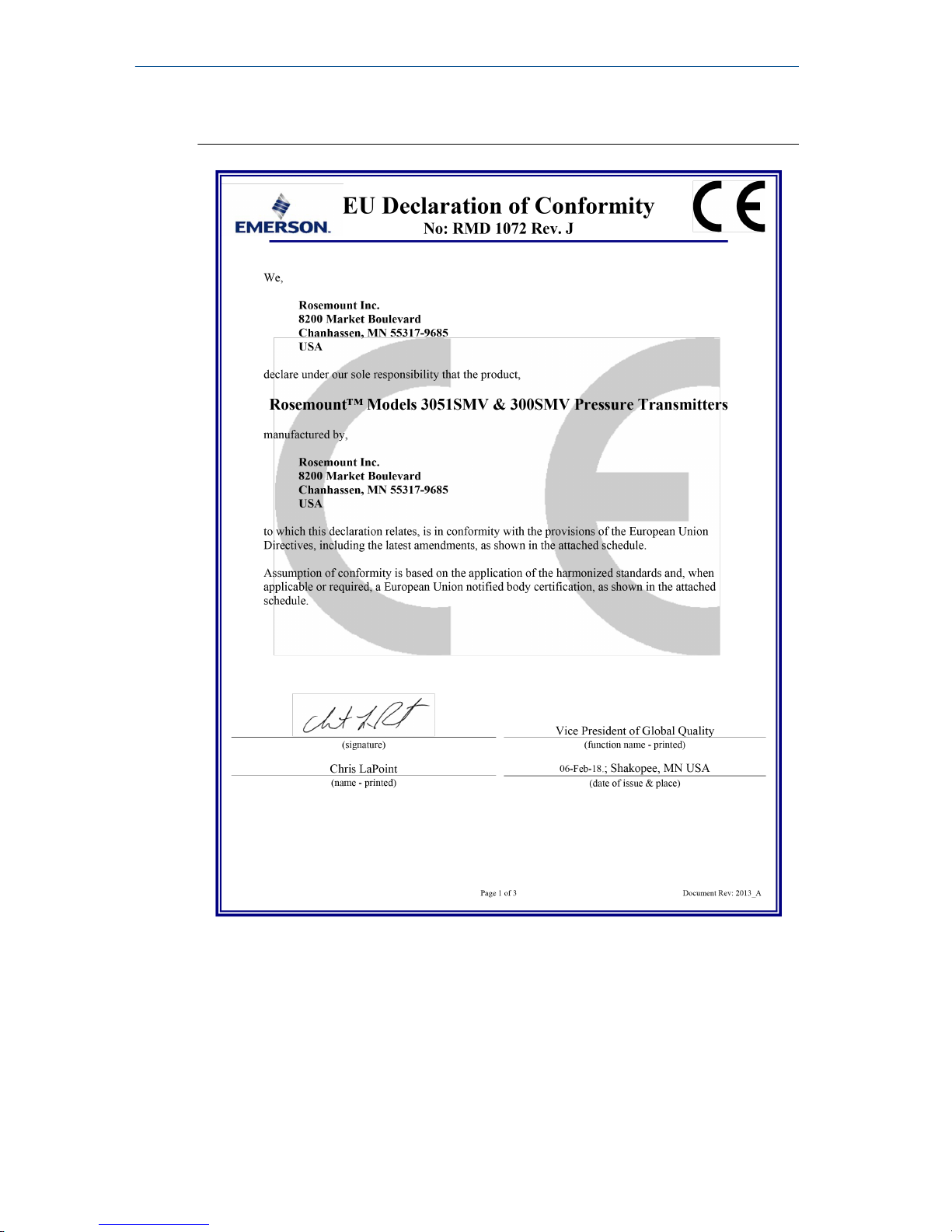
10.2 Declaration of Conformity
Quick Start Guide October 2018
48 Rosemount 3051SMV
Page 49
October 2018 Quick Start Guide
Quick Start Guide 49
Page 50
Quick Start Guide October 2018
50 Rosemount 3051SMV
Page 51
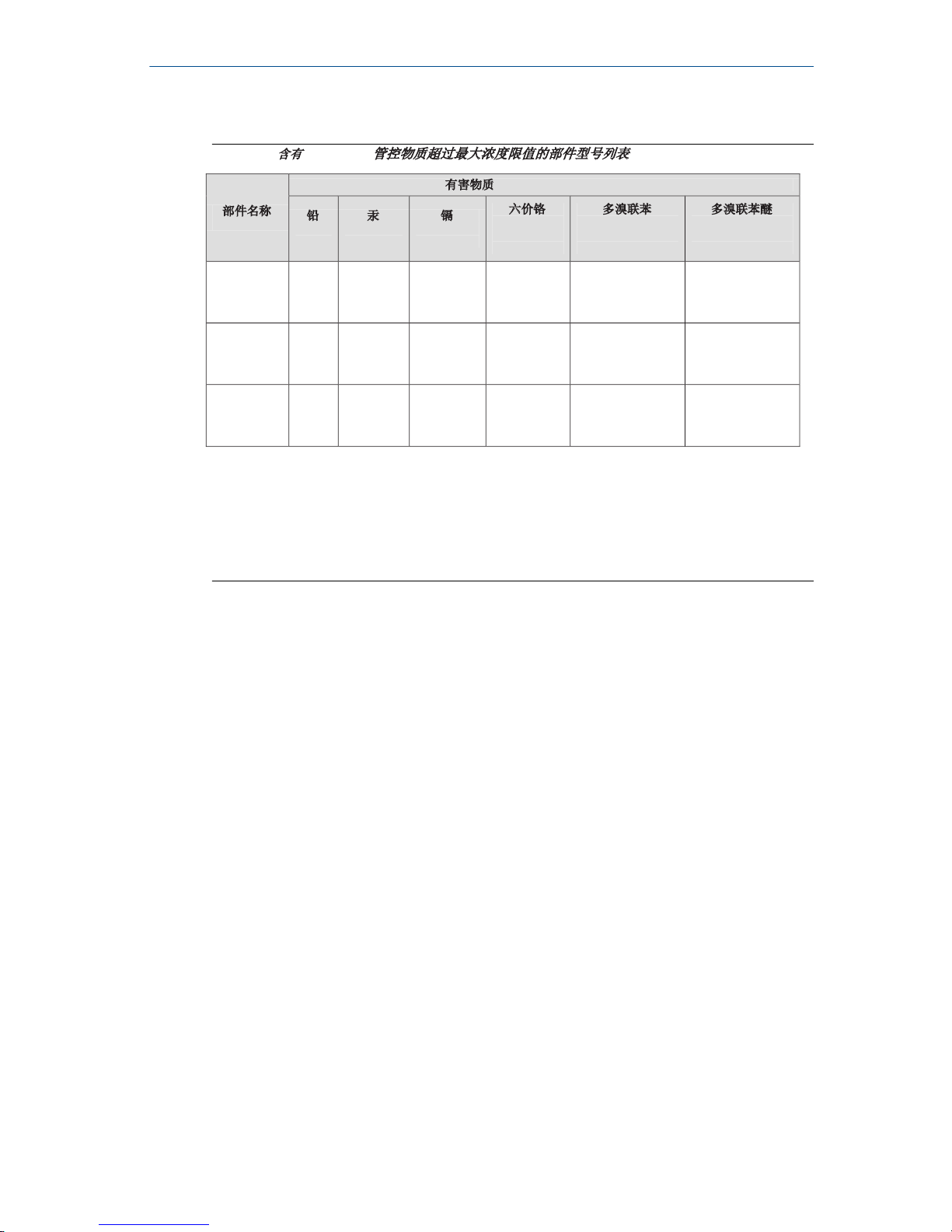
10.3 ChinaRoHS
ᴹ
China RoHS
㇑᧗⢙䍘䎵䗷ᴰབྷ⎃ᓖ䲀٬Ⲵ䜘Ԧරࡇ㺘
Rosemount 3051SMV
List of Rosemount 3051SMV Parts with China RoHS Concentration above MCVs
䜘Ԧ〠
Part Name
ᴹᇣ⢙䍘
/ Hazardous Substances
䫵
Lead
(Pb)
⊎
Mercury
(Hg)
䭹
Cadmium
(Cd)
ޝԧ䬜
Hexavalent
Chromium
(Cr +6)
ཊⓤ㚄㤟
Polybrominated
biphenyls
(PBB)
ཊⓤ㚄㤟䟊
Polybrominated
diphenyl ethers
(PBDE)
⭥ᆀ㓴Ԧ
Electronics
Assembly
X O O O O O
༣փ㓴Ԧ
Housing
Assembly
X O O X O O
Րᝏಘ㓴Ԧ
Sensor
Assembly
X O O X O O
ᵜ㺘Ṭ㌫ᦞ
SJ/T11364
Ⲵ㿴ᇊ㘼ࡦ
This table is proposed in accordance with the provision of SJ/T11364.
O:
Ѫ䈕䜘ԦⲴᡰᴹ൷䍘ᶀᯉѝ䈕ᴹᇣ⢙䍘Ⲵ䟿൷վҾ
GB/T 26572
ᡰ㿴ᇊⲴ䲀䟿㾱≲
O: Indicate that said hazardous substance in all of the homogeneous materials for this part is below the limit requirement of
GB/T 26572.
X:
Ѫ൘䈕䜘Ԧᡰ֯⭘Ⲵᡰᴹ൷䍘ᶀᯉ䟼ˈ㠣ቁᴹа㊫൷䍘ᶀᯉѝ䈕ᴹᇣ⢙䍘Ⲵ䟿儈Ҿ
GB/T 26572
ᡰ㿴ᇊⲴ䲀䟿㾱≲
X: Indicate that said hazardous substance contained in at least one of the homogeneous materials used for this part is above
the limit requirement of GB/T 26572.
October 2018 Quick Start Guide
Quick Start Guide 51
Page 52

*00825-0100-4803*
Quick Start Guide
00825-0100-4803, Rev. EG
October 2018
Global Headquarters
Emerson Automation Solutions
6021 Innovation Blvd.
Shakopee, MN 55379, USA
+1 800 999 9307 or +1 952 906 8888
+1 952 949 7001
[email protected]
North America Regional Office
Emerson Automation Solutions
8200 Market Blvd.
Chanhassen, MN 55317, USA
+1 800 999 9307 or +1 952 906 8888
+1 952 949 7001
[email protected]
Latin America Regional Office
Emerson Automation Solutions
1300 Concord Terrace, Suite 400
Sunrise, FL 33323, USA
+1 954 846 5030
+1 954 846 5121
[email protected]
Europe Regional Office
Emerson Automation Solutions Europe
GmbH
Neuhofstrasse 19a P.O. Box 1046
CH 6340 Baar
Switzerland
+41 (0) 41 768 6111
+41 (0) 41 768 6300
[email protected]
Asia Pacific Regional Office
Emerson Automation Solutions
1 Pandan Crescent
Singapore 128461
+65 6777 8211
+65 6777 0947
[email protected]
Middle East and Africa Regional Office
Emerson Automation Solutions
Emerson FZE P.O. Box 17033
Jebel Ali Free Zone - South 2
Dubai, United Arab Emirates
+971 4 8118100
+971 4 8865465
[email protected]
Linkedin.com/company/Emerson-
Automation-Solutions
Twitter.com/Rosemount_News
Facebook.com/Rosemount
Youtube.com/user/
RosemountMeasurement
Google.com/+RosemountMeasurement
©
2018 Emerson. All rights reserved.
Emerson Terms and Conditions of Sale are
available upon request. The Emerson logo is a
trademark and service mark of Emerson Electric
Co. Rosemount is mark of one of the Emerson
family of companies. All other marks are the
property of their respective owners.
 Loading...