

Page 1
40
Carbon Dioxide Sensor
Carbon Dioxide Sensor
Product Information Sheet
Product Information Sheet
210-2000
Overview
CPC’s CO2 sensor (P/N 210-2000) is a non-dispersive
infrared analyzer designed for measuring
environmental CO
systems and indoor spaces. Its measurement range of
0-2000 or 0-5000 ppm covers the range required to
monitor compliance with ASHRAE and other
ventilation efficiency standards.
An LCD display is available to provide local indication
of CO
calibration process. An adjustable setpoint relay is
available for direct control and alarm applications.
Microprocessor-based digital electronics and a
unique self-calibration algorithm improves long-term
stability and accuracy
concentration and facilitate the setup and
2
concentration in ventilation
2
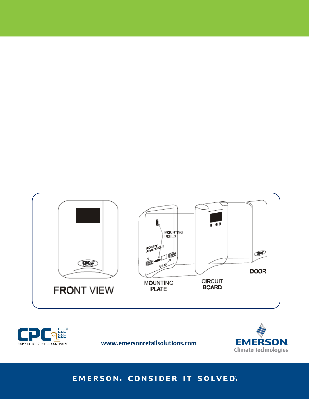
Mounting
Before mounting, remove the door from the circuit
board by pressing a screwdriver against the locking
tab on the top of the enclosure. Pry the circuit board
Figure 1 - CO2 Sensor (exploded view)
away from the mounting plate using a screwdriver
inserted into the two tab slots on the top of the
enclosure.
Choose a location for the sensor with good air
circulation, away from ventilation inlets, doors,
windows, or other points where fresh air enters the
room. The sensor should be mounted at least 4-1/2
feet above the floor. The environment temperature
must be within 32°–112°F (0°–50°C).
If wiring will be coming in through the mounting
plate from the back, punch out openings in the
mounting plate and use the plate as a template for
locating holes. Mount the mounting plate against a
wall or other flat surface by using the two mounting
holes and the screws provided (use wall anchors for
drywall installations).
NOTE: Sensors must be mounted vertically (straight
up and down) to ensure proper readings.
Page 2
41
Carbon Dioxide Sensor
Product Information Sheet
210-2000
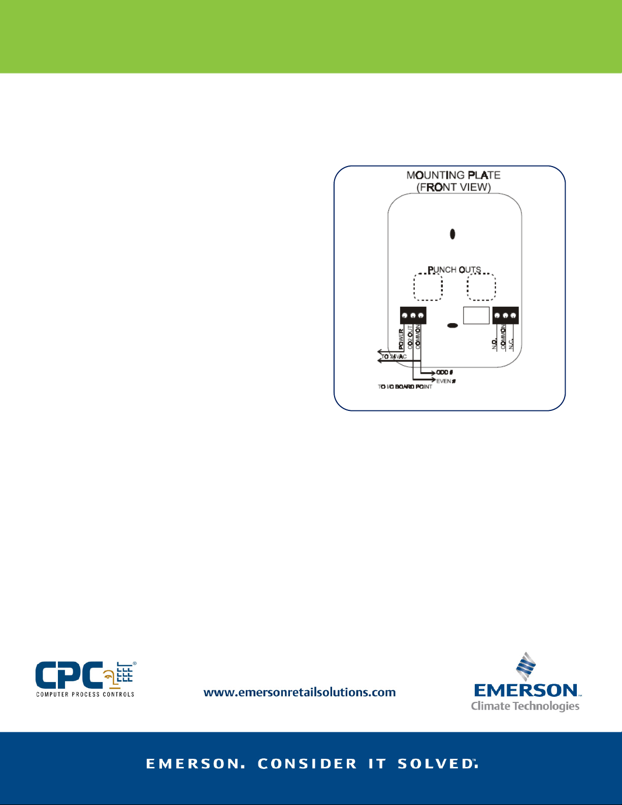
Wiring
The mounting plate has two sets of three-terminal
connectors. The connector on the left side of the
mounting plate is where sensor power and the signalto-I/O-board connection is made. The connector on
the right side is where connection to the on-board
relay is made.
Power Wiring
The CO2 sensor requires 24VAC power from a noncenter-tapped transformer. The sensor draws a
maximum of 3VA power. CPC recommends P/N 6400039, 10VA, 110VAC non-center-tapped Class 2
transformer.
Wire the transformer secondary to the connector on
the left side of the mounting plate, as shown in Figure
2.
Analog Output Wiring
The middle terminal of the connector on the left side
of the mounting plate is the analog output that
communicates the current CO
the site controller. This connector is typically
connected to a point on an I/O board, such as a 16AI,
16AIe, or 8DO. Wire the middle (SIGNAL) terminal on
the CO
I/O board point. Wire the COMMON terminal on the
CO
board point. See Figure 2.
sensor to the even numbered terminal of the
2
sensor to the odd numbered terminal of the I/O
2
Relay Wiring
The CO2 sensor has an on-board relay that changes
state to indicate a CO
programmed set point. This relay can be used as a
digital input on an input board point, or it can be used
to directly activate or deactivate an alarm
annunciator or a device that controls ventilation.
The connector on the right side of the mounting plate
is a Form C connector for the CO
Connect the input board point or device to the
concentration level to
2
level higher that a
2
sensor relay.
2
middle (COMMON) terminal of this connector, and
either the N.C. or N.O. terminal, depending on
whether you want the relay to be OPEN or CLOSED
when the CO
See Figure 2.
concentration is below the set point.
2
Figure 2 - CO2 Sensor Wiring
Reassembly After Wiring
When you are finished wiring power and I/O to the
connectors on the mounting plate, reconnect the
circuit board to the mounting plate. Push the top end
of the circuit board into the mounting plate so the
two hooked tabs on the circuit board are underneath
the tabs on the mounting plate. Then, gently press
down on the bottom part of the circuit board until it
snaps into place. See Figure 3.
If you have trouble pushing the circuit board in, check
to see if the pins on the back of the circuit board are
properly aligned with the power and relay connectors
on the mounting plate. Also verify that there are no
loose wires getting in the way.
Page 3

3
- CO2
y
4
-
s
42
Carbon Dioxide Sensor
Product Information Sheet
210-2000
Figure
Sensor Reassembl
Setting the Volts/Amps
Switch
The front of the circuit board has a switch that
controls whether the analog output sends a signal as
voltage (V) or milliamps (mA). To work with CPC I/ O
boards, this switch should be set to voltage (the
DOWN position). Verify this switch is in the DOWN
position before operating the sensor.
Setting Up the CO2
Sensor Software
Before operating the sensor, you must use the LCD
display and the three buttons on the front of the
circuit board to set the sensor’s operating
parameters. Figure 4 shows the keys on the circuit
board and the setup screens. Use the ENTER key to
cycle through the setup screens, and the + and - keys
to adjust parameter values.
Figure
CO2 Sensor Keys and Screen
Setpoint
If you are using the CO2 sensor’s relay for alarming or
control, use the + and - keys to adjust the value of the
set point. When the CO
set point, the relay will energize. Press ENTER to save
the setpoint value.
sensor’s reading is above this
2
Altitude
To properly measure CO2 concentrations, you must
specify the approximate altitude of the site. Use the +
and - keys to select the number of feet above sea
level closest to the site’s altitude. Press ENTER to save
the altitude value.
CO2 Calibration
WARNING! Calibrating the CO2 sensor requires a gas
calibration kit. DO NOT perform a calibration without
this kit, or else the sensor will give erroneous
readings.
All CO2 sensors are shipped pre-calibrated, and will
only require calibration once every five years to
ensure proper readings. Calibration requires a special
gas kit available from CPC. Follow the instructions
that come with this kit to calibrate the sensor.
Otherwise, press ENTER to bypass this screen and
continue setup.
Page 4

43
Carbon Dioxide Sensor
Product Information Sheet
210-2000
Span
The Span parameter determines whether you want to
measure concentrations between 0-2000 ppm or 05000 ppm. If set to 2000 ppm, the sensor’s analog
output signal will be scaled properly so that the
highest output voltage corresponds to 2000 ppm.
Likewise, if set to 5000 ppm, the highest output
voltage will signify 5000 ppm. Press ENTER to save
settings.
Output
The Output parameter determines whether you want
the analog output voltage to vary from 0- 5VDC or
from 0-10 VDC. This parameter must
5VDC if the analog output is connected to an I/O
board’s input point. Press ENTER to save settings.
be set to 0-
Replacing the Door
Once all programming and wiring is done, the sensor
is ready for operation. Snap the door on to the front
of the circuit board to complete installation. The
sensor comes equipped with two doors: one with a
window that allows the screen to be shown, and one
with no window that covers the screen. Choose
whichever door is appropriate for your site.
Setting Up The Sensor
Type in Einstein and
REFLECS Controllers
The analog output of the CO2 sensor is a linear 05VDC signal, with 0V representing a concentration of
0 ppm, and 5V representing the maximum
concentration level (either 2000 ppm or 5000 ppm,
depending on the value of the Span parameter you
chose when setting up the sensor).
In order for Einstein and the REFLECS line of
controllers (RMCC, BEC, or BCU) to read the signal
from the CO
Control (for REFLECS) or the Analog Input Setup
Screen (for Einstein) as a Linear sensor. Refer to your
controller’s user manual for more information on the
Linear sensor type and how to program its
parameters.
When setting up the sensor in Einstein or REFLECS,
you will need to include the following information:
Gain: The Gain is the number that will be multiplied
with the number of volts coming from the CO
sensor’s analog output to yield the concentration
value. If the sensor’s Span is set to 5000 ppm, use a
Gain value of 1000. If the Span is set to 2000 ppm,
use a Gain value of 400.
Offset: Because all calibration is handled by the
sensor itself, the CO
zero.
sensor, it must be set up under Sensor
2
sensor’s offset should be set to
2
2
EmersonTM, Emerson. Consider It SolvedTM and Emerson Climate TechnologiesTM logos are trademarks and service marks of Emerson Electric Co.
Intelligent Store
TM
is a trademark of Emerson Climate Technologies. All other trademarks are the property of their respective owners.
© 2011 Emerson Climate Technologies, Inc. All rights reserved.
 Loading...