

Page 1
Model 2081C/T
Conductivity Microprocessor Transmitter
Instruction Manual
PN 51-2081C/T/rev.B
April 2003
Page 2

ESSENTIAL INSTRUCTIONS
READ THIS PAGE BEFORE PROCEEDING!
Rosemount Analytical designs, manufactures, and tests its
products to meet many national and international standards.
Because these instruments are sophisticated technical products, you must properly install, use, and maintain them to
ensure they continue to operate within their normal specifications. The following instructions must be adhered to and integrated into your safety program when installing, using, and
maintaining Rosemount Analytical products. Failure to follow
the proper instructions may cause any one of the following situations to occur: Loss of life; personal injury; property damage;
damage to this instrument; and warranty invalidation.
• Read all instructions prior to installing, operating, and servicing the product. If this Instruction Manual is not the correct
manual, telephone 1-800-654-7768 and the requested manual will be provided. Save this Instruction Manual for future
reference.
• If you do not understand any of the instructions, contact your
Rosemount representative for clarification.
• Follow all warnings, cautions, and instructions marked on and
supplied with the product.
• Inform and educate your personnel in the proper installation,
operation, and maintenance of the product.
• Install your equipment as specified in the Installation
Instructions of the appropriate Instruction Manual and per
applicable local and national codes. Connect all products to
the proper electrical sources.
• To ensure proper performance, use qualified personnel to
install, operate, update, program, and maintain the product.
• When replacement parts are required, ensure that qualified
people use replacement parts specified by Rosemount.
Unauthorized parts and procedures can affect the product’s
performance and place the safe operation of your process at
risk. Look alike substitutions may result in fire, electrical hazards, or improper operation.
• Ensure that all equipment doors are closed and protective
covers are in place, except when maintenance is being performed by qualified persons, to prevent electrical shock and
personal injury.
NOTE
The Model 2081C/T Two-wire transmitter is certified for use in areas requiring intrinsic safety area by FM, CSA, and CENELEC. However, the CENELEC certification requires that a Model 2081C/T used with contacting sensors be certified separately from those using inductive (toroidal) sensors. The type of sensor must be specified with the order for a CENELEC
certified transmitter.
Since this decision is required prior to shipment, the instruction manual covers both configurations. However, if the transmitter is reconfigured in the field, it may not meet CENELEC certification conditions.
Emerson Process Management
Rosemount Analytical Inc.
2400 Barranca Parkway
Irvine, CA 92606 USA
Tel: (949) 757-8500
Fax: (949) 474-7250
http://www.raihome.com
© Rosemount Analytical Inc. 2003
About This Document
This manual contains instructions for installation and operation of the Model 2081C/T Conductivity
Transmitter. The following list provides notes concerning all revisions of this document.
Rev. Level Date Notes
A 7/01 This is the initial release of the product manual. The manual has been refor-
matted to reflect the Emerson documentation style and updated to reflect any
changes in the product offering.
B 4/03 Updated CE certification
Page 3

MODEL 2081C/T CONDUCTIVITY
MICROPROCESSOR TRANSMITTER
TABLE OF CONTENTS
Section Title Page
1.0 INSTALLATION ...................................................................................................... 1
1.1 Unpacking and Inspection....................................................................................... 1
1.2 Mechanical Installation............................................................................................ 1
1.3 Wiring ...................................................................................................................... 1
1.4 Fault Mode and Security Jumpers .......................................................................... 2
1.5 Calibration and Setup.............................................................................................. 3
1.6 Hazardous Locations — Explosion Proof Installation ............................................. 3
1.7 Hazardous Locations — Intrinsically Safe Installation ............................................ 3
2.0 DESCRIPTION OF CONTROLS ............................................................................ 17
2.1 General.................................................................................................................... 17
2.2 Menu Selection ....................................................................................................... 17
2.3 Value Adjustment .................................................................................................... 17
3.0 RANGE CONFIGURATION .................................................................................... 18
3.1 General.................................................................................................................... 18
4.0 START UP AND CALIBRATION ............................................................................ 19
4.1 General.................................................................................................................... 19
4.2 Temperature Calibration.......................................................................................... 19
4.3 Entering the Cell Constant ...................................................................................... 19
4.4 Zeroing the System ................................................................................................. 19
4.5 Initial Loop Calibration............................................................................................. 19
4.6 Routine Standardization.......................................................................................... 21
4.7 Hold Mold for Maintenance ..................................................................................... 21
4.8 Sensor Maintenance ............................................................................................... 21
5.0 KEYBOARD SECURITY ........................................................................................ 22
5.1 Push Button Security............................................................................................... 22
5.2 Eeprom Security...................................................................................................... 22
6.0 DIAGNOSTICS AND TROUBLESHOOTING......................................................... 23
6.1 General.................................................................................................................... 23
6.2 Contact Conductivity Mode Bench Check............................................................... 24
6.3 Toroidal Conductivity Mode Bench Check .............................................................. 25
6.4 Systematic Troubleshooting.................................................................................... 25
7.0 THEORY OF OPERATION ..................................................................................... 29
7.1 General.................................................................................................................... 29
7.2 Overview ................................................................................................................. 29
8.0 DESCRIPTION AND SPECIFICATIONS................................................................ 31
8.1 Features .................................................................................................................. 31
8.2 Functional Specifications ........................................................................................ 32
8.3 Performance Specifications .................................................................................... 32
8.4 Physical Specifications............................................................................................ 33
8.5 Recommended Sensors.......................................................................................... 33
8.6 Ordering Information ............................................................................................... 34
8.7 Accessories ............................................................................................................. 34
9.0 RETURN OF MATERIAL........................................................................................ 36
i
MODEL 2081C/T TABLE OF CONTENTS
Page 4

ii
TABLE OF CONTENTS CONT’D.
LIST OF FIGURES
Figure No. Title Page
1-1 Model 2081C/T Dimensional/Mounting Instructions
with Power Supply/Loop Signal Wiring ................................................................... 4
1-2 Model 2081C/T Contacting Electrode Wiring.......................................................... 5
1-3 Model 2081C/T Inductive Sensor Wiring ................................................................ 6
1-4 Fault and Security Jumper Locations...................................................................... 7
1-5 Sensor To Transmitter Switch Settings ................................................................... 7
1-6 Explosion Proof System Installation Schematic ..................................................... 8
1-7 Intrinsically Safe (BASEEFA) Wiring for Model 2081C ........................................... 9
1-8 Intrinsically Safe (BASEEFA) Wiring for Model 2081T .......................................... 11
1-9 Intrinsically Safe (CSA) Wiring for Model 2081C/T ................................................ 13
1-10 Intrinsically Safe (FM) Wiring for Model 2081C/T .................................................. 15
3-1 Menu Description .................................................................................................... 17
5-1 Jumper Locations.................................................................................................... 22
6-1 Bench Check (Contact Sensor) .............................................................................. 26
6-2 Bench Check (Toroidal Sensor) .............................................................................. 26
6-3 Troubleshooting Flow Chart .................................................................................... 28
7-1 Block Diagram......................................................................................................... 29
8-1 Load/Power Supply Requirements.......................................................................... 32
8-2 Model 275 HART
®
Communication Menu Tree-Model 2081C/T............................ 35
LIST OF TABLES
Table No. Title Page
3-1 Sensors used with Model 2081C/T conductivity..................................................... 18
3-2 Measurement Ranges............................................................................................. 18
6-1 Diagnostic Messages.............................................................................................. 23
6-2 Resistance Values (Temperature) ........................................................................... 24
6-3 Resistance Values (Conductivity)............................................................................ 24
6-4 Quick Troubleshooting Guide.................................................................................. 27
8-1 Local Interference Functions................................................................................... 32
8-2 Measurement Ranges............................................................................................. 32
MODEL 2081C/T TABLE OF CONTENTS
Page 5

SECTION 1.0 INSTALLATION
1.1 UNPACKING AND INSPECTION. Inspect the
transmitter for shipping damage. If damaged, notify the
carrier immediately.
Confirm that all items shown on the packing list are
present. Notify Rosemount Analytical if any items are
missing.
If the transmitter appears to be in satisfactory condition
proceed to Section 1.2.
NOTE
Save the original packing cartons and materials as most carriers require proof of damage
due to mishandling.
1.2 MECHANICAL INSTALLATION.
1.2.1 General. The transmitter may be installed in
harsh environments. However, it should be installed in
an area where sources of extreme temperature fluctuation, vibration and shock are at a minimum or absent.
Installation site should:
1. permit the use of the standard cable lengths
(unless a junction box is used),
2. be easily accessed by operating and maintenance
personnel, and
3. be at least 12 inches (.3 m) from sources of high
voltage.
NOTE
Before installing the transmitter, it should
be determined whether the Model 275 will
be used with the 2081C/T.
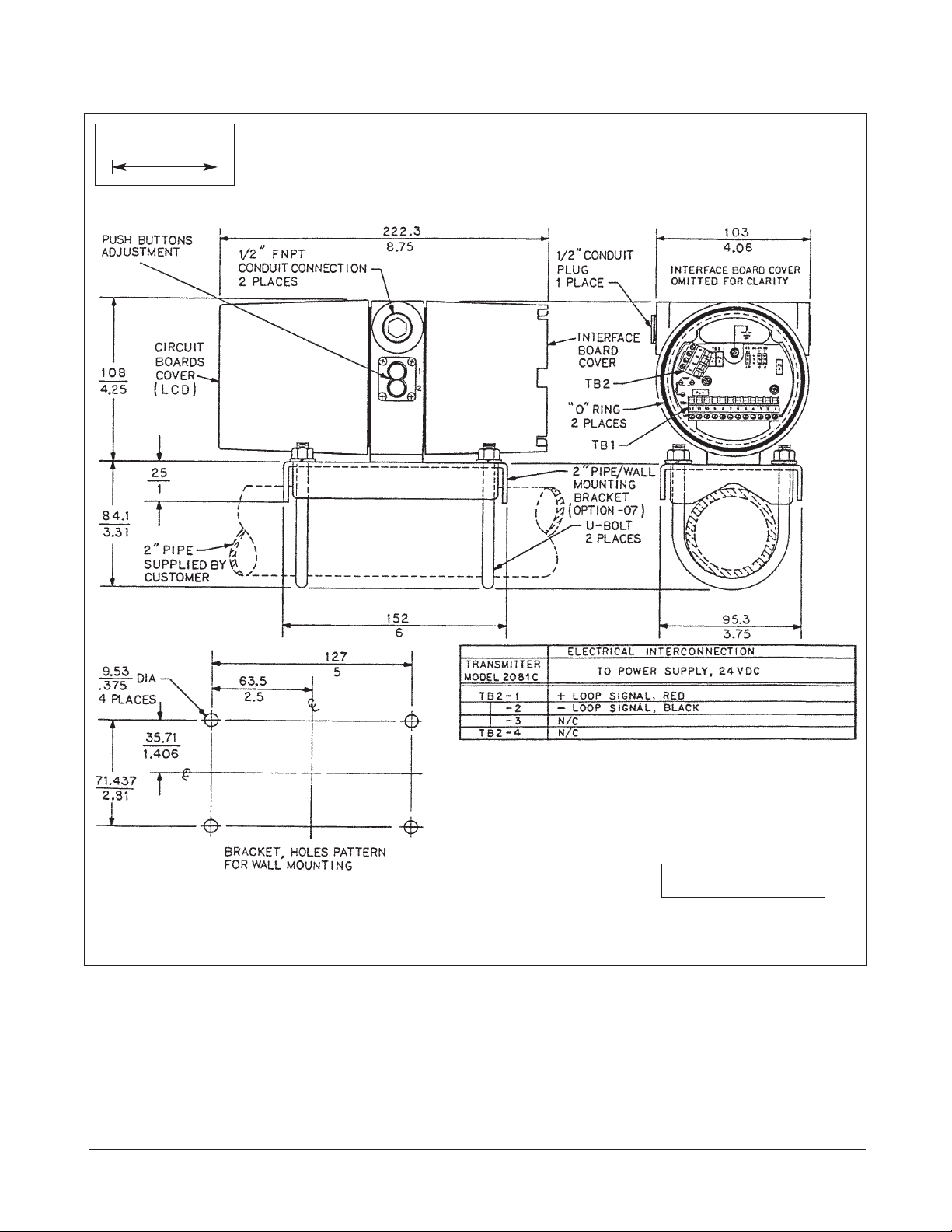
1.2.2 Mounting. The transmitter may be mounted on a
flat surface using the two threaded mounting holes
located on the bottom of the transmitter or through the
use of an optional 2-inch pipe/wall mounting bracket,
Code 07 (Figure 1-1).
NOTE
The meter may be installed in 90-degree
increments for easy viewing. Remove the
four screws holding the meter in place and
change the meter to the desired angle. Plug
in the display and tighten the four screws.
1.3 WIRING. The transmitter is equipped with two 1/2-
inch NPT conduit openings, one on each side of the
housing. One is for the power supply/signal wiring and
the other is for the sensor wiring.
The use of weathertight cable glands or conduit is
recommended to prevent moisture from entering the
housing. Conduit should be positioned to prevent condensation from draining into the housing. Conduit connections on the transmitter housing should be plugged
and sealed to avoid moisture accumulation inside the
terminal section of the housing.
CAUTION
If the connections are not sealed, mount transmitter with the electrical housing positioned
downward for drainage. Wiring should be
installed with a drip loop. The bottom of the
drip loop should be lower than the conduit connections or the transmitter housing.
1.3.1 Power Supply/Signal Wiring. It is recommended that the signal wiring be shielded, twisted pairs that
are grounded. The best place to ground the loop is at
the negative terminal of the power supply. Do not
ground the signal loop at more than one point. The
transmitter case shall be grounded. The power and
signal wiring terminal is TB2 terminals 1 through 4 as
shown in either Figures 1-1, 1-2, and 1-3.
Signal or sensor wiring should never be run in the
same conduit or open tray as AC power or relay actuated signal cables. Keep signal or sensor wiring at
least 12 in. (.3 m) from heavy electrical equipment.
NOTE
For best EMI/RFI protection the power supply/signal cable should be shielded and
enclosed in an earth grounded, rigid metal
conduit. Connect the cable’s outer shield to
the ground terminal near TB2, Figure 1-1. The
sensor cable should also shielded. The cable’s
outer shield shall be connected to the earth
ground terminal provided near TB2, Figure 1-
1. If the outer shield is braided an appropriate
metal cable gland fitting maybe used to connect the braid to earth ground via the instrument case.
A new addition to the suite of tests done to
ensure CE compliance is IEC 1000-4-5. This is
a surge immunity test that simulates overvoltages due to switching and lightning transients.
In order to meet the requirements of this test,
additional protection must be added to the
instrument in the form of a Transient Protector
such as the Rosemount Model 470D. This is a
3½-inch tube with ½-inch MNPT threads on
both ends. Inside the tube are gas discharge
and zener diode devices to limit surges to the
transmitter from the current loop. No additional protection is needed on the sensor connections.
1
MODEL 2081C/T SECTION 1.0
INSTALLATION
Page 6

2
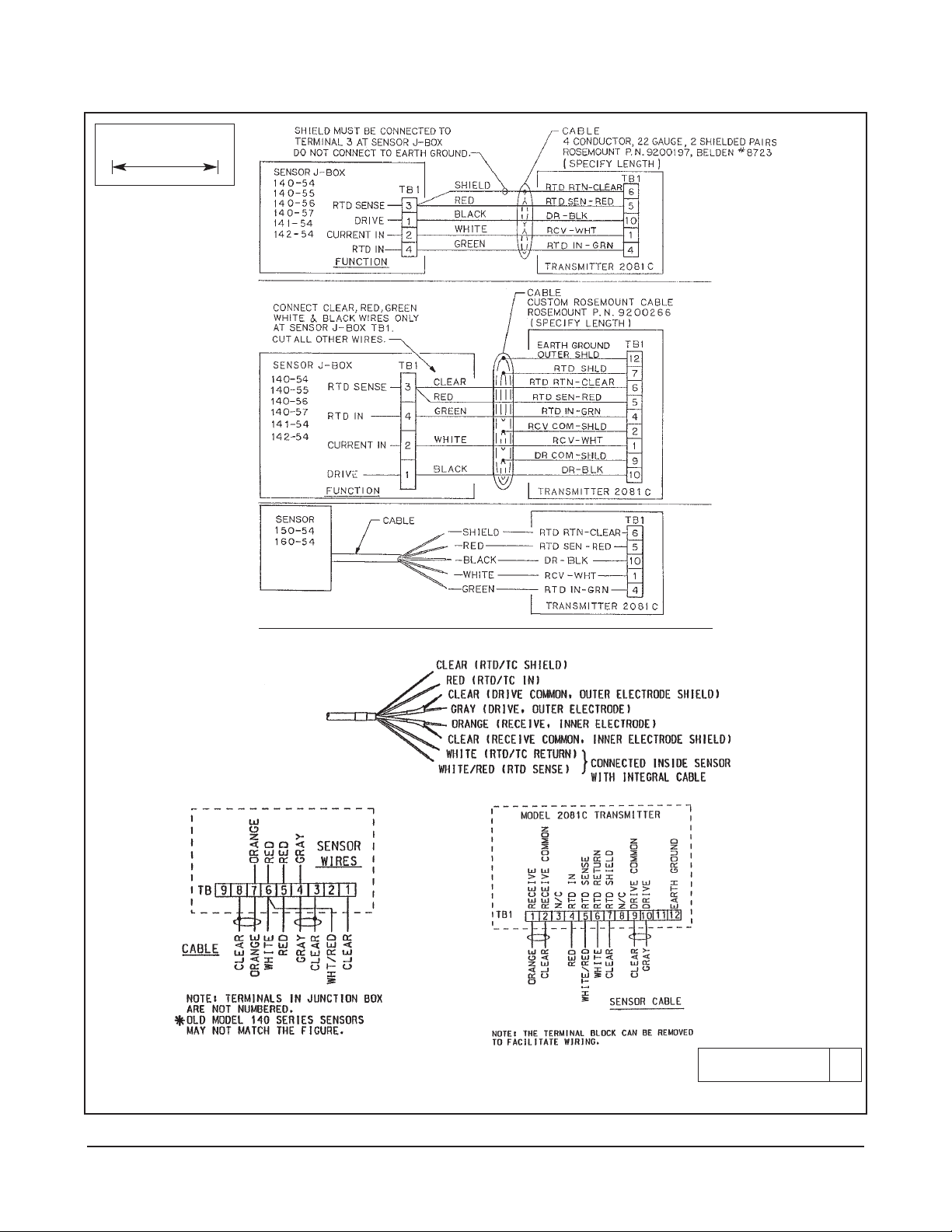
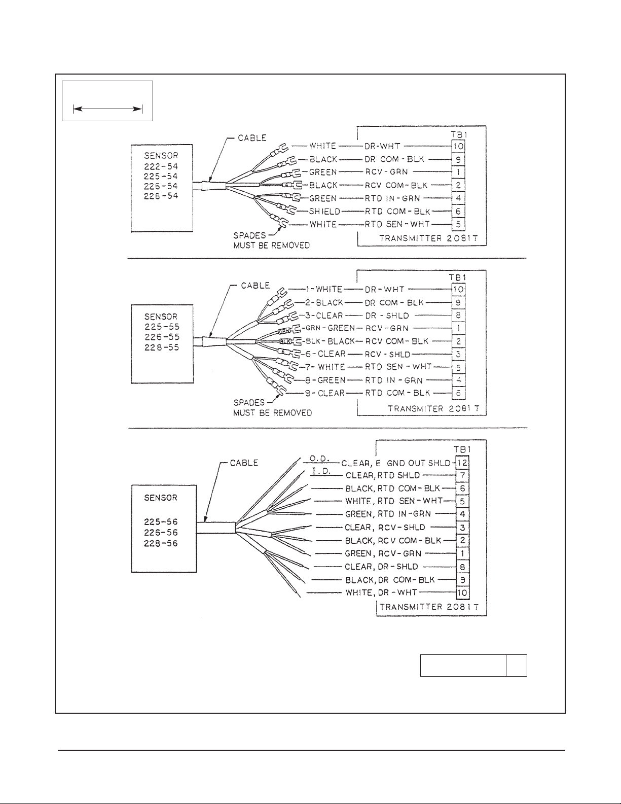
1.3.2 Sensor Wiring. The sensor wiring terminals are
located on the side opposite to the LCD meter. Remove
the housing cover to gain access. Pass the sensor cable
through the transmitter’s conduit opening. Connect the
sensor wiring to TB1 terminals 1 through 12 as shown on
Figures 1-2 and 1-3.
NOTE
If the standard cable length is not sufficient
for the planned installation, the use of a
junction box with extension cable is strongly recommended. Do not exceed 250 feet
(76m) total cable length from the sensor to
the transmitter.
1.3.3 Matching Transmitter to sensor. Switches S4 and
S5 are used to normalize the transmitter for Toroidal or
contact sensors. See Figure 1-5.
Switches S4 and S5 should both be set to T when Toroidal
sensors are installed, C when Contact sensors are
installed.
Switches S1 and S2 are used to select the sensitivity
range of the LCD. To obtain desired switch settings, multiply the cell constant of the probe being used by the maximum low range value. If the working range of the process
is below this calculated value then set both switch to Lo.
If the working range of the process is above this calculated value then set both switch to Hi (see table below).
Sample: Model 142 sensor: .2 (cell constant) x
4,000µS (maximum low range value)= 800µS (calculated value).
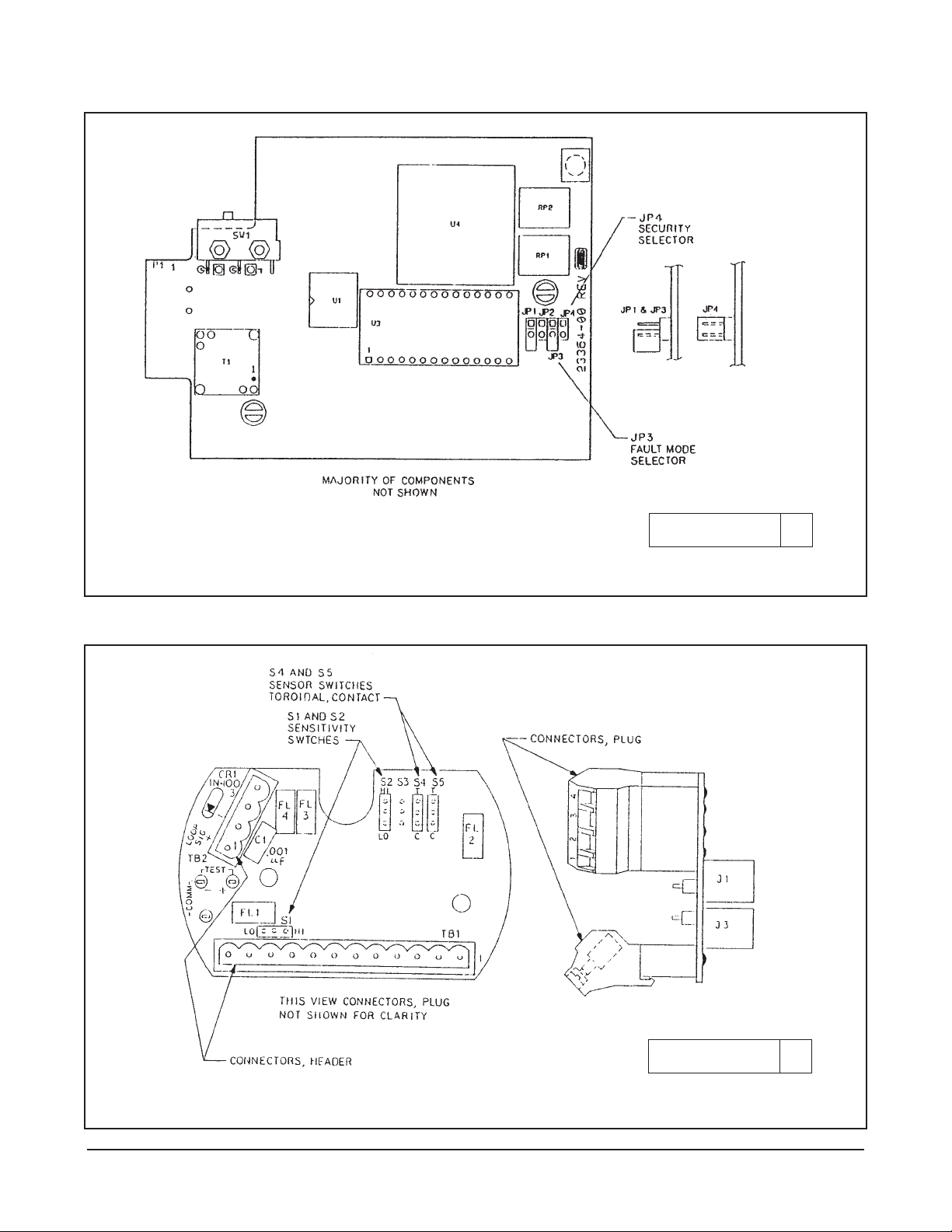
1.4 FAULT MODE AND SECURITY
JUMPER
1.4.1 General This section describes how to set the
jumpers on the CPU board for the following (See
Figure 1-4).
1. Output value in fault (alarm) mode
2. Security - Write Disable
3. Security - Push Buttons
CAUTION
The circuit board is electrostatically sensitive.
Be sure to observe handling precautions for
static-sensitive components.
1.4.2 Fault Mode Output. The default output of the
transmitter during a fault condition is determined by the
position of the default current output jumper JP3 (refer to
Figure 1-4). The output can be set to default either:
– below 4mA - JP3 with jumper.
– above 20mA - JP3 without jumper (factory setting).
Store jumper on one post to prevent misplacing it. See
Section 8.0 for corrective actions for fault messages.
1.4.3 Security. Also explained in Section 6.0. These
jumpers are located on the CPU board. See Figure 1-4
for location.
– Disable 2081 push buttons - JP4 without jumper.
(Store jumper on one post to prevent misplacing it).
– Enable 2081 push buttons - JP4 with jumper (fac-
tory setting).
– Disable all changes to configuration - JP1. Jumper
in place disables any (EEPROM or push button)
changes.
– Allow changes to configuration - JP1 Jumper on
one post only will enable configuration changes.
Mnemonic Fault
SLP – FAIL - 2 point calibration error
AdC – FAIL - Transmitter electronics failure
(A/D converter)
rngE – LOOP - Conductivity value outside 4-20 mA
range points
tEnP – Lo - Temperature too low or RTD shorted
tEnP – Hi - Temperature too high or RTD open
Type Maximum Switch
Sensor Range Setting
Toroidal Below 400,000µS x Cell Constant Both “Lo”
Above 400,000µS x Cell Constant Both “Hi”
Contacting Below 4,000µS x Cell Constant Both “Lo”
Above 4,000µS x Cell Constant Both “Hi”
MODEL 2081C/T SECTION 1.0
INSTALLATION
Page 7

3
1.5 CALIBRATION AND SET-UP
Instructions for output current ranging, security set ups,
and calibration of sensor temperature, cell constant
etc, are contained in Sections 2.0 through 5.0.
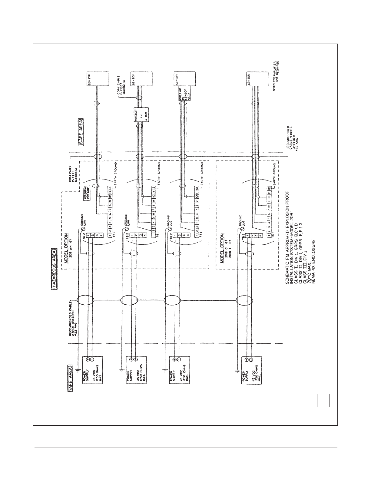
1.6 HAZARDOUS LOCATIONS —
EXPLOSION PROOF INSTALLATIONS
In order to maintain the explosion proof rating for
installed transmitter, the following conditions must be
met.
1. Code 67 must be specified when ordering F.M.
(Factory Mutual) units.
2. Explosion proof installation must be in accordance
with Drawing Number 1400160 (see Figure 1-6).
3. The transmitter enclosure covers must be on hand
tight and the threads must not be damaged.
NOTE
These covers seat on rings which serve to
provide a dust proof enclosure for Class II
and Class III installations.
4. Explosion proof “Y” fittings must be properly
installed and plugged with a sealing compound to
prevent explosive gases from entering the transmitter. CSA has determined that the transmitter
housing is “Factory Sealed”. Installation of “Y” fittings and the use of sealing compound is not
required for CSA approved Explosion Proof installations.
NOTE
Do not install sealing compound until all
field wiring is completed.
CAUTION
Sealing compound must be installed prior
to applying power to the transmitter.
5. If one of the conduit connections on the housing is
not used, it must be closed with a threaded metal
plug with at least five threads engaged.
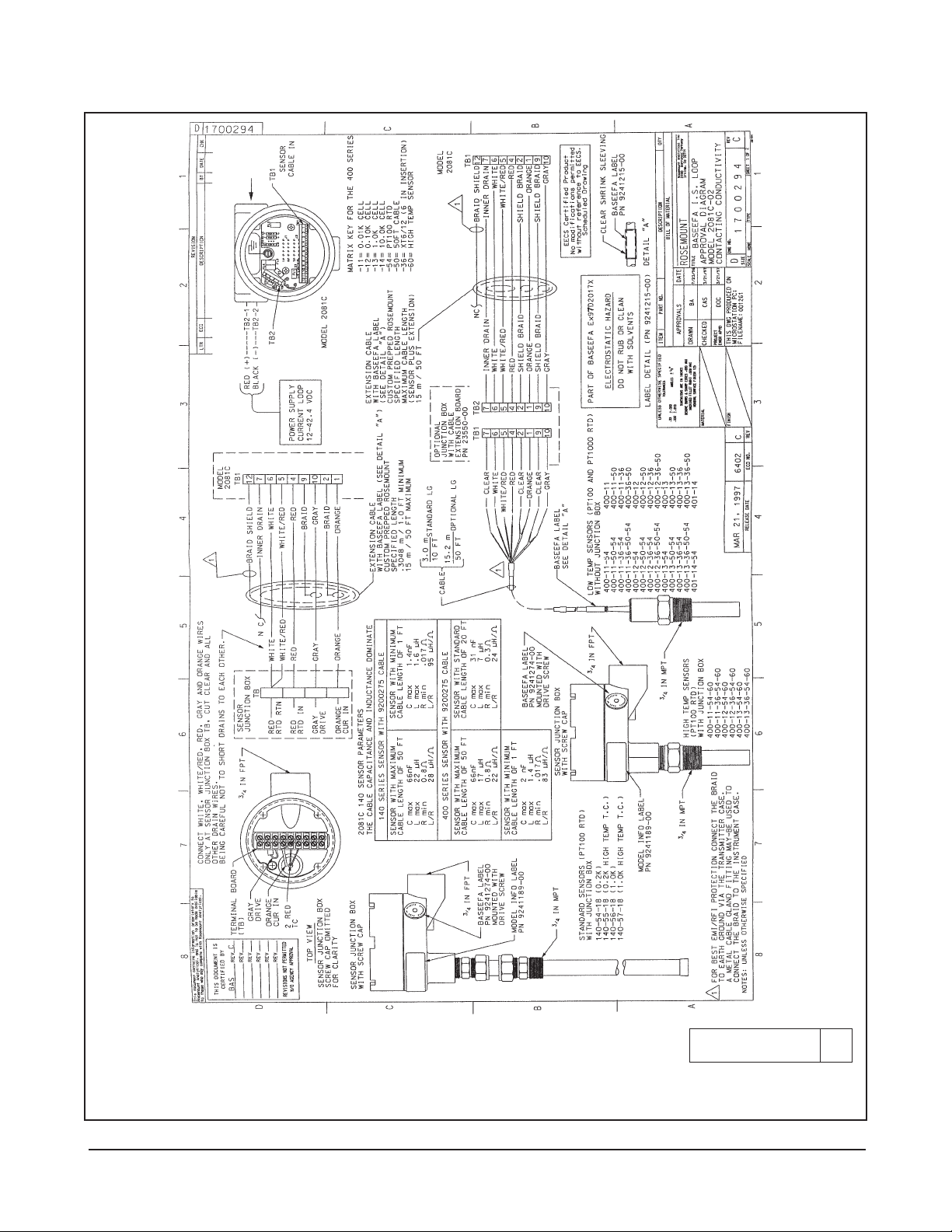
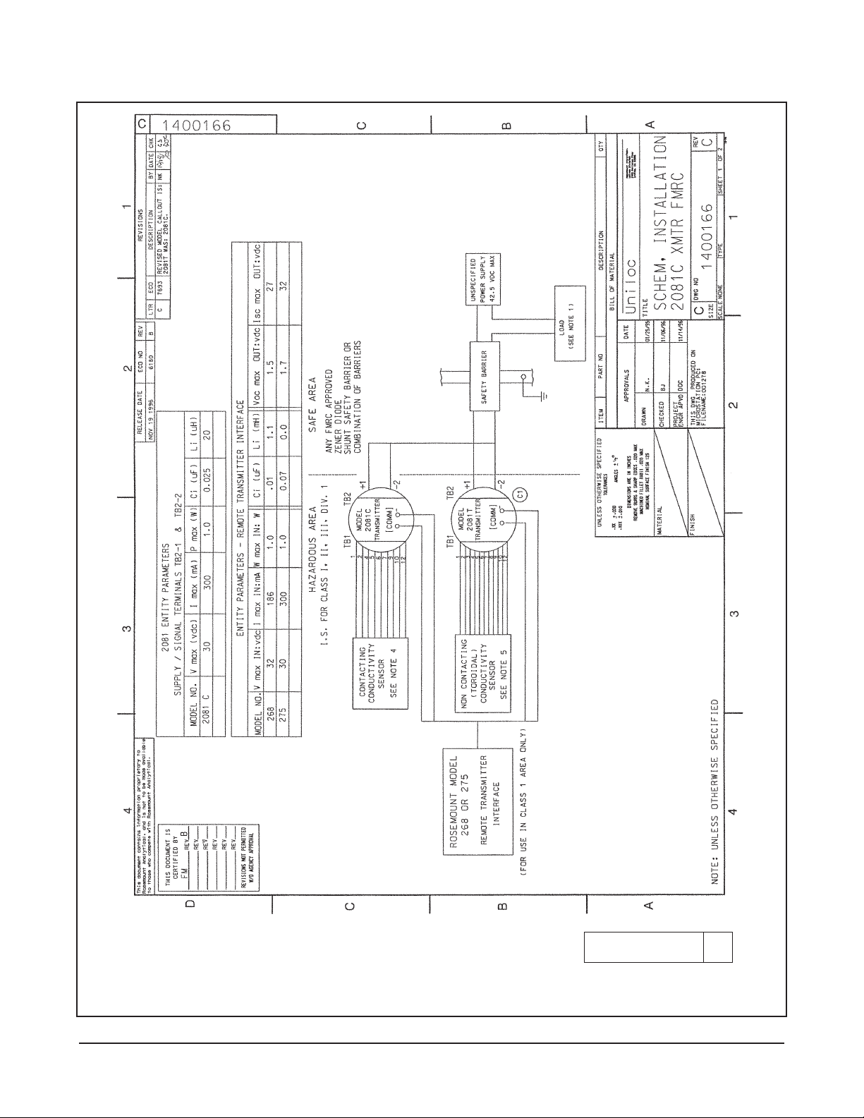
1.7 HAZARDOUS LOCATIONS —
INTRINSICALLY SAFE INSTALLATIONS
See Figure 1-7 for Model 2081C intrinsically safe installation (BASEEFA). See Figure 1-8 for Model 2081T
intrinsically safe installation (BASEEFA). See Figure 19 for Model 2081C and 2081T intrinsically safe installation (CSA). See Figure 1-10 for Model 2081C and
2081T intrinsically safe installation (FM).
MODEL 2081C/T SECTION 1.0
INSTALLATION
Page 8
4
FIGURE 1-1. Model 2081C/T Dimensional/Mounting Instructions with Power Supply/Loop Signal Wiring
WHEN INCH AND METRIC DIMS
ARE GIVEN
MILLIMETER
INCH
DWG. NO. REV.
40208120 A
MODEL 2081C/T SECTION 1.0
INSTALLATION
Page 9
5
WHEN INCH AND METRIC DIMS
ARE GIVEN
MILLIMETER
INCH
FIGURE 1-2. Model 2081C Contacting Electrode Wiring
PN 9200275
CABLE PN 9200275 - UNPREPPED
CABLE PN 23747-00 - PREPPED
CE approved cable for Sensor Models 140, 141, 142, 150, 400, 401, 402, 403, & 404 using cable PN 9200275 or 23747-00
WIRE FUNCTIONS
DWG. NO. REV.
40208119 A
MODEL 2081C/T SECTION 1.0
INSTALLATION
Page 10
6
FIGURE 1-3. Model 2081T Inductive Sensor Wiring
DWG. NO. REV.
40208106 C
WHEN INCH AND METRIC DIMS
ARE GIVEN
MILLIMETER
INCH
MODEL 2081C/T SECTION 1.0
INSTALLATION
Page 11
7
FIGURE 1-5. Sensor to Transmitter Switch Settings
FIGURE 1-4. Fault and Security Jumper Locations
DWG. NO. REV.
40208110 B
DWG. NO. REV.
40208109 A
MODEL 2081C/T SECTION 1.0
INSTALLATION
Page 12
8
FIGURE 1-6. Explosion Proof System Installation Schematic (FM)
DWG. NO. REV.
1400160 A
MODEL 2081C/T SECTION 1.0
INSTALLATION
Page 13
9
MODEL 2081C/T SECTION 1.0
INSTALLATION
FIGURE 1-7. Intrinsically Safe (BASEEFA) Wiring for Model 2081C
Part 1 of 2
DWG. NO. REV.
1700294 C
Page 14

MODEL 2081C/T SECTION 1.0
INSTALLATION
FIGURE 1-7. Intrinsically Safe (BASEEFA) Wiring for Model 2081C
Part 2 of 2
DWG. NO. REV.
1700294 C
10
Page 15

MODEL 2081C/T SECTION 1.0
INSTALLATION
FIGURE 1-8. Intrinsically Safe (BASEEFA) Wiring for Model 2081T
Part 1 of 2
DWG. NO. REV.
1700291 D
11
Page 16

MODEL 2081C/T SECTION 1.0
INSTALLATION
FIGURE 1-8. Intrinsically Safe (BASEEFA) Wiring for Model 2081T
Part 2 of 2
DWG. NO. REV.
1700291 D
12
Page 17

MODEL 2081C/T SECTION 1.0
INSTALLATION
FIGURE 1-9. Intrinsically Safe (CSA) Wiring for Model 2081C/T
Part 1 of 2
DWG. NO. REV.
1400169 B
13
Page 18

MODEL 2081C/T SECTION 1.0
INSTALLATION
FIGURE 1-9. Intrinsically Safe (CSA) Wiring for Model 2081C/T
Part 2 of 2
DWG. NO. REV.
1400169 B
14
Page 19
MODEL 2081C/T SECTION 1.0
INSTALLATION
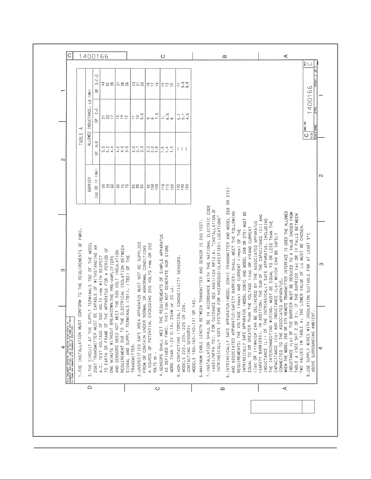
FIGURE 1-10. Intrinsically Safe (FM) Wiring for Model 2081C/T
Part 1 of 2
DWG. NO. REV.
1400166 C
15
Page 20
MODEL 2081C/T SECTION 1.0
INSTALLATION
FIGURE 1-10. Intrinsically Safe (FM) Wiring for Model 2081C/T
Part 2 of 2
DWG. NO. REV.
1400166 C
16
Page 21

17
SECTION 2.0 DESCRIPTION OF CONTROLS
Figure 3-1. Menu Description
2.2.2 Display Flags and Hold Mode. The transmitter
displays a flag on the LCD corresponding to the appropriate units.
When the transmitter is in hold output mode a flashing
flag will appear on the middle right hand side of the display and HoLd will flash periodically. The output will
remain at the last process value. To return the transmitter to normal operation, scroll to hold again and
release both buttons.
2.3 VALUE ADJUSTMENT. Selection of a menu item
that has a user-adjustable value will cause a numeric
display with the right-most digit flashing.
• Depressing and holding push button #1 will cause
the number flashing to increment upwards, looping
back to zero.
• Depressing push button #2 will shift the flashing
cursor to the next decade.
• Decimal position is shifted by pressing button #2 when
the left most digit is flashing under the Std menu.
Decimal will start flashing. Change location by
pressing button #1.
• Select millisiemens/microsiemens flag by going
through decimal position sequence and then
pressing button #2. Flag will start flashing. Press
button #1 to position the flag on the proper
choice. Press button #2 once more and sensor
will return to the starting point to change values.
Press both buttons in momentarily to enter displayed value into memory.
NOTE
The autoranging feature on the 2081C/T will
make decimal point setting and engr. unit settings
unnecessary.
MAIN MENU
dISP – – – – – – – – – –
Ê
Std
Standardize Conductivity
hold Initiate and remove hold output mode
-0- Zero sensor loop
LoC 4 mA range point
HiC 20 mA range point
CELL Cell constant
tAdJ Standardize temperature, °C
Atc Automatic temperature compensation
SLP Electrode slope (mV/pH)
tP1 Calibration point one
tP2 Calibration point two
DISPLAY SUBMENU
Cond Conductivity value
fct Cell factor
curr Output in mA
DIo
Output in % of full scale
DC Temperature, °C
DF Temperature, °F
Cin Absolute conductivity
2.1 GENERAL. Nearly all functions of the transmitter
are accessed through the dual push buttons. The
transmitter uses no potentiometer.
2.2 MENU SELECTION. The dual push buttons are
located on the side of the transmitter. Press and hold
both buttons to display the transmitter menu items.
See Figure 3-1. The display will show each item for
about one second then scroll to the next item. It will
continue to loop through the items until one is selected. To select an item, release both push buttons when
the desired item is displayed.
NOTE
When no push button is pressed for a period of 60 seconds, the transmitter defaults to
reading conductivity. If the push buttons are
accidentally released and this would upset
the process (e.g. tP2), escape by waiting 60
seconds for the transmitter to default to the
conductivity reading.
2.2.1 Display Submenu. The display submenu (dISP) is
used to access secondary process values that cannot
be changed.
To enter the submenu, scroll thru the main menu. When dISP
is on the LCD release both buttons. The display will read Cond.
To see the conductivity value in this submenu, press both
push buttons momentarily.
To scroll thru the submenus, press both buttons and HOLD.
Submenu mnemonics will start scrolling. Release both buttons when mnemonic desired is displayed. Screen will display to value of submenu item selected. To view another
value in the submenu press both buttons momentarily.
Screen will revert to Cond, the entry screen for the submenus. – Repeat previous submenu actions.
To exit the submenu, press both push buttons and hold.
Display will start scrolling thru the main menu items or
take no action for 60 seconds and the display will default
to the conductivity reading.
• Press and hold both buttons auto
scrolls through main menu and
submenu.
• Release buttons to select item.
• Push button #1: Press and hold
auto scrolls digits.
• Push button #2: Press and hold
auto shifts decades.
• Enter a value: Depress both but-
tons briefly.
MODEL 2081C/T SECTION 2.0
DESCRIPTION OF CONTROLS
Page 22

SECTION 3.0 RANGE CONFIGURATION
3.1 GENERAL. The conductivity range of the transmit-
ter depends upon the sensor used. Table 3-1 can be
used to determine ranges available with the sensor
used. As shipped from the factory, 4 mA represents 0
siemens and 20 mA represents 2 siemens. The value
displayed for these output currents are user selectable. To change the displayed readings in siemens for
4mA and 20mA proceed:
A. Output Zero (4 mA) LoC
1. Depress and hold both push buttons. The display
will begin to auto scroll.
2. Release both keys when LoC is displayed. The
present 4 mA conductivity value in memory will be
displayed with the last digit flashing.
3. Depress and hold push button #1 (scroll) and #2
(shift) as needed to display the desired conductivity value.
4. Enter the value into memory by depressing both
push buttons briefly. The display will return to displaying the present conductivity value.
B. Full Scale (20 mA) HiC
1. Depress and hold both push buttons. The display
will begin to auto scroll.
2. Release both keys when HiC is displayed. The
present 20 mA conductivity value in memory will
be displayed with the last digit flashing.
3. Depress and hold push button #1 (scroll) and #2
(shift) as needed to display the desired conductivity value.
4. Enter the value into memory by depressing both
push buttons briefly. The display will return to displaying the present conductivity value.
NOTE
For a reverse output, enter the higher value
for LoC, and the lower value for HiC.
TABLE 3-1
SENSORS USED WITH MODEL 2081 CONDUCTIVITY
Conductivity Sensor 142 142 140 140, 141
Model Number 400 150, 400 141 150 150, 400 401 222 225 226 228
Cell Constant** 0.01 0.1 0.2 0.5 1.0 10.0 * 3.0 1.0 3.0
Min. Range 1 2 4 10 20 200 500 250 50 250
Max. Range 200 2,000 4,000 10,000 20,000 200,000
2,000,000 2,000,000 1,000,000 2,000,000
FULL SCALE MICROSIEMENS/cm
* 1 in. diameter = 6.0, 2 in. diameter = 4.0 (Typical)
** Typical
MODEL 2081C/T SECTION 3.0
RANGE CONFIGURATION
18
TABLE 3-2. Measurement Ranges
Type Maximum Switch
Sensor Range Setting
Toroidal Below 400,000µS x Cell Constant Both “Lo”
Above 400,000µS x Cell Constant Both “Hi”
Contacting Below 4,000µS x Cell Constant Both “Lo”
Above 4,000µS x Cell Constant Both “Hi”
Page 23

19
SECTION 4.0 START-UP AND CALIBRATION
4.1 GENERAL. A sensor must be wired to the trans-
mitter for calibration. See the appropriate sensor manual for additional instructions relating specifically to the
sensor.
4.2 TEMPERATURE CALIBRATION. For the most
accurate temperature compensation, the temperature
reading may need adjusting. The following steps
should be performed with the sensor in a grab sample
or process of known temperature.
NOTE
Calibrate at or near the process temperature for greatest accuracy.
1. Scroll through the menu items. Press and hold
both push buttons simultaneously.
2. When tAdJ, is displayed, release both buttons. The
display will show the present temperature value in
degrees Celsius with the last digit flashing. The
tenths digit will alternate between a value and °C.
3. Compare the displayed reading with a calibrated
temperature reading device. If the reading
requires adjustment, proceed to step 4. Otherwise, depress both push buttons briefly to accept
the displayed value.
4. Depress and hold push buttons #1 (scroll) and #2
(shift) as needed to display the desired temperature value.
5. Enter the correct value into memory by depressing
both push buttons briefly. The display will return to
displaying the present conductivity value.
4.3 ENTERING THE CELL CONSTANT. The first time
the analyzer is calibrated and any time there is a sensor change, the sensor cell constant must be entered
into memory. Entering a cell constant into memory will
reset the cell factor Fct to 1.0 and will initiate the analyzer. The cell factor gives an indication of sensor fouling or coating. Refer to Section 6.0.
NOTE
The cell constant (K) will be found on the
sensor label (i.e. K = 3.04, K = 1.00) located on the cable. For Models 140, 141, and
142. The cell constant is shown on the
junction box label. (For the Model 222 the
label is on spindle).
1. Scroll through the menu items. Press and hold both
push buttons simultaneously.
2. When CELL, is displayed release both buttons. The
display will show the cell constant in memory with
the right most digit flashing.
3. Press and hold buttons #1 (scroll) and #2 (shift) as
needed to display the correct cell constant.
4. Enter the correct value into memory by briefly
pressing both push buttons simultaneously. The
display will return to displaying the present conductivity value.
4.4 ZEROING THE SYSTEM. The transmitter must
calibrate the zero point before the sensor is placed into
the process solution.
CAUTION
DO NOT PLACE THE SENSOR IN THE
PROCESS. The sensor must be placed
into solution only after performing a system
zero.
1. Assure that the sensor is properly wired and out of
process (in air).
2. Scroll through the menu items. Press and hold
both push buttons simultaneously.
3. When -0-, is displayed, release both buttons. The
transmitter will calculate the loop zero point. This
takes about 10 to 20 seconds. -0- will flash on the
display while the transmitter is calibrating. The display will return to displaying conductivity when the
zero calibration is complete.
4. Place the sensor in solution and proceed with the
system calibration.
4.5 INITIAL LOOP CALIBRATION. Please read the
entire calibration section before proceeding to determine the best calibration procedure. Also, please
check the appropriate sensor manual’s calibration section for any specific instructions.
MODEL 2081C/T SECTION 4.0
START-UP AND CALIBRATION
Page 24

20
4.5.1 Two Point Calibration - Process temperature
slope not known. Recommended procedure for the initial calibration if the process temperature slope is not
known. If any of the steps below are impossible or
impractical to perform, refer to alternate Section 4.5.2.
1. Obtain a grab sample of the process to be measured.
2. Determine the sample’s conductivity using a calibrated instrument or portable analyzer. The instrument must be able to reference the conductivity to
25°C, or the solution must be measured at 25°C.
Record the reading.
NOTE
The transmitter must be in hold or off line.
3. Immerse the measuring portion of the sensor in
process solution. (Model 222 users should refer to
the sensor’s manual for special instructions). The
sensor body must be held away from the bottom
and sides of the sample’s container at a distance at
lease the diameter of the sensor.
Shake the sensor to ensure that no air bubbles are
present.
4. Adjust the sample’s temperature to either the normal high or normal low process temperature. (To
raise the sample’s temperature, a hot plate with
stirrer may be used. To lower the sample temperature, place the grab sample’s container in an ice
bath or let it slowly cool down).
5. Allow the sensor to acclimate to the sample temperature. (The temperature reading should be stable).
6. Scroll through the menu items. Press and hold
both push buttons simultaneously.
7. When tP1, is displayed, release both buttons. The
display will show the conductivity value in memory with the right most digit flashing.
8. Depress and hold buttons #1 (scroll) and #2 (shift)
as needed to display the grab sample’s conductivity value at 25°C as noted in step 2.
9. Enter the correct value into memory by briefly
depressing both push buttons simultaneously. The
display will return to displaying the present conductivity value.
10. Adjust the sample’s temperature to the process’s
other normal temperature extreme.
11. Allow the sensor to acclimate to the sample temperature. (The temperature reading should be stable).
12. Scroll through the menu items. Press and hold both
push buttons simultaneously.
13. When tP2 is displayed, release both buttons. The
display will show the conductivity value in memory with the right most digit flashing.
14. Depress and hold buttons #1 (scroll) and #2 (shift)
as needed to display the grab sample’s conductivity value at 25°C as noted in step 2.
15. Enter the correct value into memory by briefly
depressing both push buttons simultaneously. The
display will return to displaying the present conductivity value.
The analyzer then calculates the true cell constant and
the processes temperature slope, then returns to reading conductivity.
The temperature slope of the process can now be read
by selecting SLP from the menu.
The sensor may now be installed in the process.
NOTE
If the 2081 was placed in hold, be sure to
remove it from hold after the sensor is on line.
4.5.2. Single Point Calibration - Process Temp-
erature Slope Known. This is the recommended procedure for the initial calibration if the temperature slope of
the process is known. If you do not know the exact
temperature slope value, but wish to approximate it,
refer to the following guide.
Acids: 1.0 to 1.6%/°C
Bases: 1.8 to 2.2%/°C
Salts: 2.2 to 3.0%/°C
Water: 2.0%/°C
1. Scroll through the menu items. Press and hold both
push buttons simultaneously.
2. Release both buttons simultaneously when SLP is
displayed. The slope value in memory will display
with the right most digit flashing.
3. Depress and hold buttons #1 (scroll) and #2 (shift)
as needed to display the desired temperature
slope value.
4. Enter the correct value into memory by briefly
depressing both push buttons simultaneously. The
display will return to displaying the present conductivity value.
MODEL 2081C/T SECTION 4.0
START-UP AND CALIBRATION
Page 25

6. Depress and hold buttons #1 (scroll) and #2 (shift)
as needed to display the conductivity value noted
in step 3.
Depress both push buttons simultaneously to
accept this value.
The transmitter will then calculate the proper cell
factor.
7. Depress both push buttons simultaneously and
release when diSP is displayed.
Depress both push buttons again and release
when Fct is displayed.
Note this value to determine a sensor maintenance schedule.
4.7 HOLD MODE FOR MAINTENANCE. Before per-
forming maintenance of the sensor, or buffer checks, the
transmitter should be placed in the HoLd mode. This mode
of operation maintains the output current at the last
process value. To initiate HoLd mode:
1. Depress and hold both push buttons simultaneously
until HoLd is displayed on the screen.
2. Release both buttons.
a. The HoLd flag will flash, and
b. The display will show HoLd every two seconds
to confirm the hold status.
To place the transmitter back into normal operation,
(remove from HoLd mode):
1. Depress and hold both push buttons simultaneously until HoLd is displayed on the screen.
2. Release both buttons.
a. The HOLD, flag will stop flashing.
b. The display will stop showing HoLd every two
seconds.
c. The transmitter output current will return to
normal operation.
4.8 SENSOR MAINTENANCE. Always calibrate after
cleaning or repair of the conductivity sensor.
Always place transmitter into the HoLd mode of operation while performing any maintenance to the sensor to
avoid loss of process control.
Always return transmitter to normal operation after
installing the sensor back into the process.
5. Obtain a grab sample of the process to be measured.
NOTE
Be sure the transmitter is in Hold or Off-Line.
6. Determine the sample’s conductivity using a calibrated instrument or a portable analyzer. The
instrument must be able to reference the conductivity to 25°C, or the solution must be at 25°C.
Write down the reading. Ensure that the analyzer
is in hold.
7. With the sensor in sample, depress and hold both
push buttons simultaneously to enter the transmitter menu. The transmitter will auto scroll through
the menu items. Release both push buttons when
Std is displayed. The conductivity value will display with the right most digit flashing.
8. Depress and hold buttons #1 (scroll) and #2 (shift)
as needed to display the conductivity value noted
in step 5. Depress both push buttons simultaneously
to accept this value. The transmitter will then calculate the proper cell constant.
NOTE
Return transmitter to normal operation from
Hold.
4.6 ROUTINE STANDARDIZATION. The sensor should
be standardized in-line routinely if it is suspected that the
process might degrade or coat the sensor. After the initial calibration, each time a standardization is performed
the cell factor Fct is changed. Refer to Section 4.3 for a
description of the cell factor.
To perform a standardization do the following:
1. Take a grab sample which is as close to the sensor
as possible. Record transmitter reading.
2. Determine the sample’s conductivity using a calibrated instrument or a portable analyzer. The
instrument must be able to reference the conductivity to 25°C, or the solution must be at 25°C.
Record the reading.
3. Note any change in the 2081’s present reading
from first reading recorded in Step 1. Add this
change (either + or –) to the calibrated instruments
value. Record this figure.
4. Scroll through the menu items. Press and hold both
push buttons simultaneously.
5. Release both push buttons when Std is displayed.
The conductivity value will display with the right most
digit flashing.
21
MODEL 2081C/T SECTION 4.0
START-UP AND CALIBRATION
Page 26

SECTION 5.0 KEYBOARD SECURITY
5.1 PUSH BUTTON SECURITY. This feature disables
the dual push buttons on the transmitter to prevent
accidental or unauthorized changes to the calibration
and configuration. HART communication is not affected
by this change. Perform the following steps to disable
the push buttons. See Figure 5-1 for jumper locations
on CPU board.
CAUTION
The circuit board is electrostatically sensitive.
Be sure to observe handling precautions for
static-sensitive components.
1. Remove the display side cover.
2. For easy access, the electronics assembly may be
removed by pulling the assembly straight out.
3. Remove jumper JP4 from the CPU board. To prevent misplacing the jumper, slide it back onto one
post only.
4. Replace the display side cover.
CAUTION
A minimum of seven cover threads must be
engaged in order for the transmitter to meet
explosion-proof requirements.
Replace the jumper to enable push button operation.
5.2 FAULT MODE SELECTION This feature allows the
user to select the desired mA output during a system
disabling fault condition.
CAUTION
The circuit board is electrostatically sensitive.
Be sure to observe handling precautions for
static-sensitive components.
1. Remove the display side cover.
2. For easy access, the electronics assembly may be
removed by pulling the assembly straight out.
3. JP3's Fault Mode Selection
Jumper on both posts: below 4.0 mA
Jumper on one post: above 20.0 mA
4. Replace the display side cover
CAUTION
A minimum of seven cover threads must be
engaged in order for the transmitter to
meet explosion-proof requirements.
FIGURE 5-1. Jumper Locations
NOTE:
JP1 and JP3 shown with
jumpers in open (store)
position.
DWG. NO. REV.
40208109 A
MODEL 2081C/T SECTION 5.0
KEYBOARD SECURITY
22
Page 27

23
SECTION 6.0 DIAGNOSTICS AND TROUBLESHOOTING
6.1 GENERAL: The Model 2081C/T Transmitter auto-
matically searches for fault conditions that would
cause an error in the measurement. If such a condition
exists, the 2081C/T transmitter will flash a diagnostic
message. If more that one fault exists, the display will
sequence through the diagnostic messages.This will
continue until the cause of the fault has been corrected.
Troubleshooting is easy as 1,2,3. . .
Step 1 Look for a diagnostic fault message on the display
to help pinpoint the problem. Refer to Table 6-1 for
an explanation of the message and a list of the possible problems that might have triggered it.
Step 2 Refer to the Quick Troubleshooting Guide,
Table 6-4 for common loop problems and the
recommended actions to resolve them.
Step 3 Follow the step-by-step troubleshooting
approach offered in Section 6.2 to diagnose
less common or more complex problems.
In addition, a theory of operation explanation is offered
in section 7.0 for those that may want a more detailed
understanding of the instrument.
NOTE
During fault conditions the output of the
transmitter is determined by the placement
of Jumper JP3 on the CPU board.
1. JP3 in place (shorted across both pins) Output
driven below 4 mA.
2. JP3 on one pin only - Output driven above 20 mA.
6.1.1 Diagnostic Messages. Table 6-1 lists the fault
displays, describes the meaning of each and lists
some appropriate corrective actions for each.
TABLE 6-1. Diagnostic Messages
Display Description Corrective Action
Adc - FaiL Transmitter electronics failure Turn power off, wait one minute, and power on.
Replace stack.
SnSr - rngE Conductivity value outside 4-20 Check Sensor cell constant and measurement range.
mA range points. Return conductivity to within range, or replace sensor.
SnSr - FaiL Sensor failure or A-D failure Replace sensor. Replace stack.
tEnP - Lo Temperature too low or RTD shorted
Check wiring, calibrate temperature, bring sensor within temperature
specifications, replace stack, replace sensor. Note: if in manual temp
mode, RTD or appropriate resistor must be in place. See Table 6-2.
SLP - FaiL Invalid temp. slope calculated. Turn power off and on.
Did not accept entry. Repeat temp. slope calibration procedure. (Must be
performed at 2 different process temperatures.)
-0- FaiL Too much resistance is sensed to Check wiring.
zero (over 1Meg). Did not accept entry.
Verify sensor is in air during sensor 0: Not partially submerged.
Std - FaiL Entered conductivity value is unacceptable
Conductivity calibration failed: verify conductivity standard or
(+/- 150 C). grab sample.
Temp. calibration failed: verify temp at the sensor: allow
20 minutes for stabilization.
LooP - rngE Conductivity value is outside of the present Bring conductivity back into the programmed range.
Lo and Hi range setpoints. Re-adjust Lo and Hi range setpoints.
Flashes You have attempted to enter a value that Verify the attempted procedure’s instructions.
bAd exceeds the allowable software. Check standard or instrumentation used.
FAIL The transmitter recognizes that its Check wiring
electronics have malfunctioned Turn power off and on.
Replace electronic stack.
NOTE: Some of the fault codes can be cleared by cycling the power off and on.
MODEL 2081C/T SECTION 6.0
DIAGNOSTICS AND TROUBLESHOOTING
Page 28

24
6.1.2 Temperature Compensation. Table 6-2 (below)
is a reference of RTD resistance values at various temperatures. These are used for test and evaluation of
the sensor.
NOTE
Ohmic values are read across the RTD element and are based on the manufacturer’s
stated values (+/- 1%). Allow enough time
for the RTD element to stabilize to the surrounding temperature.
Table 6-2. Resistance Values (Temperature)
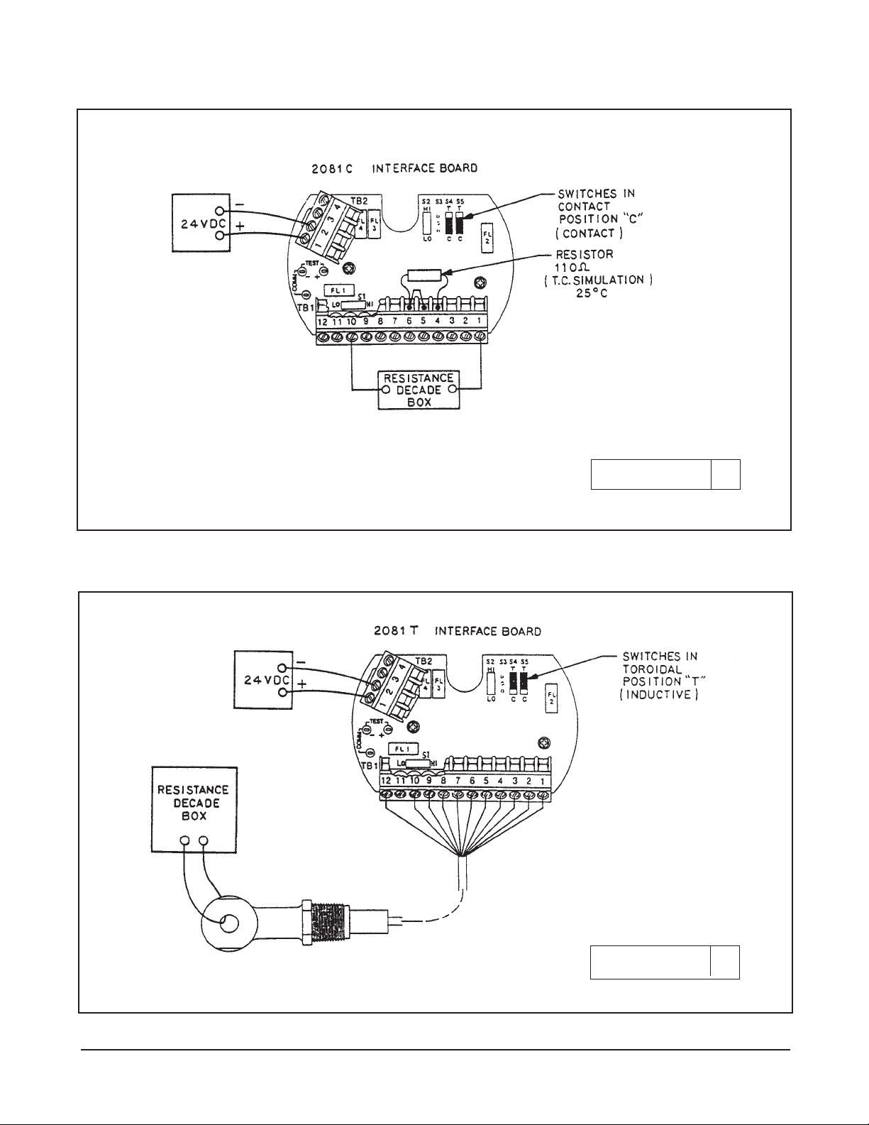
6.2 CONTACT CONDUCTIVITY MODE BENCH
CHECK: Sensor simulation may be used to check the
operation of the model 2081C/T. See Figure 6-1 for
wiring diagram to perform analyzer check.
CAUTION
Do not use over 55 volts to check the loop.
Damage to the transmitter may result.
1. Set up transmitter as shown in Figure 6-1.
2. Simulate a conductivity value by choosing a typical resistance value from Table 6-3 and entering
this resistance value into the decade box.
TABLE 6-3. Resistance Values (Conductivity)
NOTE
Chart assumes a cell constant of 1.0.
Therefore, Resistance = 1/Conductivity.
3. Apply power to the Loop.
4. Set the CELL constant to 1.00.
5. Set the atc to USEr. Enter the user value of 25° C.
(This eliminates temperature condition.)
6. Remove one test lead from the resistance decade
box to simulate 0.00 Microsiemens.
7. Select the zero function -0- from the Level 1
menu.
8. The display will flash -0- while the unit zeros.
9. Reconnect the test lead to the decade box to simulate full-scale conductivity.
10. If calibrated, the display should read close to the
full-scale conductivity value.
11. Scroll to Std and enter the desired full-scale conductivity value
12. Check half-scale reading by doubling the resistance value entered into the decade box.
13. The transmitter conductivity circuitry is operating
correctly if it will zero, read the full-scale and halfscale conductivity values.
Simulate Full Scale
Conductivity Of:
20 microsiemens
200 microsiemens
2000 microsiemens
20,000 microsiemens
Resistance Value
To Use:
50,000 ohms
5,000 ohms
500 ohms
50 ohms
Temperature Resistance
0
0
C 100.00 Ohms
100C 103.90 Ohms
200C 107.90 Ohms
300C 111.67 Ohms
400C 115.54 Ohms
500C 119.40 Ohms
600C 123.24 Ohms
700C 127.07 Ohms
800C 130.89 Ohms
900C 134.70 Ohms
1000C 138.50 Ohms
MODEL 2081C/T SECTION 6.0
DIAGNOSTICS AND TROUBLESHOOTING
Page 29

25
6.3 TOROIDAL CONDUCTIVITY MODE BENCH
CHECK: Sensor simulation may be used to check the
operation of the Model 2081C/T. See Figure 6-2 for
wiring diagram to perform analyzer check.
CAUTION
Do not use over 55 volts to check the loop.
Damage to the transmitter may result.
1. Set up transmitter as shown in Figure 6-2.
2. Simulate a full scale conductivity value by choosing a typical resistance value from Table 6-3 and
entering this resistance value into the decade box.
TABLE 6-3. Resistance Values (Conductivity)
NOTE
Chart assumes a cell constant of 1.0.
Therefore, Resistance = 1/Conductivity.
3. Apply power to the Loop.
4. Set the CELL constant to 1.00.
5. Set the atc to USEr. Enter the user value of 25° C.
(This eliminates temperature correction.)
6. Remove one test lead from the resistance decade
box to simulate 0.00 Microsiemens.
7. Select the zero function -0- from the Level 1
menu.
8. The display will Flash -0- while the unit zeros.
9. Reconnect the test lead to the decade box to simulate full-scale conductivity.
10. If calibrated, the display should read close to the
full-scale conductivity value.
11. Scroll to Std and enter the desired full-scale conductivity value.
12. Check half-scale reading by doubling the resistance value entered into the decade box.
13. The transmitter conductivity circuitry and the sensor are operating correctly if it will zero, read the
full-scale and half-scale conductivity value. If not,
refer to the appropriate sensor instruction manual
to perform tests on the toroidal sensor. If the sensor tests O.K, then replace the transmitters electronic stack.
6.4 SYSTEMATIC TROUBLESHOOTING.
Not all problems that you encounter will be typical. If
you are unable to resolve your problem using the
Quick Troubleshooting Guide, Table 6-4, then try the
step-by-step approach offered in Figure 6-3.
Simulate Full Scale
Conductivity Of:
20 microsiemens
200 microsiemens
2000 microsiemens
20,000 microsiemens
Resistance Value
To Use:
50,000 ohms
5,000 ohms
500 ohms
50 ohms
MODEL 2081C/T SECTION 6.0
DIAGNOSTICS AND TROUBLESHOOTING
Page 30
26
FIGURE 6-1. Bench Check (Contact Sensor)
FIGURE 6-2. Bench Check (Toroidal Sensor)
DWG. NO. REV.
40208113 B
DWG. NO. REV.
40208113 B
MODEL 2081C/T SECTION 6.0
DIAGNOSTICS AND TROUBLESHOOTING
Page 31

27
SYMPTOM PROBLEM ACTION
fct below 0.5 or above 2.0. 1. Old or coated sensor. 1. Clean or replace glass electrode.
Actual range determined by user. 2.
A preceding standardization was incorrect.
Value locks up (no change of 1. Incorrect wiring. 1. Verify wiring.
reading in different standards). 2. Open sensor. 2. Perform sensor checks.
3. Replace sensor.
2081C/T value not the same as 1. Grab sample incorrect. 1. Re-evaluate sample technique and
grab sample of process. equipment.
2. Unclear what is correct. 2. Test with standard solution.
3. 2081C/T out of calibration. 3.
Recalibrate per start-up and calibration sections.
Fault Code TEnP-Lo, or 1. Incorrect wiring. 1. Check wiring between the sensor and the
TEnP-Hi transmitter.
2. Open or shorted RTD. 2. Replace RTD or sensor.
3. Manual temperature 3. Appropriate resistor must be in place mode. TB1-6 to 8. See Table 6-2.
Zero Conductivity reading. 1. Sensor wired incorrectly. 1. Repair wire connection.
2. Solids coating sensor. 2. Clean sensor.
3. Open wire in sensor. 3. Replace sensor.
Fault code rn9E-LOOP. 1. Process value is outside 1. Return process to normal. Check
4-20 mA range points. grab sample.
Fault Code FAIL. 1.Range selection switches 1. Calculate the maximum low range value
S1 and S2 are set and set the switches accordingly. See
incorrectly. Section 1.3.3.
2. Defective PCB stack. 2. Reconnect power or if necessary,
replace PCB stack.
No output current. 1. Defective PCB stack. 1. Replace PCB stack.
2. Incorrect wiring. 2. Check for short.
Low output current. 1. Circuit loading with excess- 1. consult output loading limits 2081C/T
sive resistance on output. specifications (1840 ohms max load).
Drifting or Unstable readings. 1. Air bubbles in process 1. Mount sensor to decrease exposure to
affecting reading. air bubbles.
2. Electrical or grounding 2. Verify sensor works in a standard soluinterference. tion outside of the process.
3.
Verify near by vendor pumps are properly
grounded.
4. Verify that sensor shield never touches
an Earth ground.
5. Run sensor cable though grounded
metal conduit to reduce RFI effects.
Fault code "LOOP" flashing inter- 1. Model 268 or other host 1. Model 268 or other host can return
mittently with Conductivity and has set the output to a transmitter to normal operation.
output value. specific value.
Can't calibrate new sensor. 1. Wrong sensor for meas- 1. Verify that cell content is correct for the
urement range. measurement range.
2. Sensor incompatible with 2. Verify sensor has a PT-100 temperature
analyzer. compensator.
Transmitter won't 1. Incorrect wiring. 1.
Check wiring and model 268 connections.
communicate. 2. Insufficient load resistance. 2. Verify minimum of 500 Ohm loop
resistance.
3. Electronics failure. 3. Replace electronic stack.
TABLE 6-4. Quick Troubleshooting Guide
MODEL 2081C/T SECTION 6.0
DIAGNOSTICS AND TROUBLESHOOTING
Page 32

FIGURE 6-3. TROUBLE SHOOTING FLOW CHART
28
Conductivity Measurement
Problem (in the process)
Remove sensor from process and
place sensor in air. Zero instrument. Refer to Section 4.4.
OK?
OK?
Place sensor in process and
standardize. Refer to Section 4.6
Check wiring again
for short/open
NOTE:
Before starting this procedure make
sure that all wiring is correct.
YES
YES
NO
NO
Does problem
still exist?
YES
NO
Check diagnostic
messages
Refer to Table 6-1
Restart
Analyzer
Check for ground
loops and/or improp-
er installation
Remove sensor from process and
test in known conductivity solution
OK?
Refer to Sensor man-
ual for sensor checks
Verify earth ground is not connect-
ed to sensor shields
Isolate sensor shield from any ground metal (conduit)
Consult service center
Check T.S. Guide
Table 6-4
Verify transmitter
operation with bench
check procedures
Section 6.2 & 6.3
YES
NO
MODEL 2081C/T SECTION 6.0
DIAGNOSTICS AND TROUBLESHOOTING
Page 33
29
7.1 GENERAL: Conductivity is the conductance per
unit of length. The 2081C/T measures and calculates
conductivity using the relation ship I=GV. Where:
G = conductance,
V = the reference voltage, and,
I = the resultant current directly proportional to
conductance.
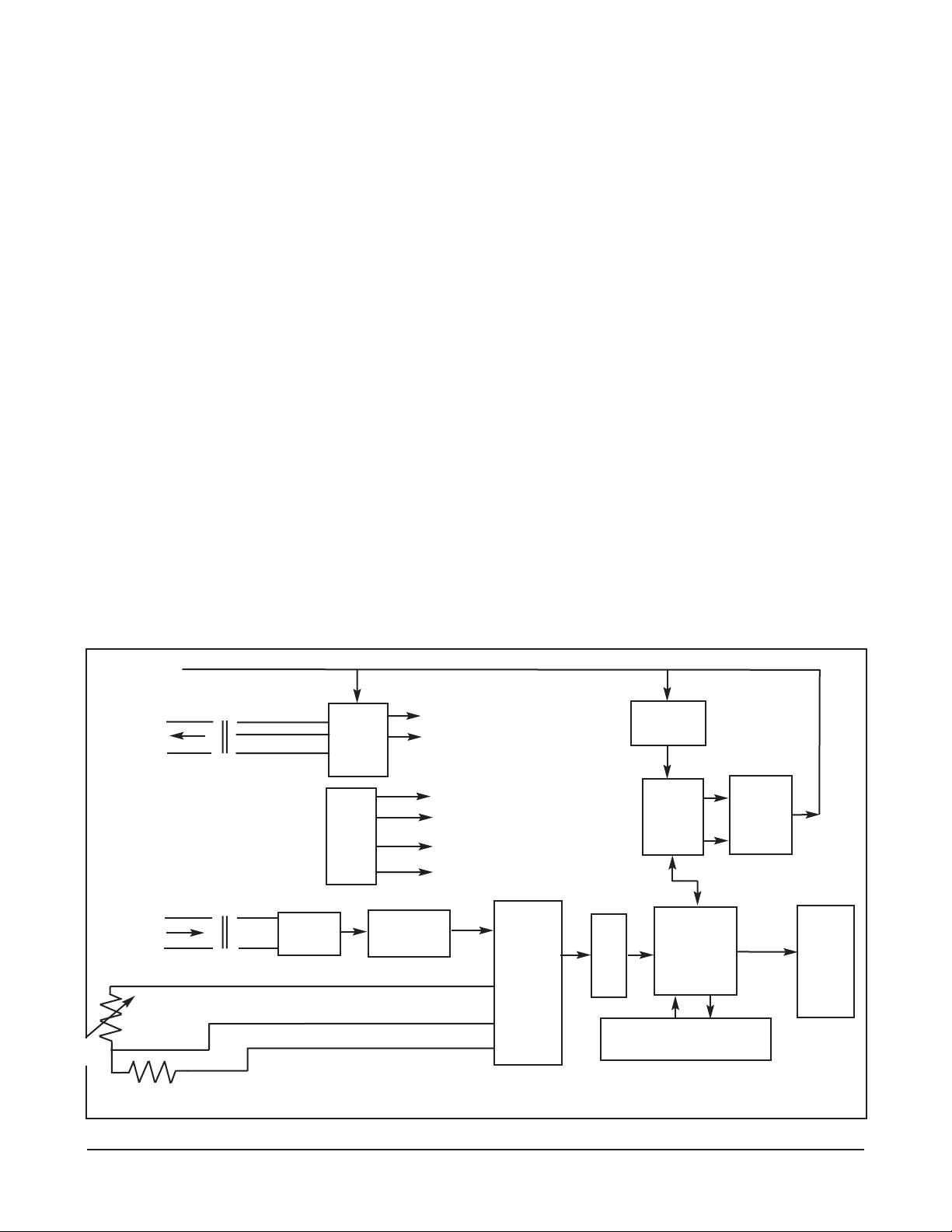
7.2. OVERVIEW: Refer to Figure 7-1 2081C/T Block
Diagram.
Power Supply: Power for the 2081C/T is derived from
the +12 to 55 volt DC loop power. This power is dropped
to a regulated +9 volts DC and maintained by comparison with the output of a 2.5 volt op-amp comparator.
The 9 volts DC is switched by a 28.8 KHz square wave
signal from the Oscillator across the center tapped primary of the drive transformer. This provides the raw 4.5
VAC for the 4.5 Volt DC power supply.
The 28.8 KHz square wave signal from the oscillator
also develops an AC at the secondary that is used to
drive a toroidal (or contacting) conductivity sensor.
When a contacting conductivity sensor is used this isolates the 2081C/T electronics from the process, and
the AC signal also prevents polarizing of the fluid surrounding a contacting conductivity sensor.
Oscillator: The 1.8432 MHz oscillator output is divided
down to provide:
1. a 921.6 KHz CPU clock signal.
2 a 460.8 KHz MODAC clock signal.
3 a 57.6 KHz demodulator sample signal.
4. the 28.8 KHz transformer drive signal.
Input Signals: RTD and sensed cable line voltages
appear at an input to the Mux. These voltages are
converted to digital values by the A/D circuits, and stored
by the CPU. The CPU subtracts the unwanted cable voltage from the RTD voltage and uses these readings with
a reference voltage to calculate the sensor temperature.
This value is used to compensate the absolute conductivity using the temperature slope of the liquid, and can be
sent to the LCD to be displayed.
1. Sensors: This transmitter can be used with either
type of sensor. Contacting or Toroidal inductive).
•
Power &
28.8
KHz
Drive
Osc.
and
Divider
Preamp
Demodulate
& Auto-Zero
Mux
A/D
CPU
ROM
Display
Drivers
DAC
MODAC
Modem
4 to 20
mA
Current
Loop
Summer
HART
Input Filter
+12 to 55 Volts
Loop Power &
HART Comm
Conductivity
Probe Out
(Toroidal or
contacting
Conductivity
Probe In
(Toroidal or
contacting)
PT
100
RTD
Receive
Transformer
RTD source
RTD return
)(
)(
)(
)(
)(
)(
Drive Transformer
+ 9 Volts
+ 4.5 Volts
921.6 KHz (CPU Clock)
460.8 KHz (MODAC Clock)
57.6 KHz (Sample)
28.8 KHz (Drive)
Sense Line
SECTION 7.0 THEORY OF OPERATION
Figure 7-1. Block Diagram
MODEL 2081C/T SECTION 7.0
THEORY OF OPERATION
Page 34

30
Sensors: This transmitter can be used with either type
of sensor. Contacting or toroidal (inductive). Currents
developed by the conductivity probe through the
Receive Transformer are converted to a voltage and
amplified by the preamplifier block. This voltage is
demodulated (in the demodulate and auto-zero block)
in phase with the transmitter toroid resulting in a DC
voltage representing the absolute conductivity.
a. Contact Conductivity Probe. In the contacting sen-
sor, the area and distance between the two electrodes
determine a cell constant, the volume of fluid between
the electrodes acts as a resistor whose value
depends on the conductance of the fluid.
b. Toroidal Conductivity Sensor. Consists of two
independent transformers that have a common
turn, the path of the liquid. The transmitter toroid,
or driver, induces a voltage in the path of the liquid
which is the voltage across the toroid winding
divided by the number of turns in the winding. The
voltage times the conductance results in a current
that is proportional to the conductance. This current is sensed by the receiver toroid. The current
out of this toroid is the current in the liquid loop
divided by the number of turns in its winding. The
result is I = G*V/(N1*N2), where:
N1 is the number of turns of the transmitter toroid.
N2 is the number of turns of the receiver toroid.
V is the voltage across the receive transformer.
G is the conductance of the liquid loop.
I is the resultant current developed in the receiver
transformer by the receive toroid.
HART communication signals. Super-imposed on the
4 to 20 mA current loop, are passed through the HART
Input filter (to reduce noise). This FSK signal is then
demodulate by the MODAC ASIC (Application Specific
Integrated Circuit) and sent on to the CPU via the
MODAC. A FSK signal is an AC signal, whose frequency is shifted higher or lower depending on the
condition of the digital signal (High or Low), This
Frequency Shift Keying is mixed with the DC value of
the 4 to 20 mA signal, using Bell 202 protocol. This
communication conforms to the Rosemount HART
specification and may be used to configure and interrogate the transmitter.
CPU: A 68HC11 micro controller computer chip contains
the central processing unit (CPU). This chip also contains
volatile Random Access Memory (RAM) and nonvolatile
Electrically Erasable Programmable Read Only Memory
(EEPROM). CPU instructions, however, are stored in an
external ROM. The CPU communicates with this external
ROM, Mux, Analog to Digital (A/D) converter, the two
push buttons on the side of the 2081C/T, and the Model
275 Smart Interface through the MODAC. It also controls
the display drivers,
When requested by the CPU the input signals from
either the Contacting or Toroidal sensor are zeroed
and scaled between user supplied setpoints to determine what the proportional current value of the 4 to 20
mA loop should be. This value is sent to control the
Digital to Analog Converter (DAC) in the MODAC
ASIC. The MODAC also produces a weighted Pulse
Width Modulated output representing digital information generated by the CPU to communicate with other
digital devices on the current loop. Both of these signals are sent to the current loop summer. The summer
then mixes this PWM signal with the current loop value
to produce the correct 4 to 20 mA output value for the
transmitter.
MODEL 2081C/T SECTION 7.0
THEORY OF OPERATION
Page 35

31
SECTION 8.0 DESCRIPTION AND SPECIFICATIONS
• UTILIZES EITHER CONTACTING OR INDUCTIVE CONDUCTIVITY SENSORS to meet a
wide range of application requirements.
• FIELD MOUNTED TRANSMITTER ideal for central data processing and control.
• MEMBER OF THE ROSEMOUNT SMART FAMILY
®
.
• LOCAL, PUSH-BUTTON INTERFACE for convenient calibration and range adjustment.
• WEATHERPROOF, CORROSION-RESISTANT ENCLOSURE.
• CONTINUOUS DIAGNOSTICS drive the output to a jumper-selectable high or low value in
the event of a failure.
• HOLD OUTPUT MODE for manual control during sensor maintenance.
8.1 FEATURES
The Model 2081 C Smart Transmitters, with the appropriate sensor, are designed to continuously measure
contacting, toroidal, or conductivity in industrial and
municipal processes. These two-wire transmitters are
members of the Rosemount SMART FAMILY of instruments, which are designed to communicate with the
hand-held Model 275 SMART FAMILY Interface and
any other hosts that support the HART®communications protocol. See Figure 8-1. The Model 2081 design
permits remote configuration, interrogation, testing,
and diagnostics.
The Model 2081 C features an easy-to-use, dual pushbutton interface on the transmitter housing for local calibration and range adjustment. The LCD display indicates the conductivity value as well as temperature,
current output value, range values, temperature slope,
and fault messages. Unauthorized adjustments may be
prevented by a jumper-selectable setting on a circuit
board. All functions are microprocessor based.
The isolated 4-20 mA output is continuously expandable over the measurement range, and may be displayed in either milliamps or percent of full scale. A hold
output function is available for manual control during
routine sensor maintenance. While in hold mode the
current output signal (refer to Table 1) will remain constant at the last current value.
In the event of a failure, the transmitter diagnostic routine will drive the output below 4 mA or above 20 mA
(user selectable) in addition to displaying a fault code
on the transmitter. This routine alerts the user to errors
due to temperature slope, faulty temperature compensation element, open wiring and transmitter electronics
failure. The transmitter will also go into a fault mode if
the conductivity value is outside the output range settings.
With a two-point calibration, the transmitter automatically calculates the temperature slope and the cell constant. On-line standardization is easily accomplished
by simply entering the conductivity value of a grab sample into the transmitter. The transmitter uses a Pt100
RTD signal from the sensor to reference the conductivity reading to 25°C.
The Model 2081 C transmitter is designed to be weatherproof and corrosion resistant to meet NEMA 4X
(IP65) standards. An optional pipe or wall mounting
bracket is available.
The transmitter communicates via the HART®protocol,
which uses an industry standard BELL 202 frequency
shift keying (FSK) technique. Communication is
accomplished by superimposing a digital signal on top
of the 4-20 mA output signal. The Rosemount implementation of this technique allows simultaneous communication and output without compromising loop
integrity.
The Model 2081 requires an external power supply
such as the Model 515 Isolated Power Supply or DC
loop power from a distributed control system. The
Model 515 Power Supply provides power for up to 10
transmitters. Two transmitters may be wired directly to
the power supply. For more than two transmitters, junction boxes are available, each accommodating wiring
for a maximum of ten transmitters.
Remote alarms with independently adjustable setpoints
and hysteresis are available in the Model 230A Alarm
Module. Contacts of the Model 230A may be specified
for high/low, high/high, or low/low operation.
MODEL 2081C/T SECTION 8.0
DESCRIPTION AND SPECIFICATIONS
Page 36
32
8.2 FUNCTIONAL SPECIFICATIONS
Output: Two-wire 4-20 mA with superimposed HART
digital signal.
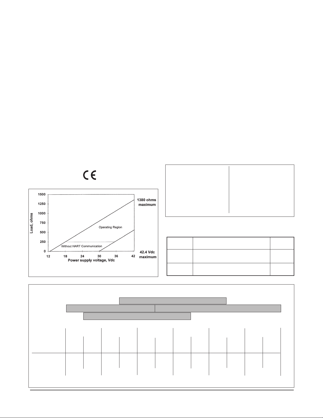
Power Supply and Load Requirements: See Figure
8-1 below. A minimum loop resistance (load) of
250 ohms and minimum power supply voltage of
18 volts DC is required for digital communication.
Local Indication: Four digit LCD
Ambient Temperature: –30 to 70°C (–22 to 158°F)
Failure Mode Alarm: The analog signal will be driven
either below 4 mA or above 20 mA (user-selectable)
Transmitter Security: Security activation (by internal
jumper) prevents changes to the transmitter configuration from the local interface.
Relative Humidity : 0-95%
Automatic Temperature Compensation: Pt100 RTD
0 to 200°C (32 to 392°F)
Enclosure: Weatherproof and corrosion-resistant,
explosion proof
EMI/RFI: EN-61326
8.3 PERFORMANCE SPECIFICATIONS
Range*: See Table 8-2
Output Scale: Zero Suppression: Up to 90% of full
scale
Span: From 10 to 100% of full scale
Accuracy: ±0.5% full scale @ 25°C
Resolution: 0.1% full scale, 0.1°C
Repeatability: ±0.25% full scale
Stability: 1%/ year at 25°C
Temperature Effect: 0.02% F.S./°C
Vibration Effect: ±1.0% of F.S. per SAMA PMC
31.1
* Not applicable for ultra pure water applications. See the
products data sheets for Model 3081C/81C or Model
1054B LC for these applications.
• Display output in mA/% of full
scale
• Hold output mode
• Set 4-20 mA output range
• Display temperature in °C/°F
• Input or display cell constant
• Display cell factor
• Electronic zero
• Auto/manual temperature
compensation
• Two point calibration
• Standardize temperature
• Standardize conductivity
• Input or display temperature
slope
• Display absolute conductivity
TABLE 8-1. Local Interface Functions
TABLE 8-2. Measurement Ranges
FIGURE 8-1. Load/Power Supply Requirements
MODEL 2081C/T SECTION 8.0
DESCRIPTION AND SPECIFICATIONS
Type Maximum Switch
Sensor Range Setting
Toroidal Below 400,000µS x Cell Constant Both “Lo”
Above 400,000µS x Cell Constant Both “Hi”
Contacting Below 4,000µS x Cell Constant Both “Lo”
Above 4,000µS x Cell Constant Both “Hi”
Resistivity
(Ω-cm)
Conductivity
(µS/cm)
.05kΩ
20,000µS
2,000µS
500µS
200µS
100µS
20µS
10µS
2µS
1µS
.2µS
.1µS
.05µS
.02µS
.5kΩ
2kΩ
5kΩ
10kΩ
50kΩ
100kΩ
500kΩ
1MΩ
5MΩ
10MΩ
20MΩ
50MΩ
Operating Ranges for Various Contacting Cells Constants (not to scale)
1.0 cm
-1
10.0 cm
-1
0.01 cm
-1
0.1 cm
-1
Page 37

33
8.4 PHYSICAL SPECIFICATIONS
Electrical Connections: 1/2 in. NPT.
Model 275 SMART FAMILY Interface connections
permanently fixed to terminal block. The terminal
block also has removable connectors for bare wire
sensor connections.
Housing: Epoxy-polyester painted over low
coppercast aluminum. BUNA-N O-rings on
cover.
Recommended Cable: Transmitter to power supply
two-wire, 18 AWG, shielded, Belden 8760 or
equal (Rosemount Analytical PN 9200001).
Weight/Shipping Weight: 2.18 kg/2.68 kg (4.8 lb/5.9 lb)
Hazardous Area Classification:
FM Certification:
Type Class Div. Groups
I.S. I, II, III I ABCDEFG
Dust/Ignition II, III I EFG
N.I. I 2 ABCD
CENELEC Certification*:
Contacting Conductivity-
I.S. EEXia IIC T5 (Tamb = 40°C) or
EEXia IIC T4 (Tamb = 70°C)
Toroidal Conductivity- I.S. same specifications
* user must specify sensor type in order to receive an
Intrinsically safe loop
8.5 RECOMMENDED SENSORS:
(CONTACTING)
Model 140 Retractable Conductivity
Model 141/142 Insertion Conductivity
Model 150 Insertion/Submersion Conductivity
Model 400 Screw-In Low Conductivity
Model 401 Screw-In High Conductivity
INDUCTIVE FULL SCALE
Minimum Maximum
Model 222 Sensor 0-500 µS/cm 0-2000 mS/cm
Model 226 Sensor 0-50 µS/cm 0-1000 mS/cm
Model 225 Sensor 0-250 µS/cm 0-2000 mS/cm
Model 228 Sensor 0-250 µS/cm 0-2000 mS/cm
MODEL 2081C/T SECTION 8.0
DESCRIPTION AND SPECIFICATIONS
NOTE: Not applicable for conductivity less than 10 mS/cm. For these applications, please
see product data sheets for Models 1054BLC, 1055C, or 3081/81C.
CONTACTING SENSORS
Conductivity Sensor 142 142 140, 141 401-14
Model Number 400 150 150 402/403
402/403/404 400/402/403/404 400/402/403
Cell Constant 0.01 0.1 1.0 10.0
FULL SCALE MICROSIEMENS/cm
INDUCTIVE SENSORS
Conductivity Sensor
Model Number 226 228 225 222 (1in.) 222 (2 in.)
Cell Constant* 1.0 3.0 3.0 6.0 4.0
Minimum Range 50 250 250 500 500
Maximum Range 1,000,000 2,000,000 2,000,000 2,000,000 2,000,000
* Typical
Page 38

34
8.6 ORDERING INFORMATION
2081C/T 67 EXAMPLE
Code Input (Required selection)
C Contacting Conductivity
T Toroidal Conductivity
Code Options
11 Stainless steel tag (specify marking)
Code Agency Approvals
67 FM approved, Intrinsically Safe (when used with approved sensor and safety barrier) and
explosion-proof, Contacting and Toroidal
69 CSA approved, Intrinsically Safe (when used with approved sensor and safety barrier) and
explosion-proof, Contacting and Toroidal
73 CENELEC approved, Intrinsically Safe (safety barrier required), Contacting and Toroidal
MODEL
2081 HART SMART TWO-WIRE CONDUCTIVITY TRANSMITTER
Model 2081C/T conductivity Two-Wire Transmitter is compatible with both contacting and inductive conductiv-
ity sensors (indicate sensor type if known). It is housed in a NEMA 4X (IP65) weatherproof, corrosion-resistant
enclosure suitable for pipe mounting. Standard features include HART digital communications capability, LCD
digital display, isolated 4-20 mA output, and automatic temperature compensation.
PN DESCRIPTION RECOMMENDED SPARES
23419-00 PCB, 2081 LCD Display 1
23533-00 PCB, 2081 Interface
23421-02 PCB Stack, 2081C (CPU/Sensor loop and display) 1
23421-03 PCB Stack, 2081T (Sensor loop and display)
23519-00 Push Buttons, 2081, Kit 1
33197-00 Enclosure, Middle
2002518 Enclosure Cover, LCD Display Side
2002577 Pipe Mounting Bracket
2002603 O-ring Kit (Qty 2), Window
2002604 O-ring Kit (Qty 2), Enclosure 2
3002468 Enclosure Cover, Tall
9200001 Cable, 2 Conductor, 18 AWG, Shielded
9240008-00 Overlay, 2081pH LCD Display 1
9240864 Stainless steel tag (formerly Code -07)
8.7 ACCESSORIES
MODEL 2081C/T SECTION 8.0
DESCRIPTION AND SPECIFICATIONS
Page 39

35
FIGURE 8-2. MODEL 275 HART COMMUNICATION MENU TREE- MODEL 2081C
MODEL 2081C/T SECTION 8.0
DESCRIPTION AND SPECIFICATIONS
Page 40

SECTION 9.0 RETURN OF MATERIAL
9.1 GENERAL.
To expedite the repair and return of instruments, proper
communication between the customer and the factory
is important. Call 1-949-757-8500 for a Return
Materials Authorization (RMA) number.
9.2 WARRANTY REPAIR.
The following is the procedure for returning instruments still under warranty:
1. Call Rosemount Analytical for authorization.
2. To verify warranty, supply the factory sales order
number or the original purchase order number. In
the case of individual parts or sub-assemblies, the
serial number on the unit must be supplied.
3. Carefully package the materials and enclose your
“Letter of Transmittal” (see Warranty). If possible,
pack the materials in the same manner as they
were received.
4. Send the package prepaid to:
Rosemount Analytical Inc., Uniloc Division
Uniloc Division
2400 Barranca Parkway
Irvine, CA 92606
Attn: Factory Repair
RMA No. ____________
Mark the package: Returned for Repair
Model No. ____
9.3 NON-WARRANTY REPAIR.
The following is the procedure for returning for repair
instruments that are no longer under warranty:
1. Call Rosemount Analytical for authorization.
2. Supply the purchase order number, and make
sure to provide the name and telephone number
of the individual to be contacted should additional
information be needed.
3. Do Steps 3 and 4 of Section 9.2.
NOTE
Consult the factory for additional information regarding service or repair.
MODEL 2081C/T SECTION 9.0
RETURN OF MATERIAL
36
Page 41

WARRANTY
Seller warrants that the firmware will execute the programming instructions provided by Seller, and that the Goods manufactured
or Services provided by Seller will be free from defects in materials or workmanship under normal use and care until the expiration of the applicable warranty period. Goods are warranted for twelve (12) months from the date of initial installation or eighteen
(18) months from the date of shipment by Seller, whichever period expires first. Consumables, such as glass electrodes,
membranes, liquid junctions, electrolyte, o-rings, catalytic beads, etc., and Services are warranted for a period of 90
days from the date of shipment or provision.
Products purchased by Seller from a third party for resale to Buyer ("Resale Products") shall carry only the warranty extended by
the original manufacturer. Buyer agrees that Seller has no liability for Resale Products beyond making a reasonable commercial
effort to arrange for procurement and shipping of the Resale Products.
If Buyer discovers any warranty defects and notifies Seller thereof in writing during the applicable warranty period, Seller shall, at
its option, promptly correct any errors that are found by Seller in the firmware or Services, or repair or replace F.O.B. point of manufacture that portion of the Goods or firmware found by Seller to be defective, or refund the purchase price of the defective portion of the Goods/Services.
All replacements or repairs necessitated by inadequate maintenance, normal wear and usage, unsuitable power sources, unsuitable environmental conditions, accident, misuse, improper installation, modification, repair, storage or handling, or any other
cause not the fault of Seller are not covered by this limited warranty, and shall be at Buyer's expense. Seller shall not be obligated to pay any costs or charges incurred by Buyer or any other party except as may be agreed upon in writing in advance by
an authorized Seller representative. All costs of dismantling, reinstallation and freight and the time and expenses of Seller's personnel for site travel and diagnosis under this warranty clause shall be borne by Buyer unless accepted in writing by Seller.
Goods repaired and parts replaced during the warranty period shall be in warranty for the remainder of the original warranty period or ninety (90) days, whichever is longer. This limited warranty is the only warranty made by Seller and can be amended only
in a writing signed by an authorized representative of Seller. Except as otherwise expressly provided in the Agreement, THERE
ARE NO REPRESENTATIONS OR WARRANTIES OF ANY KIND, EXPRESS OR IMPLIED, AS TO MERCHANTABILITY, FITNESS FOR PARTICULAR PURPOSE, OR ANY OTHER MATTER WITH RESPECT TO ANY OF THE GOODS OR SERVICES.
RETURN OF MATERIAL
Material returned for repair, whether in or out of warranty, should be shipped prepaid to:
Emerson Process Management
Liquid Division
2400 Barranca Parkway
Irvine, CA 92606
The shipping container should be marked:
Return for Repair
Model
_______________________________
The returned material should be accompanied by a letter of transmittal which should include the following information (make a
copy of the "Return of Materials Request" found on the last page of the Manual and provide the following thereon):
1. Location type of service, and length of time of service of the device.
2. Description of the faulty operation of the device and the circumstances of the failure.
3. Name and telephone number of the person to contact if there are questions about the returned material.
4. Statement as to whether warranty or non-warranty service is requested.
5. Complete shipping instructions for return of the material.
Adherence to these procedures will expedite handling of the returned material and will prevent unnecessary additional charges
for inspection and testing to determine the problem with the device.
If the material is returned for out-of-warranty repairs, a purchase order for repairs should be enclosed.
Page 42

Credit Cards for U.S. Purchases Only.
The right people,
the right answers,
right now.
ON-LINE ORDERING NOW AVAILABLE ON OUR WEB SITE
http://www.raihome.com
Emerson Process Management
Rosemount Analytical Inc.
2400 Barranca Parkway
Irvine, CA 92606 USA
Tel: (949) 757-8500
Fax: (949) 474-7250
http://www.raihome.com
© Rosemount Analytical Inc. 2003
 Loading...