

Page 1

YARWAY MODEL 20 PNEUMATIC DIAPHRAGM ACTUATOR
INSTALLATION, OPERATION AND MAINTENANCE INSTRUCTIONS
Before installation these instructions must be fully read and understood
PRINCIPLE OF OPERATION
In a direct acting diaphragm actuator,
increasing loading pressure moves the actuator
stem downward, compressing the spring. When
the loading pressure is decreased, the spring
moves the actuator stem upward.
In the event of failure of the loading pressure
or the operating medium pressure to the
controller, the actuator stem moves to the
upward position.
Warning: be certain that the diaphragm casing
pressure does not exceed the limits listed in
the specification table (see table 1).
UNPACKING
The Yarway pneumatic diaphragm actuators
are mostly delivered in combination with
Desuperheaters for use on low-, medium- and
high pressure steam applications and packed
with the greatest care in wooden boxes or
cartons for protection during handling and
transit to site. If it is found, however, that
damage has occurred during shipment, then
this should be reported immediately to your
forwarder or Yarway representative.
Particular care should be taking when
removing the pneumatic diaphragm actuators
(including Desuperheaters) from the packing
and your special attention is required to
check carefully that no damage has occurred
to the actuators, accessories as: pneumatic
positioner, electric/pneumatic positioner,
position transmitter, air filter regulator, booster
relay, lock-in relay, limit switches, solenoid
valves and the standard piping with stainless
steel pipe and fittings.
Warning: the hoisting lug is for the actuator
only, NOT for a total assembly!
www.valves.emerson.com © 2017 Emerson. All rights reserved.
VCIOM-03327-EN 16/10
Page 2
YARWAY MODEL 20 PNEUMATIC DIAPHRAGM ACTUATOR
INSTALLATION, OPERATION AND MAINTENANCE INSTRUCTIONS
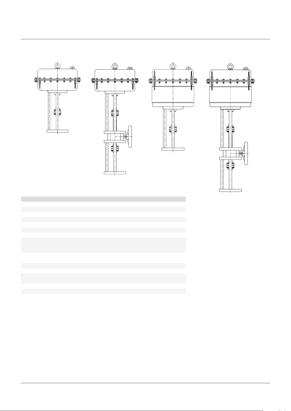
FIGURE 1 FIGURE 2 FIGURE 3 FIGURE 4
20 - 55 20 - 55 20 - 90 20 - 90
TABLE 1 - FUNCTIONAL SPECIFICATIONS
Type 20 - 55 (see fig. 1) 20 - 90 (see fig. 3)
Type Direct acting Direct acting
Action Stem extends with air pressure Stem extends with air pressure
Diaphragm 950 cm
Air displacement 5225 cm
Max. thrust 11 kN (48.800 lbf) 10 kN (44.400 lbf)
Spring range 1.0 to 3.8 bar (15 to 55 psi) 1.0 to 2.2 bar (15 to 32 psi)
Travel 55 mm (2⅛”) 90 mm (3½”)
Travel speed Depending on spring range, air supply
Travel indicator Integrated pointer and stainless steel
Air connection ½” NPT female ½” NPT female
Air supply 6.0 bar (max. 87 psi) 6.0 bar (max. 87 psi)
Ambient temperature
(std)*
Weight 46.0 kg (102 lbs) 68.0 kg (150 lbs)
Handwheel Side mounted (see fig. 2) Side mounted (see fig. 4)
Weight 19.0 kg (42 lbs) 19.0 kg (42 lbs)
Protection level (std)** IP55 IP 55
NOTE
* = Optional temperature: -40°C to +80°C [-40°F to +158°F]
** = Optional protection level: IP66
2
3
pressure, piping arrangement and air
capacity of auxiliary devices
travel scale
-29°C to +70°C (-20°F to +158°F) -29°C to +70°C (-20°F to +158°F)
2
950 cm
3
8550 cm
Depending on spring range, air supply
pressure, piping arrangement and air
capacity of auxiliary devices
Integrated pointer and stainless steel
travel scale
2
Page 3
YARWAY MODEL 20 PNEUMATIC DIAPHRAGM ACTUATOR
INSTALLATION, OPERATION AND MAINTENANCE INSTRUCTIONS
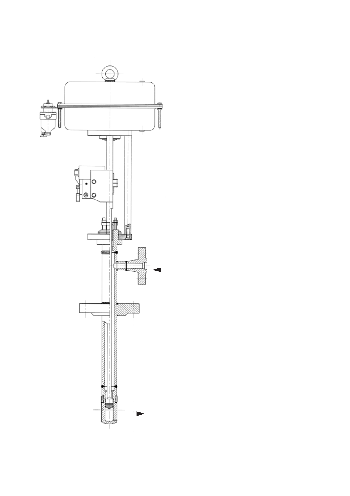
FIGURE 5
Air filter regulator
E/P-postioner
Water inlet
Water outlet
Assembly of a ‘Yarway’ standard duty A.T.-Temp Desuperheater
3
Page 4

YARWAY MODEL 20 PNEUMATIC DIAPHRAGM ACTUATOR
INSTALLATION, OPERATION AND MAINTENANCE INSTRUCTIONS
ACTUATOR/DESUPERHEATER DISASSEMBLY
(SEE FIG. 6 AND 7)
Before any maintenance operation on the
Yarway Desuperheater fitted with a Yarway
actuator model 20 - 55/20 - 90, please
carefullyfollow these instructions:
• Isolate or bypass the steam supply.
• Check steam line is cooled down and
pressure free.
• Shut-off Desuperheater water supply.
1. Cut-off the air supply to the positioner
via the air filter regulator. Disconnect the
pneumatic connections and the electrical
connections of the positioner on the
network. Disassemble on the actuator side
the pneumatic connections to the positioner.
2. Disconnect the lever of the positioner from
the stem coupling (mechanical linkage).
3. Slightly supply the actuator to lift the
Desuperheater piston from the seat.
Disassemble the upper and lower
couplings(27) (see fig. 6 and 7) through
the screws. Cut-off the air on the
diaphragmcasing.
4. Unscrew the lock nut (see Installation,
Operation and Maintenance Manual of the
A.T.-Temp Desuperheater) and lift the entire
actuator from the Desuperheater.
DISASSEMBLY
Diaphragm exchange
• Cut-off the air supply to the positioner via the
air filter regulator. Disconnect the pneumatic
connections and the electrical connections of
the positioner on the network. Disassemble
on the actuator side the pneumatic
connections to the positioner.
• Remove all short bolts (18), rings (21) and
nuts (20) on the bolt circle. Progressively
unscrew the 4 long bolts (19), located on
a quadrangle on the circle, to unload the
springs. After having released the 4 bolts,
take the upper casing (1) away.
• Unscrew plate bolt (3) whilst avoiding
the actuator stem (10) rotation by using
the square located on the half upper
coupling(27). Take diaphragm plate (4)
away. Withdraw diaphragm (5) and replace
it by a new one. Tighten diaphragm plate by
applying160 Nm on bolt (3).
• Reassemble the upper casing by using the
4 bolts (19), load the springs until complete
tightening of the diaphragm and complete the
short bolts circle in a clockwise, criss-cross
pattern with a max. torque of 40 Nm.
Exchange of one or more springs
• Same instructions as for diaphragm
exchange, except spring plate (6) has to
betaken away.
• Change damaged springs (7/8) and
reassemble in the opposite way.
This operation is only needed for:
• To change the diaphragm.
• To change one or several springs.
TABLE 2 - SPARE PARTS
Model 20 - 55 (fig. 6) Model 20 - 90 (fig. 7)
Item Quantity Name Part no. Item Quantity Name Part no.
3 1 Plate bolt M14 x 100 mm HN-3283
5 1 Diaphragm ø 420 3N-1299-20
6 1 Spring plate 3N-2336
19, 20, 21 Set
7, 8 1 Spring ø 59, 6 black, total 5
1 Spring ø 59, 6 red, total 5
13 1
1
4 x bolts M8 x 100 mm /
4 x nuts M8 / 8 x washers / 8 x nuts M8 / 8 x washers /
4 x protecting tubes 8 x protecting tubes
required per actuator
requiredper actuator
Bushing M35 x 1.5 mm brass 4N-2764-20
Bushing M35 x 1.5 mm GGGN60 4N-3858-20
HN-3118 19, 20, 21 Set
4N-2900-20 7, 8 1 Spring ø 100 (inner), total 3
4N-3416-20 1 Spring ø 140 (outer), total 3
3 1
5 1
6 1
13 1
Plate bolt M14 x 100 mm HN-3283
Diaphragm ø 420 3N-1299-20
Spring plate 3N-2286-20
4 x bolts M8 x 160 mm /
required per actuator
required per actuator
Bushing M35 x 1.5 mm brass
1
Bushing M35 x 1.5 mm GGGN60
HN-3117
4N-3017-20
4N-3016-20
4N-2764-20
4N-3858-20
Make sure that the identification number (indicated on the nameplate) is verified and specified when ordering spare parts.
4
Page 5

YARWAY MODEL 20 PNEUMATIC DIAPHRAGM ACTUATOR
INSTALLATION, OPERATION AND MAINTENANCE INSTRUCTIONS
FIGURE 6
MODEL 20 - 55
95
55
9544400
ø 420
ø 360
•
16
•
21
25
23
22
24
•
•
•
•
26
17
•
•
•
•
•
•
5
7
19 27
1
2
3
4
18
6
20
8
12
15
13
10
14
•
•
•
•
•
•
•
•
•
•
28
•
TABLE 3 - STANDARD MATERIALS
Item Qty. Name Material Dimension Item Qty. Name Material Dimension
1 1 Upper housing C-steel 16 1 ½” NPT socket A105 / C22.8
2 1 Limit block C-steel 17 1 Hoisting lug C-steel
3• 1 Bolt 12.9 M14 x 100 mm 18* 16 Bolt 8.8 M8 x 30 mm
4 1 Diaphragm plate C-steel 19*• 4 Bolt 8.8 M8 x 100 mm
5• 1 Diaphragm Rubber 20* 16 Nut Steel M8
6 1 Spring plate Aluminium 21* 4 Washer C-steel
7• 5 Spring right 22 1 Cushioning plate Rubber
8• 5 Spring left 23 1 Support plate Aluminium
10 1 Stem A182 F316 24 2 Connector air snubber St. steel
12 1 Lower housing C-steel 25* 1 Washer C-steel M14
13• 1 Bushing Brass / GGGN60+ 26 2 Air snubber Brass
14* 3 Yoke pillar C-steel 27* 4 Nut 3D 8.8 M8
15 1 Yoke plate actuator A105 / C22.8 28 3 Bolt 8.8 M12 x 40
NOTES
- Dimensions may be subject to change without prior notification.
- Yarway will provide a certified dimensional drawing upon request.
- Bolts nr. 19 are used for disassembly of actuator and provided with protection tube.
* Zinc plated parts
+ Optional
• Recommended spares
5
Page 6

YARWAY MODEL 20 PNEUMATIC DIAPHRAGM ACTUATOR
INSTALLATION, OPERATION AND MAINTENANCE INSTRUCTIONS
FIGURE 7
MODEL 20 - 90
17
16
1
2
3
4
5
6
25
19 27
•
•
•
•
•
ø 420
ø 360
•
•
•
•
•
9544
•
•
•
18
21
20
7
8
12
11
22
24
26
15
13
10
14
•
•
•
•
•
•
•
•
28
•
•
•
23
•
•
225
400
TABLE 4 - STANDARD MATERIALS
Item Qty. Name Material Dimension Item Qty. Name Material Dimension
1 1 Upper housing C-steel 16 1 ½” NPT socket A105 / C22.8
2 1 Limit block C-steel 17 1 Hoisting lug C-steel
3• 1 Bolt 12.9 M14 x 100 mm 18* 16 Bolt 8.8 M8 x 30 mm
4 1 Diaphragm plate C-steel 19*• 4 Stud 8.8 M8 x 200 mm
5• 1 Diaphragm Rubber 20* 16 Nut Steel M8
6 1 Spring plate Aluminium 21* 8 Washer 8.8 M8
7• 3 Spring inside 22 1 Cushioning plate Rubber
8• 3 Spring outside 23 1 Support plate Aluminium
10 1 Stem A182 F316 24 2 Connector air snubber St. steel
11 1 Stroke limiter A106 Gr. B / ST.35.8 25* 1 Washer 8.8 M14
12 1 Lower housing C-steel 26 2 Air snubber Brass
13• 1 Bushing Brass / GGGN60+ 27* 4 Nut 3D 8.8 M8
14* 3 Yoke pillar C-steel 28 3 Bolt 8.8 M12 x 40
15 1 Yoke plate actuator A105 / C22.8
NOTES
- Dimensions may be subject to change without prior notification.
- Yarway will provide a certified dimensional drawing upon request.
- Bolts nr. 19 are used for disassembly of actuator and provided with protection tube.
* Zinc plated parts
+ Optional
• Recommended spares
6
Page 7

YARWAY MODEL 20 PNEUMATIC DIAPHRAGM ACTUATOR
INSTALLATION, OPERATION AND MAINTENANCE INSTRUCTIONS
FIGURE 8 - SIDE-MOUNTED HANDWHEEL
280
•
5
11
1
•
20
104
10
•
2 17
•
•
24
•
•
•
•
7 16
•
4
•
6
•
•
•
18
•
19
•
23
21 25
150
1193
•
•
•
•
•
8
•
•
•
•
•
12
13
•
22
14
ø 200
15
23
TABLE 5 - STANDARD MATERIALS
Item Qty. Name Material Dimension Item Qty. Name Material Dimension
1* 1 Mounting plate (upper) SA 105 14 1 Parallel key C 45 5 x 5 x 20 mm
2* 1 Mounting plate (lower) SA 105 15• 1 Circlip Steel
3* 1 Mounting plate (handwheel) St 37 K 16• 1 Plain bearing PTFE
4• 1 Drive shaft Al. bronze / GGGN60 17• 1 Bearing bushing Nylon
5 1 Shaft left 1.4057 18* 1 Eye bolt St 37.2
6• 1 Shaft right 1.4057 19 1 Padlock
7*• 1 Helical gear C-steel 20* 2 Pillar SA 105
8* 1 Parallel key C 45 8 x 7 x 24 mm 21 2 Screw St. steel M5 x 10 mm
9*• 1 Pinion C-steel 22 1 Nameplate St. steel
10 1 Cover St. steel 23 1 Handwheel Aluminium
11* 8 Bolt 10.9 M12 x 40 mm 24* 1 Gear bushing SA 106 Gr. B
12* 1 Bushing (handwheel) SA 105 25 2 Ring St. steel M5
13*• 1 Spindle (handwheel) SA 105
NOTES
* Zinc plated parts
• Recommended spares
7
Page 8

YARWAY MODEL 20 PNEUMATIC DIAPHRAGM ACTUATOR
INSTALLATION, OPERATION AND MAINTENANCE INSTRUCTIONS
MAINTENANCE
Maintenance of the Yarway actuator is straight
forward and does not require any special tools
or training.
Care should be taken during any maintenance
operation, particularly when working with
grinders, compressed air and rotating
machinery. It is imperative that safety
glasses and protective workwear are used in
accordance with standard safety procedures.
In case of doubt, consult your supervisor or
safety officer before commencing any work
ontheequipment.
MANUAL OPERATOR
• The Yarway manual operator is side-mounted
between the actuator and the Desuperheater.
• The manual operator is intended to be used
for emergency only.
• The handwheel (23) is locked by means of
apadlock (19).
• The handwheel will not turn during actuated
operation of the actuator assembly and/or
Desuperheater assembly.
• By unlocking the padlock, clockwise turning
the handwheel will move the 2 spindle
parts(5)(6) away from each other, opening
the valve.
• Turning counter clockwise, the valve
willclose.
After using the manual operator, the system
shall be set back to the original position. Failing
to do so may lead to improper valve response
and/or damaging of the piston/spray cylinder.
STORAGE PROCEDURE
Upon receipt, check both the pneumatic
actuator and the packing case for any transit
damage. Any damage to the pneumatic
actuator should be reported immediately to
Yarway or their local agent. Any damage to
the packing container should be rectified to
prevent the ingress of dust or water, prior to
placing the equipment into storage. Check
the information contained on the identification
plate (tagplate) and documentation and return
the unit to its packing with protective covers in
place (seefig.5).
For short term storage, up to 6 months
duration, no additional preservation measures
are necessary. Retain the unit in its original
packing in a clean, dry indoor location.
If outdoor storage is unavoidable, then
the packing case should be enclosed in a
waterproof covering.
For long term storage use a dry indoor location
only. Retain pneumatic actuator in its original
packing and inspect at 3 monthly intervals to
ensure that no deterioration has occurred.
Before placing the pneumatic actuator into
service, inspect all components, to ensure
correct functioning. Follow the procedure for
installation as detailed in the operating and
maintenance instruction manual.
WARNING
The hoisting lug is for the actuator only, NOT for
atotal assembly!
NOTE
NOTES
- Apply some general purpose grease on the
gear wheel (7)(9) once a year.
- Make sure no dirt is trapped between the
drive shaft (4) and the wheel large (7).
- This may obstruct free movement between
these parts.
TABLE 6 - SPARE PARTS
Item Qty Name Part number
7, 9 + 13, 15, 16, 17 1 Spares SM handwheel 4N-4307-20
4, 5, 6 1 Spindle kit SM handwheel Al Bronze 4N-4308-20
4, 5, 6 1 Spindle kit SM handwheel GGGN60 4N-4310-20
Materials and data of units supplied, may
deviated from this Instruction Manual. Please
consult order documents in case of doubt.
The pneumatic actuator is classified under
European Directive 2014/68/EC under
category I with CE-marking and ATEX 2014/34/
EC. See actuator name plate.
© 2017 Emerson. All rights reserved.
8
 Loading...