

Page 1
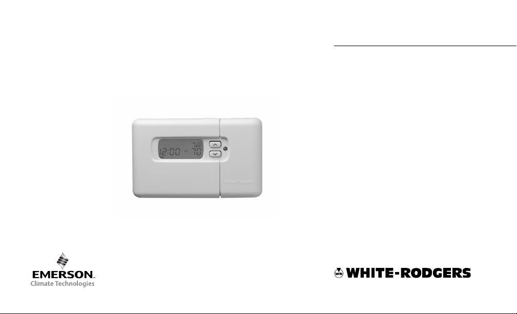
Thermostat/Humidifier Control
Digital 7 Day Programmable
Comfort-Set
®
TM
90 Series
PREMIUM
1F97-391
Installation and
Operating Instructions
Retain for Future Use
Page 2
Easy, Menu-Driven Set-Up
and Programming
1
5
2
4
3
6
7 8
9
10
11
12
Premium options
to customize the thermostat
to fit your application.
17
16
15
14
13
Page 3

INTRODUCTION
Thank you for purchasing your
new Comfort-Set 90 thermostat
and humidifier control. WhiteRodgers has been producing
energy saving controls for over
60 years. We have been designing and producing the ComfortSet family of electronic programmable thermostats since
1982. Comfort-Set 90 is the
third generation of the electronic programmable family.
We believe you will find that
the Comfort-Set 90 is the most
user friendly and technologically advanced thermostat and
humidifier control available
today.
Introduction
Installation/Configuration
You will find information about
thermostat buttons and display
beginning on page 2.
Introduction . . . . . . . . . . . . . . . . . . . . . . . . . .1
Installation/Configuration . . . . . . . . . . . . . . .4
Manual Operation and Programming . . . .24
Features . . . . . . . . . . . . . . . . . . . . . . . . . . . . .30
FAQs . . . . . . . . . . . . . . . . . . . . . . . . . . . . . . . .38
Troubleshooting . . . . . . . . . . . . . . . . . . . . . .42
Index . . . . . . . . . . . . . . . . . . . . . . . . . . . . . . .46
Use the tabs at the bottom of the page to quickly
locate sections
1
Programming
Features
FAQs
Troubleshooting Index
Page 4
INTRODUCTION
THE THE
THERMOSTTHERMOST
THE
THERMOST
THE THE
THERMOSTTHERMOST
See inside front cover for illustration
showing button locations.
1
(Blue arrow) Lowers temperature
setting (45°F or 7°C minimum)
2
(Red arrow) Raises temperature setting
(99°F or 37°C maximum)
3
The yellow indicator glows when the
system is operating.
4
This button (on top of the cover) lights
the display.
5
Used to initiate or review thermostat
programming.
6
Used with TIME
to set the clock.
AA
A
AA
T BT B
T B
T BT B
FWD
UTTUTT
UTT
UTTUTT
/TIME
ONSONS
ONS
ONSONS
BACK
7
Used to adjust the time backward, or to
select the previous menu item.
8
Used to adjust the time forward, or to
select the next menu item.
9
Used with TIME
to set the current day and with
enter VACATION mode.
10
Used to advance operation to the next
program period.
11
Used to manually override program-
ming to hold at a selected temperature.
12
Used to display humidity.
13
Selects fan operation (see The Display,
figure 1 21 ). This button is also used to
program the fan to run continuously during
a program period.
FWD
2
/TIME
HOLD
BACK
to
14
Used to set/reset the filter and
humidity maintenance timer.
15
Sets the system mode (HEATing, OFF,
COOLing, or AUTOmatic changeover).
16
Used to adjust the clock one hour
forward or back.
17
Used to start or return to program
operation.
Page 5
LARLAR
GE LIGHTED (LGE LIGHTED (L
LAR
GE LIGHTED (L
LARLAR
GE LIGHTED (LGE LIGHTED (L
CD) DISPLACD) DISPLA
CD) DISPLA
CD) DISPLACD) DISPLA
The thermostat display alternately shows
the current time and the current temperature on the left side. The display also
shows the temperature you have programmed or set on the right side of your
screen.
18
Displays system mode (
COOLCOOL
AA
UTUT
OO
A
AA
UT
UTUT
HOLDHOLD
O,
HOLD,
OO
HOLDHOLD
MOR,MOR,
MOR,
MOR,MOR,
COOL,
COOLCOOL
HUMDHUMD
HUMD). During programming displays the
HUMDHUMD
time period (
D D
D
D D
AA
A
AA
VV
V
VV
YY
,,
EVE, EVE,
Y
,
EVE,
YY
,,
EVE, EVE,
HEAHEA
HEA
HEAHEA
AA
CA CA
A
CA or
AA
CA CA
TT
OFFOFF
T,
OFF,
TT
OFFOFF
NHT NHT
NHT)
NHT NHT
being programmed. In the configuration
18 18
19 20 21
CHECK BATTERY
MON
2324
FAN AUTOHRS
F
AM
22
YY
Y
YY
menu, the menu item name is shown, one
PRPR
GMGM
word at a time (
COOLCOOL
FF
AN AN
COOL
F
AN
COOLCOOL
FF
AN AN
19
CHECK BCHECK B
CHECK B
CHECK BCHECK B
DELADELA
DELA
DELADELA
MODEMODE
PR
GM
MODE,
PRPR
GMGM
MODEMODE
OFFOFF
OFF, etc.).
OFFOFF
AA
TTERTTER
YY
A
TTER
Y appears when the
AA
TTERTTER
YY
“AA” alkaline batteries are weak and
BB
AA
should be replaced.
B
BB
TTERTTER
A
TTER
AA
TTERTTER
when the thermostat is running on battery
power only.
CHECK STCHECK ST
CHECK ST
CHECK STCHECK ST
AA
T T
A
T appears when
AA
T T
the thermostat detects certain problems
within itself.
CHECK SYCHECK SY
CHECK SY
CHECK SYCHECK SY
STEM STEM
STEM appears
STEM STEM
when the thermostat detects certain
problems in the heating or humidity
system.
CHECK BATTERY
MON WED THU FRI SAT SUNTUEWED THU FRI SAT SUNTUE
FAN AUTO
HRS
HEATHEAT
F
AM
EMREMR
EMR,
EMREMR
YY
Y appears
YY
25
20
Indicates the length of time remaining
in a temporary hold condition. Also
indicates the length of time remaining in
VACATION mode.
21
Displays
operating continuously. Displays
AA
UTUT
A
UT
AA
UTUT
FF
AN ONAN ON
F
AN ON when the fan is
FF
AN ONAN ON
OO
O when the fan cycles with the
OO
FF
ANAN
F
AN
FF
ANAN
heating or cooling system.
22
Displays the setpoint temperature. In
HUMD mode, shows humidity setpoint.
23
Alternately displays room temperature
and time of day. In HUMD mode, shows
actual humidity.
24
Shows the current day of the week.
When programming, shows the day(s)
being programmed.
25
The word
HEAHEA
HEA
HEAHEA
TT
COOLCOOL
T or
COOL will appear
TT
COOLCOOL
above or below the setpoint if area 18 is
needed to display other information.
Introduction
Figure 1. The Display
3
Page 6

INST ALLATION AND CONFIGURATION
This White-Rodgers Automatic
Setback Digital Thermostat uses
microcomputer technology to provide
precise time, temperature and humidity
SPECIFICATIONSSPECIFICATIONS
SPECIFICATIONS
SPECIFICATIONSSPECIFICATIONS
Model 1F97-391 Model 1F97-391
Model 1F97-391 7 Day Programming
Model 1F97-391 Model 1F97-391
ELECTRICAL DELECTRICAL D
ELECTRICAL D
ELECTRICAL DELECTRICAL D
Electrical Rating:
17 to 30 VAC, 50/60 Hz
0.05 to 1.5 Amps
1.5 Amps Maximum T otal Load
(All terminals combined)
AA
TT
AA
A
T
A
AA
TT
AA
control. This thermostat offers the
flexibility to design heating and
cooling programs that fit personal
needs. This thermostat is adaptable to
Standard Systems:
Fuel: Gas, Oil, Electric
Type: Heating/Cooling, Heat Only,
Hot Water or Steam Systems, Cool
Only
most 24 Volt residential forced air,
hydronic (hot water or steam), electric
heat systems.
THERMAL DTHERMAL D
THERMAL D
THERMAL DTHERMAL D
Setpoint Temperature Range:
45° to 99°F (7° to 37°C)
Setpoint Humidity Range:
10% to 45%
Operating Ambient Temperature:
32° to 110°F (0° to 43°C)
Operating Humidity Range:
90% non-condensing max.
Shipping Temperature Range:
-4° to 131°F (-20° to 55°C)
4
AA
TT
AA
A
T
A
AA
TT
AA
Page 7
WARNING
!
Do not shorDo not shor
Do not shor
Do not shorDo not shor
gg
as vas v
g
as v
gg
as vas v
test.test.
test.
test.test.
will damawill dama
will dama
will damawill dama
could cause percould cause per
could cause per
could cause percould cause per
or pror pr
or pr
or pror pr
Do not use on cirDo not use on cir
Do not use on cir
Do not use on cirDo not use on cir
specified vspecified v
specified v
specified vspecified v
vv
oltaolta
v
olta
vv
oltaolta
could cause shoccould cause shoc
could cause shoc
could cause shoccould cause shoc
hazard.hazard.
hazard.
hazard.hazard.
TT
herher
T
her
TT
herher
and all components of theand all components of the
and all components of the
and all components of theand all components of the
system shall confsystem shall conf
system shall conf
system shall confsystem shall conf
circir
cuits per the NEC codecuits per the NEC code
cir
cuits per the NEC code
circir
cuits per the NEC codecuits per the NEC code
Do not wire HM1 or HM2 fromDo not wire HM1 or HM2 from
Do not wire HM1 or HM2 from
Do not wire HM1 or HM2 fromDo not wire HM1 or HM2 from
therther
ther
therther
ignition contrignition contr
ignition contr
ignition contrignition contr
t out tert out ter
t out ter
t out tert out ter
alvalv
e or primare or primar
alv
e or primar
alvalv
e or primare or primar
Shor Shor
t or incort or incor
Shor
t or incor
Shor Shor
t or incort or incor
gg
e there ther
g
e ther
gg
e there ther
operoper
ty damaty dama
oper
ty dama
operoper
ty damaty dama
oltaolta
gg
olta
g
oltaolta
gg
e will damae will dama
g
e will dama
gg
e will damae will dama
mostamosta
mosta
mostamosta
!
mostamosta
mosta
mostamosta
gg
t installat installa
t installa
t installat installa
WARNING
t (24 vt (24 v
t (24 v
t (24 vt (24 v
ol (120 vol (120 v
ol (120 v
ol (120 vol (120 v
minals onminals on
minals on
minals onminals on
y contry contr
ol tool to
y contr
ol to
y contry contr
ol tool to
rr
ect wiringect wiring
r
ect wiring
rr
ect wiringect wiring
mostamosta
t andt and
mosta
t and
mostamosta
t andt and
sonal injursonal injur
sonal injur
sonal injursonal injur
gg
g
gg
cuits ecuits e
cuits e
cuits ecuits e
ee
..
Higher Higher
e
.
Higher
ee
..
Higher Higher
gg
g
gg
k or firk or fir
k or fir
k or firk or fir
oror
or
oror
olts) to HUM onolts) to HUM on
olts) to HUM on
olts) to HUM onolts) to HUM on
y and/y and/
y and/
y and/y and/
ee
..
e
.
ee
..
xx
ceedingceeding
x
ceeding
xx
ceedingceeding
e contre contr
ol andol and
e contr
ol and
e contre contr
ol andol and
ee
e
ee
tiontion
tion
tiontion
m to Class IIm to Class II
m to Class II
m to Class IIm to Class II
..
.
..
olts).olts).
olts).
olts).olts).
Installation/Configuration
CAUTION
!
TT
o pro pr
ee
vv
ent electrical shocent electrical shoc
T
o pr
e
v
ent electrical shoc
TT
o pro pr
ee
vv
ent electrical shocent electrical shoc
or equipment damaor equipment dama
or equipment dama
or equipment damaor equipment dama
nect electric ponect electric po
nect electric po
nect electric ponect electric po
main fuse or cirmain fuse or cir
main fuse or cir
main fuse or cirmain fuse or cir
until installauntil installa
until installa
until installauntil installa
ww
er to system aer to system a
w
er to system a
ww
er to system aer to system a
cuit brcuit br
cuit br
cuit brcuit br
tion is completetion is complete
tion is complete
tion is completetion is complete
gg
ee
,,
g
e
,
gg
ee
,,
eakeak
eak
eakeak
k and/k and/
k and/
k and/k and/
discon- discon-
discon-
discon- discon-
er boer bo
er bo
er boer bo
..
.
..
tt
t
tt
xx
x
xx
NOTE
RR
ead all instread all instr
R
ead all instr
RR
ead all instread all instr
befbef
oror
e bee be
bef
or
e be
befbef
oror
e bee be
This thermostat is intended for use
with a low voltage system. Do not use
directly on a line voltage system unless
an isolation relay/transformer is
installed.
Do not exceed the ratings shown in the
Specifications section, preceding page.
If in doubt about the electrical ratings
of your heating/cooling system, have it
inspected by a qualified heating and air
uctions thoructions thor
uctions thor
uctions thoructions thor
ginning installaginning installa
ginning installa
ginning installaginning installa
5
oughloughl
oughl
oughloughl
tion.tion.
tion.
tion.tion.
yy
y
yy
PRECAUTIONSPRECAUTIONS
PRECAUTIONS
PRECAUTIONSPRECAUTIONS
conditioning contractor or licensed
electrician.
All wiring must conform to local and
national electrical codes and ordinances.
This control is a precision instrument,
and should be handled carefully.
Rough handling or distorting components could cause the control to
malfunction.
Page 8

INSTINST
INST
INSTINST
ALLAALLA
ALLA
ALLAALLA
TION TION
AND CONFIGURAAND CONFIGURA
TION
AND CONFIGURA
TION TION
AND CONFIGURAAND CONFIGURA
TIONTION
TION
TIONTION
ATTENTION!ATTENTION!
ATTENTION!
ATTENTION!ATTENTION!
This product does not contain mercury.
However, this product may replace a
unit which contains mercury.
Do not open mercury cells. If a cell
becomes damaged, do not touch any
spilled mercury. Wearing nonabsorbent gloves, take up the spilled
mercury with sand or other absorbent
material and place into a container
which can be sealed. If a cell becomes
damaged, the unit should be discarded.
Mercury must not be discarded in
household trash. When the unit this
product is replacing is to be discarded,
place in a suitable container and return
to White-Rodgers at 2895 Harrison
Street, Batesville, AR 72501 for proper
disposal.
REMOVE OLD THERMOSTATREMOVE OLD THERMOSTAT
REMOVE OLD THERMOSTAT
REMOVE OLD THERMOSTATREMOVE OLD THERMOSTAT
Shut off electricity at main fuse or
circuit breaker box until installation is
complete AND the jumper leads (fig.
10, page 17) on the back of the
thermostat are configured properly.
Remove the front cover of the old
thermostat. With wires still attached,
remove wall plate from the wall.
Identify each wire attached to the
thermostat using one of the labels
enclosed with the new thermostat.
Disconnect the wires from the old
thermostat one at a time. DO NOT let
the wires fall back into the wall.
Install the new thermostat using the
following procedures.
6
ATTACH BASE TO WALLATTACH BASE TO WALL
ATTACH BASE TO WALL
ATTACH BASE TO WALLATTACH BASE TO WALL
Remove packing material from the
thermostat. Place fingers of one hand
on the center top and bottom portion
of the thermostat. Grasp the base in the
other hand on top and bottom center
and gently pull straight out. Forcing or
prying on the thermostat will cause
damage to the unit.
Place the base over the hole in the wall
where the wires come out and mark
mounting hole locations base as a
template. Drill
install screw anchors in the wall.
Run wires through hole in base and
attach base to wall (see fig. 2, page 7).
Insert the wires into the terminals on
the base using the appropriate wiring
diagram and tighten the terminal
screws.
3
/16” pilot holes, and
Page 9
CONFIGURINGCONFIGURING
CONFIGURING
CONFIGURINGCONFIGURING
AND PROGRAMMINGAND PROGRAMMING
AND PROGRAMMING
AND PROGRAMMINGAND PROGRAMMING
Before the power is turned on, the
thermostat must be configured to
operate properly with the system. See
CONFIGURATION on page 16 in this
manual.
Mounting screws
1
Pull wires through this opening
2
Insert wires into terminal holes, then tighten screws
3
Screw anchors
4
Installation/Configuration
4
2
1
S1
S3
S2
3
1
WRH
G
HM1
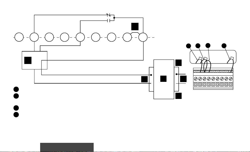
Figure 2 – Thermostat base
7
Y
HM2
6
RC
Page 10
WIRING DIAWIRING DIA
WIRING DIA
WIRING DIAWIRING DIA
GRAMSGRAMS
GRAMS
GRAMSGRAMS
All wiring diagrams are for typical systems only. Refer to equipment manufacturers' instructions for specific system wiring
information.
H
HM1 HM2
6
Y
G
W
E
1
From heating system
2
From 24 VAC transformer
3
Red jumper wire (provided)
For humidifier wiring see pages 14-15.
See page 9 for letter identification.
Figure 3 – Typical wiring diagram for heating only, single transformer system
RC RH
1
3
2
RH
W
HM1 W RH RC G Y HM2 6
L
J
I
K
M
NOTE: Ensure that RED RH/RC jumper wire (provided with
thermostat) is connected between thermostat's RH and RC
terminals for proper operation with this system.
8
Page 11

LETTER IDENTIFICATION FOR WIRING DIAGRAMS
Humidifier System
A
Zone Valve
B
Cooling System
C
Fan Relay
D
Heating System
E
Installation/Configuration
Jumper Wire
H
TRANSFORMER
I
24 VAC Side
J
120 VAC Side
K
Hot Side
L
Neutral Side
M
HEATING TRANSFORMER
N
COOLING TRANSFORMER
O
Jumper Wire (field-installed)
P
9
Page 12
H
HM1 HM2
1
2
3
4
5
6
Y
G
C
From heating system
From 24 VAC transformer
Red jumper wire (provided)
From fan relay
From cool system
W
ED
For humidifier wiring see pages 14-15.
See page 9 for letter identification.
Figure 4 – Typical wiring diagram for heat only, cool only, & heat/cool single transformer system
RC RH
3
2
1
Y
G
R
W
L
J
I
K
H
HM1 W RH RC G Y HM2 6
M
NOTE: Ensure that RED RH/RC jumper wire (provided with
thermostat) is connected between thermostat's RH and RC
terminals for proper operation with this system.
NOTE: For three-wire heat only system, connect terminals
RHRH
and
RH. For cool only system, connect terminals
RHRH
10
YY
,,
G G
Y
,
G and
YY
,,
G G
4
GG
G
GG
RHRH
RH.
RHRH
5
,,
WW
,
W
,,
WW
Page 13
H
HM1 HM2
1
2
6
B
Y
614
5
2
G
From heating system
From 24 VAC transformer
W
(through zone valve)
3
Red jumper wire (provided)
4
From zone valve system
For humidifier wiring see pages 14-15.
See page 9 for letter identification.
Figure 5 – Typical wiring diagram for heat only, three-wire, zone valve system
Installation/Configuration
RC
RH
3
2
1
R
W
H
L
J
I
HM1 W RH RC G Y HM2 6
K
M
NOTE: Thermostat must have batteries installed.
NOTE: Ensure that RED RH/RC jumper wire (provided with
thermostat) is connected between thermostat's RH and RC
terminals for proper operation with this system.
11
4
6
Page 14

HM1 HM2
6
G
Y
W
RC RH
C
1
From heating system
2
From 24 VAC heating transformer
3
From 24 VAC cooling transformer
4
From fan relay
5
From cooling system
For humidifier wiring see pages 14-15.
See page 9 for letter identification.
2
1
L
ED
J
I
K
HM1 W RH RC G Y HM2 6
3
Y
G
W
R
H
RC
M
L
J
O
K
M
Figure 6 – Typical wiring diagram for heat/cool, two-transformer system
12
5
4
Page 15
HM1 HM2
6
G
Y
C
W
D
RC
RH
2
3
1
L
J
I
HM1 W RH RC G Y HM2 6
K
Y
G
C
R
1
From 24 VAC cooling transformer
2
From fan relay
3
From cooling system
For humidifier wiring see pages 14-15.
See page 9 for letter identification.
Figure 7 – Typical wiring diagram for three-wire cooling system
Installation/Configuration
M
13
Page 16
1
1
HM1
6 Y G W
HM2
RC RH
A
NOTE: Two terminal choices (HM1 or HM2) are provided for
humidifier control. When the humidity setting is higher than the
room humidity:
HM1 turns off the humidifier when the call for heat ends.
HM2 powers the humidifier an additional 30 seconds after the
call for heat ends to provide slightly more humidity output.
Most installers will use HM1 unless they feel more humidity is
desirable.
Figure 8 – Typical wiring diagram for 24V humidifier system
14
H
M
HM1 W RH RC G Y HM2 6
L
KJ
I
M
1
From humidity system
See page 9 for letter identification.
Page 17

1
1
HM1 6 Y G W
Relay
90-290Q
or equivalent
A
K
Figure 9 – Typical wiring diagram for 120V humidifier system
Installation/Configuration
HM2
RC RH
J
15
HM
HM1 W RH RC G Y HM2 6
L
K
I
M
1
From humidity system
See page 9 for letter identification.
Page 18

CONFIGURACONFIGURA
CONFIGURA
CONFIGURACONFIGURA
JUMPERSJUMPERS
JUMPERS
JUMPERSJUMPERS
Before turning power on to the system,
the jumpers on the back of the
thermostat must be configured to
operate correctly with the system
equipment.
This thermostat is configured from the
factory to operate a standard fossil fuel
(gas, oil, etc.), forced hot air system
with a single stage air conditioning
compressor and fan. This is the correct
configuration for any system that
DOES NOT require the thermostat to
energize the fan on a call for heat.
TIONTION
TION
TIONTION
If you have an electric heat or other
system that REQUIRES the thermostat
to control the fan, find and cut the
jumper lead labelled W914 (see fig.
10). This will allow the thermostat to
energize the fan instantly on a call for
heat. If you are unsure if the system
requires the thermostat to control the
fan, contact a qualified heating and air
conditioning service person.
16
A remote sensor can be used with this
thermostat. To use a remote sensor,
jumper W922 must be clipped (see fig.
10) and the REMT SEN option in the
configuration menu must be set to ON.
Page 19

Clip for remote sense
1
3-pin connector
2
Clip for electric heat
3
Installation/Configuration
1 32
W914
W922
Figure 10 – Jumper locations
17
Page 20

CONFIGURACONFIGURA
CONFIGURA
CONFIGURACONFIGURA
TION MENUTION MENU
TION MENU
TION MENUTION MENU
The configuration menu allows you to set thermostat operating characteristics to your system or personal requirements.
To enter the menu, press TIME
menu options. Press
arrow keys to change options. Either the installer or the operator may change shaded
and TIME
FWD
once at the same time. Press TIME
BACK
to advance through the
FWD
options. We recommend that other options be set by the installer.
Step Press Button(s) Displayed (Factory Default) Press or to select: COMMENTS
1 EMR
TIME
TIME
2 SET CYCL HEAT
TIME
3 SET CYCL COOL
TIME
4 COOL FAN DELA OFF
TIME
5 COOL FAN DELA ON
TIME
6 COMP LOCK
TIME
7 SYSTEM
TIME
FWD
BACK
FWD
FWD
FWD
FWD
FWD
FWD
(ON)
(05)
(12)
(01)
(04)
(OFF)
(HEAT-OFF-COOL-AUTO)
OFF
02 - 40
09 - 40
01 - 127
01 - 05
ON
HEAT-OFF,
COOL-OFF,
HEAT-OFF-COOL
18
Selects EMR option ON or OFF
See page 32
Adjusts heat anticipation value (2 through 40)
See page 20
Adjusts cool anticipation value (9 through 40)
See page 20
Adjusts cool fan-off delay (1 through 127 sec.)
See page 20
Adjusts cool fan-on delay (1 through 5 sec.)
See page 20
Selects compressor lockout ON or OFF (see NOTE)
See page 21
Selects system switch choices for heat only,
cool only, heat/cool or automatic changeover
See page 21
Page 21

CONFIGURACONFIGURA
CONFIGURA
CONFIGURACONFIGURA
TION MENU (cont’TION MENU (cont’
TION MENU (cont’
TION MENU (cont’TION MENU (cont’
d)d)
d)
d)d)
8 0˚F
TIME
9 (˚F) ˚C
TIME
10 BEEP
TIME
11 REMT SEN
TIME
12
TIME
13
TIME
14
TIME
15
TIME
16
PROGRAM
FWD
FWD
FWD
FWD
FWD
FWD
FWD
FWD
(0)
(ON)
(OFF)
PART LOCK
(OFF)
LOCK
(OFF)
RH
DRY
(0)
RUN
5 LO to
20 LO to
HI - LO
5 HI
OFF
ON
ON
ON
20 HI
Adjusts temperature display higher or lower
See page 32
Adjusts temperature display to ˚F or ˚C.
Turns beeper ON or OFF
Selects remote sensor OFF or ON
See page 21
Selects partial keypad lockout OFF or ON
See page 34
Selects total keypad lockout OFF or ON
See page 34
Adjusts humidity display higher or lower
See page 36
Selects programmable automatic humidity reduction
See page 37
Returns to normal operation
NOTE: COMP LOCK OFF permanently defeats the compressor lockout. Turn this feature off only if the system already
provides for compressor short-cycle protection.
19
Page 22

CONFIGURACONFIGURA
CONFIGURA
CONFIGURACONFIGURA
ADJUSTABLE ANTICIPATIONADJUSTABLE ANTICIPATION
ADJUSTABLE ANTICIPATION
ADJUSTABLE ANTICIPATIONADJUSTABLE ANTICIPATION
This option allows the cycle times in
heating and cooling to be increased or
decreased. The factory set values can
be adjusted higher for longer cycles or
lower for shorter cycles.
The adjustment range for HEATING is
from 2 to 40. The factory preset is 5.
The adjustment range for COOLING
is from 9 to 40. The factory preset is
Anticipation Value Cycle Length Differential Temperature Cycle Length Differential Temperature
These numbers are approximate and represent operation with a typical system. Actual temperature differentials and run
times may vary widely based on your building and equipment, as well as outdoor temperature conditions.
TIONTION
TION
TIONTION
12. The recommended initial setting
for hydronic (hot water or steam)
systems is 35.
The cooling will not go below 9
because compressors require a longer
cycle.
The chart below shows how this
adjustment range affects thermostat
performance.
HEATING COOLING
Shorter 0.4–0.6˚F (0.2–0.3˚C) N/A2–8 N/A
Longer Shorter9–20 0.6–1.0˚F (0.3–0.6˚C) 0.6–1.0˚F (0.3–0.6˚C)
Hydronic Longer21–40 1.0–1.6˚F (0.6–0.9˚C) 1.0–1.6˚F (0.6–0.9˚C)
20
COOL FAN-ONCOOL FAN-ON
COOL FAN-ON
COOL FAN-ONCOOL FAN-ON
AND FAN-OFF DELAYAND FAN-OFF DELAY
AND FAN-OFF DELAY
AND FAN-OFF DELAYAND FAN-OFF DELAY
This option allows a selection of a fanon delay of 1 to 5 seconds on a call for
cool and 1 to 127 seconds of fan-off
delay after the thermostat has satisfied
the call for cool.
A short delay to allow the A-coil to
cool off before the fan turns on may be
preferred. This also allows the
Page 23
compressor and the fan to come on at
slightly different times, which allows
full power to the compressor on start
up.
The fan off delay allows the fan to
continue running after the compressor
has shut off. This distributes the
cooling that would otherwise stay
trapped in the air conditioning coils
through the ducts. Ideally the timing
would be set so the fan shuts off just as
the cool air is exhausted. If this timing
is set too long the fan may begin
blowing warm air before it shuts off.
Shortening the fan-off delay will
prevent this.
COMPRESSOR LOCKOUTCOMPRESSOR LOCKOUT
COMPRESSOR LOCKOUT
COMPRESSOR LOCKOUTCOMPRESSOR LOCKOUT
This thermostat is designed with an
optional compressor lockout feature.
It is designed to protect the system
against premature compressor failure
Installation/Configuration
by “locking out” the compressor for at
least five minutes after each cycle.
When the thermostat is in compressor
lockout, the word COOL will flash on
the display. During this period, the
compressor will not be energized.
Selecting COMP LOCK ON in the
configuration menu (page 18, step 6)
will enable this feature.
DISABLING HEAT, COOL,DISABLING HEAT, COOL,
DISABLING HEAT, COOL,
DISABLING HEAT, COOL,DISABLING HEAT, COOL,
OR AUTO MODESOR AUTO MODES
OR AUTO MODES
OR AUTO MODESOR AUTO MODES
The automatic changeover feature of
this thermostat can be disabled
(automatic changeover allows the
thermostat to switch between heating
and cooling to maintain temperature).
If this thermostat is controlling a
heating-only or cooling-only system,
the heat, cool, or auto modes can be
disabled.
21
CONFIGURACONFIGURA
CONFIGURA
CONFIGURACONFIGURA
TIONTION
TION
TIONTION
Lockout Bypass Option
FOR QUALIFIED SERVICE
TECHNICIANS’ USE ONLY.
HOMEOWNERS SHOULD
NOT USE THIS FEATURE
DUE TO POSSIBILITY OF
EQUIPMENT OR PROPERTY
DAMAGE, OR PERSONAL
INJURY.
To override this feature for one
cycle while testing thermostat
operation, press SET
DAY
SET
time.
OPTIONAL REMOTEOPTIONAL REMOTE
OPTIONAL REMOTE
OPTIONAL REMOTEOPTIONAL REMOTE
TEMPERATURE SENSETEMPERATURE SENSE
TEMPERATURE SENSE
TEMPERATURE SENSETEMPERATURE SENSE
An optional remote sensor (part #
F145-1328) can be attached to this
thermostat and may be wired as far
buttons at the same
TIME
and
Page 24

CHECK CHECK
CHECK
CHECK CHECK
away as 300 feet. The thermostat will
use the temperature in the remote
location as its room temperature
display.
This is an excellent feature if the
thermostat is in a poor location for
sensing temperature or the thermostat
is in a separate room to prevent
tampering.
THERMOSTTHERMOST
THERMOST
THERMOSTTHERMOST
AA
T OPERAT OPERA
A
T OPERA
AA
T OPERAT OPERA
NOTE
The remote sense feature will not
work if the system does not provide
24V to the thermostat (example:
heating-only system or 3-wire zone
valves).
To use a remote sensor, jumper W922
must be clipped (see figure 10) and
the REMT SEN option in the configuration menu (on page 19) must be set
to ON.
TIONTION
TION
TIONTION
After the thermostat is installed and
configured, do the following to ensure
proper operation.
FAN OPERATIONFAN OPERATION
FAN OPERATION
FAN OPERATIONFAN OPERATION
If your system does not have a G
terminal connection, skip to “Heating
System” section.
1. Turn power on to the system.
2. Press
displayed. The fan should begin to
operate.
3. Press
displayed. The fan should stop
operating.
HEATING SYSTEMHEATING SYSTEM
HEATING SYSTEM
HEATING SYSTEMHEATING SYSTEM
1. Press
displayed. If the heating system has
a standing pilot, ensure that it is lit.
2. Press
FAN
FAN
SYSTEM
FF
AN ONAN ON
until
F
AN ON is
FF
AN ONAN ON
FF
AN AN
AA
F
AN
FF
AN AN
HEAHEA
HEA
HEAHEA
A
AA
TT
T is
TT
UTUT
UT
UTUT
until
until
to adjust thermostat
22
OO
O is
OO
setting above room temperature.
The heating system should begin to
operate.
3. Press
below room temperature. The
heating system should stop
operating.
HUMIDIFIER OPERATION CHECKHUMIDIFIER OPERATION CHECK
HUMIDIFIER OPERATION CHECK
HUMIDIFIER OPERATION CHECKHUMIDIFIER OPERATION CHECK
NOTE: Humidifier will only operate
when the furnace is running.
1. Press
displayed.
2. Press until the setpoint is
above the room temperature by a
few degrees and the furnace starts
running.
3. Press
will show the current humidity
level in the room and the current
humidity setpoint for approximately 10 seconds.
4. To check humidifier, press
to adjust temperature
SYSTEM
switch until
HUMIDITY %
. The display
HEAHEA
HEA
HEAHEA
TT
T is
TT
to
Page 25

HUMIDIFIER OPERATIONHUMIDIFIER OPERATION
HUMIDIFIER OPERATION
HUMIDIFIER OPERATIONHUMIDIFIER OPERATION
CHECK (cont’d.)CHECK (cont’d.)
CHECK (cont’d.)
CHECK (cont’d.)CHECK (cont’d.)
raise the humidity setpoint (45%
maximum) above the room humidity level. The humidifier should
operate. If the humidity in the room
is above 45%, press
the setting to 45% (the maximum
setting) and hold the up arrow in
for 5 seconds. The display will read
ON and the humidifier will operate.
This test will last for one heat cycle.
The humidifier will then operate
when the heat is running to
maintain your humidity setting.
COOLING SYSTEMCOOLING SYSTEM
COOLING SYSTEM
COOLING SYSTEMCOOLING SYSTEM
WARNING
!
To prevent compressor and/or
property damage, if the outdoor
temperature is below 50°F
(10°C), DO NOT operate the
cooling system.
to adjust
Installation/Configuration
CHECK CHECK
CHECK
CHECK CHECK
1. Press
2. Press to adjust thermostat
3. Press
RESETTING THERMOSTATRESETTING THERMOSTAT
RESETTING THERMOSTAT
RESETTING THERMOSTATRESETTING THERMOSTAT
The thermostat can be reset back to
factory default programs and configuration options. Removing power from
the thermostat will not reset it to the
default settings. Before resetting the
SYSTEM
until COOL is
displayed.
setting below room temperature.
The fan should come on (after the
fan-on delay time, if any), followed
by cold air circulation. There may
be a 5 minute delay on compressor
operation.
to adjust temperature
setting above room temperature.
The cooling system should stop
operating, and the fan should stop
running (after the fan-off delay
time, if any).
23
THERMOSTTHERMOST
THERMOST
THERMOSTTHERMOST
AA
T OPERAT OPERA
A
T OPERA
AA
T OPERAT OPERA
thermostat, you may want to make
note of the previously selected
configuration options and programming.
To reset the thermostat, press and
release PROGRAM
FAN
the
buttons at the same time. This will
reset the thermostat to factory default
programs and configuration. The
display will momentarily go blank,
then all segments on the display will
momentarily be shown. The thermostat
will then go into the
will maintain factory preset temperatures.
, TIME
TION (cont’TION (cont’
TION (cont’
TION (cont’TION (cont’
RUN
, then press
BACK
and
HOLDHOLD
HOLD mode and
HOLDHOLD
d.)d.)
d.)
d.)d.)
Page 26

PROGRAMMING
MANUMANU
AL OPERAAL OPERA
MANU
AL OPERA
MANUMANU
AL OPERAAL OPERA
(Bypassing the Pr(Bypassing the Pr
(Bypassing the Pr
(Bypassing the Pr(Bypassing the Pr
Your Comfort-Set 90 thermostat can
be used to control temperature
manually (without programming).
For manual operation, press
to select
HEAHEA
HEA
HEAHEA
PROGRAM
to set the temperature as
desired.
PRPR
OGRAMMED OPERAOGRAMMED OPERA
PR
OGRAMMED OPERA
PRPR
OGRAMMED OPERAOGRAMMED OPERA
Planning Planning
Planning
Planning Planning
YY
Y
YY
The sample schedule (pages 26 & 27)
shows the factory installed programs
for heating and cooling. The heating
and cooling programs are separate, and
must be programmed individually. To
use the factory program, set the clock
and press PROGRAM
thermostat
TIONTION
TION
TIONTION
oo
o
oo
TT
COOLCOOL
T or
COOL, then press
TT
COOLCOOL
HOLD
. Use or
our Prour Pr
oo
our Pr
our Prour Pr
SYSTEM
gg
o
g
oo
gg
set to
gg
g
gg
rr
r
rr
rr
am)am)
r
am)
rr
am)am)
amam
am
amam
RUN
HeaHea
Hea
HeaHea
SYSTEM
TIONTION
TION
TIONTION
with the
tt
t,
tt
CoolCool
Cool, or
CoolCool
AA
A
AA
utouto
uto.
utouto
Fill out the blank schedules (pages 28
& 29) with the time and temperatures
you want in your program. Fill in
every space for your program.
The same temperature can be repeated
more than once if you do not want the
temperature to change over several
time periods. This is useful for homes
or businesses that are occupied all day
and only want a setback temperature at
night.
Entering Entering
Entering
Entering Entering
TT
o Set the Cloco Set the Cloc
T
o Set the Cloc
TT
o Set the Cloco Set the Cloc
1. Press PROGRAM
2. Press SET
show the hour. Use TIME
TIME
YY
our Prour Pr
oo
gg
rr
Y
our Pr
YY
our Prour Pr
BACK
to set to the current hour
amam
o
g
r
am
oo
gg
rr
amam
kk
k:
kk
RUN
TIME
. The display will
.
FWD
or
and AM/PM designation.
24
TIME
3. Press SET
again. The
display will show minutes. Use TIME
FWD
or TIME
BACK
to set to the
current minutes.
4. Press PROGRAM
TT
o Set the Dao Set the Da
T
o Set the Da
TT
o Set the Dao Set the Da
5. Press SET
yy
y:
yy
DAY
RUN
.
. The display will
indicate a day of the week. Use TIME
FWD
or TIME
BACK
to set to the
current day of the week.
gg
rr
amam
g
r
am:
gg
rr
amam
to select
COOLCOOL
COOL (for
COOLCOOL
RUN
.
HEAHEA
HEA
HEAHEA
TT
T (for
TT
6. Press PROGRAM
TT
o Set the Pro Set the Pr
T
o Set the Pr
TT
o Set the Pro Set the Pr
7. Press
SYSTEM
oo
o
oo
heating program) or
cooling program).
VIEW
8. Press PROGRAM
The display will show
one time.
MORMOR
MOR and the
MORMOR
settings for time and temperature.
Page 27

9. If you program Monday the first
time you press PROGRAM
VIEW
it
will be copied to the rest of the week.
To program the other days of the week
ADV.
press
/DA Y until you reach the
day you wish to change and follow
Steps 10, 11 & 12. You can also copy
the program from one day to another.
T o copy, press
HOLD
/COPY. The
display will show COPY, and all the
other days of week will be flashing.
HOLD
Press
/COPY again to copy the
day in to the rest of the week or press
TIME
FWD
or TIME
BACK
until
you reach the day you want to copy to
and press
HOLD
/COPY.
10.Press TIME
FWD
or TIME
BACK
to set the time on the display as
selected in your HEATING or
COOLING Schedule. Be sure to
check the AM or PM on the display.
11.Press the red or blue
button to adjust the temperature to
match your schedule. If you want the
fan ON continuously during this
period, press
12.Press PROGRAM
FAN
.
VIEW
one time.
MOR on the display will change to
DA Y. Repeat steps 10 and 11 to enter
time and temperature for this period.
25
Programming
13.Press PROGRAM
VIEW
to
continue through the entire schedule,
entering time and temperature for each
period. When you are satisfied that
your program matches your schedule,
press PROGRAM
RUN
. Programming is now complete for this mode
and your program is running.
14.To program the other mode, repeat
the procedure from step 6.
Page 28

7 Day Sample HEAT Program Schedule
(Shows factory programming)
MON
TUE
WED
THU
FRI
SAT
SUN
1
Morning (MOR)
2
Day (DAY)
3
Evening (EVE)
4
Night (NHT)
5
Start Time
6
Temperature
6:00 AM 70°F (21°C) 8:00 AM 70°F (21°C)
6:00 AM 70°F (21°C) 8:00 AM 70°F (21°C)
6:00 AM 70°F (21°C) 8:00 AM 70°F (21°C)
6:00 AM 70°F (21°C) 8:00 AM 70°F (21°C)
6:00 AM 70°F (21°C) 8:00 AM 70°F (21°C)
6:00 AM 70°F (21°C) 8:00 AM 70°F (21°C)
6:00 AM 70°F (21°C) 8:00 AM 70°F (21°C)
1
2 3 4
5 6 5 6 5 6 5 6
62°F (16°C)
62°F (16°C)
62°F (16°C)
62°F (16°C)
62°F (16°C)
62°F (16°C)
62°F (16°C)
26
5:00 PM 10:00 PM
5:00 PM
5:00 PM
5:00 PM
5:00 PM
5:00 PM
5:00 PM
10:00 PM
10:00 PM
10:00 PM
10:00 PM
10:00 PM
10:00 PM
62°F (16°C)
62°F (16°C)
62°F (16°C)
62°F (16°C)
62°F (16°C)
62°F (16°C)
62°F (16°C)
Page 29

7 Day Sample COOL Program Schedule
(Shows factory programming)
MON
TUE
WED
THU
FRI
SAT
SUN
1
Morning (MOR)
2
Day (DAY)
3
Evening (EVE)
4
Night (NHT)
5
Start Time
6
Temperature
6:00 AM 78°F (25°C) 8:00 AM 78°F (25°C)
6:00 AM 78°F (25°C) 8:00 AM 78°F (25°C)
6:00 AM 78°F (25°C) 8:00 AM 78°F (25°C)
6:00 AM 78°F (25°C) 8:00 AM 78°F (25°C)
6:00 AM 78°F (25°C) 8:00 AM 78°F (25°C)
6:00 AM 78°F (25°C) 8:00 AM 78°F (25°C)
6:00 AM 78°F (25°C) 8:00 AM 78°F (25°C)
1
2 3 4
5 6 5 6 5 6 5 6
85°F (29°C)
85°F (29°C)
85°F (29°C)
85°F (29°C)
85°F (29°C)
85°F (29°C)
85°F (29°C)
27
5:00 PM 10:00 PM
5:00 PM
5:00 PM
5:00 PM
5:00 PM
5:00 PM
5:00 PM
10:00 PM
10:00 PM
10:00 PM
10:00 PM
10:00 PM
10:00 PM
82°F (27°C)
82°F (27°C)
82°F (27°C)
82°F (27°C)
82°F (27°C)
82°F (27°C)
82°F (27°C)
Programming
Page 30

7 Day Personal HEAT
Program Schedule
MON
TUE
WED
THU
FRI
SAT
SUN
1
Morning (MOR)
2
Day (DAY)
3
Evening (EVE)
4
Night (NHT)
5
Start Time
6
Temperature
1
2 3 4
5 6 5 6 5 6 5 6
28
Page 31

7 Day Personal COOL
Program Schedule
MON
TUE
WED
THU
FRI
SAT
SUN
1
Morning (MOR)
2
Day (DAY)
3
Evening (EVE)
4
Night (NHT)
5
Start Time
6
Temperature
1
2 3 4
5 6 5 6 5 6 5 6
29
Programming
Page 32

FEATURES
Thermostat Features:
Pushbutton Backlight --------------- 31
Factory Preprogramming ----------- 31
Arm Chair Programming ----------- 31
Temporary Program Override------ 31
Indefinite Program Hold
(Bypassing the Program) -------- 31
Selectable Energy Management
Recovery (EMR) ----------------- 32
Automatic Heat/Cool
Changeover------------------------ 32
Adjustable T emperature Display -- 32
Programmable Fan Control -------- 33
Programmable Vacation
Time Temp ------------------------ 33
Daylight Savings Time Button ---- 33
Battery Back-up --------------------- 3 3
Keypad Lockout --------------------- 34
Thermostat Start-up after
Power Loss ------------------------ 34
Compressor Short Cycle
Protection -------------------------- 35
Air Filter Change-Out Indicator --- 35
System and Thermostat
Diagnosis -------------------------- 35
30
Humidistat Features:
Adjustable Humidity Display ------ 36
Humidifier Maintenance
Indicator ---------------------------36
Humidifier Control and
Monitoring ------------------------ 3 7
Programmable Automatic
Humidity Reduction ------------- 37
Page 33

PushbPushb
Pushb
PushbPushb
utton Bacutton Bac
utton Bac
utton Bacutton Bac
klightklight
klight
klightklight
The large numbers and letters on your
LCD screen make it easy to see. In low
light conditions, press the button on
top of the thermostat and the display
will light up for three seconds. For ten
minutes after pressing the light button,
pressing any other button will light the
display for ten seconds. The display
light uses power from the 3 “AA”
alkaline batteries installed. Excessive
use of the display light will reduce
battery life.
FF
actoractor
y Pry Pr
ee
prpr
oo
gg
rr
F
actor
FF
actoractor
y Pr
y Pry Pr
ammingamming
e
pr
o
g
r
amming
ee
prpr
oo
gg
rr
ammingamming
This thermostat has been programmed
at the factory. The chart in the
programming examples section lists
these factory settings. If the times and
temperatures are the same as your
schedule, you may simply run the
factory installed program by pressing
PROGRAM
RUN
.
ArAr
m Chair Prm Chair Pr
Ar
m Chair Pr
ArAr
m Chair Prm Chair Pr
oo
gg
rr
o
g
r
oo
gg
rr
ammingamming
amming
ammingamming
..
.
..
The thermostat uses 24 VAC power
supplied by the system for normal
operation. However, if the installed
“AA” batteries are providing sufficient
power, you can program the thermostat
away from the wall. If the thermostat
indicates low battery power (CHECK
BATTERY), refer to the Battery Backup feature (page 33).
TT
emporempor
arar
y Pry Pr
oo
gg
rr
am Ovam Ov
erer
rideride
T
empor
TT
emporempor
ar
arar
y Pr
y Pry Pr
o
g
oo
gg
r
am Ov
rr
am Ovam Ov
er
erer
ride
rideride
..
.
..
Any time your program is running and
you would like to override it for a
specific amount of time, press
or until the temperature you
want is displayed. The display will
indicate HOLD, and the number of
hours remaining in the hold period will
be indicated with the word HRS. To
adjust the length of time for the
override, press TIME
BACK
. HOLD TILL will be displayed
FWD
or TIME
as well as the HOLD period expiration
31
Features
time. Press TIME
BACK
buttons until you reach the time
FWD
or TIME
you would like it to resume the
program. The TIME
BACK
buttons adjust the time in 15
FWD
or TIME
minute increments. This programmed
hold time has a 19 hour maximum and
15 minute minimum. Beyond 19 hours
you may wish to use the vacation hold
feature (page 33). If you need to, you
can adjust the temperature up or down.
Indefinite PrIndefinite Pr
Indefinite Pr
Indefinite PrIndefinite Pr
oo
gg
rr
am Hold.am Hold.
o
g
r
am Hold.
oo
gg
rr
am Hold.am Hold.
If you want to operate the thermostat
to keep a set temperature without a
program running, press PROGRAM
HOLD
. The or buttons
can be used to raise or lower the
temperature. The thermostat will hold
the set temperature until you return to
the program by pressing PROGRAM
RUN
.
Page 34

SelectaSelecta
Selecta
SelectaSelecta
ManaMana
Mana
ManaMana
bb
le Enerle Ener
b
le Ener
bb
le Enerle Ener
gg
ement Rement R
g
ement R
gg
ement Rement R
gg
g
gg
ecoeco
eco
ecoeco
yy
y
yy
vv
v
vv
erer
y (EMR)y (EMR)
er
y (EMR)
erer
y (EMR)y (EMR)
EMR causes the thermostat to start
operating the system early in order to
make the building temperature reach
your program setpoint at the time you
specify. In heating, the thermostat will
start 5 minutes early for every 1°F
difference between the room temperature and the next programmed
temperature. In cooling, the thermostat
uses 15 minutes per °F.
EXAMPLE: If the temperature in the
room is 65°F and the thermostat is
programmed for 70°F at 7 AM, the
thermostat will start approximately 25
minutes early. The difference between
the room temperature (65°F) and the
setpoint (70°F) is 5°. 5° X 5 minutes
per °F = 25 minutes. The setpoint on
the display will actually change to
display 70° about 25 minutes early.
The maximum time the thermostat can
start early in heating is 75 minutes.
The maximum time the thermostat can
start early in cooling is 3 hours and 45
minutes. Cooling can start earlier
because it takes longer for cooling
systems to reach the desired temperature.
To select or deselect this feature, refer
to the CONFIGURATION section
(page 18, step 1).
AA
utomautoma
tic Heatic Hea
A
utoma
AA
utomautoma
tic Hea
tic Heatic Hea
t/Cool Changt/Cool Chang
t/Cool Chang
t/Cool Changt/Cool Chang
eoeo
eo
eoeo
vv
erer
v
er
vv
erer
If you have a heating/cooling system,
the thermostat can be set to automatically switch the system from heating to
cooling as needed. To set your
thermostat to this operating mode,
press
button until AUTO is
SYSTEM
displayed on the screen.
Pressing the and buttons
at the same time will change the
setpoint temperature displayed to the
32
setpoint of the other mode. This will
allow you to modify both the HEAT
and COOL setpoints to accommodate a
HOLD condition while in Automatic
Changeover mode. To adjust, refer to
the Configuration section (page18,
step 7).
AdjustaAdjusta
Adjusta
AdjustaAdjusta
bb
le le
TT
emperemper
aa
turtur
b
le
T
emper
bb
le le
TT
emperemper
a
tur
aa
turtur
e Displae Displa
e Displa
e Displae Displa
yy
y
yy
The room temperature display can be
adjusted to read higher or lower by
following the configuration menu and
adjusting the temperature to a higher
or lower value. The thermostat is
calibrated at the factory to display a
very accurate room temperature, but
due to various conditions and/or
personal preference, you may wish to
adjust the thermostat display higher or
lower (up to 5°F). For example, if the
thermostat displays a room temperature of 70° but you want it to display
73°, you can adjust it. To adjust, refer
to the CONFIGURATION section
(page 19, step 8).
Page 35

PrPr
oo
gg
rr
ammaamma
bb
le Fle F
Pr
PrPr
o
oo
g
r
amma
gg
rr
ammaamma
b
bb
le F
le Fle F
an Contran Contr
an Contr
an Contran Contr
olol
ol
olol
This feature allows you to have your
fan operate continuously through one
or more programmed time periods.
This is useful if you want constant air
circulation in your location during a
specific time period. If you do not use
this feature, the fan will cycle normally
with the heating and cooling system.
PrPr
oo
gg
rr
ammaamma
bb
le le
VV
acaaca
tion tion
Pr
o
PrPr
oo
TT
emperemper
T
emper
TT
emperemper
g
r
amma
gg
rr
ammaamma
aa
a
aa
turtur
tur
turtur
b
le
V
bb
le le
VV
e Opere Oper
e Oper
e Opere Oper
aca
acaaca
aa
tion.tion.
a
tion.
aa
tion.tion.
tion
tion tion
Time/Time/
Time/
Time/Time/
The VACATION mode allows you to
program the thermostat to hold a
constant temperature for 1 to 29 days.
At the end of the day and time you
select, the thermostat will return to
normal program operation.
To program the number of days, press
HOLD then press SET
DAY
. VACA
HOLD TILL will be displayed. The
display will also show DA YS
(flashing) and the number 5. To
change the number of vacation days,
press TIME
Press
FWD
or TIME
or to set the
BACK
.
temperature you wish to maintain
while away. While still in the vacation
mode, set the time you want the
program to resume by pressing SET
TIME
once. The current time will
display. Press TIME
FWD
to adjust
the time in 15 minute increments. You
may wish to select a few hours in
advance of your expected return to
allow time to reach the desired
temperature. Your thermostat is now
programmed to hold the temperature
you selected through your vacation for
HEAT, COOL, or AUTO.
After 20 seconds the display will
return to time/temperature alternation,
and will display VACA. Pressing SET
again will activate the vacation
DAY
mode settings. Pressing PROGRAM
RUN
cancels this feature and begins
33
Features
running your normal program.
DaDa
ylight Saylight Sa
Da
ylight Sa
DaDa
ylight Saylight Sa
vings vings
vings
vings vings
Time Button.Time Button.
Time Button.
Time Button.Time Button.
One button adjustment allows you to
change your thermostat clock between
Standard Time and Daylight Savings
time. Simply push the DAYLIGHT
SAVINGS TIME button to advance
the time forward one hour in the
Spring. In the Fall, press the DAY-
LIGHT SAVINGS TIME button
twice to fall back an hour. If you push
it three times in a row (in less than 30
seconds) it will return to the original
time setting. After clock adjustment,
press PROGRAM
RUN
to resume
your normal program.
BaBa
ttertter
y Bacy Bac
k-Upk-Up
Ba
BaBa
tter
ttertter
y Bac
y Bacy Bac
k-Up
k-Upk-Up
..
.
..
Three “AA” alkaline batteries allow
the thermostat to maintain its program
in the event of a power loss. They also
operate the back light for viewing the
Page 36

display in low light conditions, and
allow for armchair programming.
CHECK BATTERY will be displayed
when the batteries are low. To assure
optimum performance, change
batteries once a year or when CHECK
BATTERY is displayed. When
changing batteries, always replace all
three batteries with new “AA” alkaline
batteries (for optimum performance,
we recommend Energizer
®
batteries).
If the batteries must be changed
frequently, it may indicate a problem
with the system. Contact the heating/
cooling system manufacturer or a
service person. Remember that
excessive use of the display light will
reduce battery life.
KK
ee
ypad Locypad Loc
K
e
ypad Loc
KK
ee
ypad Locypad Loc
kk
out.out.
k
out.
kk
out.out.
This security feature allows you to
lock out the keypad to prevent
unauthorized tampering with the
program. Two levels of security are
available, Total Keypad Lockout or
Partial Keypad Lockout. Total Keypad
Lockout renders all buttons inoperative. Partial Keypad Lockout allows
only the
or to operate for
temporary temperature overrides. It
also limits the temperature to the
maximum heating and minimum
cooling temperatures used in your
program. This is especially useful in
buildings where unscheduled events
are common. Anyone can change the
temperature, but only between the
temperatures you set and only for two
hours or the number of hours you
specify if you set up your Hold Till
timing (see Temporary Program
Override, page 31). To select or
deselect this feature, refer to the
CONFIGURATION section (page 19,
steps 12 and 13).
34
TT
herher
mostamosta
t Start Star
T
her
TT
herher
After After
After
After After
mosta
mostamosta
TT
otal Potal P
T
otal P
TT
otal Potal P
t Star
t Start Star
oo
ww
o
w
oo
ww
tuptup
tup
tuptup
er Losser Loss
er Loss
er Losser Loss
..
.
..
On installation, or when power is
restored after a total power loss to the
thermostat, your thermostat will
automatically maintain a heating
temperature of 62°F (16°C) and a
cooling temperature of 85°F (29°C). A
total loss of power will occur when
you lose 24 VAC power to the
thermostat, and you have no battery
backup. If this happens, the thermostat
display will go blank in about one
minute after power loss.
When power is restored, the thermostat
will automatically return to the
temperatures listed above. If this
happens, set the clock and day of the
week (use steps 1 through 6 from
“Entering Y our Program”, page 24),
then select HEAT, COOL or AUTO
using the
PROGRAM
SYSTEM
. button, and press
RUN
to resume operation
with your previously set program.
Page 37

CompressorCompressor
Compressor
CompressorCompressor
ShorShor
t-Cyt-Cy
cc
le Prle Pr
Shor
ShorShor
t-Cy
t-Cyt-Cy
c
le Pr
cc
le Prle Pr
otection.otection.
otection.
otection.otection.
Your thermostat can be configured to
protect your system against premature
compressor failure by “locking out”
the compressor. This ensures that the
compressor will stay off for at least
five minutes on each cycle. When the
thermostat is in compressor lock-out,
the word COOL will flash. During this
period, the compressor will not be
energized. See installation and
configuration, page 18, step 6.
Air FilterAir Filter
Air Filter
Air FilterAir Filter
ChangChang
Chang
ChangChang
e-Out Indicae-Out Indica
e-Out Indica
e-Out Indicae-Out Indica
tortor
tor
tortor
..
.
..
This feature allows the thermostat to
display the words CHNG FLTR
(change filter) after a set time of fan
operation. This is a reminder to change
or clean your air filter. The factory set
interval for CHNG FLTR to be
displayed is 200 hours of fan operation. This can be set anywhere from 0
to 1950 hours in 25 hour increments. A
selection of 00 will cancel this
feature.
When CHNG FLTR is displayed, you
can clear it by pressing the HUM/
FLTR SERVICE button. This resets
the timer and starts counting the hours
until the next filter change.
The following steps will allow you to
change the number of hours for filter
change-out.
1. If you see CHNG FLTR on the
display, press the HUM/FLTR
SERVICE button once to reset the
timer. If you do not see CHNG FLTR
proceed to step 2.
On a 7–Day thermostat, when the
HUM/FLTR SERVICE button is
pressed twice, the display will show
the number of hours remaining before
CHNG FLTR indicator will display.
35
Features
2. Press the HUM/FLTR SERVICE
button. The display will show SET
FIL TER TIME and will show the
number of hours to filter change.
3. Press TIME
FWD
or TIME
BACK
to change the time to your requirements.
4. Press PROGRAM
RUN
to return
to the normal operating mode.
NOTE: If unsure what interval to use
between filter changes or cleaning,
contact the manufacturer of your
heating/cooling equipment.
System andSystem and
System and
System andSystem and
TT
herher
mostamosta
t Diat Dia
T
TT
her
herher
mosta
mostamosta
t Dia
t Diat Dia
gnosticsgnostics
gnostics
gnosticsgnostics
..
.
..
The display will indicate CHECK
SYSTEM if the room temperature
does not rise within two hours of the
call for heat. After two hours the
thermostat will quit calling for heat for
one minute (this allows some furnaces
to reset) and call for heat again. It will
Page 38

repeat this sequence three times. If the
temperature still does not rise, it will
continue to call for heat. This normally
indicates the heating system is not
working correctly. You may wish to
consult your furnace manufacturer or
service person.
The display will indicate CHECK STAT
if one of the following occurs.
• One of the buttons is stuck down or
in. Check buttons, make sure nothing
is pushing them in.
• The thermostat sensor is not
functioning. If using a remote sensor,
check connections, wiring and power.
• The humidity sensor is not functioning.
After checking the above, press
PROGRAM
RUN
to reset the
display. If this does not clear the
display, disconnect power and remove
the batteries for five minutes.
If these checks fail to solve the
problem, the thermostat should be
replaced.
AdjustaAdjusta
Adjusta
AdjustaAdjusta
bb
le Humidity Displale Humidity Displa
b
le Humidity Displa
bb
le Humidity Displale Humidity Displa
yy
..
y
.
yy
..
The room humidity display can be
adjusted to read higher or lower by
following the configuration menu and
adjusting the humidity to a higher or
lower value (up to 20% RH). The
sensed humidity is calibrated at the
factory. If you want to adjust it, refer
to the CONFIGURATION section
(page 19, step 14).
HumidifierHumidifier
Humidifier
HumidifierHumidifier
Maintenance IndicaMaintenance Indica
Maintenance Indica
Maintenance IndicaMaintenance Indica
tortor
tor
tortor
..
.
..
This feature allows the thermostat to
display the words CHCK HUMD
(check humidifier) after a set time of
humidifier operation. This is a
reminder to maintain or clean your
humidifier. The factory set interval for
CHCK HUMD to be displayed is 100
hours of humidifier operation. This can
36
be set anywhere from 0 to 1975 hours
in 25 hour increments. A selection of
00 will cancel this feature.
When CHCK HUMD is displayed,
you can clear it by pressing HUM/
FLTR SERVICE button. This resets
the timer and starts counting the hours
until the next humidifier maintenance.
The following steps will allow you to
change the number of hours for
humidifier maintenance.
1. If you see CHCK HUMD on the
display, press the HUM/FLTR
SERVICE button once to reset the
timer. Also display will show SET
HUMD TIME and will show the
number of hours to humidifier
maintenance.
2. Press TIME
FWD
or TIME
BACK
to change the time to your requirements.
3. Press PROGRAM
RUN
to return
to the normal operating mode.
Page 39

Humidifier ControlHumidifier Control
Humidifier Control
Humidifier ControlHumidifier Control
and Monitoringand Monitoring
and Monitoring
and Monitoringand Monitoring
When humidity key is pressed in the
run mode the actual humidity will be
displayed on the left side of the
display. HUMD is displayed above the
actual humidity. The humidity set
point is displayed on the right side of
the display.
or key may be pressed to
modify the humidity set point.
Maximum displayed humidity is 80%
RH and minimum displayed humidity
is 10% RH. If the heating system is
operating and there is a demand for
humidity, then the humidifier will
operate.
If the demand for humidity is not
satisfied for ten consecutive heat cycle
operations, the display will show the
word HUMD for one second and the
word MX for one second signaling
maximum possible humidity is reached
with respect to the humidifier’s
capability.
PrPr
oo
gg
rr
ammaamma
bb
le le
AA
utomautoma
Pr
o
g
r
amma
b
le
PrPr
oo
gg
rr
ammaamma
Humidity RHumidity R
Humidity R
Humidity RHumidity R
This feature automatically lowers
humidity when the outside temperature
drops. This is to prevent the interior
windows/walls from reaching the dew
point where water condenses on
surfaces. To achieve automatic
humidity reduction, the thermostat
lowers the humidity when furnace
cycles are long. When the furnace runs
shorter cycles, it increases humidity.
For suggested settings see table below.
HI Poorly insulated homes or homes with a lot of condensation on
windows/walls
0 Factory default – no humidity reduction
LO Well insulated homes requiring little humidity reduction
A
bb
le le
AA
eduction.eduction.
eduction.
eduction.eduction.
37
utoma
utomautoma
tictic
tic
tictic
If your window insulation is poor, you
need high humidity reduction. If your
window insulation is good, you need
low humidity reduction (factory
setting).
To adjust this feature, refer to the
CONFIGURATION section (page 19,
step 15). Selection of 0 will cancel this
feature.
Features
Page 40

FAQs 1F97-391
1. My thermostat is reading
in Celsius. How do I change
it to Fahrenheit?
Press PROGRAM
press TIME
Press TIME
press PROGRAM
RR
UNUN
R
UN to make certain the thermostat is in the run program mode, then
RR
UNUN
FWDFWD
FWD and TIME
FWDFWD
FWDFWD
FWD until you get to °C then press the
FWDFWD
RR
UNUN
R
UN to return to normal operation.
RR
UNUN
BB
AA
CKCK
B
A
CK at the same time to enter the configuration menu.
BB
AA
CKCK
UP UP
UP or
UP UP
DODO
WN WN
DO
WN arrow to select °F,
DODO
WN WN
2. The display shows the
CHECK BCHECK B
word
CHECK B
CHECK BCHECK B
What does it mean?
3. How do I bypass (not use)
the program?
4. What functions do the
connecting terminals have on
the subbase?
AA
TTERTTER
A
TTER
AA
TTERTTER
YY
Y.
YY
CHECK BCHECK B
CHECK B
CHECK BCHECK B
(not blinking) indicates a loss of power (24 volts) from the heating and cooling equipment
to the thermostat, or that the thermostat is operating on battery power only.
To bypass the program and operate the thermostat manually press the MODE
button to select Heat or Cool (whichever you prefer) and press
or Temp
ture setting you choose will be held until you manually change it using the Temp
Temp
temperature and maintain whatever temperature you set. If you decide to return to the
program, press PROGRAM
Typical terminals and functions:
HM1=Humidifier System 6=Zone V alv e Y=Cooling System
G=Fan Relay W=Heating System HM2=Humidifier System
RC= Power (Cooling) RH=Power (Heating)
AA
TTERTTER
YY
A
TTER
Y on the digital display indicates low batteries. The
AA
TTERTTER
YY
HOLDHOLD
HOLD. Use the Temp
HOLDHOLD
DoDo
wnwn
Do
wn buttons to set the thermostat on the temperature you want. The tempera-
DoDo
wnwn
DoDo
wnwn
Do
wn buttons. The thermostat will remain in the
DoDo
wnwn
RR
UNUN
R
UN to cancel the hold feature.
RR
UNUN
38
HOLDHOLD
HOLD mode when you change
HOLDHOLD
BB
AA
B
A
BB
AA
TTERTTER
TTER
TTERTTER
SYSY
SY
SYSY
YY
Y symbol
YY
STEMSTEM
STEM
STEMSTEM
UpUp
Up
UpUp
UpUp
Up or
UpUp
Page 41

FAQs 1F97-391
1F97-3911F97-391
The
5. My furnace (air conditioning) cycles too fast (slow). Is
there an adjustment?
1F97-391 has a feature called Adjustable Heating and Cooling Cycle times (also
1F97-3911F97-391
called Anticipation) that allows you to increase or decrease the cycle times in heating and
cooling. This is useful if you think your cycle times are too long or too short. The higher
the number you select, the longer the cycle. The lower the number you select, the shorter
the cycle. The
instructions). The range of adjustment for HEATING is from 2 to 40. The factory Preset is
5. The range of adjustment for COOLING is from 9 to 40. The factory Preset is 12. The
cooling will not go below 9 because compressors require a longer cycle. See page 20.
1F97-3911F97-391
1F97-391 is adjusted in the configuration menu (see your installation
1F97-3911F97-391
6. Why does the blower fan
keep running after the system
has shut off?
Normally the blower will turn off within a few minutes after the call for heat or cool. The
FF
FF
F
FF
F
FF
ANAN
AN
ANAN
ANAN
AN
ANAN
blower running after the system shuts off may indicate (1) the thermostat is set to
ONON
ON, (2) the fan has been programmed to run at that time period or (3) something has
ONON
FF
damaged the thermostat or equipment. If the thermostat display indicates
FF
AN AN
AA
UTUT
the fan button once to set it to
equipment. If the display indicates
FF
ming, the
programmed times and temperatures. When you encounter
button to remove it from that time period in the program. As a final test, set the thermostat
OFFOFF
to
OFF. Verify that
OFFOFF
you may want to contact your heating and cooling service person for assistance.
ANAN
F
AN button was pushed. To remove
FF
ANAN
FF
AN ONAN ON
F
AN ON or
FF
AN ONAN ON
39
F
FF
AN
AN AN
OO
A
UT
O, meaning the fan will cycle only with the
AA
UTUT
OO
PRPR
G FG F
ANAN
PR
G F
AN (Program Fan), sometime during program-
PRPR
G FG F
ANAN
PRPR
G FG F
ANAN
PR
G F
AN (Program Fan), check all of the
PRPR
G FG F
ANAN
PRPR
G FG F
PR
G F
PRPR
G FG F
FF
AN AN
AA
UTUT
F
FF
AN
AN AN
OO
A
UT
O is not displayed. If the fan continues to run,
AA
UTUT
OO
AN ONAN ON
F
AN ON, press
FF
AN ONAN ON
ANAN
AN, press the
ANAN
FAQs
Page 42

FAQs 1F97-391
7. Do I have to program a
stop time for each program
period?
8. My display light does not
work. Can it be fixed or
replaced?
9. Between Heating and
Cooling seasons, I want to
turn my system off. Will this
change the program?
10. Do I have to reprogram
my thermostat after I change
the batteries?
There is no need to select a time to stop a programming period. Starting a new programming period will stop the previous program period.
The display light in the
from the batteries. If batteries are good, a replacement thermostat would be indicated.
Any time you wish to turn your system off, simply press
display shows
turn the system back on, press
displayed and press RUN. The system will begin operating according to the current
thermostat program.
1F97-3911F97-391
The
1F97-391 will retain the last program entered indefinitely without power or batteries.
1F97-3911F97-391
OFFOFF
OFF. This will not affect your thermostat’s programming in any way. To
OFFOFF
1F97-3911F97-391
1F97-391 is not a replaceable item. The display light uses power
1F97-3911F97-391
SYSY
STEMSTEM
SY
STEM button until the
SYSY
STEMSTEM
SYSY
STEMSTEM
SY
STEM button until
SYSY
STEMSTEM
40
HEAHEA
HEA
HEAHEA
TT
T,
TT
OFFOFF
OFF,
OFFOFF
COOLCOOL
COOL, or
COOLCOOL
AA
UTUT
OO
A
UT
O is
AA
UTUT
OO
Page 43

FAQs 1F97-391
11. How can I get an extra
copy of the Operating
Manual for my thermostat?
12. What do I do if my
system is not working
properly and I need service?
13. What does
HUMDHUMD
HUMD on the display mean
HUMDHUMD
and how do I reset it?
14. When I push the
HumidityHumidity
Humidity button, it displays
HumidityHumidity
HUMD MXHUMD MX
HUMD MX. What does this
HUMD MXHUMD MX
mean?
CHCKCHCK
CHCK
CHCKCHCK
Visit our website at www.white-rodgers.com for operating manuals.
Contact a Local Heating & Cooling service person or visit our website at
www.white-rodgers.com to consult our “Where to Buy” Service/Dealer locator.
This feature displays the words
humidifier operation. This is a reminder to maintain or clean your humidifier. When
CHCK HUMDCHCK HUMD
CHCK HUMD is displayed, you can clear it by pressing the
CHCK HUMDCHCK HUMD
button.
HUMD MXHUMD MX
HUMD MX indicates the humidifier has not reached the current humidity setting in the
HUMD MXHUMD MX
last 10 heating cycles. If the condition persists, a service person may recommend additional humidifier capacity.
CHCK HUMDCHCK HUMD
CHCK HUMD (check humidifier) after a set time of
CHCK HUMDCHCK HUMD
41
HUM/FLHUM/FL
HUM/FL
HUM/FLHUM/FL
TR SERTR SER
TR SER
TR SERTR SER
VICEVICE
VICE
VICEVICE
FAQs
Page 44

TROUBLESHOOTING
SYMPTOM POSSIBLE CAUSE CORRECTIVE ACTION
No Heat/No Cool/No Fan
(common problems)
1. Blown fuse or tripped circuit
breaker.
2. Furnace power switch to OFF.
3. Furnace blower compartment
door or panel loose or not
properly installed.
Replace fuse or reset breaker.
Turn switch to ON.
Replace door panel in proper position to engage
safety interlock or door switch.
No Heat
1. Pilot light not lit.
2. Thermostat not set to Heat.
3. Loose connection to thermostat
or system.
4. Furnace Lock-Out Condition.
Heat may also be intermittent.
42
Re-light pilot.
SYSY
Press the
and raise temperature above room temperature.
Verify thermostat and system wires are securely
attached.
Many furnaces have safety devices that shut down
when a lock-out condition occurs. If the heat works
intermittently, contact the furnace manufacturer or
local service person for assistance.
STEMSTEM
SY
STEM button until Heat is displayed
SYSY
STEMSTEM
Page 45

SYMPTOM POSSIBLE CAUSE CORRECTIVE ACTION
No Heat (cont.)
5. Heating system requires
service or thermostat requires
replacement.
Diagnostic: Press the
displayed and raise the setpoint above room temperature. Within a few seconds the thermostat should
SYSY
SY
SYSY
make a soft click sound. This sound usually indicates
the thermostat is operating properly. If the thermostat
does not click, try the reset operation by pressing the
FF
ANAN
F
AN, TIME
FF
ANAN
BB
AA
CKCK
B
A
CK, and the temperature
BB
AA
CKCK
arrow at the same time. If the thermostat does not
click after being reset, contact your heating and
cooling service person or place of purchase for a
replacement. If the thermostat clicks, contact the
furnace manufacturer or a service person to verify the
heating is operating correctly.
SYSY
No Cool
1. Thermostat not set to Cool.
Press the
STEMSTEM
SY
STEM button to Cool and lower
SYSY
STEMSTEM
temperature below room temperature.
2. Loose connection to thermostat
or system.
3. Cooling system requires
service or thermostat requires
replacement
Verify thermostat and system wires are securely
attached.
Same procedure as Diagnostic for No Heat condition
except set the thermostat to Cool and lower the
setpoint below the room temperature. There may be
up to a 5 minute delay before the thermostat clicks in
43
Cooling.
STEMSTEM
STEM button until Heat is
STEMSTEM
DODO
WNWN
DO
WN
DODO
WNWN
Troubleshooting
Page 46

SYMPTOM POSSIBLE CAUSE CORRECTIVE ACTION
Heat, Cool or Fan Runs
Constantly
1. Possible short in wiring.
2. Possible short in thermostat.
3. Possible short in heat/cool/fan
system.
4. Fan Switch is set to Fan On.
Check each wire connection to verify they are not
shorted or touching together. No bare wire should
stick out from under terminal screws. Try resetting
the thermostat as described in previous Corrective
Actions. Also, if the FAN switch is set to the ON
position, the blower fan will cycle continuously
whether the heating or cooling system is running,
move FAN switch to the AUTO position. If the
condition persists, the manufacturer of your system
or service person can instruct you on how to test the
Heat/Cool system for correct operation. If the system
operates correctly, replace the thermostat.
Thermostat Setting and
Thermostat Thermometer
Disagree
Thermostat Does Not Follow
Program
1. Thermostat thermometer
setting requires adjustment.
1. AM or PM set incorrectly in
program.
2. AM or PM set incorrectly on
the clock.
3. Voltage spike or static
discharge.
44
The thermometer can be adjusted +/- 5 degrees. See
Temperature Display Adjustment in the Configuration
Menu Section.
Check current clock and program settings including
the AM or PM designations for each time period. If a
voltage spike or a static discharge occurs, use the
FF
ANAN
Reset Operation by pressing
DODO
the temperature
WNWN
DO
WN arrow at the same time.
DODO
WNWN
F
FF
AN,
ANAN
TIME BTIME B
TIME B
TIME BTIME B
AA
CKCK
A
CK, and
AA
CKCK
Page 47

SYMPTOM POSSIBLE CAUSE CORRECTIVE ACTION
Blank Display and/or Keypad
Not Responding
1. Voltage spike or static
discharge.
2. Battery change required.
Replace batteries and check heat/cool system for
proper operation. If a voltage spike occurs, use the
Reset Operation by pressing
DODO
the temperature
WNWN
DO
WN arrow at the same time.
DODO
WNWN
FF
F
FF
ANAN
AN,
ANAN
TIME BTIME B
TIME B
TIME BTIME B
AA
CKCK
A
CK, and
AA
CKCK
How do I change the room
Humidity display?
45
The room Humidity display can be adjusted to read
higher or lower by following the configuration menu
and adjusting the humidity to a higher or lower value
(up to 20% RH). To adjust the humidity display refer
CONFIGURACONFIGURA
to the
CONFIGURA
CONFIGURACONFIGURA
TION TION
TION section (page 19, step
TION TION
14).
Page 48

INDEX
Adjustable Humidity Display ------ 36
Adjustable T emperature Display -- 32
Air Filter Change-out Indicator --- 35
Arm Chair Programming ----------- 31
Automatic Changeover ------------ 32
Automatic Humidity Reduction,
Programmable--------------------- 37
Battery Back-Up --------------------- 33
Compressor Short-Cycle
Protection -------------------------- 35
CONFIGURATION ------------------ 4
Configuration Menu Chart --------- 18
Copy----------------------------------- 25
Daylight Savings Time Button ---- 33
Energy Management Recovery ---- 32
Fan Control, Programmable-------- 33
Factory Preprogrammed ------------ 3 1
FAQs ---------------------------------- 38
FEATURES -------------------------- 30
Humidifier Maintenance Indicator 36
INTRODUCTION-------------------- 2
Thermostat Buttons --------------- 2
Display ------------------------------ 3
Keypad Lockout --------------------- 34
Liquid Crystal Display-------------- 31
Operation
Manual ----------------------------- 24
Programmed----------------------- 24
Program
Entering Y our --------------------- 24
Indefinite Hold-------------------- 3 1
Planning Y our --------------------- 24
Temporary Override-------------- 31
Styles ------------------------------- 24
PROGRAMMING ------------------ 24
Schedule
Sample Programs ----------------- 2 6
Personal Programs---------------- 28
Set
Clock ------------------------------- 24
Day --------------------------------- 24
Program ---------------------------- 24
System and Thermostat
Diagnosis -------------------------- 35
Thermostat Startup After Total
Power Loss ------------------------ 34
Troubleshooting --------------------- 42
Vacation ------------------------------- 33
37-6459A
0339
Page 49

Index
Page 50

NONO
NO
NONO
TESTES
TES
TESTES
Page 51

NONO
NO
NONO
TESTES
TES
TESTES
Page 52

The Emerson logo is a
trademark and service mark
of Emerson Electric Co.
White-Rodgers is a division
of Emerson Electric Co.
Printed in U.S.A.
PART NO. 37-6459A
0339
 Loading...