

Page 1
Instruction Manual
Form 5084
October 2014
Types 1098-EGR and 1098H-EGR
Types 1098-EGR and 1098H-EGR Pressure
Reducing Regulators
WARNING
!
Failure to follow these instructions or
to properly install and maintain this
equipment could result in an explosion,
causing property damage and personal
injury or death.
Fisher® regulators must be installed,
operated and maintained in accordance
with federal, state and local codes, rules
and regulations and Emerson Process
Management Regulator Technologies, Inc.
(Emerson™) instructions.
If the regulator vents gas or a leak
develops in the system, service to the unit
may be required. Failure to correct trouble
could result in a hazardous condition.
Installation, operation and maintenance
personnel may result in improper
adjustment and unsafe operation. Either
condition may result in equipment
personnel when installing, operating and
maintaining the Types 1098-EGR and
1098H-EGR pressure reducing regulator.
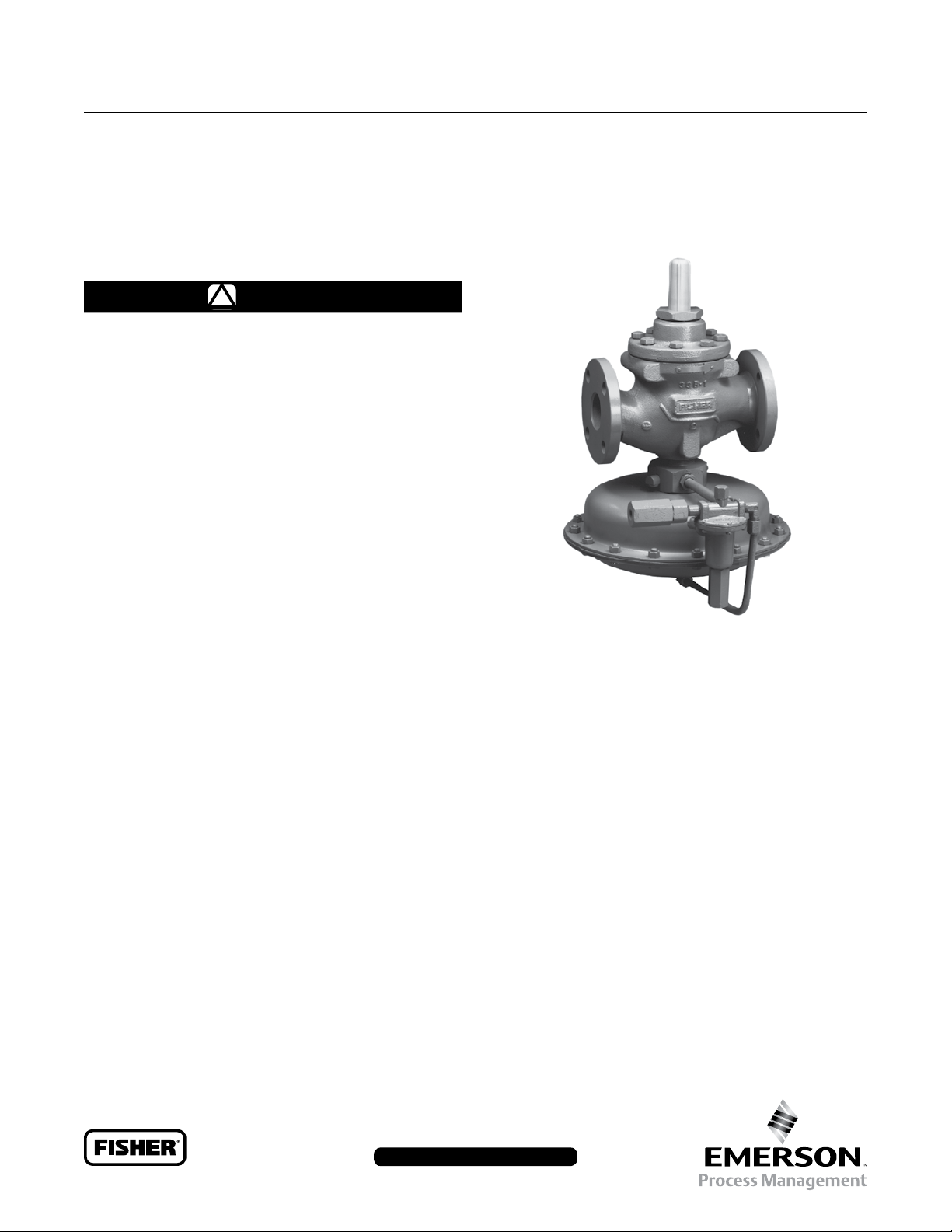
W6956
Figure 1. Type 1098-EGR
valve is also covered when a 61 Series pilot is used.
Instructions and parts lists for monitoring pilots and
other equipment used with this regulator are found in
separate manuals.
Description
Introduction
Scope of the Manual
This manual describes and provides instructions
and parts list for Type 1098-EGR or 1098H-EGR
regulator complete with a standard P590 Series
lter and either a 6350 Series regulator, a 61 Series
pilot or a Type Y600AM pilot. The Type 1806 relief
www.fisherregulators.com
Types 1098-EGR and 1098H-EGR regulators provide
economical and accurate pressure control in a
wide variety of applications: natural gas distribution
systems; fuel gas supply to industrial boilers, furnaces,
ovens and mixers; and large commercial/industrial
establishments such as shopping centers and schools.
They are also used in plant air service and in liquid
service where a slow stroking time (approximately
30 to 90 seconds) is desired on both opening and
closing the main valve.
D100339X012
Page 2
Types 1098-EGR and 1098H-EGR
The Specications section lists pressure limitations and other specications for various Types 1098-EGR and
1098H-EGR constructions. Specications for a given regulator as it originally comes from the factory are stamped
on nameplates located on both the actuator and main valve body, while the pilot control spring range is displayed
on the pilot spring case and the pilot restriction code is stamped on the pilot body (S = standard gain, L = low gain
and H = high gain).
Body Sizes and End Connection Styles
See Table 1
Main Valve Maximum Inlet Pressure
(1)
400 psig / 27.6 bar or body rating limit
whichever is lower
Maximum Pilot Supply Pressure
(1)(2)
600 psig / 41.4 bar
Outlet Pressure Ranges
See Table 2
Main Valve Flow Direction
In through the seat ring and out through the cage
Pressure Registration
External
Temperature Capabilities
Nitrile (NBR):
-20 to 180°F / -29 to 82°C
Fluorocarbon (FKM):
0 to 300°F / -18 to 149°C,
Water is limited to 0 to 200°F / -18 to 93°C
Maximum and Minimum Differential Pressures
See Table 4
Actuator Sizes and Maximum Pressures
See Table 3
Main Valve Flow Characteristic
Linear (standard), Whisper Trim
™
or
Quick opening
1. The pressure/temperature limits in this Instruction Manual or any applicable standard limitation should not be exceeded.
2. For stability or overpressure protection, a reducing regulator may be installed upstream of the pilot according to the Installation section.
Ethylenepropylene (EPDM):
-20 to 275°F / -29 to 135°C
Options
• NACE Construction
• Boiler Fuel Construction
• Aqueous Service Construction
• Monitor Conguration
• Noise Abatement Trim
(1)
Table 1. Body Sizes and End Connection Styles
BODY SIZE
N PS DN
1 or 2 25 or 50 NPT, CL125 FF or CL250 RF NPT, CL150 RF, CL300 RF, CL600 RF, BWE, SWE or PN 16/25/40
3, 4 or 6 80, 100 or 150 CL125 FF or CL250 RF CL150 RF, CL300 RF, CL600 RF, BWE or PN 16/25/40
8 x 6 or 12 x 6 200 x 150 or 300 x 150 - - - - CL150 RF, CL300 RF, CL600 RF or BWE
2
CAST IRON STEEL OR STAINLESS STEEL
Page 3
Types 1098-EGR and 1098H-EGR
Table 2. Outlet Pressure Ranges
PILOT TYPE
6351
6352
14 in. w.c. to 2 psig
6353
(1)
6354L
(2)
6354M
(2)
6354H
61L
61LD
61LE
7 in. w.c. to 2 psig
61H 10 to 65 0.69 to 4.5 Green Stripe 0Y066427022
61HP
7 to 16 in. w.c.
Y600AM
1. Without diaphragm limiter.
2. With diaphragm limiter.
15 in. w.c. to 1.2 psig
ACTUATOR TYPE ACTUATOR SIZE
1098
40 (standard)
1098H 30 350 24.1 400 27.6
OUTLET PRESSURE RANGE
psig bar
3 to 20
5 to 35
35 to 100
2 to 10
3 to 40
35 to 125
35 mbar to 0.1 bar
0.21 to 1.4
0.35 to 2.4
2.4 to 6.9
0.14 to 0.69
0.21 to 2.8
2.4 to 8.6
SPRING COLOR SPRING PART NUMBER
Green
Unpainted
Red
Yellow
Black
Yellow
Red
1B986027212
1B788327022
1K748527202
14A9672X012
14A9673X012
1E392527022
1K748527202
85 to 200 5.9 to 13.8 Blue 1L346127142
175 to 220 12.1 to 15.2 Blue 1L346127142
200 to 300 13.8 to 20.7 Green 15A9258X012
1 to 5
2 to 10
5 to 15
10 to 20
15 to 45
35 to 100
100 to 300
4 to 8 in. w.c.
1.2 to 2.5
2.5 to 4.5
4.5 to 7
17 mbar to 0.1 bar
0.07 to 0.3
0.14 to 0.69
0.35 to 1.0
0.69 to 1.4
1.0 to 3.1
2.4 to 6.9
6.9 to 20.7
10 to 20 mbar
17 to 4 mbar
37 mbar to 0.08 bar
0.08 to 0.17
0.17 to 0.31
0.31 to 0.48
Red
Yellow
Blue
Brown
Green
Yellow
Blue
Red
Red
Unpainted
Yellow
Green
Light Blue
Black
1B886327022
1J857827022
1B886427022
1J857927142
1B886527022
1E392527022
1D387227022
1D465127142
1B653827052
1B653927022
1B537027052
1B537127022
1B537227022
1B537327052
Table 3. Actuator Sizes and Maximum Pressures
OUTLET CONTROL PRESSURE EMERGENCY CASING PRESSURE
30
70
psig bar psig bar
100
75
50
6.9
5.2
3.4
115
82
65
7.9
5.6
4.5
Table 4. Maximum and Minimum Differential Pressures for Main Valve Selection
BODY SIZE
SPRING PART
NUMBER
SPRING
COLOR
MAXIMUM ALLOWABLE
DIFFERENTIAL PRESSURE
(1)
Size 30 Actuator Size 40 Actuator Size 70 Actuator
NPS DN psig bar psig bar psig bar psig bar
14A9687X012 Green 60 4.1 3.5 0.24 2.5 0.17 1 0.07
1 25
14A9680X012 Blue 125 8.6 5 0.34 3 0.21 1.5 0.10
14A9679X012 Red 400
(3)
27.6
(3)
7 0.48 5 0.34 2.5 0.17
14A6768X012 Yellow 20 1.4 - - - - - - - - - - - - - - - - 1 0.07
2 50
14A6626X012 Green 60 4.1 4 0.28 3 0.21 1.5 0.10
14A6627X012 Blue 125 8.6 6 0.41 5 0.34 2 0.14
14A6628X012 Red 400
(3)
27.6
(3)
11 0.76 10 0.69 3 0.21
14A6771X012 Yellow 20 1.4 - - - - - - - - - - - - - - - - 1 0.07
3 80
14A6629X012 Green 60 4.1 5 0.34 4 0.28 2 0.14
14A6630X012 Blue 125 8.6 8 0.55 6 0.41 2.5 0.17
14A6631X012 Red 400
(3)
27.6
(3)
14 0.97 11 0.76 4 0.28
14A6770X012 Yellow 20 1.4 - - - - - - - - - - - - - - - - 1.3 0.09
4 100
14A6632X012 Green 60 4.1 10 0.69 5 0.34 2.5 0.17
14A6633X012 Blue 125 8.6 13 0.90 8 0.55 3 0.21
14A6634X012 Red 400
(3)
27.6
(3)
22 1.5 13 0.90 5 0.34
15A2253X012 Yellow 20 1.4 - - - - - - - - - - - - - - - - 2.2 0.15
6, 8 x 6
or 12 x 6
1. Maximum inlet pressure is equal to set pressure plus maximum differential.
2. Requires special 6300 Series pilot construction without integral relief valve and with external Type 1806 40 psid / 2.8 bar d relief valve.
3. Should not exceed the body rating limit. Use this pressure value or the body rating limit, whichever is lower.
150, 200 x 150
or 300 x 150
14A9686X012 Green 60 4.1 13 0.90 9.5 0.66 4 0.28
14A9685X012 Blue 125 8.6 19 1.3 14 0.97 6 0.41
15A2615X012 Red 400
(3)
27.6
(3)
(2)
28
MINIMUM DIFFERENTIAL PRESSURE
REQUIRED FOR FULL STROKE
(2)
1.9
19 1.3 8 0.55
3
Page 4

Types 1098-EGR and 1098H-EGR
Table 5. Supply Pressure Settings Required for the Type 95H Regulator
SUPPLY PRESSURE
BODY SIZE
NPS DN psig bar psig bar psig bar psig bar psig bar psig bar
1 25
2 50
3 80
4 100
6 or 8 x 6
1. The pressures shown in the table are the minimum supply pressures required by the pilot. If the inlet pressure is less than shown, an external pilot supply is necessary.
150 or
200 x 150
TYPE EGR
SPRING COLOR
Green
Blue
Red
Green
Blue
Red
Green
Blue
Red
Green
Blue
Red
Green
Blue
Red
Red Unpainted Yellow Green Light Blue Black
6
0.41
7
0.48
8
0.55
6
0.41
8
0.55
13
0.90
7
0.48
9
0.62
14
0.97
8
0.55
11
0.76
16
1.1
13
0.90
17
1.2
22
1.5
6
0.41
7
0.48
8
0.55
6
0.41
8
0.55
13
0.90
7
0.48
9
0.62
14
0.97
8
0.55
11
0.76
16
1.1
13
0.90
17
1.2
22
1.5
Type Y600AM Spring Color
7
0.48
8
0.55
9
0.62
7
0.48
9
0.62
14
0.97
8
0.55
10
0.69
15
1.0
9
0.62
12
0.83
17
1.2
14
0.97
18
1.2
23
1.6
8
10
11
9
11
16
10
12
17
11
14
19
15
20
25
0.55
0.69
0.76
0.62
0.76
1.1
0.69
0.83
1.2
0.76
0.97
1.3
1.0
1.4
1.7
11
0.76
13
0.90
14
0.97
12
0.83
14
0.97
19
1.3
13
0.90
15
1.0
20
1.4
14
0.97
17
1.2
22
1.5
18
1.2
23
1.6
28
1.9
13
0.90
14
0.97
15
1.0
13
0.90
15
1.0
20
1.4
14
0.97
16
1.1
21
1.5
15
1.0
18
1.2
23
1.6
20
1.4
24
1.7
29
2.0
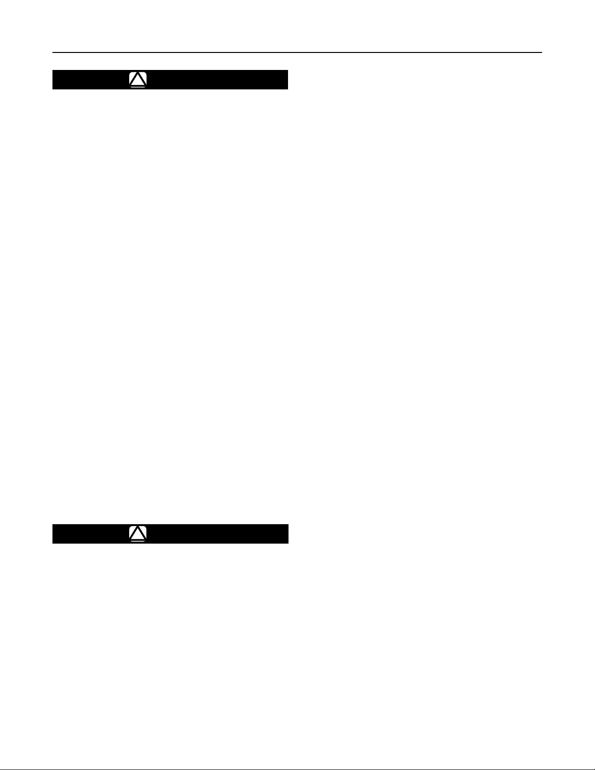
Principle of Operation
The pilot-operated Types 1098-EGR and 1098H-EGR
regulators both use inlet pressure as the operating
medium, which is reduced through pilot operation to load
the actuator diaphragm. Outlet or downstream pressure
opposes loading pressure in the actuator and also
opposes the pilot control spring. The Type 1098-EGR
regulator operation schematic is shown in Figure 2.
In operation, assume that outlet pressure is below
the pilot control setting. Control spring force on the
pilot diaphragm opens the pilot valve plug providing
additional loading pressure to the actuator diaphragm.
This loading pressure forces the actuator stem
forward, opening the main valve plug via a bump
connection. The upward motion of the plug allows gas
to ow through the cage into the downstream system.
When downstream demand has been satised, outlet
pressure tends to increase, acting on the pilot and
actuator diaphragms. This pressure exceeds the pilot
control spring setting, moving the pilot diaphragm
away and letting the valve plug spring (Type 6351,
61 Series or Type Y600AM pilots) or bellows
(Types 6352 through 6354M pilots) close the pilot
valve plug (unbalanced in the Type 6351 or 61 Series
pilots but balanced in the Types 6352 through
6354M pilots). Excess loading pressure on the
actuator diaphragm escapes downstream through the
bleed hole (Type 6351 pilot), bleed orice (61 Series
pilot), restriction (Types 6352 through 6354M pilots) or
xed restrictor (Type Y600AM pilot).
Reduced actuator loading pressure permits the main
valve to close. The combination of main valve spring
force and valve plug imbalance provides positive valve
plug shutoff against the port and upper seals.
To protect the Type 1098 or 1098H actuator diaphragm
from excessive differential pressure, the 6300 Series
pilots have a relief valve that allows loading pressure
to bleed downstream at approximately 25 psig / 1.7 bar
differential across the actuator diaphragm. An external
relief valve (Type 1806) is required when differential is
higher than 25 psi / 1.7 bar or when using the
61 Series or Y600AM pilots.
A mounting assembly for a 40 psi / 2.8 bar differential
relief valve is available for the Type 1098-EGR.
The standard 25 psi / 1.7 bar differential relief valve
construction is integrally mounted between the loading
and downstream pressures in the 6351 through
6354 Series regulating pilots. Both differential relief
valves protect the main regulator diaphragm from
damage that may occur from too high differential
between the loading pressure and downstream pressure.
The 40 psi / 2.8 bar differential relief valve construction
is designed specically for the red main valve spring
selection in the NPS 6 / DN 150 Type 1098-EGR-6354
with the size 30 actuator. This construction uses the
Type 1806H relief valve (with a setting of 40 psi / 2.8 bar)
to relieve excess loading pressure and does not interfere
with the normal operation of the regulator.
4
Page 5

TYPE 6351
TYPE 6352,
6353 OR 6354
Types 1098-EGR and 1098H-EGR
TYPE 1098-EGR
A6563
INLET PRESSURE
OUTLET PRESSURE
ATMOSPHERIC PRESSURE
LOADING PRESSURE
TYPE 1098-EGR WITH 6350 SERIES PILOT
TYPE 1098-EGR
TYPE 1806
A6641
INLET PRESSURE
OUTLET PRESSURE
ATMOSPHERIC PRESSURE
LOADING PRESSURE
TYPE 61LD
TYPE 1098-EGR WITH TYPE 61LD PILOT AND TYPE 1806 RELIEF VALVE
Figure 2. Operational Schematics
5
Page 6

Types 1098-EGR and 1098H-EGR
TYPE 95H
TYPE 1098-EGR
OPTIONAL:
TYPE 112 RESTRICTOR
TYPE Y600AM
M1008
TYPE 1098-EGR WITH TYPE Y600AM PILOT AND TYPE 95H PRESSURE SUPPLY REGULATOR
INLET PRESSURE
OUTLET PRESSURE
ATMOSPHERIC PRESSURE
LOADING PRESSURE
PILOT SUPPLY PRESSURE
Installation and Startup
WARNING
!
Personal injury, equipment damage or
leakage due to escaping accumulated
gas or bursting of pressure-containing
parts may result if this regulator is
overpressured or is installed where service
conditions could exceed the limits given
appropriate nameplate or where conditions
exceed any ratings of the adjacent piping
or piping connections. To avoid such
injury or damage, provide pressurerelieving or pressure-limiting devices to
prevent service conditions from exceeding
those limits.
FIXED RESTRICTOR
Figure 2. Operational Schematics (continued)
Additionally, physical damage to the
regulator may result in personal injury
and property damage due to escaping
accumulated gas. To avoid such injury
and damage, install the regulator in a
safe location.
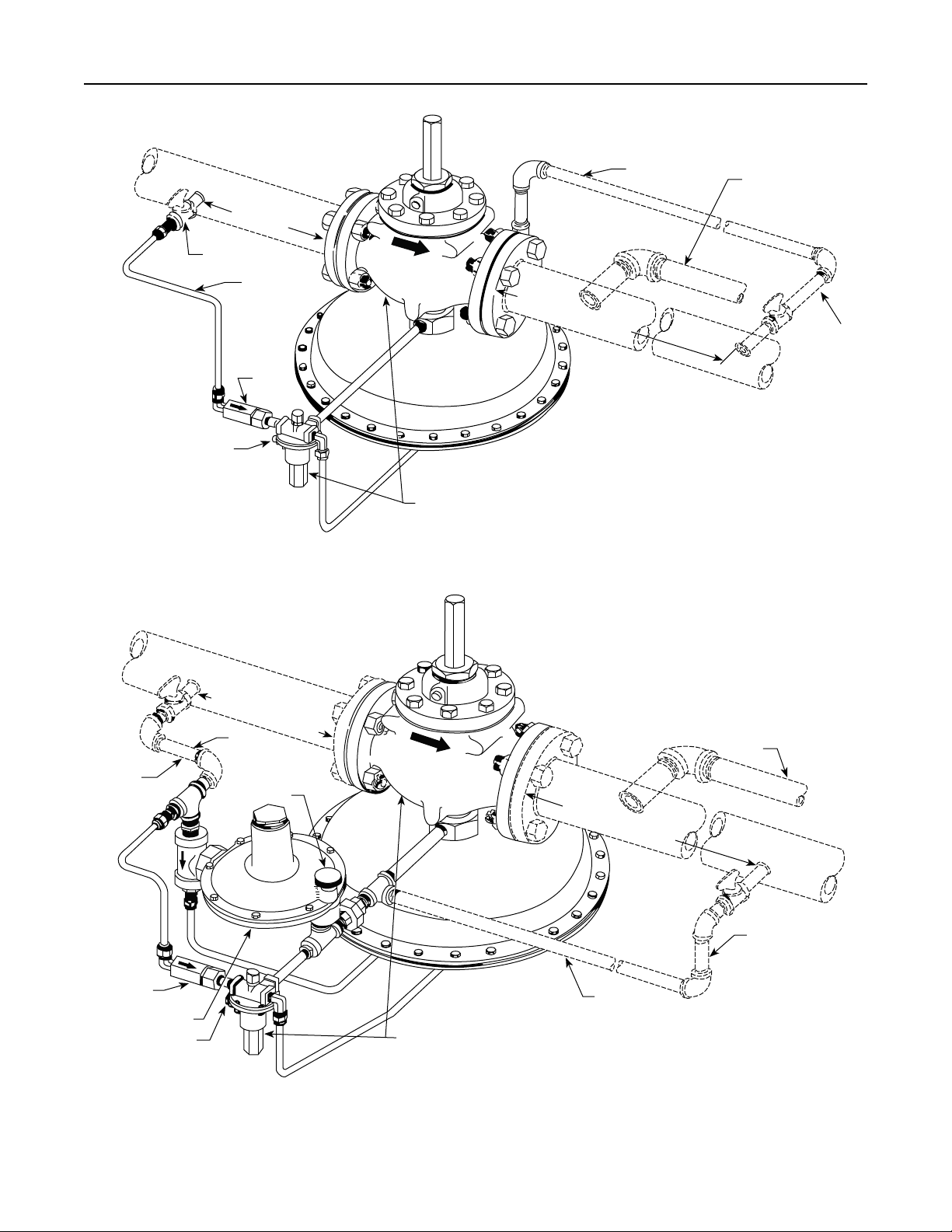
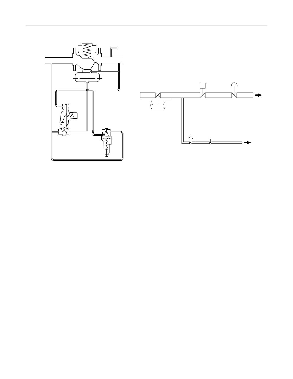
Standard Single-Pilot Regulator
(Figure 3)
Installations
A Type 1098-EGR or Type 1098H-EGR regulator
bleeds no gas to the atmosphere, making it suitable for
installation in pits or other enclosed locations without
elaborate venting systems. This regulator can also be
installed in pits subject to ooding by venting the pilot
spring case above the expected ood level so that the
pilot diaphragm is exposed to atmospheric pressure.
6
Page 7
Types 1098-EGR and 1098H-EGR
48A6566-A
B1622
4 MAIN PIPE
DIAMETERS
PIPE
PILOT
SUPPLY
LINE
FILTER
VENT
10 MAIN PIPE DIAMETERS
TYPE 1098-EGR OR 1098H-EGR REGULATOR
WITH STANDARD 6350 SERIES PILOT
Figure 3. Standard Single-Pilot Installation
CONTROL LINE
TO PILOT LIGHT (IF
USED FOR BOILER
FUEL INSTALLATION)
n
13 mm
PIPE
I
13 mm PIPE
FILTER
TYPE Y600AM
AUXILIARY PILOT
48A6566-A
B1622
4 MAIN PIPE DIAMETERS
VENT
PILOT
SUPPLY LINE
VENT
10 MAIN PIPE DIAMETERS
CONTROL
LINE
TYPE 1098-EGR SIZE 70 REGULATOR WITH QUICK OPENING CAGE
AND STANDARD TYPE 6352 WORKING PILOT
Figure 4. Typical Dual-Pilot Boiler Fuel Installation
TO PILOT
LIGHT
n.
13 mm PIPE
7
Page 8

Types 1098-EGR and 1098H-EGR
Note
Normal pressure drop assists shutoff.
Therefore, leakage may result during any
reverse pressure drop condition.
1. Use qualied personnel when installing, operating
and maintaining regulators. Before installing,
inspect the main valve, pilot and tubing for any
shipment damage or foreign material that may
have collected during crating and shipment. Make
certain the body interior is clean and the pipelines
are free of foreign material. Apply pipe compound
only to the external pipe threads with a screwed
body or use suitable line gaskets and good bolting
practices with a anged body.
With a weld end body, be sure to remove the trim
package, including the gasket, according to the
Maintenance section before welding the body into
the line. Do not install the trim package until any
post-weld heat treatment is completed. If heat
treating, prevent scale buildup on all machined
guiding and sealing surfaces inside the body and
at the bonnet ange / body joint.
Note
the valve body.
2. Install a three-valve bypass around the regulator
if continuous operation is necessary during
maintenance or inspection. The pilot may be eld-
changed to the opposite-side mounting position
by swapping the pilot pipe nipple to the opposite
bonnet tapping.
3. To keep the pilot spring case vent from being
plugged or the spring case from collecting moisture,
corrosive chemicals or other foreign material, point
the vent down or otherwise protect it. To remotely
vent the standard pilot, remove the vent and install
obstruction-free tubing or piping into the 1/4 NPT
vent tapping. Provide protection on a remote vent by
installing a screened vent cap into the remote end of
the vent pipe.
4. Run a 3/8 in. / 9.5 mm outer diameter or larger
pilot supply line from the upstream pipeline to
the lter inlet as shown in Figure 3. Do not make
the upstream pipeline connection in a turbulent
area, such as near a nipple, swage or elbow. If
the maximum pilot inlet pressure could exceed the
pilot rating, install a separate reducing regulator
in the pilot supply line. Install a hand valve in the
pilot supply line and provide vent valves to properly
isolate and relieve the pressure from the regulator.
5. Attach a 1/2 NPT downstream pressure control
line downstream of the regulator in a straight run
of pipe, as shown in Figure 3. Do not make the tap
near any elbow, swage or nipple that might cause
turbulence. Connect the other end of the control
line to the bonnet connection. Install a hand valve
in the control line to shut off the control pressure
when the bypass is in use.
6. If a quick acting solenoid is to be installed
downstream of the regulator, the regulator
and solenoid should be located as far apart as
practical. This maximizes the gas piping volume
between the regulator and solenoid and
improves the regulator response to quick-changing
ow rates.
WARNING
!
A regulator may vent some gas to
the atmosphere. In hazardous or
accumulate and cause personal injury,
explosion. Vent a regulator in hazardous
gas service to a remote, safe location
away from air intakes or any hazardous
location. The vent line or stack opening
must be protected against condensation
or clogging.
8
7. Consult the appropriate instruction manual for
installation of an optional Type 662 pneumatic
or electric remote control drive unit. For optional
remote pneumatic loading of a 6350 or 61 Series
pilot, make the loading piping connections to the
1/4 NPT vent connection.
Pre-startup Considerations
Before beginning the startup procedures in this section,
make sure the following conditions are in effect:
• Block valves isolate the regulator.
• Vent valves are closed.
• Hand valves are closed.
Page 9
Types 1098-EGR and 1098H-EGR
CAUTION
Introduce pilot supply pressure into
the regulator before introducing any
downstream pressure or internal damage
may occur due to reverse pressurization
of the pilot and main valve components.
Always use pressure gauges to monitor downstream
pressure during startup. Procedures used in putting
this regulator into operation must be planned
accordingly if the downstream system is pressurized
by another regulator or by a manual bypass.
Note
For proper operation, pilot supply
pressure must exceed control pressure
the actuator nameplate as minimum
differential pressure.
The only adjustment necessary on a Type 1098-EGR
or 1098H-EGR regulator is the pressure setting of
the pilot control spring. Turning the adjusting screw
clockwise into the spring case increases the spring
compression and pressure setting. Turning the
adjusting screw counterclockwise decreases the spring
compression and pressure setting.
Pilot Adjustment
To adjust standard 6350 Series pilots: Loosen the
locknut and turn the adjusting screw. Then tighten
the locknut to maintain the adjustment position. On
a standard Types 6352 through 6354M pilots, closing
cap must be removed before adjustment and
replaced afterward.
WARNING
!
To avoid possible personal injury from
a pressure-loaded pilot, carefully vent
the spring case before removing the
closing cap. Otherwise, trapped loading
pressure could forcefully eject the freed
closing cap.
To adjust the 61 Series or Type Y600AM pilots:
Remove the closing cap and turn the adjusting screw.
Any adjustments made should set the controlled
pressure within the appropriate spring range shown
in the Table 2.
Startup
1. Slowly open the pilot supply line hand valve.
2. Slowly open the upstream block valve and partially
open the downstream block valve for minimum
ow. Slowly open the hand valve in the
control line.
3. Adjust the pilot setting, if necessary.
4. Completely open the downstream block valve.
5. Slowly close the bypass valve, if any.
Dual-Pilot Boiler Fuel Control
Applications
Boiler Fuel Pressure Control
To enhance proper operation and adequate response
to negative pressure shock condition in low differential
pressure boiler fuel control applications, use the
Type 1098-EGR boiler fuel conguration:
• Type 1098-EGR with Type 6352 pilot
• Size 70 Actuator
• Quick Opening Cage
• Yellow Main Spring
• Type Y600AM or 627M Auxiliary Pilot
mounted in parallel with the Type 6352 pilot
To provide faster response, two pilots mounted in
parallel sense the downstream pressure. The
Type 6352 pilot is the primary controlling pilot and the
Type Y600AM or 627M auxiliary pilot stands by until it
senses a negative pressure shock condition.
The auxiliary pilot opens, allowing additional ow into
the actuator, increasing the stroking speed
and providing faster response. See Figure 5 for
schematic. The quick-opening cage allows maximum
capacity at shorter travels to decrease stroking time
in opening and closing directions. The service
conditions should not exceed 20 psig / 1.4 bar
maximum inlet pressure and 10 psi / 0.69 bar
maximum differential pressure.
Supply the boiler pilot light gas with the Type 1098-EGR.
The pilot light gas supply line should branch off the
main fuel line downstream of the Type 1098-EGR and
include a separate regulator to control the nal pilot
light gas pressure, if required (see Figure 6). This
allows the Type 1098-EGR to have its main valve plug
just off the seat waiting for the sudden negative shock
created when the boiler solenoid valve is opened to
light the boiler to the high re load. This installation
practice signicantly increases the stroking speed of
the Type 1098-EGR. See Figure 6 for schematic.
9
Page 10
Types 1098-EGR and 1098H-EGR
TYPE 1098-EGR SIZE 70
WITH QUICK OPENING CAGE
20 psibar MAXIMUM
GAS
SUPPLY
SAFTEY SHUT-OFF VALVE
TO BOILER
TYPE 6352
WORKING PILOT
TYPE Y600AM
AUXILIARY PILOT
E0711
Figure 5. Boiler Fuel Conguration
Note
Modulating solenoid load valves provide
one position to the other, effectively
preventing sudden pressure changes in
the system. Alternately, a snap-acting
solenoid valve can be furnished with a
characterized valve plug that, by allowing
maximum capacity to be reached at a
greater proportion of total travel, slows
the action slightly. This action does
not control shock as effectively as
modulating solenoid valves.
Installation
1. Perform the Standard Single-Pilot Regulator
Installation section through step 3, making sure
that the regulator is installed with the actuator
below the main valve as shown in Figure 4.
2. Run a 1/2 in. / 13 mm or larger pilot supply line
from the upstream pipeline to the 1/2 NPT supply
connection in the pipe tee as shown in Figure 4. Do
not make the connection in a turbulent area, such as
near a nipple, swage or elbow. If the maximum pilot
TYPE
1098-EGR
PILOT
GAS
SUPPLY
PILOT GAS
REGULATOR
E0710
Figure 6. Boiler Fuel Conguration Installation Guide
FAST-ACTING
LOAD VALVE
TO PILOT LIGHT
inlet pressure could exceed the pilot rating, install a
separate regulator in the pilot supply line and provide
vent valves so that pressure can be properly isolated
and relieved from the regulator.
3. Attach a 1/2 NPT downstream pressure control line
ten pipe diameters downstream of the regulator in
a straight run of pipe. Do not make the tap near
any elbow, swage or nipple, which might cause
turbulence. Connect the other end of the control
line to the 1/4 NPT connection in the control pipe
tee as shown in Figure 4. Install a hand valve in the
control line to shut off the control pressure when
the bypass is in use. Also use the hand valve to
dampen out pulsations, which may cause instability
or cycling of the regulator.
4. Consult the appropriate instruction manual for
installation of an optional pneumatic or electric
remote control drive unit. For optional remote
pneumatic loading of 6350 or 61 Series pilots,
make the loading piping connections to the
1/4 NPT vent connection.
10
Page 11
Types 1098-EGR and 1098H-EGR
Type 1098-EGR
1098-EGR Working Monitor
6350 SERIES PILOT
6350 SERIES PILOT
March 2007
Type 1098-EGR
TYPE Y600M OR 627-109
MONITORING PILOT
6350 SERIES PILOT
A6788
INLET PRESSURE
OUTLET PRESSURE
ATMOSPHERIC PRESSURE
LOADING PRESSURE
INTERMEDIATE PRESSURE
Startup
TYPE Y600M OR 627-109
MONITORING PILOT
Figure 7. Typical Working Monitor Installation
2. Connect another downstream pressure control line
1. Slowly open the pilot supply line hand valve.
2. Slowly open the upstream block valve and partially
open the downstream block valve for minimum ow.
3. Slowly open the hand valve in the control line and
make sure that the standby pilot is set far enough
below the working pilot so that the standby pilot
remains closed during normal operation. For
example, with nal desired settings of 11 in. w.c. /
For two typical monitoring pilots, Table 7 gives
27 mbar for the working pilot and 10 in. w.c. /
25 mbar for the standby pilot, begin by reducing
the working pilot setting far enough below
10 in. w.c. / 25 mbar for the working pilot to
shut off. Then set the standby pilot for an outlet
pressure of 10 in. w.c. / 25 mbar. Finally, set the
working pilot for an outlet pressure of 11 in. w.c. /
27 mbar. Table 6 shows how close the standby
pilot can be set to the working pilot setting.
4. Completely open the downstream block valve.
Startup
On a working monitor installation (Figure 7), be sure that
the second-stage working regulator is set to operate at a
pressure lower than the Type 1098-EGR or 1098H-EGR
working monitor regulator. To do this, increase the setting
5. Slowly close the bypass valve, if any.
Working Monitor (Figure 7)
Installation
of the monitoring pilot until the working pilot is in control of
the intermediate pressure and the second-stage working
regulator is in control of the downstream pressure. If this
is not done, the monitoring pilot tries to take control of the
downstream pressure.
6350 SERIES PILOT
and hand valve (Figure 7) to the monitoring pilot
according to the monitoring pilot instruction manual.
Attach a 1/2 NPT pressure control line and hand
valve from the intermediate pressure pipeline to the
working monitor regulator. Pipe supply pressure
between the monitoring pilot and the working
monitor regulator according to the monitoring
pilot manual.
the spread between normal distribution pressure
and the minimum pressure at which the working
monitor regulator can be set to take over if the
working regulator fails to open.
1. For both working monitor regulator and working
regulator, perform the Standard Single-Pilot
Regulator Installation section through step 6.
1. Slowly open the upstream block valve and
the hand valves in both pilot supply lines. This
energizes both pilots so that their setpoints can
be adjusted. Partially open the downstream block
valve for minimum ow.
11
Page 12
Types 1098-EGR and 1098H-EGR
Table 6. Auxiliary Pilot Selection (Fast Stroke Dual Pilot)
SIZE CONSTRUCTION
Type Y600AM 1/4 6.4
3/4
NPT
Type 627M 1/2 13 5 to 10 0.34 to 0.69 10B3076X012 Yellow
Construction
Type 161AYW pilot and 150 psig /
10.3 bar maximum allowable
pilot inlet pressure
Type 627-109 pilot and 150 psig /
10.3 bar maximum allowable pilot
inlet pressure for cast iron body
or 750 psig / 51.7 bar maximum
allowable pilot inlet pressure for
malleable iron or steel body
ORIFICE SPRING RANGE
In. mm psi bar
4 to 8 in. w.c. 10 to 20 mbar 1B653827052 Red
7 to 16 in. w.c. 17 to 40 mbar 1B653927022 Unpainted
15 in. w.c. to 1.2 psi 37 mbar to 0.08 bar 1B537027052 Yellow
1.2 to 2.5 0.08 to 0.17 1B537127022 Green
2.5 to 4.5 0.17 to 0.31 1B537227022 Light Blue
4.5 to 7 0.31 to 0.48 1B537327052 Black
Table 7. Working Monitor Performance
MONITORING PILOT INFORMATION
Spring Range
psig bar
3 to 12 in. w.c.
11 to 25 in. w.c.
25 in. w.c. to 2.5 psi
2.5 to 4.5 psi
4.5 to 7 psi
5 to 20
15 to 40
35 to 80
70 to 150
130 to 200
7 to 30 mbar
27 to 62 mbar
62 mbar to 0.17 bar
0.17 to 0.31
0.31 to 0.4
0.34 to 1.4
1.0 to 2.8
2.4 to 5.5
4.8 to 10.3
9.0 to 13.8
SPRING
NUMBER
Spring Part Number
1B653927022
1B537027052
1B537127022
1B537227022
1B537327052
10B3076X012
10B3077X012
10B3078X012
10B3079X012
SPRING
COLOR
MINIMUM PRESSURE AT WHICH
WORKING MONITOR REGULATOR
3 in. w.c. / 7 mbar over
normal distribution pressure
14 in. w.c. / 34 mbar over
normal distribution pressure
normal distribution pressure
5.0 psig / 0.34 bar over
normal distribution pressure
MINIMUM PRESSURE
AT WHICH AUXILIARY
PILOT CAN BE SET
1 in. w.c. / 2 mbar
Under working
pilot setpoint
6 in. w.c. / 14 mbar
Under working
pilot setpoint
8 in. w.c. / 21 mbar
Under working
pilot setpoint
CAN BE SET
3.0 psig / 0.21 bar over
2. To enable intermediate pressure adjustment with
the working monitor regulator, slowly open the
hand valve in the intermediate pressure control line.
3. To enable downstream pressure adjustment with
the second-stage working regulator, slowly open
the hand valve in the control line to this regulator.
4. Adjust the setting of the monitoring pilot to
establish the desired emergency downstream
pressure, which is to be maintained in the event
of open failure of the second-stage working
regulator. The emergency downstream pressure
should exceed the desired downstream pressure
by at least the amount listed in Table 7. The steps
followed to set the monitoring pilot may vary with
each piping situation; however, the basic method
remains the same. The following sub steps a
and b may be used as examples for setting the
monitoring pilot:
a. Increase the outlet pressure setting of the second-
stage working regulator until the monitoring pilot
takes control of the downstream pressure. Adjust
the monitoring pilot setting until the desired
emergency downstream pressure is achieved.
Then, readjust the second-stage working regulator
to establish the desired downstream pressure.
b. Install special piping (not shown in Figure 7) so
that the monitoring pilot senses the intermediate
pressure. The intermediate pressure then appears
to the monitoring pilot as if it was increased
downstream pressure and the monitoring pilot
controls and reduces the intermediate pressure.
Adjust the monitoring pilot setting until the desired
emergency downstream pressure is achieved
at the intermediate pressure stage. Then slowly
close the special piping and open up
the monitoring downstream control line for
normal service.
5. Slowly open the downstream block valve.
6. Slowly close the bypass valve, if any.
12
Page 13
Type 1098-EGR
Type 1098-EGR Upstream or Downstream “Wide-Open” Monitor
6350 SERIES PILOT
PILOT SUPPLY REGULATOR
6350 SERIES PILOT
July 2011
Type 1098-EGR
A6789
INLET PRESSURE
OUTLET PRESSURE
LOADING PRESSURE
MONITOR LOADING PRESSURE
ATMOSPHERIC PRESSURE
INTERMEDIATE PRESSURE
PILOT SUPPLY REGULATOR
6350 SERIES PILOT
Figure 8. Typical Wide-Open Monitor Installations
Types 1098-EGR and 1098H-EGR
6350 SERIES PILOT
NOTICE
Adjustment Recommendations for
Monitor Applications
Low amplitude/high frequency monitor trim oscillations
can occur if the monitor regulator pressure setting is
adjusted too closely to the working regulator pressure
setting and/or if the monitor pilot supply regulator
pressure setting is adjusted too closely to the monitor
regulator pressure setting. The monitor pressure
setting should be adjusted so it is at minimum two
times the pilot proportional band pressure above the
working regulator pressure setting. The monitor pilot
supply pressure setting should be adjusted so it is at
minimum 5 psig / 0.34 bar plus the monitor minimum
differential pressure above the working regulator
pressure setting. These adjustments must be made
such that other governing pressure limits, such as
casing ratings, pilot maximum differential pressures or
regulatory limits, are not exceeded.
Wide-Open Monitor (Figure 8)
Either the upstream or downstream regulator can be
the monitor regulator. During normal operation, the
monitoring regulator is standing wide open with the
reduction to distribution pressure being taken across
the working regulator. Only in case of open failure of
the working regulator does the wide open monitoring
regulator take control at its slightly higher setting.
Regardless of which regulator is used as the monitor,
it should be equipped with a pilot supply regulator set
to limit the pilot supply pressure to 10 to 15 psig / 0.69
to 1.0 bar above control pressure. Since the pilot on
the monitoring regulator is wide open during normal
operation, the pilot supply regulator prevents differential
relief valve chatter on the monitoring regulator pilot.
Installation
1. For both the wide-open monitoring regulator and
the working regulator, perform the Standard SinglePilot Regulator Installation section through step 6.
2. Connect the control line of the wide-open
monitoring regulator (Figure 8) to downstream
piping near the working regulator control line
connection. During normal operation the wide-
open monitoring regulator stands wide-open
with the pressure reduction being taken across
the working regulator. Only in case of working
regulator failure does the wide-open monitoring
regulator take control at its slightly higher setting.
Startup
Repeat this procedure in turn for each regulator in
the installation.
1. Slowly open the pilot supply line hand valve.
2. Slowly open the upstream block valve and
partially open the downstream block valve for
minimum ow.
13
Page 14
Types 1098-EGR and 1098H-EGR
BODY FLANGE
SEAT RING
SCREWS INTO CAGE
P1507
Figure 9. Trim Package Removal
CAGE SCREWS INTO
BODY FLANGE
3. Slowly open the hand valve in the control line
and adjust the pilot setting if necessary. Set the
monitoring regulator at a slightly higher control
pressure than the working regulator.
4. Completely open the downstream block valve.
5. Slowly close the bypass valve, if any.
Shutdown
Installation arrangements vary, but in any installation it
is important that the valves be opened or closed slowly
and that the outlet pressure be vented before venting
inlet pressure to prevent damage caused by reverse
pressurization of the pilot or main valve. The following
steps apply to the typical installation as indicated.
P1508
Figure 10. Seat Ring / Cage Removal or Installation
Using Body as Holding Fixture
4. Slowly open the upstream pipeline vent valve.
Allow all pressure to bleed out of both the piping
and the pilot.
Working Monitor
1. Slowly close the downstream block valve and the
hand valve in the downstream pressure control line.
2. Slowly close the upstream block valve and the
hand valves in both pilot supply lines.
3. Slowly open all vent valves and permit all pressures to
bleed out of the piping and regulators.
Maintenance
Single-Pilot, Dual-Pilot Regulator or
Wide-Open Monitor
As well as applying to a single-pilot regulator (Figure 3),
the steps in this procedure are also valid for a dualpilot regulator (Figure 4) or a wide-open monitoring
installation (Figure 8) and just need to be repeated for
each regulator in such an installation.
1. Slowly close the downstream block valve. If the
control line is downstream of the block valve, also
close the hand valve in the control line.
2. Slowly close the upstream block valve and the
hand valve in the pilot supply line.
3. Slowly open the vent valve in the downstream
pipeline. If the control line is downstream of the
block valve, also open the vent valve in the control
line. Permit all pressure to bleed out.
14
Regulator parts are subject to normal wear and must be
inspected and replaced as necessary. The frequency
of inspection and replacement of parts depends upon
the severity of service conditions or the requirements
of local, state and federal regulations. Due to the
care Emerson™ takes in meeting all manufacturing
requirements (heat treating, dimensional tolerances,
etc.), use only replacement parts manufactured or
furnished by Emerson.
The stem O-rings (key 6, Figure 14) on the Type 1098
or 1098H actuator can be lubricated during regularly
scheduled maintenance, using the grease tting
(key 28, Figure 14). Stem O-rings can be checked
for damage during normal operation by line pressure
leakage or unexpected grease extrusion from the
actuator vent (key 27, Figure 14). All O-rings, gaskets
and seals should be lubricated with a good grade of
general-purpose grease and installed gently rather
than forced into position. Be certain that the nameplates
Page 15

Types 1098-EGR and 1098H-EGR
(key 13, Figure 14) are updated to accurately indicate
any eld changes in equipment, materials, service
conditions or pressure settings.
WARNING
!
To avoid personal injury resulting
from sudden release of pressure,
isolate the regulator from all pressure
and cautiously release trapped
pressure from the regulator before
attempting disassembly.
Type EGR Main Valve
Replacing Quick-Change Trim Package
Perform this procedure if the entire trim package
is replaced. Key numbers for both the complete
main valve and its trim package are referenced in
Figures 12 and 13. Some replacement trim package
assembly numbers are listed in a table in the parts list.
Note
All disassembly, trim change and
reassembly steps in this section may be
performed with the regulator in the main
line and without disconnecting the pilot
supply or control lines.
1. Remove the cap screws (key 3) with a cast iron
body or remove the hex nuts (key 29, not shown)
with a steel body. Pry the body ange (key 2) from
the valve body (key 1) and lift out the trim package.
2. Perform any required inspection, cleaning or
maintenance on the exposed surfaces of the valve
body (key 1) or trim package. Replace the gasket
(key 4) or cage O-ring (key 17) as necessary.
3. On a pre-built replacement trim package, check
indicator zeroing by unscrewing the indicator
protector (key 19) and seeing if the ange of the
indicator nut (key 22) lines up evenly with the
bottom marking on the indicator scale (key 18).
If not, remove the indicator scale and separate
the indicator nut and hex nut (key 8). Hold the
indicator scale against the indicator tting (key 5)
with the scale base resting against the shoulder of
the tting and turn the indicator nut until its ange
is aligned with the bottom scale marking. Then
lock both nuts against each other and install the
indicator scale and protector.
19
10
18
37
22
35
8
7
5
21
36
6
23
9
28
10C1212
Figure 11. Types 1098-EGR and 1098H-EGR
Travel Indicator Assembly
4. Coat the cage seating surface of the valve body
(key 1) web and the body ange (key 2) seating
surfaces of the valve body neck with a good grade
of general-purpose grease. Install the trim package
and secure it evenly with the cap screws
(key 3) or stud bolt nuts (key 29, not shown).
No particular trim package orientation in the body
is required.
Replacing Travel Indicator Assembly
The Types 1098-EGR and Type 1098H-EGR travel
indicator assemblies now incorporate a redesigned
O-ring retainer (key 6), Polytetrauoroethylene (PTFE)
backup rings (key 36) and an additional indicator tting
(key 35).
When performing maintenance on the original
Type 1098-EGR or 1098H-EGR body ange,
travel indicator replacement is recommended. The
redesigned travel indicator assembly is incorporated
into all Quick-Change Trim Kits (e.g. 25A3170X012)
and on the Travel Indicator Kits (see table by size).
The elastomer repair kits contain the components for
the redesigned travel indicator assembly.
15
Page 16

Types 1098-EGR and 1098H-EGR
Type EGR Main Valve Cap Screw (key 3) Torque
SIZE TORQUE
NPS DN Ft-lbs m
1 25 75 to 95 102 to 129
2 50 55 to 70 75 to 95
3 80 100 to 130 136 to 176
4 100 160 to 200 217 to 271
6, 8 x 6, 12 x 6
150, 200 x 150,
300 x 150
275 to 300 373 to 407
1. Remove the travel indicator assembly by removing
lower indicator tting (key 5) from the body ange
(key 2).
2. Coat the threads of the lower indicator tting
(key 5) with a good grade of general-purpose grease.
3. Install travel indicator assembly (10C1212), torque
to 40 ft-lbs / 54 N•m.
4. Check indicator zeroing by unscrewing the
indicator protector (key 19) and seeing if the ange
of the indicator nut (key 22) lines up evenly with
the bottom marking on the indicator scale (key 18).
If not, remove the indicator scale and separate
the indicator nut and hex nut (key 8). Hold the
indicator scale against the indicator tting (key 5)
with the scale base resting against the shoulder of
the tting and turn the indicator nut until its ange
is aligned with the bottom scale marking. Then
lock both nuts against each other and install the
indicator scale and protector.
Replacing Trim Parts
Perform this procedure when inspecting, cleaning or
replacing individual trim package parts. Key numbers
are referenced in Figures 12 and 13.
Note
O-ring, travel indicator parts or optional
travel stop (key 32) in step 1 can be
gained without removing the body
1. Remove the indicator tting (key 5) and attached
parts. Proceed to step 5 if only maintenance on the
tting or attached parts is performed.
2. Remove the cap screws (key 3) on a cast iron
body or remove the hex nuts (key 29, not shown)
on a steel body and pry the body ange (key 2)
loose from the valve body (key 1).
3. Use the valve body (key 1) as a holding xture
if desired. Flip the body ange (key 2) over and
anchor it on the valve body as shown in Figure 10,
removing the pipe plug (key 31) rst if necessary.
4. To gain access to the port seal (key 12), upper seal
(key 15) or valve plug (key 16) part, unscrew the
seat ring (key 13) from the cage (key 11) and the
cage from the body ange (key 2). For leverage,
a wrench handle or similar tool may be inserted
into the seat ring slots (Figure 10) and a strap
wrench may be wrapped around a standard or a
Whisper Trim™ Cage or a soft bar may be inserted
through the windows of a standard cage. To remove
the piston ring (key 14) and/or plug O-ring (key 20),
remove the valve plug (key 16) from the body
ange, insert a screwdriver into the precut fold
over area of the piston ring and unfold the piston
ring. Proceed to step 6 if no further maintenance
is necessary.
5. To replace the body ange (key 2) or gain access
to the spring (key 9), indicator stem (key 10), stem
O-ring (key 7), spring seat (key 28), E-ring (key 23)
or optional travel stop (key 32), remove the
indicator protector (key 19) and indicator scale
(key 18). Since some compression is left in the
spring,carefully remove the anged nut (key 22)
and hex nut (key 8). A screwdriver may be
inserted through the press-t bushing (key 6) to
remove the stem O-ring without removing the
bushing. If necessary, unscrew the travel stop (if
used) and unclip the E-ring from the indicator stem.
6. Replace and lubricate parts such as the gasket
(key 4) and cage O-ring (key 17) as necessary,
making sure that if the port (key 12) and upper
seals (key 15) were removed they are installed in
their retaining slots with the grooved sides
facing out. Also lubricate any other surfaces as
necessary for ease of installation. No further main
valve maintenance is necessary if just the
indicator tting (key 5) and attached parts
were removed.
7. Install the plug O-ring (key 20) and piston ring
(key 14) onto the valve plug (key 16). Insert the
valve plug into the body ange (key 2), install the
cage (key 11) plus upper seal (key 15) and O-ring
(key 17) into the body ange and then install the
seat ring (key 13) plus port seal (key 12) into the
16
Page 17

Types 1098-EGR and 1098H-EGR
cage. Apply a thin coating of lubricant to seals for
protection during assembly. Use the valve body
(key 1) as a holding xture during this step as
shown in Figure 10 and insert a wrench handle
(or similar tool) into the seat ring slots for leverage
when tightening the seat ring and cage.
8. Remove the upside-down body ange (key 2) if it
was anchored on the body. Coat the cage
(key 11) seating surfaces of the valve body
(key 1) web and the body ange (key 2) seating
surfaces of the valve body neck with a good grade
of general-purpose grease. Install the body ange
on the body and secure it evenly with the cap
(key 3) screws or stud bolt nuts (key 29, not
shown). Except on the NPS 1 / DN 25 body, which
does not use it, the pipe plug (key 31) must be
installed in the side tapping of the ange for
proper operation.
9. Make sure that the ange (key 2) and stem O-rings
(key 7) and the bushings are installed in the
indicator tting (key 5). Orient the spring seat
(key 28) as shown in Figure 12 and attach it with
the E-ring (key 23) to the slotted end of the
indicator stem (key 10). Install the travel stop
(key 32) (if used) on the spring seat and then
install the spring (key 9).
10. Being careful not to cut the stem O-ring (key 7)
with the stem threads, install the indicator tting
(key 5) down over the indicator stem (key 10)
until resting on the spring (key 9). Install the hex
nut (key 8) and then the anged indicator nut
(key 22) on the indicator stem, pushing on the
tting if necessary to provide sufcient stem
thread exposure. To maintain clearance for
indicator part installation, draw up the spring seat
(key 28) by turning the hex nut down on the stem
until the threads bottom.
11. Install the indicator tting (key 5) with attached
parts into the body ange (key 2). Back the hex
nut off until the spring completely closes the
valve plug (key 16) against the port (key 12) and
upper seals (key 15), as indicated by stem
threads showing between this nut and the tting.
Hold the indicator scale (key 18) against the
tting with the scale base resting against the
shoulder of the tting and turn the indicator nut
(key 22) until its ange is aligned with the bottom
scale marking. Then lock both nuts against each
other and install the indicator scale and
protector (key 19).
P590 Series Filter
Perform this procedure to clean or replace lter parts in a
standard Type P593-1 or P594-1 lter assembly. Remove
the following (as shown in Figure 15): lter body (key 1),
machine screw (key 4), gasket (key 7), two at washers
(key 5) and lter element (key 2).
Upon reassembly, one of the at washers must go
between the lter element and lter head (key 3) and
the other must go between the lter element and
gasket. Use a good grade of pipe thread sealant on
the lter head pipe threads.
Type 6351 Pilot
Perform this procedure if changing the control spring
for one of a different range or if inspecting, cleaning or
replacing any other pilot parts. Pilot key numbers are
referenced in Figure 16 and mounting key numbers in
Figure 24, 25, 26 or 28.
Note
The body assembly (key 1) may remain
on the pipe nipple (key 23, Figure 24
or key 39, Figure 28) unless the entire
pilot is replaced. The optional bonnet
(key 2) for a Type 662 electric remote
control drive unit may remain installed
during maintenance.
1. To gain access to the diaphragm assembly (key 7),
control spring (key 9) or spring seat (key 8),
loosen the locknut (key 11, not used with Type 662
mounting) and turn the adjusting screw (key 10)
counterclockwise until compression is removed
from the spring. Remove the machine screws
(key 12) and separate the body assembly (key 1)
from the bonnet (key 2).
2. Inspect the removed parts and replace as
necessary. Ensure the registration and bleed
holes in the pilot body are free of debris. After
assembly, make sure of the proper control spring
setting according to the Startup section and
remark the spring case if necessary.
3. To replace the valve plug (key 4), remove the body
plug (key 3) to let the valve spring (key 6) and
inner valve assembly (key 4) drop freely from the
body (key 1). Inspect the removed parts, replace
if necessary. Make sure the plug seating surfaces
are free from debris. Inspect body plug O-ring
(key 3), replace if necessary. Type 6351 pilots
17
Page 18

Types 1098-EGR and 1098H-EGR
manufactured before May 1999 need to have the
body plug gasket and the body plug replaced with
a new body plug assembly (key 3), which includes
the body plug and the body plug O-ring. Install the
body plug O-ring over the body plug. Stack the
valve spring and the inner valve assembly on the
body plug assembly (key 3) and install the body
plug assembly with stacked parts into the body.
Types 6352 through 6354M Pilots
Perform this procedure if changing the control spring
for one of a different range or if inspecting, cleaning
or replacing any other pilot parts. Pilot part key
numbers are referenced in Figure 17. Mounting
key numbers are referenced in Figure 24 for
single-pilot constructions and in Figures 26 and 28 for
dual-pilot constructions.
Note
The body (key 1) may remain on the
pipe nipple (key 23, Figure 24 or key 39,
Figure 28) unless the entire pilot
is replaced.
1. To gain access to the diaphragm assembly (key 5),
diaphragm limiter (key 23) if used, control spring
(key 6), restriction (key 22), stem guide (key 8) or
spring seat (key 7), remove the closing cap (key 11),
loosen the locknut (key 10) and turn the adjusting
screw (key 9) counterclockwise until compression
is removed from the spring. Remove the machine
screws (key 14) and separate the body from the
spring case (key 2).
2. Inspect the removed parts and replace as
necessary. Make sure the restriction and the
registration hole in the body are free from debris.
After assembly, make sure of the proper control
spring setting according to the Startup section
and remark the spring case if necessary.
3. To replace the valve plug (key 4) or bellows
O-ring (key 17), remove the body plug (key 3)
and body plug gasket (key 12). Be careful to
keep the bellows assembly (key 16) from falling
out and possibly getting lost while removing the
valve plug. Inspect the removed parts and replace
as necessary. Make sure the valve plug seating
surfaces are free from debris.
61 Series Pilot and Type 1806 Relief Valve
Perform this procedure if changing the control spring
for one of a different range or if inspecting, cleaning or
replacing relief valve or any other pilot parts. Pilot part
key numbers are referenced in Figures 18 and 19
and mounting part and relief valve key numbers in
Figure 25.
1. Remove the pilot from the pipe nipple (key 24)
unless just the control spring is to be changed.
2. To gain access to the control spring or other
internal parts, remove the closing cap assembly
(key 5) and relieve control spring (key 7)
compression by turning the adjusting screw
(key 6) counterclockwise. Change the control
spring and install the adjusting screw and closing
cap assembly if no other maintenance will be
performed. Make sure of the proper control spring
setting according to the Installation and Startup
section and restamp the nameplate if necessary.
3. For any other internal maintenance, relieve control
spring compression according to step 2. Then
remove the cap screw (key 20) and separate the
pilot into three sections: spring case (key 1), body
(key 2) and bottom cover (key 3).
4. To inspect the two diaphragms (keys 14 and 15)
thoroughly, remove the diaphragm nut (key 11), hex
nut (key 19) and the upper and lower relay heads
(keys 16 and 17). The projecting prong in the body
may be used as the restraining member to keep the
yoke (key 4) from turning while removing the nuts.
Also inspect the O-ring (key 12) and replace any
parts as necessary.
5. Take the yoke (key 4) and attached parts out of the
body to examine the disk holder assembly (key 9).
Remove the relay orice (key 8) to check for
clogging and replace if necessary.
6. To replace the disk holder assembly, rst unscrew
the bleed orice (key 10). Remove it and the
associated parts. Then unscrew the disk
(key 9) holder assembly from the bleed valve
(key 26) to gain access to the relay spring
(key 13). Clean or replace any parts as necessary
before reassembling.
7. Upon reassembly, pay particular attention to the
following assembly suggestions:
18
Page 19

Types 1098-EGR and 1098H-EGR
a. Before replacing the diaphragm case (key 2)
or spring case (key 1), be sure the yoke assembly
is positioned so that it will not bind or rub on the
prong in the relay body.
b. Avoid wrinkling the diaphragms (key 14 and 15)
when replacing the diaphragm case (key 2) and
spring case (key 1).
c. Replace the diaphragm case (key 2), carefully
working the upper relay diaphragm (key 14) into
the recess in the diaphragm case. If the
diaphragm case rocks with respect to the pilot
body, the diaphragm is probably wrinkled.
d. Replace the spring case (key 1), using care to
smooth the lower relay diaphragm (key 15)
evenly into the recess in the pilot body.
e. Install the eight cap screws (key 20), tightening
them down evenly in a crisscross pattern to
avoid crushing the diaphragm. Recommended
nal torque on these cap screws is 10 to
12 ft-lbs / 14 to 16 N•m.
8. After assembly, make sure of the proper control
spring setting according to the Installation and
Startup section and restamp the nameplate
(key 27) if necessary.
9. To gain access to the Type 1806 relief valve,
disconnect the relief tubing at the connector
tting and unscrew the relief valve. Make sure the
spring closes the ball or replace the relief valve
if necessary. Install the relief valve back in the
pipe tee (key 16) and reconnect the relief tubing
(key 18) and connector tting.
Type Y600AM Pilot
3. Inspect and replace the orice (key 5) if necessary.
Protect the orice seating surface during
disassembly and assembly. Lubricate the threads
of the replacement orice with proper amount of
anti-seize lubricant and install with 29 to 38 ft-lbs /
39 to 52 N•m of torque.
4. To replace the disk assembly (key 13), remove the
cotter pin (key 15). If not necessary, skip to step 7.
5. Install the disk assembly (key 13) and secure it
with the cotter pin (key 15).
6. Place backup ring (key 48) into the body (key 1).
Then place the body seal O-ring (key 11) into
the body.
7. Place the diaphragm casing (key 4) on the body
(key 1). Secure the the diaphragm casing to the
body with the cap screws (key 2) using 7 to
9 ft-lbs / 9.5 to 12 N•m.
Diaphragm and Spring Case Area
This procedure is for gaining access to the spring,
diaphragm, lever assembly stem and Type Y600AM
stem O-ring. All pressure must be released from the
diaphragm casing before performing these steps.
1. Remove the closing cap (key 22) and turn the
adjusting screw (key 35) counterclockwise to
remove the compression from the spring (key 6).
2. If the only maintenance is to change the control
spring, take out the control spring and replace
with the desired spring. Turn the adjusting screw
(key 35) clockwise to compress the spring to
the desired outlet pressure setting according to
the Installation and Startup section and restamp
the nameplate if necessary. Skip to step 11.
Body Area
This procedure is for gaining access to the disk assembly,
orice and body O-ring. All pressure must be released
from the diaphragm casing and the disk assembly must
be open, before these steps can be performed. Part key
numbers are referenced in Figure 21.
1. Remove the cap screws (key 2) and separate the
diaphragm casing (key 4) from the body (key 1).
2. Remove and inspect the body seal O-ring (key 11)
and the backup ring (key 48).
3. If further maintenance to the internal diaphragm
casing parts is required, remove the hex nuts (key 23,
not shown) and cap screws (key 24). Remove the
diaphragm (key 10) plus attached parts by tilting
them so that the pusher post (key 8) slips off the lever
assembly (key 16). To separate the diaphragm from
the attached parts, unscrew the cap screw (key 38)
from the pusher post (key 8). If the only maintenance
needed is to replace the diaphragm parts, skip to
step 7.
19
Page 20

Types 1098-EGR and 1098H-EGR
4. To replace the lever assembly (key 16), remove
the machine screws (key 17). To replace the stem
(key 14) or stem O-ring (key 30), also perform
Body Area Maintenance procedure steps 1 and 4
and pull the stem (key 14) out of the diaphragm
casing (key 4). Grease the replacement stem
O-ring (key 30) with a good grade of lubricant and
install it on the stem (key 14).
5. Install the stem (key 14) into the diaphragm casing
(key 4) and perform Body Area Maintenance
procedure steps 6 through 8 as necessary.
6. Install the lever assembly (key 16) into the stem
(key 14) and secure the lever assembly with the
machine screws (key 17).
7. Hold the pusher post (key 8) and place diaphragm
assembly parts on the pusher post in the following
order: diaphragm (key 10), diaphragm head (key 7),
lower spring seat (key 50) and washer (key 36) and
secure with diaphragm cap screw (key 38) using 7 to
9 ft-lbs / 9.5 to 12 N•m of torque.
8. Install the pusher post (key 8) and attached parts onto
the lever (key 16).
9. Install the control spring (key 6) and spring case
(key 3) on the diaphragm casing (key 4) so that the
vent assembly (key 26) is correctly oriented and
secure them with the cap screws (key 24) and hex
nuts (key 23) to nger tightness only.
10. Turn the adjusting screw (key 35) clockwise until
there is enough control spring (key 6) force to provide
proper slack to the diaphragm (key 10). Using a
crisscross pattern, nish tightening the cap screws
(key 24) and hex nuts to 5 to 6 ft-lbs / 6.8 to 8.1 N•m
of torque. Finish turning the adjusting screw to the
desired outlet pressure setting.
11. Install the closing cap (key 22).
Type 95H Supply Pressure Regulator
This section includes instructions for disassembly and
assembly of replacement parts. All key numbers refer
to Figure 23.
1. Unscrew the valve plug guide (key 5) from the
body (key 1). The valve plug spring (key 10) and
the valve plug (key 4) will normally come out of the
body along with the valve plug guide.
2. Inspect the seating surface of the valve plug (key 4),
being sure that the composition surface (or polished
steel surface) of the valve plug is not damaged.
Replace if damaged.
3. Inspect the seating edge of the orice (key 3).
If damaged, unscrew the orice from the body
and replace it with a new part. If no further
maintenance is required, reassemble the regulator
in the reverse of the above steps. When installing
the valve plug guide (key 5) coat the threads and
sealing surface with sealant to ensure an adequate
metal-to-metal seal.
4. To inspect the diaphragm (key 12) or other
internal parts, loosen the locknut (key 17) and
turn the adjusting screw (key 15) to remove all
spring compression.
5. Remove the diaphragm case cap screws (key 16)
and lift off the spring case (key 2). Remove the
upper spring seat (key 9) and regulator spring
(key 11). Remove the lower spring seat (key 8).
6. Remove the diaphragm (key 12) and examine for
damage. Replace if damaged.
7. With diaphragm removed, check to be sure the
pressure registration hole is completely open and
free of all obstructions.
8. Reassemble in reverse order of the previous steps.
Lubricate the upper spring seat (key 9) and the
exposed threads of the adjusting screw (key 15).
Before tightening cap screws (key 16) be sure to
install the adjusting screw, if completely removed and
turn it down to obtain diaphragm slack. This allows
proper positioning of the diaphragm to permit full
travel of the valve plug (key 4). Complete reassembly
procedures and temporarily install a gauge in place
of the pipe plug (key 52). Turn the adjusting screw to
produce the desired outlet pressure values shown
in Table 2. Tighten the locknut to maintain the
desired setting.
20
Page 21

Types 1098-EGR and 1098H-EGR
Types 1098 and 1098H Actuator and Pilot
Mounting Parts
Perform this procedure if changing the actuator
or inspecting, cleaning or replacing actuator
and/or pilot mounting parts. Actuator part key
numbers are referenced in Figure 14 and mounting
part numbers in Figure 27, unless otherwise indicated.
1. The actuator and pilot(s) may be removed and
replaced as a unit by disconnecting the control line
and pilot supply line.
2. Access to all internal parts except the stem
O-rings, bearings and wiper (keys 6, 56 and 57)
may be gained without removing the bonnet
(key 3) or upper diaphragm case (key 2) from
the main valve or the pilot(s) from the bonnet
pipe nipple (key 23, Figure 24 or keys 37
and 39, Figure 28). Disconnect the loading
tubing (key 24, Figure 24, 26 or 28) from the
actuator elbow tting (key 25, Figure 24 or
key 41, Figure 28) and with a Type 61LD pilot
also disconnect the relief tubing (key 18,
Figure 25) from the tting tee.
3. Remove the cap screws (key 10), nuts (key 11),
lower diaphragm case (key 1), diaphragm (key 7)
and diaphragm plate (key 8). To separate the stem
(key 12) from the diaphragm plate (key 8), remove
the stem cap screw (key 9).
For the Type 1098 actuator, lubricate the case
O-ring (key 5) and install it in the bonnet (key 3).
Line up the holes in the upper diaphragm casing
(key 2) and the bonnet; insert and tighten the four
case cap screws (key 4) to secure the parts
together. Thread the bonnet into the main valve body.
6. Secure the diaphragm plate (key 8) to the stem
(key 12) with the stem cap screw (key 4). Lay the
entire diaphragm (key 7), diaphragm plate and
stem assembly into the lower diaphragm case
(key 1) so the diaphragm convolution laps up
over the diaphragm plate according to Figure 14.
Then install the stem slowly up into the bonnet
(key 3) to prevent stem or O-ring damage and
secure the lower diaphragm case to the upper
diaphragm case (key 2) with the cap screws
and nuts. Tighten the cap screws and nuts
evenly in a crisscross pattern to avoid crushing
the diaphragm.
7. Grease the stem O-rings through the zerk
tting (key 28) until excess grease emerges from
the vent (key 27).
8. Install the pipe nipple(s) and pilot(s) if they were
removed during maintenance. Connect the
actuator loading tubing if it was disconnected.
Parts Ordering
4. To remove the Type 1098 case O-ring
(key 5), unscrew the four case cap screws
(key 4), remove the upper diaphragm case
(key 2) and remove the case O-ring.
To remove the Types 1098 and 1098H stem
O-rings (key 6), remove the pilot(s) and pipe
nipple(s) if necessary. Unscrew either the
Type 1098 bonnet (key 3) or the Type 1098H
upper diaphragm case (key 2) and remove the
wiper ring, bearings and O-rings.
5. Lubricate both stem O-rings (key 6) and wiper ring
(key 57) and install them with the stem bearings
(key 56) in either the Type 1098 bonnet (key 3) or
in the Type 1098H upper diaphragm case (key 2).
For the Type 1098H actuator, thread the upper
diaphragm casing (key 2) into the main valve body.
Each Type 1098-EGR or 1098H-EGR regulator is
assigned a serial number or FS number which can be
found on the nameplates. Refer to this number when
contacting your local Sales Ofce for assistance or
when ordering replacement parts.
When ordering a replacement part, be sure to include
the complete 11-character part number from the
following parts list. Some commonly used trim packages
can be ordered according to the 11-character assembly
number given in the parts kits listed in the Parts List.
Parts List
Note
Except where indicated, sizes shown are
valve body sizes.
21
Page 22

Types 1098-EGR and 1098H-EGR
Parts List (continued)
Type EGR Main Valve (Figures 12 and 13)
Key Description Part Number
Elastomer Trim Parts kit (included are:
keys 4, 7, 12, 14, 15, 17, 20, 21, 36 and 37)
Nitrile (NBR)
NPS 1 / DN 25 R63EGX00112
NPS 2 / DN 50 R63EGX00122
NPS 3 / DN 80 R63EGX00132
NPS 4 / DN 100 R63EGX00142
NPS 6 / DN 150 R63EGX00162
Fluorocarbon (FKM)
NPS 1 / DN 25 R63EGXFK112
NPS 2 / DN 50 R63EGXFK122
NPS 3 / DN 80 R63EGXFK132
NPS 4 / DN 100 R63EGXFK142
NPS 6 / DN 150 R63EGXFK162
Ethylenepropylene (EPR)
NPS 1 / DN 25 R63EGXEP112
NPS 2 / DN 50 R63EGXEP122
NPS 3 / DN 80 R63EGXEP132
NPS 4 / DN 100 R63EGXEP142
NPS 6 / DN 150 R63EGXEP162
Actuator Parts kit (included are: keys 5, 6, 7, 56 and 57)
Size 30
Nitrile (NBR) R1098X00302
Fluorocarbon (FKM) R1098X00502
Size 40
Nitrile (NBR) R1098X00402
Fluorocarbon (FKM) R1098X00602
Size 70
Nitrile (NBR) R1098X00702
Quick Change Trim Kit (see Figure 13 for included keys)
60 psi / 4.1 bar spring color green
Cast Iron Body Flange
NPS 1 / DN 25 25A3170X012
NPS 2 / DN 50 25A3170X102
NPS 3 / DN 80 25A3170X152
NPS 4 / DN 100 25A3170X222
NPS 6 / DN 150 25A3170X272
Steel Body Flange
NPS 1 / DN 25 25A3170X422
NPS 2 / DN 50 25A3170X452
NPS 3 / DN 80 25A3170X372
NPS 4 / DN 100 25A3170X482
NPS 6 / DN 150 25A3170X512
NPS 8 x 6 / DN 200 x 150 25A3170X532
125 psi / 8.6 bar spring color blue
Cast Iron Body Flange
NPS 1 / DN 25 25A3170X032
NPS 2 / DN 50 25A3170X082
NPS 3 / DN 80 25A3170X142
NPS 4 / DN 100 25A3170X192
NPS 6 / DN 150 25A3170X282
Steel Body Flange
NPS 1 / DN 25 25A3170X432
NPS 2 / DN 50 25A3170X382
NPS 3 / DN 80 25A3170X462
NPS 4 / DN 100 25A3170X492
NPS 6 / DN 150 25A3170X342
NPS 8 x 6 / DN 200 x 150 25A3170X542
400 psi / 27.6 bar spring color red
Cast Iron Body Flange
NPS 1 / DN 25 25A3170X052
NPS 2 / DN 50 25A3170X112
1. Part included in trim package assembly can be ordered according to the parts kit trim package.
Key Description Part Number
Cast Iron Body Flange (continued)
NPS 3 / DN 80 25A3170X172
NPS 4 / DN 100 25A3170X242
NPS 6 / DN 150 25A3170X312
Steel Body Flange
NPS 1 / DN 25 25A3170X442
NPS 2 / DN 50 25A3170X332
NPS 3 / DN 80 25A3170X472
NPS 4 / DN 100 25A3170X502
NPS 6 / DN 150 25A3170X522
NPS 8 x 6 / DN 200 x 150 25A3170X552
Parts Kit, Quick Change Travel Indicator Kit
(included are: keys 10, 6, 35, 5, 8, 7 and 36 (2 required);
keys 21, 18, 22, 23, 37, 19, 28 and 9)
60 psi / 4.1 bar spring color green
NPS 1 / DN 25 10C1212X042
NPS 2 / DN 50 10C1212X012
NPS 3 / DN 80 10C1212X022
NPS 4 / DN 100 10C1212X032
NPS 6 / DN 150 10C1212X052
125 psi / 8.6 bar spring color blue
NPS 1 / DN 25 10C1212X092
NPS 2 / DN 50 10C1212X062
NPS 3 / DN 80 10C1212X072
NPS 4 / DN 100 10C1212X082
NPS 6 / DN 150 10C1212X102
400 psi / 27.6 bar spring color red
NPS 1 / DN 25 10C1212X142
NPS 2 / DN 50 10C1212X112
NPS 3 / DN 80 10C1212X122
NPS 4 / DN 100 10C1212X132
NPS 6 / DN 150 10C1212X152
1 Valve Bodies See following table
2 Body Flange
Cast iron, ENC
NPS 2 / DN 50 25A3168X012
NPS 3 / DN 80 24A9034X012
NPS 4 / DN 100 25A2309X012
NPS 6, 8 x 6 or 12 x 6 /
DN 150, 200 x 150 or 300 x 150 34A8172X012
WCC steel, ENC, heat-treated
NPS 1 / DN 25 24A6779X012
NPS 2 / DN 50 25A2254X012
NPS 3 / DN 80 25A2300X112
NPS 4 / DN 100 24A9032X012
NPS 6, 8 x 6 or 12 x 6 /
DN 150, 200 x 150 or 300 x 150 34A7152X012
CF8M Stainless steel, ENC (NACE)
NPS 1 / DN 25 24A6779X062
NPS 2 / DN 50 25A2254X082
NPS 3 / DN 80 25A2300X012
NPS 4 / DN 100 24A9032X042
NPS 6, 8 x 6 or 12 x 6 /
DN 150, 200 x 150 or 300 x 150 34A7152X052
3 Cap Screw, plated steel (use with cast iron and
steel body)
NPS 1 / DN 25 (4 required) 1R281124052
NPS 2 / DN 50 (8 required) 1A453324052
NPS 3 / DN 80 (8 required) 1A454124052
NPS 4 / DN 100 (8 required) 1A485724052
NPS 6, 8 x 6 or 12 x 6 /
DN 150, 200 x 150 or 300 x 150 (12 required) 1U513124052
(1)
(1)
22
Page 23

Types 1098-EGR and 1098H-EGR
Key 1, Type EGR Main Valve Bodies
MATERIAL END CONNECTION
NPT 34B7611X012 38A8845X012
Cast Iron
WCC Steel
CF8M Stainless steel / NACE
NACE WCC Steel
CL125 FF 34B8630X012 38A8847X012
CL250 RF 37B5950X012 38A8846X012
NPT 37B5946X012 38A8848X012
CL150 RF 37B5947X012 38A8853X012
CL300 RF 37B5948X012 38A8849X012
CL600 RF 37B5949X012 38A8844X012
SWE GE05951X012 GE05958X012
SCH 40 BWE GE05953X012 GE05957X012
SCH 80 BWE GE05954X012 GE05959X012
PN 16/25/40 GE05956X012 GE05960X012
NPT 37B5946X032 38A8848X032
CL150 RF 37B5947X032 38A8853X072
CL300 RF 37B5948X032 38A8849X032
CL600 RF 37B5949X032 38A8844X032
SWE GE05951X022 GE05958X022
SCH 40 BWE GE05953X022 GE05957X022
SCH 80 BWE GE05954X022 GE05959X022
PN 16/25/40 GE05956X022 GE05960X022
NPT - - - - - - - - - - - 38A8848X022
CL150 RF 37B5947X022 38A8853X052
CL300 RF 37B5948X022 38A8849X022
CL600 RF 37B5949X022 38A8844X022
Key 1, Type EGR Main Valve Bodies (continued)
MATERIAL END CONNECTION NPS 8 xx 150
Cast Iron
WCC Steel
CF8M Stainless steel / NACE
NACE WCC Steel
CL125 FF 38A8851X012 38A8865X012 38A8875X012 - - - - - - - - - - -
CL250 RF 38A8850X012 38A8854X012 38A7110X012 - - - - - - - - - - -
CL150 RF 38A8872X012 38A8867X012 38A7115X012 GE05973X012
CL300 RF 38A8871X012 38A8869X012 38A8873X012 GE05974X012
CL600 RF 38A8852X012 38A8866X012 38A8874X012 GE05975X012
SCH 40 BWE GE05962X012 GE05967X012 GE05971X012 - - - - - - - - - - -
SCH 80 BWE GE05963X012 GE05968X012 GE05970X012 - - - - - - - - - - -
PN 16 GE05965X012 GE05969X012 GE05972X012 - - - - - - - - - - -
CL150 RF 38A8872X052 38A8867X042 38A7115X032 - - - - - - - - - - -
CL300 RF 38A8871X052 38A8869X032 38A8873X032 - - - - - - - - - - -
CL600 RF 38A8852X042 38A8866X032 38A8874X032 - - - - - - - - - - -
SCH 40 BWE GE05962X022 GE05967X022 GE05971X022 GE05976X022
SCH 80 BWE GE05963X022 GE05968X022 GE05970X022 - - - - - - - - - - -
PN 16 GE05965X022 GE05969X022 GE05972X022 - - - - - - - - - - -
CL150 RF 38A8872X062 38A8867X032 38A7115X022 GE05973X022
CL300 RF 38A8871X042 38A8869X022 38A8873X022 GE05974X022
CL600 RF 38A8852X032 38A8866X022 38A8874X022 GE05975X022
23
Page 24

Types 1098-EGR and 1098H-EGR
Type EGR Main Valve
(Figures 12 and 13) (continued)
Key Description Part Number
3 Stud Bolt, Stainless steel (use with Stainless steel body)
(not shown)
NPS 1 / DN 25 (4 required) 1R284835222
NPS 2 / DN 50 (8 required) 1K242935222
NPS 3 / DN 80 (8 required) 1A378135222
NPS 4 / DN 100 (8 required) 1R369035222
NPS 6, 8 x 6 or 12 x 6 /
DN 150, 200 x 150 or 300 x 150 (12 required) 1A365635222
(1)
4*
Gasket, composition
NPS 1 / DN 25 14A6785X012
NPS 2 / DN 50 14A5685X012
NPS 3 / DN 80 14A5665X012
NPS 4 / DN 100 14A5650X012
NPS 6, 8 x 6 or 12 x 6 /
DN 150, 200 x 150 or 300 x 150 14A6984X012
(1)
5
Travel Indicator Fitting
Zinc-plated steel
NPS 1 / DN 25 T21117T0012
NPS 1 / DN 25 (NACE) T21117T0022
NPS 2, 3 or 4 / DN 50, 80 or 100 T21107T0012
NPS 6, 8 x 6 or 12 x 6 /
DN 150, 200 x 150 or 300 x 150 (NACE) T21120T0012
316-A Stainless steel
NPS 2, 3 or 4 / DN 50, 80 or 100 (NACE) T21107T0022
(1)
6
O-ring Retainer
416 Stainless steel (NACE) T14276T0012
(1)
7*
Travel Indicator Stem O-ring
Nitrile (NBR)
(1)
1E472706992
Fluorocarbon (FKM) 1N430406382
Ethylenepropylene (EPR) 1D6875X0092
(1)
8
Travel Indicator Hex Nut, plated steel 1A662228992
(1)
9
Spring, steel (standard) or Inconel® X-750 (NACE) See following table
(1)
10
Travel Indicator Stem
18-8 Stainless steel
NPS 1 / DN 25 T14311T0012
NPS 2 / DN 50 T14275T0012
NPS 3 / DN 80 T14312T0012
NPS 4 / DN 100 T14313T0012
NPS 6, 8 x 6 or 12 x 6 /
DN 150, 200 x 150 or 300 x 150 T14314T0012
Key Description Part Number
(1)
Travel Indicator Stem (continued)
10
316 Stainless steel (NACE)
NPS 1 / DN 25 T14311T0022
NPS 2 / DN 50 T14275T0022
NPS 3 / DN 80 T14312T0022
NPS 4 / DN 100 T14313T0022
NPS 6, 8 x 6 or 12 x 6 /
DN 150, 200 x 150 or 300 x 150 T14314T0022
11 Cage
Linear
(1)
, CF8M Stainless steel (NACE)
NPS 1 / DN 25 34B4136X012
NPS 2 / DN 50 34B5838X012
NPS 3 / DN 80 34B5839X012
NPS 4 / DN 100 34B5840X012
NPS 6, 8 x 6 or 12 x 6 /
DN 150, 200 x 150 or 300 x 150 34B5841X012
Whisper Trim
®
416 Stainless steel
NPS 1 / DN 25 24A2043X012
NPS 2 / DN 50 24A5707X012
NPS 3 / DN 80 24A5708X012
NPS 4 / DN 100 24A5709X012
NPS 6, 8 x 6 or 12 x 6 /
DN 150, 200 x 150 or 300 x 150 24A8174X012
316 Stainless steel, ENC
NPS 1 / DN 25 24A2043X022
NPS 2 / DN 50 24A5707X022
NPS 3 / DN 80 24A5708X042
NPS 4 / DN 100 24A5709X022
NPS 6, 8 x 6 or 12 x 6 /
DN 150, 200 x 150 or 300 x 150 24A8174X022
Quick Opening, cast iron, ENC
NPS 1 / DN 25 37A7211X012
NPS 2 / DN 50 37A7212X012
NPS 3 / DN 80 37A7213X012
NPS 4 / DN 100 37A7214X012
NPS 6, 8 x 6 or 12 x 6 /
DN 150, 200 x 150 or 300 x 150 37A7215X022
Key 9, Spring
BODY SIZE
NPS DN
1 25 - - - - 14A9687X012 14A9680X012 14A9679X012 11B6769X012 12B8326X012 10B1882X012
2 50 14A6768X012 14A6626X012 14A6627X012 14A6628X012 16A5501X012 16A5995X012 16A5499X012
3 80 14A6771X012 14A6629X012 14A6630X012 14A6631X012 16A5503X012 16A5996X012 16A5500X012
4 100 14A6770X012 14A6632X012 14A6633X012 14A6634X012 16A5506X012 16A5997X012 16A5998X012
6, 8 x 6 or
12 x 6
*Recommended spare part.
1. Part included in trim package assembly can be ordered according to the parts kit trim package.
Inconel® is a mark owned by Special Metals Corporation.
150, 200 x
150 or
300 x 150
Yellow
15A2253X012 14A9686X012 14A9685X012 15A2615X012 16A5510X012 16A5999X012 16A6000X012
Standard (Steel) NACE (Inconel
Green
Blue
24
SPRING
Red
Green
®
X-750)
Blue
Red
Page 25

Types 1098-EGR and 1098H-EGR
19
10
37
7
21
6
21
INDICATOR PLUG ASSEMBLY
27
18
22
8
35
5
35A3167
3
2
24
26
14
15
9
11
16 13 12
36
31
4
20
23
28
17
1
24 25
COMPLETE CAST IRON
FULL-CAPACITY MAIN VALVE ASSEMBLY
Figure 12. Type EGR Main Valve Construction
25
Page 26

Types 1098-EGR and 1098H-EGR
19 18
10 22
35 8
37 36
7 5
21 31
6 2
14 4
15 20
9 23
11 28
12 17
16 13
QUICK-CHANGE TRIM
25A3170
PACKAGE ASSEMBLY
Figure 13. Type EGR Main Valve Internal Constructions
Type EGR Main Valve
(Figures 12 and 13) (continued)
Key Description Part Number
12* Port Seal
Nitrile
NPS 1 / DN 25 14A6788X012
NPS 2 / DN 50 24A5673X012
NPS 3 / DN 80 24A5658X012
NPS 4 / DN 100 24A5643X012
NPS 6, 8 x 6 or 12 x 6 /
DN 150, 200 x 150 or 300 x 150 14A8175X012
Fluorocarbon (FKM)
NPS 1 / DN 25 14A8186X012
NPS 2 / DN 50 25A7412X012
NPS 3 / DN 80 25A7375X012
NPS 4 / DN 100 25A7469X012
NPS 6, 8 x 6 or 12 x 6 /
DN 150, 200 x 150 or 300 x 150 14A6996X012
Ethylenepropylene (EPR)
NPS 1 / DN 25 14A6788X022
NPS 2 / DN 50 24A5673X062
NPS 3 / DN 80 24A5658X062
NPS 4 / DN 100 24A5643X052
NPS 6, 8 x 6 or 12 x 6 /
DN 150, 200 x 150 or 300 x 150 14A8175X022
(NBR)
(1)
(standard)
32
28
26A3800
DETAIL OF OPTIONAL RESTRICTED
CAPACITY CONSTRUCTION
Key Description Part Number
(1)
13*
Seat Ring
416 Stainless steel
NPS 1 / DN 25, 1-5/16 in. / 33 mm port 24A6781X012
NPS 2 / DN 50, 2-3/8 in. / 60 mm port 24A5670X012
NPS 3 / DN 80, 3-3/8 in. / 86 mm port 24A5655X012
NPS 4 / DN 100, 4-3/8 in. / 111 mm port 24A5640X012
NPS 6 / DN 150, 7-3/16 in. / 183 mm port 24A6989X012
NPS 8 x 6 / DN 200 x 150, 7-3/16 in. /
183 mm port 38A4216X012
316 Stainless steel (NACE)
NPS 1 / DN 25, 1-5/16 in. / 33 mm port 24A6781X022
NPS 2 / DN 50, 2-3/8 in. / 60 mm port 24A5670X022
NPS 3 / DN 80, 3-3/8 in. / 86 mm port 24A5655X022
NPS 4 / DN 100, 4-3/8 in. / 111 mm port 24A5640X022
NPS 6 / DN 150, 7-3/16 in. / 183 mm port 24A6989X022
NPS 8 x 6 / DN 200 x 150, 7-3/16 in. /
183 mm port 38A4216X022
(1)
14*
Piston Ring
NPS 1 / DN 25, PTFE (clear) 14A6786X012
NPS 2 / DN 50, PTFE (clear) 14A5675X012
NPS 3 / DN 80, PTFE (clear) 14A5660X012
NPS 4 / DN 100, PTFE (clear) 14A5645X012
NPS 6, 8 x 6 or 12 x 6 / DN 150, 200 x 150
or 300 x 150, glass-lled, PTFE 14A6985X022
*Recommended spare part.
1. Part included in trim package assembly can be ordered according to the parts kit trim package.
26
Page 27

Type EGR Main Valve
(Figures 12 and 13) (continued)
Types 1098-EGR and 1098H-EGR
Key Description Part Number
15* Upper Seal
Nitrile (NBR)
(1)
(standard)
NPS 1 / DN 25 14A6789X012
NPS 2 / DN 50 24A5674X012
NPS 3 / DN 80 24A5659X012
NPS 4 / DN 100 24A5644X012
NPS 6, 8 x 6 or 12 x 6 /
DN 150, 200 x 150 or 300 x 150 14A8176X012
Fluorocarbon (FKM)
NPS 1 / DN 25 14A8187X012
NPS 2 / DN 50 25A7413X012
NPS 3 / DN 80 25A7376X012
NPS 4 / DN 100 25A7468X012
NPS 6, 8 x 6 or 12 x 6 /
DN 150, 200 x 150 or 300 x 150 14A8185X012
Ethylenepropylene (EPR)
NPS 1 / DN 25 14A6789X022
NPS 2 / DN 50 24A5674X062
NPS 3 / DN 80 24A5659X062
NPS 4 / DN 100 24A5644X052
NPS 6, 8 x 6 or 12 x 6 /
DN 150, 200 x 150 or 300 x 150 14A8176X022
(1)
16*
Valve Plug
416 Stainless steel
NPS 1 / DN 25 14A6780X012
NPS 2 / DN 50 24A6772X012
NPS 3 / DN 80 24A9421X012
NPS 4 / DN 100 24A8182X012
NPS 6, 8 x 6 or 12 x 6 /
DN 150, 200 x 150 or 300 x 150 24A6992X012
316 Stainless steel (NACE)
NPS 1 / DN 25 14A6780X022
NPS 2 / DN 50 24A6772X032
NPS 3 / DN 80 24A9421X022
NPS 4 / DN 100 24A8182X022
NPS 6, 8 x 6 or 12 x 6 /
DN 150, 200 x 150 or 300 x 150 24A6992X022
17* Cage O-ring
Nitrile (NBR)
(1)
(standard)
NPS 1 / DN 25 10A7777X012
NPS 2 / DN 50 10A7779X012
NPS 3 / DN 80 14A5688X012
NPS 4 / DN 100 10A3481X012
NPS 6, 8 x 6 or 12 x 6 /
DN 150, 200 x 150 or 300 x 150 18A2556X022
Fluorocarbon (FKM)
NPS 1 / DN 25 10A7778X012
NPS 2 / DN 50 10A7779X022
NPS 3 / DN 80 14A5688X022
NPS 4 / DN 100 10A3483X012
NPS 6, 8 x 6 or 12 x 6 /
DN 150, 200 x 150 or 300 x 150 18A2556X032
Ethylenepropylene (EPR)
NPS 1 / DN 25 10A7777X022
NPS 2 / DN 50 10A7779X052
NPS 3 / DN 80 14A5688X082
NPS 4 / DN 100 10A3481X052
NPS 6, 8 x 6 or 12 x 6 /
DN 150, 200 x 150 or 300 x 150 18A2556X072
Key Description Part Number
18 Travel Indicator Scale, plastic
NPS 1
NPS 2
NPS 3
NPS 4 / DN 100
with 2 in. / 51 mm travel
with 1-1/2 in. / 38 mm travel 14A5662X012
NPS 6, 8 x 6 or 12 x 6
19 Travel Indicator Protector
NPS 1 or 2
NPS 3, 4, 6 or 8 x 6
20* Plug O-ring
Nitrile (NBR)
(1)
/ DN 25 14A6759X012
(1)
/ DN 50 14A5678X012
(1)
/ DN 80 14A5662X012
(1)
14A5647X012
(1) /
DN 150, 200 x 150 or 300 x 150 14A5647X012
(1)
/ DN 25 or 50, plastic 24B1301X012
(1) /
DN 80, 100, 150 or 200 x 150, plated steel 14A6769X012
(1)
(standard)
NPS 1 / DN 25 14A6981X012
NPS 2 / DN 50 14A5686X012
NPS 3 / DN 80 1V326906562
NPS 4 / DN 100 14A5688X012
NPS 6, 8 x 6 or 12 x 6 /
DN 150, 200 x 150 or 300 x 150 1K879306992
Fluorocarbon (FKM)
NPS 1 / DN 25 14A8188X012
NPS 2 / DN 50 14A5686X022
NPS 3 / DN 80 1V3269X0042
NPS 4 / DN 100 14A5688X022
NPS 6, 8 x 6 or 12 x 6 /
DN 150, 200 x 150 or 300 x 150 1V547606382
Ethylenepropylene (EPR)
NPS 1 / DN 25 14A6981X032
NPS 2 / DN 50 14A5686X052
NPS 3 / DN 80 1V3269X0062
NPS 4 / DN 100 14A5688X082
NPS 6, 8 x 6 and 12 x 6 /
DN 150, 200 x 150 and 300 x 150 1K8793X0012
21* Travel Indicator Fitting or Indicator Plug O-ring
Nitrile (NBR)
(1)
NPS 1 / DN 25 10A8931X012
NPS 2, 3 or 4 / DN 50, 80 or 100 10A3800X012
NPS 6, 8 x 6 or 12 x 6 /
DN 150, 200 x 150 or 300 x 150 1F262906992
Fluorocarbon (FKM)
NPS 1 / DN 25 10A0811X012
NPS 2, 3 or 4 / DN 50, 80 or 100 1R727606382
NPS 6, 8 x 6 or 12 x 6 /
DN 150, 200 x 150 or 300 x 150 1F2629X0012
Ethylenepropylene (EPR)
NPS 1 / DN 25 10A8931X022
NPS 2, 3 or 4 / DN 50, 80 or 100 10A3800X042
NPS 6, 8 x 6 or 12 x 6 /
DN 150, 200 x 150 or 300 x 150 1F2629X0032
(1)
22
Travel Indicator Flange Nut, plated steel 14A5693X012
(1)
23
E-Ring
Stainless steel 14A8181X012
1577 steel, heat-treated (NACE) 14A8181X022
24 Drive Screw, 18-8 Stainless steel (2 required) 1A368228982
25 Flow Arrow, 18-8 Stainless steel 1V105938982
26 Body Rating Plate, Stainless steel (not shown) - - - - - - - - - - -
*Recommended spare part.
1. Part included in trim package assembly can be ordered according to the parts kit trim package.
27
Page 28

Types 1098-EGR and 1098H-EGR
Type EGR Main Valve
(Figures 12 and 13) (continued)
Key Description Part Number
27 Indicator Plug
Zinc-plated steel
NPS 1 / DN 25 14A6983X012
NPS 2 / DN 50 14A9684X012
NPS 3 / DN 80 14A9684X012
NPS 4 / DN 100 14A9684X012
316 Stainless steel (NACE)
NPS 1 / DN 25 14A6983X022
NPS 2 / DN 50 14A9684X032
NPS 3 / DN 80 14A9684X032
NPS 4 / DN 100 14A9684X032
NPS 6, 8 x 6 or 12 x 6 /
DN 150, 200 x 150 or 300 x 150 14A8178X032
28 Spring Seat
Full capacity trim
Plated steel
NPS 1 / DN 25 14A6982X012
NPS 2, 3 or 4 / DN 50, 80 or 100 15A2206X012
NPS 6 or 8 x 6 / DN 150 or 200 x 150 14A8177X012
Heat-treated wrought steel (NACE)
NPS 1 / DN 25 14A6982X022
NPS 2, 3 or 4 / DN 50, 80 or 100 15A2206X022
NPS 6, 8 x 6 or 12 x 6 /
DN 150, 200 x 150 or 300 x 150 14A8177X022
Restricted capacity trim
416 Stainless steel, heat-treated,
NPS 2, 3 or 4 / DN 50, 80 or 100 14A9678X012
NPS 6 / DN 150 14A9688X012
29 Hex Nut Steel (use with Stainless steel body)
(not shown)
NPS 1 / DN 25 (4 required) 1C330635252
NPS 2 / DN 50 (8 required) 1A377235252
NPS 3 / DN 80 (8 required) 1A376035252
NPS 4 / DN 100 (8 required) 1A352035252
NPS 6, 8 x 6 or 12 x 6 /
DN 150, 200 x 150 or 300 x 150
(12 required) 1A440935252
(1)
Pipe Plug
31
Plated steel, for all sizes 1A767524662
316 Stainless steel (NACE),
For NPS 2, 3 or 4 / DN 50, 80 or 100 1A767535072
For NPS 6, 8 x 6 or 12 x 6 /
DN 150, 200 x 150 or 300 x 150 1A767535072
32 Travel Stop, galvanized plated steel
(not used with full capacity trim)
NPS 2 / DN 50
30% capacity 14A9677X012
70% capacity 14A9676X012
NPS 3 / DN 80, 40% capacity 14A9671X012
NPS 4 / DN 100, 40% capacity 14A9670X012
NPS 6 / DN 150, 40% capacity 14A9682X012
33 NACE Tag (not shown) (NACE) 19A6034X012
34 Tag Wire (not shown) (NACE) 1U7581X0022
35 Fitting
All sizes T21104T0012
All sizes (NACE) T21104T0022
(1)
36*
Backup Ring (2 Required)
All sizes 1K786806992
37* O-ring
Nitrile (NBR)
Fluorocarbon (FKM) 1N430306382
Ethylenepropylene (EPR) 1N4303X0012
(1)
(1)
18B3438X012
Types 1098 and 1098H Actuators
(Figure 14)
Key Description Part Number
1 Lower Casing
Size 30
Type 1098
Steel 2E8007X00B2
Steel (NACE) 2E8007X0042
Type 1098H
WCC Steel 36A8537X012
CF8M Stainless steel (NACE) 36A8537X032
Size 40
Type 1098
Steel 24A7155X012
Steel (NACE) 24A7155X072
304 Stainless steel (NACE) 24A7155X052
Size 70
Type 1098
Steel 2N1266X00B2
Steel (NACE) 2N1266X0072
Stainless steel (NACE) 2N1266X0082
2 Upper Casing
Size 30
Type 1098
Steel 25A7340X012
Steel (NACE) 25A7340X032
Type 1098H
WCC Steel 36A8535X012
Stainless steel (NACE) 36A8535X052
Size 40
Type 1098
Steel 24A5680X012
Steel (NACE) 24A5680X062
Stainless steel (NACE) 24A5680X042
Size 70
Type 1098
Steel 25A2607X012
Steel (NACE) 25A2607X032
Stainless steel (NACE) 25A2607X042
3 Bonnet
Zinc-plated steel 33B0301X012
304 Stainless steel (NACE) 33B0301X052
4 Cap Screw
Sizes 30 and 40 (4 required)
Plated Steel 1D529824052
Stainless steel (NACE) 1D529838992
Size 70 (4 required)
Plated Steel 1A368424052
Stainless steel (NACE) 1A368435072
5 Casing O-ring
Nitrile (NBR) 1F358106992
Fluorocarbon (FKM) 1F3581X0022
Ethylenepropylene (EPDM) 1F3581X0052
6 Stem O-ring (2 required)
Nitrile (NBR) 1C782206992
Fluorocarbon (FKM) 1K756106382
Ethylenepropylene (EPDM) 1C7822X0052
7 Diaphragm
Type 1098
Nitrile (NBR)
Size 30 2E791902202
Size 40 27B9744X012
Size 70 2N126902202
Fluorocarbon (FKM)
Size 30 2E7919X0052
Size 40 27B9744X022
Size 70 2N1269X0032
*Recommended spare part.
1. Part included in trim package assembly can be ordered according to the parts kit trim package.
28
Page 29

56
Types 1098-EGR and 1098H-EGR
6
56 12 5735 27 2288
6
57
56
6
34A5692
13 7 4 9 1 11 10
28
6
57
TYPE 1098
12
56
27
8
2
36A8540
1
13
29
Figure 14. Types 1098 and 1098H Actuator Assemblies
9
TYPE 1098H
7 11
10
29
Page 30

Types 1098-EGR and 1098H-EGR
Types 1098 and 1098H Actuators
(Figure 14) (continued)
Key Description Part Number
7 Diaphragm (continued)
Type 1098H
Ethylenepropylene (EPDM)
Size 30 2E7919X0062
Size 40 27B9744X032
Size 70 2N1269X0042
Nitrile (NBR) 2E791902202
Fluorocarbon (FKM) 2E7919X0052
Ethylenepropylene (EPDM) 2E7919X0062
8 Diaphragm Plate
Size 30
Cast Iron 15A7339X012
316 Stainless steel (NACE) GE08313X012
Size 40
Cast Iron 14A5682X012
316 Stainless steel (NACE) GE08466X012
Size 70
Cast Iron 15A2606X012
WCC Steel (NACE) 19A7319X012
316 Stainless steel (NACE) 19A7319X022
9 Cap Screw
Sizes 30 and 40
Steel 1L545428982
Stainless steel (NACE) 1L545438992
Size 70
Steel 1A582824052
Steel (NACE) 1A582824052
Stainless steel (NACE) 1A5828X0122
10 Cap Screw
Size 30 (12 required)
Cap Screw, Plated steel
Type 1098 (NACE) 1E760324052
Type 1098H 1A915524052
Stud, Stainless steel
Type 1098H (NACE) 1A219235222
Size 40 (16 required)
Cap Screw, Type 1098 (NACE)
Plated steel 1E760324052
Stainless steel 1E7603X0072
11 Hex Nut
Type 1098
Size 30 (12 required)
Plated steel (NACE) 1A346524122
Size 40 (16 required)
Plated steel 1A346524122
18-8 Stainless steel (NACE) 1A3465X0032
Size 70 (28 required)
Plated steel (NACE) 1A346524122
Stainless steel (NACE) 1A3465X0102
Type 1098H
Size 30 (12 required)
Plated steel 1A340324122
Stainless steel (NACE) 1A337435252
12 Stem, Stainless steel
NPS 1 / DN 25 body size 14A6757X012
NPS 1 / DN 25 body size (NACE) 14A6757X022
NPS 2 / DN 50 body size 14A5683X012
NPS 2 / DN 50 body size (NACE) 14A5683X022
NPS 3 / DN 80 body size 14A5663X012
NPS 3 / DN 80 body size (NACE) 14A5663X022
NPS 4 / DN 100 body size 14A5648X012
NPS 4 / DN 100 body size (NACE) 14A5648X022
NPS 6 / DN 150 body size 14A6987X012
NPS 6 / DN 150 body size (NACE) 14A6987X022
NPS 8 x 6 / DN 200 x 150 body size (NACE) 18A4217X022
Key Description Part Number
13 Nameplate - - - - - - - - - - 27 Vent Insert Type Y602-12
28 Zerk Fitting, plated carbon steel 1L847828992
54 NACE Tag, 18-8 Stainless steel (not shown) 19A6034X012
55 Tag Wire, 303 Stainless steel (not shown) 1U7581X0022
56 Bearing (2 required)
For Nitrile (NBR) Diaphragm, Nylon (PA) 17A7112X012
For Fluorocarbon (FKM) and
Ethylenepropylene (EPDM) Diaphragms, Nyliner 17A7112X022
57 Wiper 15A6002XN12
Standard P590 Series Filter (Figure 15)
Key Description Part Number
1 Filter Body
Type P594-1, Brass 1E312414012
Type P593-1, Aluminum (NACE) 1E3124X0022
2* Filter Element, Cellulose (NACE) 1E312606992
3 Filter Head
Type P594-1, Brass 1E312514012
Type P593-1, Aluminum (NACE) 1E3125X0022
4 Machine Screw
Type P594-1, Brass 1J500218992
Type P593-1, Aluminum (NACE) 1J500209012
5 Washer (2 required)
Type P594-1, Brass 1J500018992
Type P593-1, Aluminum (NACE) 1J500010062
6 Spring Washer, Plated carbon steel 1H885128982
7* Gasket, composition 1F826804022
11 NACE Tag, 18-8 Stainless steel (not shown) 19A6034X012
12 Tag Wire, 304 Stainless steel (not shown) 1U7581X0022
Type 6351 Pilot (Figure 16)
Key Description Part Number
Parts Kit (includes keys 3, 4, 6, 7, 23 and
for the P590 Series lter, keys 2 and 7) R6351X00012
1 Body Assembly
Aluminum with Brass bushing 1B7971X0092
Aluminum with Stainless steel bushing (NACE) 1B7971X0342
Stainless steel with Stainless steel bushing 1B7971X0122
2 Bonnet
Aluminum with closing cap 25A6220X012
3 Body Plug Assembly (includes body plug
and O-ring)
Aluminum body plug
with Nitrile (NBR) O-ring 18B6542X022
with Fluorocarbon (FKM) O-ring 18B6542X042
Stainless steel body plug
with Nitrile (NBR) O-ring 18B6542X052
with Fluorocarbon (FKM) O-ring 18B6542X062
4 Inner Valve Assembly
Nitrile (NBR) with Brass stem 20B9389X012
Nitrile (NBR) with Stainless steel stem (NACE) 20B9389X022
Fluorocarbon (FKM) with Stainless steel stem 20B9389X042
Fluorocarbon (FKM) with Brass stem 20B9389X032
6 Valve Spring
For Brass and Stainless steel stems,
302 Stainless steel 1B797937022
For Stainless steel stem (NACE), Inconel
®
X-750 19A2860X012
*Recommended spare part.
Inconel® is a mark owned by Special Metals Corporation.
30
Page 31

Types 1098-EGR and 1098H-EGR
6
5
2
5
7
1
4
3
AJ5004
Figure 15. Standard P590 Series Filter Assembly
34A5853
28
12
10
11
2
8
9
35
7
1
22
24
4
6
3
S
42
APPLY SEALANT (S)
S = MULTI-PURPOSE PTFE THREAD SEALANT
Figure 16. Type 6351 Pilot Assembly
31
Page 32

Types 1098-EGR and 1098H-EGR
Type 6351 Pilot (Figure 16) (continued)
Key Description Part Number
7* Diaphragm Assembly
(includes plated steel diaphragm plate)
Nitrile (NBR) diaphragm and
Aluminum pusher post 1B7980000B2
Nitrile (NBR) diaphragm and
Stainless steel pusher post 1B7980X00A2
Fluorocarbon (FKM) diaphragm and
Aluminum pusher post 1B7980000C2
8 Upper Spring Seat 1B798525062
9 Control Spring, plated steel
3 to 20 psig / 0.21 to 1.4 bar range, Green 1B986027212
5 to 35 psig / 0.35 to 2.4 bar range, Unpainted 1B788327022
35 to 100 psig / 2.4 to 6.9 bar range, Red 1K748527202
10 Adjusting Screw
Aluminum bonnet 10B7192X012
11 Locknut, plated steel
Aluminum bonnet 1A946324122
12 Machine Screw, Steel (6 required) T13305T0012
13 Hex Lock Plate, Aluminum (not shown) 10B2695X012
14 Threaded Lock Plate, Sluminum (not shown) 10B2696X012
22 Pipe Nipple,
Standard and Corrosive service,
Galvanized plated steel (use with P590 Series) 1C488226232
Steel (NACE) 1C4882X0032
24 P590 Series Filter
(parts listed under separate heading)
Type P594-1, Brass (standard) AJ5004000A2
Type P593-1, Aluminum AJ5004T0012
28 Closing Cap, Plastic
Aluminum bonnet 23B9152X012
35 Vent Assembly (Type Y602-12) Y602-12
42 Relief Valve Assembly
Aluminum / 302 Stainless steel (NACE) 16A5929X042
All other assemblies 16A5929X022
Types 6352, 6353, 6354L, 6354M and
6354H Pilots (Figure 17)
Key Description Part Number
Parts kit (included are: valve plug, key 4; diaphragm
assembly, key 5; body plug gasket, key 12; bellows
O-ring, key 17; closing cap gasket, key 20; and for the
P590 Series lter, lter element, key 2; and gasket, key 7)
Type 6352 R6352X00012
Type 6353 R6353X00012
Type 6354 R6354X00012
1 Pilot Body
Aluminum with 25 psig / 1.7 bar relief 35A6228X012
Aluminum with 50 psig / 3.4 bar Type 1806H relief 17A8075X012
Stainless steel with 25 psig / 1.7 bar relief 39A5971X012
Stainless steel with 50 psig / 3.4 bar
Type 1806H relief 17A8075X022
2 Spring Case
Aluminum 25A6220X012
Stainless steel 28A9277X012
2 Regulator Bonnet (for Type 6353) 24B6641X022
Key Description Part Number
3 Body Plug
Aluminum 15A6221X012
316 Stainless steel 15A6221X042
4 Valve Plug and Stem Assembly
Nitrile (NBR) disk with Stainless steel stem
(standard) 15A6207X012
Nitrile (NBR) disk with 316 Stainless steel
stem (NACE) 15A6207X052
Fluorocarbon (FKM) with Stainless steel stem
(for use in Oxygen service) 15A6207X042
Fluorocarbon (FKM) disk
with 316 Stainless steel stem (NACE) 15A6207X112
5 Diaphragm Assembly
Type 6352, Nitrile (NBR) 15A6216X012
Type 6353, Nitrile (NBR) 15A6216X022
Type 6353, Fluorocarbon (FKM) 15A6216X092
Type 6353, Fluorocarbon (FKM)
(for use in Oxygen service) 15A6216X162
Type 6354, Neoprene (CR) 15A6216X032
Type 6354, Fluorocarbon (FKM) 15A6216X152
Type 6352, Nitrile (NBR) (NACE) 15A6216X552
Type 6353, Nitrile (NBR) (NACE) 15A6216X542
Type 6353, Fluorocarbon (FKM) (NACE) 15A6216X562
Type 6354, Fluorocarbon (FKM)
(for use of Oxygen service) 15A6216X502
Type 6354, Neoprene (CR) (NACE) 15A6216X572
Type 6354, Fluorocarbon (FKM) (NACE) 15A6216X582
6 Control Spring
Type 6352
14 in. w.c. to 2 psig / 35 mbar to 0.14 bar 14A9672X012
2 to 10 psig / 0.14 to 0.69 bar, Black 14A9673X012
Type 6353
3 to 40 psig / 0.21 to 2.8 bar 1E392527022
35 to 125 psig / 2.4 to 8.6 bar 1K748527202
Type 6354L
85 to 200 psig / 5.9 to 13.8 bar 1L346127142
Type 6354M
175 to 220 psig / 12.1 to 15.2 bar 1L346127142
Type 6354H
200 to 300 psig / 13.8 to 20.7 bar 15A9258X012
7 Spring Seat, Plated steel
Type 6352 or 6353 1B798525062
Type 6354L, 6354M or 6354H 1K155828982
8 Stem Guide
416 Stainless steel (standard) 15A6222X012
410 Stainless steel (NACE) 15A6222X022
9 Adjusting Screw
Type 6352 10B3692X012
Type 6353 10B7192X012
Type 6354 10B6190X012
For use with Type 662 18B3500X052
10 Locknut
Type 6352 1C724018992
Type 6353 or 6354 1A946324122
11 Closing Cap
Aluminum 23B9152X012
Stainless steel 1H2369X0032
12 Body Plug Gasket / O-ring
For Aluminum body, composition 1C495704022
For Stainless steel body, Nitrile (NBR) 1F113906992
For Stainless steel body, Fluorocarbon (FKM) 1N463906382
13 Vent Assembly Type Y602-12
*Recommended spare part.
32
Page 33

23
Types 1098-EGR and 1098H-EGR
11 9
10
2 20
7
14 6
5
15 22
8
1
3
4
13
16
35A8889
10
9
20
20A6326
19 21 12 17
35A6236
DETAIL OF TYPE 6354M OR 6354H PILOT TYPE 6352, 6353 OR 6354L PILOT
Figure 17. Types 6352 through 6354H Pilot Assemblies
11
13
12
3
26
16
24
14
35
20A6328
4
ADJUSTING SCREW OPTION
8
1
2
6
18
15
17
25
19
7
50
22
27
5
TYPES 61L, 61LD AND 61LE PILOT
28
1
35
5
6
44
30A6327
DETAIL OF HANDWHEEL OPTION
1
DETAIL OF CAPPED
28
28
40
34
33
43
Figure 18. Types 61L, 61LD and 61LE Pilot Assemblies
33
Page 34

Types 1098-EGR and 1098H-EGR
Types 6352, 6353, 6354L, 6354M and
6354H Pilots (Figure 17) (continued)
Key Description Part Number
14 Machine Screw (6 required)
Aluminum 10B6189X022
Stainless steel 1V4360X0022
15 Relief Valve Assembly
25 psig / 1.7 bar 16A5929X052
25 psig / 1.7 bar (NACE) 16A5929X042
25 psig / 1.7 bar (for Oxygen service) 16A5929X032
25 psig / 1.7 bar (Stainless steel) 16A5929X072
16 Bellows Assembly, Stainless steel
Standard for all except in Oxygen service 15A6202X032
For use in Oxygen service 15A6202X022
17 O-ring
Nitrile (NBR), Standard and NACE Service 1D682506992
Fluorocarbon (FKM), Standard and NACE Service
(also for Oxygen service) 1D6825X0012
19 Filter
P590 Series (standard), (Type P594-1) P590X1-A2
P590 Series for corrosive service, (Type P593-1) P590X1-A1
P590 Series for NACE service, (Type P593-1) P590X1-A6
20 Closing Cap Gasket, Composition 15A6218X012
21 Pipe Nipple
For standard and corrosive service,
Galvanized steel 1C488226232
For NACE service, Steel 1C4882X0032
For corrosive NACE service, Stainless steel 1C488238982
22 Restriction, Plated Carbon Steel
Standard 17A2030X012
High 17A2029X012
23 Diaphragm Limiter
Aluminum 15A9259X012
Stainless steel 10B4407X012
26 NACE Tag, 18-8 Stainless steel 19A6034X012
27 Tag Wire, 304 Stainless steel 1U7581X0022
28 Packing Bonnet, 316 Stainless steel 1L449635072
29 Packing Nut, Plated Steel 0P077624102
30 Handwheel 1L217544992
31 Washer, Plated Carbon steel 1A329128982
32 Screw, Plated Carbon steel 1E985428982
33 Packing Spring, 316 Stainless steel 1F125437012
34 Packing Box Gasket, Plated steel 1B487099202
35 Packing Follower, 316 Stainless steel 1K885035072
36 External Adaptor, PTFE 1F124801012
37 Internal Adaptor, PTFE 1F124401012
38 Packing Washer, 316 Stainless steel 1F125236042
39 Packing Ring (3 required), PTFE 1C752601012
40 Adjusting Screw, 410/416 Stainless steel 21B5621X012
61 Series Pilots (Figures 18, 19 and 20)
Key Description Part Number
Repair Parts Kits, Nitrile (NBR)
(Includes keys 8, 9, 10, 12, 13, 14, 15, 26 and 28)
Types 61L and 61LE R61LX000012
Types 61LD R61LDX00012
Repair Parts Kits, Nitrile (NBR)
(Includes keys 8, 9, 10, 12, 13, 14, 15 and 26)
Type 61H R61HX000012
1 Relay Spring Case, Cast Iron
Types 61L, 61LD and 61LE 1B983919012
Type 61H
Standard adjusting screw 1B984119012
Capped adjusting screw or for Type 662 1H232619012
Type 61HP
Standard adjusting screw 2P969419012
Key Description Part Number
2 Relay Valve Body, Cast Iron
Types 61L, 61LD, 61LE and 61H 2J581919012
Type 61HP 33A9845X012
3 Bottom Cover
Types 61L, 61LD, 61LE and 61H, Cast Iron 2C518619012
Type 61HP, Steel 13A9843X012
4 Relay Yoke
Types 61L, 61LD, 61LE and 61H,
Zinc Die Casting 1D662544012
Type 61HP (2 required),
410/416 Stainless steel 13A9838X012
5 Closing Cap Assembly
Types 61L, 61LD and 61LE
For all except pilots with handwheel adjusting
screw and pressure loaded pilots, Plastic T11069X0012
Pressure loaded trim for corrosive service, Steel 1E422724092
Standard trim with handwheel
adjusting screw, Brass 1R759314012
Type 61H
Capped adjusting screw, Brass 1H236514012
6 Adjusting Screw
Types 61L, 61LD and 61LE
For all except handwheel adjusting screw,
Zinc Die Casting 1B537944012
For use with handwheel adjusting screw, Brass 1R759414012
Type 61H, Steel
Standard
For 10 to 35 psig / 0.69 to 2.4 bar range 1A500528982
For 10 to 50 psig / 0.69 to 3.5 bar range 1B212028982
For 10 to 65 psig / 0.69 to 4.5 bar range 1A279128982
Pressure loaded/capped adjusting screw 1J881524102
Type 662 mounting 18B3500X072
Type 61HP, Steel
Standard 1C216032992
7 Control Spring, Steel
Type 61LD
0 to 4 in. w.c. / 0 to 10 mbar, Orange 1B558527052
3 to 12 in. w.c. / 7 to 30 mbar, Unpainted 1C680627222
Types 61L, 61LD and 61LE
0.25 to 2 psig / 17 mbar to 0.14 bar, Red 1B886327022
1 to 5 psig / 69 mbar to 0.35 bar, Yellow 1J857827022
2 to 10 psig / 0.14 to 0.69 bar, Blue 1B886427022
5 to 15 psig / 0.34 to 1.0 bar, Brown 1J857927142
10 to 20 psig / 0.69 to 1.4 bar, Green 1B886527022
Type 61H
10 to 65 psig / 0.69 to 4.5 bar, Green Stripe 0Y066427022
Type 61HP
15 to 45 psig / 1.0 to 3.1 bar, Yellow 1E392527022
35 to 100 psig / 2.4 to 6.9 bar, Blue 1D387227022
100 to 300 psig / 6.9 to 20.7 bar, Red 1D465127142
8 Relay Orice (for 61 Series except Type 61HP),
303 Stainless steel
Standard applications 1C520135032
Fast close and open, open only or close only
(For Types 61L and 61LD only) 1D373735032
Special orice, fast open only application
(For Types 61L and 61LD only) 1E874235132
9 Disk Holder Assembly (for 61 Series except
Type 61HP)
Standard trim, Brass / Nitrile (NBR) 1B8868000A2
Trim for corrosive service, 303 Stainless steel 1B8868000B2
Oxygen service and
pressure loaded trim for corrosive service,
Brass / Fluorocarbon (FKM) 1N3638000A2
34
Page 35

Types 1098-EGR and 1098H-EGR
30
26
13
14
25
4
24
2
15
18
7
1
35
23
6
APPLY SEALANT (S)
S = MULTI-PURPOSE PTFE THREAD SEALANT
32A2068
TYPE 61H PILOT
3
10
11
16
5
20
12
28
9
8
41
50
17
19
27
34
30A6330
Figure 19. Type 61H Pilot Assembly
34
S
6
35
DETAIL OF CAPPED
ADJUSTING SCREW OPTION
34A0396
346
357
150
4827
4216
1014
454
1326
247
5215
5351
193
46
Figure 20. Type 61HP Pilot Assembly
35
Page 36

Types 1098-EGR and 1098H-EGR
61 Series Pilots
(Figures 18, 19 and 20) (continued)
Key Description Part Number
10 Bleed Orice, 303 Stainless steel
Types 61L, 61LD, 61LE and 61H
Standard bleed 1B887335032
Special bleed 1C831435032
Capped bleed (for Types 61L and 61LD only) 1D777135032
Type 61HP 1D318135032
11 Diaphragm Nut, (for 61 Series except Type 61HP)
Standard trim, Oxygen service and pressure loaded
trim for corrosive service, 316 Stainless steel 1B989514012
Trim for corrosive service, 18-8 Stainless steel 1B989535072
12* O-ring Seal (for 61 Series except Type 61HP)
Standard and trim for corrosive service,
Nitrile (NBR) 1B885506992
Oxygen service and pressure loaded trim
for corrosive service, Fluorocarbon (FKM) 1B8855X0012
13 Relay Spring, 302 Stainless steel
Types 61L and 61LE 1C911537022
Type 61LD 1E643637022
Type 61H
Up to 300 psig / 20.7 bar inlet pressure 1C911537022
300 to 400 psig / 20.7 to 27.6 bar
inlet pressure 1N859137022
Type 61HP 1B797937022
14* Upper Relay Diaphragm
Types 61L, 61LD, 61LE and 61H
Standard and trim for corrosive service,
Nitrile (NBR) 1B885202052
Oxygen service and pressure loaded trim for
corrosive service, Fluorocarbom (FKM) 1N162802332
Type 61HP
Standard, Neoprene (CR) 13A9841X022
Oxygen service, Fluorocarbon (FKM) 13A9841X012
15* Lower Relay Diaphragm
Types 61L, 61LD and 61LE
Standard and trim for corrosive service,
Nitrile (NBR) 1B886002052
Oxygen service and pressure loaded trim
for corrosive service, Fluorocarbon (FKM) 1N536102332
Type 61H
Standard and trim for corrosive service,
Neoprene (CR) 1B894202192
Oxygen service, Fluorocarbon (FKM)
(2 required) 1N162702302
Type 61HP
Standard, Neoprene (CR) 13A9840X012
Oxygen service, Fluorocarbon (FKM) 13A9840X022
16 Upper Relay Head, Zinc-plated steel
Types 61L and 61LD 1B989325072
Type 61LE 1D558425072
Type 61H 1D558425072
16 Diaphragm Plate, 410/416 Stainless steel
Type 61HP (4 required) 13A9839X012
17 Lower Relay Head, Zinc-plated steel
Types 61L, 61LD and 61LE 1B989425072
Type 61H 1D558325072
18 Spring Seat, Zinc-plated steel
Types 61L, 61LD and 61LE 1B886225072
Type 61H 1D558525072
19 Hex Nut, Zinc-plated steel
Types 61L, 61LD, 61LE and 61H 1A340324122
Type 61HP (2 required) 1A346524122
Key Description Part Number
20 Cap Screw (8 required), Zinc-plated steel
(For 61 Series except Type 61HP) 1B989624052
23 Pipe Plug or Vent Assembly
Pipe Plug for Types 61L, 61LD and 61LE, Steel 1A649528982
Vent Assembly for Type 61H Type Y602-1
24 Pipe Nipple, Galvanized / Zinc-plated steel 1C488226232
25 Filter Assembly
Standard trim Type P594-1
Trim for corrosive service Type P593-1
26 Bleed Valve
Types 61L, 61LE and 61H, 416 Stainless steel 1D986735132
Type 61LD, 416 Stainless steel 1H951635132
Type 61HP
Standard Trim, Stainless steel / Nitrile (NBR) 1D5604000B2
Oxygen Service, Stainless steel /
Fluorocarbon (FKM) 1N3798000C2
27 Nameplate - - - - - - - - - - -
28* Gasket
Types 61L, 61LD and 61LE, Neoprene (CR) 1P753306992
Type 61H, Steel Plated / Composition 1B487099202
30 Pipe Plug (for 61 Series except Type 61HP),
Zinc-plated steel 1A369224492
32 Bleed Orice Cap (for Types 61L and 61LD with
capped bleed only), 303 Stainless steel 1D777235032
33 Handwheel (for Types 61L, 61LD and 61LE only),
Zinc Die Cast 1J496144012
34 Hex Nut
Types 61L, 61LD and 61LE 1A351124122
Type 61H 1A352424122
Type 61HP 1A352224122
35 Spring Seat, Zinc-plated steel
Types 61L, 61LD and 61LE 1J618124092
Type 61H 16A9812X012
Type 61HP 10A3963X012
40* O-ring (for Types 61L, 61LD and 61LE only),
Nitrile (NBR) 1D541506992
41 Adaptor (for Type 61H only), Brass 1J881624092
42 Yoke Cap (for Type 61HP only),
410/416 Stainless steel 13A9836X012
43 Lockwasher (for Types 61L, 61LD and 61LE),
Steel 1A352332992
44 Machine Screw (for Types 61L, 61LD
and 61LE only), Steel 16A5763X012
45 Valve Spring Seat (for Type 61HP only),
316 Stainless steel 1L251135072
46 Cap Screw (6 required) (for Type 61HP only) 15A0690X012
47 Machine Screw (4 required) (for Type 61HP only),
303 Stainless steel 1A866935032
48 Cap Screw (6 required) (for Type 61HP only) 1P327028982
50 Drive Screw (2 required), 18-8 Stainless steel 1A368228982
51* Diaphragm Insert (2 required) (for Type 61HP only)
Standard, Nitrile (NBR) 13A9842X012
Oxygen service, Fluorocarbon (FKM) 13A9842X022
52 Lower Yoke Cap (for Type 61HP only),
410/416 Stainless steel 13A9837X012
53 Bleed Plug (for Type 61HP only), Brass 1V211514012
54 Vent Assembly, Xenoy™ / 18-8 Stainless steel Type Y602-12
*Recommended spare part.
36
Page 37

18
L1
L1
16
17
14
31
11
48
Types 1098-EGR and 1098H-EGR
26
3
50
36
38
22
35
10
12
33
13
5
6
25
L2
7
24
L1
30
L1
15
2
L2
4
8
1
47B3687
APPLY LUBRICANT (L)
L1 = SILICONE GREASE LUBRICANT
L2 = ANTI-SEIZE AND LUBRICATING COMPOUND
Figure 21. Type Y600AM Regulator Assembly
Type Y600AM Parts List
(Figures 21 through 22)
Key Description Part Number
Parts Kit (keys 10, 11, 12, 13, 15, 30, 31 and 33)
Type Y600AM RY600AX0012
1 Body, Cast Iron
3/4 NPT 1E987119012
2 Cap Screw (2 required), Zinc-plated steel 1C856228992
3 Spring Case Assembly, Cast iron 1B6365X0342
4 Diaphragm Casing, Cast iron 47B2271X012
5 Orice, Aluminum, 1/4 in. / 6.4 mm 0B042009012
6 Spring, Plated steel
4 to 8 in. w.c. / 10 to 20 mbar, Red 1B653827052
7 to 16 in. w.c. / 17 to 40 mbar, Unpainted 1B653927022
15 in. w.c. to 1.2 psig /
37 mbar to 0.08 bar, Yellow 1B537027052
1.2 to 2.5 psig / 0.08 to 0.17 bar, Green 1B537127022
2.5 to 4.5 psig / 0.17 to 0.31 bar, Light Blue 1B537227022
4.5 to 7 psig / 0.31 to 0.52 bar, Black 1B537327052
7 Diaphragm Head, 304 Stainless steel 17B9723X032
8 Pusher Post, Aluminum 17B9734X032
10* Diaphragm, Nitrile (NBR) 17B9726X012
11* Body Seal O-ring, Nitrile (NBR) 1H993806992
12* Insert Seal O-ring, Nitrile (NBR) 1B885506992
13* Disk Assembly, Aluminum Disk Holder
with Nitrile (NBR) disk 1C4248X0212
47B3687
Figure 22. Diaphragm Casing Cap Screw Location
Key Description Part Number
14 Stem, 303 Stainless steel 17B3423X012
15* Cotter Pin, 302 Stainless steel 1A866537022
16 Lever Assembly, Steel / Stainless steel 1B5375X0082
17 Machine Screw (2 required), 18-8 Stainless steel 19A7151X022
18 Guide Insert, Delrin® 27B4028X012
22 Closing Cap T11069X0012
23 Hex Nut, not shown (8 required), Zinc-plated steel 1E985324142
24 Cap Screw (8 required), Zinc-plated steel T1070824912
25* Closing Cap Gasket, Neoprene (CR) 1P753306992
26 Type Y602 Vent Assembly
Spring case up (standard) Type Y602-11
Spring case down Type Y602-1
30* Stem O-ring
Nitrile (NBR) 1H292606992
31* Throat Seal O-ring
Nitrile (NBR) 1D682506992
33 Machine Screw, 18-8 Stainless steel 18A0703X022
35 Adjusting Screw, Zinc 1B537944012
36 Washer, Plated Carbon Steel 18B3440X012
38 Diaphragm Cap Screw, Zinc-plated steel 1B290524052
48 Backup Ring, 302 Stainless steel 18B3446X012
50 Lower Spring Seat, Zinc-plated steel 1B636325062
*Recommended spare part.
®
Delrin
is a mark owned by E.I. du Pont de Nemours and Co.
37
Page 38

Types 1098-EGR and 1098H-EGR
30A7022
APPLY ANTI-SEIZE COMPOUND (L2)
11
8
16
2
1
3
4
5
L2
L2
Figure 23. Type 95H Supply Pressure Regulator
15
17
9
12
7
6
10
L2
L2
Type 95H Regulator (Figure 23)
Key Description Part Number
Parts Kit (Included are keys 3, 4, 10 and 12)
for composition, Trim 3A, 1/4 NPT body R95HX000102
1 Body, 1/4 NPT
Cast iron 1E391019012
2 Spring Case
Cast iron 2E391219012
3* Ori ce
416 Stainless steel 1E393235132
4* Valve Plug
416 Stainless steel
Nitrile (NBR) 1E3933000E2
5 Valve Plug Guide
416 Stainless steel 1E391835132
6 Stem Assembly
416 Stainless steel 1F2113000A2
7* Stem Guide Bushing
416 Stainless steel 1E392235132
*Recommended spare part.
Key Description Part Number
8 Lower Spring Seat
Aluminum (standard) 1E392309012
9 Upper Spring Seat
Zinc-plated steel 1B798525062
10 Valve Plug Spring
302 Stainless steel 1E392437022
11 Spring
Zinc-plated steel, Yellow 1E392527022
12* Diaphragm
Neoprene (CR) 1E393502112
13 Nameplate - - - - - - - - - - 15 Adjusting Screw, Plated Carbon steel 1E639928992
16 Cap Screw (6 required)
Zinc-plated steel 1A407824052
17 Locknut, Zinc-plated steel 1A352224122
38
Page 39

Types 1098-EGR and 1098H-EGR
26
BOTTOM VIEW OF PILOT
(SHOWN ROTATED 90°
FROM NORMAL)
Mounting Parts
14A5706-A
23
Figure 24. Single-Pilot Mounting Assembly
CONTROL LINE
CONNECTION
2524
6350 Series Mounting Parts (Figure 24)
Key Description Part Number
16 Pipe Tee for use with 50 psig / 3.4 bar relief - - - - - - - - - - -
21 Tube Fitting Connector for use with
50 psig / 3.4 bar relief, steel - - - - - - - - - - 23 Pipe Nipple
Type 1098
Actuator Sizes 30 and 40
Plated steel - - - - - - - - - - -
Stainless steel (NACE) - - - - - - - - - - For use with 50 psig / 3.4 bar relief - - - - - - - - - - Actuator Size 70
Plated steel - - - - - - - - - - -
Stainless steel (NACE) - - - - - - - - - - -
Type 1098H
Steel - - - - - - - - - - Stainless steel - - - - - - - - - - 24 Tubing
Actuator Sizes 30 and 40
Copper - - - - - - - - - - -
Stainless steel (NACE) - - - - - - - - - - Actuator Size 70
Copper - - - - - - - - - - -
Stainless steel (NACE) - - - - - - - - - - -
Key Description Part Number
25 Tube Fitting Elbow (2 required for standard
and 3 required for use with 50 psig / 3.4 bar
relief mounting)
Actuator Sizes 30 and 40
Brass - - - - - - - - - - Aluminum (NACE) - - - - - - - - - - -
Steel - - - - - - - - - - -
Stainless steel (NACE) - - - - - - - - - - Actuator Size 70
Brass - - - - - - - - - - -
Steel - - - - - - - - - - -
Stainless steel (NACE) - - - - - - - - - - 26 Pipe Bushing
Steel (NACE) - - - - - - - - - - Stainless steel (NACE) - - - - - - - - - - 51 Pipe Nipple, for use with 50 psig / 3.4 bar
relief (2 required) (not shown) - - - - - - - - - - -
52 Pipe Tee, for use with
50 psig / 3.4 bar relief (not shown) - - - - - - - - - - -
39
Page 40

Types 1098-EGR and 1098H-EGR
14
E
H
S
R
I
F
14A5705
22 20 19 18 21 17
15
16
CONTROL LINE
CONNECTION
Figure 25. 61 Series Pilot and Type 1806 Relief Valve Mounting
Mounting Parts (continued)
61 Series Mounting Parts (Figure 25)
Key Description Part Number
14 Pipe Nipple
For standard 61 Series mounting
Actuator Sizes 30 and 40 - - - - - - - - - - Actuator Size 70 - - - - - - - - - - Negative shock service
Actuator Sizes 30 and 40 - - - - - - - - - - Actuator Size 70 - - - - - - - - - - 15 Pipe Nipple
Actuator Sizes 30 and 40 - - - - - - - - - - Actuator Size 70 - - - - - - - - - - 16 Pipe Tee - - - - - - - - - - -
18 Relief Tubing
Actuator Sizes 30 and 40
Copper - - - - - - - - - - Stainless steel - - - - - - - - - - -
Actuator Size 70
Copper - - - - - - - - - - Stainless steel - - - - - - - - - - 19 Tube Fitting Tee
Brass - - - - - - - - - - -
Steel - - - - - - - - - - Stainless steel - - - - - - - - - - -
Key Description Part Number
20 Loading Tubing
For standard 61 Series mounting
Actuator Sizes 30 and 40
Copper - - - - - - - - - - Stainless steel - - - - - - - - - - -
Negative shock service - - - - - - - - - - -
21 Tube Fitting Connector
Brass - - - - - - - - - - -
Steel - - - - - - - - - - Stainless steel - - - - - - - - - - 22 Tube Fitting Elbow
Brass - - - - - - - - - - -
Steel - - - - - - - - - - Stainless steel - - - - - - - - - - -
26 Pipe Bushing for size 70 actuator only - - - - - - - - - - 39 Pipe Nipple for negative shock service only - - - - - - - - - - -
53 Pipe Elbow for negative shock service only - - - - - - - - - - -
40
Page 41

32
Types 1098-EGR and 1098H-EGR
36
22
30
31
24
34
35
37A0565
Figure 26. Working Monitor Assembly
Auxiliary Pilot Mounting Parts (Figure 26)
Key Description Part Number
22 Tube Elbow - - - - - - - - - - 24 Tubing - - - - - - - - - - -
30 Mounting Bracket - - - - - - - - - - -
31 Cap Screw (2 required) - - - - - - - - - - 32 Cap Screw (2 required)
For Type 627-109 - - - - - - - - - - For Type 161AYW - - - - - - - - - - -
Key Description Part Number
34 Flared Nut (1 required for use with
Type 6352 pilot and 2 required with
Type 61H Pilot) - - - - - - - - - - -
35 Tube Connector (1 required for use with
Type 6352 pilot and 2 required with
Type 61H Pilot) - - - - - - - - - - 36 Pipe Bushing, Hex (2 required) - - - - - - - - - - -
41
Page 42

Types 1098-EGR and 1098H-EGR
43
35
TYPE 95H SUPPLY
PRESSURE
REGULATOR
16
52
39
36
30
32
TYPE Y600AM PILOT
31
38
44
53
22
50
51
24
42B6644
52
Figure 27. Type 1098-EGR with Type Y600AM Mounting Parts
Mounting Parts (continued)
Type 1098-EGR with Type Y600AM Mounting
Parts (Figure 27)
Key Description Part Number
16 Pipe Tee
Stainless steel - - - - - - - - - - 22 Tubing Elbow
Stainless steel - - - - - - - - - - 24 Tubing
Stainless steel - - - - - - - - - - -
30 Mounting Bracket, steel - - - - - - - - - - 31 Cap Screw, Zinc-plated steel (2 required) - - - - - - - - - 32 Cap Screw, Zinc-plated steel (2 required) - - - - - - - - - - -
35 Tubing Connector (4 required)
Stainless steel - - - - - - - - - - -
36 Pipe Bushing (3 required)
Stainless steel - - - - - - - - - - -
38 Pipe Nipple
316 Stainless steel - - - - - - - - - - -
OPTIONAL:
TYPE 112
RESTRICTOR
Key Description Part Number
39 Pipe Nipple (3 required)
316 Stainless steel - - - - - - - - - - 43 Pipe Bushing (5 required)
316 Stainless steel - - - - - - - - - - 44 Pipe Bushing
316 Stainless steel - - - - - - - - - - -
50 Pipe Cross
316 Stainless steel - - - - - - - - - - -
51 Restrictor
Fixed Restriction, 316 Stainless steel - - - - - - - - - - Variable Restriction (Optional) - - - - - - - - - - -
52 Pipe Plug (2 required)
Steel
316 Stainless steel - - - - - - - - - - -
53 Pipe Tee
316 Stainless steel - - - - - - - - - - -
42
Page 43

Types 1098-EGR and 1098H-EGR
B
B
VIEW A-A VIEW B-B
6350 SERIES
21
43
41
39
47
38
SUPPLY
TYPE Y600AM
VENT
24
44
45
16 37 48
S
A
A
CONTROL
47A7118
B
B
VIEW A-A VIEW B-B
6350 SERIES
47A7119
TYPE Y600AM AND SIZE 70 TYPE 1098 COMBINATION
TYPE 621-107
30
31
21
41
16
43
39 38
24
47
SUPPLY
CONTROL
44
S
32
45
37
48
A
A
APPLY SEALANT (S) ALL NPT THREAD
TYPE 627M AND SIZE 70 TYPE 1098 COMBINATION
Figure 28. Boiler Fuel Pressure Control Assembly
43
Page 44

Types 1098-EGR and 1098H-EGR
Industrial Regulators
Emerson Process Management
Regulator Technologies, Inc.
USA - Headquarters
McKinney, Texas 75070 USA
Tel: +1 800 558 5853
Outside U.S. +1 972 548 3574
Asia-Pacic
Shanghai 201206, China
Tel: +86 21 2892 9000
Europe
Bologna 40013, Italy
Tel: +39 051 419 0611
Middle East and Africa
Dubai, United Arab Emirates
Tel: +971 4811 8100
For further information visit www.emersonprocess.com/regulators
The Emerson logo is a trademark and service mark of Emerson Electric Co. All other marks are the property of their prospective owners. Fisher is a mark owned by Fisher Controls International LLC,
a business of Emerson Process Management.
The contents of this publication are presented for informational purposes only, and while every effort has been made to ensure their accuracy, they are not to be construed as warranties or
guarantees, express or implied, regarding the products or services described herein or their use or applicability. We reserve the right to modify or improve the designs or specications of such
products at any time without notice.
Emerson Process Management Regulator Technologies, Inc. does not assume responsibility for the selection, use or maintenance of any product. Responsibility for proper selection, use and
maintenance of any Emerson Process Management Regulator Technologies, Inc. product remains solely with the purchaser.
Natural Gas Technologies
Emerson Process Management
Regulator Technologies, Inc.
USA - Headquarters
McKinney, Texas 75070 USA
Tel: +1 800 558 5853
Outside U.S. +1 972 548 3574
Asia-Pacic
Singapore 128461, Singapore
Tel: +65 6770 8337
Europe
Bologna 40013, Italy
Tel: +39 051 419 0611
Chartres 28008, France
Tel: +33 2 37 33 47 00
Middle East and Africa
Dubai, United Arab Emirates
Tel: +971 4811 8100
TESCOM
Emerson Process Management
Tescom Corporation
USA - Headquarters
Elk River, Minnesota 55330-2445, USA
Tels: +1 763 241 3238
+1 800 447 1250
Europe
Selmsdorf 23923, Germany
Tel: +49 38823 31 287
Asia-Pacic
Shanghai 201206, China
Tel: +86 21 2892 9499
©Emerson Process Management Regulator Technologies, Inc., 2001, 2014; All Rights Reserved
 Loading...