

Page 1
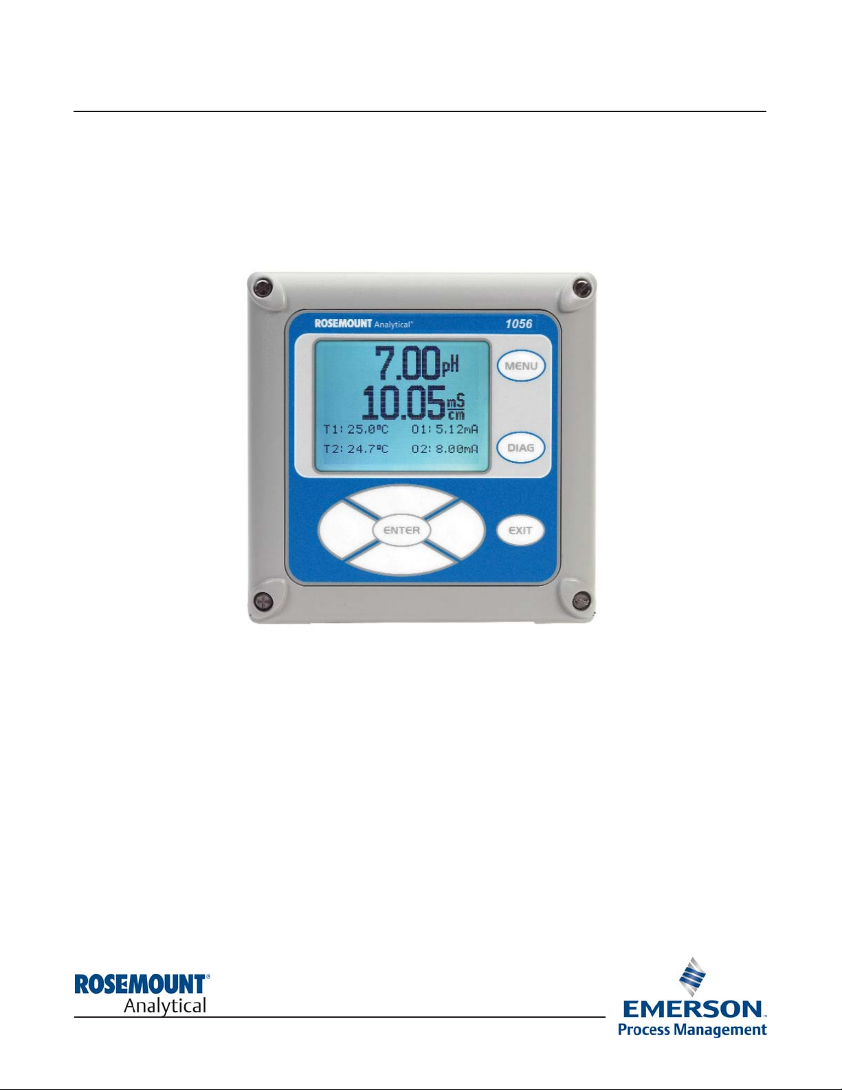
1056 PROFIBUS DP ADDENDUM
For use with the 1056 units installed with Communications option –DP (1056-0X-2X-3X-DP)
Instruction Manual Addendum
PN 51-1056DP/rev.D
March 2012
1056
Page 2
ESSENTIAL INSTRUCTIONS
READ THIS PAGE BEFORE PROCEEDING!
Your instrument purchase from Rosemount
Analytical, Inc. is one of the finest available for your
particular application. These instruments have been
designed, and tested to meet many national and
international standards. Experience indicates that its
performance is directly related to the quality of the
installation and knowledge of the user in operating
and maintaining the instrument. To ensure their continued operation to the design specifications, personnel should read this manual thoroughly before
proceeding with installation, commissioning, operation, and maintenance of this instrument. If this
equipment is used in a manner not specified by the
manufacturer, the protection provided by it against
hazards may be impaired.
• Failure to follow the proper instructions may
cause any one of the following situations to
occur: Loss of life; personal injury; property damage; damage to this instrument; and warranty
invalidation.
• Ensure that you have received the correct model
and options from your purchase order. Verify that
this manual covers your model and options. If
not, call 1-800-854-8257 or 949-757-8500 to
request correct manual.
• For clarification of instructions, contact your
Rosemount representative.
• Follow all warnings, cautions, and instructions
marked on and supplied with the product.
• Use only qualified personnel to install, operate,
update, program and maintain the product.
• Educate your personnel in the proper installation,
operation, and maintenance of the product.
• Install equipment as specified in the Installation
section of this manual. Follow appropriate local
and national codes. Only connect the product to
electrical and pressure sources specified in this
manual.
• Use only factory documented components for
repair. Tampering or unauthorized substitution of
parts and procedures can affect the performance
and cause unsafe operation of your process.
• All equipment doors must be closed and protective covers must be in place unless qualified personnel are performing maintenance.
Equipment protected throughout by double insulation.
• Installation and servicing of this product may expose personel
to dangerous voltages.
• Main power wired to separate power source must be
disconnected before servicing.
• Do not operate or energize instrument with case open!
• Signal wiring connected in this box must be rated at least
240 V.
• Non-metallic cable strain reliefs do not provide grounding
between conduit connections! Use grounding type bushings
and jumper wires.
• Unused cable conduit entries must be securely sealed by
non-flammable closures to provide enclosure integrity in
compliance with personal safety and environmental protection
requirements. Unused conduit openings must be sealed with
NEMA 4X or IP65 conduit plugs to maintain the ingress
protection rating (NEMA 4X).
• Electrical installation must be in accordance with the National
Electrical Code (ANSI/NFPA-70) and/or any other applicable
national or local codes.
• Operate only with front panel fastened and in place.
• Proper use and configuration is the responsibility of the
user.
This product generates, uses, and can radiate radio frequency
energy and thus can cause radio communication interference.
Improper installation, or operation, may increase such interference. As temporarily permitted by regulation, this unit has not
been tested for compliance within the limits of Class A computing devices, pursuant to Subpart J of Part 15, of FCC Rules,
which are designed to provide reasonable protection against
such interference. Operation of this equipment in a residential
area may cause interference, in which case the user at his own
expense, will be required to take whatever measures may be
required to correct the interference.
This product is not intended for use in the light industrial,
residential or commercial environments per the instrument’s certification to EN50081-2.
Emerson Process Management
2400 Barranca Parkway
Irvine, CA 92606 USA
Tel: (949) 757-8500
Fax: (949) 474-7250
http://www.rosemountanalytical.com
© Rosemount Analytical Inc. 2012
WARNING
RISK OF ELECTRICAL SHOCK
CAUTION
CAUTION
Page 3
QUICK START GUIDE
Profibus
1. Refer to Model 1056 Instruction Manual, PN 51-1056 for installation instructions.
2. Ensure that the M12 interconnect cable is installed. See Section 3.0 for wiring instructions. Make, output, and
power connections.
3. Once connections are secured and verified, apply power to the analyzer.
4. When the analyzer is powered up for the first time, Quick Start screens appear. Quick Start operating tips
are as follows:
a. A backlit field shows the position of the cursor.
b. To move the cursor left or right, use the keys to the left or right of the ENTER key. To scroll up or down or
to increase or decrease the value of a digit use the keys above and below the ENTER key. Use the left or
right keys to move the decimal point.
c. Press ENTER to store a setting. Press EXIT to leave without storing changes. Pressing EXIT during
Quick Start returns the display to the initial start-up screen (select language).
5. Complete the steps as shown in the Quick Start Guide flow diagram, Fig. A in the Model 1056 manual. All
Profibus configured Model 1056 units include an additional step 5 during Quick Start (step 4 if AC line power
does not appear):
1. Choose local language
2. Choose Measurement option
3. Choose Temperature units
4. AC line Power frequency (if applicable)
5. Profibus Address
The Quick Start screen in step 5 appears as below:
Enter a numeric Profibus network address from 000-125 for the Model 1056 Profibus device to be commissioned.
6. After the last step, the main display appears. The outputs are assigned to default values.
7. To change output, and temperature-related settings, go to the main menu and choose Program. Follow the
prompts. For a general guide to the Program menu, see the Quick Reference Guide, Fig. B in the Model
1056 manual.
8. To return the analyzer to the default settings, choose Reset Analyzer under the Program menu.
Quick Start
Profibus Address
126
Electrical installation must be in accordance with the National Electrical Code
(ANSI/NFPA-70) and/or any other applicable national or local codes.
WARNING
RISK OF ELECTRICAL SHOCK
Page 4

This manual contains instructions for installation and operation of the Model 1056 Dual-Input Intelligent
Analyzer with Profibus DP digital communications. The following list provides notes concerning all
revisions of this document.
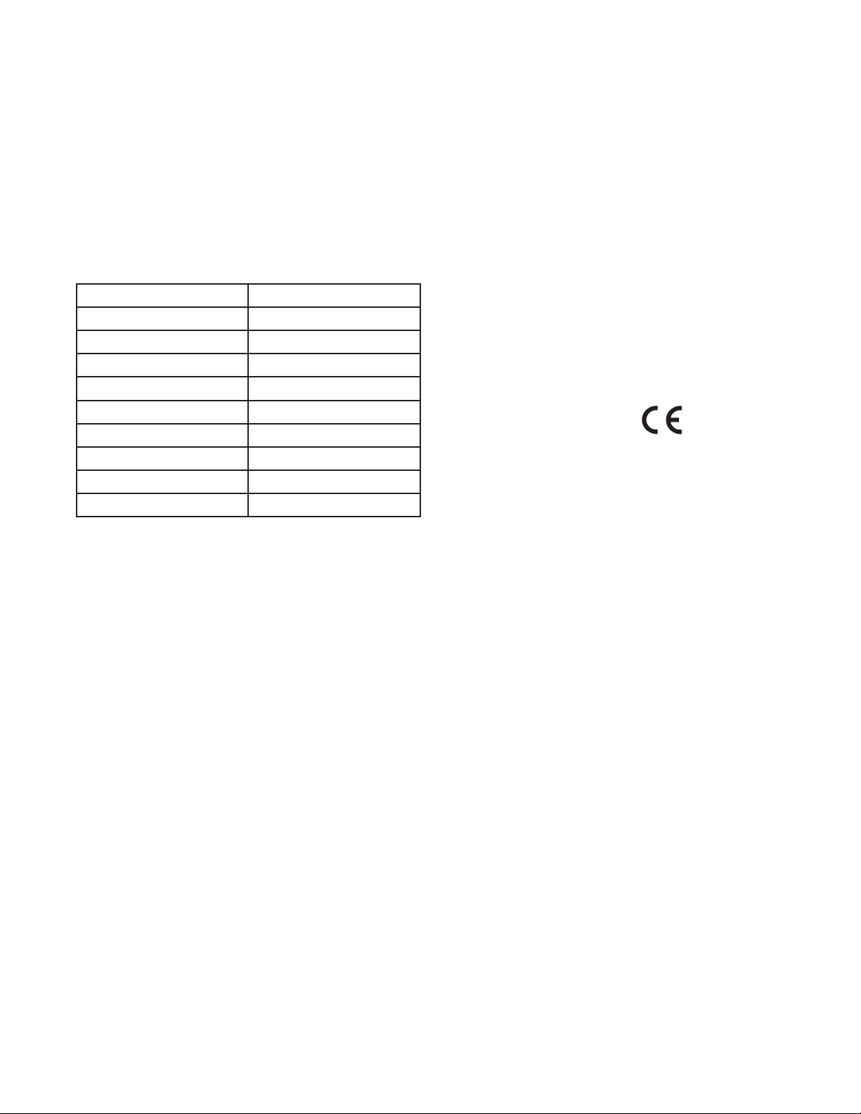
Rev. Level Date Notes
A 1/08 This is the initial release of the product manual. The manual has been reformatted to reflect the
Emerson documentation style and updated to reflect any changes in the product offering and is an
Addendum to the Model 1056 manual.
B 9/08 FM and CSA agency approval, Class 1, Div 2.
C 3/12 Update addresses - mail and website
About This Document
Page 5

i
MODEL 1056DP TABLE OF CONTENTS
1056 Profibus DP
Instruction Manual Addendum
For use with the 1056 units installed with –DP Communications ordering option 1056-0X-2X-3X-DP
TABLE OF CONTENTS
QUICK START GUIDE
QUICK REFERENCE GUIDE
TABLE OF CONTENTS
Section Title Page
1.0 DESCRIPTIONS AND SPECIFICATIONS ............................................................. 1
1.1 General Specifications ............................................................................................. 1
1.2 Mechanical and Wiring Specifications...................................................................... 1
1.3 Environmental Specifications................................................................................... 1
1.4 Approvals ................................................................................................................. 1
1.5 Other Specifications................................................................................................. 1
2.0 INTRODUCTION TO PROFIBUS ADAPTOR AND PROFIBUS NETWORKS ....... 2
2.1 Introduction to Model 1056 with PROFIBUS ........................................................... 2
2.2 Overview of PROFIBUS-DP .................................................................................... 2
2.3 Introduction to PROFIBUS - General ...................................................................... 3
3.0 INSTALLATION AND WIRING ............................................................................... 5
3.1 Profibus Board ........................................................................................................ 5
3.2 Wiring Directly to Profibus Network ......................................................................... 6
3.3 Wiring to a Profibus Network with an M12 adapter cable assembly ....................... 8
4.0 PROGRAMMING PROFIBUS ................................................................................. 11
4.1 Changing Profibus Address at the Device .............................................................. 11
5.0 DEVICE CONNECTION TO PROFIBUS NETWORK ............................................. 12
5.1 Communications Architecture - Overview................................................................ 12
5.2 Data Transmission .................................................................................................. 12
5.3 Device Database File (GSD file) .............................................................................. 13
6.0 PROFIBUS ACCESSORIES ................................................................................... 15
6.1 Profibus network accessories ................................................................................. 15
6.2 Model 1056 Profibus accessories ............................................................................ 15
6.3 Spare Parts Table..................................................................................................... 16
7.0 PROFIBUS TROUBLESHOOTING ........................................................................ 17
7.1 Profibus Diagnostics ................................................................................................ 17
7.2 Profibus Faults and Warnings ................................................................................. 18
7.3 Troubleshooting Profibus Faults and Warnings ...................................................... 19
Page 6

THIS PAGE LEFT BLANK INTENTIONALLY
ii
Page 7
1.1 GENERAL SPECIFICATIONS
1.1.1 Profibus Slave (Station_Type =0)
Pure DP Device (FMS_supp =0)
1.1.2 Ten Baud Rates Supported:
1.1.3 Adding slave address via Profibus DP Enabled
(Set_Slave_Add_Supp =1)
Automatic transmission rate recognition supported
(Auto_Baud_supp =1)
Modular device (Modular_Station =1)
Max number of modules (Max_Module =29)
1.2 MECHANICAL AND WIRING
SPECIFICATIONS
The Profibus DP-V1 communciations board mounts in
the digital communications card slot inside the Model
1056 (nearest the power supply board). A 10-lead
flat ribbon cable connects the Profibus communciations board to the mating connector labeled “DIG I/O”
on the main board .
Interfacing to a Profibus DP network is made by connecting the 4-post connector on the left side of the
Profibus board to the Profibus cable.
The Profibus board ships with a mating 4-position
removable terminal block header.
Alternatively, Profibus-configured Model 1056 units
can be wired to a Profibus network using an M12
adaptor cable assembly. The M12 adaptor cable
assembly offered by Rosemount Analytical is an
ordering option and is not provided with the Model
1056-DP unit.
The Profibus board provides isolated 5V for terminator power at the interface to the Profibus network.
1.3 ENVIRONMENTAL SPECIFICATION –
1056 INSTRUMENT WITH PROFIBUS
DP CARD
• Ambient Temperature: 0 to 55 deg C
• Relative Humidity: 5 to 95 % (non condensing)
• Storage Temperature: -20 to 60 deg C
1.4 APPROVALS – 1056 INSTRUMENT
WITH PROFIBUS DP BOARD
(Models: 1056-0X-2X-3X-DP)
1.5 OTHER SPECIFICATIONS
1. Profibus board is detected by sensing resistance of
4.99k +/- 3% on DIG I/O connector between pins 8
and 1 (pin 8 to GND). Profibus is NOT present when
resistance is outside specified range.
2. Station address provided by mainboard and pre-
served in NV memory during power down.
a. Station address may be remotely re-configured
by a Bus Master device on the network.
b. Station address is pre-set to 126 at the factory
(out of box default).
c. Profibus card uses station address 23 decimal
if it is powered without an attached main board
connection.
3. The Profibus board will operate continuously in an
ambient temperature environment between 0C and
+55C.
4. Profibus certification: The product is certified as a
Profibus DP V0 and V1 Slave device.
SECTION 1.0
DESCRIPTION AND SPECIFICATIONS
1
MODEL 1056DP SECTION 1.0
DESCRIPTION AND SPECIFICATIONS
9.6 kbps (9.6_supp =1)
19.2 kbps (19.2_supp =1)
45.45 kbps (45.45_supp =1)
93.75 kbps (93.75_supp =1)
187.5 kbps (187.5_supp =1)
500 kbps (500_supp =1)
1.5 Mbps (1.5M_supp =1)
3 Mbps (3M_supp =1)
6 Mbps (6M_supp =1)
12 Mbps (12M_supp =1)
RFI/EMI: EN-61326
LVD: EN-61010-1
Page 8

MODEL 1056DP SECTION 2.0
INTRODUCTION
This page left blank intentionally
2
Page 9
3
SECTION 2.0
INTRODUCTION TO PROFIBUS ADAPTOR AND
PROFIBUS NETWORKS
MODEL 1056DP SECTION 2.0
INTRODUCTION
2.1 INTRODUCTION TO MODEL 1056 WITH PROFIBUS
2.2 OVERVIEW OF PROFIBUS-DP
2.3 INTRODUCTION TO PROFIBUS - GENERAL
2.1 INTRODUCTION TO MODEL 1056 WITH PROFIBUS
Profibus configurations of Model 1056 (1056-0X-2X-3X-DP) allow digital communications with a Profibus class 1
master to read measured process variables.
Profibus configured Model 1056 units support communications with a Profibus master using any combination of
dual measurement inputs.
Profibus configured Model 1056 units include the following basic components:
1. A plug-in communications board in the card cage slot nearest the Power Supply
2. An M12 cable assembly and metal fitting for connection to the Profibus network (optional)
3. An IPL (Initial program load) for the 1056 main board to add Profibus functionality
4. RAII1056.GSD file for use with a Class 1 master. Must be downloaded from Rosemount Analytical web
address: http://www.emersonprocess.com/raihome/liquid/products/AMS_FIELDBUS.asp
2.2 OVERVIEW OF PROFIBUS-DP
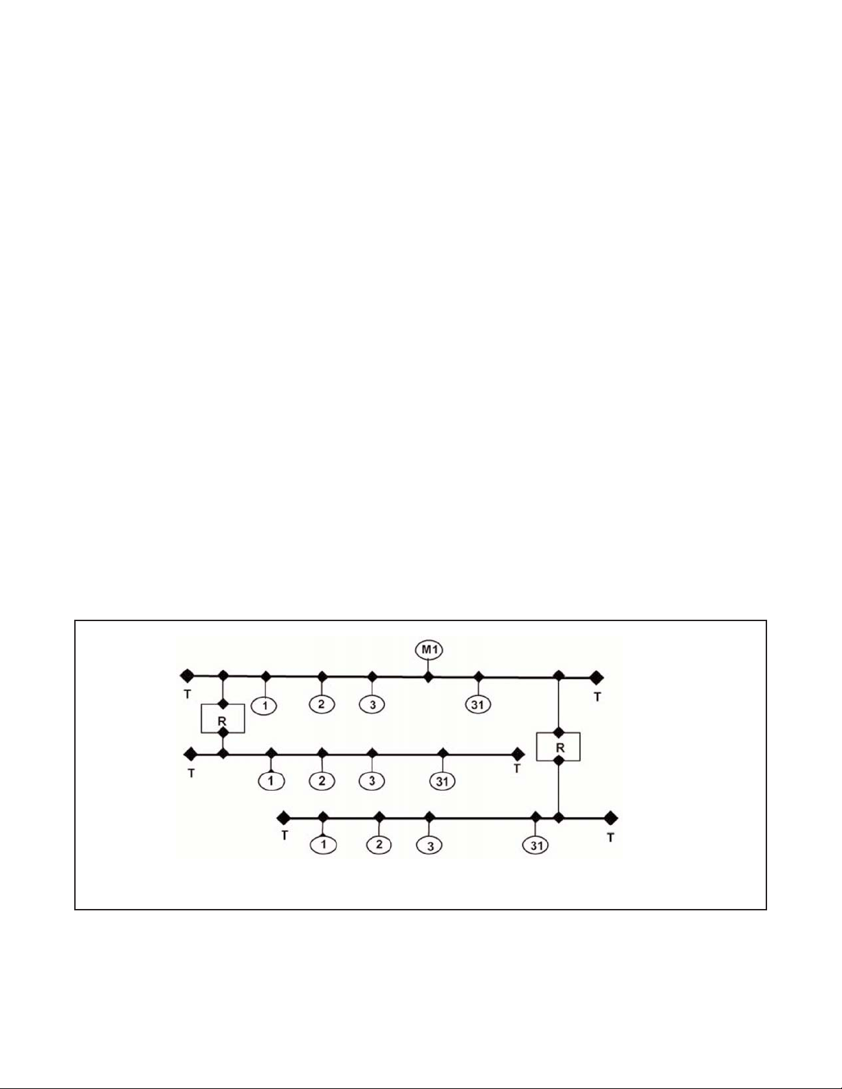
Fieldbus networks are serial communication systems (see Figure 1) used to pass data signals between host
systems and distributed peripheral equipment. The principal advantages of such a system are reduced cabling,
commissioning and maintenance costs when compared with conventional architectures. A pair of wires is all that
is required to transmit all the necessary signals (inputs, outputs, settings, diagnostics, etc.).
Fig 1. PROFIBUS-DP Tree Topology
Note:
T: Termination
R: Repeater (line amp)
Page 10

4
2.3 INTRODUCTION TO PROFIBUS - GENERAL
Profibus is an open FIELDBUS standard complying with the harmonized European standard EN 50170. It permits
devices from different manufacturers to communicate with one another without the need for specialized interfaces.
It may be used equally well for high speed, time critical data transmission or for transfers of large quantities of
complex data signals.
Profibus exists in three versions or protocol architectures.
• PROFIBUS-DP (Decentralized Periphery), is designed for communications
between automation systems and distributed input/output (I/O) devices. It may be
used to replace 24V or 0-20mA parallel transmission systems.
• PROFIBUS-PA (Process Automation) is designed to meet the specific needs of
process engineering industries for use in explosion-proof and potentially explosive
areas. Sensors and actuators are connected together on the same bus, including
in dangerous within hazardous intrinsically safe zones. Both the signal data and
the power signals travel over a two-wire link in compliance with International
standard, IEC 1158-2.
• PROFIBUS-FMS (Fieldbus Message Specification) is primarily intended for cell
management. Its sophisticated functions allow it to cover a wide range of
applications. It may be used for both complex and high volume data exchanges.
MODEL 1056DP SECTION 2.0
INTRODUCTION
Page 11

5
SECTION 3.0
INSTALLATION AND WIRING
3.1 PROFIBUS BOARD
3.2 WIRING DIRECTLY TO A PROFIBUS NETWORK
3.3 WIRING TO A PROFIBUS NETWORK WITH AN M12 CABLE ASSEMBLY
MODEL 1056DP SECTION 3.0
INSTALLATION AND WIRING
This section outlines recommended methods of wiring Model 1056 units which include a Profibus DP digital communications board. The conventional method is to wire a standard purple Profibus cable directly to the instrument. Alternatively, Profibus-configured Model 1056 units can be wired to a Profibus network using an M12 adaptor cable assembly. The M12 adaptor cable assembly offered by Rosemount Analytical is an ordering option and
is not provided with the Model 1056-DP unit. See Sec. 6.0 Profibus Accessories for parts ordering information.
Additional accessories are also available to support necessary connections to a Profibus network and Profibus
master.
3.1 PROFIBUS BOARD
Profibus-configured Model 1056 units (Model number 1056-0X-2X-3X-DP) include a pre-installed Profibus communications board and a ribbon cable. A 4-lead removable terminal block is installed on the Profibus board to allow
wiring to a Profibus network.
Profibus-configured Model 1056 units also include a pre-installed 10-lead ribbon cable that interfaces the communications board to the main PCB. Upon initial start-up, the Profibus communications board will be recognized by
the main PCB microprocessor.
Profibus communications board – Profibus cable connection side
Profibus communications board – ribbon cable connection side
Page 12
6
2. Secure the purple Profibus cable with a cable
gland fittings and nut from the outside of the enclosure to ensure a proper seal. Note that the cable
gland fittings (PN 23554-00 - Cable Gland Kit,
Quantity 5) does not require the securing nut inside
the enclosure to properly install the fitting. Simply
thread the fitting into the grounding plate inside the
enclosure and tighten.
Once the gland fitting is tightly screwed into the
enclosure and internal grounding plate, only the
external nut needs to be tightened to properly seal
the Profibus cable.
MODEL 1056DP SECTION 3.0
INSTALLATION AND WIRING
3.2 Wiring Directly To A Profibus Network
To connect a Profibus-configured Model 1056 to a Profibus network, the conventional method is to wire a stan-
dard purple Profibus cable directly to the Profibus board inside the instrument. The Profibus board is designed
to accommodate direct wiring of a Profibus cable to a removable 4-lead terminal block on the Profibus board.
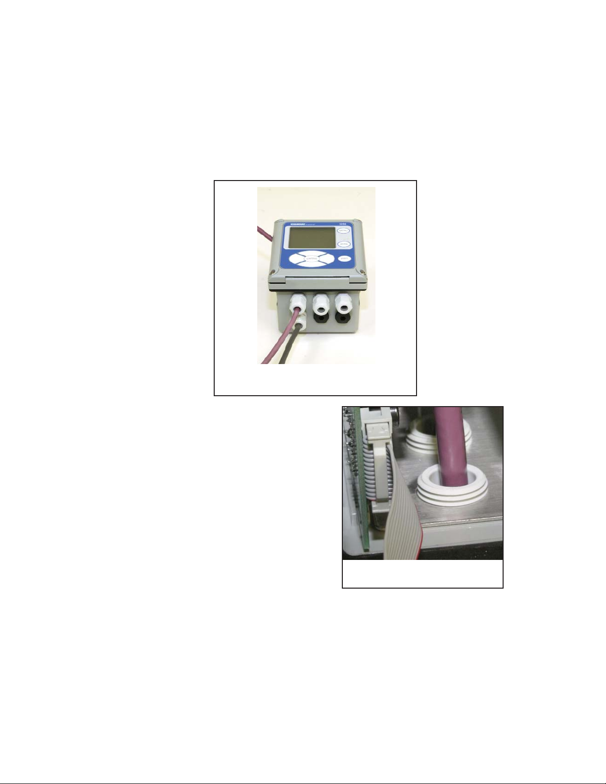
1. Feed the purple Profibus cable through a cable gland fitting. Install the cable gland fitting into the enclosure
opening on the leftmost side of the enclosure nearest the front of the door hinge. See photo. Note that the
power cable should be installed in the leftmost side of the enclosure farthest from the front of the door hinge
– as shown in the photo below.
Proper enclosure opening locations for
cable installation
Cable gland fittings secured on
internal grounding plate.
Page 13

7
3. Remove the 4-lead terminal block which is installed
on the Profibus slide-in board. This photo shows
the 4-lead terminal block installed onto the board.
4. Wire the two leads of the purple Profibus cable (red
and green) to the A and B positions of the 4-lead
removable terminal block. A #0 Philips head screw
driver is required to open and close the terminal
posts on the terminal block. The lead positions are
labeled on the Profibus card (A and B) to assist in
wiring.
Note: that Profibus wiring is polarity-sensitive. The
Green color lead must be wired to lead position A.
The Red color lead must be wired to lead position B.
Caution: Make sure the Profibus cable is properly
prepared. Unshielded wire leads can lead to poor
signal integrity from the Profibus device to the Master
5. After wiring the Profibus cable to the terminal block,
slide the wired 4-lead terminal block onto the 4 pins
protruding from Profibus board on the left side.
Photo shows the 4-lead terminal block properly
wired to the Profibus board and installed onto the
board.
Note: the Profibus cable must be directed downwards. The Profibus board can be partially or fully
removed to allow easy insertion of the 4-lead terminal block onto the Profibus board.
MODEL 1056DP SECTION 3.0
INSTALLATION AND WIRING
Profibus board showing
removable 4-lead
terminal block
Wiring Profibus cable to
4-lead terminal block
Profibus cable and terminal block
installed to Profibus board
Page 14
8
6. Ensure that the 10-lead ribbon cable is properly
connected from the Profibus board to the 10-pin
shrouded connector labeled “DIG I/O” on the main
printed circuit board. Once power is wired to the
unit (as shown in photo), the Profibus-configured
Model 1056 is ready for power up and communication on a Profibus network.
3.3 WIRING TO A PROFIBUS NETWORK WITH AN M12 ADAPTOR CABLE ASSEMBLY
Alternatively, Profibus-configured Model 1056 can be wired to a Profibus network using an M12 adaptor cable
assembly. The adaptor assembly kit accessory offered by Rosemount Analytical is designed to connect to a standard Profibus network T-cable which is directly connected to the Profibus network.
The M12 cable adaptor assembly is an ordering option. The kit is not provided with the Profibus-configured Model
1056. See Sec. 6.0 Profibus Accessories for ordering information.
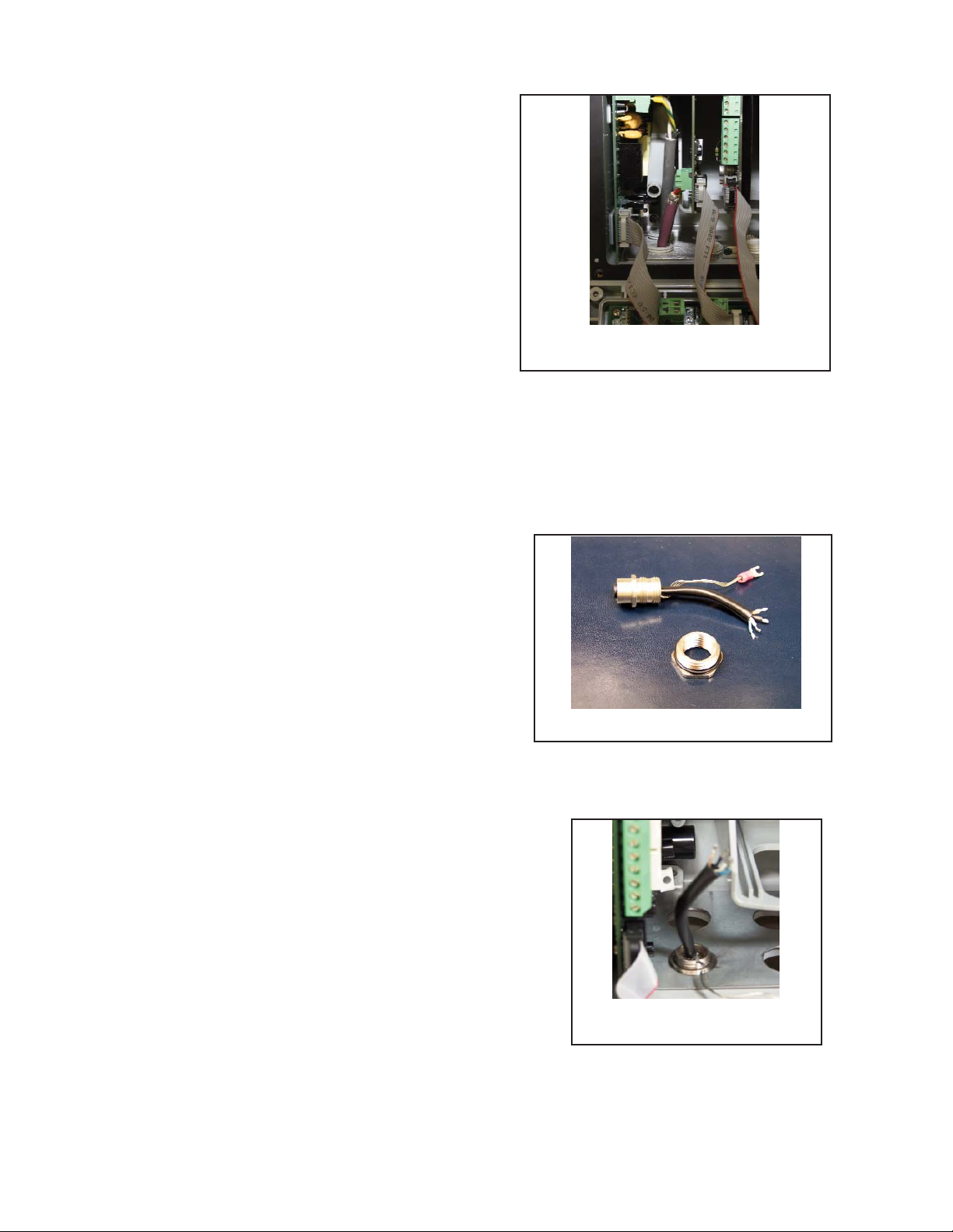
The M12 cable adaptor is an interconnect cable
between the communications board and the Profibus
network. The 5-pin female connector on the fitting end
of the M12 cable adaptor allows direct interface to a
Profibus network. The M12 cable adaptor kit includes:
a. threaded metal adaptor fitting with soldered
4-lead cable and ground wire
b. threaded metal nut and o-ring to secure metal
fitting and cable to enclosure through an opening
c. Instruction sheet
MODEL 1056DP SECTION 3.0
INSTALLATION AND WIRING
M12 cable assembly installation
1. Install the M12 cable adaptor through enclosure
opening on the leftmost side of the enclosure nearest the front of the door hinge. See photo.
M12 adaptor cable assembly
Complete Profibus board installation
with ribbon cable attached
M12 adaptor cable assembly
secured to grounding plate.
Page 15

9
MODEL 1056DP SECTION 3.0
INSTALLATION AND WIRING
2. Secure the M12 cable assembly with the metal
threaded nut from the outside of the enclosure to
ensure a proper seal.
3. Remove the 4-lead terminal block which is installed
on the Profibus slide-in board. Wire the four leads
of the cable assembly to the 4-lead removable
terminal block. The lead positions are labeled on
the Profibus board (Black, Green, Red, White) to
assist in wiring. Follow the wiring sequence
indicated on the Profibus board (see photo). A #0
Philips head screwdriver is required to open and
close the terminal posts on the provided terminal
block.
Note: that Profibus wiring is polarity-sensitive. The
Green color lead must be wired to lead position A.
The Red color lead must be wired to lead position B.
M12 cable assembly wired to 4-lead
Profibus terminal block.
Proper enclosure opening location
for M12 cable assembly fitting.
M12 cable lead positions.
WHITE
RED
GREEN
BLACK
Page 16

10
MODEL 1056DP SECTION 3.0
INSTALLATION AND WIRING
Ensure that the 10-lead ribbon cable is properly
connected from the Profibus board to the 10-pin
shrouded connector labeled “DIG I/O” on the main
printed circuit board (see photo).
5.
Connect the Model 1056 Profibus unit to a Profibus
network cable (purple) using standard Profibus
connectors and cable fittings. Once power is wired
to the unit (as shown in photo), the Profibusconfigured Model 1056 is ready for power up and
communication on a Profibus network.
Complete M12 cable
assembly installation
Profibus M12 Cable assembly
attached to Profibus network
T-cable fitting
4. Slide the wired 4-lead terminal block onto the 4 pins
protruding from Profibus board on the left side.
Note: the Profibus cable must be directed downwards. The Profibus board can be partially or fully
removed to allow easy insertion of the 4-lead terminal block onto the Profibus board.
Wired 4-lead terminal block
installed on Profibus DP board.
Page 17

11
MODEL 1056DP SECTION 4.0
PROGRAMMING PROFIBUS
SECTION 4.0
PROGRAMMING PROFIBUS
4.1 CHANGING PROFIBUS ADDRESS AT THE DEVICE
Properly wired and configured Profibus Model 1056 units can be accessed by the Profibus master after a GSD file
is downloaded to the Master. See Appendix A for details on the GSD file available from Rosemount Analytical.
The only programmable setting that may need to be changed is the default Profibus address or Profibus address
that was entered upon initial Quick Start routine.
Note that the Profibus device network address can also be changed from the master unit.
4.1 CHANGING PROFIBUS ADDRESS AT THE DEVICE
Profibus-configured Model 1056 units (Model number 1056-0X-2X-3X-DP) include a pre-installed Profibus communications board that is recognized by the main PCB.
To change the Profibus address,
1. Press MENU. Then select Program. The following
screen will appear.
S1: 1.234µS/cm 25.0ºC
S2: 12.34pH 25.0ºC
Program
Profibus
Outputs
Alarms
Measurement
2. Select Profibus. The following screen will appear.
3. Using the keypad, enter a numeric Profibus network address from 000-125 for the Model 1056 Profibus
unit already commissioned.
S1: 1.234µS/cm 25.0ºC
S2: 12.34pH 25.0ºC
Profibus
Address: 126
Page 18

This page left blank intentionally
12
MODEL 1056DP SECTION 4.0
PROGRAMMING PROFIBUS
Page 19

5.1 COMMUNICATIONS ARCHITECTURE- OVERVIEW
The PROFIBUS-DP communications profile specifies the operating characteristics of a serial fieldbus intended
for the interconnection of distributed digital devices at the field level. To achieve this, PROFIBUS designates
these devices as either masters or slaves:
• Masters, or active stations, control the transmission of data around the bus. A master may transmit messages
freely although, sometimes, it may have to obtain network access rights (in the case of multi-master applications
using tokenpassing).
• Slaves, or passive stations, are distributed devices (I/O devices, valves, instrumentation transmitters, etc.)
that do not have bus access rights without authorization. Their operation is limited to acknowledging messages
received or transmitting messages at the request of a master device. In order to route data to its destination
address, or to tell the destination address how to handle the data received, a formal set of rules and conventions
for the exchange of data signals is required.
The International Standards Organization (ISO) uses an outline model referred to as the Open Systems
Interconnection (OSI) reference model. This reference model defines 7 levels used in the transfer of data. These
levels are referred to as layers. PROFIBUS-DP operates on the two lowest levels, layer 1 (physical connections)
and layer 2 (data links). Layers 3 to 7 are unused in this profile.
5.2 DATA TRANSMISSION
PROFIBUS-DP is designed for efficient communication between programmable logic controllers (PLCs), industrial
PCs (IPCs), etc., and distributed peripheral devices such as I/O devices, drives, valves, and measurement sensors, etc. Most data exchanges are carried out in a cyclic fashion. The communication functions required are specified by the basic PROFIBUS-DP communications profile, in accordance with the European harmonized standard,
EN 50170.
5.3 DEVICE DATABASE FILE (GSD FILE)
PROFIBUS devices may be defined in terms of their performance and their available functions, e.g. the number
of I/O signals and diagnostic messages, and their bus settings, such as transmission speeds or time monitoring.
These settings will vary with the equipment type and manufacturer but they are usually defined in the manufacturer's documentation.
To simplify PROFIBUS configuration or even make it transparent to the user, this data is collected together into a
single computer file, sometimes referred to as a device data base file or, more often, a GSD file.
GSD files provide a clear and complete description of a device's properties. The Model 1056 device has its own
GSD file.
Model 1056 GSD files may be downloaded free from the GSD library on the web server at:
http://www.emersonprocess.com/raihome/liquid/products/AMS_FIELDBUS.asp
13
MODEL 1056DP SECTION 5.0
DEVICE CONNECTION TO PROFIBUS NETWORK
SECTION 5.0
DEVICE CONNECTION TO PROFIBUS NETWORK
5.1 COMMUNICATIONS ARCHITECTURE- OVERVIEW
5.2 DATA TRANSMISSION
5.3 DEVICE DATABASE FILE (GSD FILE)
Page 20

This page left blank intentionally
14
MODEL 1056DP SECTION 5.0
DEVICE CONNECTION TO PROFIBUS NETWORK
Page 21
15
MODEL 1056DP SECTION 6.0
PROFIBUS ACCESSORIES
SECTION 6.0
PROFIBUS ACCESSORIES
6.1 PROFIBUS NETWORK ACCESSORIES
6.2 MODEL 1056 PROFIBUS ACCESSORIES
6.3 SPARE PARTS TABLE
Accessories are available to support connection of Profibus devices to a Profibus network and Profibus master
unit.
6.1 PROFIBUS NETWORK ACCESSORIES.
Common Profibus network parts are available to assist with commissioning Profibus devices. The following parts
are available for purchase through Rosemount Analytical. Ordering part numbers and images of these parts are
included in this section.
• M12 T-connector
• M12 Terminating resistor
• M12 Bus cable, 2-position, 1 m
• M12 Bus cable, 2-position, 0.5 m
• M12 Bus plug connector, male, straight, 5-position, shielded
• M12 Bus plug connector, female, straight, 5- position, shielded
6.2 MODEL 1056 PROFIBUS ACCESSORIES
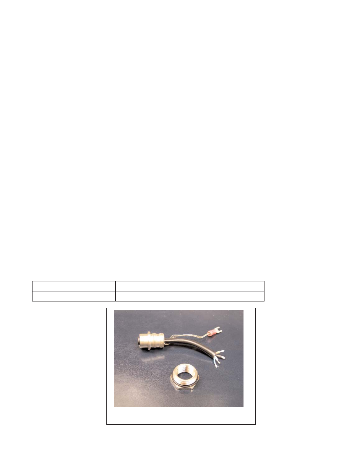
Rosemount Analytical offers an adaptor kit that allows connection of the Model 1056 Profibus instrument to a
Profibus network. This is an alternative to the conventional method of wiring a Profibus network cable directly to
the Profibus board installed in the Model 1056 Profibus instrument. The kit contents include:
a. M12 4-pin adaptor assembly including 4 soldered leads and a ground wire
b. M12 threaded adaptor nut for installing the M12 adaptor assembly into an enclosure opening of
the Model 1056 unit
c. o-ring for threaded adaptor nut to allow watertight sealing of the M12 adaptor assembly to the
enclosure of Model 1056 unit
d. instruction sheet for kit assembly and installation
Ordering information for the M12 adaptor assembly offered by Rosemount Analytical:
Part Number Description
24301-00 M12 adaptor assembly kit
Figure 6.1 M12 adaptor assembly kit
Page 22
16
MODEL 1056DP SECTION 6.0
PROFIBUS ACCESSORIES
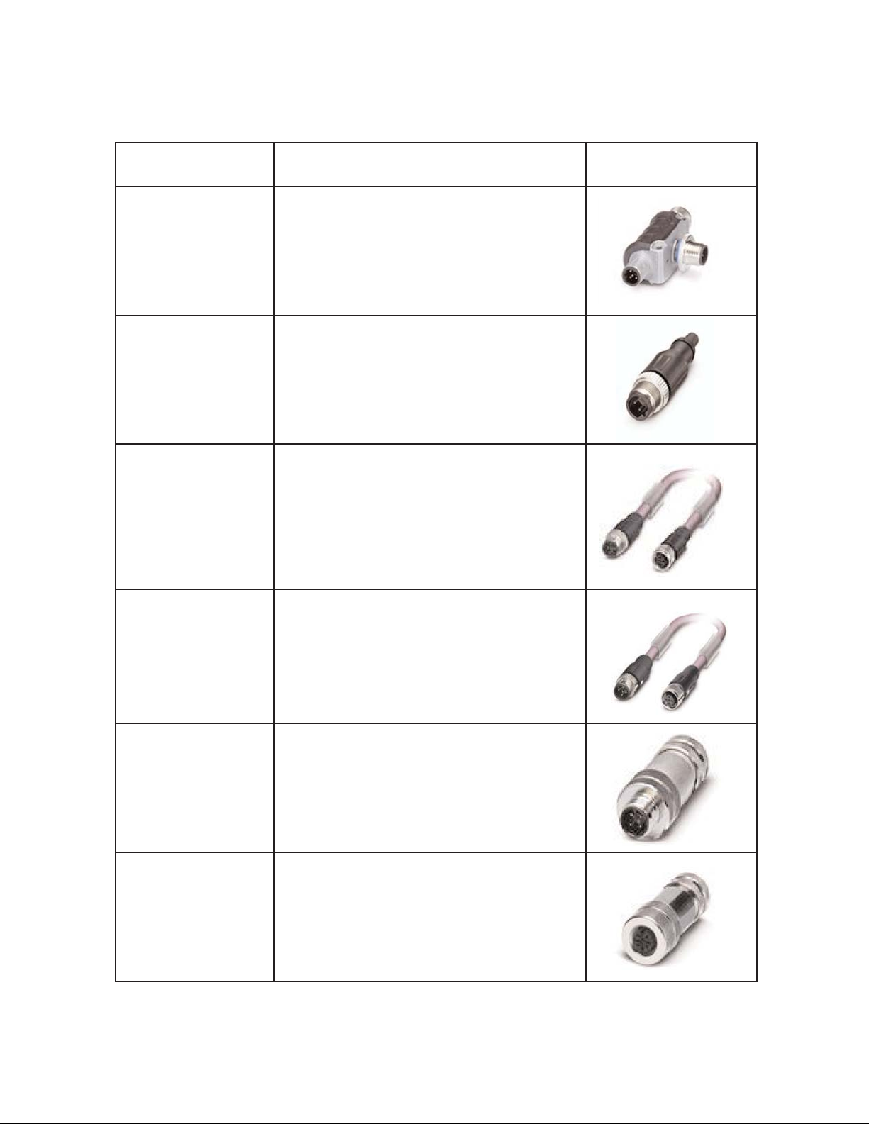
6.3 Spare parts table
Part Number Description Image
9120705 PROFIBUS M12 T-connector
9120706 PROFIBUS M12 Terminating resistor
9200344 PROFIBUS M12 Bus cable, 2-position, 1 m
9200345 PROFIBUS M12 Bus cable, 2-position, 0.5 m
9120707 PROFIBUS M12 Bus plug connector, male,
straight, 5-position, shielded
9120708 PROFIBUS M12, Bus plug connector, female,
straight, 5- position, shielded
Profibus network accessories
Figure 6.2 Profibus network accessories.
Page 23

17
MODEL 1056DP SECTION 7.0
PROFIBUS DIAGNOSTICS, FAULTS, WARNINGS
SECTION 7.0
PROFIBUS DIAGNOSTICS, FAULTS, WARNINGS
7.1 PROFIBUS DIAGNOSTICS
7.2 PROFIBUS FAULT AND WARNINGS
7.3 TROUBLESHOOTING PROFIBUS FAULT AND WARNINGS
7.1 PROFIBUS DIAGNOSTICS
Profibus-configured Model 1056 units offer a number of useful diagnostics to assist in start up and communications troubleshooting.
To access Profibus diagnostics,
1. Press DIAG. The following screen will appear
if a Profibus-related fault or warning exists.
S1: 1.234µS/cm 25.0ºC
S2: 12.34pH 25.0ºC
Diagnostics
Faults
Warnings
Sensor 1
Sensor 2
Profibus
Out 1: 12.05 mA
Out 2: 17.08 mA
1056-01-20-30-DP
Instr SW Ver: xx.xx
Profibus Diagnostics Condition
Profi-board mismatch Profibus board is incompatible with main board.
Function limited Profibus board has new features that main board does not support
Self-test passed All power-on self-tests passed
Self-test failed Any power-on self-test failed
Master detected At least 1 Profibus message received
Master not detected No Profibus message has been received
Cable open or short Cable is detected as open or shorted
Wires A & B reversed Cable is detected as reversed
Cable good Cable is detected as properly connected
Board SW Ver: 1.01 Information only: Indicates software version of Profibus board
Address: 126 Information only: Indicates Profibus device address
Baud rate: 115200 Information only: Indicates Profibus communications transmission
2. Scroll down and select Profibus. Press ENTER. Based on the condition of the Profibus installation and
network connection, a number of diagnostics may appear.
The following is a list of all possible Profibus diagnostics and their requisite conditions.
Page 24

18
7.2 PROFIBUS FAULT AND WARNINGS
Profibus-related Fault and Warning conditions will be automatically detected and indicated on the Model 1056
display. The main display of the Model 1056 includes a Fault and Warning banner on the lower portion of the
display that will intermittently flash if any Fault or Warning condition exists.
Profibus-related Fault conditions are detected errors that require immediate operator intervention to correct
Profibus communication problems related to hardware, software, or network integrity.
Profibus-related Warning conditions are less critical errors or potential problems related to Profibus hardware, software, or network integrity. Operator intervention is advised to inspect and diagnose these conditions.
2. Select Fault and/or Warning. Press ENTER. Based on the condition of the Profibus installation and net
work connection, there are three Faults and three Warnings that can be generated. The following table
provides all possible Profibus Faults and Warnings and lists their conditions and probable causes.
MODEL 1056DP SECTION 7.0
PROFIBUS DIAGNOSTICS, FAULTS, WARNINGS
To locally access details about Profibus Fault and
Warning conditions,
1. Press DIAG. The following screen will appear
if a Profibus fault or warning exists.
S1: 1.234µS/cm 25.0ºC
S2: 12.34pH 25.0ºC
Diagnostics
Faults
Warnings
Sensor 1
Sensor 2
Profibus
Out 1: 12.05 mA
Out 2: 17.08 mA
1056-01-20-30-DP
Instr SW Ver: xx.xx
Displayed Text: Condition Probable Cause(s)
Fault:
Profi-board Mismatch
If Profibus card major revision is
not in the main board’s Profibus
major revisions list.
Main board software is too old.
Fault:
Profi Self-Test Fail
At least one of the internal power-
on self-tests failed.
Bad hardware component.
Fault:
Profi Internal Comm
Main board detects a Profibus card
installed, but Profibus card is not
sending messages to the main
board.
Bad hardware component.
Displayed Text: Condition Probable Cause(s)
Warning:
Profibus short/open
Detected when static potential on
Profibus B lead <= static potential
on A lead.
No Profibus cable connected or A
and B wires are shorted.
Warning:
Profibus wires A & B reversed
Detected when data activity is
present on Profibus, but data polar
ity is observed as inverted.
Profibus A and B wires are
reversed.
Warning:
Profibus function limited
If Profibus card minor revision is
greater than the main board’s
minor revision.
Main board software is too old.
Page 25

19
7.3 TROUBLESHOOTING PROFIBUS FAULT AND WARNINGS
Model 1056 provides on-screen User Help information and advice to directly assist the user in troubleshooting
Fault and/or Warning conditions.
Once the individual Fault or Warning condition is displayed, the user can access User Help for each Fault and
Warning condition.
MODEL 1056DP SECTION 7.0
PROFIBUS DIAGNOSTICS, FAULTS, WARNINGS
To access User Help for displayed individual Fault
conditions,
1. If more than one Fault condition exists, scroll to
the Fault condition of interest.
2. Press ENTER. The following table provides User
Help screens that appear for individual Fault
conditions:
User Help screens
Fault:
Profi-board Mismatch
1. Replace Profibus board.
2. Replace main board.
Fault:
Profi Self-Test Fail
1. Cycle power.
2. Replace Profibus board.
Fault:
Profi Internal Comm
1. Cycle power.
2. Replace Profibus card.
To access User Help for displayed individual Warning
conditions,
1. If more than one Warning condition exists, scroll
to the Warning condition of interest.
2. Press ENTER. The following table provides User
Help screens that appear for individual Warning
conditions:
User Help screens
Warning:
Profibus short/open
Check wiring.
Warning:
Profibus wires A & B reversed
Check wiring.
Warning:
Profibus function limited
Replace main board.
Page 26

20
NOTES:
Page 27

A Worldwide Network of Sales and Service
Emerson Process Management’s field sales offices are your source for more information on the fill line of Rosemount Analytical products. Field sales personnel will work closely with you to supply technical data and application information.
For more information, please contact your nearest Emerson Process Management sales office.
Immediate, Reliable Analytical Support
Now there’s a way to quickly get the right answers for your liquid analytical instrumentation questions: the Analytical Customer
Support Center.
Our staff of trained professionals is ready to provide the information you need. If you are placing an order, verifying delivery,
requesting application information, or just want to contact a Rosemount Analytical representative, a call to the Customer Support
Center will provide you with the right people, the right answers, right now.
The right people, the right answers, right now.
THE AMERICAS HEADQUARTERS
Emerson Process Management
Rosemount Analytical Inc.
Liquid Center of Excellence
2400 Barranca Parkway
Irvine, CA 92606
Phone: +1.949.757.8500
Toll Free: +1.800.854.8257
Fax: +1.949.474.7250
ASIA-PACIFIC
Emerson Process Management
Asia Pacific Private Ltd.
1 Pandan Crescent
Singapore 0512
Republic of Singapore
Phone: 65.777.8211
Fax: 65.777.0947
EUROPE
Emerson Process Management
Heath Place
Bognor Regis
West Sussex PO22 9SH
England
Phone: 44.1243.863121
Fax: 44.1243.845354
VISIT OUR WEBSITE AT
www.rosemountanalytical.com
GERMANY
Emerson Process Management
Process Gas Analyzer Center of
Excellence
GmbH & Co. OHG
Industriestrasse 1
63594 Hasselroth
Germany
T 49.6055.884.0
F 49.6055.884.20
LATIN AMERICA
Emerson Process Management
Rosemount Analytical
10241 West Little York, Suite
#200 Houston, TX 77040 USA
T 713.467.6000
F 713.827.3328
MIDDLE EAST AND AFRICA
Emerson Process Management
EPM Building
P. O. Box 17033
Jebe Ali Free Zone
Dubai, United Arab Emirates
T 971.4.8835235
F 971.4.8835312
Page 28

Credit Cards for U.S. Purchases Only.
The right people,
the right answers,
right now.
ON-LINE ORDERING NOW AVAILABLE ON OUR WEB SITE
http://www.rosemountanalytical.com
Emerson Process Management
Rosemount Analytical Inc.
2400 Barranca Parkway
Irvine, CA 92606 USA
Tel: (949) 757-8500
Fax: (949) 474-7250
http://www.rosemountanalytical.com
© Rosemount Analytical Inc. 2012
8
 Loading...