


EMAK pW 121c, pW 136c, pW 145c, Ip 1210S, Ip 1360S User Manual [ru]
...pW 121c pW 136c pW 14 c Ip 1210S Ip 1360S Ip 14 0S
|
|
|
|
|
|
|
|
|
|
|
|
|
|
|
|
|
|
|
|
|
|
|
|
|
|
|
|
|
|
|
|
|
MANUALE DI USo E MANUTENZIoNE |
|
|
|||
|
|
|
|
|
|
|
|
|
||||
|
|
|
|
|
|
IT |
|
|
||||
|
|
|
|
|
|
GB |
oPERAToR'S INSTRUCTIoN BooK |
|
|
|||
|
|
|
|
|
|
FR |
MANUEL D'UTILISATIoN ET D'ENTRETIEN |
|
|
|||
|
|
|
|
|
|
DE |
BEDIENUNGSANLEITUNG |
|
|
|||
|
|
|
|
|
|
ES |
MANUAL DE ISTRUCCIoNES |
|
|
|||
|
|
|
|
|
|
NL |
GEBRUIKSAANWIjZING |
|
|
|||
|
|
|
|
|
|
PT |
MANUAL DE INSTRUÇÕES |
|
|
|||
|
|
|
|
|
|
EL |
|
|
|
|
|
|
|
|
|
|
|
|
CZ |
NÁVOD NA POUŽITÍ A ÚDRŽBU |
|
|
|||
|
|
|
|
|
|
SK |
NÁVOD NA POUŽITIE A ÚDRŽBU |
|
|
|||
|
|
|
|
|
|
PL |
PODRĘCZNIK UŻYTKOWANIA I KONSERWACJI |
|
|
|||
|
|
|
|
|
|
RU |
hErJDJlCnDJ gJ rCgkEfnfwBB B nT{J<CkE:BDfYB? |
|
|
|||
|
|
|
|
|
|
|
|
|
|
|
|
|
|
|
|
|
|
|
|
|
|
|
|
|
|
|
|
|
|
|
|
|
|
|
|
|
|
|
|
|
|
|
|
|
|
|
|
|
|
|
|
|
|
|
|
|
|
|
|
|
|
|
|
|
|
|
|
|
|
|
|
|
|
|
|
|
|
|
|
|
|
|
|
|
|
|
|
|
|
|
|
|
|
|
|
|
|
|
|
|
|
|
|
|
|
|
|
|
|
|
|
|
|
|
|
|
3
4 |
|
|
|
|
|
|
|
|
|
|
|
|
10 |
|||||||
|
|
|
|
|
|
|||||||||||||||
|
|
|
|
|
4 |
|||||||||||||||
|
|
|
||||||||||||||||||
|
|
|
|
|||||||||||||||||
5 |
|
|
|
|
|
|
|
|
5 |
|||||||||||
|
|
|||||||||||||||||||
|
|
|
|
|
|
|||||||||||||||
6 |
|
|
|
|
|
|
|
|
|
|
|
|
|
|
|
|
|
|
|
|
|
|
|
|
|
|
|
|
|
|
|
|
|
|
|
|
|
|
|
|
|
2 |
|
|
|
|
|
|
|
|
|
|
|
|
|
|
|
|
|
|
|
|
7 |
|
|
|
|
|
|
|
|
|
|
|
|
|
|
|
|
|
|
|
|
|
|
|
|
|
|
|
|
|
|
|
|
|
|
|
|
|
|
|
|
|
8 |
|
|
|
|
|
|
|
|
|
|
|
|
|
|
|
|
|
12 |
||
|
|
|
|
|
|
|
|
|
|
|
|
|
|
|
|
|
||||
|
|
|
|
|
|
|
|
|
|
|
|
|
||||||||
9 |
|
|
|
|
|
|
|
|
|
|
|
1 |
||||||||
|
|
|
|
|
||||||||||||||||
|
|
|
|
|
13 |
|||||||||||||||
|
|
|
|
|
|
|
|
|
||||||||||||
14 |
|
|
|
|
11 |
|
27 |
17 |
18 |
||||||||
|
|
|
|
|
|
|
|
|
|
|
|
|
|
|
|||
|
|
|
|
|
|
|
|
|
|
|
|
|
|
|
|||
|
|
|
|
|
28 |
|
|
|
|
|
|
|
|
||||
|
|
|
|
|
|
|
|
|
|
|
|
|
|
|
|
||
|
|
|
|
|
11 |
|
|
|
|
|
|
|
|
22 |
|||
|
|
|
|
|
|
|
|
|
|
|
|
|
|
|
|
||
|
|
|
|
|
|
|
|
|
|
|
|
|
|
|
|
||
|
|
|
|
|
|
|
|
|
|
|
|
|
|
19 |
|||
|
|
|
|
|
|
|
|
|
|
|
|
|
|
||||
|
|
|
|
|
|
|
|
|
|
|
|
|
|
|
|
|
L |
|
|
|
|
|
|
|
|
|
|
|
|
|
|
|
|
|
|
|
|
|
|
23 |
|
|
|
|
|
|
|
|
|
20 |
|||
|
|
|
|
|
|
|
|
|
|
|
|
|
|||||
|
|
|
|
|
|
|
|
|
|
|
|||||||
|
|
|
24 |
|
|
|
|
|
|
|
|
|
21 |
||||
|
|
|
|
|
|
|
|
|
|
|
|
||||||
|
|
|
|
|
|
|
|
|
|
|
|
|
|
|
|||
1

|
A |
|
|
2 |
|
D |
2 |
1 |
|
|
|
|
|
F |
C |
E |
|
|
1 |
|
2 |
|
|
|
|
G |
|
3 |
|
|
4 |
M |
N |
|
5 |
|
b |
|
2 |
|
1 |
|
a |
|
6 |

|
IT |
Sommario |
||
|
|
|||
1 |
Informazioni Generali______________________8 |
7 |
Pulizia e Manutenzione_____________________15 |
|
2 Caratteristiche e Dati Tecnici______________9 |
8 Demolizione e Smaltimento________________16 |
|||
3 |
Disimballaggio______________________________10 |
9 |
Inconvenienti, Cause e Rimedi______________16 |
|
4 |
Installazione________________________________11 |
|
Dichiarazione CE di Conformità__________116 |
|
5 |
Funzionamento_ _____________________________12 |
|
Certificato di Garanzia____________________121 |
|
6 |
Arresto e Messaa Riposo____________________14 |
|
|
|
GB |
|
Summary |
||
1 |
General Information_______________________17 |
6 Switching Offand Storage_________________23 |
||
2 |
Features and Technical Specifications_ __18 |
7 Cleaning and Maintenance_________________24 |
||
3 |
Removing The Appliance From Its |
|
8 Dismantling And Disposal___________________25 |
|
|
Packing Materials___________________________19 |
9 Problems, Causes And Solutions_ __________25 |
||
4 |
Installation_________________________________20 |
EC Declaration of Conformity___________117 |
||
5 |
Operation____________________________________21 |
Warranty Certificate_____________________121 |
||
FR |
|
Sommaire |
|||
|
|
|
|||
1 |
Informations Generales____________________26 |
6 |
Arret et Mise au Repos_ _____________________32 |
||
2 |
Caracteristiques et Donnees |
|
7 Nettoyage et Entretien____________________33 |
||
|
Techniques___________________________________27 |
8 |
Demolition et Elimination_ ________________33 |
||
3 |
Deballage____________________________________28 |
9 |
Problemes, Causes et Solutions____________34 |
||
4 |
Installation_________________________________29 |
|
Déclaration CE de Conformité___________117 |
||
5 |
Fonctionnement_____________________________30 |
|
Certificat De Garantie_____________________122 |
||
DE |
Inhaltsverzeichnis |
|||
1 |
Allgemeine Hinweise________________________35 |
6 |
Ausschalten und Ruhestellung___________41 |
|
2 |
Technische Eigenschaften Und |
7 |
Reinigung und Wartung_____________________42 |
|
|
Technische Daten____________________________36 |
8 |
Verschrottung und Entsorgung_ _________42 |
|
3 |
Das Auspacken________________________________37 |
9 |
Betriebsstörungen, Ursachen und Abhilfe43 |
|
4 |
Installation_________________________________38 |
|
EG-Konformitätserklärung______________117 |
|
5 |
Betrieb________________________________________39 |
|
Garantie-zertificat________________________122 |
|
ES |
Sumario |
||
|
|
||
1 Información General_______________________44 |
7 Limpiezay Mantenimiento__________________51 |
||
2 Características y Datos Técnicos_________45 |
8 Demolición y Eliminación_ _________________51 |
||
3 |
Desembalaje_________________________________46 |
9 Inconvenientes, Causas y Remedios________52 |
|
4 |
Instalación__________________________________47 |
CE Declaración de Conformidad_________118 |
|
5 |
Funcionamiento_ ____________________________48 |
Certificado de Garantía___________________123 |
|
6 |
Paraday Puestaa Reposo____________________50 |
|
|
NL |
Inhoudsopgave |
||||
|
|
||||
1 |
Algemene Informatie_______________________53 |
7 |
Reiniging en Onderhoud_ ___________________60 |
||
2 Kenmerken en Technische Gegevens______54 |
8 Sloop en Verwerking________________________60 |
||||
3 Uitpakken____________________________________55 |
9 Ongemakken, Oorzaken En Oplossingen__61 |
||||
4 |
Installatie___________________________________56 |
|
EG Conformiteitverklaring______________118 |
||
5 |
Werking______________________________________57 |
|
Garantiebewijs_____________________________123 |
||
6 |
Stilstand en Opslag_ ________________________59 |
|
|
|
|
|
|
|
|
|
|
|
|
|
|
|
|

PT |
Sommario |
|||
|
|
|||
1 |
Informações Gerais_________________________62 |
7 |
Limpeza e Manutenção______________________69 |
|
2 Características e Dados Técnicos_________63 |
8 Sucateamento e Despejo____________________70 |
|||
3 Desembalagem_______________________________64 |
9 Inconvenientes, Causas E Soluções _______70 |
|||
4 |
Instalação_ __________________________________65 |
|
Declaração CE de Conformidade_________118 |
|
5 |
Funcionamento______________________________66 |
|
Certificado De Garantia___________________124 |
|
6 Parada e Colocação em Repouso___________68 |
|
|
||
EL |
|
|||
1 _______________________71 |
7 |
________________78 |
||
2 _____72 |
8 |
|
||
3 ____________________________73 |
|
_________________79 |
||
4 |
_________________________________74 |
9 |
, _____________79 |
|
5 |
____________________________________75 |
|
_______________________119 |
|
6 _______________77 |
|
ΠΙΣΤΟΠΟΙΗΤΙΚΟ ΕΓΓΥΗΣΗΣ_____________________ 124 |
||
CZ |
Obsah |
||
|
|
||
1 |
Všeobecné informace_______________________80 |
7 Čištěníaúdržba______________________________86 |
|
2 Charakteristikaa technické údaje_______81 |
8 Likvidace a zpracování_____________________87 |
||
3 |
Vybalení______________________________________82 |
9 Poruchy, příŜinyajejich odstranění______88 |
|
4 |
Instalace_____________________________________83 |
ES Prohlášení o shodě______________________119 |
|
5 |
Provoz________________________________________84 |
ZáruŜní list_________________________________125 |
|
6 Zastaveníaodstavení zařízení_____________86 |
|
||
SK |
obsah |
||
1 |
Všeobecné informácie_ _____________________89 |
7 Čistenieaúdržba____________________________96 |
|
2 Charakteristikaa technické údaje_______90 |
8 Likvidáciaa spracovanie___________________96 |
||
3 |
Odbalenie____________________________________91 |
9 Poruchy, príŜinyaich odstránenie________97 |
|
4 |
Inštalácia_ ___________________________________92 |
Prehlásenie CE o Zhode____________________119 |
|
5 Činnosť_______________________________________93 |
ZáruŜný list________________________________125 |
||
6 Zastavenie a odstavenie zariadenia_______95 |
|
||
PL |
|
Podsumowanie |
|||
|
|
|
|||
1 |
Informacje ogólne_________________________98 |
7 |
Czyszczenie i konserwacja________________105 |
||
2 |
Charekterystyki i dane techniczne______99 |
8 |
Złomowanie i utylizacja_ _________________105 |
||
3 |
Odpakowywanie____________________________100 |
9 |
Niedogodności, przyczyny, środki |
||
4 |
Instalacja __________________________________101 |
|
naprawcze___________________________________106 |
||
5 |
Funkcjonowanie____________________________102 |
|
Certyfikat zgodności CE_ _________________120 |
||
6 |
Zatrzymanie i przestawienie w |
|
|
KARTA GWARANCYJNA________________________126 |
|
|
spoczynek___________________________________104 |
|
|
||
RU |
Cjlth;fybt |
|||
1 J<obt Cdtltybz____________________________107 |
7 |
Jxbcnrf b Nt[j<cke;bdfybt |
||
2 {fhfrnthbcnbrb b Nt[ybxtcrbt Lfyyst_ __108 |
|
Ublhjjxbcnbntkz__________________________114 |
||
3 |
Hfcgfrjdrf________________________________109 |
8 |
Ltvjynf; b Enbkbpfwbz___________________115 |
|
4 Ecnfyjdrf_________________________________110 |
9 |
Ytbcghfdyjcnb> Ghbxbys b Cgjcj<s |
||
5 |
Эrcgkefnfwbz______________________________111 |
|
Ecnhfytybz________________________________115 |
|
6 Jcnfyjdrf b Dsdtltybt bp Эrcgkefnfwbb 113 |
|
Pfzdktybt j cjjndtncndbb CE____________ 120 |
||
|
|
|
|
ГАРАНТИЙНЫЙ СЕРТИФИКАТ_ _______________________127 |
ITALIANO |
IT |
|
|
ENGLISH |
GB |
|
|
FRANÇAIS |
FR |
|
|
DEUTSCH |
DE |
|
|
ESPAÑOL |
ES |
|
|
NEDERLANDS |
NL |
|
|
PORTUGUÊS |
PT |
|
|
|
EL |
|
|
ČESKY |
CZ |
|
|
SLOVENSKY |
SK |
|
|
POLSKI |
PL |
|
|
SLOVENŠČINA |
SL |
|
|
HECCRBQ |
RU |
|
|
1 Informazioni Generali
Complimentandoci per la scelta di un nostro prodotto, vorremmo ricordare che esso è stato concepito e costruito prestando la massima attenzione alla sicurezza dell’operatore, all’efficienza del suo lavoro ed alla protezione dell’ambiente.
Al fine di preservare queste caratteristiche nel tempo, raccomandiamo la lettura attenta di questo manuale ed invitiamo ad attenersi scrupolosamente a quanto in esso contenuto.
Particolare attenzione deve essere riservata alla lettura delle parti di testo contrassegnate dal simbolo:
ATTENZIONE
In quanto contengono importanti istruzioni di sicurezza per l’uso dell’idropulitrice.
Il Costruttore non è da considerarsi responsabile dei danni derivanti da:
•inosservanza di quanto contenuto nel presente manuale:
•utilizzi dell’idropulitrice differenti da quelli esposti nel paragrafo “DESTINAZIONE D’USO”;
•utilizzi in contrasto alle normative vigenti in materia di sicurezza e prevenzione degli infortuni sul lavoro;
•installazione non corretta;
•carenze nella manutenzione prevista;
•modifiche od interventi non autorizzati dal Costruttore;
•uso di pezzi di ricambio non originali o non adeguati al modello di idropulitrice;
•riparazioni non effettuate da un Tecnico Specializzato.
1.1 Indirizzo del Costruttore
Per quanto concerne l’indirizzo del Costruttore dell’idropulitrice, fa fede quanto riportato sulla dichiarazione di conformità riportata alla fine di questa sezione del manuale.
1.2 Utilizzo e Conservazione del Manuale di Uso e Manutenzione
Il manuale di uso e manutenzione è da considerare parte integrante dell’idropulitrice e deve essere conservato per futuri riferimenti in un luogo protetto, che ne permetta la pronta consultazione in caso di necessità.
Sul manuale di uso e manutenzione sono riportati importanti avvertenze per la sicurezza dell’operatore e di chi lo circonda, nonché per il rispetto dell’ambiente.
In caso di deterioramento o smarrimento dovrà esserne richiesta una nuova copia al proprio rivenditore o ad un centro di assistenza autorizzato.
Nel caso di passaggio dell’idropulitrice ad un altro utilizzatore, si prega di accludere anche il manuale di uso e manutenzione.
Abbiamo fatto del nostro meglio per curare la stesura del presente manuale. Se tuttavia dovessero essere riscontrati degli errori, si prega di segnalarli al Costruttore o ad un centro di assistenza autorizzato.
Il Costruttore si riserva inoltre di apportare, senza preavviso, tutte le modifiche necessarie per l’aggiornamento e la correzione di questa pubblicazione.
È vietata qualsiasi riproduzione, anche parziale, del presente manuale, senza l’autorizzazione scritta del Costruttore.
1.3 Simbologia e Definizioni
1.3.1 Simbologia
Il simbolo:
ATTENZIONE
che contraddistingue certe parti di testo, indica la forte possibilità di danni alla persona se non vengono seguite le relative prescrizioni ed indicazioni.
Il simbolo:
AVVERTENZA
che contraddistingue certe parti di testo, indica la possibilità di danneggiare l’idropulitrice, se non vengono seguite le relative istruzioni.
1.3.2 Definizioni
•Tecnico Specializzato: persona, generalmente del centro di assistenza, appositamente addestrata ed autorizzata ad effettuare sull’idropulitrice interventi di manutenzione straordinaria e riparazioni. Gli interventi sulle parti elettriche devono essere effettuati da un Tecnico Specializzato che sia anche un Elettricista Qualificato, vale a dire una persona professionalmente abilitata ed addestrata alla verifica, installazione e riparazione di apparati elettrici, a “regola d’arte” ed in accordo con le normative vigenti nel paese in cui l’idropulitrice è installata.
•Total Stop: dispositivo che arresta il funzionamento dell’idropulitrice ogni qualvolta si rilascia la leva

dell’idropistola. |
|
|
|
|
|
|
|
|
• Easy Start: dispositivo che agevola l’avviamento dell’idropulitrice abbassando la pressione nei primi istanti di |
|
|||||||
IT |
||||||||
funzionamento. |
|
|
|
|
|
|
||
2 Caratteristiche e Dati Tecnici |
|
|
|
|
|
|
||
|
|
|
|
|
|
|||
|
PW 121C - IP 1210S |
PW 136C - IP 1360S |
PW 145C - IP 1450S |
|
|
|||
|
|
|
|
|
|
|
|
|
COLLEGAMENTO ELETTRICO |
|
|
|
|
|
|
|
|
Rete di alimentazione |
230 V / 1~50 Hz |
230 V / 1~50 Hz |
230 V / 1~50 Hz |
|
|
|||
Potenza assorbita |
1,7 kW |
2,0 kW |
2,3 kW |
|
|
|||
Fusibile |
16 A |
16 A |
|
16 A |
|
|
||
COLLEGAMENTO IDRAULICO |
|
|
|
|
|
|
|
|
Massima temperatura acqua di alimentazione |
40 °C / 98 °F |
40 °C / 98 °F |
40 °C / 98 °F |
|
|
|||
Minima temperatura acqua di alimentazione |
5 °C / 41 °F |
5 °C / 41 °F |
5 °C / 41 °F |
|
|
|||
Minima portata acqua di alimentazione |
450 l/h / 120 US gph |
500 l/h / 132 US gph |
600 l/h / 159 US gph |
|
|
|||
Massima pressione acqua di alimentazione |
0,8 MPa / 8 bar / 116 psi |
0,8 MPa / 8 bar / 116 psi |
0,8 MPa / 8 bar / 116 psi |
|
|
|||
Massima profondità di adescamento |
0 m / 0 ft |
0 m / 0 ft |
0 m / 0 ft |
|
|
|||
|
|
|
|
|
|
|
|
|
PRESTAZIONI |
|
|
|
|
|
|
|
|
Portata |
360 l/h / 95 US gph |
410 l/h / 108 US gph |
480 l/h / 127 US gph |
|
|
|||
Pressione massima |
13 MPa / 130 bars / 1885 psi |
14 MPa / 140 bars / 2031 psi |
15 MPa / 150 bars / 2175 psi |
|
|
|||
Forza di reazione sull’idropistola |
11 N |
14 N |
|
15 N |
|
|
||
Livello di pressione sonora |
76,2 dB (A) |
77,3 dB (A) |
77,3 dB (A) |
|
|
|||
Vibrazione braccio operatore |
0,73 m/s2 |
1,31 m/s2 |
1,31 m/s2 |
|
|
|||
MASSA E DIMENSIONI |
|
|
|
|
|
|
|
|
Lunghezza x larghezza x altezza |
310 x 308 x 820 mm |
/ 12 x 12 x 32 in |
|
|
||||
|
|
|
|
|
|
|
|
|
Massa |
12 kg / 26 lb |
13 kg |
/ |
29 lb |
13 kg / 29 lb |
|
|
|
|
|
|
|
|
|
|
||
Capacità boccetta detergente |
|
0,35 l / |
0,09 US gal |
|
|
|
||
|
|
|
|
|
|
|
|
|
Le caratteristiche ed i dati sono indicativi. Il Costruttore si riserva il diritto di apportare all’apparecchio tutte le modifiche ritenute opportune.
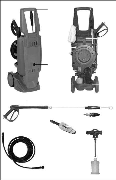
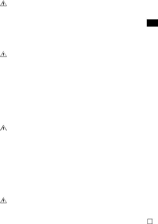
2.1 Identificazione dei Componenti
Si faccia anche riferimento alle figure 1 e 2, collocate all’inizio del manuale di uso e manutenzione
1 |
Cavo elettrico di alimentazione |
17 |
Spillo pulizia ugello |
2 |
Interruttore generale |
18 |
Testina ugello rotante (solo PW 136C - PW 145C - IP 1360S - |
3 |
Manubrio di movimentazione |
|
IP 1450S) |
4 |
Sede per idropistola/tubo lancia |
19 |
Lancia schiumogena |
5 |
Targhetta di avvertenza |
20 |
Dispositivo regolazione aspirazione detergente |
6 |
Avvolgitubo |
21 |
Boccetta detergente |
7 |
Targhetta di identificazione |
22 |
Idrospazzola (solo PW 136C - PW 145C - IP 1360S - IP 1450S) |
8 |
Raccordo uscita acqua |
23 |
Tubo alta pressione |
9 |
Sede per lancia schiumogena |
24 |
Attacco rapido tubo alta pressione |
10 |
Maniglia di sollevamento |
25 |
Fermo di sicurezza leva idropistola |
11 |
Ghiera di bloccaggio Securfix |
26 |
Leva idropistola |
12 |
Raccordo rapido ingresso acqua |
27 |
Testina portaugello |
13 |
Sede per cavo elettrico di alimentazione |
28 |
Tubo lancia |
14 |
Idropistola |
|
|
|
|
|
|
2.2 Dispositivi di Sicurezza
L’idropulitrice è corredata dei dispositivi di sicurezza illustrati di seguito.
a)Protettore termico
È un dispositivo che arresta il funzionamento dell’idropulitrice in caso di surriscaldamento del motore elettrico. In tal caso occorre procedere come segue :
•portare l’interruttore generale (2) in posizione “0” e staccare la spina dalla presa di corrente;
•premere la leva (26) dell’idropistola, in modo da scaricare la eventuale pressione residua;
•attendere 10÷15 minuti, in modo da far raffreddare l’idropulitrice;
•verificare che siano rispettate le prescrizioni contenute nel paragrafo “VERIFICHE EDALLACCIAMENTOALLA LINEA ELETTRICA”, con particolare riferimento alla verifica della prolunga eventualmente impiegata;
•ricollegare la spina elettrica alla presa e ripetere la procedura di avviamento descritta al paragrafo
“FUNZIONAMENTO”.

ATTENZIONE
•In caso di ripetuto intervento di tale dispositivo di sicurezza, non utilizzare assolutamente l’idropulitrice senza averla prima fatta verificare da un Tecnico Specializzato.
b)Valvola di limitazione/regolazione della pressione.
Èuna valvola, opportunamente regolata, che consente al fluido pompato di ritornare all’aspirazione della pompa, impedendo l’insorgere di pressioni pericolose, quando si chiude l’idropistola o si cerca di impostare valori di pressione al di sopra di quelli massimi consentiti.
c)Dispositivo di bloccaggio della leva dell’idropistola.
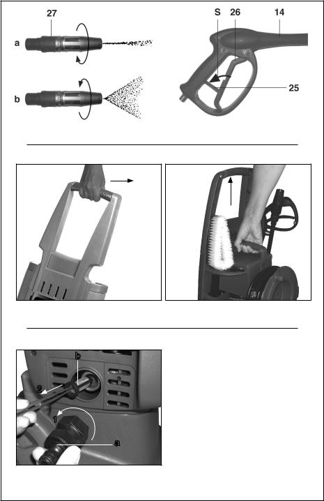
Èun fermo di sicurezza (25) che, premuto, consente di bloccare la leva (26) dell’idropistola (14) in posizione di chiusura, prevenendone funzionamenti accidentali (Fig. 4, posizione S).
2.3 Destinazione d’Uso
ATTENZIONE
•L’idropulitrice è esclusivamente destinata ai seguenti usi:
-lavaggio di veicoli, macchinari, edifici, utensili, ecc. con acqua fredda, eventualmente addizionata di detergenti previsti dal Costruttore;
-distribuzione di detergente previsti dal Costruttore;
-disincrostazione e disotturazione di tubazioni, tramite appositi accessori previsti dal Costruttore;
-idrosabbiatura di oggetti, tramite appositi accessori previsti dal Costruttore.
•L’idropulitrice non deve essere utilizzata per lavare persone, animali, apparecchiature elettriche sotto tensione, oggetti delicati o l’idropulitrice stessa.
•L’idropulitrice non è idonea ad essere utilizzata in ambienti che presentino condizioni particolari come, per esempio, atmosfere corrosive od esplosive.
• Per l’utilizzo a bordo di veicoli, navi od aerei, rivolgersi al servizio di assistenza tecnica del |
Costruttore, in |
quanto possono essere necessarie prescrizioni aggiuntive. |
|
Ogni altro uso è da ritenersi improprio. |
|
Il Costruttore non può essere considerato responsabile per eventuali danni derivanti da usi impropri od erronei.
3 Disimballaggio
ATTENZIONE
•Durante le operazioni di disimballaggio occorre indossare guanti ed occhiali di protezione, al fine di evitare danni alle mani ed agli occhi
•Gli elementi dell’imballo (sacchetti di plastica, graffette, ecc.) non debbono essere lasciati alla portata dei bambini, in quanto potenziali fonti di pericolo.
•Lo smaltimento dei componenti dell’imballaggio deve essere eseguito in conformità alle normative vigenti nel paese dove l’idropulitrice è stata installata.
In particolare, sacchetti ed imballaggi in materiale plastico non debbono essere abbandonati nell’ambiente, in quanto lo danneggiano.
•Dopo aver disimballato l’idropulitrice, occorre assicurarsi della sua integrità.
In caso di dubbio, non si deve assolutamente utilizzare l’idropulitrice, ma occorre rivolgersi ad un centro di assistenza autorizzato, che la farà verificare da un Tecnico Specializzato.
3.1 Targhetta di Identificazione e Targhette di Avvertenza
Si faccia riferimento alla Fig. 1, collocata all’inizio del manuale di uso e manutenzione.
La targhetta di identificazione (7) riporta il numero di serie e le principali caratteristiche tecniche dell’idropulitrice. Le targhette di avvertenza (5) informano sugli eventuali rischi residui quali: divieto di utilizzo dell’idropulitrice se prima non si è letto attentamente il manuale; divieto di utilizzo dell’idropulitrice per lavare persone, animali, apparecchiature elettriche e l’idropulitrice stessa.
ATTENZIONE
•Dopo aver disimballato l’idropulitrice, verificare che la targhetta di identificazione e le targhette di avvertenza siano presenti e leggibili. In caso contrario rivolgersi al rivenditore o ad un centro di assistenza autorizzato per il loro ripristino.
•Se durante l’uso la targhetta di identificazione o le targhette di avvertenza dovessero deteriorarsi, rivolgersi al
|
rivenditore o ad un centro di assistenza autorizzato per il loro ripristino. |
|
10 |
||
|
||
|
|
3.2 Dotazione Standard |
|
Accertarsi che nella confezione del prodotto che è stato acquistato siano contenuti i seguenti elementi: |
IT |
• idropulitrice ad alta pressione PW 121C - PW 136C - PW 145C - IP 1210S - IP 1360S - IP 1450S; |
|
• tubo di mandata ad alta pressione con attacco rapido; |
|
• idrospazzola (solo PW 136C - PW 145C - IP 1360S - IP 1450S); |
|
• tubo lancia |
|
• testina ugello rotante (solo PW 136C - PW 145C - IP 1360S - IP 1450S); |
|
• testina portaugello |
|
• lancia schiumogena; |
|
• manuale di uso e manutenzione; |
|
• spillo pulizia ugello; |
|
• manubrio; |
|
• 2 viti di fissaggio manubrio, |
|
Qualora dovessero esservi problemi, rivolgersi al rivenditore o ad un centro di assistenza autorizzato. |
|
3.3 Accessori Opzionali
È possibile integrare la dotazione standard dell’idropulitrice con la seguente ricca gamma di accessori:
•lancia sabbiante: ideata per levigare superfici, eliminando ruggine, vernice, incrostazioni, ecc.;
•sonda spurgatubi: ideata per disotturare tubazioni e condutture;
•idrospazzola rotante: ideata per la pulizia di superfici delicate;
•lancia lavapavimenti.
ATTENZIONE
•Accessori opzionali non adeguati pregiudicano il funzionamento dell’idropulitrice e la possono rendere pericolosa. Utilizzare esclusivamente accessori opzionali originali raccomandati dal Costruttore.
Per quanto riguarda le prescrizioni generali, le avvertenze di sicurezza, l’installazione e la manutenzione degli accessori opzionali, occorre fare riferimento alla documentazione che li accompagna.
4 Installazione
4.1 Montaggio degli Accessori
a)Inserire il manubrio di movimentazione (3) sul corpo dell'idropulitrice. Accertarsi che il manubrio sia inserito a fondo sul corpo dell'idropulitrice (le superfici frontali devono risultare allineate). Fissare il manubrio con le 2 viti
in dotazione (cacciavite a croce non fornito). Operazione A di Fig. 2.
b)La versione è fornita di un tubo lancia (28) sul quale può essere inserita, tramite un innesto a baionetta, una testina portaugello standard (27), oppure una testina con ugello rotante (18). In funzione del lavoro che si intende svolgere, procedere al montaggio di una delle due testine, inserendola nel tubo lancia e ruotandola in senso orario fino al completo bloccaggio dell’innesto, ed infine bloccandola ruotando in senso orario la ghiera Securfix (11). Operazione I di Fig. 2. Per lo smontaggio, sbloccare la ghiera Securfix (11) ruotandola in senso anti-orario, mantenere la testina premuta nella sede del tubo lancia e ruotarla in senso antiorario fino al suo sblocco, quindi sfilarla completamente.
Operazione H di Fig. 2.
c)Srotolare il tubo alta pressione (23), collegare il raccordo ad attacco rapido (24) con il raccordo di uscita acqua (8), avvitare e serrare. Operazione C di Fig. 3.
d)Avvitare l’estremità del tubo alta pressione (23) (lato senza attacco rapido) al filetto dell’idropistola (14) e serrare a fondo con due chiavi fisse da 17 mm (non in dotazione). Operazione D di Fig. 3.
4.2 Verifiche ed Allacciamento alla Rete Idrica
AVVERTENZA
•L’alimentazione idrica deve essere tale da poter garantire una adeguata erogazione di portata d’acqua per l’idropulitrice, a questo scopo fare riferimento ai valori riportati nella tabella dati tecnici. In caso di dubbi rivolgersi ad un Tecnico Specializzato.
•Non alimentare l’idropulitrice con acqua a temperatura superiore a 40 ºC/98 ºF od inferiore a 5ºC/41ºF.
•La pressione dell’acqua di alimentazione non deve essere superiore a 8 bar/116 psi.
•Non far funzionare l’idropulitrice con profondità di adescamento superiori a 0 m/0 ft.
•Non far funzionare l’idropulitrice senza alimentazione idrica.
•Non alimentare l’idropulitrice con acqua salmastra o contenente impurità. Qualora ciò dovesse accadere, far funzionare l’idropulitrice per alcuni minuti con acqua pulita.
11

ATTENZIONE
• Attenersi alle prescrizioni di collegamento alla rete idrica vigenti nel paese in cui viene installata l’idropulitrice.
4.3 Verifiche ed Allacciamento alla Linea Elettrica
ATTENZIONE
•Fare verificare da un Tecnico Specializzato che l’alimentazione dell’impianto elettrico sia conforme ai dati riportati sulla targhetta di identificazione (7) apposta sull’idropulitrice. In particolar modo la tensione di alimentazione non deve differire da quella riportata nella targhetta di ± 5%.
•Il collegamento alla rete elettrica deve essere predisposto da un Elettricista Qualificato, in ottemperanza alla norma IEC 364 od a norme equivalenti in vigore nel paese dove viene utilizzata l’idropulitrice. In particolare la presa di corrente alla quale si collega l’idropulitrice deve essere munita di conduttore di terra, di adeguato fusibile (il valore è riportato sulla targhetta di identificazione ed in tabella dati tecnici) e deve essere protetta da un interruttore magnetotermico differenziale di sensibilità non superiore a 30 mA.
•Qualora il cavo di alimentazione fosse troppo corto, è possibile utilizzare una prolunga, assicurandosi che non superi i 10 m/32,8 ft, che la sezione dei conduttori sia di almeno 1,5 mm² e che la spina e la presa siano del tipo a tenuta stagna. Per rispettare tutte queste prescrizioni occorrerà rivolgersi ad un Elettricista Qualificato.
Le prolunghe non adeguate possono essere pericolose.
5 Funzionamento
ATTENZIONE
•L’utilizzo dell’idropulitrice richiede attenzione e prudenza. Non affidare ad altri l’idropulitrice senza esserci accertati, sotto la propria diretta responsabilità, che l’utente occasionale abbia letto attentamente questo manuale e conosca l’uso dell’idropulitrice. Le idropulitrici non devono essere usate da bambini o da personale non addestrato.
•Rispettare le avvertenze di sicurezza contenute nel manuale di uso e manutenzione degli eventuali accessori opzionali che vengono utilizzati.
•Non utilizzare l’idropulitrice nel caso in cui:
-il cavo di alimentazione od altre parti importanti come il tubo alta pressione, i dispositivi di sicurezza, l’idropistola e la lancia siano danneggiati;
-l’idropulitrice si sia rovesciata od abbia subito forti urti;
-vi siano evidenti perdite di acqua.
In tali casi fate controllare l’idropulitrice da un Tecnico Specializzato.
•Particolare attenzione deve essere riservata all’uso dell’idropulitrice in ambienti in cui vi siano veicoli in movimento, che possono schiacciare o lesionare il cavo di alimentazione, il tubo alta pressione, l’idropistola, ecc...
•Durante il funzionamento tenere sempre sotto sorveglianza l’idropulitrice e fuori dalla portata dei bambini. In particolare prestare grande attenzione nell’uso presso asili nido, case di cura e case di riposo, in quanto in tali luoghi possono esservi bambini, persone anziane o disabili senza sorveglianze
•Prima di far funzionare l’idropulitrice, curare di disporla in un luogo asciutto, in piano ed in posizione stabile, onde evitare cadute o ribaltamenti.
•Eseguire le operazioni descritte nel paragrafo “Arresto” prima di spostare l’idropulitrice.
•Prima dell’avviamento dell’idropulitrice, indossare indumenti che garantiscano una adeguata protezione da errate manovre con il getto d’acqua in pressione. Non usare l’idropulitrice in prossimità di persone, se queste non indossano indumenti protettivi.
•I getti ad alta pressione possono essere pericolose se usati impropriamente. Non dirigere il getto verso persone, animale, apparecchiature elettriche sotto tensione o verso l’idropulitrice stessa.
•Durante l’uso impugnare saldamente l’idropistola, perché quando si agisce sulla leva (26), si è sottoposti alla forza di reazione del getto ad alta pressione. L’entità di tale forza di rinculo è riportata in tabella dati tecnici (la forza di rinculo è espressa in N, ove 1 N = 0,1 kg)
•Non dirigere il getto contro se stessi od altre persone per pulire indumenti o calzature.
•A salvaguardia dell’ambiente, il lavaggio di motori di veicoli o di macchinari contenenti circuiti idraulici deve essere effettuato solamente in ambienti dotati di adeguato separatore d’olio.
•I pneumatici dei veicoli debbono essere lavati da una distanza non inferiore a 50 cm/19 in, per evitare che il getto ad alta pressione li danneggi. Prima manifestazione del danno apportato ad uno pneumatico è la sua alterazione di colore.
•Non dirigere il getto ad alta pressione verso materiali contenenti amianto od altre sostanza dannose per la 12 salute.

• Non usare l’idropulitrice sotto la pioggia. |
|
• Prestare particolare attenzione a quanto esposto nel paragrafo “Verifiche ed allacciamento alla linea |
IT |
elettrica”. |
•Prestare particolare attenzione a quanto esposto nel paragrafo “Funzionamento con detergente”.
•Quando non in funzione, non lasciare l’idropulitrice con la spina inserita nella presa di corrente e comunque disinserirla prima di qualsiasi intervento. Più specificamente portare sempre l’interruttore generale (2) in posizione “0”, togliere la spina dalla presa di corrente, premere la leva (26) dell’idropistola per scaricare la eventuale pressione residua e portare in posizione di blocco il fermo di sicurezza (25) (Fig. 4 - Posizione S):
-prima di lasciare senza sorveglianza, anche se per breve tempo, l’idropulitrice;
-dopo l’uso, aspettare, inoltre, che idropulitrice si sia anche completamente raffreddata prima di ogni pulizia o manutenzione.
•Durante l’uso, non bloccare la leva (26) dell’idropistola in posizione di sempre aperto.
•Non estrarre la spina dalla presa di corrente tirando il cavo di alimentazione.
•Non interporre riduzioni od adattatori fra spina elettrica e presa di corrente.
•Mantenere il cavo di alimentazione, le eventuali prolunghe, le spine e le prese asciutti. Non toccarli con le mani bagnate.
•Qualora il cavo di alimentazione fosse danneggiato, per la sua sostituzione, onde evitare un pericolo, rivolgersi al Costruttore o ad un Tecnico Specializzato.
•Durante il funzionamento non coprire l’idropulitrice e non collocarla dove ne sia pregiudicata la ventilazione.
•Quando si utilizza l’idropulitrice in ambienti chiusi, assicurarsi che sia garantita una corretta ventilazione.
5.1 Movimentazione
•Per la movimentazione dell'idropulitrice utilizzare il manubrio (3) come indicato in Fig. 5 operazione M.
•Per il sollevamento utilizzare la maniglia (10) Fig. 5 operazione N.
ATTENZIONE
Non utilizzare il manubrio di movimentazione (3) per il sollevamento dell'idropulitrice.
5.2 Attività Preliminari
•Srotolare completamente il tubo alta pressione (23).
•Fissare al raccordo rapido d’ingresso acqua (12) un tubo di alimentazione, utilizzando un comune raccordo rapido da giardinaggio. Operazione E di Fig. 3.
•Aprire il rubinetto di alimentazione acqua, facendo attenzione a che non vi siano gocciolamenti. Operazione F di Fig. 3.
•Accertarsi che l’interruttore generale (2) sia in posizione di spento (posizione “0”) ed innestare la spina nella presa di corrente elettrica. Operazione G di Fig. 3.
•Premere l’interruttore generale (2), in posizione “1”.
•Premere la leva (26) dell’idropistola ed attendere che fuoriesca un getto d’acqua continuo.
•Portare l’interruttore generale (2) in posizione “0” e collegare all’idropistola (14) il tubo lancia (28), serrando a fondo.
Operazione B di Fig. 3.
5.3 Funzionamento Standard (ad Alta Pressione)
•Riavviare l’idropulitrice portando in posizione “1” l’interruttore generale (2).
Nota: durante tale avvio l’idropulitrice si arresterà immediatamente dopo lo spunto di partenza in quanto viene attivato il dispositivo Total Stop.
•Per far entrare in funzione l’idropulitrice, iniziando così le operazioni di lavaggio, sarà sufficiente azionare la leva (26) dell’idropistola.
•La regolazione angolare del getto è possibile agendo sulla testina (27) (Fig. 4 - Posizioni a e b).
5.4 Funzionamento con Detergente
ATTENZIONE |
|
• L’idropulitrice è stata progettata per essere usata con i detergenti raccomandati dal Costruttore. L’uso di altri |
|
detergenti o prodotti chimici può influenzare negativamente la sicurezza dell’idropulitrice. |
|
In particolare non aspirare mai liquidi contenenti solventi, benzina, diluenti, acetone ed olio combustibile, in quanto |
|
il prodotto nebulizzato è altamente infiammabile, esplosivo e tossico. |
|
• Leggere attentamente le prescrizioni ed avvertenze riportate sull’etichetta del detergente utilizzato. |
|
• Conservare i detergenti in un luogo sicuro ed inaccessibili ai bambini. |
|
• In caso di contatto con gli occhi lavare immediatamente con acqua e rivolgersi subito ad un medico portando |
13 |
con sé la confezione di detergente. |
|

•In caso di ingestione, non indurre il vomito e rivolgersi subito ad un medico portando con sé la confezione di detergente.
I detergenti raccomandati, sono biodegradabili oltre il 90 %.
Per le modalità di impiego del detergente, fare riferimento a quanto riportato in tabella e sull’etichetta della confezione di detergente.
•Riempire la boccetta (21) col detergente desiderato.
•Regolare la capacità di aspirazione del detergente nel seguente modo:
-disinserire l’asta (20) dalla lancia (19);
-far collimare il dentello L dell’asta (20) con uno dei numeri riportati all’interno della lancia (19) (1: aspirazione minima, 6: aspirazione massima);
-reinserire l’asta (20) nella lancia (19).
•Innestare la boccetta (21) nella lancia schiumogena (19).
•Portare l’interruttore generale (2) in posizione “0” e collegare la lancia (19) all’idropistola (14).
•Riavviare l’idropulitrice, portando l’interruttore generale (2) in posizione “1” ed azionare la leva (26) (l’aspirazione e la miscelazione avvengono automaticamente al passaggio dell’acqua).
5.5 Interruzione del Funzionamento (total stop)
Rilasciando la leva (26) dell’idropistola, l’idropulitrice si arresta automaticamente.
L’idropulitrice riprende a funzionare regolarmente alla successiva pressione della leva dell’idropistola.
ATTENZIONE
•Si ricordi che quando l’idropulitrice è in Total Stop è a tutti gli effetti in funzione, quindi prima di lasciarla senza sorveglianza, anche se per breve tempo, portare sempre l’interruttore generale (2) in posizione “0”, togliere la spina dalla presa di corrente, premere la leva (26) dell’idropistola per scaricare la eventuale pressione residua e portare in posizione di blocco il fermo di sicurezza (25) (Fig. 4 - Posizione S).
6 Arresto e Messa a Riposo
Ultimate le operazioni di lavaggio, procedere all’arresto ed alla messa a riposo dell’idropulitrice.
6.1 Arresto
•Chiudere completamente il rubinetto di alimentazione dell’acqua.
•Svuotare dall’acqua l’idropulitrice facendola funzionare per alcuni secondi con la leva (26) dell’idropistola premuta.
•Portare l’interruttore generale (2) in posizione “0”.
•Togliere la spina di alimentazione dalla presa di corrente.
•Eliminare l’eventuale pressione residua rimasta nel tubo alta pressione (23), tenendo premuta per alcuni secondi la leva (26) dell’idropistola.
•Riavvolgere con cura il cavo di alimentazione (1) ed inserirlo nella apposita sede (13).
•Attendere che l’idropulitrice si sia raffreddata.
ATTENZIONE
•Quando viene fatta raffreddare l’idropulitrice, prestare attenzione:
-a non lasciare incustodita l’idropulitrice se vi sono bambini, anziani o disabili non sorvegliati;
-a disporre l’idropulitrice in una posizione stabile senza pericolo di cadute;
-a non mettere l’idropulitrice a contatto o nelle immediate vicinanze di materiali infiammabili.
6.2 Messa a Riposo
•Riavvolgere il tubo alta pressione (23) con cura, nell'avvolgitubo (6) evitando piegature.
•Riavvolgere con cura il cavo di alimentazione (1) ed inserirlo nella apposita sede (13).
•Riporre con cura l’idropulitrice in un luogo asciutto e pulito, facendo attenzione a non danneggiare il cavo di alimentazione ed il tubo alta pressione.
AVVERTENZA
•L’idropulitrice teme il gelo.
In ambienti rigidi, al fine di evitare formazioni di ghiaccio all’interno dell’idropulitrice, è possibile, prima di procedere alla procedura di “Arresto”, fare aspirare all’idropulitrice un prodotto antigelo automobilistico, dopo aver consultato un Tecnico Specializzato, in quanto il liquido pompato potrebbe danneggiare le guarnizioni della
pompa ad alta pressione.
14 In ambienti rigidi, se non è stato possibile proteggere l’idropulitrice come illustrato in precedenza, prima di

avviarla portarla in un ambiente caldo per un tempo sufficiente a far sciogliere l’eventuale ghiaccio formatosi al |
|
suo interno. |
IT |
Il mancato rispetto di queste semplici prescrizioni può comportare seri danni all’idropulitrice. |
7 Pulizia e Manutenzione
ATTENZIONE
•Ogni intervento di pulizia e manutenzione deve essere effettuato solo dopo aver eseguito le operazioni descritte nel paragrafo “Arresto”.
In particolar modo occorre ricordare di scollegare sempre l’alimentazione elettrica.
•Per garantire la sicurezza dell’idropulitrice utilizzare solo ricambi originali forniti dal Costruttore o da lui approvati.
•I tubi di gomma, i raccordi e le lance ad alta pressione sono importanti per la sicurezza: utilizzare esclusivamente quelli raccomandati dal Costruttore.
7.1 Manutenzione Ordinaria
Eseguire le operazioni descritte nel paragrafo “Arresto” ed attenersi a quanto riportato nella tabella seguente.
INTERVALLO DI MANUTENZIONE |
INTERVENTO |
|
|
Ad ogni uso |
• Controllo cavo di alimentazione, tubo alta pressione, raccordi, idropistola, |
|
tubo lancia |
|
Qualora uno o più particolari risultassero danneggiati, non utilizzare |
|
assolutamente l’idropulitrice e rivolgersi ad un Tecnico Specializzato. |
|
|
Settimanalmente |
• Pulizia filtro ingresso acqua |
|
Smontare il raccordo di entrata acqua (a) e con una pinza estrarre il filtro (b) |
|
(si veda la Fig. 5). Per la pulizia, in genere è sufficiente passare il filtro sotto |
|
un getto d’acqua corrente, o soffiarlo con aria compressa. Nei casi più difficili, |
|
usare un prodotto anticalcare o sostituirlo, rivolgendosi per l’acquisto del |
|
ricambio ad un centro assistenza autorizzato. |
|
Rimontare il filtro e serrare a fondo il raccordo. |
|
|
Mensilmente |
• Pulizia ugello. |
|
Per la pulizia, in genere è sufficiente passare entro il foro dell’ugello lo spillo |
|
(17) in dotazione. Qualora non si ottengano risultati apprezzabili rivolgersi ad |
|
un centro di assistenza autorizzato. |
|
|
AVVERTENZA
•Durante il funzionamento, l’idropulitrice non deve essere troppo rumorosa e sotto di essa non vi devono essere evidenti gocciolamenti di acqua o di olio.
Qualora ciò dovesse accadere, fare controllare la macchina da un Tecnico Specializzato.
7.2 Manutenzione Straordinaria
ATTENZIONE
• Gli interventi di manutenzione straordinaria debbono essere eseguiti solamente da un Tecnico Specializzato.
Per la manutenzione straordinaria attenersi a quanto riportato nella tabella seguente.
INTERVALLO DI MANUTENZIONE |
INTERVENTO |
|
|
Ogni 50 ore |
Controllo circuito idraulico pompa. |
|
Controllo fissaggio pompa. |
|
|
Ogni 100 ore |
Sostituzione olio pompa. |
|
Controllo valvole aspirazione/mandata pompa. |
|
Controllo serraggio viti pompa. |
|
Controllo valvola di regolazione pompa. |
|
Verifica dei dispositivi di sicurezza. |
|
|
AVVERTENZA
• I dati riportati in tabella sono indicativi.
15

8 Demolizione e Smaltimento
La demolizione dell’idropulitrice va eseguita solamente da personale qualificato ed in conformità alla legislazione vigente nel paese in cui è stata installata.
In particolare, il simbolo  presente sulla targhetta di identificazione (7), indica che il prodotto non deve essere smaltito assieme ai rifiuti domestici.
Per ulteriori indicazioni rivolgetevi al locale servizio di smaltimento rifiuti od al vostro rivenditore.
ATTENZIONE
•Prima di rottamare l’idropulitrice, renderla inservibile, ad esempio tagliandone il cavo di alimentazione e rendere innocue quelle parti che potrebbero costituire un pericolo per dei bambini che si servissero dell’idropulitrice per i loro giochi.
9 Inconvenienti, Cause e Rimedi
ATTENZIONE
•Prima di effettuare ogni intervento eseguire le operazioni descritte nel paragrafo “Arresto”. Qualora non si riesca a ripristinare il corretto funzionamento dell’idropulitrice con l’ausilio delle informazioni contenute nella tabella seguente, rivolgersi ad un Tecnico Specializzato.
|
|
INCONVENIENTI |
CAUSE |
RIMEDI |
|
|
|
|
|
|
|
Portando l’interruttore (2) in |
È intervenuto un dispositivo di |
Ripristinare il dispositivo di protezione. |
|
|
posizione “1”, l’idropulitrice |
sicurezza dell’impianto a cui è |
In caso di nuovo intervento non utilizzare |
|
|
non si avvia. |
collegata l’idropulitrice (fusibile, |
l’idropulitrice e rivolgersi ad un Tecnico |
|
|
Si ricordi anche quanto |
interruttore differenziale ecc.). |
Specializzato. |
|
|
riportato nella Nota del |
|
|
|
|
paragrafo “Interruzione del |
La spina del cavo di alimentazione |
Scollegare la spina dalla presa e ricollegarla |
|
|
funzionamento (Total Stop)”. |
non è inserita correttamente. |
correttamente. |
|
|
|
|
|
|
|
L’idropulitrice vibra molto |
Il filtro ingresso acqua (Fig. 6) è |
Attenersi a quanto riportato nel paragrafo |
|
|
ed è rumorosa. |
sporco. |
“Manutenzione ordinaria”. |
|
|
|
L’alimentazione idrica è insufficiente. |
Verificare che il rubinetto sia completamente |
|
|
|
|
aperto e che la portata della rete idrica.sia |
|
|
|
|
conforme a quanto riportato nel paragrafo |
|
|
|
|
“Caratteristiche e dati tecnici”. |
|
|
|
|
|
|
|
Scarsa aspirazione |
Il dispositivo di regolazione |
Operare secondo quanto riportato nel |
|
|
detergente. |
dell’aspirazione detergente (20) non è |
paragrafo “Funzionamento con detergente” |
|
|
|
correttamente impostato. |
|
|
|
|
Mancanza di prodotto nella boccetta. |
Aggiungere prodotto. |
|
|
|
Il detergente utilizzato è troppo |
Utilizzare un detergente raccomandato dal |
|
|
|
viscoso |
costruttore (si veda la tabella detergenti), |
|
|
|
|
attenendosi alle diluizioni riportate sulla |
|
|
|
|
targhetta. |
|
|
|
|
|
|
|
Dall’ugello non esce acqua. |
Manca l’acqua. |
Verificare che il rubinetto della rete idrica sia |
|
|
|
|
completamente aperto. |
|
|
|
Ugello acqua otturato. |
Pulire e/o sostituire l’ugello secondo quanto |
|
|
|
|
riportato nel paragrafo “Manutenzione |
|
|
|
|
ordinaria”. |
|
|
|
|
|
|
|
L’idropulitrice si arresta |
È intervenuto un dispositivo di |
Ripristinare il dispositivo di protezione. |
|
|
durante il funzionamento. |
sicurezza dell’impianto a cui è |
In caso di nuovo intervento non utilizzare |
|
|
|
collegata l’idropulitrice (fusibile, |
l’idropulitrice e rivolgersi ad un Tecnico |
|
|
|
interruttore differenziale, ecc). |
Specializzato. |
|
|
|
È intervenuto il dispositivo di |
Attenersi a quanto riportato nel paragrafo |
|
|
|
protezione termica. |
“Dispositivi di sicurezza”. |
|
|
|
|
|
|
|
Ruotando l’interruttore |
L’impianto elettrico e/o la prolunga |
Attenersi a quanto riportato nel paragrafo |
|
|
generale (2) il motore ronza, |
non sono adeguati. |
“Verifiche ed allacciamento alla linea |
16 |
|
ma non parte |
|
elettrica”. |
|
|
|
|
|
1 General Information
Congratulations for choosing one of our products. We would like to remind you that we took the safety of the operator, the efficiency of its use and the protection of the environment into great consideration when designing and manufacturing this product.
In order to preserve its features over time, please read and follow these instructions carefully.
Particular attention must be awarded to the parts with the following symbol: GB
WARNING
as they contain important instructions regarding safety when using the water cleaner.
The Manufacturer is not liable for damage caused by:
•failure to comply with these instructions;
•use of the water cleaner not included in the “INTENDED USE” section;
•failure to comply with current safety regulations and regulations for the prevention of accidents in the workplace;
•incorrect installation;
•failure to carry out the prescribed maintenance;
•modifications or actions without the authorisation by the Manufacturer;
•use of non-original or unsuitable spare parts for this model of water cleaner;
•repairs which were not carried out by a Skilled Technician.
1.1 Address of the Manufacturer
The address of the manufacturer is given in the declaration of conformity at the end of this part of the instruction manual.
1.2 Use And Conservation of these Operating and Maintenance Manual
The operating and maintenance instructions are an integral part of the water cleaner and they must be kept in a safe place for future reference so that they may be readily consulted in case of need.
The operating and maintenance instructions contain important information for the safety of the operator and of any people near him and for the protection of the environment.
In case of deterioration or loss, a new copy should be requested from the dealer or from an authorised service centre.
If the water cleaner is passed on to a third party, please make sure these operating and maintenance instructions are also given to the new owner.
We take great care when drawing up our instructions. If you note any mistakes, please do inform the Manufacturer or an authorised service centre.
The Manufacturer reserves the right to modify, update and correct these instructions without notice. It is illegal to copy these instructions, even partially, without prior authorisation by the Manufacturer.
1.3 Symbols and Terms
1.3.1 Symbols
The symbol:
WARNING
next to certain parts of the text, is to indicate that there is the firm possibility of injury to persons if the relative instructions and indications are not followed.
The symbol:
CAUTION
next to certain parts of the text is to indicate that there is the possibility of damaging the water cleaner if the relative instructions are not followed.
1.3.2 Terms
•Skilled Technician: a person, generally from the service centre, who has received appropriate training and is authorised to carry out special maintenance and repairs on the water cleaner. Any work on is electrical parts must be carried out by a Skilled Technician who is also a Qualified Eletrician, i.e. a person with professional training who is authorised to check, install and repair electrical equipment correctly and according to current regulations in the country where the water cleaner is installed.
•Total Stop: this stops operation of the water cleaner every time the control lever on the cleaner gun is released.
•Easy Start: this aids starting up the water cleaner by lowering the pressure for the first moments of its operation. 17

2 Features and Technical Specifications
|
PW 121C - IP 1210S |
PW 136C - IP 1360S |
PW 145C - IP 1450S |
||
|
|
|
|
|
|
ELECTRICAL CONNECTION |
|
|
|
|
|
Mains power supply |
230 V / 1~50 Hz |
230 V / 1~50 Hz |
230 V / 1~50 Hz |
||
Absorbed power |
1,7 kW |
2,0 kW |
2,3 kW |
||
Fuse |
16 A |
16 A |
|
16 A |
|
HYDRAULIC CONNECTION |
|
|
|
|
|
Maximum inlet water temperature |
40 °C / 98 °F |
40 °C / 98 °F |
40 °C / 98 °F |
||
Minimum inlet water temperature |
5 °C / 41 °F |
5 °C / 41 °F |
5 °C / 41 °F |
||
Minimum inlet water flow |
450 l/h / 120 US gph |
500 l/h / 132 US gph |
600 l/h / 159 US gph |
||
Maximum inlet water pressure |
0,8 MPa / 8 bar / 116 psi |
0,8 MPa / 8 bar / 116 psi |
0,8 MPa / 8 bar / 116 psi |
||
Maximum priming depth |
0 m / 0 ft |
0 m / 0 ft |
0 m / 0 ft |
||
|
|
|
|
|
|
PERFORMANCE |
|
|
|
|
|
Water flow |
360 l/h / 95 US gph |
410 l/h / 108 US gph |
480 l/h / 127 US gph |
||
Maximum pressure |
13 MPa / 130 bars / 1885 psi |
14 MPa / 140 bars / 2031 psi |
15 MPa / 150 bars / 2175 psi |
||
Recoil of cleaner gun |
11 N |
14 N |
|
15 N |
|
Sound level |
76,2 dB (A) |
77,3 dB (A) |
77,3 dB (A) |
||
Operator arm vibrations |
0,73 m/s2 |
1,31 m/s2 |
1,31 m/s2 |
||
WEIGHT AND DIMENSION |
|
|
|
|
|
Lenght x width x height |
310 x 308 x 820 mm |
/ 12 x 12 x 32 in |
|||
|
|
|
|
|
|
Weight |
12 kg / 26 lb |
13 kg |
/ |
29 lb |
13 kg / 29 lb |
|
|
|
|
|
|
Detergent bottle capacity |
|
0,35 l / |
0,09 US gal |
|
|
|
|
|
|
|
|
Allfeaturesandtechnicalspecificationsareonlyindications.TheManufacturerreservestherighttomodifytheapplianceasitdeemsnecessary.
2.1 Identification of Components
Please also refer to figures 1 to 2, which are located at the start of these operating and maintenance instructions.
1 |
Electric power cord |
17 |
Nozzle cleaning pin |
2 |
Main switch |
18 |
Rotojet rotating nozzle head (PW 136C - PW 145C IP 1360S - |
3 |
Handling bar |
|
IP 1450S only) |
4 |
Housing for water gun / lance hose |
19 |
Foaming lance |
5 |
Warning notice |
20 |
Detergent intake adjuster |
6 |
Hose reel |
21 |
Opening for detergent |
7 |
Identification plate |
22 |
Water brush (PW 136C - PW 145C IP 1360S - IP 1450S only) |
8 |
Water outlet connector |
23 |
High pressure hose |
9 |
Housing for foaming lance |
24 |
Quick fit connector for high-pressure hose |
10 |
Lifting handle |
25 |
Safety catch on water gun lever |
11 |
Securfix ring nut |
26 |
Water gun lever |
12 |
Water inlet quick-fit connector |
27 |
Nozzle support head |
13 |
Housing for electric power cord |
28 |
Lance hose |
14 |
Water gun |
|
|
|
|
|
|
2.2 Safety Devices
This water cleaner is provided with the following safety devices: a) Thermal protector
It’s a device that stops the water cleaner operation in case of motor overheating. In this case, proceed as follows:
•switch the main switch (2) to position “0” and remove the plug from the power outlet;
•press the lever (26) on the cleaner gun to eliminate any remaining pressure;
•wait 10 to 15 minutes until the water cleaner cools down;
•check that the instructions in the “CHECKS AND CONNECTION TO THE MAINS ELECTRICITY SUPPLY” section have been followed, particularly regarding any extension cord used;
•replace the electric plug in the power outlet and repeat the start-up procedure described in the “OPERATION” section.
18
WARNING |
|
• If this safety device cuts in repeatedly, do not use the water cleaner until it has been checked by a Skilled |
|
Technician. |
|
b)Pressure limit/adjustment valve |
|
When this valve has been correctly set, the pumped fluid is able to return to the pump’s suction unit, thus preventing |
GB |
the creation of dangerous levels of pressure when the cleaner gun is stopped or should pressure be set that is above |
|
allowed levels. |
|
c)Safety stop on cleaner gun lever
This is a safety catch (25) which, when pressed, lets you block the lever (26) on the cleaner gun (14) to prevent the possibility of it being started by accident (see also Fig. 4, pos. S)
2.3 Intended Use
WARNING
•This water cleaner is to be used exclusively for:
-cleaning vehicles, machinery, buildings, tools etc with cold water, possibly with the addition of detergents as per the Manufacturer’s instructions;
-distributing detergents as per the Manufacturer’s instructions;
-removing lime scale and unblocking pipe work using the appropriate tools as per the Manufacturer’s instructions;
-water sanding objects using the appropriate tools as per the Manufacturer’s instructions;
•The water cleaner must not be used to wash people, animals, energized electrical appliances, delicate objects or the high pressure cleaner itself.
•The high pressure cleaner is not suitable for use in certain situations such as in corrosive or explosive atmospheres.
•Contact the Manufacturer’s service centre before use on board vehicles, ships or airplanes, as there may be additional instructions for use.
Any other use is considered improper.
The Manufacturer is not liable for any damage caused by improper or incorrect use.
3 Removing The Appliance From Its Packing Materials
WARNING
•Protective gloves and glasses must be worn when removing the appliance from the packing materials to prevent injury to the hands and eyes.
•The packing materials (plastic bags, staples etc.) must not be left in reach of children, as they are potentially dangerous.
•The packing materials must be disposed of according to current regulations in the country where the water cleaner is installed.
In particular, plastic bags and packaging must never be abandoned, as they are harmful to the environment.
•After removing the appliance from the packing materials, check that no parts are missing.
In case of doubt, do not use the water cleaner but contact an authorised service centre so that a Skilled Technician can check the appliance.
3.1 Identification Label and Warning Labels
See Fig. 1 at the front of these operating and maintenance instructions.
The identification label (7) contains the serial number and the main technical specifications of the water cleaner. The warning labels (5) inform you of any other risks, such as: do not use the high pressure cleaner unless you have read the instructions manual; do not use the high pressure cleaner for washing people, animals, electrical equipment or the high-pressure cleaner itself.
WARNING
•After removing the appliance from the packing materials, check that the identification label and the warning labels are present and are legible. If this is not the case, contact your dealer or an authorised service centre so they can be replaced.
•If the identification label and the warning labels deteriorate during use, contact your dealer or an authorised
service centre so they can be replaced. |
19 |
|

3.2 Standard Accessories
Make sure that in the product package that was bought there are the following elements:
•high-pressure water cleaner (PW 121C - PW 136C - PW 145C - IP 1210S - IP 1360S - IP 1450S);
•high-pressure delivery pipe with fast coupling;
•water brush (PW 136C - PW 145C - IP 1360S - IP 1450S only);
•lance hose;
•rotating nozzle head (PW 136C - PW 145C - IP 1360S - IP 1450S only);
•nozzle support head
•foaming lance;
•use and maintenance manual;
•nozzle cleaning pin;
•handlebar;
•2 screws to secure handle,
In case of problems, apply to the dealer or to an authorised service centre.
3.3 Optional Accessories
The standard accessories for the high pressure cleaner can be integrated with the following vast range of accessories:
•Sandblasting lance: designed for smoothing down surfaces, eliminating rust, paint, deposits etc.
•Pipe-draining probe: designed for unblocking pipes and ducts.
•Rotating water jet brush: designed for cleaning delicate surfaces.
•floor cleaning lance.
WARNING
•The operation of the water cleaner may be impaired if unsuitable accessories are used and they may even make it dangerous. Only use original accessories endorsed by the Manufacturer.
Refer to the documents provided with the optional accessories for information regarding their general use, safety warnings, installation and maintenance.
4 Installation
4.1 Assembling the Accessories
a)Insert the handling bar (3) onto the body of the high pressure cleaner. Make sure you fully insert the bar into the high-pressure cleaner’s body (the front surfaces must be aligned with one another). Secure the bar with the 2 screws supplied (cross head screwdriver not supplied). Step A in Fig. 2
b)The version are supplied with a lance hose (28) which can be fitted with a standard nozzle support head (27), or a head with a rotating nozzle (18), using a bayonet mount.
Depending on the job to be done, fit one of the two heads by inserting it into the lance hose and turning it clockwise until it clicks securely onto the coupling. Now block it in place with the Securfix ring nut (11), by turning it clockwise. Step I in Fig. 2.
To remove the head, turn the Securfix ring nut (11) anti-clockwise and remove it. Keep the head pressed down into the lance hose housing and turn it anticlockwise until it is released, then remove it completely. Step H in Fig. 2.
c)Unroll the high-pressure hose (23), connect the quick-fit connector (24) to the water outlet connector (8), screw down and secure. Step C in Fig. 3.
d)Screw the end of the high pressure hose (23) (the end without the quick fit connector) onto the thread of the spray gun (14) and secure it tightly using two 17 mm socket keys (not supplied). Step D in Fig. 3.
|
4.2 Checks and Connection to the Mains Water Supply |
|
|
CAUTION |
|
|
• The water supply must be able to guarantee the adequate delivery of water flow to the high pressure cleaner; refer |
|
|
to the table of technical specifications. |
|
|
In case of doubt, contact a Skilled Technician. |
|
|
• Do not supply the water cleaner with water at a temperature in excess of 40°C/98°F or below 5°C/41°F. |
|
|
• The pressure of the water supply must not be in excess of 8 bar/116 psi. |
|
|
• Do not operate the high pressure cleaner with a priming depth in excess of 0 m/0 ft. |
|
|
• Do not operate the high pressure cleaner if it is not connected to a water supply. |
|
20 |
||
• Do not supply the high pressure cleaner with salt water or water containing impurities. In this event, run the high |
||
|
pressure cleaner for a few minutes with clean water.
WARNING
•Follow current regulations for connection to the mains water supply in the country where the water cleaner is installed.
GB
4.3 Checks and Connection to the Mains Electricity Supply
WARNING
•A Skilled Technician must check that the electrical supply complies with the data indicated on the identification label (7) on the high pressure cleaner. It is especially important that the supply voltage does not differ more than ±5% from that indicated on the label.
•All connections to mains electricity must be carried out by a Qualified Eletrician according to IEC 364 regulations or the equivalent standard in the country where the high pressure cleaner is to be used. It is especially important that the current outlet where the high pressure cleaner is connected is provided with an earth conductor and a suitable fuse (according to the size indicated on the identification label and in the table of technical specifications), and must be protected by a magneto-thermal differential circuit breaker, whose sensitivity is not in excess of 30 mA.
•If the power supply cable is too short, an extension cord can be used provided it is not longer than 10 m/32.8 ft, the section of the wires is at least 1,5mm² and the plug and the socket are waterproof. Contact a Qualified Eletrician so that all these requirements are followed.
The use of unsuitable extension cords can be dangerous.
5 Operation
WARNING
•The high pressure cleaner must be used with care and attention. It is your responsibility to make sure that any infrequent users have read these instructions and are acquainted with the operation of the water cleaner; otherwise do not allow others to use the high pressure cleaner. Water cleaners must not be used by children or by unauthorised personnel.
•Comply with the safety warnings in the operating and maintenance instructions of any optional accessories to be used.
•Do not use the high pressure cleaner if:
-the power supply cable or other important parts such as the high pressure pipe, the safety devices, the cleaner gun and the lance are damaged;
-the high pressure cleaner has been tipped over or has been bumped;
-there are obvious leaks of water.
In these circumstances, the water cleaner should be tested by a Skilled Technician.
•It is especially important to pay great attention when the high pressure cleaner is used in areas where there are moving vehicles as these can crush or damage the power supply cable, the high pressure pipe, the cleaner gun etc.
•During operation, never leave the water cleaner unattended and make sure it is out of children’s reach. Pay particular attention when using it in kindergartens, nursing homes and old people’s homes, as unsupervised children, elderly people and disabled people may be present in such places.
•Before using the water cleaner, make sure it is in a dry place and that it is in a flat and stable position in order to avoid accidents and prevent it from falling over.
•Before moving the water cleaner, follow the instructions in the “Switching off” section.
•Before starting the water cleaner, put on clothing which guarantees adequate protection against the possibility of incorrect manoeuvres of the jet of pressurised water. Do not operate the water cleaner near people unless they are also wearing protective clothing.
•High-pressure jets of water can be dangerous if they are not used properly. Do not point the jet in the direction of people, animals, and energized electrical appliances or towards the water cleaner itself.
•Hold the cleaner gun firmly during use: when operating the lever (26), the operator is subjected to the backlash of the high pressure. The power of this recoil is indicated in the table of technical specifications (recoil is expressed in N, where 1 N = 0.1 kg).
•Do not point the jet towards oneself or other people in order to clean off clothing or footwear.
•To protect the environment, vehicle engines and machinery with oil-pressure circuits must only be cleaned in areas with a suitable oil trap.
•Vehicle tyres must be cleaned at a distance of at least 50 cm/19 in to safeguard them from being damaged by the
high-pressure jet. The first evidence of damage to a tyre is a change in colour. |
21 |

•Do not point the high-pressure jet towards materials, which contain asbestos or other harmful substances.
•Do not use the water cleaner in the rain.
•Pay particular attention to the instructions in the “Checks and connection to the mains electricity supply” section.
•Pay particular attention to the instructions in the “Use with detergents” section.
•When the water cleaner is not in use, do not leave its plug in the power outlet and disconnect it before any activity. More precisely, make sure that the mains switch (2) is in position “0”, remove the plug from the power outlet, press the lever (26) on the cleaner gun to eliminate any remaining pressure and bring the safety catch in its locked position (25) (Fig. 4 - position S):
-before leaving the high power cleaner unattended, even for only a short time;
-after use;
In addition, wait until the high pressure cleaner has completely cooled down before cleaning or maintenance.
•During use, do not lock the lever (26) on the cleaner gun in the open position.
•Do not remove the plug from the power outlet by pulling on the power supply cable.
•Do not put any reducers or adaptors between the electric plug and the power outlet.
•Keep the power supply cable, any extension cords, the plugs and the outlets dry. Do not touch them with wet hands.
•If the supply cord is damaged, it must be replaced by the Manufacturer or by a Skilled Technician, in order to avoid a hazard.
•Do not cover the high pressure cleaner during operation and do not place it where there is inadequate ventilation.
•When the high pressure cleaner is used in enclosed spaces, make sure that there is adequate ventilation.
5.1 Handling
•When handling the high-pressure cleaner, use the handling bar (3) as shown in Fig. 5 operation M.
•Use the lifting handle (10) for lifting Fig. 5 operation N.
WARNING
• Do not use the handling bar (3) to lift up the high-pressure cleaner.
5.2 Preliminary Procedures
•Unroll the high-pressure pipe (23) completely.
•Attach a supply pipe to the water inlet’s quick connection (12) using a normal garden connector. Step E - Fig. 3.
•Open the tap to the water supply and make sure that there are no drips. Step F - Fig. 3.
•Make sure that the main switch (2) is in the off position (the “0” position) and put the plug into the electric current outlet. Step G - Fig. 3.
•Push the main switch (2) to position “1”.
•Press the cleaner gun’s control lever (26) and wait for a continuous jet of water to be issued.
•Put the main switch (2) to position “0” and connect up the lance hose (28) and the spray gun (14), securing it tightly.
Step B in Fig. 3.
5.3 Standard Operation (high pressure)
• Restart the high pressure cleaner by turning the main switch (2) to position “1”.
Note: during this restart phase, the high pressure cleaner will immediately stop operating after the initial peak, as the Total Stop device will take effect.
• Use the cleaner gun’s lever (26) to start operation of the high pressure cleaner and thus start cleaning.
• You can alter the angle of the jet by adjusting the head (27) (Fig. 4 - Positions a and b).
5.4 Use with Detergents
WARNING
•The high pressure cleaner was designed to be used with the detergents recommended by the Manufacturer. Use of other detergents or chemicals can affect the safety of the high pressure cleaner.
Never suck up liquids, which contain solvents, petrol, diluents, acetone and fuel oil, as these products are highly inflammable, explosive and toxic when nebulized.
•Carefully read the instructions and warnings on the label of the detergent to be used.
•Store detergents in a safe place out of children’s reach.
22 |
• Should detergent come into contact with your eyes, wash immediately with water. Contact a doctor without delay |
|
|
|
|

and remember to take the container of detergent with you.
•If detergent is swallowed, do not provoke vomiting. Contact a doctor without delay and remember to take the container of detergent with you.
The recommended detergents, are over 90% biodegradable. |
|
For information on how to use the detergents, refer to the instructions in the table below and on the label on the |
|
container of detergent. |
GB |
• Fill the bottle (21) with the desired detergent |
|
• Regulate the detergent suction capacity in the following way: |
|
- disconnect the rod (20) from the lance (19); |
|
- the L tooth on the rod (20) must match with one of the numbers on the inside of the lance (19) (1: minimum |
|
suction, 6: maximum suction); |
|
- re-connect the rod (20) in the lance (19). |
|
• Insert the bottle (21) in the foam lance (19). |
|
• Put the main switch (2) to position “0” and connect up the lance (19) and the spray gun (14). |
|
• Start up the high pressure again, by putting the main switch (2) to position “1” and operating its lever (26) (suction |
|
and mixing will start automatically when water goes through). |
|
5.5 Interrupting Use (total stop)
Release the lever (26) on the cleaner gun and the water cleaner will automatically stop.
The water cleaner starts operating normally again when the lever on the cleaner gun is pressed again.
WARNING
•It is important to remember that the high pressure cleaner is still operational when it is in Total Stop mode. Therefore, always put the main switch (2) in position “0”, remove the plug from the power outlet, press the lever (26) on the cleaner gun to eliminate any remaining pressure and lock the safety protection device (25) (Fig. 4 - position S), before leaving it unattended, even for a short time.
6 Switching Off and Storage
After cleaning, switch the water cleaner off and prepare it for storage.
6.1 Switching Off
•Close the tap for the water supply securely.
•Empty the water out of the water cleaner by pressing the lever (26) on the cleaner gun for a few seconds.
•Put the main switch (2) in position “0”
•Remove the plug from the power outlet.
•Press the lever (26) on the cleaner gun to eliminate any remaining pressure in the high-pressure pipe (23).
•Rewind the power supply cable (1) with care and hook it to its support (13).
•Wait for the high pressure cleaner to cool down.
WARNING
•When the water cleaner is left to cool down, take care that:
-the water cleaner is not left unattended in the presence of unsupervised children, elderly or disabled people.
-the water cleaner is in a stable position and not at risk of falling over.
-the water cleaner is not in contact with inflammable materials, or in their immediate vicinity.
6.2 Storage
•Wind up the high-pressure pipe (23) carefully and avoid bending it.
•Wind up the electric power supply cable (1) and hook it to its support (13).
•Put the water cleaner in a clean and dry place making sure that the electric power supply cable and the high-pressure pipe are not damaged.
CAUTION
•The water cleaner is not frost proof.
In order to prevent the formation of ice inside the water cleaner in cold areas, it is possible to make the high pressure cleaner take up a motor vehicle grade anti freeze before starting the “Switch off” procedures. Contact a Skilled Technician before attempting this as the pumped liquid could damage the seals in the high-pressure
pump. |
23 |
|
|

If it is not possible to protect the high pressure cleaner in cold areas as described above, it must be brought into a warm room for the time required to melt any ice which may have formed inside it before attempting to start it up again.
If these instructions are not followed, the high pressure cleaner may be seriously damaged.
7 Cleaning and Maintenance
WARNING
•Only start cleaning and maintenance once the instructions in the “Switching off” section have been completed.
It is particularly important to always disconnect the electricity supply.
•To safeguard the safety of the high pressure cleaner, only use the original spare parts supplied by the Manufacturer or those endorsed by him.
•The rubber pipes, the coupling and the high-pressure lances are important for safety: only use those endorsed by the Manufacturer.
7.1 Routine Maintenance
Follow the instructions in the “Switching off” section and abide by the recommendations in the table below.
INTERVAL FOR MAINTENANCE |
ACTION |
|
|
Each time used |
• Check the supply cable, high-pressure pipe, couplings, cleaner gun, lance |
|
pipe. |
|
Should any of these parts appear to be damaged, do not use the high |
|
pressure cleaner and contact a Skilled Technician. |
|
|
Weekly |
• Cleaning the water inlet filter |
|
Remove the water inlet fitting (a) and remove the filter (b) with pliers (see Fig. 5). |
|
Cleaning the filter under running water or a burst of compressed air is usually |
|
sufficient. For tougher dirt, use a product for removing lime scale or replace it. |
|
Contact an authorised service centre to make sure you get the right spare part. |
|
Replace the filter and secure the coupling fully. |
|
|
Monthly |
• Clean the nozzle. |
|
For cleaning, it is generally enough to pass the supplied pin (19) inside the |
|
nozzle hole. In case you do not obtain any appreciable result, apply to an |
|
authorised service centre. |
|
|
CAUTION
•During use, the high pressure cleaner should not be too noisy and large amounts of water or oil should not drip from underneath it.
In this event, a Skilled Technician should test the appliance.
7.2 Special Maintenance
WARNING
•Only Skilled Technicians are authorised to carry out special maintenance.
Follow the instructions in the table below for special maintenance.
INTERVAL FOR MAINTENANCE |
ACTION |
|
|
Every 50 hours |
Check the pump hydraulic circuit. |
|
Check the pump fixing. |
|
|
Every 100 hours |
Replace the pump oil. |
|
Check the pump suction/delivery valves. |
|
Check the pump screws are tightened. |
|
Check the pump adjustment valve. |
|
Check the safety devices. |
|
|
CAUTION
24 • The data in the table are indications.

8 Dismantling And Disposal
Only trained personnel are allowed to dismantle the high pressure cleaner in accordance with the current regulations in the country where it is installed.
In particular, the symbol  on the identification plate (7) indicates the product must not be disposed of together with normal household waste. GB For further information, contact your local authority’s waste disposal service or your local retailer.
WARNING
•Before disposing of the high pressure cleaner, make sure it is no longer possible to operate it, by cutting the power supply cable for example. Make sure all its parts are inoffensive, as they could prove to dangerous to children playing.
9 Problems, Causes And Solutions
WARNING
•Before undertaking any action, follow the instructions in the “Switching off” section. If it is not possible to restore correct operation of the high pressure cleaner using the information in the table below, contact a Skilled Technician.
PROBLEMS |
CAUSES |
SOLUTIONS |
|
|
|
|
|
|
|
By setting the switch (2) to |
A safety device of the system |
Reset the protection device. |
|
|
“1”, the water cleaner does |
to which the water cleaner is |
In case of a new triggering, do not use |
|
|
not start. |
connected (fuse, differential switch, |
the water cleaner and apply to a Skilled |
|
|
Remember also what |
etc.) has triggered. |
Technician. |
|
|
mentioned in the note of |
|
|
|
|
section «Interrupting the |
The plug of the power supply cable |
Disconnect the plug from the socket and |
|
|
use (Total Stop)». |
is not inserted correctly. |
reconnect it correctly. |
|
|
|
|
|
|
|
The water cleaner vibrates |
The water inlet filter (Fig.6) is dirty. |
Observe what mentioned in the section |
|
|
a lot and is noisy. |
|
«Routine maintenance». |
|
|
|
The water supply is not enough. |
Check that the tap is completely opened and |
|
|
|
|
that the capacity of the hydraulic network |
|
|
|
|
conforms with what mentioned in the section |
|
|
|
|
“Features and technical specifications”. |
|
|
|
|
|
|
|
Insufficient detergent |
The detergent suction control |
Go over the paragraph “Working with |
|
|
suction. |
device (20) is not correctly set. |
detergent”. |
|
|
|
No detergent in the bottle. |
Add detergent |
|
|
|
Detergent used is too thick. |
Use a detergent recommended by the |
|
|
|
|
manufacturer (see the detergent chart), |
|
|
|
|
diluting it according to the name plate. |
|
|
|
|
|
|
|
No water comes out from |
Water missing. |
Check that the tap of the water network is |
|
|
the nozzle. |
|
completely opened. |
|
|
|
Water nozzle clogged. |
Clean and/or replace the nozzle according to |
|
|
|
|
what mentioned in the section “Features and |
|
|
|
|
technical specifications”. |
|
|
|
|
|
|
|
The water cleaner stops |
A safety device of the system |
Reset the protection device. |
|
|
during the operation. |
to which the water cleaner is |
In case of a new triggering, do not use |
|
|
|
connected (fuse, differential switch, |
the water cleaner and apply to a Skilled |
|
|
|
etc.) has triggered. |
Technician. |
|
|
|
The thermal protection device has |
Observe what mentioned in the section “Safety |
|
|
|
cut in. |
devices”. |
|
|
|
|
|
|
|
Rotating the main switch |
The electrical system and/or the |
Observe what mentioned in the section |
|
|
(2), the motor hums but |
extension are not suitable. |
“Checks and connection to mains electricity |
|
|
does not start. |
|
supply”. |
|
25 |
|
|
|
|
|
|
|
|
|
|

1 Informations Generales
Vous félicitant pour avoir choisi l’un de nos produits, nous rappelons qu’il a été conçu et fabriqué en prêtant la plus grande attention à la sécurité de l’utilisateur, au rendement de son travail et à la protection de l’environnement. Afin de préserver longtemps ces caractéristiques, nous vous prions de lire attentivement ce manuel et d’en respecter scrupuleusement le contenu.
Lire avec une attention particulière les parties de texte accompagnées du symbole suivant:
 ATTENTION
car elles contiennent des consignes de sécurité importantes pour l’utilisation du nettoyeur haute pression.
Le Fabricant décline toute responsabilité en cas de dommages dérivant de:
•inobservation du contenu du présent manuel;
•usages du nettoyeur haute pression différents de ceux exposés au paragraphe “DESTINATION D’USAGE”;
•utilisations contraires aux réglementations en vigueur en matière de sécurité et de prévention des accidents du travail;
•installation incorrecte;
•négligences dans l’entretien prévu;
•modifications ou interventions non autorisées par le Fabricant;
•utilisation de pièces de rechange non d’origine ou inadaptées au modèle de nettoyeur haute pression;
•réparations non effectuées par un Technicien Spécialisé.
1.1 Adresse du Fabricant
En ce qui concerne l’adresse du Fabricant du nettoyeur haute pression, les indications contenues dans la Déclaration de conformité, à la fin de ce manuel, font foi.
1.2 Utilisation et Conservation du Manuel d’Utilisation et d’Entretien
Le manuel d’utilisation et d’entretien fait partie intégrante du nettoyeur haute pression et doit être conservé pour des références futures dans un lieu protégé, permettant sa consultation rapide en cas de besoin.
Sur le manuel d’utilisation et d’entretien, figurent d’importants avertissements pour la sécurité de l’opérateur et de ceux qui l’entourent, ainsi que pour le respect de l’environnement.
En cas de détérioration ou de perte, en demander un nouvel exemplaire au revendeur ou à un centre d’assistance agréé. En cas de transfert du nettoyeur haute pression à un autre utilisateur, veuillez également joindre le manuel d’utilisation et d’entretien.
Nous avons fait de notre mieux pour la rédaction du présent manuel. Si toutefois vous remarquez des erreurs, veuillez les signaler au Fabricant ou à un centre d’assistance agréé.
Le Fabricant se réserve, par ailleurs, le droit d’apporter, sans avis préalable, toutes les modifications nécessaires pour la mise à jour et la correction de ce manuel.
Toute reproduction, même partielle, du présent manuel est interdite sans l’autorisation écrite du Fabricant.
1.3 Symboles et Definitions
1.3.1 Symboles
Le symbole:
 ATTENTION
qui accompagne certaines parties de texte, indique la forte possibilité de dommages à la personne si les prescriptions et les indications correspondantes ne sont pas respectées.
Le symbole:
AVERTISSEMENT
qui accompagne certaines parties de texte, indique la possibilité d’endommager le nettoyeur haute pression si les instructions correspondantes ne sont pas respectées.
1.3.2 Définitions
•Technicien Spécialisé: personne, généralement du centre d’assistance, spécialement formée et autorisée à effectuer sur le nettoyeur haute pression les interventions d’entretien extraordinaire et les réparations. Les interventions sur les parties électriques doivent être effectuées par un Technicien Spécialisé qui est également un Electricien Qualifié, c’est-à-dire une personne habilitée et formée professionnellement au contrôle, à l’installation et à la réparation d’appareils électriques, conformément aux règles de l’art et aux réglementations en vigueur dans le pays où le nettoyeur haute pression est installé.
•Total Stop: dispositif qui arrête le fonctionnement du nettoyeur haute pression à chaque fois que l’on relâche la gâchette du pistolet haute pression.
•Easy Start: dispositif qui facilite la mise en marche du nettoyeur haute pression en abaissant la pression dans les 26 premiers instants de fonctionnement.

2 Caracteristiques et Donnees Techniques
|
PW 121C - IP 1210S |
PW 136C - IP 1360S |
PW 145C - IP 1450S |
|
|
||
|
|
|
|
|
|
|
|
BRANCHEMENT ELECTRIQUE |
|
|
|
|
|
|
|
Réseau d’alimentation |
230 V / 1~50 Hz |
230 V / 1~50 Hz |
230 V / 1~50 Hz |
|
|
||
Puissance absorbée |
1,7 kW |
2,0 kW |
2,3 kW |
|
|
||
Fusible |
16 A |
16 A |
|
16 A |
|
|
|
RACCORDEMENT HYDRAULIQUE |
|
|
|
|
|
|
|
Température maximale de l’eau d’alimentation |
40 °C / 98 °F |
40 °C |
/ 98 °F |
40 °C / 98 °F |
|
|
|
|
FR |
||||||
Température minimale de l’eau d’alimentation |
5 °C / 41 °F |
5 °C / 41 °F |
5 °C / 41 °F |
|
|||
Débit minimal de l’eau d’alimentation |
450 l/h / 120 US gph |
500 l/h / 132 US gph |
600 l/h / 159 US gph |
|
|
||
|
|
||||||
Pression maximale de l’eau d’alimentation |
0,8 MPa / 8 bar / 116 psi |
0,8 MPa / 8 bar / 116 psi |
0,8 MPa / 8 bar / 116 psi |
|
|
||
Profondeur maxi d’amorçage |
0 m / 0 ft |
0 m / 0 ft |
0 m / 0 ft |
|
|
||
|
|
|
|
|
|
|
|
PERFORMANCES |
|
|
|
|
|
|
|
Débit |
360 l/h / 95 US gph |
410 l/h / 108 US gph |
480 l/h / 127 US gph |
|
|
||
Pression maximale |
13 MPa / 130 bars / 1885 psi |
14 MPa / 140 bars / 2031 psi |
15 MPa / 150 bars / 2175 psi |
|
|
||
Force de réaction sur le pistolet haute pression |
11 N |
14 N |
|
15 N |
|
|
|
Niveau de pression sonore |
76,2 dB (A) |
77,3 dB (A) |
77,3 dB (A) |
|
|
||
Vibration du bras de l’opérateur |
0,73 m/s2 |
1,31 m/s2 |
1,31 m/s2 |
|
|
||
POIDS ET DIMENSIONS |
|
|
|
|
|
|
|
Longueur x largeur x hauteur |
310 x 308 x 820 mm |
/ 12 x 12 x 32 in |
|
|
|||
|
|
|
|
|
|
|
|
Poids |
12 kg / 26 lb |
13 kg |
/ |
29 lb |
13 kg / 29 lb |
|
|
|
|
|
|
|
|
|
|
Capacité flacon de détergent |
|
0,35 l / |
0,09 US gal |
|
|
|
|
|
|
|
|
|
|
|
|
Les caractéristiques et les données techniques sont fournies à titre indicatif.
Le Fabricant se réserve le droit d’apporter à l’appareil toutes les modifications jugées opportunes.
2.1 Identification des Elements
Faire également référence aux figures 1 et 2, en début de manuel.
1 |
Câble électrique d’alimentation |
17 |
Pointe pour le nettoyage de la buse |
|
2 |
Interrupteur général |
18 |
Tête buse rotative (uniquement version |
|
3 |
Guidon |
|
PW 136C - PW 145C - IP 1360S - IP 1450S) |
|
4 |
Rangement pour pistolet haute pression/tube lance |
19 |
Lance agent moussant |
|
5 |
Plaque d’avertissement |
20 |
Dispositif de réglage de l’aspiration du détergent |
|
6 |
Dévidoir |
21 |
Flacon détergent |
|
7 |
Plaque signalétique |
22 |
Brosse haute pression (uniquement version |
|
8 |
Raccord de sortie d’eau |
|
PW 136C - PW 145C - IP 1360S - IP 1450S) |
|
23 |
Tuyau haute pression |
|||
9 |
Rangement pour lance agent moussant |
|||
24 |
Raccord rapide tuyau haute pression |
|||
10 |
Poignée de soulèvement |
|||
25 |
Arrêt de sécurité gâchette pistolet haute pression |
|||
11 |
Collier de serrage Securfix |
|||
26 |
Gâchette pistolet haute pression |
|||
12 |
Raccord rapide entrée de l’eau |
|||
27 |
Tête porte-buse |
|||
13 |
Rangement pour câble électrique d’alimentation |
|||
28 |
Tube lance |
|||
14 |
Pistolet haute pression |
|||
|
|
2.2 Dispositifs de Securite
Le nettoyeur haute pression est équipé des dispositifs de sécurité illustrés ci-après. a)Disjoncteur thermique
Ce dispositif arrête le fonctionnement du nettoyeur haute pression en cas de surchauffe du moteur électrique. Dans ce cas, il faut procéder comme suit:
•mettre l’interrupteur général (2) en position “0” et débrancher la fiche de la prise de courant;
•appuyer sur la gâchette (26) du pistolet haute pression afin de décharger la pression résiduelle éventuellement présente;
•attendre 10-15 minutes, afin de laisser refroidir le nettoyeur haute pression;
•vérifier que les prescriptions du paragraphe “Contrôles et branchement électrique” sont respectées, contrôler tout particulièrement la rallonge éventuellement employée;
•rebrancher la fiche électrique dans la prise et répéter la procédure de mise en marche décrite au paragraphe “Fonctionnement”.
ATTENTION |
|
• En cas de déclenchement répété de ce dispositif de sécurité, ne pas utiliser le nettoyeur haute pression sans l’avoir |
|
27 |
|
fait contrôler au préalable par un Technicien Spécialisé |
|

b)Soupape de limitation/réglage de la pression
Il s’agit d’une soupape, réglée opportunément, qui permet au fluide pompé de retourner à l’aspiration de la pompe, empêchant la survenue de pressions dangereuses, quand on ferme le pistolet haute pression ou quand on cherche à définir des valeurs de pression au-dessus des valeurs maximales admises.
c)Dispositif de blocage de la gâchette du pistolet haute pression
Il s’agit d’une sûreté (25) qui, pressé, permet de bloquer la gâchette (26) du pistolet haute pression (14) en position de fermeture, prévenant ainsi tout fonctionnement accidentel (voir également la Fig. 4, position S).
2.3 Destination d’Usage
 ATTENTION
•Le nettoyeur haute pression est destiné exclusivement aux usages suivants:
-lavage de véhicules, machines, bâtiments, outils, etc. avec de l’eau froide, additionnée éventuellement de détergents indiqués par le Fabricant;
-distribution de détergents indiqués par le Fabricant;
-désincrustation et désobstruction de tuyauteries, au moyen des accessoires appropriés prévus par le Fabricant;
-hydrosablage d’objets, au moyen des accessoires appropriés prévus par le Fabricant.
•Le nettoyeur haute pression ne doit pas être utilisé pour laver des personnes, animaux, appareillages électriques sous tension, objets délicats ou le nettoyeur haute pression lui-même.
•Le nettoyeur haute pression n’est pas adapté à une utilisation en environnements présentant des conditions particulières comme, par exemple, les atmosphères corrosives ou explosives.
•Pour l’utilisation à bord de véhicules, bateaux ou avions, s’adresser au service d’assistance technique du Fabricant,
car des prescriptions supplémentaires peuvent être nécessaires.
Un tout autre usage est réputé impropre.
Le Fabricant décline toute responsabilité pour les dommages résultant d’usages impropres et incorrects.
3 Deballage
 ATTENTION
•Pendant les opérations de déballage, porter des gants et des lunettes de protection, afin d’éviter des dommages aux mains et aux yeux.
•Ne pas laisser les éléments de l’emballage (sachets en plastique, agrafes, etc.) à la portée des enfants, car ils représentent de potentielles sources de danger.
•L’élimination des éléments de l’emballage doit se faire conformément aux réglementations en vigueur dans le pays où le nettoyeur haute pression est installé.
Ne pas abandonner les sachets et les emballages en matière plastique dans la nature, afin d’éviter toute pollution.
•Après avoir déballé le nettoyeur haute pression, s’assurer de son intégrité.
En cas de doute, ne pas utiliser le nettoyeur haute pression et s’adresser à un centre d’assistance agréé qui le fera contrôler par un Technicien Spécialisé.
3.1 Plaque Signaletique et Plaques d’Avertissement
Faire également référence à la Fig. 1, en début de manuel. La plaque signalétique (7) contient le numéro de série et les principales caractéristiques techniques du nettoyeur haute pression.
Les plaques d’avertissement (5) informent des risques résiduels comme : interdiction d’utiliser le nettoyeur haute pression avant d’avoir lu le manuel avec soin ; interdiction d’utiliser le nettoyeur haute pression pour laver des personnes, des animaux, des appareils électriques et le nettoyeur haute pression lui-même.
 ATTENTION
•Après avoir déballé le nettoyeur haute pression, vérifier la présence et la lisibilité de la plaque signalétique et des plaques d’avertissement. Dans le cas contraire, s’adresser au revendeur ou à un centre d’assistance agréé pour leur remise en état.
•Si, pendant l’utilisation, la plaque signalétique ou les plaques d’avertissement devaient se détériorer, s’adresser au revendeur ou à un centre d’assistance agréé pour leur remise en état.
3.2 Equipement Standard
Vérifier que les éléments suivants sont contenus dans l’emballage du produit acheté :
•nettoyeur haute pression PW 121C - PW 136C - PW 145C - IP 1210S - IP 1360S - IP 1450S;
•tuyau de refoulement haute pression avec raccord à fixation rapide ;
•pistolet haute pression (uniquement PW 136C - PW 145C - IP 1360S - IP 1450S) ;
28 • tube lance ;

•tête buse rotative (uniquement PW 136C - PW 145C - IP 1360S - IP 1450S);
•tête porte-buse ;
•lance agent moussant ;
•manuel d’utilisation et d’entretien ;
•pointe pour le nettoyage de la buse ;
•guidon ;
•2 visses de fixation guidon.
En cas de problèmes, s’adresser au revendeur ou à un centre d’assistance agréé.
3.3 Accessoires en Option
Il est possible de compléter l’équipement standard du nettoyeur haute pression avec la gamme riche FR d’accessoires suivante:
•lance de sablage : conçue pour décaper les surfaces, en éliminant la rouille, la peinture, les incrustations, etc.;
•sonde débouche-canalisations: conçue pour déboucher les tuyauteries et canalisations;
•brosse rotative haute pression: conçue pour le nettoyage de surfaces délicates;
•lance pour le nettoyage des sols.
 ATTENTION
•Les accessoires en option inappropriés compromettent le fonctionnement du nettoyeur haute pression et peuvent le rendre dangereux. Utiliser exclusivement des accessoires en option d’origine, recommandés par le Fabricant. En ce qui concerne les prescriptions générales, les avertissements de sécurité, l’installation et l’entretien des accessoires en option, se reporter à la documentation qui les accompagne.
4 Installation
4.1 Montage des Accessoires
a)Insérer le guidon (3) sur le corps du nettoyeur haute pression. Vérifier que le guidon est insérer à fond sur le corps du nettoyeur haute pression (les surfaces frontales doivent être alignées). Fixer le guidon avec les 2 visses livrées (tournevis cruciforme non fourni). Opération A de la Fig. 2.
b)Le modèle est équipé d’un tube lance (28) sur lequel on peut monter, par le biais d’un raccord baïonnette, une tête porte-buse standard (27) ou une tête de buse rotative (18).
En fonction de l’opération à effectuer, monter l’une des deux têtes en la plaçant sur le tube lance et en la tournant dans le sens des aiguilles d’une montre jusqu’au blocage complet du raccord. Bloquer ensuite le tout en tournant le collier de serrage Securfix (11) dans le sens des aiguilles d’une montre. Opération I de Fig. 2.
Pour le démontage, débloquer le collier de serrage Securfix (11) en le tournant dans le sens inverse des aiguilles d'une montre, garder la tête enfoncée sur le logement du tube lance et la tourner dans le sens inverse des aiguilles d’une montre jusqu’à la débloquer, après quoi l’enlever. Opération H de Fig. 2.
c)Dérouler le tuyau haute pression (23), insérer le raccord à fixation rapide (24) dans le raccord de sortie de l’eau (8), visser et serrer. Opération C de la Fig. 3.
d)Visser l’extrémité du tuyau haute pression (23) (côté sans raccord rapide) sur le filet du pistolet haute pression (14) et serrer à fond à l’aide de deux_clés plates de 17 mm (non livrées). Opération D de la Fig. 3.
4.2 Controles et Raccordement Hydraulique
AVERTISSEMENT
•L’alimentation en eau doit garantir un débit d’eau adéquat pour le nettoyeur haute pression (faire référence aux valeurs indiquées dans le tableau des données techniques).
En cas de doute, s’adresser à un Technicien Spécialisé.
•Ne pas alimenter le nettoyeur haute pression avec de l’eau à une température supérieure à 40° C/98° F ou inférieure à 5° C/41° F.
•La pression de l’eau d’alimentation ne doit pas être supérieure à 8 bars/116 psi.
•Ne pas faire fonctionner le nettoyeur haute pression avec des profondeurs d’amorçage supérieures à 0 m/0 ft.
•Ne pas faire fonctionner le nettoyeur haute pression sans alimentation en eau.
•Ne pas alimenter le nettoyeur haute pression avec de l’eau saumâtre ou contenant des impuretés. Si cela devait se produire, faire fonctionner le nettoyeur haute pression pendant quelques minutes avec de l’eau propre.
 ATTENTION
•Respecter les prescriptions de raccordement au réseau de distribution de l’eau en vigueur dans le pays où le nettoyeur haute pression est installé.
29

4.3 Controles et Branchement Electrique
 ATTENTION
•Faire contrôler par un Technicien Spécialisé la conformité de l’alimentation de l’installation électrique aux données figurant sur la plaque signalétique (7) apposée sur le nettoyeur haute pression. Notamment, la tension d’alimentation ne doit pas différer de celle indiquée sur la plaque de ± 5 %.
•Le branchement au secteur doit être effectué par un Electricien Qualifié, conformément à la norme IEC 364 ou aux normes équivalentes en vigueur dans le pays où le nettoyeur haute pression est utilisé. En particulier, la prise de courant, à laquelle sera branché le nettoyeur haute pression, doit être munie d’un conducteur de terre, d’un fusible adéquat (la valeur figure sur la plaque signalétique et dans le tableau des données techniques) et doit être protégée par un disjoncteur magnétothermique différentiel de sensibilité ne dépassant pas 30 mA.
•Si le câble d’alimentation est trop court, il est possible d’utiliser une rallonge, en s’assurant qu’elle ne dépasse pas 10 m/32,8 ft, que la section des conducteurs est d’au moins 1,5 mm² et que la fiche et la prise sont du type étanche. Pour respecter toutes ces prescriptions, s’adresser à un Electricien Qualifié.
Les rallonges inadaptées peuvent être dangereuses.
5 Fonctionnement
|
ATTENTION |
|
• L’utilisation du nettoyeur haute pression requiert attention et prudence. Ne pas confier le nettoyeur haute pression |
|
à d’autres personnes sans s’être assuré, sous la propre responsabilité directe, que l’utilisateur occasionnel a lu |
|
attentivement ce manuel et qu’il connaît l’utilisation du nettoyeur haute pression. Les nettoyeurs haute pression |
|
ne doivent pas être utilisés par des enfants ou par un personnel non qualifié. |
|
• Respecter les consignes de sécurité contenues dans le manuel d’utilisation et d’entretien des accessoires en option |
|
éventuellement utilisés. |
|
• Ne pas utiliser le nettoyeur haute pression si: |
|
- le câble d’alimentation ou d’autres parties importantes comme le tuyau haute pression, les dispositifs de sécurité, |
|
le pistolet haute pression et la lance sont endommagés; |
|
- le nettoyeur haute pression s’est renversé ou a subi de violents chocs; |
|
- il y a d’évidentes fuites d’eau. |
|
Dans ces cas, faire contrôler le nettoyeur haute pression par un Technicien Spécialisé. |
|
• Faire particulièrement attention lors de l’utilisation du nettoyeur haute pression en présence de véhicules en |
|
mouvement qui pourraient écraser ou abîmer le câble d’alimentation, le tuyau haute pression, le pistolet haute |
|
pression, etc. |
|
• Pendant le fonctionnement, maintenir toujours le nettoyeur haute pression sous surveillance et hors de la portée |
|
des enfants. Faire notamment attention lors d’utilisation dans des crèches, des maisons de soin et des maisons |
|
de repos, car dans ces lieux des enfants, des personnes âgées ou des handicapés sans surveillance peuvent être |
|
présents. |
|
• Avant de faire fonctionner le nettoyeur haute pression, le mettre dans un lieu sec, plan et en position stable afin |
|
d’éviter les chutes ou renversements. |
|
• Exécuter les opérations décrites au paragraphe “Arrêt” avant de déplacer le nettoyeur haute pression. |
|
• Avant de mettre marche le nettoyeur haute pression, mettre des vêtements garantissant une protection appropriée en |
|
cas de fausses manœuvres avec le jet d’eau sous pression. Ne pas utiliser le nettoyeur haute pression à proximité de |
|
personnes ne portant pas de vêtements de protection. |
|
• Les jets à haute pression peuvent être dangereux si utilisés de façon impropre. Ne pas diriger le jet vers des |
|
personnes, des animaux, des appareillages électriques sous tension ou vers le nettoyeur haute pression lui- |
|
même. |
|
• Pendant l’utilisation, empoigner solidement le pistolet haute pression, car lorsque l’on agit sur la gâchette (28), |
|
on est soumis à la force de réaction du jet à haute pression. La valeur de cette force de recul figure dans le tableau |
|
des données techniques (la force de recul est exprimée en N, où 1 N = 0,1 kg). |
|
• Ne pas diriger le jet contre soi ou d’autres personnes pour nettoyer les vêtements ou les chaussures. |
|
• Pour la défense de l’environnement, le lavage de moteurs de véhicules ou de machines contenant des circuits |
|
hydrauliques doit se faire exclusivement dans des lieux dotés d’un séparateur d’huile approprié. |
|
• Les pneus des véhicules doivent être lavés à une distance d’au moins 50 cm/19 in, afin d’éviter que le jet à haute |
|
pression ne les endommage. La première manifestation du dommage provoqué à un pneu est son altération de |
|
couleur. |
|
• Ne pas diriger le jet à haute pression vers des matériaux contenant de l’amiante ou d’autres substances nuisibles |
|
à la santé. |
|
• Ne pas utiliser le nettoyeur haute pression sous la pluie. |
|
• Prêter une attention particulière au contenu du paragraphe “Contrôles et branchement électrique”. |
|
• Prêter une attention particulière au contenu du paragraphe “Fonctionnement avec détergent”. |
30 |
• Lorsqu’il n’est pas en fonctionnement, ne pas laisser le nettoyeur haute pression avec la fiche insérée dans la |
 Loading...