


8879
Art. 8879
CITOFONO SERIE 8870 PER DUE FILI ELVOX
8870 SERIES INTERPHONE FOR ELVOX 2-WIRE SYSTEM
PORTIER AUDIO DE LA SÉRIE 8879 2 FILS ELVOX
HAUSTELEFON DER SERIE 8879 FÜR ZWEIDRAHT-ANLAGE ELVOX
TELÉFONO DE LA SERIE 8879 PARA DOS HILOS ELVOX
TELEFONE DA SÉRIE PETRARCA PARA SISTEMAS DE DOIS FIOS ELVOX
Il prodotto è conforme alla
direttiva europea 89/336/CEE
e successive.
Product is according to EC
Directive 89/336/EEC and following norms.
Cod. S6I.887.900 Ed. 00 - Ver 00 6/2006
MANUALE PER IL COLLEGAMENTO E L’USO
INSTALLATION AND OPERATION MANUAL
MANUEL POUR LA CONNEXION ET L’EMPLOI
INSTALLATION UND BEDIENUNGSANLEITUNG
MANUAL PARA EL CONEXIONADO Y EL USO
MANUAL DE INSTALAÇÃO E UTILIZAÇÃO
2
INTRODUZIONE/INSTALLAZIONE
DESCRIZIONE
L'art. 8879 è un citofono della serie 8870 per impianti citofonici o videocitofonici DUE FILI ELVOX. È fornito di serie di 2 pulsanti, uno per l'aper-
tura della serratura, l’altro per luce scale (default).
Morsettiera di collegamento e connettori
1, 2) Linea BUS.
4, 6P) Collegamento per pulsante di chiamata fuoriporta.
5, 6S) Collegamento suoneria supplementare.
Regolazioni
Il volume di chiamata è regolabile spostando il filo dell’altoparlante tra il
connettore A+ (tono alto) e A- (tono basso.
INSTALLAZIONE
L’installazione del citofono da esterno parete non richiede accessori supplementari. È possibile comunque predisporre una scatola in verticale da
3 moduli per agevolare il fissaggio e il passaggio dei cavi.
Installazione da parete
Fig. 1
STABILIZZAZIONE SEGNALE VIDEO PER
IMPIANTI VIDEOCITOFONICI/CITOFONICI
Nella parte inferiore del citofono è presente un
connettore (A-B-C) ed un ponticello per la stabilizzazione del segnale video. Questo ponticello deve essere utilizzato negli impianti dove
sono presenti più apparecchi (citofoni o videocitofoni) collegati in serie (fig. 5) o a stella (fig.
6).
In configurazione serie, spostare il ponticello
solo dell'ultimo apparecchio nella posizione “B”
e mantenere i ponticelli degli altri nella
posizione iniziale “A” (Fig. 5).
Per altre configurazioni di collegamento
vedere: la “TABELLA TERMINAZIONE PER
IMPIANTI DUE FILI ELVOX “riportata a pagina
14, gli schemi di collegamento e gli schemi
allegati alle targhe elettroniche due fili
Nel caso in cui l'immagine rappresentata in un videocitofono sia distorta, spostare il ponticello in una delle posizioni alternative a quella iniziale
(B o C), in modo da annullare la distorsione.
Nota: nel caso di impianto solamente citofonico, mantenere i ponticelli in
posizione A.
PROGRAMMAZIONE
Le programmazioni del citofono sono di tre tipi: assegnazione codice
identificativo o codice di chiamata (indispensabile), assegnazione codice identificativo secondario (per citofoni associati ad un citofono di capo
gruppo), programmazione pulsanti per servizi ausiliari e chiamate intercomunicanti (dove necessario).
Le programmazioni devono essere effettuate con l’impianto acceso,
senza comunicazioni attive e solamente dopo aver collegato i
citofoni/videocitofoni all’impianto e programmato le targhe.
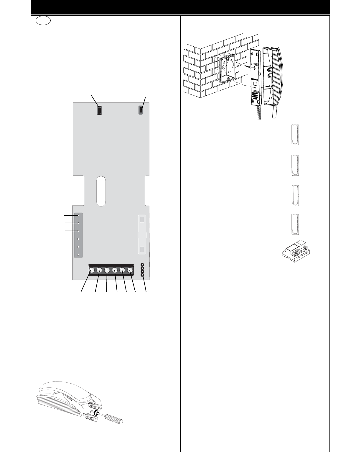
Fig. 5
B
A
A
A
I
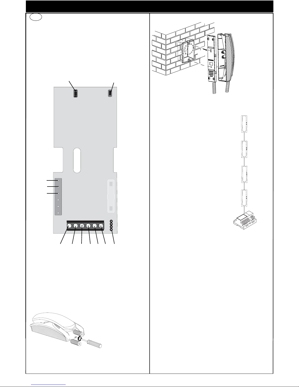
Fig. 2 Fissare la vite
superiore (A) nella
scatola incasso (o
tassello) lasciando
sporgere la testa
della vite per 2
mm. Agganciare il
citofono alla vite
superiore utilizzando l’apposito
foro posteriore
accostandolo alla
parete e tirandolo
verso il basso
Completare il fissaggio con la vite
inferiore (B) nell’apposito foro.
Fig. 1
Fig. 2
(A)
(B)
Fig. 1 Per separare il fondo del
citofono dal coperchio
inserire un cacciavite a
taglio nella fessura centrale e ruotarlo fino ad
ottenere lo scatto di apertura.
Reset
Attiv.
Stabilizzazione
segnale video
C
B
A
6P6S5421
A+
ACA
3
Programmazione codice identificativo
Il codice identificativo va programmato per mezzo di una targa (principale-MASTER), presente nell’impianto e già configurata.
Il citofono viene fornito senza codice identificativo assocciato. Per verificare ciò premere il pulsante serratura e il citofono emetterà un triplo
“Bip”.
Fase di programmazione:
1) Togliere il coperchio del citofono.
2) Premere e mantenere premuto il pulsante RESET presente nel citofono.
3) Premere e mantenere premuto la lamella corrispondente al pulsante serratura assieme al pulsante RESET.
4) Rilasciare il pulsante RESET, continuando a tenere premuto il pulsante serratura.
5) Dopo 2 secondi il citofono emette un tono acuto e viene messo in
comunicazione con la targa.
6) Rilasciare la lamella corrispondente alla serratura.
7) Nelle targhe a pulsanti premere il pulsante di chiamata corrispondente al citofono, invece nelle targhe alfanumeriche comporre il
codice di chiamata e premere il pulsante “ ”.
8) Se nell’impianto esiste già un citofono con lo stesso codice identificativo associato, la targa emette un segnale sonoro basso ed è
necessario ripetere l’operazione dal punto 2.
9) In caso contrario il codice viene associato al citofono e la comunicazione viene terminata.
Programmazione codice identificativo secondario
La programmazione del codice identificativo secondario è richiesto solamente quando si vuole far suonare contemporaneamente più di un citofono con lo stesso pulsante o codice di chiamata. I citofoni che devono
suonare contemporanemente vengono associati ad uno stesso gruppo.
Il citofono di “capogruppo” viene programmato per primo attraverso la
precedente procedura “programmazione codice identificativo”, invece i
citofoni aggiuntivi del gruppo vengono programmati con il codice identificativo secondario.
Il numero di citofoni che si possono associare ad uno stesso gruppo,
senza l’ausilio del programmatore art. 950C, sono 4.
Fase di programmazione:
1) Togliere il coperchio del citofono.
2) Premere e mantenere premuto il pulsante RESET presente nel citofono.
3) Premere e mantenere premuti la lamella corrispondente al pulsante serratura e il pulsante di autoinserimento (ATTIV. in alto a
destra), assieme al pulsante RESET.
4) Rilasciare il pulsante RESET, continuando a tenere premuti gli altri
2 pulsanti.
5) Dopo 2 secondi il citofono emette un tono acuto e viene messo in
comunicazione con la targa.
6) Rilasciare la lamella corrispondente alla serratura e il pulsante di
autoinserimento/autoaccensione.
7) Nelle targhe a pulsanti premere il pulsante di chiamata corrispondente al citofono di “capogruppo” (già programmato), invece nelle
targhe alfanumeriche comporre lo stesso codice di chiamata del
citofono di “capogruppo” e premere il pulsante “ ”.
8) Associato l’identificativo secondario al citofono, la comunicazione
viene terminata.
Programmazione pulsanti
Il citofono viene fornito con un pulsante per la funzione di servizio ausiliario “luce scale”, il quale attiva il 1° relè del 1° attuatore (art. 692R o
69RH), se collegato all’impianto.
Per cambiare il tipo di funzionamento del pulsante è necessario utilizzare il programmatore Art. 950C, ad eccezione della programmazione
come intercomunicante o per il servizio di autoaccensione verso una
targa specifica.
Se un pulsante è programmato ad una determinata funzione, il citofono
emette un “Click” quando viene premuto, altrimenti non emette nessun
segnale.
Programmazione pulsante per chiamata intercomunicante
Fase di programmazione:
1) Sganciare il microtelefono del citofono o videocitofono da
chiamare.
2) Togliere il coperchio del citofono da programmare.
PROGRAMMAZIONE/FUNZIONAMENTO
3) Premere e mantenere premuto il pulsante RESET presente nel citofono.
4) Premere e mantenere premuto il pulsante luce scale per eseguire la
chiamata intercomunicante assieme al pulsante RESET.
5) Rilasciare il pulsante RESET, continuando a tenere premuto il pulsante luce scale.
6) Dopo 2 secondi il citofono emette un tono acuto, mentre l’altro citofono emette una scala tritonale ascendente.
7) Rilasciare il pulsante luce scale.
8) Premere nel citofono chiamato (quello con il suono tritonale), uno
dei pulsanti programmati (come serratura o F1 o F2).
9) Un tono acuto conferma la fine della procedura.
Programmazione pulsante autoinserimento verso targa specifica.
Fase di programmazione:
1) Togliere il coperchio del citofono.
2) Premere e mantenere premuto il pulsante RESET presente nel citofono.
3) Premere e mantenere premuto il pulsante luce scale assieme al pulsante RESET
4) Rilasciare il pulsante RESET, continuando a tenere premuto il pulsante luce scale.
5) Dopo 2 secondi il citofono emette un tono acuto.
6) Rilasciare il pulsante relativo all’autoaccensione.
7) Nelle targhe a pulsanti premere il pulsante di chiamata corrispondente al citofono, invece nelle targhe alfanumeriche comporre il
codice di chiamata e premere il pulsante “ ”.
8) Un tono acuto conferma la fine della procedura.
Riprogrammazione valore di default dei pulsanti.
Fase di programmazione:
1) Togliere il coperchio del citofono.
2)
Premere e mantenere premuto il pulsante RESET presente nel citofono.
3) Premere e mantenere premuto il pulsante interessato da riprogrammare assieme al pulsante RESET.
4) Rilasciare il pulsante RESET, continuando a tenere premuto l’altro
pulsante.
5) Dopo 2 secondi il citofono emette un tono acuto.
6) Rilasciare il pulsante da riportare a default e ripremerlo.
Cancellazione totale delle programmazioni.
Fase di programmazione:
1) Togliere il coperchio del citofono.
2)
Premere e mantenere premuto il pulsante RESET presente nel citofono.
3) Premere e mantenere premuto il pulsante di autoaccensione (ATTIV.)
assieme al pulsante RESET.
4) Rilasciare il pulsante RESET, continuando a tenere premuto il pulsan-
te autoaccensione.
5) Dopo 2 secondi il citofono emette, per 2 secondi, un tono lungo.
6) Rilasciare il pulsante autoaccensione.
7) Durante il tono lungo, premere la lamella del pulsante serratura.
Se la procedura di cancellazione è andata a buon fine, premendo la
lamella della serratura il citofono emetterà un triplo “Bip”.
FUNZIONAMENTO
Le chiamate da targa esterna, intercomunicante e fuoriporta sono differenziate tra loro da toni diversi.
Chiamata da targa.
Le chiamate da targa non seguono la pressione del pulsante di chiamata ma vengono generate internamente dal citofono. Il periodo di chiamata è 1 secondo di suono e 2 secondi di pausa ripetuto per 2 volte (valore di default impostato nella targa). Per rispondere, sollevare il microtelefono. Se il microtelefono è già sollevato durante la chiamata riagganciare e risollevarlo. Il tempo di risposta alla chiamata (30 s) e il tempo di conversazione (2 minuti di default) sono impostati nei parametri della targa.
Scaduto il tempo di conversazione, si può continuare, senza riagganciare il microtelefono, se viene eseguita di nuovo la chiamata entro 10
secondi dalla stessa targa.
Chiamata intercomunicante.
Sollevare il microtelefono del citofono, premere il pulsante intercomunicante. Nel microtelefono del citofono chiamante si udrà un tono di chiamata (se la chiamata è possibile) o tono di occupato (se la chiamata non
è possibile). Nel citofono chiamato la suoneria inizierà a suonare ciclicamente con un ritmo di 1 secondo di suono e 4 secondi di pausa. La durata massima della chiamata sarà di 30 secondi (6 cicli). Per rispondere
alla chiamata è sufficiente sollevare il microtelefono; la durata massima
della conversazione è di 5 minuti. Scaduto il tempo di conversazione si
può continuare la conversazione, senza riagganciare il microtelefono, se
viene eseguita di nuovo la chiamata entro 10 secondi. Un’eventuale chiamata da targa ha priorità su quella intercomunicante.
4
INTRODUCTION/INSTALLATION
DESCRIPTION
Type 8879 is an interphone in the 8870 series for ELVOX 2-WIRE audio
and video door entry systems. It is supplied as standard with 2 pushbuttons, one for lock release, the other for stair light light (default).
Connection and connector terminal board
1, 2) BUS line.
4, 6P) Connection for door call pushbutton.
5, 6S) Connection of additional door ringtone
Controls
The call volume can be adjusted by moving the loudspeaker wire from
connector A+ (high) to A- (low).
INSTALLATION
Wall-mounted installations of the interphone do not require additional
accessories. However a vertical 3-module box may be used to facilitate
fixture and cable routing.
Surface wall-mounted intallation
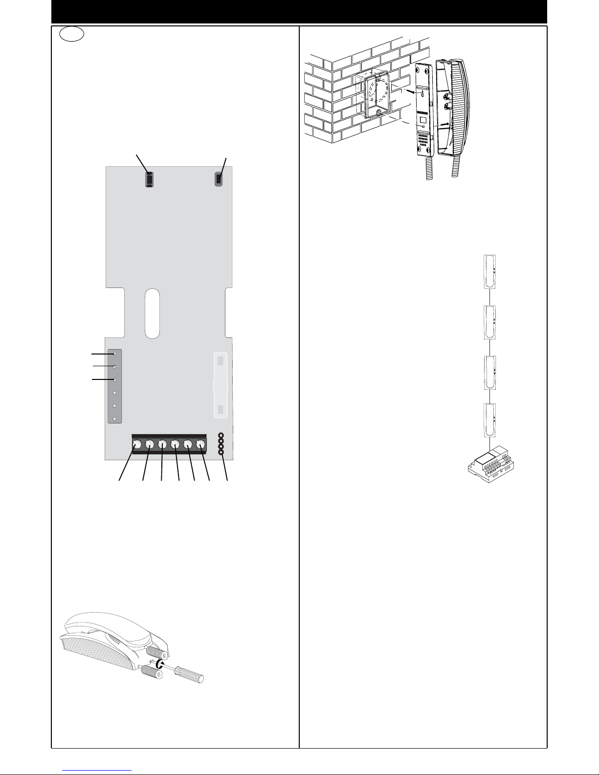
Video signal
stabiliser
GB
Reset
Activ.
C
B
A
6P6S5421
A+
A-
CA
Fig. 3 Fix the top screw (A) in the flush-mounted box (or wall plug), leaving the
screw head to protrude by 2 mm.
Hook the interphone onto the top screw using the appropriate hole in the
back, by placing it close to the wall and then pulling downwards
Complete mounting by screwing the bottom screw (B) into the appropriate hole.
Fig. 2
Fig. 3
(A)
(B)
Fig. 2 To separate the base of
the interphone from the
cover, insert a screwdriver in the slit in the middle and turn it until the
unit clicks open.
VIDEO SIGNAL STABILISATOR
On the lower side of the interphone there is a
connector (A-B-C) and a jumper for the video
signal balance. This jumper must be used on
the installations where there are more appliances (interphones or monitors) connected in
series (Fig. 5).
On the standard configuration displace the
jumper into "B" only on the last set and keep
the jumpers on the other appliances in the initial position "A" (No termination" (Fig. 5).
For other connection configurations see the:
TERMINATION TABLE FOR THE TWO WIRE
ELVOX INSTALLATIONS” shown on page 14
and concerning the wiring diagrams enclosed
with the electronic two wire entrance panels.
If the image shown on the monitor is distorted, displace the jumper into
one of the alternative positions to the initial one (B or C), so as to eliminate the distortion.
Fig. 5
B
A
A
A
Fig. 1
NOTE: in case of installations with only interphones, keep the jumpers in
“A” position.
PROGRAMMING
There are three interphone programming modes: assignment of an identification code or call code (indispensable), assignment of a secondary
identification code (for interphones associated with a master interphone),
programming of pushbuttons for auxiliary services and intercommunicating calls (when necessary).
5) Release the RESET pushbutton, keeping the stair light pushbutton
pressed.
6) After 2 seconds the interphone emits a high tone, while the other
interphone emits a 3-tone ascending scale.
7) Release the stair light pushbutton.
8) On the interphone called (with the 3-tone ring), press one of the programmed pushbuttons (such as lock release, F1 or F2).
9) A high tone confirms the end of the procedure.
Programming the self-start pushbutton to a specific panel.
Programming phase:
1) Remove the interphone cover.
2) Press and hold the RESET pushbutton on the interphone.
3) Press and hold the stair light pushbutton together with the RESET
pushbutton.
4) Release the RESET pushbutton, keeping the stair light pushbutton
pressed.
5) After 2 seconds the interphone emits a high tone.
6) Release the self start pushbutton.
7) On pushbutton entrance panels, press the call button for the inter-
phone, while on alphanumeric keypads, enter the call code and
press pushbutton “ ”.
8) A high tone confirms the end of the procedure.
Restoring default values of pushbutton.
Programming phase:
1) Remove the interphone cover.
2) Press and hold the RESET pushbutton on the interphone.
3) Press and hold the relative stair light pushbutton together with the
RESET pushbutton.
4) Release the RESET pushbutton, keeping
stair light push-button
pres-
sed.
5) After 2 seconds the interphone emits a high tone.
6) Release the stair light pushbutton and then press again.
Deleting all settings.
Programming phase:
1) Remove the interphone cover.
2) Press and hold the RESET pushbutton on the interphone.
3) Press and hold the self start pushbutton (ATTIV) together with the
RESET ATTIV. pushbutton.
4) Release the RESET pushbutton, keeping the self-start pushbutton
pressed.
5) After 2 seconds the interphone emits a continuous tone for two
seconds.
6) Release the self-start pushbutton.
7) During the continuous tone, press the tab on the lock release
pushbutton.
If the deletion procedure is successful, when the lock release tab is pressed the interphone emits a triple “Beep”.
OPERATION
Calls from an entrance panel, intercommunicating calls and door calls
are differentiated by means of different tones.
Door calls.
Calls from entrance panels do not follow the pressed pushbutton but are
generated inside the interphone. The call interval is 1 second of ringtone and 2 seconds of pause repeated twice (default value set on panel).
To answer, raise the handset. If the handset is already raised during the
call, replace and raise it again. The call answer time (30 s) and the conversation time (2 minutes by default) are set in the panel parameters.
When the conversation time has elapsed, the user can continue without
replacing the handset if a new call is made within 10 seconds from the
same panel.
Intercommunicating call.
Lift the handset and press the intercommunicating button for the interphone/monitor to be called. On the handset of the interphone called a
call tone will ring (if the call is enabled) or an engaged tone (if not enabled). On the called interphone the ringtone starts sequentially at intervals of 1 second ringing and 4 seconds pause. The maximum duration
of the call is 30 seconds (6 cycles). To answer the call, simply raise the
handset; the maximum duration of the conversation is 5 minutes. When
the conversation time has elapsed, the user can continue without replacing the handset if a new call is made within 10 seconds. Calls from the
panel have priority over intercommunicating calls.
Programming must be performed with the system switched on, without
active communication and only after connecting the interphones/monitors to the system and programming the panels.
Identification code programming
The identification code is programmed via an entrance panel (MASTER),
already configured and present on the system.
The interphone is supplied without associated identification code. To
verify this condition, press the lock release pushbutton and the interphone should emit a triple “Beep”.
Programming phase:
1) Remove the interphone cover.
2) Press and hold the RESET pushbutton on the interphone.
3) Press and hold the tab on the lock release pushbutton, together with
the RESET pushbutton.
4) Release the RESET pushbutton, keeping the lock release pushbutton pressed.
5) After 2 seconds the interphone emits a high tone and communication
is enabled with the panel.
6) Release the tab of the lock release pushbutton.
7) On pushbutton entrance panels, press the call button for the interphone, while on alphanumeric keypads, enter the call code and press
pushbutton “ ”.
8) If the system contains an interphone that already has the same associated identification code, the panel emits a low signal and the operation should be repeated from point 2.
9) Otherwise the code is associated with the interphone and communication is terminated.
Secondary identification code programming
Programming of the secondary identification code is only required when
more than one interphone is to be called by means of the same pushbutton or call code. The interphones that ring at the same time are associated with the same group. The “master” interphone is programmed first by
means of the “identification code programming” procedure described
above, while the additional group interphones are programmed with the
secondary identification code.
A maximum of four interphones can be associated with the same group,
without the need for programmer type 950C.
Programming phase:
1) Remove the interphone cover.
2) Press and hold the RESET pushbutton on the interphone.
3)
Press and hold the tab on the lock release pushbutton and the self
start/auto-activation (on top right hand side) pushbutton (Attiv-top on
the right hand side) together with the RESET pushbutton.
4) Release the RESET pushbutton, keeping the other two pushbuttons
pressed.
5) After 2 seconds the interphone emits a high tone and communication is enabled with the panel.
6) Release the tab on the lock release pushbutton and the self start
pushbutton.
7) On pushbutton entrance panels, press the call button for the
“master” interphone (already programmed), while on alphanumeric
keypads, enter the call code of the “master” interphone and press
pushbutton “ ”.
8) When the secondary code is associated with the interphone and
communication is terminated.
Pushbutton programming
The interphone is supplied with a pushbutton, for the functions auxiliary
service “stair light”, which activates the 1st relay of the 1st actuator (type
692R or 69RH).
To change the operating mode of push-button, use programmer type
950C, with the exception of the programming push-button as intercommunicating or for the self-start service associated with a specific panel.
If a pushbutton is programmed for a specific function, the interphone
emits a “Click” when pressed; otherwise it does not emit any signal.
Intercommunicating call pushbutton programming
Programming phase:
1) Raise
the handset of the interphone or monitor to be called.
2) Remove the cover of the interphone to be programmed.
3) Press and hold the RESET pushbutton on the interphone.
4) Press and hold the stair light pushbutton to make the intercommunicating call together with the RESET pushbutton.
PROGRAMMING/OPERATING
5
STABILISATEUR DU SIGNAL VIDÉO
Dans la partie inférieure du poste d'appartement il y a un connecteur (A-B-C) et un pontage pour la stabilisation du signal vidéo. Ce
pontage doit être utilisé dans les installation
avec plusieurs appareils (postes d'appartement ou moniteurs) raccordés en série (Fig. 5).
Dans la configuration de série déplacer le pontage sur la position «B» seulement dans le dernier appareil et maintenir les pontages des
autres appareils sur la position initiale «A»
(Aucune Termination).
Pour les autres configurations de raccordement voir la « TABLE TERMINATION POUR
INSTALLATIONS DE DEUX FILS ELVOX »
indiquée à page 14, les schémas de raccordement inclus avec les plaque de rue électroniques deux fils.
Si l'image dans le moniteur est déformé, déplacer le pontage sur une
des positions alternatives a celle initiale (B ou C), de façon a annuler la
déformation.
N.B. Si dans l’installation il ya seulement des postes d’appertement,
maintenir les pontages sur la position “A”.
Fig. 5
B
A
A
A
6
INTRODUCTION/INSTALLATION
DESCRIPTION
L'art. 8879 est un portier audio de la série 8870 pour systèmes de portiers audio ou vidéo 2 FILS ELVOX. Livré avec 2 boutons de série : un
pour la commande de la gâche, l’autre pour lumière sclalier (par défaut).
Bornier de connexion et connecteurs
1, 2) Ligne BUS.
4, 6P) Raccordement pour bouton-poussoir d'appel de palier
5, 6S) Raccordement sonnerie supplémentaire.
Réglages
Le volume d'appel est réglable en déplaçant le fil du haut-parleur entre
le connecteur A+ (ton haut) et A- (ton bas).
INSTALLATION
L'installation en saillie du portier audio ne nécessite pas d'accessoires
supplémentaires. Toutefois, il est possible de prévoir une boîte 3 modules verticale pour faciliter la fixation et le passage du câblage.
Installation murale en saillie
Stabilisateur de
signal vidéo
F
Reset
Activ.
C
B
A
6P6S5421
A+
ACA
Fig. 3 Fixer la vis supérieure (A) dans la
boîte à encastrement (ou cheville)
laissant sortir la
tête de vis de 2
mm. Accrocher le
portier à la vis
supérieure
en utilisant le trou
prévu à cet effet à
l'arrière en le
tenant contre la
paroi et le tirant
vers le bas.
Terminer la fixation
en logeant la vis
inférieure (B) dans
le trou prévu à cet
effet.
Fig. 2
Fig. 3
(A)
(B)
Fig. 2 Pour séparer le fond du
portier du couvercle en
introduisant un tournevis
à lame large dans la fente
centrale et le tourner
jusqu'à l'obtention du
déclic d'ouverture.
Fig. 1
PROGRAMMATION
Les programmations du portier audio sont de trois types: assignation
d'un code d'identification ou d'un code d'appel (indispensable), assignation d'un code d'identification secondaire (pour portiers audio associés à
un portier audio "Master"), programmation des boutons pour services
auxiliaires et la communication entre postes (lorsque cela est nécessaire). Les programmations doivent être effectuées avec le système allumé,
sans communication en cours et seulement après avoir relié les portiers
audio et/ou vidéo au système et programmé les plaques de rue.
 Loading...