


69RH
Manuale installatore - Installer guide
Manuel installateur - Technisches Handbuch
Instrucciones instalador - Manual do instalador
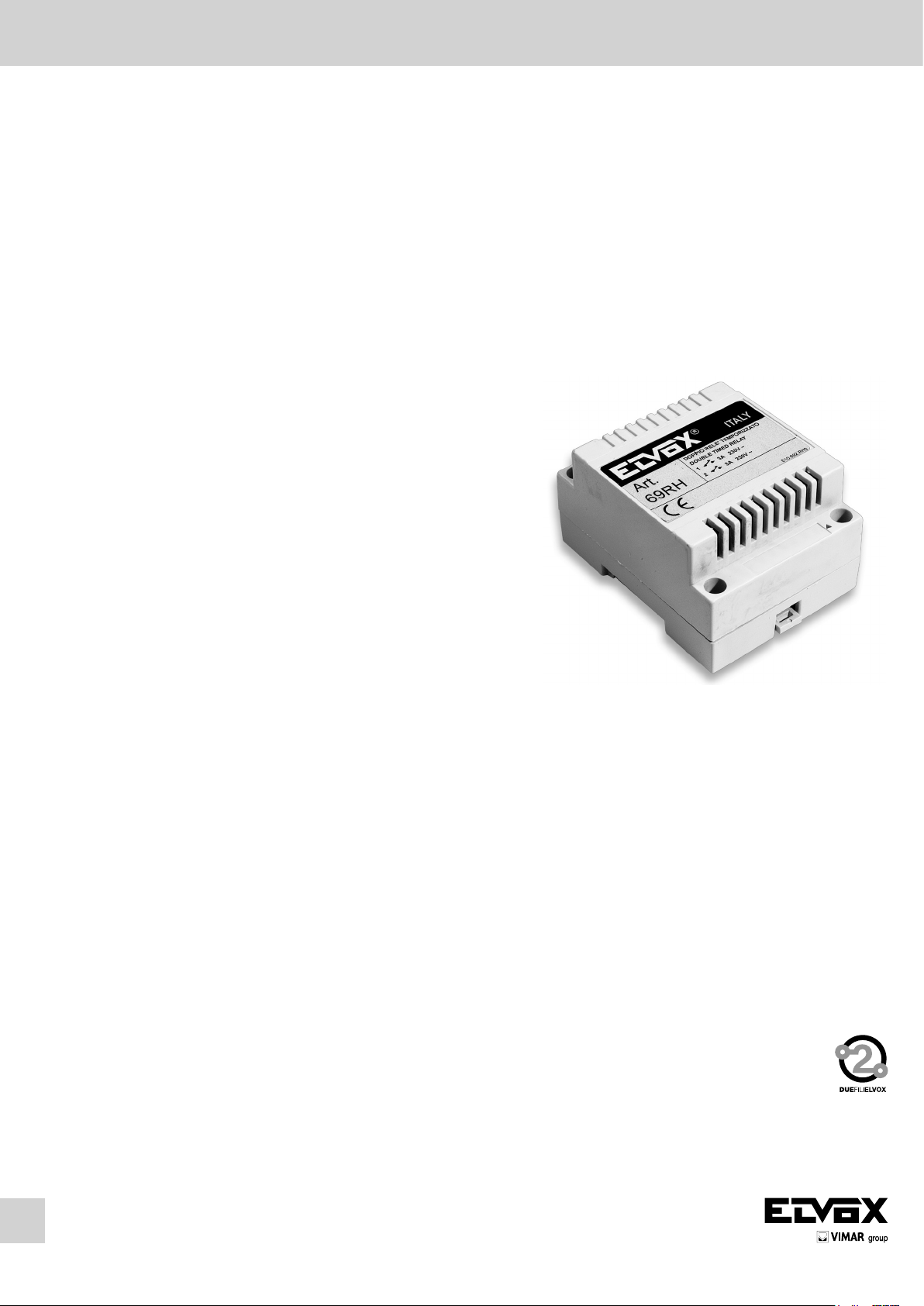
Art. 69RH
RELE’ PER FUNZIONI AUSILIARIE/RIPETITORE DI CHIAMATA PROGRAMMABILE PER SISTEMI DUE FILI ELVOX
RELAY FOR AUXILIARY FUNCTIONS/PROGRAMMABLE CALL REPEATER FOR ELVOX 2-WIRE SYSTEMS
RELAIS POUR FONCTIONS AUXILIAIRES / REPETITEUR D’APPEL PROGRAMMABLE POUR SYSTEMES DEUX FILS ELVOX
RELAIS FÜR ZUSATZFUNKTIONEN / PROGRAMMIERBARER RUFWIEDERHOLER FÜR ELVOX DUE FILI ANLAGEN
RELÉ PARA FUNCIONES AUXILIARES / REPETIDOR DE LLAMADA PROGRAMABLE PARA SISTEMAS DOS HILOS ELVOX
RELE’ PARA FUNÇÕES AUXILIARES / REPETIDOR DE CHAMADA PROGRAMÁVEL PARA SISTEMAS DOIS FIOS ELVOX

DESCRIZIONE
L’art. 69RH per impianti DUE FILI ELVOX è un dispositivo fornito di due relè con contatti normalmente aperti, che può svolgere due mansioni distinte a
seconda dell’impostazione che gli viene assegnata dall’utente eseguendo o meno una semplice programmazione. Le due modalità di funzionamento sono:
1. MODALITA’ RELÈ: relè per servizi ausiliari (non necessita alcuna programmazione)
2. MODALITA’ RIPETITORE: ripetitore di chiamata programmabile (previa programmazione)
Per riconoscere se il dispositivo sia stato programmato per lavorare in modalità ripetitore, oppure sia privo di programmazione e quindi è in modalità RELÈ,
basta osservare il LED luminoso posto sul circuito stampato all’accensione del dispositivo (vedi L1 figura 1):
LED SPENTO MODALITA’ RELÈ
LED LAMPEGGIANTE PER UN SECONDO MODALITA’ RIPETITORE
DESCRIZIONE MORSETTI E COMPONENTI D’INTERESSE (fig. 1)
1, 2, B1, B2) Linea BUS (due coppie di morsetti collegati in parallelo).
1A, 1B) 1° contatto normalmente aperto, carico massimo 3A 230Vca.
2A, 2B) 2° contatto normalmente aperto, carico massimo 3A 230Vca.
TEMPO ATTUAT. 1) Trimmer di regolazione tempo di attivazione 1° contatto (modalità RELÈ).
TEMPO ATTUAT. 2) Trimmer di regolazione tempo di attivazione 2° contatto (modalità RELÈ).
ID0-ID1-ID2) Ponticelli per identificazione dispositivo (modalità RELÈ) o per identificazione gruppi (modalità RIPETITORE).
S1) Pulsante per la programmazione/cancellazione gruppi (modalità RIPETITORE).
L1) LED per verifica modalità di lavoro e per programmazione/cancellazione gruppi (modalità RIPETITORE).
ABC) ponticelli per la terminazione del BUS.
MODALITA’ RELÈ
In questa modalità i due relè possono essere adibiti all’attivazione di due funzioni ausiliarie da ogni citofono e videocitofono con tecnologia DUE FILI ELVOX.
I contatti normalmente aperti sono indipendenti e possono essere temporizzati da 1 a 30 secondi, regolando i due trimmer posti sul circuito stampato (fig. 1)
ed indicati con le serigrafie “TEMPO ATTUAT. 1” e “TEMPO ATTUAT. 2”. Nello stesso impianto DUE FILI ELVOX si possono collegare fino ad 8 dispositivi
art. 69RH. Ciò significa che si può usufruire di un totale di 16 funzioni ausiliarie (due relè per ogni dispositivo 69RH). Quindi è necessario assegnare ad ogni
dispositivo 69RH un codice identificativo agendo sui ponticelli ID0-ID1-ID2 posti sul circuito stampato (fig. 1). Per l’assegnazione del codice identificativo
seguire la TAB.1
L’attivazione dei servizi ausiliari avviene dai citofoni e dai videocitofoni, quindi seguire le indicazioni riportate nelle istruzioni degli apparecchi alla voce 1° e
2° servizio ausiliario.
MODALITA’ RIPETITORE
In questa modalità il dispositivo ripetitore, abbinato ad una suoneria del tipo art. 860A o a timpano, permette la ripetizione della chiamata proveniente da targa
o da intercomunicante ed indirizzata ad uno o più gruppi citofonici o videocitofonici (fino ad un massimo di 4 gruppi). Il dispositivo utilizza due relè distinti
per la ripetizione di chiamate provenienti da targa e da intercomunicante, per cui è possibile distinguere le suonerie facendo gli opportuni collegamenti al
dispositivo suoneria (vedi schemi di collegamento).
PROGRAMMAZIONE DELLA MODALITA’ RIPETITORE
Per attivare questa modalità l’utente dovrà eseguire la seguente programmazione per impostare i gruppi di cui si intende ripetere la chiamata (fino ad un
massimo di 4 gruppi) .
La procedura per eseguire tale programmazione è la seguente:
1. LED inizialmente spento e ponticello su ID2 (vedi Tab. 1 e figura 2)
2. Posizionare gli altri due ponticelli in dotazione, su ID0 ed ID1 in modo da selezionare il gruppo di cui si intende ripetere la chiamata (vedi Tab. 1 e Fig. 2)
3. Tenere premuto il pulsante di programmazione per 2 secondi, fino all’accensione del LED, al fine di entrare in MODALITA’ DI PROGRAMMAZIONE.
4. A questo punto è necessario designare il capogruppo del gruppo selezionato al punto 2). A tal fine premere indifferentemente uno tra i pulsanti serratura,
attiva attuatore, F1, F2, dell’apparecchio citofonico/videocitofono che si vuole identificare come capogruppo. Alla ricezione del segnale dall’apparecchio
remoto, il LED passa da acceso a lampeggiante.
5. Per confermare la memorizzazione dell’indirizzo, premere il pulsante di programmazione. Il LED si spegne e la programmazione è conclusa.
6. Se si vuole impostare un altro gruppo chiamante, procedere come ai punti 2-5. Si possono selezionare fino ad un massimo di 4 gruppi.
NOTE
• Ilpunto4deveessereeffettuatoentro2minuti,altrimentiilsistemausciràautomaticamentedallamodalitàdiprogrammazione(ilLEDsispegne),senza
aver memorizzato il dato.
• Ilpunto5deveessereeffettuatoentro1minuto,altrimentiilsistemausciràautomaticamentedallamodalitàdiprogrammazione(ilLEDsispegne),senza
aver memorizzato il dato.
• Essendolaprogrammazioneasolascrittura,nonsaràpossibileconoscereicapigruppo.
CANCELLAZIONE DI UN GRUPPO
Un gruppo precedentemente programmato può essere cancellato nel seguente modo:
1. LED L1 inizialmente spento.
2. Togliere il ponticello da ID2 (fig. 1)
3. Posizionare gli altri due ponticelli in dotazione, su ID0 ed ID1 in modo da selezionare l’indirizzo del gruppo chiamante che si vuole eliminare (tab1 e fig.
2)
4. Tenere premuto il pulsante di programmazione per 2 secondi fino all’accensione del LED L1. Questo rimane acceso per un secondo, dopodiché si spegne
a conferma dell’avvenuta cancellazione.
5. Ripetere i punti 3 e 4 se si vuole cancellare altri gruppi precedentemente memorizzati.
RITORNO ALLA MODALITA’ RELÈ
Una volta che tutti i gruppi vengono cancellati secondo la procedura riportata nel capitolo precedente, il dispositivo torna in modalità relè. Per averne una
conferma, scollegare e ricollegare il dispositivo 69RH al BUS ed osservare lo stato del LED.
LED L1 SPENTO MODALITA’ RELÈ
LED L1 LAMPEGGIANTE PER UN SECONDO MODALITA’ RIPETITORE
2
IT

DESCRIPTION
Type 69RH for ELVOX 2-WIRE systems, is equipped with 2 relays with normally open contacts, which can perform two different tasks depending on the setting
by the user entered by means of a simple programming procedure. The two operating modes are:
1. RELAY MODE: relay for auxiliary services (no programming needed)
2. REPEATER MODE: programmable call repeater (programming required)
To identify whether the device has been set to repeater mode, or not programmed i.e. set to relay mode, simply check the indicator LED L1 on the printed
circuit board on activation of the device:
LED OFF RELAY MODE
LED FLASHING FOR ONE SECOND REPEATER MODE
DESCRIPTION OF TERMINALS AND COMPONENTS (fig. 1)
1, 2, B1, B2) BUS line (two pairs of terminals connected in parallel).
1A, 1B) 1st normally open contact, maximum load 3A 230Vac.
2A, 2B) 2nd normally open contact, maximum load 3A 230Vac.
ACTIV. TIME 1) Adjustment trimmer for activation time of 1st contact (RELAY mode).
ACTIV. TIME 2) Adjustment trimmer for activation time of 2nd contact (RELAY mode).
IDO-ID1-ID2) Jumpers for device identification (RELAY mode) or for group identification (REPEATER mode).
S1) Pushbutton for group programming/deletion (REPEATER mode).
L1) LED for checking operating status and for group programming/deletion (REPEATER mode).
ABC) jumpers for termination of BUS.
RELAY MODE
In this mode the two relays can be set for the activation of two auxiliary functions from each interphone and monitor using ELVOX 2-WIRE TECHNOLOGY.
The normally open contacts are independent and can be timed from 1 to 30 seconds, by adjusting the two trimmers on the printed circuit board (fig. 1) marked
with the texts “ACTIV. TIME 1” and “ACTIV. TIME 2”.
Up to 8 device types 69RH can be connected on the ELVOX 2-WIRE system. This means that a total of 16 auxiliary functions can be used (two relays for each
device type 69RH). Each device type 69RH must then be assigned with an identification code, by setting jumpers ID0-ID1-ID2 on the printed circuit board (fig.
1). To assign the identification codes, refer to TAB.1 fig. 2.
Activation of the auxiliary services is from the interphones and monitors, and therefore refer to the instructions of the appliances in the section on auxiliary
services 1 and 2.
REPEATER MODE
In this mode the device repeater, combined with a ringtone type 860A or chime, enables repetition of the call made from a panel or intercommunicating device
and addressed to one or more interphone or monitor groups (up to a maximum of 4 groups). The device uses two separate relays for the repetition of calls from
panels and intercom devices, and therefore the ringtones can be differentiated making the suitable connections to the ringtone device. (see wiring diagrams).
PROGRAMMING REPEATER MODE
To activate 692H mode, the following settings must be entered to set the groups for which call repetition is required (up to a maximum of 4 groups). The
programming procedure is as follows:
1. LED initially off and jumper on ID2.
2. Position the jumpers on ID0 and ID1 to select the group for call repetition (tab. 1 and fig. 2)
3. Press and hold the programming key for 2 seconds, until the LED turns on, to enter PROGRAMMING MODE.
4. At this point the master of the group selected in point 2 must be assigned. To do this, press any one of the lock pushbuttons to activate the operator F1,
F2, of the interphone/monitor to be assigned as group master. On reception of the signal by the remote device, the LED changes to flashing status.
5. To confirm memorisation of the address, pres the programming key. The LED turns off and programming is complete.
6. To set another call group, proceed as described in points 2-5. A maximum of 4 groups can be selected as required.
NOTES
• Point4mustbecompletedwithinanintervalof2minutes;otherwisethesystemautomaticallyexitsprogrammingmode(theLEDturnsoff),withoutmemorising the data.
• Point5mustbecompletedwithinanintervalof1minute;otherwisethesystemautomaticallyexitsprogrammingmode(theLEDturnsoff),withoutmemorising the data.
• Asprogrammingiswrite-only,thegroupmasterscannotbeidentified.
DELETING A GROUP
A previously programmed group can be deleted as follows:
1. LED L1 initially off.
2. Remove the jumper from ID2 (fig. 1)
3. Position the jumpers ID0 and ID1 to enable selection of the call group address to be deleted (tab1 and fig. 2)
4. Press and hold the programming key for 2 seconds, until the LED L1 turns on. This remains lit for one second, after which it turns off to confirm deletion.
5. Repeat points 3 and 4 to delete other previously memorised groups as required.
RETURN TO RELAY MODE
Once all groups have been deleted according to the procedure described in the previous chapter, the device returns to 692R mode. For confirmation, disconnect and reconnect the device 69RH to the BUS and check the status of the LED.
LED L1 OFF RELAY MODE
LED FLASHING FOR ONE SECOND REPEATER MODE
EN
3
DESCRIPTION
L’art. 69RH pour installations DEUX FILS ELVOX est un dispositif équipé de deux relais avec contacts normalement ouverts, qui peut exercer deux fonctions
distinctes selon la formulation qui lui est attribuée par l’utilisateur, en réalisant ou non une simple programmation. Les deux modalités de fonctionnement sont :
1. MODALITE RELAIS: relais pour services auxiliaires (ne nécessite aucune programmation)
2. MODALITE RÉPÉTITEUR: répétiteur d’appel programmable (après programmation)
Pour savoir si le dispositif a été programmé pour fonctionner en modalité répétiteur, ou bien s’il est exempt de programmation et donc en modalité relais, il
suffit de regarder la LED lumineuse L1 située sur le circuit imprimé à l’allumage du dispositif :
LED ETEINTE MODALITE RELAIS
LED CLIGNOTANTE PENDANT UNE SECONDE MODALITE RÉPÉTITEUR
DESCRIPTION BORNES ET COMPOSANTS D’INTERET (fig. 1)
1, 2, B1, B2) Ligne BUS (deux couples de bornes reliées en parallèle).
1A, 1B) 1er contact normalement ouvert, charge maximum 3A 230Vca.
2A, 2B) 2ème contact normalement ouvert, charge maximum 3A 230Vca.
TEMPS ACTION. 1) Trimmer de réglage temps d’activation 1er contact (modalité RELAIS).
TEMPS ACTION. 2) Trimmer de réglage temps d’activation 2ème contact (modalité RELAIS).
IDO-ID1-ID2) Pontets pour identification dispositif (modalité RELAIS) ou pour identification groupes (modalité RÉPÉTITEUR).
S1) Bouton pour la programmation/effacement groupes (modalité RÉPÉTITEUR).
L1) LED pour la vérification modalité de travail et pour la programmation/effacement groupes (modalité RÉPÉTITEUR).
ABC) pontets pour la terminaison du BUS.
MODALITE RELAIS
Dans cette modalité, les deux relais peuvent être destinés à l’activation de deux fonctions auxiliaires depuis chaque portier et vidéo-portier avec technologie
DEUX FILS ELVOX. Les contacts normalement ouverts sont indépendants et peuvent être temporisés de 1 à 30 secondes, en réglant les deux trimmers
situés sur le circuit imprimé (fig. 1) et indiqués avec les sérigraphies “temps action. 1” et “temps action. 2”.
Dans la même installation DEUX FILS ELVOX, il est possible de relier jusqu’à 8 dispositifs art. 69RH. Cela signifie que l’on peut bénéficier d’un total de 16
fonctions auxiliaires (deux relais pour chaque dispositif 69RH). Il est donc nécessaire d’attribuer à chaque dispositif 69RH un code d’identification en agissant
sur les pontets ID0-ID1-ID2 situés sur le circuit imprimé (fig. 1). Pour l’attribution du code d’identification, voir la TAB.1..
L’activationdesservicesauxiliairess’effectuedepuislesportiersetlesportiersvidéo;parconséquent,suivrelesindicationsprésentesdanslesinstructions
des appareils au poste 1er et 2ème service auxiliaire.
MODALITE RÉPÉTITEUR
Dans cette modalité, le dispositif 69RH, associé à une sonnerie de type art. 860A ou à tympan, permet la répétition de l’appel provenant de la plaque ou
de l’interphone et adressé à un ou plusieurs groupes portiers ou portiers vidéo (jusqu’à un maximum de 4 groupes). Le dispositif utilise deux relais distincts
pourlarépétitiond’appelsprovenant deplaqueet d’interphone;parconséquent,ilestpossibledereconnaîtrelessonneries enréalisantles connexions
opportunes au dispositif sonnerie (voir schémas de connexion).
PROGRAMMATION DE LA MODALITE RÉPÉTITEUR
Pour activer la modalité répétiteur, l’utilisateur devra réaliser la programmation suivante afin d’introduire les groupes dont il désire répéter l’appel (jusqu’à
un maximum de 4 groupes) .
La procédure pour réaliser cette programmation est la suivante :
1. LED initialement éteinte et pontet sur ID2.
2. Positionner les pontets sur ID0 et ID1 pour sélectionner le groupe dont on désire répéter l’appel (TAB. 1 et fig. 2)
3. Maintenir le bouton de programmation appuyé pendant 2 secondes, jusqu’à l’allumage de la LED, afin d’entrer en MODALITE DE PROGRAMMATION.
4. A ce stade, il est nécessaire de désigner le chef de groupe du groupe sélectionné au point 2). A cet effet, appuyer indifféremment sur l’un des boutons
“serrure”, “activer actionneur”, “F1”, “F2”, de l’appareil portier/portier vidéo que l’on veut identifier comme chef de groupe. A la réception du signal depuis
l’appareil à distance, la LED passera de “allumée” à “clignotante”.
5. Pour confirmer la mémorisation de l’adresse, appuyer sur le bouton de programmation. La LED s’éteint et la programmation est terminée.
6. Si l’on veut introduire un autre groupe d’appel, procéder comme aux points 2-5. On peut sélectionner jusqu’à un maximum de 4 groupes.
REMARQUE
• Lepoint4doitêtreeffectuédansles2minutesquisuivent,sinonlesystèmesortautomatiquementdelamodalitédeprogrammation(laLEDs’éteint)
sans avoir mémorisé la donnée.
• Lepoint5doitêtreeffectuédanslaminutequisuit,sinonlesystèmesortautomatiquementdelamodalitédeprogrammation(laLEDs’éteint)sansavoir
mémorisé la donnée.
• Laprogrammationétantd’écritureseulement,ilneserapaspossibledeconnaîtreleschefsdegroupe.
EFFACEMENT D’UN GROUPE
Un groupe précédemment programmé peut être effacé de la manière suivante:
1. LED L1 initialement éteinte.
2. Enlever le pontet de ID2 (fig. 1)
3. Positionner les pontets ID0 et ID1 de manière à sélectionner l’adresse du groupe d’appel que l’on désire éliminer (TAB. 1 et fig. 2)
4. Maintenir le bouton de programmation enfoncé pendant 2 secondes jusqu’à l’allumage de la LED L1. Elle reste allumée pendant une seconde puis elle
s’éteint pour confirmer que l’effacement a été effectué.
5. Répéter les points 3 et 4 si l’on désire effacer d’autres groupes précédemment mémorisés.
RETOUR A LA MODALITE RELAIS
Lorsque tous les groupes sont effacés selon la procédure indiquée dans le chapitre précédent, le dispositif retourne en modalité 692R. Pour en avoir une
confirmation, déconnecter et reconnecter le dispositif 69RH au BUS et observer l’état de la LED.
LED L1 ETEINTE MODALITE RELAIS
LED L1 CLIGNOTANTE PENDANT UNE SECONDE MODALITE REPETITEUR
4
FR
BESCHREIBUNG
Der Art. 69RH für ELVOX DUE FILI Anlagen ist eine Vorrichtung mit zwei Relais mit Schließerkontakten, die je nachdem, ob der Benutzer eine einfache
Programmierung durchführt oder nicht, zwei verschiedene Funktionen erfüllen kann. Die zwei Funktionsmöglichkeiten sind:
1. FUNKTIONSMODUS RELAIS: Relais für Zusatzfunktionen (erfordert keine Programmierung)
2. FUNKTIONSMODUS RUFWIEDERHOLER: Programmierbarer Rufwiederholer (nach Programmierung)
Um zu erkennen, ob die Vorrichtung auf den Funktionsmodus Rufwiederholer programmiert wurde, oder keine Programmierung stattgefunden hat und sich
die Vorrichtung daher im Funktionsmodus RELAIS befindet, genügt ein Blick auf die LED L1 auf der Leiterplatte bei Einschalten der Vorrichtung:
LED AUSGESCHALTET FUNKTIONSMODUS RELAIS
LED BLINKT EINE SEKUNDE LANG FUNKTIONSMODUS RUFWIEDERHOLER
BESCHREIBUNG DER KLEMMEN UND DER RELEVANTEN BAUTEILE (Abb. 1)
1, 2, B1, B2) BUS-Leitung (zwei Paar parallelgeschaltete Klemmen).
1A, 1B) 1. Schließerkontakt, max. Kontaktbelastung 3A 230 VAC
2A, 2B) 2. Schließerkontakt, max. Kontaktbelastung 3A 230VAC
AKTIVIERUNGSZEIT 1) Trimmer zur Einstellung der Aktivierungszeit des 1. Kontakts (Funktionsmodus RELAIS).
AKTIVIERUNGSZEIT 2) Trimmer zur Einstellung der Aktivierungszeit des 2. Kontakts (Funktionsmodus RELAIS).
IDO-ID1-ID2) Steckbrücken zur Identifizierung der Vorrichtung (Funktionsmodus Relais) oder zur Identifizierung von Gruppen (Funktionsmodus Rufwie-
derholer).
S1) Taste für die Programmierung/Löschung von Gruppen (Funktionsmodus Rufwiederholer).
L1) LED zur Kontrolle des Funktionsmodus und der Programmierung/Löschung von Gruppen (Funktionsmodus Rufwiederholer). ABC) Steckbrücken für
den Busabschluss.
FUNKTIONSMODUS RELAIS
In diesem Funktionsmodus können die zwei Relais zur Aktivierung von zwei Zusatzfunktionen von jedem ELVOX DUE FILI Haustelefon und Videohaustelefon
bestimmt werden. Die Schließerkontakte sind unabhängig und können durch Einstellen der zwei Trimmer auf der Leiterplatte (Abb. 1), die mit dem Aufdruck
“Tempo Attuat. 1” und “Tempo Attuat. 2” gekennzeichnet sind, von 1 bis 30 Sekunden zeitgesteuert werden. In einer ELVOX DUE FILI Anlage können bis zu
8 Vorrichtungen Art. 69RH angeschlossen werden. Dies bedeutet, dass insgesamt 16 Zusatzfunktionen zur Verfügung stehen (zwei Relais pro Vorrichtung
69RH). Jeder Vorrichtung 69RH muss deshalb durch Verstellen der Steckbrücken ID0-ID1-ID2 auf der Leiterplatte (Abb. 1) ein Kenncode zugewiesen werden. Für die Zuweisung des Kenncodes siehe Tab. 1. Die Aktivierung der Zusatzfunktionen erfolgt von den Haustelefonen und von den Videohaustelefonen,
daher sind die Anleitungen der Geräte im Kapitel 1. und 2. Zusatzfunktion zu befolgen.
FUNKTIONSMODUS RUFWIEDERHOLER
In diesem Funktionsmodus gestattet die mit einem Läutwerk vom Typ Art. 860A oder mit einer Klingel kombinierte Vorrichtung Art. 69RH die Wiederholung
des vom Klingeltableau kommenden Rufs oder des internen Rufs, der an eine oder mehrere Haustelefon- oder Videohaustelefongruppen gerichtet ist (bis zu
maximal 4 Gruppen). Die Vorrichtung verwendet zwei verschiedene Relais für die Wiederholung der Rufe vom Klingeltableau und der internen Rufe, deshalb
können die Klingeltöne durch Ausführung der entsprechenden Anschlüssen am Läutwerk unterschieden werden (siehe Anschlusspläne).
PROGRAMMIERUNG DES FUNKTIONSMODUS RUFWIEDERHOLER
Um den Funktionsmodus Rufwiederholer zu aktivieren, muss der Benutzer die folgende Programmierung durchführen, um die Gruppen, deren Rufe wiederholt werden sollen, einzustellen (bis zu maximal 4 Gruppen) . Für diese Programmierung muss die folgende Prozedur durchgeführt werden:
1. LED zunächst ausgeschaltet und Steckbrücke auf ID2.
2. Die Steckbrücken auf ID0 und ID1 setzen, um die Gruppe zu wählen, deren Ruf wiederholt werden soll (TAB 1, und Abb. 2)
3.
Die Programmierungstaste 2 Sekunden lang gedrückt halten, bis die LED aufleuchtet, um den PROGRAMMIERUNGSMODUS zu öffnen.
4. Nun muss das Hauptgerät der unter Punkt 2) gewählten Gruppe zugewiesen werden. Dazu muss entweder die Taste Türöffner, F1 oder F2, des Haustelefons/Videohaustelefons gedrückt werden, das als Hauptgerät der Gruppe identifiziert werden soll. Bei Empfang des Signals vom Gerät schaltet die
LED von Dauer- auf Blinklicht.
5. Um die Speicherung der Adresse zu bestätigen, die Programmiertaste drücken. Die LED erlischt und die Programmierung ist abgeschlossen.
6. Wenn eine weitere Rufgruppe eingerichtet werden soll, muss man wie in Punkt 2 bis 5 beschrieben, vorgehen. Es können maximal 4 Gruppen gewählt
werden.
HINWEISE
• Punkt4mussinnerhalbvon2Minutenausgeführtwerden,sonstverlässtdasSystemautomatischdenProgrammiermodus(dieLEDerlischt),ohneden
Wert gespeichert zu haben.
• Punkt5mussinnerhalbvon1Minuteausgeführtwerden,sonstverlässtdasSystemautomatischdenProgrammiermodus(dieLEDerlischt),ohneden
Wert gespeichert zu haben.
• DadieProgrammierungeinereineSchreibfunktionist,sinddieHauptgerätenichtzuerkennen.
LÖSCHEN EINER GRUPPE
Eine zuvor programmierte Gruppe kann folgendermaßen gelöscht werden:
1. LED L1 zunächst ausgeschaltet.
2. Die Steckbrücke von ID2 (Abb. 1) entfernen.
3. Die Steckbrücken ID0 und ID1 so setzen, dass die Adresse der Rufgruppe, die gelöscht werden soll, gewählt wird (TAB1 und Abb. 2).
4. Die Programmiertaste 2 Sekunden lang gedrückt halten, bis die LED L1 aufleuchtet. Diese LED bleibt eine Sekunden lang eingeschaltet, ihr Erlöschen
bestätigt die erfolgreiche Löschung der Gruppe.
5. Die Punkte 3 und 4 wiederholen, wenn andere zuvor gespeicherte Gruppen gelöscht werden sollen.
RÜCKKEHR ZUM FUNKTIONSMODUS RELAIS
Wenn alle Gruppen mit der oben beschriebenen Prozedur gelöscht werden, kehrt die Vorrichtung zum Funktionsmodus RELAIS zurück. Um den Funktionsmodus zu überprüfen, die Vorrichtung Art. 69RH vom Bus trennen und wieder anschließen, und den Zustand der LED kontrollieren.
LED L1 AUSGESCHALTET FUNKTIONSMODUS RELAIS
LED L1 BLINKT EINE SEKUNDE LANG FUNKTIONSMODUS RUFWIEDERHOLER
DE
5
 Loading...