


FIELDVISION
OCM-7P-HDR
7" Professional Field Monitor
QUICKSTART
GUIDE

PRECAUTIONS
• Exposure to high sound levels
can cause permanent hearing
loss. Avoid listening at high
volumes for extended periods
of time.
• Keep this product away from
water and any ammable
gases or liquids.
• Do not expose this product
to humidity or extreme heat
or cold.
• Make sure this product is
powered off when plugging it
into a power source.
• Use only the correct,
recommended voltage.
• Do not attempt to disassemble
or repair this product.
• Do not place or store the
monitor facedown, since this
can damage the screen.
2
• Handle this product with care.
Avoid any impacts to this
product.
• Do not block the vents in this
product.
• Disconnect this product from
its power source before storage
and during electrical storms.
• Do not use chemical solutions
to clean this product. Clean it
with only a soft, dry cloth.
• Keep this product away from
children.
• Make sure that this product
is intact and that there are no
missing parts.
• To avoid damage to this
product, be careful not to
overtighten or improperly
thread any of the threaded
ttings.
• All images are for illustrative
purposes only.
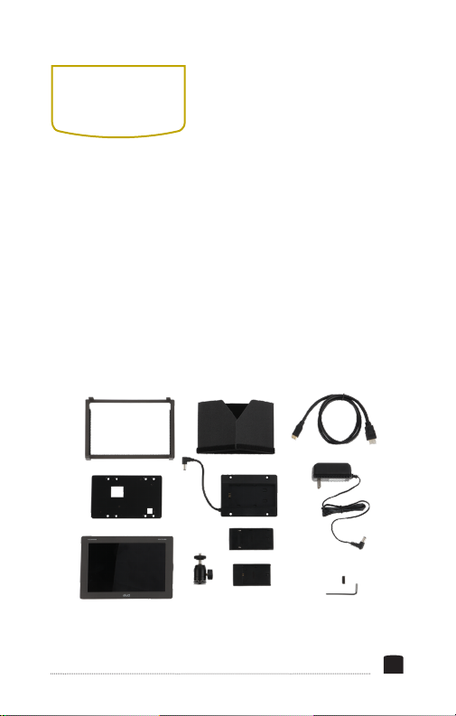
BOX
CONTENTS
• Monitor
• Sun hood
• Sun-hood frame
• Mini HDMI to HDMI cable
(C to A)
• Shoe-mount ball head
• Battery adapter and
mounting screws
• NP-F battery plate
• LP-E6 battery plate
• V-mount battery adapter
and mounting screws
• 1/4-20 screw and hex key
• 12 V DC power supply
3
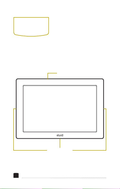
OVERVIEW
Heat vents
FIELDVISION OCM-7P-HDR
1/4-20 threaded
mounting sockets
4
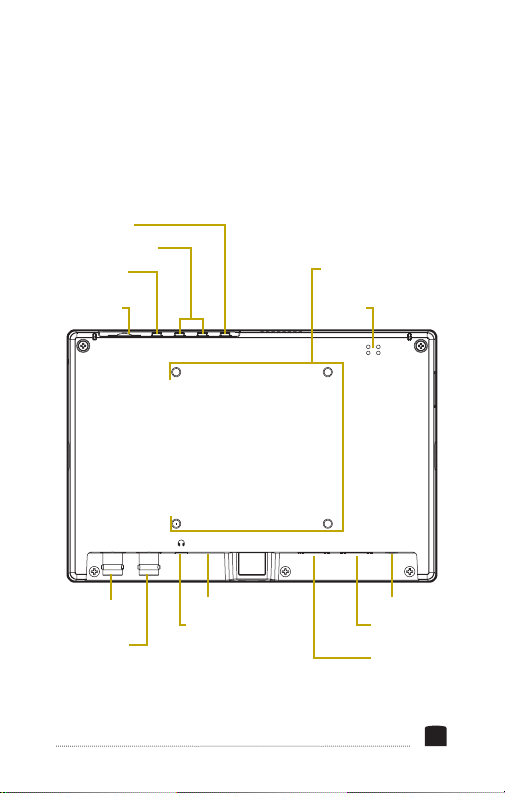
Input selector
F1 and F2 buttons
Exit button /
mute button
Scroll wheel
MENU EXIT F1 F2 INPUT
IN
SDI OUT USB OUT HDMI IN DC 12V
Battery plate
mounting holes
Speaker
SDI input
connector
SDI output
connector
USB port
Headphone
jack
Power input
HDMI input
connector
HDMI output
connector
5
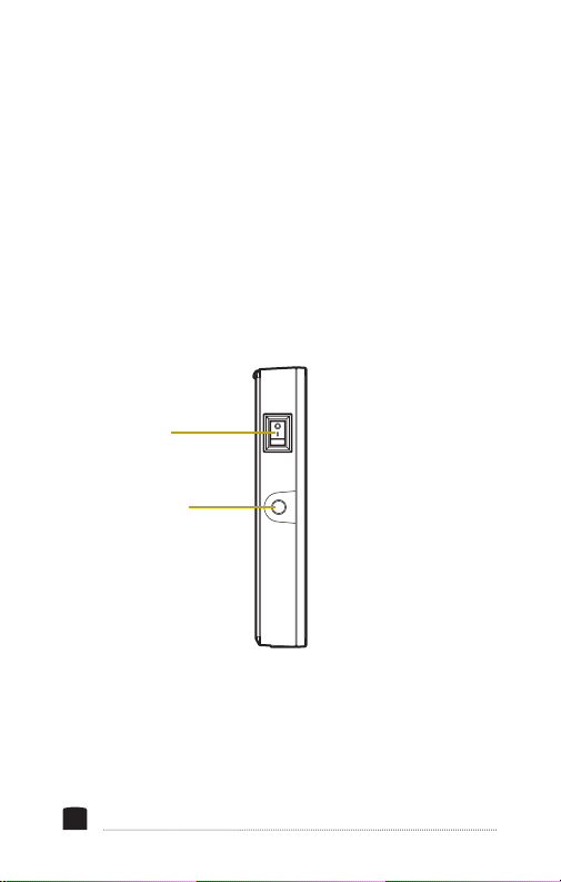
Power switch
1/4-20 threaded
mounting socket
6
OFF
ON
GETTING
STARTED
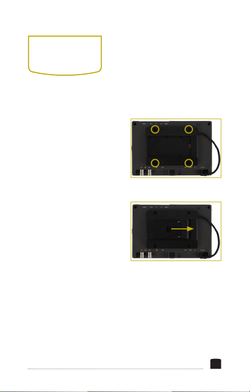
ATTACHING A BATTERY PLATE
1. Align the battery adapter
with the four mounting
holes on the back of the
monitor, and screw it in
with the included screws.
2. Attach the power cord to
the power input.
3. Place the NP-F or LP-E6
battery plate into the
adapter, making sure
to align the plate’s and
adapter’s contacts. Slide
the battery plate into the
adapter until it locks in place.
INSTALLING THE BATTERY
1. Place an NP-F or LP-E6 type battery into the battery plate,
making sure the plate’s contacts align with the battery
terminals.
7
2. Slide the battery toward the contacts until it’s rmly in
place.
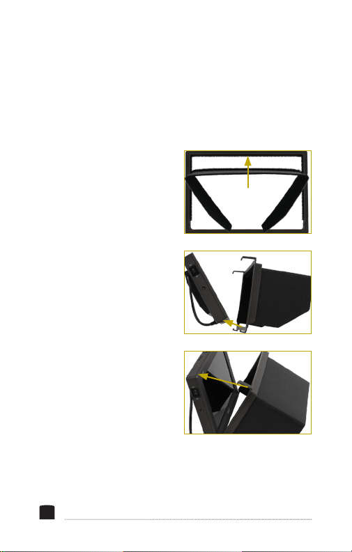
ATTACHING THE SUN HOOD
Attach the sun hood to the monitor by following these steps:
1. Attach the sun hood to
the sun-hood frame by
pressing the touchconnect strips together.
2. Attach the frame and the
sun hood to the monitor
by hooking the short
clips to the bottom of the
monitor.
3. Gently push up on the
long clips, and slide
them over the top of the
monitor until they click
into place.
8

MOUNTING THE MONITOR ONTO A CAMERA
1. Determine the monitor orientation you prefer, and screw
the ballhead into the bottom or side 1/4-20 threaded socket
until it’s tight.
2. Loosen the mounting foot by turning the locking wheel
clockwise. Make sure the side tilt adjustment knob is tight,
and the ballhead is locked in place.
3. Fully insert the foot into the camera’s shoe, and tighten the
locking wheel by turning it counterclockwise until secure.
4. Adjust the monitor angle by holding onto it while loosening
the adjustment knob. Change the monitor’s position, and
tighten the tilt adjustment knob until the monitor does not
slip.
MOUNTING THE MONITOR TO A CAMERA RIG
To mount the ballhead directly to an accessory with 1/4-20
mounting sockets, like a shoulder rig or slider, follow these
steps:
1. Tighten the ballhead’s tilt
adjustment knob, and then
remove the mounting foot
by unscrewing it.
9

2. Screw the 1/4-20 screw
into the socket, and
tighten it with the hex key.
3. Screw the ballhead into
a 1/4-20 socket until it’s
snug.
4. Screw the monitor onto the ballhead, and secure it by
tightening the locking wheel.
CONNECTING TO A CAMERA
HDMI: Connect the monitor’s HDMI input to a camera with an
HDMI output.
SDI: Connect the monitor’s SDI input to a camcorder or camera
with an SDI output.
OUTPUTTING THE SIGNAL
Use the HDMI and SDI output to send the signal to a monitor
or recorder.
POWERING ON
1. Connect a battery or DC power source.
2. Switch the power switch to the on position.
10

USER
INTERFACE
ACCESSING THE MENUS
To get the most out of the monitor, make sure its settings are
properly congured. All the setting congurations are located
in the main menu, which has six submenus: Image Adjust,
Marker, Function, Monitoring Tools, Audio, and System.
MENU NAVIGATION
1. Press the scroll wheel to enter the main menu, and turn the
wheel to scroll through menus and settings.
2. Press the scroll wheel to enter menus and conrm settings.
3. Press the exit button to return to the previous menu and to
exit the menu navigation from the top menu.
11

QUICK ADJUSTMENTS
When the monitor is powered on, you can make quick
adjustments to the volume, brightness, contrast, saturation,
and sharpness settings at any time.
• Turn the scroll wheel to activate the volume menu and
change the volume.
• While the volume menu is on-screen, press the scroll
wheel repeatedly to cycle through the brightness, contrast,
saturation, and sharpness menus, and to exit quick adjust
mode.
• The Exit button controls the audio mute. Press to quickly
mute the audio. Press again to unmute.
• The Input button toggles the input signal selector. Press the
button to switch between HDMI and SDI input signals.
FUNCTION BUTTONS
The two user-denable function buttons (F1 and F2) on
the top of the monitor engage monitor functions that can
be programmed to accommodate your specic needs. See
Function Button Setup
below for information on changing the
function assignment for each button.
By default, F1 is set to Scan, and F2 is set to Waveform.
12

When activated, the function buttons default to the setting in
the Scan and Waveform menus described below.
Press the function button repeatedly to cycle through the
options available in the menu's settings.
• Press the function button to activate the menu.
• Press the function button repeatedly to change the setting.
• Press exit to exit the menu, or the menu will automatically
close in 5 seconds.
FUNCTION BUTTON SETUP
To change the functions assigned to the F1 and F2 buttons,
follow these steps:
1. Press and hold the function button until the function select
menu appears on-screen.
2. Turn the scroll wheel to move through the options until you
arrive at the desired function, and press the scroll wheel to
save it and return to the main view.
Menu options for the function buttons are Center Marker,
Aspect Marker, Check Field, Underscan, Scan, Aspect, DSLR,
Freeze, H/V Delay, Peaking, False Color, Exposure, Histogram,
Level Meter, Waveform, and Timecode.
13

RESETTING THE OCM-7P-HDR
To erase all settings and return to the factory presets, follow
these steps:
1. Press the scroll wheel to open the main menu.
2. Select System.
3. In the System menu, scroll down to Reset, and press the
scroll wheel.
4. If you’re ready to reset the monitor, use the scroll wheel to
select On and push the scroll wheel to conrm. The monitor
takes a few seconds to reset and return to the main view.
14

IMAGE
ADJUST MENU
BRIGHTNESS
Adjusts the monitor’s brightness value from 0 to 100. The
default setting is 50.
CONTRAST
Adjusts the contrast value of the on-screen image from 0 to
100. The default setting is 50.
SATURATION
Adjusts the value of screen color saturation from 0 to 100. The
default setting is 50.
TINT
Adjusts the tint value from 0 to 100. The default setting is 50.
SHARPNESS
Adjusts the value of ne detail of the picture from 0 to 100.
The default setting is 0.
15

HDMI RGB RANGE
Select limited range 16–235 (default) or full range 0–255.
COLOR SPACE
Selects one of the color-space presets: Rec709 (default), EBU,
Native, and SMPTE-C.
CAMERA LUT
Activates either the Default LUT menu or the user LUT
menu. The default setting is off. Applied LUTs will be sent
downstream on active outputs.
DEFAULT LUT
Available only when Def. LUT is selected in the Camera LUT
menu. When activated, select from the list of LUTs that are
built into the monitor. Select from SLog2ToLC-709 (default),
SLog2ToLC-709TA, SLog2ToSLog2-709, SLog2ToCine+709,
SLog3ToLC-709, SLog3ToLC-709TA, SLog3ToSLog2-709, or
SLog3ToCine+709.
USER LUT
Available only when User LUT is selected in the Camera LUT
menu. When activated, select from user-supplied LUTs that
can be accessed via the USB port. The User LUT menu shows
No Data until user LUTs have been loaded via USB.
16

GAMMA
Select one of the preset gamma points. Choose Off, 1.8, 2.0,
2.2 (default), 2.35, 2.4, 2.6, or 2.8.
HDR
Select one of the HDR presets. Choose Off (default), ST 2084
300, ST 2084 1000, ST 2084 10000, or HIg.
BACK LIGHT MODE
Adjusts the intensity of the backlight. Options are Outdoor,
Standard (default), and Custom.
BACK LIGHT
When Custom is selected in the Backlight Mode menu, the
backlight intensity can be set manually from 0 to 100.
COLOR TEMP
Adjusts the color temperature of the on-screen image. Presets
are 5500, 5600, 6500 (default), 7500, 9300, and User. When
User mode is selected, the values of red, green, and blue gain
can be set manually from 0 to 255 and are preset to 128. Red,
green, and blue offset can be set manually from 0 to 511 and
are preset to 255.
17

MARKER
MENU
CENTER MARKER
Turning the center marker option on places a crosshair at the
center of the screen. The preset is set to off.
ASPECT MARKER
Sets the aspect marker on-screen display. Select from 16:9,
1.85:1, 2.35:1, 4:3, 3:2, 1.3X, 2.0X, 2.0X MAG, and off (default).
SAFETY MARKER
Displays an on-screen safety frame marker. Select from 95%,
93%, 90%, 88%, 85%, 80%, and off (default).
MARKER COLOR
Changes the color of the on-screen markers. Choose from color
options red (default), green, blue, white, and black.
18

MARKER MAT
Available only when an aspect ratio is selected from the
Aspect Marker menu. Adjust the darkness of the area of
the screen that’s outside the aspect marker. Choose from 1
(lightest) to 7 (darkest) and off (default).
THICKNESS
Adjusts the thickness of the on-screen markers from 1 to 7.
The default setting is 2.
19

FUNCTION
MENU
SCAN
Determines how the image is displayed based on the settings
in the Aspect and Zoom menus below. Selecting Aspect or
Zoom activates the Aspect or Zoom menus. Selecting Pixel-toPixel turns off scaling and displays the incoming video signal
in its native resolution and aspect ratio with 1:1 pixel mapping.
ASPECT
Available only when Aspect is selected in the Scan menu.
Adjusts the aspect ratio of the incoming video signal and how
it is displayed on-screen. Available settings are Full (default),
16:9, 1.85:1, 2.35:1, 4:3, 3:2, 1.3X, 2.0X, and 2.0X MAG.
UNDERSCAN
If the image exceeds the area of the monitor, turn on this
feature to display a blank area around the active image so you
can clearly see the edges of the active video area. The default
is set to off.
20

H/V DELAY
H/V delay mode highlights the horizontal and vertical blanking
portions of the incoming signal. Select from three delay modes.
H mode delays the horizontal sync. V mode delays the vertical
sync. H/V mode delays both horizontal and vertical sync. The
default setting is off.
CHECK FIELD
When Check Field mode is on, only the selected color
information from the incoming video signal will appear on-
screen. Check Field mode is useful for calibrating the monitor.
Select red, green, blue, or off. The default setting is off.
ZOOM
Available only when Zoom is selected in the Scan menu. Scales
the incoming video signal. Select 10% to 90%. The default value
is 50%.
FREEZE
Selecting on freezes the on-screen image. Selecting off returns
to the live video feed.
DSLR
Scales the incoming video signal to ll the screen. This is
useful when shooting on a DSLR. Select off (default), 5D2 for
Canon EOS 5D Mark II, and 5D3 for Canon EOS 5D Mark III.
21

MONITORING
TOOLS MENU
WAVEFORM
Select from Multi, Y, YCbCr, RGB (default), RGB Full, and off.
WAVEFORM TRANS.
Adjusts the level of transparency of the waveform window.
Select 25%, 50% (default), or off (opaque).
PEAKING
Turning the peaking feature on adds a color outline to highcontrast areas of the image, highlighting areas that are in
focus. Default is set to off.
PEAKING COLOR
Selects the color of the peaking feature’s outline. Choose red
(default), green, blue, or white.
PEAKING LEVEL
Adjusts the peaking feature’s outline intensity from 0 to 100.
The default value is set to 50.
22

FALSE COLOR
Replaces the true colors of the image with a standard set
of colors, displayed in an on-screen chart, that represent
exposure levels. The higher—or hotter—the exposure, the
higher the color will be in the chart. The default value is off.
EXPOSURE ZEBRAS
Turning on displays animated black and white stripes through
areas of the image that are overexposed, along with an onscreen under and over warning display.
EXPOSURE LEVEL
Adjusts the exposure level intensity from 0 to 100. The default
value is set to 85.
HISTOGRAM
Activates histogram mode to indicate the overall level of
exposure from light to dark. The on-screen meter shows the
percentage of the image at a particular exposure level. Select Y
(default), RGB, or Color modes.
23

AUDIO
MENU
VOLUME
Adjusts the level of the audio output from 0 to 100. The
default volume is set to 0.
LEVEL METER
Activating the level meter puts a meter on-screen that can
monitor the level of up to 16 audio channels. The default
setting is off.
24

SYSTEM
MENU
LANGUAGE
Sets the language on the on-screen display to English (default)
or Chinese.
HDMI/SDI CONVERT
Activating this feature cross-converts signals so an HDMI
signal can be output from the SDI port, and an SDI signal
can be output from the HDMI port. The default value is off.
Additionally, applied LUTs will be sent downstream from the
active outputs.
COLOR BAR
Displays color bars on-screen. Set luminance to 100%, 75%, or
off (default).
OSD TIMER
Set the length of time the on-screen menu is displayed. Select
10 (default), 20, or 30 seconds.
25

IMAGE FLIP
Controls the orientation of the on-screen image. Flip the screen
horizontally (H), vertically (H), or both (H/V). The default is set
to off.
FAN
Sets the level of the internal cooling fan. Options are low
(default) and high.
COLOR CALIBRATION
Recommended for advanced users only. Activating color
calibration allows you to load a monitor calibration LUT via the
USB port. Default is set to off.
COMPARISON EN
Displays a split screen that compares the image altered by the
color space or LUT settings and the unaffected image. Preset
is set to off.
RESET
Resets the monitor to the factory default settings and removes
any loaded LUTs.
26

SPECIFICATIONS
Panel size 7 in.
Panel type IPS LCD
Backlight LED
Resolution 1920 × 1200
Brightness 500 cd/m²
Contrast ratio 1000:1
Viewing angle L/R: 170°
Aspect ratio 16:10
Input HDMI, SDI
Output HDMI, SDI, headphone (3.5 mm
Threaded socket 1/4-20 (×3)
Input voltage DC: 7 to 24 V
Power consumption ≤12 W
Battery type NP-F
Dimensions (W × H × D) 7.2 × 4.9 × 0.9 in.
Weight (monitor only) 0.9 lb (405 g)
U/D: 170°
stereo), mono speaker
(18.2 × 12.4 × 2.2 cm)
27

ONE-YEAR LIMITED WARRANTY
This Elvid product is warranted to the original purchaser to be free from
defects in materials and workmanship under normal consumer use for
a period of one (1) year from the original purchase date or thirty (30)
days after replacement, whichever occurs later. The warranty provider’s
responsibility with respect to this limited warranty shall be limited solely
to repair or replacement, at the provider’s discretion, of any product
that fails during normal use of this product in its intended manner
and in its intended environment. Inoperability of the product or part(s)
shall be determined by the warranty provider. If the product has been
discontinued, the warranty provider reserves the right to replace it with a
model of equivalent quality and function.
This warranty does not cover damage or defect caused by misuse,
neglect, accident, alteration, abuse, improper installation or maintenance.
EXCEPT AS PROVIDED HEREIN, THE WARRANTY PROVIDER MAKES
NEITHER ANY EXPRESS WARRANTIES NOR ANY IMPLIED WARRANTIES,
INCLUDING BUT NOT LIMITED TO ANY IMPLIED WARRANTY OF
MERCHANTABILITY OR FITNESS FOR A PARTICULAR PURPOSE. This
warranty provides you with specic legal rights, and you may also have
additional rights that vary from state to state.
To obtain warranty coverage, contact the Elvid Customer Service
Department to obtain a return merchandise authorization (“RMA”) number,
and return the defective product to Elvid along with the RMA number and
proof of purchase. Shipment of the defective product is at the purchaser’s
own risk and expense.
For more information or to arrange service, visit www.elvidcinema.com or
call Customer Service at 212-594-2353.
Product warranty is provided by the Gradus Group. www.gradusgroup.com
Elvid is a registered trademark of the Gradus Group.
© 2019 Gradus Group LLC. All Rights Reserved.
®
ELVID
A Gradus Group Brand
www.elvidcinema.com
GG2
 Loading...