

Page 1

FIELDVISION
OCM-7PWV
7" PRO LCD MONITOR WITH SCOPES
USER
MANUAL
Page 2
INTRODUCTION
PRECAUTIONS
Thank you for choosing Elvid. The Elvid FieldVision OCM-7PWV is a
professional 7″ video monitor that’s packed with features to help you
optimize your image. The FieldVision is equipped with 3G-SDI and HDMI
inputs with loop-through, plus component and composite video inputs for
exible connectivity. The 7″ LED panel’s native resolution is 1280 × 800,
and you can set the aspect ratio to full screen (16:10), 16:9, or 4:3.
The FieldVision incorporates onscreen graphs including waveform, zebra
exposure indicator, false color display, and histogram to provide a visual
guide so you can achieve precise exposure levels. Other tools such as
peaking to ne-tune your focus, and RGB Parade histogram and vectorscope
to check color saturation and accuracy make it easy to rene your picture.
There are also broadcast-specic features like underscan, safety frame
markers, tally lights, and H/V delay.
There are a variety of options for personalizing the FieldVision to suit your
specic needs. Choose from a palette of 19 functions from which you can set
each of the four function buttons to provide shortcuts for enabling modes,
graphs, and scopes. You can also reassign the four knobs to adjust volume,
sharpness, and the backlight instead of using their pre-labeled functions.
There’s an integrated speaker and a 3.5 mm stereo headphone output for
live audio monitoring, plus an onscreen audio meter for checking audio
levels as you record.
The FieldVision contains a variety of power options so you won’t have to
scramble to power it. Available battery plates and an included adapter plate
let you mount common standard camera batteries or, for longer run-times,
three-stud and V-mount batteries. The FieldVision also comes with a power
and tally cable to run the monitor via 4-pin XLR or AC sources and to take
advantage of your studio tally system.
• Please read and follow these
instructions and keep this manual in
a safe place.
• Exposure to high sound levels can
cause permanent hearing loss.
Avoid listening at high volumes for
extended periods of time.
• Keep this product away from water
and any ammable gases or liquids.
• Make sure this product is powered
off when plugging it into a power
source.
• Use only the correct, recommended
voltage.
• Do not attempt to disassemble or
repair this product.
• Do not place or store the RigVision
facedown, since this can damage
the screen.
• Handle this product with care. Avoid
any unnecessary impacts to this
product.
• Do not block the vents in this
product.
• Disconnect this product from its
power source before storage and
during electrical storms.
• Do not use chemical solutions to
clean this product. Clean it with only
a soft, dry cloth.
• Keep this product away from
children.
• Make sure that this product is intact
and that there are no missing parts.
• To avoid damage to this product,
be careful not to overtighten or
improperly thread any of the
threaded ttings.
• All photos are for illustrative
purposes only.
• This device complies with Part 15 of
the FCC Rules. Operation is subject
to the following two conditions: (1)
this device may not cause harmful
interference, and (2) this device must
accept any interference received,
including interference that may
cause undesired operation.
32
Page 3
TABLE OF
CONTENTS
PRODUCT
CONTENTS
Product Contents ....................................................................5
Overview ...............................................................................6-7
Powering On and Off ........................................................8-13
Using the OCM-7PWV .................................................... 14-15
The Sunshade .........................................................................16
The Menu ................................................................................ 17
Video Settings .................................................................. 18-19
Onscreen Markers .......................................................... 20-21
Custom Functions ..........................................................22-23
Specications ..................................................................24-25
Supported Resolutions and Frame Rates ..................26-29
Troubleshooting ...............................................................30-31
Warranty ................................................................... 32 (Back)
· 7" Field Monitor
· Sun shade cover
· Sun shade bracket
· Battery plates (F-970/
LP-E6)
· HDMI to Mini HDMI
cable
· 4-pin XLR power and
NOTE: Additional battery plates and/or battery
adapters compatible with other popular brands can
be purchased by visiting www.elvidcinema.com
tally cable
· Shoe-mount adapter
· 12 V DC adapter
· Adapter panel
· Carrying case with 2
keys
· User manual
54
Page 4
FIELDVISION OCM-7PWV
OVERVIEW
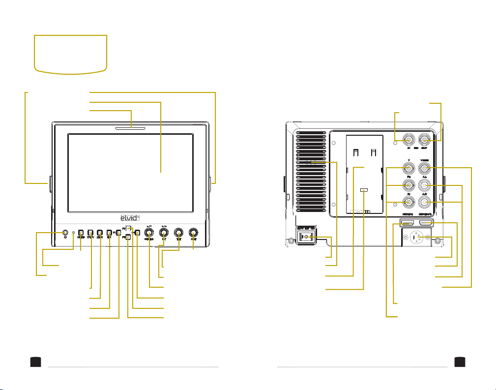
1/4″-20 threaded socket
Function F1 (Peaking) Function F3 (Level Meter)
Screen
Tally Light
FIELDVISION OCM-7PWV
Video button
Power LED
Headphone Jack SAT knob (R2)
YPbPr button BR/MENU knob (R1)
HDMI button Function F4 (Histogram)
SDI button Function F2 (Wave/Vector)
CONT knob (R4)
TINT knob (R3)
SDI Output
SDI Input
Power Switch 4-pin XLR DC
Speaker HDMI Output
Battery plate mount Audio inputs
Mini USB port
(factory use only)
Composite video
input
HDMI Input
YPbPr component
video inputs
76
Page 5
POWERING
ON & OFF
There are three ways to
power the FieldVision: the
4-pin XLR input, a standard
camera battery (see
Specications on page 24
for compatible battery
types), and a three-stud or
a V-mount battery.
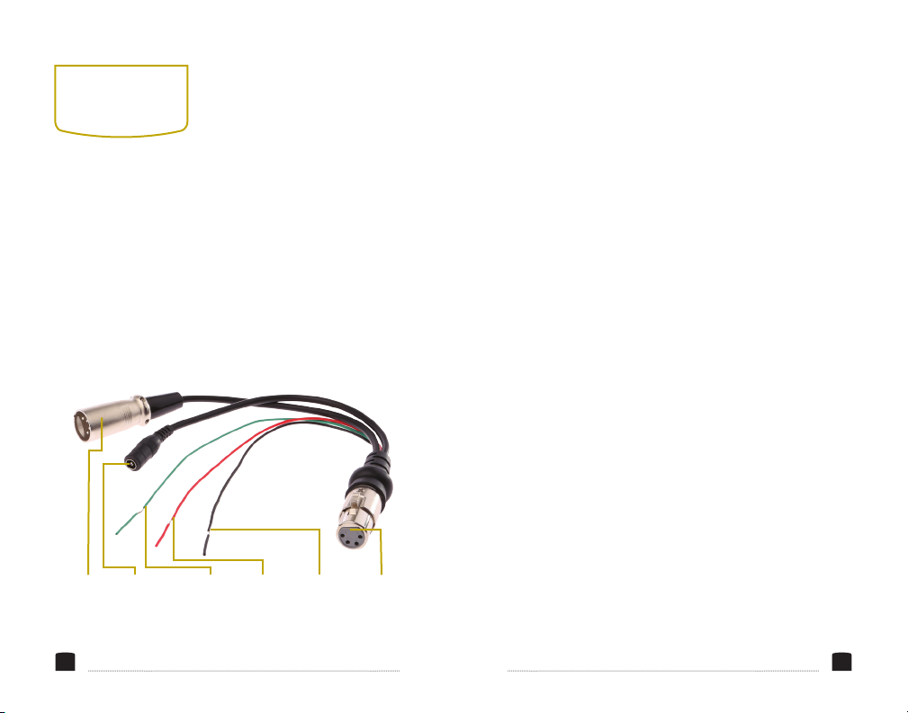
4-Pin XLR
8
Male
2.1mm DC
Input
Green
Tally
4
-PIN XLR
To power the FieldVision
via the 4-pin XLR
connector, use a compatible
cable to connect the
FieldVision’s 4-pin XLR DC
power input to your power
source.
Red Tally Tally
Ground
4-Pin XLR
Female
You can also use the included the 4-pin XLR power and
tally cable with either a 4-pin XLR cable connected to a
compatible power source, or with the included 12 V DC
adapter plugged into an AC power source.
To power the FieldVision via the 4-pin XLR power and tally
cable, follow these steps:
1. Fully insert the 4-pin XLR power and tally cable into the
4-pin XLR DC power input on the back of the monitor.
The connector should click into place when fully
inserted.
2. Use either a 4-pin XLR cable or the included 12 V DC
adapter to connect the corresponding connector on the
power and tally cable to your power source.
To turn on the FieldVision while using the
12 V DC adapter
or any other power source that uses the 4-pin XLR
connection, press the power switch to the “
12 V” position.
9
Page 6
POWERING
ON & OFF
CAMERA BATTERY
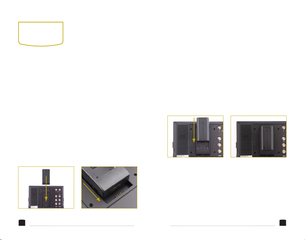
The FieldVision has a built-in mount for available battery
plates, which accommodate a variety of standard camera
batteries. This allows you to power the FieldVision with
easily-available batteries that you may already own. To
install a battery plate and a compatible battery, follow
these steps:
1. Place the battery plate
in the FieldVision’s battery
plate mount. Make sure the
plate’s bottom contacts are
aligned with the contacts
in the plate mount.
10 11
2. Slide the plate forward
until it locks into place.
3. Place a compatible
battery in the battery
plate. Make sure the
battery’s bottom contacts
are aligned with the
contacts in the battery plate.
To turn on the FieldVision while using one of the battery
plates, press the power switch to the “BATT” position.
For more information on compatible battery types, refer to
Specications on page 25.
4. Slide the battery forward
until it locks into place.
Page 7
POWERING
ON & OFF
THREE-STUD OR V-MOUNT
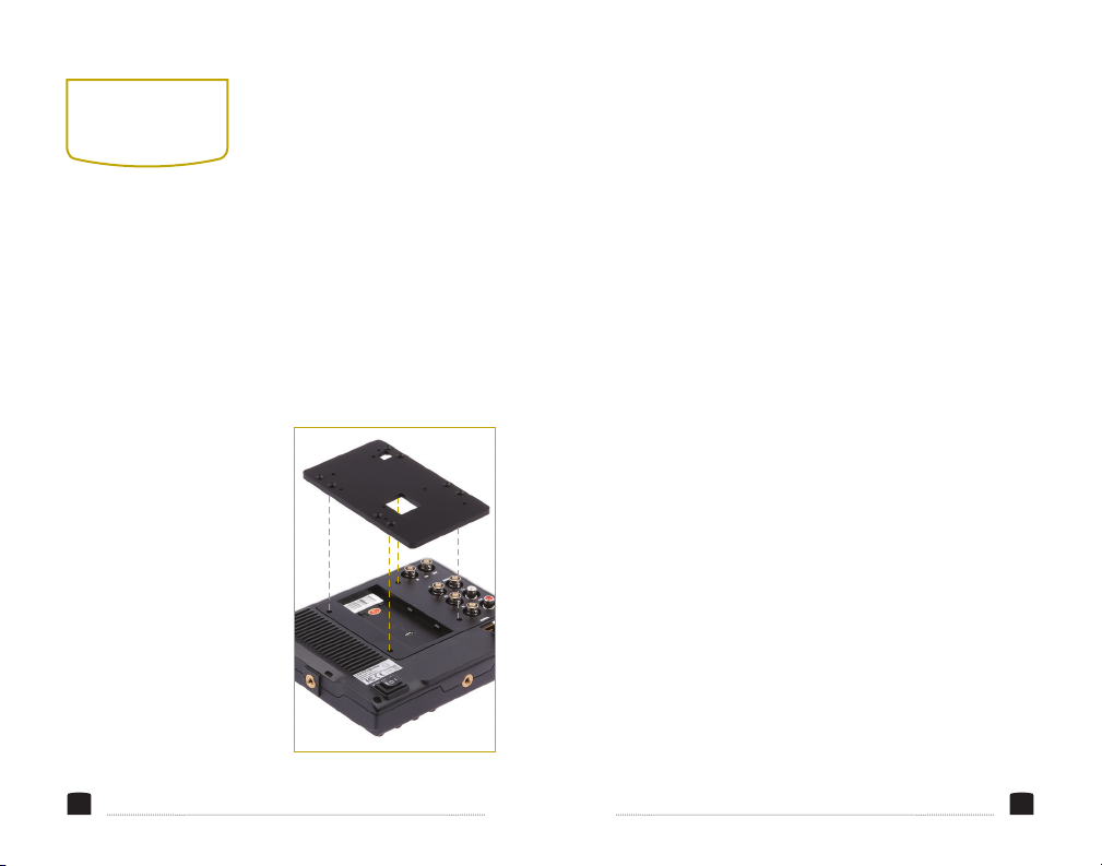
The FieldVision comes with an adapter panel that lets you
mount a Three-Stud or V-mount battery plate onto the back
of the monitor. These more powerful batteries provide longer
run-time than camera batteries, so you can work for longer
without having to recharge or change your battery. To install
the large battery adapter panel, follow these steps:
1. With the smooth side of
the adapter panel facing
up, place the panel on the
back of the monitor. Align
the top two screw holes
of the adapter panel with
the corresponding screw
holes in the back of the
monitor. The battery
power input should
be visible through the
bottom opening in the
adapter panel.
12 13
2. Insert the four included
screws into the adapter
panel and use a Phillipshead screwdriver to
screw them in until fully
tightened. Be careful not
to overtighten.
To turn on the FieldVision: If your battery plugs into the
battery power input, push the power switch in to the
“BATT” position. If your battery plugs into the 4-pin XLR
DC power input, push the power switch in to the “12V”
position.
3. Refer to your battery
plate’s instructions to
install your battery plate
and battery pack.
Page 8

USING THE
OCM-7PWV
MONITORING SOUND
You can monitor sound
via the integrated speaker
or the 3.5 mm stereo
headphone jack. To monitor
via the headphone jack,
plug in a pair of compatible
headphones.
MOUNTING THE FIELDVISION
Use one of the 1/4″-20
threaded sockets in the
FieldVision to attach the
monitor to your mounting
system. Make sure your
bracket can support the
monitor.
14
CONNECTING TO YOUR
CAMERA
To connect the FieldVision
to your camera, follow
these steps:
1. Choose the desired
video input, and use
the appropriate cable to
connect your camera to
the corresponding input
connections on the back
of the monitor.
2. Press the video input
button (Video, YPbPr,
HDMI, or SDI) that
corresponds to your
video input signal. The
button will glow to
indicate that the signal
is selected.
3. If you are using the tally light, connect the tally wires
to the corresponding wires in your studio tally system.
(See XLR diagram on pg. 8)
LOOP THROUGH
The FieldVision has SDI and HDMI loop-through. To loop
the video signal through the monitor, make sure your
camera is connected to either the SDI or HDMI video
input, and then connect the appropriate cable to the SDI or
HDMI output connection on the back of the monitor.
15
Page 9
THE
SUNSHADE
THE MENU
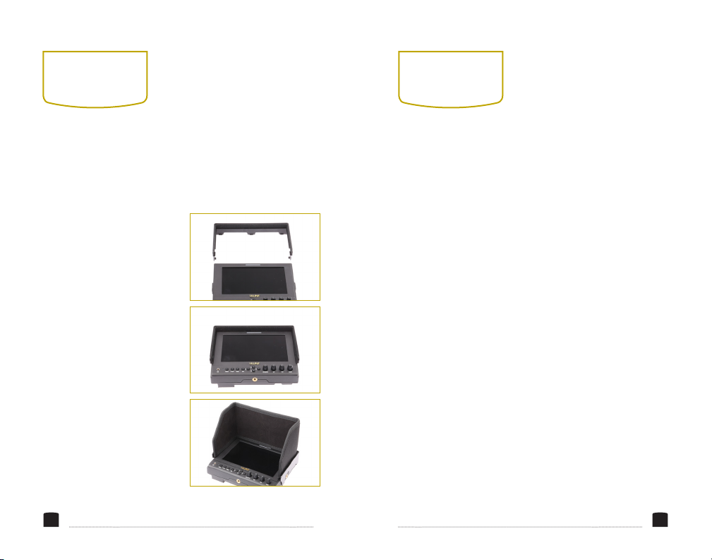
The sunshade prevents glare on the monitor’s screen by
blocking out stray light, and it's useful when shooting
outdoors. To attach the sunshade, follow these steps:
1. Mount the sunshade
bracket onto the
monitor by tting the
bracket’s clips into the
corresponding notches
along the top and sides of
the monitor.
2. Press down along the
bracket to make sure it’s
locked into place on both
the front and back of the
monitor.
3. Align the sunshade
cover’s touch fastener
with the one in the
bracket and attach it
securely.
16 17
Before using the FieldVision, you will need to make sure
the monitor’s settings are properly congured. All of the
setting congurations are located in the main menu, which
has four submenus: Video Settings, Onscreen Markers,
Tools and Scopes, and Custom Functions.
NAVIGATING THE MENU
To access the menu, press the BRI/MENU knob. The
four submenus are located in the top row of the main
menu window. Turn the SAT knob to scroll left or right to
highlight one of the submenus. To select a submenu and
scroll up or down through it, turn the BRI/MENU knob.
While scrolling through any vertical menu, turn the SAT
knob to select or adjust a menu item or value. Press the
BRI/MENU knob at any point to return to the previous
menu or screen.
Page 10

VIDEO
SETTINGS
COLOR TEMPERATURE
You can select from the
presets 6500, 7500,
and 9300 K. You can
also congure your
own custom setting,
which is labeled User in
the Color Temperature
menu. Customizing the
color temperature is
recommended only for
advanced users.
CHECK FIELD
In Check Field mode, just
the selected color will
appear onscreen. You can
select mono, red, green, or
blue. In mono, a grayscale
18 19
image will appear onscreen.
Check Field mode is useful
for calibrating the monitor.
ASPECT RATIO
You can set the aspect ratio
for the onscreen image.
The three options are full
screen (16:10), 4:3, and 16:9.
Full screen will stretch the
image to t the full size of
the FieldVision’s screen, and
4:3 and 16:9 will scale the
image to t those specic
aspect ratios. The default
setting is full screen.
PIXEL-TO-PIXEL
Use Pixel-to-Pixel mode to
turn off scaling and display
the incoming video signal
in its native resolution and
aspect ratio with 1:1 pixel
mapping. If the picture is
larger than the monitor’s
1280 × 800 resolution, the
center of the image will
appear onscreen.
CAMERA
Camera mode scales the
incoming video signal to ll
the screen. You can set it to
480p or 1080i.
H/V DELAY
This mode is recommended
only for broadcast
professionals. You can set
it to H&V Delay, V Delay,
and H Delay to display
the horizontal, vertical, or
combined view of the video
blanking signal.
UNDERSCAN
Underscan shrinks the
picture so you can see
the entire video image,
including the area that is
not broadcast-safe. You can
turn this mode on or off. The
default setting is off, which
displays only the broadcast-
safe image.
Page 11

ONSCREEN
MARKERS
CENTER MARKER
This setting displays a
marker in the center of the
screen.
SCREEN MARKERS
You can set the FieldVision
to display an onscreen box
as a safety frame marker
at a set percentage of the
screen size. You can set this
to 95%, 93%, 90%, 88%, 85%,
or 80%.
LANGUAGE
You can set the onscreen
language to English or
Chinese (中文).
PIP
Use PIP, or picture-in-picture
mode, to simultaneously
display two incoming video
signals. You can set the size
of the inset picture to small,
20 21
medium, and large; choose
PIP swap to switch the two
pictures; and move the inset
picture to different corners
of the screen.
SDI
Use this setting to turn the
connected 3G-SDI signal on
or off.
INPUT FORMAT OSD
Use this setting to set the
length of time the onscreen
menu is displayed. You can
choose 5, 10, or 15 seconds.
LOGO
Choose whether the Elvid
Fieldvision logo is displayed
when the monitor boots up.
FREEZE INPUT
Turning this setting on will
freeze the current onscreen
image.
IMAGE FLIP
This setting ips the display
horizontally, vertically, or
both.
WAVE/VECTOR
Waveform displays a
graph showing localized
exposure levels in the image.
Wherever a particular color
appears onscreen, it will
appear in the corresponding
area of the waveform graph.
Waveform can be set to
show the Y, R, G, B, Cb, or
Cr signals. Vector displays
a vectorscope, which is
an overall color saturation
meter for all colors in the
image.
WAVEFORM TRANS
Choose whether to make the
background of the onscreen
graphs translucent.
WAVEFORM SIZE
Choose the size of the
onscreen graphs: small or
large.
LEVEL METER
Display the audio level
meter onscreen.
MANUFACTURER DEFAULT
Restore the FieldVision to
the factory default settings.
Turn the SAT knob to
highlight OK or Cancel, and
then press the BRI/MENU
knob to make a selection.
ISP
For factory use only—do
not select this. If you select
this, immediately reboot the
FieldVision.
Page 12

CUSTOM
FUNCTIONS
For greater creative control over your images, you can assign
unique settings to the four function buttons and customize
the four knobs to suit your specic needs.
The options for customizing the function buttons are Center
Marker, Screen Marker, Check Field, Color Bar, Aspect
Ratio, Camera, PIP, Image Flip, Zoom, Pixel-to-Pixel, Freeze
Input, Underscan, H/V delay, Peaking, False Color, Exposure,
Histogram, Level Meter, and Wave/Vector. Functions not
already explained above are as follows:
COLOR BAR
Display color bars onscreen.
ZOOM
Zoom into the onscreen
image. When the video is
1080i, the available levels
of zoom are 2x and 8x. All
other resolutions can zoom
at 2x, 4x, and 8x.
22 23
PEAKING
Peaking is a focus-assist
tool that displays an
outline around in-focus
areas of the image. You
can choose mono or
color. Mono will display a
grayscale image with a red
fringe around the areas
that are in focus, and color
will display the full-color
image with the same red
fringe.
FALSE COLOR
This mode replaces the
color of the image with
set colors (see chart) so
you can determine how
your image is exposed.
The higher—or hotter—the
exposure, the closer the
colors will be to the top
of the chart. As exposure
decreases, the color will
descend through the chart.
EXPOSURE
Exposure mode displays
an animated black and
white outline, or zebra
exposure indicator, around
areas of the image that are
overexposed.
HISTOGRAM
The histogram indicates
the level of exposure from
light to dark and shows
what percentage of the
image is at what exposure
level. It can be set to Y to
show the overall exposure
level; Color to show an RGB
parade of red, green, and
blue levels on individual
scopes; and RGB to show
all four levels on the same
scope.
CUSTOMIZING THE KNOBS
You can assign the knobs,
labeled R1 through R4
in the Custom Functions
menu, to the following
settings: Contrast,
Brightness, Saturation,
Tint, Volume, Sharpness,
and BackLight.
All customizations are
available in the Custom
Functions menu. The
four knob customization
settings are on the same
list as the four function
button settings.
Page 13
SPECIFICATIONS
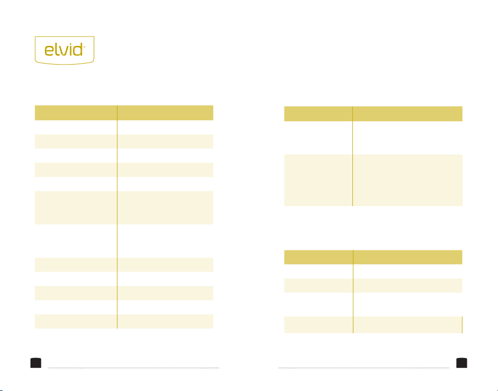
MONITOR
Display 7" LED backlit IPS panel
Native Resolution 1280×800
Brightness 400 cd/m²
Contrast 800:1
Viewing Angle (H/V) 178°/178°
Inputs 3G-SDI, HDMI,
component, composite,
analog audio
Outputs 3G-SDI, HDMI,
headphone (3.5 mm
stereo)
Input Voltage 12 V DC via 4-pin XLR
Current 900 mA
Power consumption ≤11 W
Signal Input AV1. AV2.HDMI
Power Consumption 8.0W
24
SIZE
Dimensions 7.5″ × 6.0″ × 1.2″ (5.6″ with
sunshade); 19.2 × 15.2 × 3.1
cm (14.1 cm with sunshade)
Weight Monitor: 1.7 lb. (0.76 kg)
With sunshade: 2.1 lb. (0.94 kg)
With carrying case: 4.8 lb.
(2.2 kg)
BATTERY PLATES
F-970 Sony L-series batteries
LPE6 Canon LP-E6 batteries
DU-21 Panasonic VBG-6 and similar
batteries
QM91D Sony M-series batteries
25
Page 14
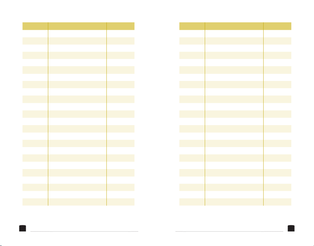
SINGAL MODE SUPPORT
Composite NTSC
PAL YES
YPBPR 480i (59.94)60 YES
576i (50) YES
480p (59.94)60 YES
576p (50) YES
720p (50) YES
720p (59.94) NO SIGNAL
720p (60)
1080i (50)
1080i (59.94)
1080i (60)
1080p (23.98)
1080p (24)
1080p (25) NO
1080p (29.97) NO SIGNAL
1080p (30)
1080p (50)
1080p (60)
1080p (23.98sF)
1080p (24sF) NO
HDMI 480i (59.94) YES
480i (60)
576i (50) YES
YES
YES
YES
NO SIGNAL
YES
NO SIGNAL
NO
NO
YES
YES
NO SIGNAL
YES
SINGAL MODE SUPPORT
HDMI 480p (59.94)
480i (60) YES
576i (50) YES
480p (59.94) YES
480p (60) YES
576p (50) YES
480p (59.94) YES
480p (60) YES
576p (50)
720p (23.98)
720p (24)
720p (25)
720p (29.97)
720p (30)
720p (50) YES
720p (59.94) YES
720p (60)
1080i (50)
1080i (59.94)
1080i (60)
1035i (59.94) YES
1035i (60) YES
1080p (23.976)
1080p (23.98) NO
YES
YES
NO
NO
NO
NO
NO
YES
YES
YES
YES
NO
26 27
Page 15
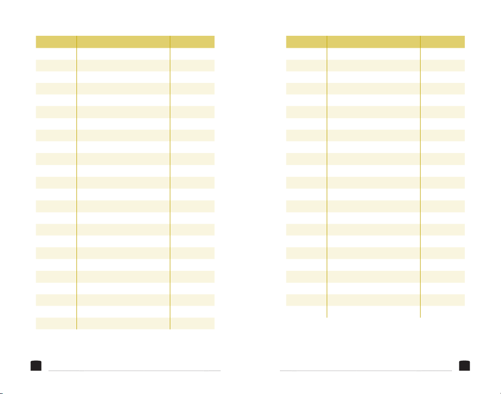
SINGAL MODE SUPPORT
HDMI 1080p (24)
1080p (25) NO
1080p (29.97) NO
1080p (30) NO
1080p (50) YES
1080p (59.94) YES
1080p (60) YES
1080p (23.98sF) NO SIGNAL
1080p (24sF)
2040 x 1080 (23.98sF)
2040 x 1080 (24sF)
2040 x 1080 (23.98p)
2040 x (24p)
SDI 480i (59.94)
480i (60) YES
576i (50) YES
480p (59.94)
480p (60)
576p (50)
720p (23.98)
720p (24) NO
720p (25) NO
720p (29.97)
720p (30) NO
NO
NO
NO SIGNAL
NO SIGNAL
NO SIGNAL
NO SIGNAL
YES
NO
NO
NO
NO SIGNAL
NO SIGNAL
SINGAL MODE SUPPORT
SDI 720p (50)
720p (59.94) YES
720p (60) YES
1080i (50) YES
1080i (59.94) YES
1080i (60) YES
1035i (59.94) NO SIGNAL
1035i (60) NO SIGNAL
1080p (23.976)
1080p (23.98)
1080p (24)
1080p (25)
1080p (29.97)
1080p (30)
1080p (50) YES
1080p (59.94) YES
1080p (60)
1080p (23.98sF)
1080p (24sF)
2040 x 1080 (23.98PsF)
2040 x 1080 (24PsF) NO SIGNAL
2040 x 1080 (23.98p) NO SIGNAL
2040 x 1080 (24p)
YES
NO
NO SIGNAL
NO
NO
NO
NO
YES
NO SIGNAL
NO
NO
NO SIGNAL
28 29
Page 16
TROUBLE
SHOOTING
PROBLEM SOLUTION
The FieldVision will not
turn on.
The screen displays only
a black and white image.
• If you are powering the
FieldVision with a battery, make
sure that the battery is fully
charged and that the battery
plate is properly connected.
• If you are powering the
FieldVision via AC power, make
sure that the power and tally
cable and the 12 V DC adapter
are fully plugged in, and that
your AC power source is reliable.
Try switching AC power sources.
• Make sure the FieldVision’s
power switch is set to the proper
power input.
• Check whether the color
saturation is properly congured.
• Make sure the Check Field and
Peaking modes are disabled.
PROBLEM SOLUTION
(cont'd) • If you are using component video,
The FieldVision is
turned on but there is
no onscreen image.
“No signal” or
“not supported” is
displayed onscreen.
The colors are
inaccurate.
make sure that all the cables are
attached and fully plugged into the
proper inputs.
• Make sure that the correct input
signal is selected.
• Check your cables to make sure
they are properly connected.
• Check your cables to make sure
they are reliable.
Make sure the video resolution
and frame rate are supported by
the monitor. See the Supported
Resolutions and Frame Rates chart
on page 26-29.
• Check your cables to make sure
they are properly connected.
• Make sure False Color mode is
disabled.
• Make sure your monitor is
properly calibrated.
•Check your cables to make sure
they are reliable.
30 31
Page 17

ONE-YEAR LIMITED WARRANTY
This Elvid product is warranted to the original purchaser to be free from
defects in materials and workmanship under normal consumer use for
a period of one (1) year from the original purchase date or thirty (30)
days after replacement, whichever occurs later. The warranty provider’s
responsibility with respect to this limited warranty shall be limited solely
to repair or replacement, at the provider’s discretion, of any product
that fails during normal use of this product in its intended manner
and in its intended environment. Inoperability of the product or part(s)
shall be determined by the warranty provider. If the product has been
discontinued, the warranty provider reserves the right to replace it with
a model of equivalent quality and function.
This warranty does not cover damage or defect caused by misuse,
neglect, accident, alteration, abuse, improper installation or maintenance.
EXCEPT AS PROVIDED HEREIN, THE WARRANTY PROVIDER
MAKES NEITHER ANY EXPRESS WARRANTIES NOR ANY IMPLIED
WARRANTIES, INCLUDING BUT NOT LIMITED TO ANY IMPLIED
WARRANTY OF MERCHANTABILITY OR FITNESS FOR A PARTICULAR
PURPOSE. This warranty provides you with specic legal rights, and you
may also have additional rights that vary from state to state.
To obtain warranty coverage, contact the Elvid Customer Service
Department to obtain a return merchandise authorization (“RMA”)
number, and return the defective product to Elvid along with the RMA
number and proof of purchase. Shipment of the defective product is at
the purchaser’s own risk and expense.
For more information or to arrange service, visit www.elvidcinema.com
or call Customer Service at 212-594-2353.
Product warranty is provided by the Gradus Group. www.gradusgroup.com
Elvid is a registered trademark of the Gradus Group.
© 2014 Gradus Group LLC.All Rights Reserved.
www.elvidcinema.com
TM
ELVID
A Gradus Group Brand
 Loading...