

Page 1

IP address:192.168.1.10
Username:admin
Password:password
Wireless access point
WEP-2ac, WEP-2ac Smart
User manual
Firmware version1.15.0
Page 2

WEP-2ac, WEP-2ac Smart user manual
2
Contents
1 Introduction ................................................................................................................................................3
1.1 Symbols.................................................................................................................................................. 3
2 Device Description .....................................................................................................................................4
2.1 Purpose .................................................................................................................................................. 4
2.2 Devices specifications........................................................................................................................... 4
2.3 Technical parameters of the devices ................................................................................................... 6
2.4 Design..................................................................................................................................................... 7
2.4.1 Main panel of the devices ..................................................................................................................7
2.5 Light indication....................................................................................................................................... 8
2.6 Factory reset .......................................................................................................................................... 8
2.7 Delivery package.................................................................................................................................... 8
3 Installation rules.........................................................................................................................................9
3.1 Safety rules............................................................................................................................................. 9
3.2 Installation recommendations .............................................................................................................. 9
3.3 Calculating the required number of access points.............................................................................. 9
3.4 Channel selection for neighboring access points.............................................................................. 10
3.5 WEP-2ac, WEP-2ac Smart installation................................................................................................ 11
3.5.1 Wall mounting ...................................................................................................................................12
3.5.2 Mounting to a false ceiling...............................................................................................................13
3.5.3 Removing the device from the bracket............................................................................................13
4 Application A. Anntenna patterns of WEP-2ас and WEP-2ac Smart ....................................................14
5 Application B. Connectors pin array .......................................................................................................15
6 The list of changes ..................................................................................................................................16
Page 3

WEP-2ac, WEP-2ac Smart user manual
3
1 Introduction
Modern tendencies of telecommunication development necessitate operators to search for the most optimal
technologies, allowing you to satisfy drastically growing needs of subscribers, maintaining at the same time
consistency of business processes, development flexibility and reduction of costs of various services provision.
Wireless technologies are spinning up more and more and have paced a huge way for a short time from unstable
low-speed communication networks of low radius to broadband networks equitable to speed of wired networks
with high criteria for the quality of provided services.
WEP-2ac and WEP-2ac Smart are Wi-Fi access points of the Enterprise class. The devices are dedicated to be
installed inside buildings as access points and to create a seamless wireless network using several identical
access points on a large area.
This manual specifies intended purpose, main technical parameters, design, installation procedure, safe operation
rules and installation recommendations for WEP-2ac and WEP-2ac Smart wireless access points.
1.1 Symbols
Notes and warnings
Notes contain important information, tips or recommendations on the device operation and setup.
Warnings are used to inform the user about harmful situations for the device and the user alike, which
could cause malfunction or data loss.
Page 4

WEP-2ac, WEP-2ac Smart user manual
4
2 Device Description
2.1 Purpose
WEP-2ac and WEP-2ac Smart wireless access points (hereinafter the devices) are designed to provide users with
access to a high-speed and safe network.
The devices are dedicated to create L2 wireless networks interfacing with a wired network. WEP-2ac and WEP-2ac
Smart are connected to a wired network via 10/100/1000M Ethernet interface and arrange high-speed access to
the Internet for devices supporting Wi-Fi technology at 2.4 and 5 GHz. The devices have two radio interfaces to
organize two physical wireless networks.
WEP-2ac and WEP-2ac Smart support high requirement to the quality and allows transmitting more important
traffic in more priority queue. Prioritization is provided due to QoS main technologies: CoS (tags in VLAN packet
fields) and ToS (tags in IP packets). Besides the standard methods of prioritization, the devices allow you to
assign demands for traffic transmission almost in every packet field from MAC to TCP/UDP port. The ACL rules
and shaping allow you to control access, quality of service and restrictions for all subscribers as well as for each
subscriber individually.
The devices are designed to be installed in offices, state buildings, conference halls, laboratories, hotels, etc. The
creation of virtual access points with different types of encryption allows clients to delimit access rights among
users and groups of users.
2.2 Devices specifications
Interfaces:
• 1 Ethernet 10/100/1000Base-T (RJ-45) port with PoE+ support;
• Console RJ-45 .
Functions:
WLAN capabilities:
• Support for IEEE 802.11a/b/g/n/ac standards;
• Data aggregation including A-MPDU (Tx/Rx) and A-MSDU (Rx);
• WMM-based packet prioritization and scheduling;
• Dynamic frequency selection (DFS);
• Support for Hidden SSID;
• 32 virtual access points;
• Third-party access point detection;
• Workgroup bridge;
• WDS;
• APSD.
Network functions:
• Auto-negotiation of speed, duplex mode and switching between MDI and MDI-X modes;
• Support for VLAN;
• Authentication support 802.1X;
• Support for 802.11r;
• DHCP Client;
• IPv6;
• LLDP;
• ACL;
• SNMP;
• GRE.
Page 5
WEP-2ac, WEP-2ac Smart user manual
5
Cluster operation mode:
• Organization of a cluster with capacity of up to 64 access points;
• Automatic synchronization of the access points configurations in a cluster;
• Automatic firmware update for access points in a cluster;
• Single Management IP — united address to control access points in a cluster;
• Auto-distribution of frequency channels among access points;
• Auto-distribution of output poweramong access points.
QoS functions:
• Priority and profile-based packet scheduling;
• Bandwidth limitation for each SSID;
• Changing WMM parameters for each radio interface.
Security
• E-mail notification on system events;
• Centralized authorization via RADIUS server (WPA Enterprise);
• WPA/WPA2;
• Captive Portal;
• Support for Internet Protocol Security (IPsec)
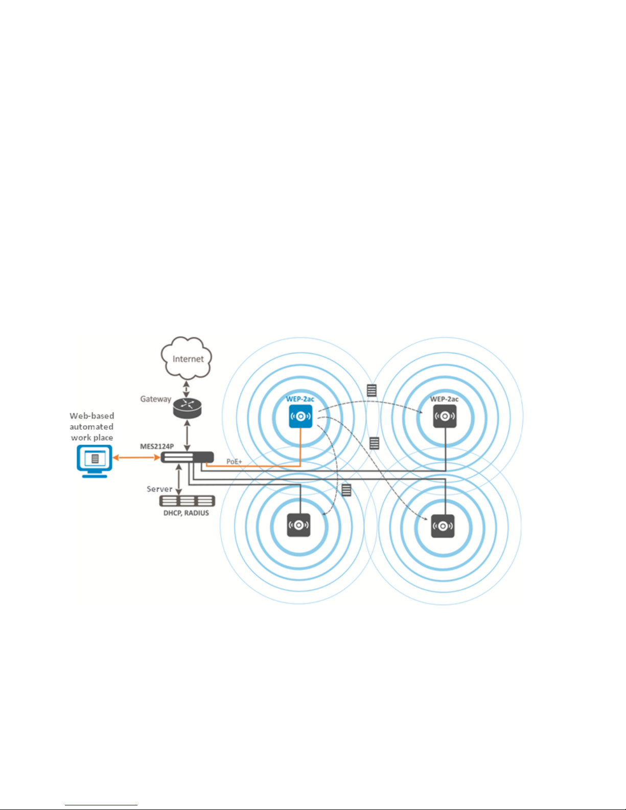
The figure below illustrates an application scheme of WEP-2ac.
Page 6

WEP-2ac, WEP-2ac Smart user manual
6
2.3 Technical parameters of the devices
WANEthernet interface parameters
Number of ports 1
Connector RJ-45
Data rate, Mbps 10/100/1000, auto-negotiation
Standards BASE-T
Parameters of the wireless interface
Standards 802.11a/b/g/n/ac
Frequency range, MHz 2400–2483.5 MHz, 5150–5850 MHz
Modulation CCK, BPSK, QPSK, 16QAM, 64QAM, 256QAM
Operating channels 802.11b/g/n: 1–13 (2412–2472 MHz)
802.11a/ac: 36–64 (5180–5320 MHz), 100–144 (5500–5720 MHz),
149–165 (5745–5825 MHz)
Data rate, Mbps 6, 9, 12, 18, 24, 36, 48, 54, MCS0-MCS15, MCS0-9 NSS1, MCS0-9
NSS2
802.11n: up to 144.4 Mbps (channel 20 MHz), up to 300 Mbps
(channel 40 MHz)
802.11ac: up to 866.7 Mbps (80 MHz)
Maximum output power of the transmitter
(Defined by Transmit Power Limit and Transmit
Power Control)
2.4 GHz: up to 18 dBm
5 GHz: up to 21 dBm
Receiver sensitivity 2.4 GHz: up to -98 dBm; 5 GHz: up to -94 dBm
Security Centralized authentication via RADIUS server (WPA Enterprise)
64/128/152-bit WEP encryption, WPA/WPA2
Support for Captive Portal
E-mail notification on system events
Support for 2х2 MIMO
Two embedded Broadcom chips: BCM47452 (5 GHz, IEEE 802.11a/n/ac) and BCM43217 (2.4 GHz, IEEE 802.11b/g/n)
Management
Remote management Web interface, Telnet, SNMP, SSH, EMS management system.
Firmware update and configuration through DHCP Autoprovisioning
Access restriction by password, by IP address
Page 7

WEP-2ac, WEP-2ac Smart user manual
7
General parameters
Processor Broadcom BCM47452
NAND 128 MB NAND Flash
RAM 256 MB RAM DDR3
Power supply PoE+ - 48V/54V (IEEE 802.3at-2009).
Power consumption no more than 13 W
Operating temperature from +5 to +40°С
Operating humidity at 25°С up to 80%
Dimensions of WEP-2ac 200х40 mm
Dimensions of WEP-2ac Smart 200х43 mm
Weight no more than 0.4 kg
2.4 Design
WEP-2ac, WEP-2ac Smart are housed in a plastic case.
2.4.1 Main panel of the devices
The figure below shows a layout of WEP-2ac and WEP-2ac Smart main panel:
The following light indicators, connectors and controls are located on the main panel of WEP-2ac, WEP-2ac Smart:
Main panel element Description
1 Link/Speed Light indication of GE port (PoE)
2 GE (PoE) GE port for power supply through PoE+
3 Console Console port RS-232 for local management
4 F Functional key
5 Wi-Fi Indicators of Wi-Fi modules activity
Page 8

WEP-2ac, WEP-2ac Smart user manual
8
2.5 Light indication
The Wi-Fi, LAN and power indicators show the device current state. The table below lists possible status of the
LEDs.
LED LED state Device state
Wi-Fi (5) green LED glows constantly Wi-Fi is enabled
green flashes The process of data transmission trough a wireless
network
LAN (1) green LED (10, 100 Mbps)/ orange LED
(1000 Mbps)
the link with the connected network device is established
green LED flashes the process of packet data transmission through LAN
interface
Power
(located on
the front
panel)
green LED glows constantly the device power supply is enabled, normal operation, IP
address is obtained
orange LED glows constantly the device is loaded but IP address is not received via DHCP
red LED glows constantly the device is loading
2.6 Factory reset
In order to reset the device to factory settings, press and hold the 'F' button until «Power» indicator flashes. The
device is rebooted automatically. DHCP client is launched by default.
If the address is not received via DHCP, the device will have IP address – 192.168.1.10 and subnet mask –
255.255.255.0.User Name and Password to access via Web interface: admin/password.
2.7 Delivery package
The delivery package includes:
• Wireless access point WEP-2ac/WEP-2ac Smart;
• Mounting kit;
• User manual (supplied on a CD);
• Conformity certificate;
• Technical passport.
Page 9

WEP-2ac, WEP-2ac Smart user manual
9
3 Installation rules
This section defines safety rules, installation recommendations, setup procedure and the device starting
procedure.
3.1 Safety rules
1. Do not install the device near heat sources and in rooms with environment temperature below 5°С or higher
40°С.
2. Do not use the device in room with high level of humidity. Do not expose the device to smoke, dust, water,
mechanical vibrations or shocks.
3. Do not open the case of the device. There are no user serviceable parts inside.
3.2 Installation recommendations
1. Recommended location for device installation: horizontal, on a ceiling.
2. Before you install and enable the device, check the device for visible mechanical defects. If defects are
observed you should stop the device installation, draw up corresponding act and contact the supplier.
3. If the device has been exposed for a long time at a low temperature, it must be left to stand for two hours at
room temperature before use. After a long stay of the device in conditions of high humidity, let it stand
under normal conditions for at least 12 hours before switching on.
4. During the device installation to provide Wi-Fi coverage area with the best characteristics take into account
the following rules:
a. Install the device at the center of the wireless network;
b. Minimize the number of obstacles (walls, roof, furniture, etc.) between WEP-2ac/WEP-2ac Smart and
other wireless network devices;
c. Do not install the device near (about 2 m) electrical and radio devices;
d. It is not recommended to use radiophone and other equipment operating at the frequency of 2.4 GHz,
5 GHz in Wi-Fi effective radius;
e. Obstacles in the form of glass/metal constructions, brick/concrete walls, water cans and mirrors can
significantly reduce Wi-Fi action radius. It is not recommended to place the device inside a false
ceiling as metal frame causes multipath signal propagation and signal attenuation.
5. In case of the installation of several access points, cell action radius must overlap with action radius of a
neighboring cell at level of -65 ÷ -70 dBm. Increasing this level up to -75 dBm is allowed if it does not involve
the use of VoIP, streaming video and other traffic that is sensitive to losses in a wireless network.
3.3 Calculating the required number of access points
To calculate the required number of access points, you need to evaluate the required coverage zone. For a more
accurate assessment, it is necessary to make a radio examination of the room. Approximate radius of coverage
area of WEP-2ac with a good-quality signal in case of mounting on a ceiling in typical office: 40-50 m at 2.4 GHz
and 20-30 m at 5 GHz. In case of no obstacles, the radius of the coverage area is up to 100 m at 2.4 GHz and up to
60 m at 5 GHz.
The table below describes rough attenuation values.
Do not cover ventilation holes and do not put other objects on the device in order to prevent
overheating of device components.
Page 10

WEP-2ac, WEP-2ac Smart user manual
10
Material Change of signal level, dB
2.4 GHz 5 GHz
Organic glass -0.3 -0.9
Brick -4.5 -14.6
Glass -0.5 -1.7
Plaster slab -0.5 -0.8
Wood laminated plastic -1.6 -1.9
Plywood -1.9 -1.8
Plaster with wirecloth -14.8 -13.2
Breezeblock -7 -11
Metal lattice (mesh 13*6mm, metal 2mm) -21 -13
3.4 Channel selection for neighboring access points
• It is recommended to set non-overlapping channels to avoid interchannel interference between neighboring
access points.
General diagram of frequency channel closure in the range of 2.4 GHz
• The example of channel allocation scheme among neighboring access points in the frequency range of 2.4
GHz when channel width is 20 МHz:
Page 11

WEP-2ac, WEP-2ac Smart user manual
11
Scheme of channel allocation among neighboring access points in the frequency range of 2.4 GHz when channel
width is 20 MHz
• It is recommended to save the same allocation scheme between floors, see the figure below:
Scheme of channel allocation between neighboring access points that are located on different floors
• When the width of used channel is 40 MHz, there is no non-overlapping channels in the frequency range of
2.4 GHz. In such cases, you should select channels maximally separated from each other:
Channels used in a range of 5GHzwhen channel width is 20, 40 or 80 MHz
3.5 WEP-2ac, WEP-2ac Smart installation
The devices can be installed on plain surface (wall, ceiling) according to safety rules and recommendations
mentioned above.
The device delivery package includes required mounting kit to attach the device to plain surface.
Page 12

WEP-2ac, WEP-2ac Smart user manual
12
3.5.1 Wall mounting
1. Fix the bracket (included in the delivery package) to the wall:
Attaching the bracket to a wall
a. The figure shows the bracket allocation.
b. Pass the wires into the corresponding grooves on the bracket while installing the bracket.
c. Align together three bolt holes on bracket and bolt holes on the wall. Screw the brackets to the wall by
using a screwdriver.
2. Install the device
Device installation (front view)
a. Connect cables to the corresponding device connectors, the description of the device connectors is
represented in section Design.
b. Align the device and bracket together, fix the position, turning clockwise.
Page 13

WEP-2ac, WEP-2ac Smart user manual
13
3.5.2 Mounting to a false ceiling
1 – metal bracket;
2 – armstrong panel;
3 – plastic bracket;
4 – device.
1. Fix metal and plastic bracket to a ceiling.
2. Plastic bracket (3) should be join to a metal one (1) on a false ceiling in the following order: metal bracket ->
armstrong panel -> plastic bracket.
3. Cut the hole in the armstrong panel. The size of the hole should be equal to hole of metal bracket. Conduct
wires through the hole.
4. Align holes in metal bracket with holes of armstrong panel and plastic bracket. Screw the brackets by using
a screwdriver.
5. Install the device.
a. Connect cables to the corresponding device connectors, the description of the device connectors is
represented in section Design.
b. Align the device and bracket together, fix the position, turning the device clockwise.
3.5.3 Removing the device from the bracket
For removing the device from the bracket:
1. Turn the device counter-clockwise.
2. Remove the device.
It is not recommended to place the device inside a false ceiling as metal frame causes multipath signal
propagation and signal attenuation.
Page 14

WEP-2ac, WEP-2ac Smart user manual
14
4 Application A. Anntenna patterns of WEP-2ас and WEP-2ac Smart
2.4 GHz range
5 GHz range
Page 15

WEP-2ac, WEP-2ac Smart user manual
15
5 Application B. Connectors pin array
RJ-45 pin array
The following scheme is used in case of connection via twisted-pair wire.
Side А:
1. white-orange;
2. orange;
3. white-green;
4. blue;
5. white-blue;
6. green;
7. white-brown;
8. brown.
Console cable RJ45-DB9 pin array
Serial Port (RJ-45 Connector) Pin Adapter (DB-9) Pin
3 (TXD) 2 (RXD)
4 (Signaling Ground) 5 (Signaling Ground)
5 (Signaling Ground) 5 (Signaling Ground)
6 (RXD) 3 (TXD)
The example of implementation is shown on the following figure:
Page 16

WEP-2ac, WEP-2ac Smart user manual
16
6 The list of changes
Document's version Date of issue Changes
Version 1.8 30.11.2018
Synchronization with firmware version 1.15.0
Version 1.7 10.08.2018
Synchronization with firmware version 1.14.0
Version 1.6 8.05.2018
Synchronization with firmware version 1.12.2
Changes:
• Device description
Version 1.5 26.12.2017 Synchronization with firmware version 1.11.4
Version 1.4 30.10.2017 Synchronization with firmware version 1.11.2
Version 1.3 02.08.2017 Synchronization with firmware version 1.10.0
Version 1.2 01.02.2017 Synchronization with firmware version 1.9.0
Version 1.1 16.12.2016 Synchronization with firmware version 1.8.0
Version 1.0 20.07.2016 First edition
Firmware version 1.15.0
Page 17

WEP-2ac, WEP-2ac Smart user manual
17
TECHNICAL SUPPORT
Contact Eltex Service Center to receive technical support regarding our products:
29v Okruzhnaya Street, Novosibirsk, Russian Federation, 630020.
Technical support phone numbers:
+7(383) 274-47-87,
+7(383) 272-83-31,
E-mail: techsupp@eltex.nsk.ru
Visit Eltex official website to get the relevant technical documentation and software, benefit from our knowledge
base, send us online request or consult a Service Centre Specialist in our technical forum.
Eltex official website: http://eltex-co.ru
Technical forum: http://eltex-co.ru/forum
Knowledge base: *http://eltex-co.ru/support/knowledge*
Download center: *http://eltex-co.ru/support/downloads*
 Loading...