

Page 1

Username:admin
Password:password
IP phones
VP-12, VP-12P
Operation manual
Firmware version1.5.0
Page 2

VP-12, VP-12P IP phones. Operation manual
2
Table of content
1 Device description .............................................................................................................4
1.1 Intended use............................................................................................................................... 4
1.2 Device design and Operating principle ..................................................................................... 5
1.3 Main specifications ................................................................................................................... 6
1.4 Design....................................................................................................................................... 10
1.5 Status indication on graphic display....................................................................................... 12
1.6 Delivery package...................................................................................................................... 13
2 Managing VP-12(P) via web interface ............................................................................14
2.1 Getting started ......................................................................................................................... 14
2.2 Configuring VP-12(P)............................................................................................................... 18
2.3 Monitoring VP-12(P) ................................................................................................................ 74
3 Example of device configuration ....................................................................................84
4 Appendices to VP-12(P) operation manual....................................................................89
4.1 Device automatic update algorithm based on DHCP ............................................................ 89
4.2 System recovery after firmware update failure...................................................................... 92
4.3 Running user-defined script upon system startup................................................................. 92
4.4 DHCP client configuration in multiservice mode................................................................... 94
Page 3

VP-12, VP-12P IP phones. Operation manual
3
IP phones VP-12 and VP-12P(hereinafter the "device") are designed to provide VoIP services to the network
clients. The device is intended for operation in home or small office (SMB) environment.
This operation manual describes intended use, key specifications, configuration, monitoring, and firmware
update for VP-12(P) IP phones.
Page 4
VP-12, VP-12P IP phones. Operation manual
4
1 Device description
• Intended use
• Device design and Operating principle
• Main specifications
• Design
• Top panel of the device. Light indication
• Rear panel of the device
• Status indication on graphic display
• Delivery package
1.1 Intended use
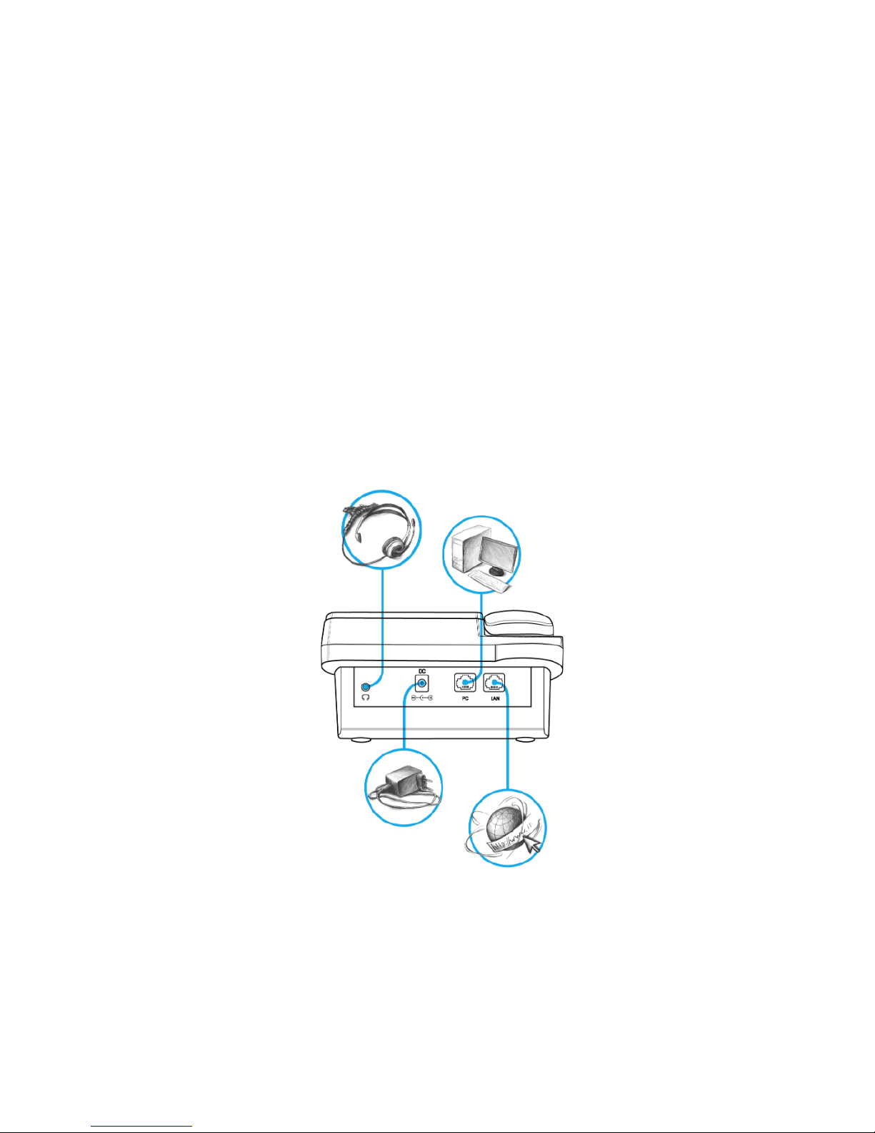
VP-12P – IP phone providing voice services and PC connection to IP network via only one cable. The device
supports PoE technology and has advanced functionality, high quality, and universal style.
VP-12P is designed for organizations with high requirements to transmitted voice data, stability and usability.
The figure below shows VP-12(P) connection diagram:
VP-12(P) connection diagram
Page 5
VP-12, VP-12P IP phones. Operation manual
5
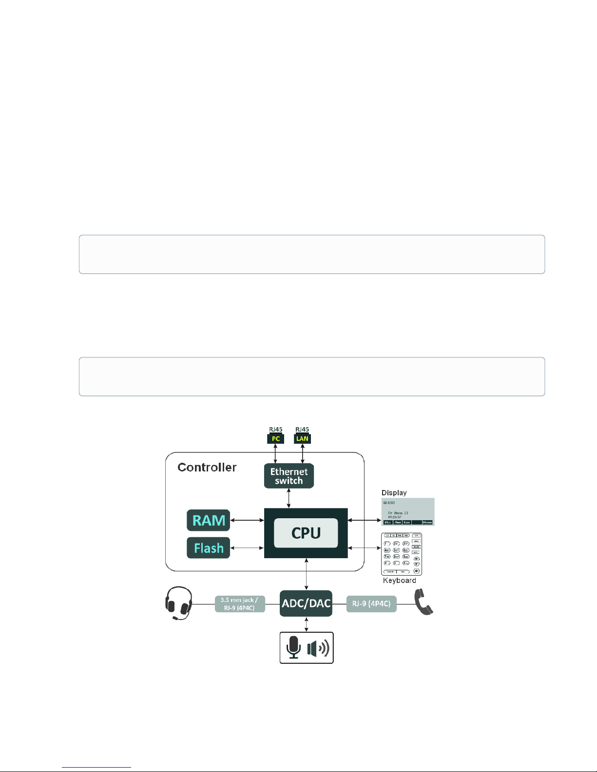
1.2 Device design and Operating principle
VP-12(P) IP phone includes the following subsystem:
• Controller featuring:
• Realtek RTL8972C highly-integrated System-on-a-Chip (SoC), including a CPU, 100 Mbits switch
with a built-in PHY, hardware L2/L3/L4 acceleration;
• flash-memory–16MВ;
• SDRAM –128MВ;
• codec(ADC/DAC);
• 3.2 inch liquid crystal display with 128x64 px resolution;
• Realtek ALC5621 or Realtek ALC5633Q voice codec;
• Fully-featured digital keyboard with additional function keys;
• 1 x LAN port: RJ-45 10/100BASE-T;
• 1 x PC port: RJ-45 10/100BASE-T;
• 1 x Handset port: RJ-9 (4P4C) for connecting a handset;
• 1 x Headset: 3.5 mm jack or RJ-9 for connecting a headset;
Design diagram for device is depicted in the figure below.
Depending on hardware version: for versions below 2.0 — Realtek ALC5621 codec; for versions
2.0 and later — Realtek ALC5633Q codec.
Depending on hardware version: for versions below 2.0 — 3.5 mm jack; for versions 2.0 and later
— RJ-9 (4P4C).
Page 6

VP-12, VP-12P IP phones. Operation manual
6
The device runs under Linux operating system. Basic control functions are performed by Realtek processor
which enables IP packet routing, VoIP operation, etc.
1.3 Main specifications
General parameters
Power supply
• power adapter 5V DC, 2 А
• PoE support (IEEE 802.3af), class 2
Power consumption up to 3.5 W (max. current consumption is0.7 А)
Operating temperature range from +5 to +40°C
Relative humidity at 25°С no more than 80%
Dimensions 223x178x89,5 mm
Weight up to 0.52 kg
Interfaces
• LAN: 1 port of Ethernet RJ-45 10/100BASE-T
• PC: 1 port of Ethernet RJ-45 10/100BASE-T
• Handset: 1 RJ-45 (4P4C) port for connecting a handset
• Headset: 1 port for connecting a headset
Ethernet LAN interface specification
Number of ports 1
Electric port RJ-45
Data transmission rate
• 10 Mbps
• 100 Mbps
• autonegotiation
Standard support
BASE-T
Ethernet PC interface specification
Number of ports 1
Electric port RJ-45
Data transmission rate
• 10 Mbps
• 100 Mbps
• autonegotiation
Standard support
BASE-T
Page 7

VP-12, VP-12P IP phones. Operation manual
7
Main features and capabilities
VoIP capabilities
Supported protocols
• SIP
Quantity of accounts 2
Key features
• 2 SIP accounts configuring independently
• Support for up to 4 redundant SIP servers
• Flexible dialplan
• Operation without a SIP server
• Caller name and number displaying (CallerID)
• Mute
• Redial
• Different ring-tones for different accounts
• Call History
• Local phonebook for 200 phone numbers
• LDAP Remote Phonebook
• Speakerphone mode
• Operation behind NAT
• Short text messages transmitting and receiving (SIP MESSAGE)
Operation behind NAT
• NAT keepalive
• STUN mode
• Public IP
Security
• SIP over TLS
• SRTP
Voice features
• Echo cancellation, G.165, G.168 (AEC) recommendations
• Voice activity detector (VAD)
• Comfort Noise Generation (CNG)
• DTMF signals detection and generation
DTMF signals detection and
generation
• Inband
• RFC2833
• SIP INFO
Codecs
• G.711а
• G.711u
• G.723.1
• G.726
• G.729
Page 8

VP-12, VP-12P IP phones. Operation manual
8
Value Added services
• Call Hold
• Call Transfer
• Call Waiting;
• Call Forward on Busy
• Call Forward on No response
• Call Forward Unconditional
• Do not disturb (DND)
• Caller Line Identification Restriction – CLIR
• Hotline/Warmline
• 3 Way-conference
• Stop dialing by pressing #
Network features
Key features
• Opportunity to divide voip, managment and pc-data traffic to different
vlans
Protocols
• Static IP
• DHCP
• PPPOE
Support for PPPoE
• PAP, SPAP and CHAP authorization
• PPPoE compression
Support for DHCP option 1 - Subnet Mask
3 - Router
6 - Domain Name Server
12 - Host Name
15 - Domain Name
26 - Interface MTU
28 - Broadcast Address
33 - Static Route
42 - Network Time Protocol Servers
43 - Vendor-Specific Information
66 - TFTP ServerName
67 - Bootfile name
120 - SIP Servers
121 - Classless Static Route
249 - Private/Classless Static Route(Microsoft)
Support for QoS mechanisms
• IP DSCP header
• 802.1P
Support for DNS
• Static DNS servers addresses
• Obtaining DNS servers addresses via DHCP
Support for NTP
• Static NTP server address assignment
• Obtaining NTP server address via DHCP
Network access limitation
• Firewall
• MAC filter
Page 9

VP-12, VP-12P IP phones. Operation manual
9
Routing
• Static routing
• Routing rules assignment via DHCP (Option 33, 121, 249)
Mangement and monitoring
Key features
• Access limitation through network interfaces
• Flexible settings for access to display menu
• Bilingual
Interfaces
• Web interface
• SSH
• Telnet
• TR-069
• Display menu
Debug information output
• Syslog
• Telnet
• File
Loading/updating of software and
configuration
• Autoupdate by schedule
• Periodical autoupdate
• Centralized software update through ACS server (TR-069)
Page 10
VP-12, VP-12P IP phones. Operation manual
10
1.4 Design
VP-12(P) IP phone is enclosed into 223x178x89.5 mm plastic case.
1.4.1 Top panel of the device. Light indication
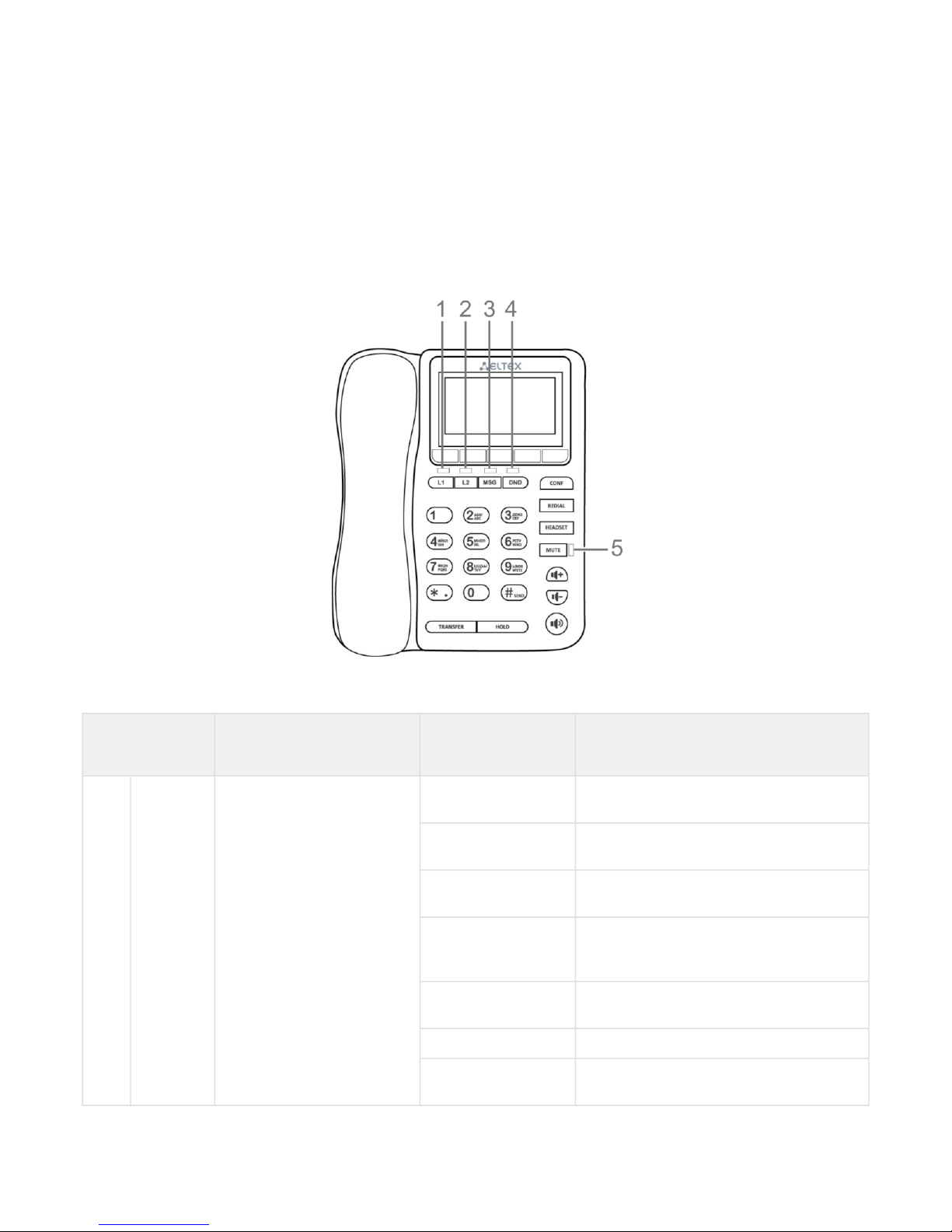
The figure below shows VP-12(P) top panel layout
VP-12(P) top panel is equipped with LED indicators:
Front panel
element
Description LED state Device state
1, 2 L1, L2 Status indicators of the first
and second lines
off The account is registered and is in waiting
mode of incoming/outgoing call
solid green The account is active and is in the
conversation/dial mode
flashes green
(in standby mode)
The account is in the registration process
flashes green
(during conversation)
The second incoming call, incoming call on
the second line, one or more calls are on
hold
flashes green (during
incoming call)
Incoming call
solid red Registration error
solid orange The account is in the DND (do not disturb)
mode
Page 11
VP-12, VP-12P IP phones. Operation manual
11
Front panel
element
Description LED state Device state
3 MSG Voice message indicator
off There are no unread messages
flashes red There are unread messages
4 DND Indicator of the DND service
status
flashes red DND mode is activated on at least one
account
off DND mode is not activated
5 MUTE Indicator of disabled mic
solid red Mute mode is activated for the current
conversation
off Mute mote is not activated
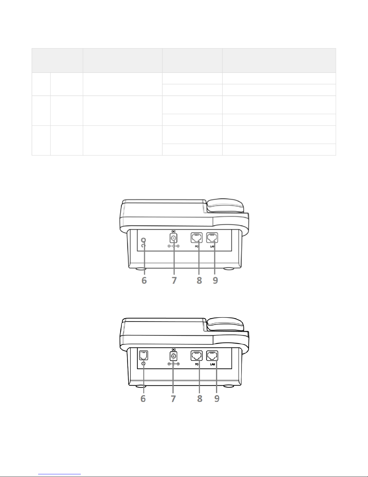
1.4.2 Rear panel of the device
VP-12(P) rear panel layout depends on hardware version. Figure A shows the layout for versions below 2.0, Figure B
shows the layout for version 2.0 and later ones.
Figure А –VP-12(P) rear panel layout for hardware versions below 2.0
Figure B–VP-12(P) rear panel layout for hardware version 2.0 and later
Page 12
VP-12, VP-12P IP phones. Operation manual
12
Rear panel layout Description
6 Headset Port for connecting a headset:
• for hardware versions below 2.0 – 3.5 mm port
• for version 2.0 and later – RJ-9 (4P4C) port
7 DC port for power adapter connection, 5V 2A
8 PC 10/100BASE-T Ethernet port (RJ-45 port) for connection to PC
9 LAN 10/100BASE-T Ethernet port (RJ-45 port) for connection to LAN
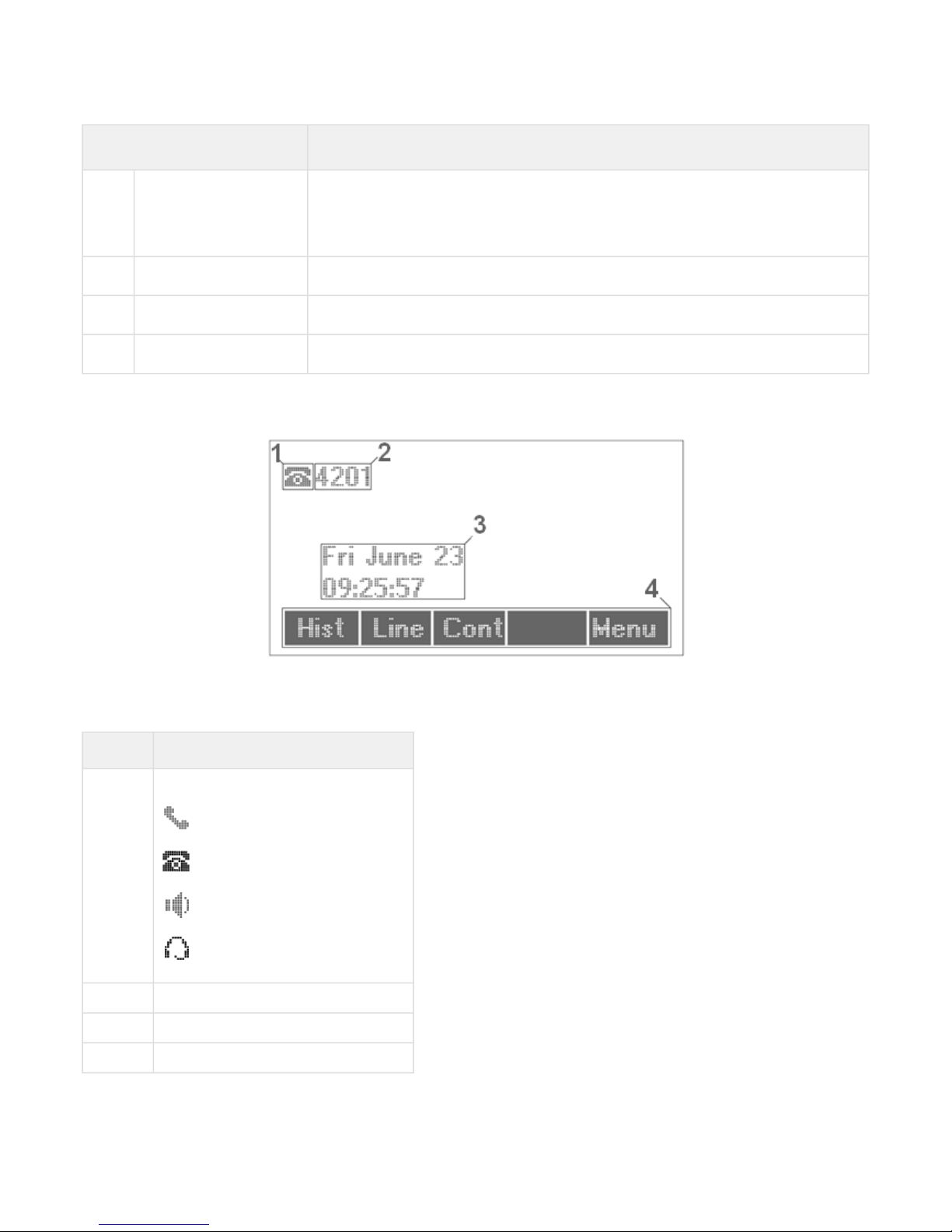
1.5 Status indication on graphic display
Indication status on graphic display
Number Description
1
Indicator of voice interface:
– handset is off-hook;
– handset is on-hook;
– speakerphone is activated;
– headphones are activated.
2 Phone number of the current account
3 Current date and time
4 Actions taken upon pressing soft-keys
Page 13

VP-12, VP-12P IP phones. Operation manual
13
1.6 Delivery package
VP-12(P) standard delivery package includes:
• Universal subscriber terminal(+handset and cable for handset connection);
• 220/5V 2А power adapter;
• RJ-45 cable;
• Quick user manual and warranty certificate.
A headphones might be added to delivery package upon a request
Page 14
VP-12, VP-12P IP phones. Operation manual
14
2 Managing VP-12(P) via web interface
2.1 Getting started
• Pre-starting procedures
• Web interface description
• Web interface operation modes
• Key elements of web interface
• Applying configuration
• Discarding changes
2.1.1 Pre-starting procedures
To start the operation, you should connect the device to PC via LAN interface. Use a web browser:
1. Open web browser, i.e Firefox,Opera,Chrome.
2. Enter the device IP address in the browser address bar.
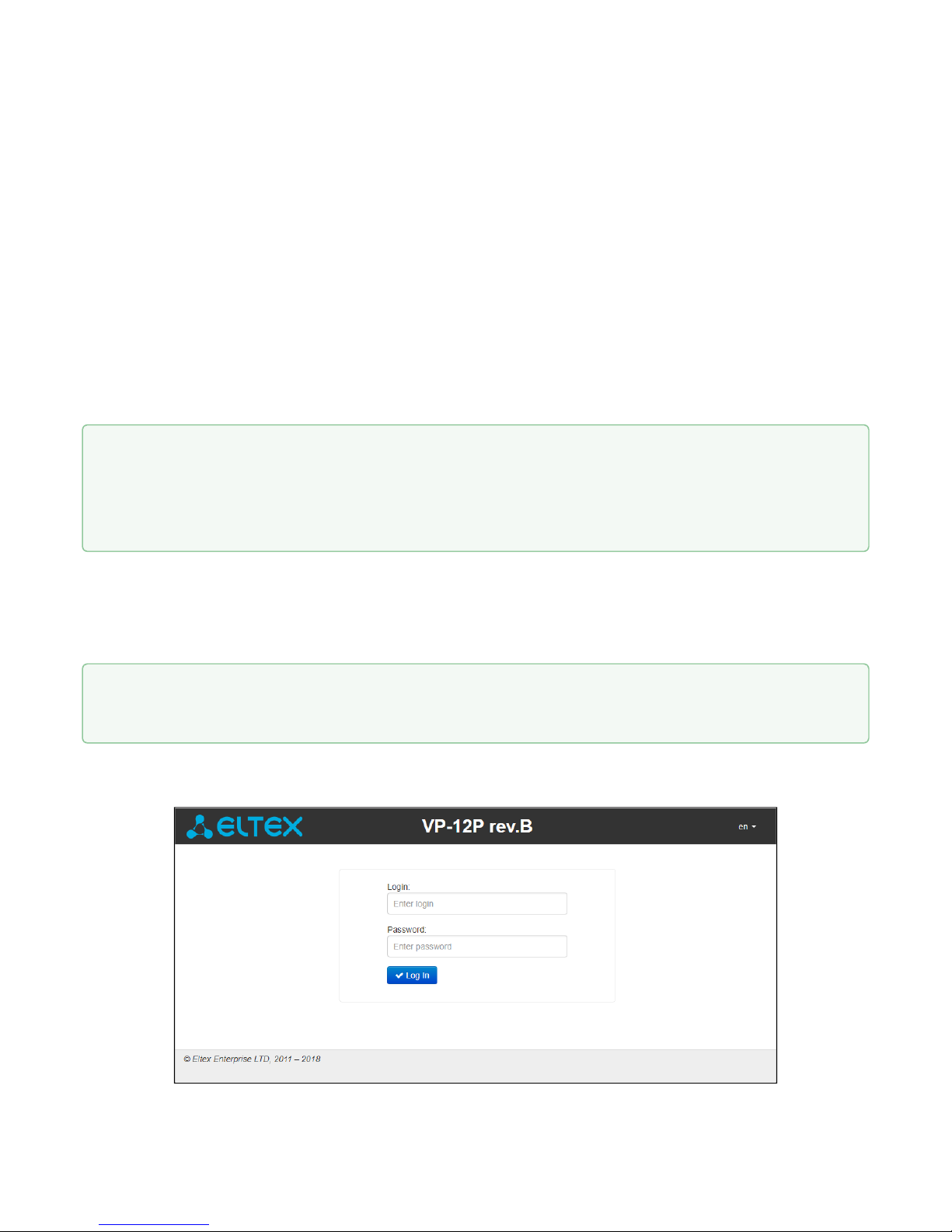
When the device is successfully detected, username and password request page will be shown in the browser
window:
It is recommended to reset the device to factory settings when switching it on for the first time. Use
display menu and buttons to reset the device – implement the following:
Menu -> 3. Settings -> 2. System -> 5. Reset settings -> Yes
The device will automatically reload.
By default, IP phone receives an IP address and other network parameters via DHCP.
To get an obtainedIP address, implement Menu -> 1. Statususing display menu.
Page 15

VP-12, VP-12P IP phones. Operation manual
15
3. Enter your username into 'Login' field and password into 'Password' field.
4. Click 'Log in' button. Monitoring panel will be shown in the browser.
2.1.2 Web interface description
2.1.2.1 Web interface operation modes
Web interface of the VP-12(P) device can operate in two modes:
• Configuration– a system mode which enables full device configuration. The mode has three tabs:
Network, VoIP and System.
• Monitoring– system monitoring mode–allows you to view various device operation information:
Internet connection activity, phone port status, amount of received/sent data via network interfaces, etc.
2.1.2.2 Key elements of web interface
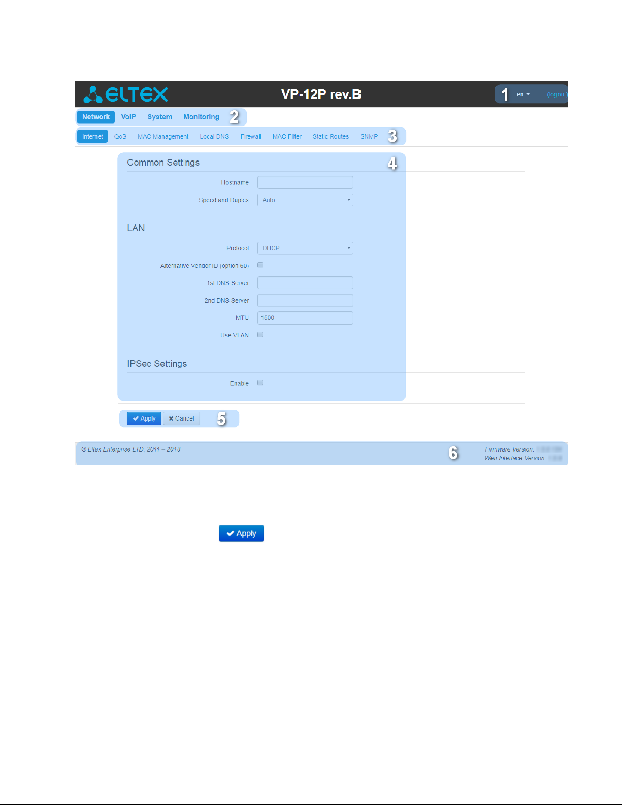
User interface window is divided into 6 areas(see figure "Key elements of web interface"):
1. User name for log in, session termination button in the web interface ('Sign Out') for the current user
and dropped down menu for changing language.
2. Menu tabs allow you to select configuration and monitoring categories: Network, VoIP, System,
Monitoring.
3. Submenu tabs allow you to control settings field.
4. Device settings field based on the user selection; allows you to view device settings and enter
configuration data.
5. Configuration management buttons. For detailed description seeApplying configuration.
• Apply–apply and save the current configuration into flash memory of the the device;
• Discard– discard changes (effective only until 'Apply' button is clicked).
6. Informational field showing firmware version and web interface version.
By default, username – admin, password – password
Before you start, please, update the software. See section «Firmware upgrade» submenu.
You may download the up-to-date firmware version on the Downloads page or contact Eltex technical
support. You may find contacts on TECHNICAL SUPPORT page.
Page 16
VP-12, VP-12P IP phones. Operation manual
16
Main elements of web configurator
2.1.2.3 Applying configuration
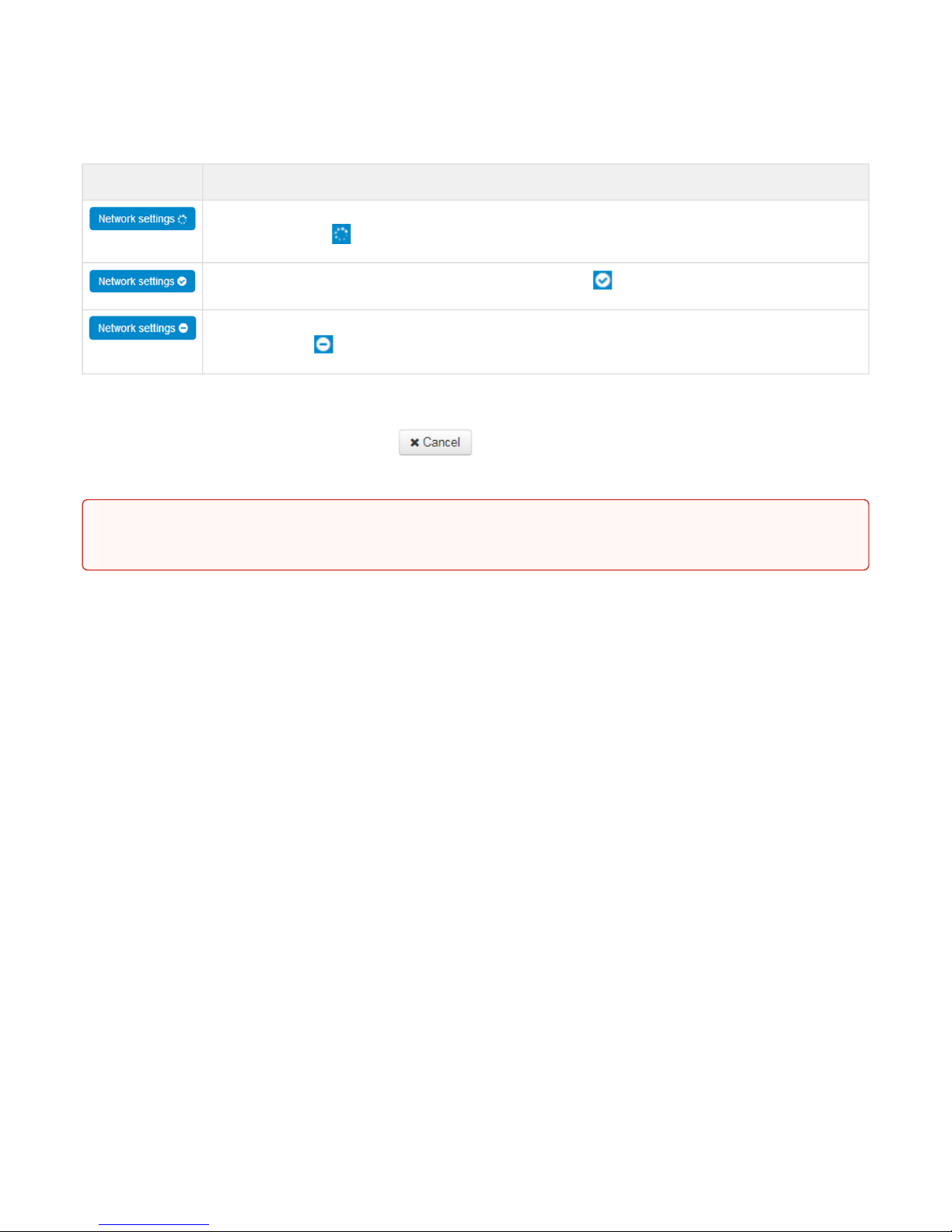
«Apply» button appears as follows: .Click it to save the configuration into the device flash memory
and apply new settings. All settings will be accepted without device restart.
See the following table for detailed information on web interface visual indication of the status of settings
application process:
Page 17
VP-12, VP-12P IP phones. Operation manual
17
Visual indication of the current status of the setting application process
Appearance Status description
When you click the 'Accept' button, settings will be applied and stored into the device memory.This
is indicated by the icon in the tab name and on the 'Apply' button.
Successful settings saving and application are indicated by .
If the parameter value being specified contains an error, you will see a message with the reason
description and .
2.1.2.4 Discarding changes
Discard changes button appears as follows: .Clickit torestorevalues currently stored in the device
memory.
icon in the tab name
icon will appear in the tab name, when you click 'Apply' button
Use «Cancel» button before clicking «Apply» button. After you click «Apply», you will not be able to
restore the previous settings.
Page 18

VP-12, VP-12P IP phones. Operation manual
18
2.2 Configuring VP-12(P)
To move to configuration mode, choose one of the following tab «Network», «VoIP» or «System» depending on
the configuration goals:
• «Network» menu is dedicated to implement network settings configuration.
• «VoIP» menu is dedicated to implementthe following configuration: SIP settings, accounts settings,
codecs installation, VAS and dialplan settings.
• «System» menu is dedicated to configure system time, access to the device via different protocols,
change passwords, update firmware.
Configuration mode elements:
• «Network» menu
• «Internet» submenu
• «QoS» submenu
• «MAC management» submenu
• «Local DNS» submenu
• «Firewall» submenu
• «MAC filter» submenu
• «Static Routes» submenu
• «SNMP» submenu
• «VoIP» menu
• «Network settings» submenu (VoIP)
• «SIP Accounts» submenu
• «Common SIP settings» submenu
• «QoS» submenu
• «Phone Book» submenu
• «Call history» submenu
• «System» menu
• «Time» submenu
• «Access» submenu
• «Log» submenu
• «Password» submenu
• «Configuration Management» submenu
• «Firmware upgrade» submenu
• «Reboot» submenu
• «Autoprovisioning» submenu
• «Management interface» submenu
• «Certificates» submenu
• «Advanced» submenu
Page 19
VP-12, VP-12P IP phones. Operation manual
19
2.2.1 «Network» menu
«Network» menu is dedicated to implement network settings configuration.
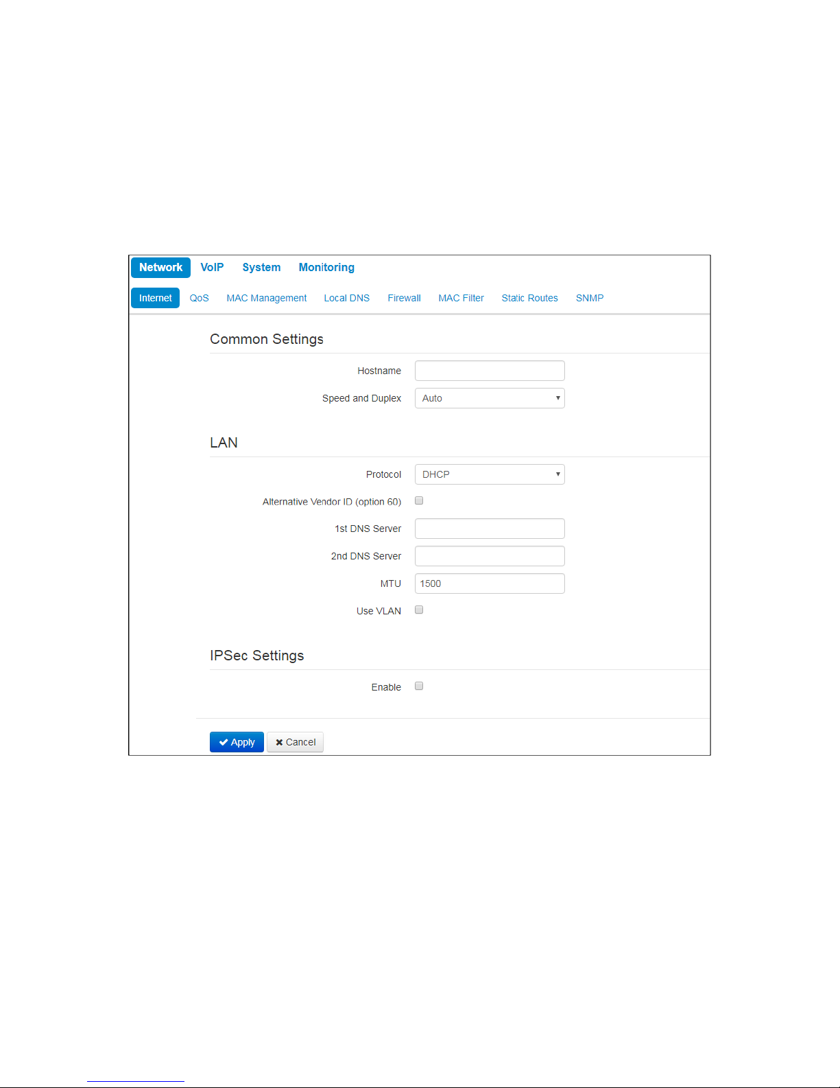
2.2.1.1 «Internet» submenu
In the 'Internet' submenu you may configure LAN (via PPPoE, DHCP, and Static).
Common settings
• Hostname – device network name.
• Speed and Duplex–specify data rate and duplex mode for LAN Ethernet port of the device:
• Auto– automatic speed and duplex negotiation;
• 100 Half –100Mbps data transfer rate with half-duplex mode is supported;
• 100 Full –100Mbps data transfer rate with duplex mode is supported;
• 10 Half –10Mbps data transfer rate with half-duplex mode is supported;
• 10 Full–10Mbps data transfer rate with duplex mode is supported.
Page 20

VP-12, VP-12P IP phones. Operation manual
20
LAN
• Protocol– select the protocol that will be used for device LAN interface connection to provider network:
• Static– operation mode where IP address and all the necessary parameters for LAN interface are
assigned statically;
• DHCP– operation mode where IP address, subnet mask, DNS address, default gateway and other
necessary settings for network operation are automatically obtained from DHCP server.;
• PPPOE– operation mode when PPP session is established on LAN interface.
Static
When 'Static' type is selected, the following parameters will be available for editing:
• IPAddress – specify the device LAN interface IP address in the provider network;
• Netmask– external subnet mask;
• Default gateway– address that the packet will be sent to, when route for it is not found in the routing
table;
• 1st DNS Server,2nd DNS Server– domain name server addresses (allow identifying the IP address of the
device by its domain name).You may leave these fields empty, if they are not required.
• MTU–maximum size of the data unit transmitted on the network.
DHCP
When 'DHCP' type is selected, the following parameters will be available for editing:
• Alternative Vendor ID (Option 60)–when selected, the device transmits Vendor ID (Option 60) field value
in Option 60 DHCP messages (Vendor class ID).If the field is empty, Option 60 will not be transmitted in
DHCP messages:
[VENDOR:device vendor][DEVICE:device type][HW:hardware version] [SN:serial number][WAN:WAN
interface MAC address][LAN:LAN interface MAC address][VERSION:firmware version]
Example:[VENDOR:Eltex][DEVICE:VP-12P][HW:1.0][SN:VI23000118] [WAN:A8:F9:4B:03:2A:D0][LAN:
02:20:80:a8:f9:4b][VERSION:#1.1.0]
• VendorID(Option 60) – option 60 value (VendorclassID) which is transmitted in DHCP messages.
When the field is empty, option 60 is not transmitted in DHCP messages.
• 1st DNS Server,2nd DNS Server– domain name server addresses (allow identifying the IP address of the
device by its domain name. Addresses, which are specified statically, have the higher priority than
addresses obtained via DHCP.
• MTU– maximum size of the data unit transmitted on the network.
You can manually assign the List of used DHCP options on each network interface (Internet, VoIP, and
Management). See AppendixDHCP client configuration in multiservice mode.
PPPoE
When 'PPPoE' type is selected, the following parameters will be available for editing:
• User Name– username for authorization on PPP server.
• Password– password for authorization.
• MTU– maximum size of the data unit transmitted on the network(recommended value– 1492).
• Service-Name–service-Name tag value in PADI message (this field is optional)/
• Secondary access– type of access (IPOE) to local area network resources. You may select 2 options:
• DHCP – dynamic access when IP address and other required parameters are obtained via DHCP;
Page 21

VP-12, VP-12P IP phones. Operation manual
21
• Static – specifying access settings manually: IP address, subnet mask, DNS server, gateway;
• Use the Secondary Access for VoIP– this option is available, if there are no dedicated interfaces for VoIP
service ('Use Internet settings' checkbox is selected). When the checkbox is not selected (default value),
VoIP service uses PPP interface for its operation; when selected, the secondary access interface (IPoE).
• Alternative Vendor ID (Option 60)–when selected, the device transmits Vendor ID (Option 60) field value
in Option 60 DHCP messages (Vendor class ID).If the field is empty, Option 60 will not be transmitted in
DHCP messages:
[VENDOR:device vendor][DEVICE:device type][HW:hardware version] [SN:serial number][WAN:WAN
interface MAC address][LAN:LAN interface MAC address][VERSION:firmware version]
Example:[VENDOR:Eltex][DEVICE:VP-12P][HW:1.0][SN:VI23000118] [WAN:A8:F9:4B:03:2A:D0][LAN:
02:20:80:a8:f9:4b][VERSION:#1.1.0]
• VendorID(Option 60) – option 60 value (VendorclassID) which is transmitted in
DHCP messages. When the field is empty, option 60 is not transmitted in DHCP
messages.
Use VLAN
VLAN – a virtual local area network. VLAN is a group of hosts united in a network not depending on the
physical location. The devices grouped to a VLAN have the same identifier VLAN-ID.
• Use VLAN– use VLAN identifier specified below to enter the network.
• VLAN ID– VLAN identifier which is used for the device.
• 802.1P– 802.1P attribute (also called CoS – Class of Service) is attached to egress IP packets.
The value is from 0 (the least priority) to 7 (the highest priority).
When you choose one of the way of IP addresses assignment, the addiitonal parameters
will be displayed according to the selected protocol.
Page 22
VP-12, VP-12P IP phones. Operation manual
22
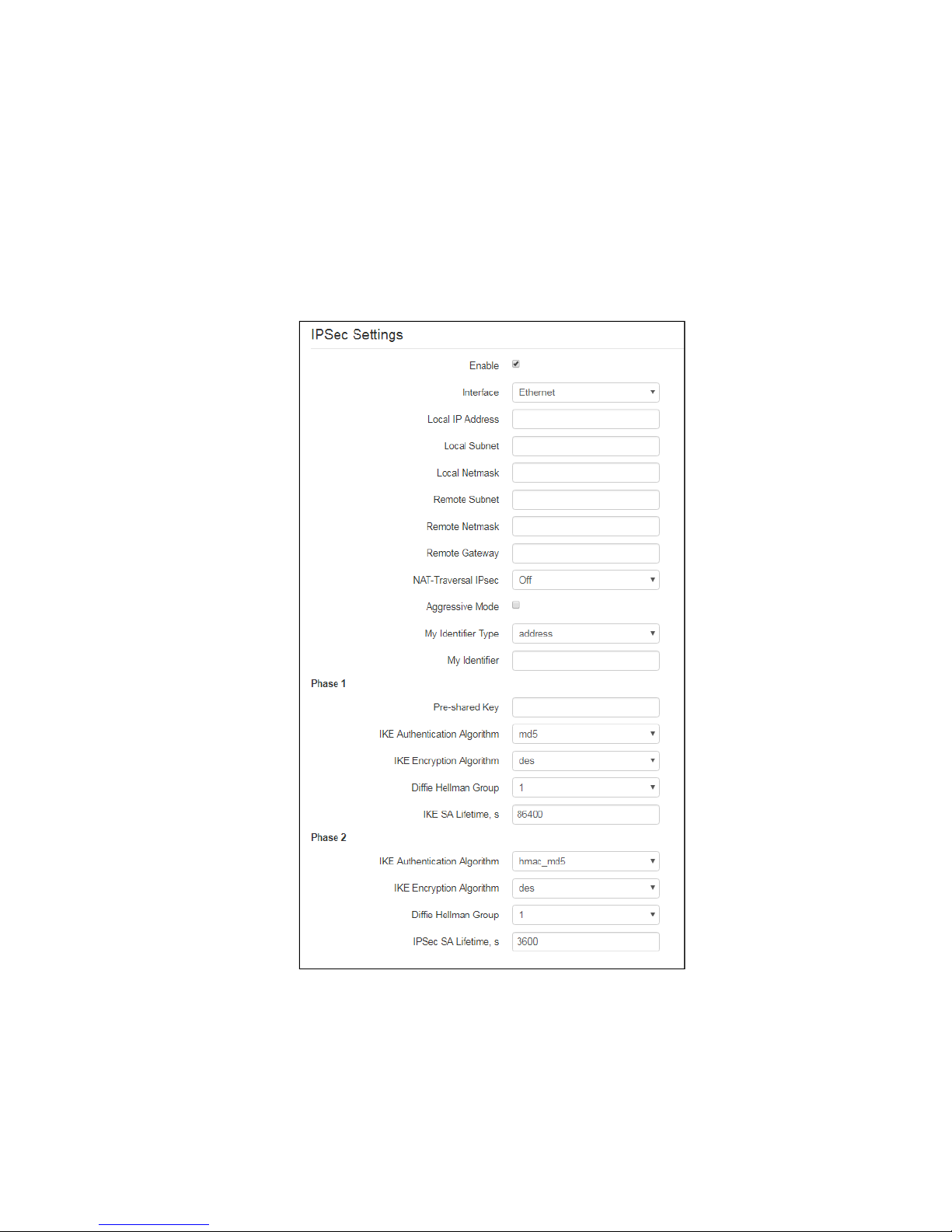
IPsec settings
In this section you may configure IPSec encryption (IP Security).
IPSec is a set of protocols used for protection of data transmitted via Internet Protocol that enables
authentication, integrity check and/or encryption of IP packets. IPSec also includes secure Internet Key
Exchange protocols.
In the current firmware version you may only access the device management interfaces (Web, Telnet) using
IPsec.
• Enable– enable IPSec protocol utilization for data encryption;
• Interface– this setting takes effect only when PPPoE is selected for the Internet, and defines the
interface that will be accessed with IPSec: Ethernet (secondary access interface) or PPP (primary
access interface). When DHCP or Static protocol is selected, there is only a single active interface
(Ethernet) for the service that may be accessed with IPSec only;
Page 23

VP-12, VP-12P IP phones. Operation manual
23
• Local IP Address– device address for IPSec operation;
• Local Subnettogether with aLocal Netmaskdefine a local subnet for creation of network-to-
network or network-to-point topologies;
• Remote Subnettogether with aRemote Netmaskdefine a remote subnet address used for IPSec-
encrypted communication. If the mask value is 255.255.255.255, communication is performed
with a single host. Mask that differs from 255.255.255.255 allows you to define a whole subnet.
Thus, device features allow you to establish 4 network topologies that utilize IPSec traffic
encryption: Point-to-Point, Network-to-Point, Point-to-Network, Network-to-Network;
• Remote gateway– gateway used for remote network access;
• NAT-Traversal IPsec –NAT-T mode selection. NAT-T (NAT Traversal) encapsulates IPSec traffic
and simultaneously creates UDP packets to be sent correctly by a NAT device. For this purpose,
NAT-T adds an additional UDP header before IPSec packet so it would be processed as an
ordinary UDP packet and the recipient host would not perform any integrity checks. When the
packet arrives to the destination, UDP header is removed and the packet goes further as an
encapsulated IPSec packet. With NAT-T technique you may establish communication between
IPSec clients in secured networks and public IPSec hosts via firewalls. NAT-T operation modes:
• On– NAT-T mode is activated only when NAT is detected on the way to the
destination host;
• Force– use NAT-T in any case;
• Off– disable NAT-T on connection establishment.
The following NAT-T settings are available:
• NAT-TUDP port–UDP port for packets for IPSec message encapsulation. Default
value is 4500.
• Interval Between Sending NAT-T Keepalive Packets, s– periodic message
transmission interval for UDP connection keepalive on the device performing NAT
functions.
• Aggressive Mode– phase 1 operation mode when all the necessary information is
exchanged using three unencrypted packets. In the main mode, the exchange process
involves six unencrypted packets.
• My Identifier Type– device identifier type: address, fqdn, keyed, user_fqdn, asn1dn;
• My Identifier– device identifier used for identification during phase 1 (fill in, if required). Identifier format
depends on the type.
Phase1
During the first step (phase), two hosts negotiate on the identification method, encryption algorithm, hash
algorithm and Diffie Hellman group. Also, they identify each other. For phase 1, there are the following settings:
• Pre-shared Key– a secret key used by authentication algorithm in phase 1. It is represented by a string
from 8 to 63 characters.
• IKE Authentication Algorithm–select an authentication algorithm from the list: MD5, SHA1.
• IKE Encryption Algorithm– select an encryption algorithm from the list : DES, 3DES, Blowfish.
• Diffie Hellman Group–select an Diffie-Hellman group.
• IKE SA Lifetime, s– time that should pass for hosts' mutual re-identification and policy comparison
(other name 'IKE SA lifetime'). Default value is 24 hours (86400 seconds).
Page 24
VP-12, VP-12P IP phones. Operation manual
24
Phase2
During the second step, key data is generated; hosts negotiate on the utilized policy. This mode—also called as
'quick mode'—differs from the phase 1 in that it may be established after the first step only, when all the phase
2 packets are encrypted.
• IKE Authentication Algorithm– select an authentication algorithm from the list: HMAC - MD5, HMAC-
SHA1, DES, 3DES;
• IKE Encryption Algorithm– select an encryption algorithm from the list: DES, 3DES, Blowfish;
• Diffie Hellman Group– select Diffie-Hellman group;
• IPSec SA Lifetime, s– time that should pass for the data encryption key changeover (other name 'IPSec
SA lifetime'). Default value is 60 minutes (3600 seconds).
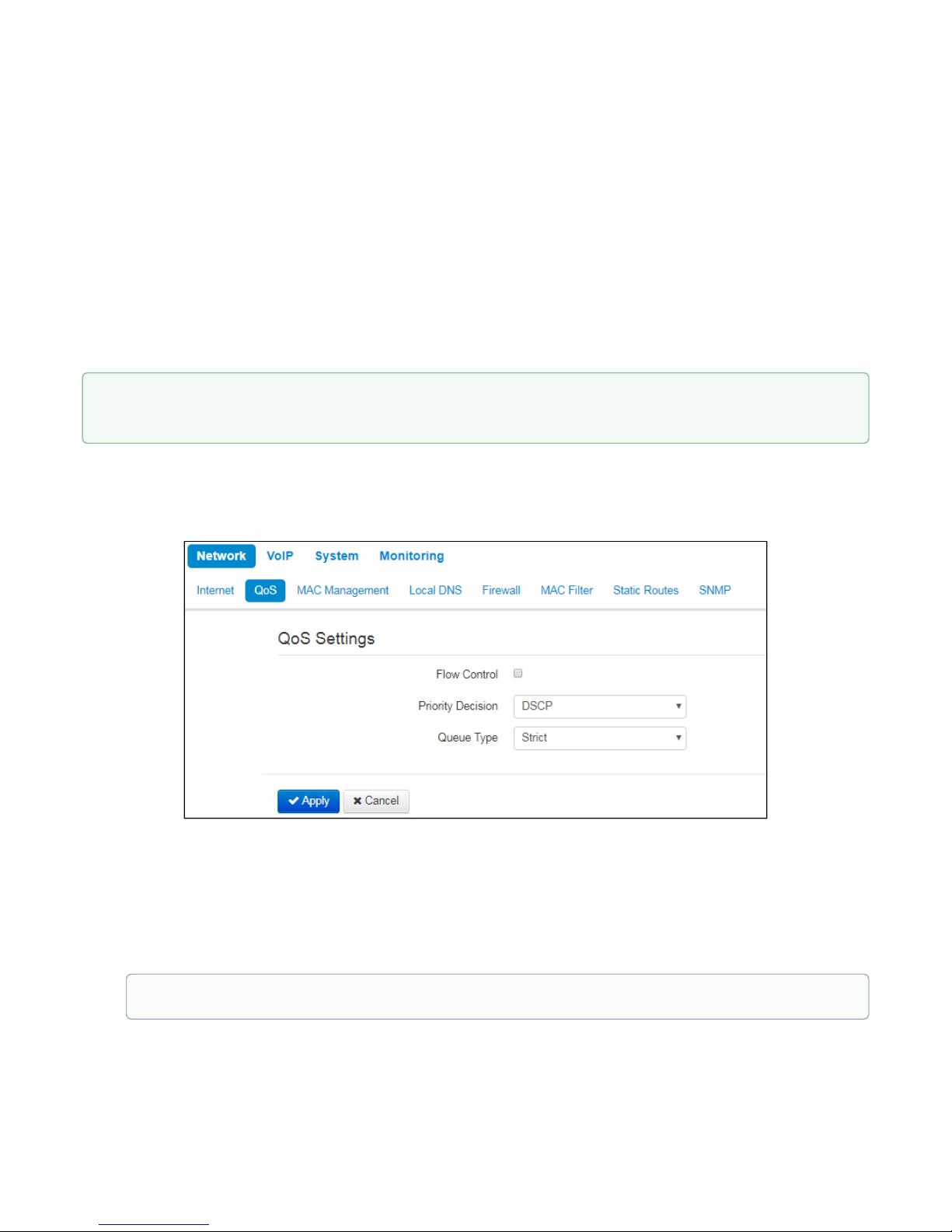
2.2.1.2 «QoS» submenu
In the 'QoS' submenu you may configure traffic processing priority and queue type.
• Flow control– enabling/disabling a mechanism of data flow management by using TCP;
• Priority decision–select traffic prioritization way:
• DSCP– classification mechanism of traffic control and providing quality of service by priorities;
• 802.1p –attribute(CoS – Class of Service) is attached to egress IP packets. The value is from 0
(the least priority) to 7 (the highest priority).
• Queue type–select service procedure of queues:
• Strict– service procedure of queues when traffic with lowest priority is transmitted only after
transmitting queues with higher priority;
To apply a new configuration and store settings into the non-volatile memory, click 'Apply' button. To
discard changes, click 'Cancel' button.
Settings of the priorities are not available when flow control is enabled.
Page 25
VP-12, VP-12P IP phones. Operation manual
25
• WRQ– service procedure of queues, when accessible bandpass is devided among queues in
propotion with priority.
• Weight 0..5 –define priority weight in the range from 1 to 127. Then weight is higher
then traffic is more priority.
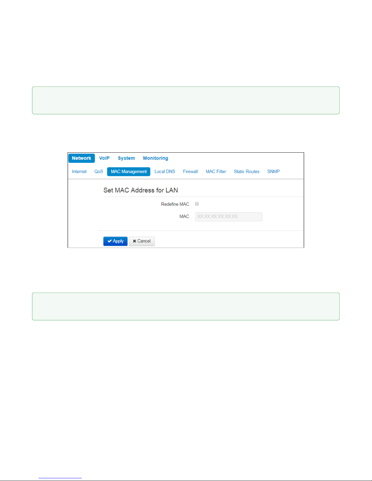
2.2.1.3 «MAC management» submenu
In the 'MAC management' submenu you may change MAC address of the device LAN interface.
• Redefine
МАС
– when selected, MAC address from the MAC field is used on the Internet interface.
• MAC–MAC address that will be assigned to the device network interface.
To redefine MAC for 'VoIP' or 'Management VLAN' interface, use sections 'Set MAC address for interface 'VoIP''
or 'Set MAC address for interface 'Management VLAN''.
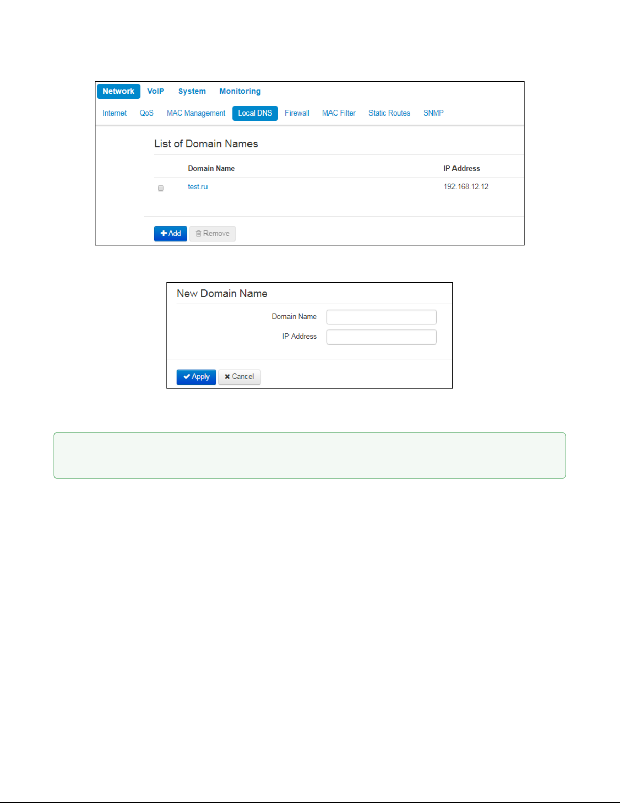
2.2.1.4 «Local DNS» submenu
In 'Local DNS' submenu you may configure a local DNS server by adding 'IP address – domain name' pairs into
the database.
Local DNS allows the gateway to obtain IP address of the communicating device by its domain name. You may
use local DNS in cases when DNS server is missing from the network segment that the gateway belongs to,
and you need to establish routing using network names, or when you have to use SIP server network name as
its address. Although, you have to know the matches between hostnames (domains) and their IP addresses.
To apply a new configuration and store settings into the non-volatile memory, click 'Apply' button. To
discard changes, click 'Cancel' button.
To apply a new configuration and store settings into the non-volatile memory, click 'Apply' button. To
discard changes, click 'Cancel' button.
Page 26
VP-12, VP-12P IP phones. Operation manual
26
To add the address into the list, click 'Add' button in the 'New domain name' window and fill in the following
fields:
• Domain name– host name;
• IP address–host IP address.
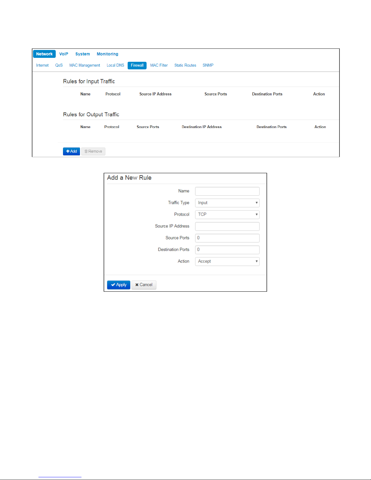
2.2.1.5 «Firewall» submenu
In the 'Firewall' submenu you may set the rules for the incoming, outgoing, and transit traffic transmission. You
may restrict transmission of various traffic types (incoming, outgoing, transit) depending on the protocol,
source and destination IP addresses, source and destination TCP/UDP ports (for TCP or UDP messages),
ICMP message type (for ICMP messages).
Click 'Apply' to create 'IP address—domain name' pair. To discard changes, click 'Cancel' button. To
remove the record from the list, select the checkbox next to the respective record and click 'Delete'.
Page 27
VP-12, VP-12P IP phones. Operation manual
27
To add a new rule, click 'Add' button and fill in the following fields in the 'Add a New Rule' window:
• Name– rule name.
• Traffic Type– select traffic type to which this rule will apply:
• Input –incoming device traffic (recipient is one of the device network interfaces);
• Output– outgoing device traffic (traffic generated locally by the device from one of the network
interfaces).
• Source IP Address–define starting source IP address. Use '/' symbol to define a
mask in 'xxx.xxx.xxx.xxx' or 'xx' format, e.g. 192.168.16.0/24 or
192.168.16.0/255.255.255.0, when you need to specify an address range (/24 mask
record corresponds to /255.255.255.0).
• Destination IP Address–define destination IP address. Use '/' symbol to define a
subnet mask in 'xxx.xxx.xxx.xxx' or 'xx' format, e.g. 192.168.18.0/24 or
192.168.18.0/255.255.255.0, when you need to highlight an address range.
• Protocol– packet protocol to which this rule will apply:
• TCP;
• UDP;
• TCP/UDP;
• ICMP;
• Any.
Page 28
VP-12, VP-12P IP phones. Operation manual
28
• Action– an action to be performed on packets (reject/skip).
When TCP, UDP, TCP/UDP are selected, the following settings will become available for editing:
• Source ports– list of source ports with packets falling under the rule (a single port or port range
delimited by '-' is permitted).
• Destination ports– list of destination ports. The packets of a destination port fall under this rule (a single
port or port range delimited by '-' is permitted).
When ICMP protocol is selected, the following setting will be available for editing:
• Message type–you may create a rule for the specific ICMP message type only or for all ICMP message
types..
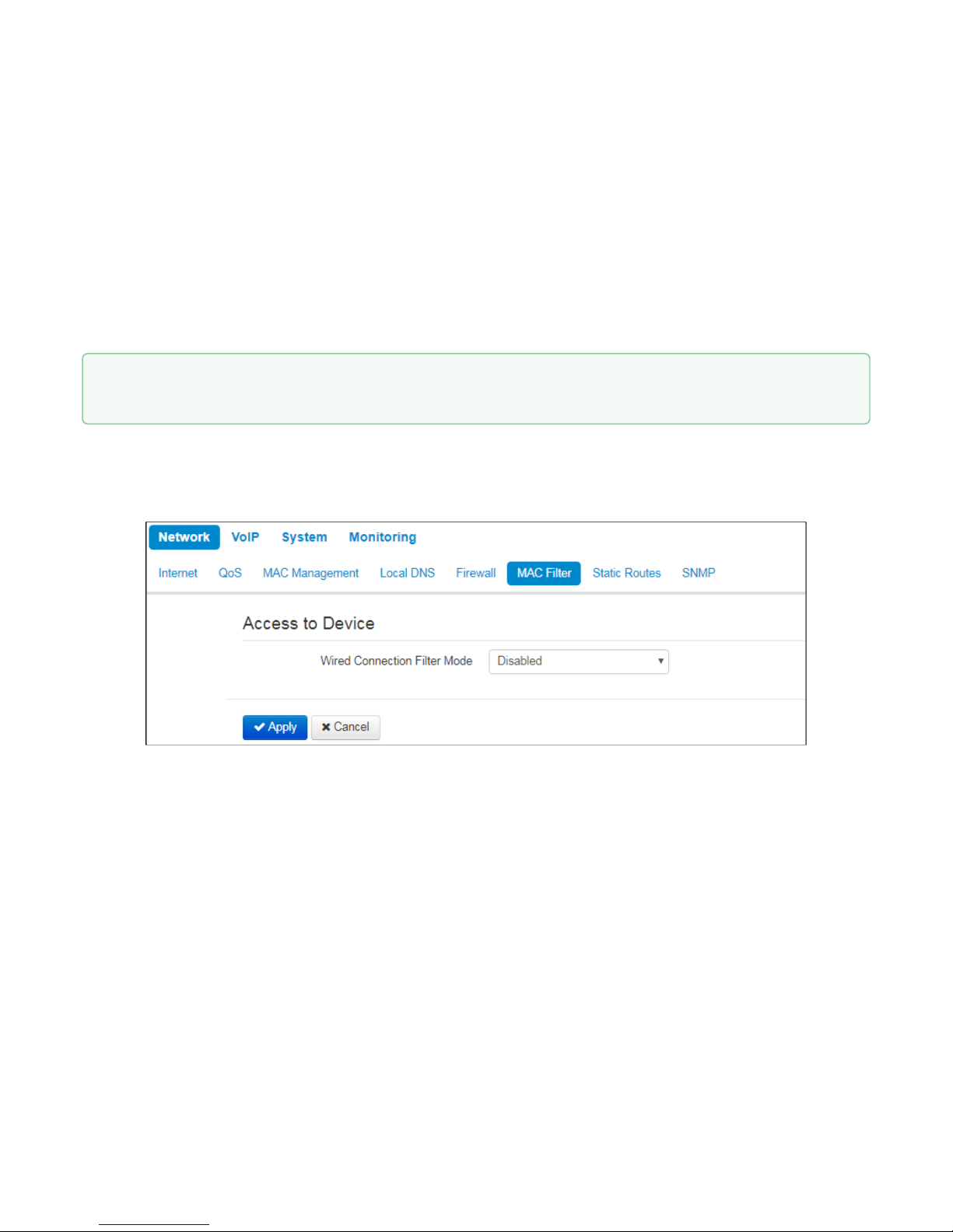
2.2.1.6 «MAC filter» submenu
In the 'MAC filter' submenu, you may configure access filtering by client's MAC address.
Wired Connection Filter Mode– define one of the three filter operation modes depending on the client's
MAC address:
• Disabled–MAC address filtering is disabled, all clients are allowed to connect to the device;
• Deny– in this filter operation mode, clients with MAC addresses from the 'MAC address list' are
denied to connect to the device. Subscribers with unlisted MAC addresses are allowed to connect
to the device;
• Allow– in this filter operation mode, clients with MAC addresses from the 'MAC address list' are
allowed to connect to the device. Subscribers with unlisted MAC addresses are denied to connect
to the device.
Click 'Apply' button to add a new rule. To discard changes, click 'Cancel' button. To remove the record
from the list, select the checkbox next to the respective record and click 'Delete'.
Page 29
VP-12, VP-12P IP phones. Operation manual
29
MAC address list
You may enter up to 30 client MAC addresses which may access the device in accordance to the specified
filtering mode.
To add a new client to the list, click 'Add' button and enter its MAC address.
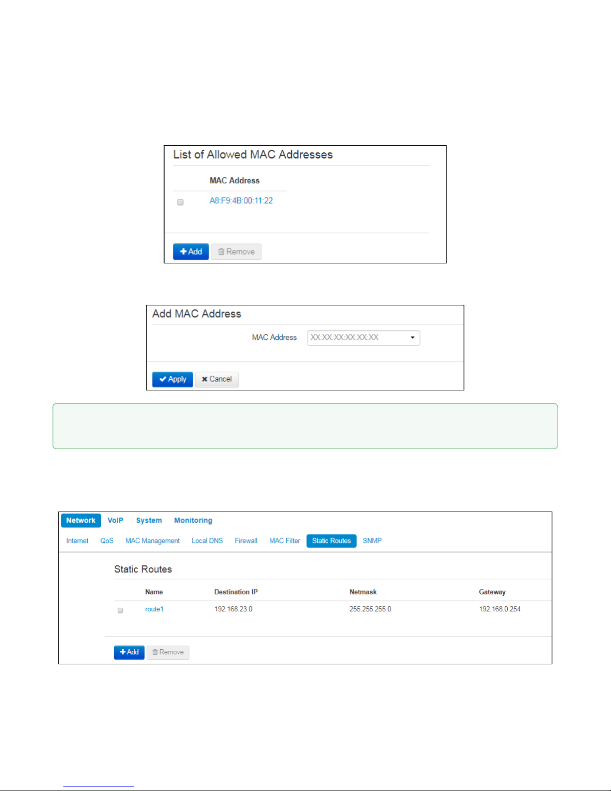
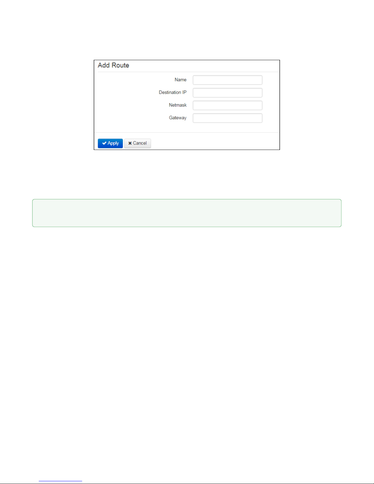
2.2.1.7 «Static Routes» submenu
In the 'Static routes' submenu you may configure device static routes.
To apply a new configuration and store settings into the flash memory, click 'Apply' button. To discard
changes, click 'Cancel' button.
Page 30
VP-12, VP-12P IP phones. Operation manual
30
To add a new route, click 'Add' button and fill in the following fields:
• Name– route name, used for human perception convenience. You may leave this field empty;
• Destination IP–IP address of destination host or subnet that the route should be established to;
• Netmask– subnet mask. Subnet mask for host should be 255.255.255.255, for subnet—depending on
its size;
• Gateway–gateway IP address that allows for the access to the 'Destination IP'.
To apply a new configuration and store settings into the non-volatile memory, click 'Apply' button. To
discard changes, click 'Cancel' button.
Page 31

VP-12, VP-12P IP phones. Operation manual
31
2.2.1.8 «SNMP» submenu
VP-12(P) software allows you to monitor status of the device and configure it via SNMP protocol. In SNMP
submenu, you can configure settings of SNMP agent. Device supports SNMPv1, SNMPv2c protocol versions.
• Enable SNMP–when checked, SNMP will be enabled for utilization;
• roCommunity–password for parameter reading (common: public).
• rwCommunity–password for parameter writing (common: private).
• TrapSink– IP address or domain name of SNMPv1-trap message receiver in HOST [COMMUNITY
[PORT]] format.
• Trap2Sink–IP address or domain name of SNMPv2-trap message receiver in HOST [COMMUNITY
[PORT]] format.
• InformSink–IP address or domain name of Inform message receiver in HOST [COMMUNITY [PORT]]
format.
• Sys Name–device name;
• Sys Contact–device vendor contact information;
• Sys Location–device location information;
• Trap Community–password in traps (by default trap).
To store settings into the non-volatile memory, click 'Apply' button. To discard changes, click 'Cancel'
button.
Page 32

VP-12, VP-12P IP phones. Operation manual
32
2.2.2 «VoIP» menu
In the 'VoIP' menu you may configure VoIP (Voice over IP): SIP protocol configuration, account configuration,
installation of codecs, VAS and dial plan.
2.2.2.1 «Network settings» submenu (VoIP)
In the "VoIP' menu – 'Network Settings' submenu you may specify custom network settings for VoIP service.
• Use Internet Settings– when selected, use network settings specified in the 'Network' -> 'Internet' menu,
otherwise use settings specified in this menu;
VLAN settings
• UseVLAN– when selected, VoIP service will use a dedicated interface in a separate VLAN for its
operation, with VLAN number specified in 'VLAN ID' field.
• VLAN ID– VLAN identifier which is used for the network interface.
• 802.1P –attribute(CoS – Class of Service)is attached to egress IP packets. The value is from 0 (the
least priority) to 7 (the highest priority).
Page 33

VP-12, VP-12P IP phones. Operation manual
33
Network settings
• Protocol– select protocol assigning address to VoIP service interface:
• Static– operation mode where IP address and all the necessary settings for LAN interface are
assigned manually. When 'Static' type is selected, the following parameters will be available for
editing.
• DHCP– operation mode where IP address, subnet mask, DNS address and other necessary
settings for service operation (e.g. SIP and registration server static routes) are automatically
obtained from DHCP server.
Static
When 'Static' type is selected, the following parameters will be available for editing:
• IPAddress –specify the device LAN interface IP address in the provider network;
• Netmask–external subnet mask;
• Default gateway–address that the packet will be sent to, when route for it is not found in the
routing table;
• 1st DNS Server,2nd DNS Server–domain name server addresses (allow identifying the IP address
of the device by its domain name).You may leave these fields empty, if they are not required.
• MTU–maximum size of the data unit transmitted on the network.
DHCP
When 'DHCP' type is selected, the following parameters will be available for editing:
• Alternative Vendor ID (Option 60)–when selected, the device transmits Vendor ID (Option 60) field
value in Option 60 DHCP messages (Vendor class ID).If the field is empty, Option 60 will not be
transmitted in DHCP messages:
[VENDOR:device vendor][DEVICE:device type][HW:hardware version] [SN:serial number]
[WAN:WAN interface MAC address][LAN:LAN interface MAC address][VERSION:firmware version]
Example:[VENDOR:Eltex][DEVICE:VP-12P][HW:1.0][SN:VI23000118] [WAN:A8:F9:4B:03:2A:D0]
[LAN:02:20:80:a8:f9:4b][VERSION:#1.1.0]
• VendorID(Option 60) – option 60 value (VendorclassID) which is transmitted in
DHCP messages. When the field is empty, option 60 is not transmitted in DHCP
messages.
• 1st DNS Server,2nd DNS Server–domain name server addresses (allow identifying the IP address
of the device by its domain name. Addresses, which are specified statically, have the higher
priority than addresses obtained via DHCP.
• MTU–maximum size of the data unit transmitted on the network.
You can manually assign the List of used DHCP options on each network interface (Internet, VoIP, and
Management). See AppendixDHCP client configuration in multiservice mode.
IPsec settings
In this section you may configure IPSec encryption (IP Security). IPSec is a set of protocols used for protection
of data transmitted via Internet Protocol that enables authentication, integrity check and/or encryption of IP
packets. IPSec also includes secure Internet Key Exchange protocols.
In the current firmware version you may only access the device management interfaces (Web and Telnet)
using IPSec.
Page 34

VP-12, VP-12P IP phones. Operation manual
34
For detailed information onIPSecsettings see «Internet» submenu sectionIPsec settings.
2.2.2.2 «SIP Accounts» submenu
Use drop-down 'SIP Accounts' menu to select account for editing.
You can assign own SIP server addresses, registration servers, voice codecs, individualized dialing plan and
other parameters for each account.
General settings
• Enable– when selected, account is active.
• Phone– subscriber number assigned to the account.
• User Name– user name associated with the account (shown in 'Display-Name' field of 'From' header in
the outgoing SIP messages).
To apply a new configuration and store settings into the non-volatile memory, click 'Apply' button. To
discard changes, click 'Cancel' button.
Page 35

VP-12, VP-12P IP phones. Operation manual
35
• Use Alternative Number–when selected, an alternative number will be inserted into the 'From' header of
SIP messages sent from this account (particularly, in order to hide the real number from the Caller ID
system of the callee).
• Use As a Contact Header–alternative number assigned to a phone port will be changed to
specified number and inserted into 'Contact' header of the SIP message.
• SIP Port–UDP port for incoming SIP message reception for this account, and for outgoing SIP message
transmission from this account. It may take values from 1 to 65535 (default value: 5060).
• Calling Party Category–enables transmission of outgoing messages in the 'From' header; the last
header is transmitted in Tel-URI format (see RFC3966).
Authentication
• Login– user nameused for subscriber authentication on SIP server (and on registration server).
• Password– password used for subscriber authentication on SIP server (and on registration server).
SIP parameters
Use 'SIP Parameters' section to configure SIP parameters of the account.
• Proxy Mode–you can select SIP server operation mode in the drop-down list:
• Off;
• Parking – SIP-proxy redundancy mode without main SIP-proxy management;
• Homing – SIP-proxy redundancy mode with main SIP-proxy management.
Page 36

VP-12, VP-12P IP phones. Operation manual
36
The phone may operate with a single main SIP-proxy and up to four redundant SIP-proxies. For
exclusive operations with the main SIP-proxy, 'Parking' and 'Homing' modes are identical. In this case,
if the main SIP-proxy fails, it will take time to restore its operational status.
For operations with redundant SIP-proxies, 'Parking' and 'Homing' modes will work as follows:
The gateway sends INVITE message to the main SIP-proxy address when performing outgoing call,
and REGISTER message when performing registration attempt. If on expiration of 'Invite total timeout'
there is no response from the main SIP-proxy or response 408 or 503 is received, the phone sends
INVITE (or REGISTER) message to the first redundant SIP-proxy address. If it is not available, the
request is forwarded to the next redundant SIP-proxy and so forth. When available redundant SIPproxy is found, registration will be renewed on that SIP-proxy.
Next, the following actions will be available depending on the selected redundancy mode:
In the 'parking' mode, the main SIP-proxy management is absent, and the phone will continue
operation with the redundant SIP-proxy even when the main proxy operation is restored. If the
connection to the current SIP-proxy is lost, querying of the subsequent SIP-proxies will be continued
using the algorithm described above. If the last redundant SIP-proxy is not available, the querying will
continue in a cycle, beginning from the main SIP-proxy.
In the 'homing' mode, three types of the main SIP-proxy management are available: periodic
transmission of OPTIONS messages to its address, periodic transmission of REGISTER messages to
its address, or transmission of INVITE request when performing outgoing call. First of all, INVITE
request is sent to the main SIP-proxy, and if it is unavailable, then the next redundant one, etc.
Regardless of the management type, when the main SIP-proxy operation is restored, the gateway will
use it to renew its registration. The gateway will begin operation with the main SIP-proxy.
• Proxy Server– network address of a SIP server—device that manages access to provider's phone
network for all subscribers. You may specify IP address as well as the domain name (specify SIP server
UDP port after the colon, default value is 5060).
• Registration–when selected, register ports that utilize this profile on registration server.
• Registration Server–network address of a device that is used for registration of all phone network
subscribers in order to provide them with the communication services (specify registration server UDP
port after the colon, default value is 5060). You may specify IP address as well as the domain name. As
a rule, registration server is physically co-located with SIP proxy server (they have the same address).
• Home Server Check Method– select availability control method for the primary SIP server in 'Homing'
mode:
• Invite –control via transmission of INVITE request to its address when performing an outgoing
call.
• Register –control via periodic transmission of REGISTER messages to its address.
• Options –control via periodic transmission of OPTIONS messages to its address.
• Home Server Keepalive Timeout, s– periodic message transmission interval in seconds; used for
primary SIP server availability check.
• Transport– select protocol for SIP messages transport.
• Invite Initial Timeout, ms– a time interval between first INVITE transmission and the second one in case
there is no answer on the first INVITE (ms). For the following INVITE requests (third, forth, fifth etc.) the
interval will be increased twice (i.e. if the value is 300 ms, the second INVITE will be sent in 300 ms, the
third – in 600 ms, the forth – in 1200 ms, etc.);
• Invite Initial Max Timeout, ms– the maximum time interval for retransmitting non-INVITE requests and
responses on INVITE requests;
• Invite Total Timeout, ms– common timeout of INVITE requests transmissition (ms). When the timeout is
expired, it is defined that the route is not available. INVITE requests retranslation is limited for availability
definition as well.
Page 37

VP-12, VP-12P IP phones. Operation manual
37
Reserved Proxy
To add redundant SIP proxy, click 'Add' button and enter the following settings:
• Proxy Server– network address of redundant SIP server. You may specify IP address as well as the
domain name (specify SIP server UDP port after the colon, default value is 5060).
• Registration Server– network address of redundant registration server (specify UDP port after the colon,
default value is 5060). You may specify IP address as well as the domain name. If the 'Registration
server' checkbox is selected, the redundant server registration is enabled.
To remove the redundant SIP proxy, select the checkbox next to the specified address and click 'Delete' button.
If you use different values of timeouts on different accounts, be sure that SIP port of the
accounts are different as well.
Page 38

VP-12, VP-12P IP phones. Operation manual
38
Additional SIP Properties
• SIP Domain– domain where the device is located (fill in, if needed).
• Use Domain to Register–when selected, apply SIP domain for registration (SIP domain will be inserted
into the 'Request-Line' of 'Register' requests).
• Outbound Mode:
• Off– calls will be routed according to the dialplan;
• Outbound– dialplan is required for outgoing communications; however, all calls will be routed via
SIP server; if there is no registration, PBX response will be sent to the subscriber in order to enable
subscriber service management (VAS management);
• Outbound with «Busy»– dialplan is required for outgoing communications; however, all calls will
be routed via SIP server; if there is no registration, VoIP will be unavailable – error tone will be
transmitted to the phone headset.
• Expires– time for subscriber port registration on SIP server. At the average, port registration renewal will
be performed after 2/3 of the specified period.
• Registration Retry Interval– when the registration is unsuccessful, time period between SIP server
registration attempts.
• STUN Enable–when checked, STUN(Session Traversal Utilities for NAT) protocol is used for public
address of the device definition (external NAT address).
Page 39

VP-12, VP-12P IP phones. Operation manual
39
• Public IP Address– this parameter is used as an external address of the device when it operates behind
the NAT (gateway). As a public address, you may specify an external address (WAN) of a gateway (NAT)
that VP-12(P) operates through. At that, on the gateway (NAT), you should forward the corresponding
SIP and RTP ports used by the device.
• Use SIP Display Name in Register– when selected, use username in 'SIP Display Info' field of the
'Register' message.
• Ringback at 183 Progress– when selected, 'ringback' tone will be sent upon receiving '183 Progress'
message (w/o enclosed SDP).
• 100rel–use reliable provisional responses (RFC3262):
• Supported– reliable provisional responses are supported;
• Required– reliable provisional responses are mandatory;
• Off– reliable provisional responses are disabled.
SIP protocol defines two types of responses for connection initiating requests (INVITE)—provisional
and final. 2хх, 3хх, 4хх, 5хх and 6хх-class responses are final and their transfer is reliable, with ACK
message confirmation. 1хх-class responses, except for '100 Trying' response, are provisional, without
confirmation (RFC3261). These responses contain information on the current INVITE request
processing step, therefore loss of these responses is unacceptable. Utilization of reliable provisional
responses is also stated in SIP (RFC3262) protocol and defined by '100rel' tag presence in the
initiating request. In this case, provisional responses are confirmed with PRACK message.
100rel setting operation for outgoing communications:
• Supported–send the following tag in 'INVITE' request—supported:100rel. In this case,
communicating gateway may transfer provisional responses reliably or unreliably –
as it deems fit;
• Required–send the following tags in 'INVITE' request—supported: 100rel and
required:100rel. In this case, communicating gateway should perform reliable transfer
of provisional replies. If communicating gateway does not support reliable provisional
responses, it should reject the request with message 420 and provide the following
tag—unsupported: 100rel. In this case, the second INVITE request will be sent without
the following tag—required: 100rel.
• Off– do not send any of the following tags in INVITE request—supported: 100rel and
required: 100rel. In this case, communicating gateway will perform unreliable transfer
of provisional replies.
100rel setting operation for incomingcommunications:
• Supported,Required– when the following tag is received in 'INVITE' request—
supported: 100rel, or required: 100rel—perform reliable transfer of provisional replies.
If there is no supported: 100rel tag in INVITE request, the gateway will perform
unreliable transfer of provisional replies.
• Off–when the following tag is received in 'INVITE' request—required: 100rel, reject
the request with message 420 and provide the following tag—unsupported: 100rel.
Otherwise, perform unreliable transfer of provisional replies.
• Timer Enable–when selected, the 'timer' (RFC 4028) extension support is enabled. When connection is
established, and both sides support 'timer' extension, one of them periodically sends re-INVITE requests
for connection monitoring purposes (if both sides support UPDATE method, wherefore it should be
If you use different STUN settings on the different accounts, be sure that SIP ports are different as well.
Page 40

VP-12, VP-12P IP phones. Operation manual
40
specified in the 'Allow' header, the session update is performed by periodic transmission of UPDATE
messages).
• Min SE, s–minimal time interval for connection health checks (90 to 1800s, 120s by default).
• Session Expires, s–period of time in seconds that should pass before the forced session termination if
the session is not renewed in time (90 to 80000s, recommended value—1800s, 0—unlimited session).
• Keepalive NAT Sessions Mode– select SIP server polling method:
• Off– SIP server will not be polled;
• Options– SIP server polling with OPTIONS message;
• Notify– SIP server polling with NOTIFY message;
• CLRF– SIP server polling with an empty UDP packet.
• Keepalive Timeout, s– SIP server polling time period, in seconds.
• Use Alert-Info Header– process INVITE request 'Alert-Info' header to send a non-standard ringing to the
subscriber port.
• Check RURI User Part Only– when selected, only subscriber number (user) will be analyzed, and if the
number matches, the call will be assigned to the subscriber port. When unselected, all URI elements
(user, host and port—subscriber number, IP address and UDP/TCP port) will be analyzed upon receiving
an incoming call. If all URI elements match, the call will be assigned to the subscriber port.
• Send IP Address in Call ID Header– when selected, during outgoing communications, device custom IP
address will be used in 'Call-ID' header in 'localid@host' format.
Page 41

VP-12, VP-12P IP phones. Operation manual
41
Codecs
• Codec 1..7– you may select a codec and an order of their usage. The highest priority codec should be
specified in the 'Codec 1' field. For operation, you should specify at least one codec:
• Off – codec will not be used.
• G.711a– use G.711A codec;
• G.711u– use G.711U codec;
• G.723 – use G.723.1 codec;
• G.729 – use G.729 codec;
• G.726-24 – use G.726 codec with the rate of24 kbps;
• G.726-32 – use G.726 with the rate of32 kbps.
• Packet time– amount of voice data in milliseconds (ms) transmitted in a single RTP packet for the
corresponding codec G.711А, G.729, G.723 and G.726.
• Peyload Type –payload type of G.726-24 or G.726-32 codec (acceptable values are in the range from 96
to 127).
Page 42

VP-12, VP-12P IP phones. Operation manual
42
Service settings
• Call Waiting– when checked, the subscriber will accept incoming calls while being in a call state,
otherwise '484 Busy here' reply will be sent.
• DND–when checked, temporary restriction is placed for incoming calls (DND service – Don’t Disturb).
• Stop Dial At #– when checked, use '#' button on the phone unit to end the dialing, otherwise '#' will be
recognized as a part of the number.
• CLIR– limitation of caller number identification:
• Off– CLIR service is disabled;
• SIP:From– Anonymous sip:anonymous@unknown.host will be transmitted in the 'From' header of
SIP messages;
• SIP:Fromand SIP:Contact– Anonymous sip:anonymous@unknown.host will be sent in the 'From'
and 'Contact' headers of SIP messages.
• Hotline– when checked, 'Hotline' service is enabled. This service enables an outgoing connection
automatically without dialling the number after the phone handset is picked up with the defined delay (in
seconds). When checked, fill in the following fields:
• Hot Number– phone number that will be used for connection establishment upon 'Delay timeout'
expiration after the phone handset is picked up (in SIP profile being used, a prefix for this direction
should be defined in the dilaplan);
Page 43

VP-12, VP-12P IP phones. Operation manual
43
• Hot Timeout, s– time interval that will be used for connection establishment with the opposite
subscriber, in seconds.
Redirection parameters
• CFU– when selected, CFU (Call Forward Unconditional) service is enabled – all incoming calls will be
forwarded to the specified call forward unconditional number.
• CFU Number– number that all incoming calls will be forwarded to when Call forward
unconditional service is enabled (in SIP profile being used, a prefix for this direction should be
defined in the dialplan).
• CFB– when selected, CFB (Call Forward on Busy) service is enabled—forward the call to the specified
number, when the subscriber is busy.
• CFB Number– number that incoming calls will be forwarded to when the subscriber is busy and
Call forward on busy service is enabled (in SIP profile being used, a prefix for this direction should
be defined in the dialplan).
• CFNR– when selected, CFNA (Call Forward on No Answer) service is enabled—forward the call, when
there is no answer from the subscriber.
• CFNR Number– number that incoming calls will be forwarded to when there is no answer from the
subscriber and 'Call forward on no answer' service is enabled (in SIP profile being used, a prefix for
this direction should be defined in the dialplan);.
• CFNR Timeout– time interval that will be used for call forwarding when there is no answer from
the subscriber, in seconds.
When multiple services are enabled simultaneously, the priority will be as follows (in the descending
order):
• CFU;
• DND;
• CFB, CFNA.
Page 44

VP-12, VP-12P IP phones. Operation manual
44
Three-party conference
• Mode– operation mode of three-party conference. Two modes are possible:
• Local –conference assembly is performed locally by the device after pressing ' CONF';
• Remote (RFC4579)–conference assembly is performed at the remote server; after pressing
'CONF', 'Invite' message will be sent to the server using number specified in the 'Conference server'
field. In this case, conference operation complies with the algorithm described in RFC4579.
• Conference Server–in general, address of the server that establishes conference using algorithm
described in RFC4579. Address is specified in the following format SIP-URI: user@address:port. You
may specify the 'user' URI part only—in this case, 'Invite' message will be sent to the SIP proxy address.
Page 45

VP-12, VP-12P IP phones. Operation manual
45
Additional Parameters
Page 46

VP-12, VP-12P IP phones. Operation manual
46
DTMF Transfer– mode of DTMF signal transmission:
• Inband– inband transmission;
• RFC2833– according to RFC2833 recommendation as a dedicated payload in RTP voice packets;
• SIPinfo– transfer messages via SIP in INFO requests.
• RFC2833 Payload Type– payload type for packet transmission via RFC2833 (permitted values: from 96
to 127).
• Use the Same PT Both for Transmission and Reception– option is used in outgoing calls for payload type
negotiation of events sent via RFC2833 (DTMF signals). When selected, event transmission and
reception via RFC2833 is performed using the payload from 200Ok message sent by the opposite side.
When unselected, event transmission is performed via RFC2833 using the payload from 200Ok being
received, and reception—using the payload type from its own configuration (specified in the outgoing
Invite).
• Silencedetector– when selected, enable voice activity detector.
• Echocanceller–when selected, use echo cancellation.
• Dispersion Time, ms– parameter that cancels an echo caused by the voice signal dispersion. Parameter
values may be specified in the interval from 2ms to 128ms.
• RTCP– when selected, use RTCP for voice link monitoring.
• Sending Interval– RTCP packet transmission period, in seconds;
• Receiving Period–RTCP message reception period measured in transmission period units; if there
is not a single RTCP packet received until the reception period expires, VP-12(P) will terminate the
connection.
• RTCP-XR– when selected, RTCP Extended Reports will be sent according to RFC 3611.
RTP
• Min RTP Port– lower limit of the RTP ports range used for voice traffic transmittion.
• Max RTP Port– upper limit of the RTP ports range used for voice traffic transmittion.
SRTP
• Enable– when selected, RTP flow encryption is used. Thus, the RTP/SAVP profile will be specified in
SDP of outgoing INVITE requests. Also, the SDP of incoming requests will be scanned for the RTP/SAVP
profile. If the RTP/SAVP profile is not found, the call will be rejected.
• Crypto Suite1-2– allows to choose encryption and hashing algorithms to be used. A suite with the
highest priority should be specified in “Crypto Suite 1” field. You have to specify at least one crypto suit:
• AES_80 – according toAES_CM_128_HMAC_SHA1_80;
• AES_32 – according toAES_CM_128_HMAC_SHA1_32.
Page 47

VP-12, VP-12P IP phones. Operation manual
47
Jitter Buffer
Jitter is a deviation of time periods dedicated to packet delivery. Packet delivery delay and jitter are measured
in milliseconds. Jitter value is higher for real time data transfers (e.g. voice or video data).
In RTP, also known as 'media stream protocol', there is a field for precision transmission time tag related to the
whole RTP stream. Receiving device uses these time tags to learn when to expect the packet and whether the
packet order has been observed. On the basis of this information, the receiving side will learn how to configure
its settings in order to evade potential network problems such as delays and jitter. If the expected time for
packet delivery from the source to the destination for the whole call period corresponds to the defined value,
e.g. 50ms, it is fair to say that there is no jitter in such a network. But packets are delayed in the network
frequently, and the delivery time period may fluctuate significantly (in the context of time-critical traffic). If the
audio or video recipient application will play packets in the order of their reception time, voice (or video) quality
will deteriorate significantly. For example, if the voice data is being transferred, there will be interruptions and
interference in the voice.
The device features the following jitter buffer settings:
• Min Delay, ms–minimum expected IP package network propagation delay.
• Max Delay, ms–maximum expected IP package network propagation delay.
• Deletion Threshold (DT)– maximum time for voice package removal from the buffer. The parameter
value should be greater or equal to maximum delay.
• Jitter Factor–parameter used for jitter buffer size optimization. The recommended value is 0.
Input Gain Control
Page 48

VP-12, VP-12P IP phones. Operation manual
48
• Speakerphone–specifies the value by which a signal from the speakerphone will be amplified (valid
values -9, … 9 dB, at a pitch of 1.5 dB).
• Headset–specifies the value by which a signal from the headset will be amplified (valid values -9, … 9
dB, at a pitch of 1.5 dB).
• Handset–specifies the value by which a signal from the handset will be amplified (valid values -9, … 9
dB, at a pitch of 1.5 dB).
Dialplan
To define a dialplan, use regular expressions in the 'Dial plan configuration' field. The structure and format of
regular expressions that enable different dialling features are listed below.
Structure of regular expressions:
Sxx, Lxx(Rule1 | Rule2 | ... | RuleN)
where:
• хх– arbitrary values of S and L timers;
• ()– dialplan margins;
• |– delimiter for dialplan rules;
• Rule1,Rule2,RuleN– numbers templates which are allowed or forbidden to be called.
Routing rules structure:
Sxx Lxx prefix@optional(parameters)
where:
• хх– arbitrary value of S and L timer.Timers inside rules could be dropped; in this case, global timer
values, defined before the parentheses, will be used.
• prefix– prefix part of the rule;
• @optional– optional part of the rule (might be skipped);
• (parameters)– additional options(might be skipped).
Page 49

VP-12, VP-12P IP phones. Operation manual
49
Timers
• Interdigit Long Timer(«L» character in a dialplan record)– entry timeout for the next digit, if there are no
templates that correspond to the dialled combination.
• Interdigit Short Timer(«S» character in a dialplan record)– entry timeout for the next digit, if the dialled
combination fully matches at least one template and if there is at least one template that requires an
extension dialling for the full match.
The timers values might be assigned either for the whole dialplan of for a certain rule. The timers valiues
specified before round brackets is applyed for the whole dialplan.
Example: S4 (8XXX.) or S4, L8 (XXX)
If the value of timers are specified in a rule, they are applyed to this rule. The value mignht be located at any
position in a template.
Example: (S4 8XXX. | XXX) or ([1-5] XX S0) – an entry requests instantaneous call transmission when 3-digit
number dialing; a number should begin with 1,2, … ,5.
Prefix part of the rule
Prefix part might consist of the following elements:
Prefix part
elements
Description
X or х Any digit from 0 to 9, equivalent to [0-9] range
0 - 9 Digits from 0 to 9
* Symbol *
#
Symbol #
[ ]
Specify a range (using dash), enumeration (without gaps, comas and other symbols between digits) or
combination of range and enumeration.
Example of a range: ([1-5]) – any digit from 1 to 5.
Example of enumeration: ([1239]) – any digit out of 1, 2, 3 or 9.
Example of a range and enumeration combination: ([1-39]) – the same as in the previous example but in
another form. The entry corresponds to any digit from 1 to 3 and 9.
The use of # in a dialplan can cause blocking of dial completion with the help of # key!
Page 50

VP-12, VP-12P IP phones. Operation manual
50
Prefix part
elements
Description
{a,b}
Specify the number of reiteration of the symbol placed before round brackets, range or *# symbols.
The following entries are possible:
• {,max} – equal to {0,max},
• {min,} – equal to {min,∞}.
Where:
• min – minimum number of reiteration,
• max – maximum.
Example 1: 6{2,5} – 6 might be dialed from 2 to 5 times. The entry equals to the followings 66 | 666 |
6666 |66666
Example 2: 8{2,} – 8 might be dialed 2 and more times. The entry equals to the followings 88 | 888 | 8888
| 88888 | 888888 | ...
Example 3: 2{,4} – 2 might be dialed up to 4 times. The entry equals to the followings 2| 22 | 222 | 2222.
.
Special symbol «dot» defines the possibility of reiteration of the previous digit, range or *# symbols for
from 0 ad infinitum times. It is equal to {0,} entry.
Example: 5х.* – you may do not use х in an entry or use it as many times as needed. It is equal to 5* |
5х* | 5xx* |5xxx* |...
+
Special symbol «plus» – repeat the previous digit, range or *# symbols from 1ad infinitum times. It is
equal to {1,} entry.
Example: 7х+ – х is supposed to present in the rule at least 1 time. It is equal to 7х | 7xx |7xxx | 7xxxx |...
<arg1:arg2>
Replace dialed sequence. The dialed sequence (arg1) in SIP request to SIP server is changed to another
one (arg2).The modification allows deleting – <хх:>, adding – <:хх>, or replacing – <хх:хх> of digits and
symbols.
Example 1: (<9:8383>XXXXXXX) – the entry corresponds the following dialed digits 9XXXXXXX, but in
the transmitted request to SIP server, 9 digit will be replaced to 8383 sequence.
Example 2: (<83812:>XXXXXX) – the entry corresponds the following dialed digits 83812XXXXXX, but
the sequence 83812 will be omitted and will not be transmitted to a SIP server.
,
Paste tone to dialing. When ringing to intercity numbers (or to city number using an office phone)
usually, you may hear a dial tone. The dial tone can be realized by putting coma at the needed position in
a sequence.
Example: (8, 770) – while dialing 8770 sequence you will hear a continuous dial tone (station responce)
after dialing 8 digit.
Page 51

VP-12, VP-12P IP phones. Operation manual
51
Prefix part
elements
Description
!
Forbid number dialing. If you put ‘!’ symbol at the end of the number template, dialling of numbers
corresponding to the template will be blocked.
Example: (8 10X xxxxxxx ! | 8 xxx xxxxxxx ) – expression allows long-distance dialling only and denies
outgoing international calls.
Optional part of rules (could be omitted)
The optional part of a rule might be omitted. This part might consist the following elements:
Optional part of
rules element
Description
@host:[port]
Direct address dialing (IP Dialing). «@»placed after the number defines that the dialled call will be
sent to the subsequent server address.Also, IP Dialling address format may be used for numbers
intended for the call forwarding.If @host:port is not specified, calls are routed via SIP-proxy.
Example: (1xxxx@192.168.16.13:5062) – all five-digit dials, beginning with 1, will be routed to
192.168.16.13 IP address to 5062 port.
Additional parameters
Format:(param1: value1, .., valueN; .. ;paramN: value1, .., valueN)
• param— parameter name; several parameters are semicolon-separated and all parameters are enclosed
in parentheses;
• value— parameter value; several values of one parameter are comma-separated.
Valid parameters and their values:
Parameter Description
line Account. Placing a call via the accont, possible values 0 and 1. The value 0 corresponds to the first
account, the value 1 corresponds to the second account.
Example: 12x(line:1) – call to 3-digit numbers beginning with 12 will be performed via the second account.
Examples
Example 1: ( 8 xxx xxxxxxx ) – 11-digit number beginning with 8.
Example2: ( 8 xxx xxxxxxx | <:8495> xxxxxxx ) – 11-digit number beginning with 8; if 7-digit number is dialled,
add 8495 to the number being sent.
Example3: (0[123] | 8 [2-9]xx [2-9]xxxxxx) – dialling of emergency call numbers and unusual sets of long-
distance numbers.
Attention! Prohibition rules must be written first.
Page 52

VP-12, VP-12P IP phones. Operation manual
52
Example4: (S0 <:82125551234>) – quickly dial the specified number, similar to 'Hotline' mode.
Example5: (S5 <:1000> | xxxx) – this dialplan allows you to dial any number that contains digits, and if there
was no entry in 5 seconds, dial number '1000' (for example, it belongs to a secretary).
Example6: (8, 10x.|1xx@10.110.60.51:5060) – this dialplan allows you to dial any number beginning with 810
and containing at least one digit after '810' (after entering '8', 'station reply' tone will be generated) as well as 3digit numbers beginning with 1. Subscriber calls with 3-digit numbers beginning with 1 will be sent to IP
address 10.110.60.51 and port 5060.
Example7: (S3 *xx#|#xx#|#xx#|*xx*x+#) – managmet and usage of VAS.
2.2.2.3 «Common SIP settings» submenu
• STUN Server Address–STUN server IP address or domain name; you may specify an alternative server
port after the colon (default value is 3478).
• STUN Request Sending Interval, s–time period that defines transmission of a request to STUN server.
The less the polling period, the faster the response to the public address changes.
• Tones Specification–selecting country to determine tone specification used.
To apply a new configuration and store settings into the non-volatile memory, click 'Apply' button. To
discard changes, click 'Cancel' button
To apply new configuration and save settings into non-volatile memory of the device, click 'Apply'
button. To discard changes, click 'Cancel' button.
Page 53

VP-12, VP-12P IP phones. Operation manual
53
2.2.2.4 «QoS» submenu
In the «QoS» submenu you may configure Quality of Service functions.
DSCP Configuration for SIP:
• Account1–DSCP field value of IP packet header for signalling SIP traffic of the first line.
• Account2–DSCP field value of IP packet header for signalling SIP traffic of the second line.
DSCP Configuration for RTP:
• Account1–DSCP field value of IP packet header for voice traffic of the first line.
• Account2–DSCP field value of IP packet header for voice traffic ofthe first line.
2.2.2.5 «Phone Book» submenu
In the ‘Phone book’ submenu you may set up the connection to LDAP server and search parameters.
• EnableLDAP–when selected, the phone book is accessible via display menu.
• LDAP Server Address–domain name or IP address of LDAP server;
• LDAP Server Port–port of LDAP server transport protocol;
• Base–indicates the location of base directory, that contains the phone book, and from which the search
begins, in the LDAP directory.
• Login–username that will be used when authorizing on LDAP server.
• Password–password that will be used when authorizing on LDAP server.
• Protocol Version– LDAP protocol version of formed requests.
To apply a new configuration and store settings into the non-volatile memory, click 'Apply' button. To
discard changes, click 'Cancel' button.
Page 54

VP-12, VP-12P IP phones. Operation manual
54
• Max Hits–the parameter indicating the maximum amount of search results that will be returned by
LDAP server.
• Name Attributes–the parameter that indicates the name attribute of each record returned by the LDAP
server;.
• Number Attributes—the parameter that indicates the number attribute of each record returned by the
LDAP server.
• Display Name Attributes—the parameter that indicates the display name attribute of each record
returned by the LDAP server.
• Name Filter—the filter used to lookup for the names. The “*” character in the filter indicates any
character. The "%" character in the filter indicates the input string used as the filter condition prefix.
• Number Filter—the filter used to lookup for the number. The “*” character in the filter indicates any
character. The "%" character in the filter indicates the input string used as the filter condition prefix
• Lookup For Incoming Call–lookup for a name using a number during incoming calls.
Too big ‘Hit limit’ value reduces the LDAP search rate, that is why the parameter is to be
configured according to the available bandwidth.
To apply a new configuration and store settings into the non-volatile memory, click 'Apply' button.
To discard changes, click 'Cancel' button.
Page 55

VP-12, VP-12P IP phones. Operation manual
55
2.2.2.6 «Call history» submenu
In the «Call History» submenu you may configure call history logging.
• Call History Size–maximum number of log records, may take values from 0 to 10,000 strings. Enter '0'
value to disable call history logging. When the defined log limit is reached, each consequent record will
delete the oldest record in the beginning of the log.
• Download Call History File– to save 'voip_history' file on a local PC, click 'Download' button.
• Clear Call History– to clear call history, click 'Clear' button.
To view the call history, follow the «View «Call History» link. For parameter monitoring description, see
sectionView call history.
To apply a new configuration and store settings into the non-volatile memory, click 'Apply' button. To
discard changes, click 'Cancel' button.
Page 56

VP-12, VP-12P IP phones. Operation manual
56
2.2.3 «System» menu
In the 'System' menu you may configure settings for system, time and access to the device via various
protocols, change the device password and update the device firmware.
2.2.3.1 «Time» submenu
In the 'Time Settings' submenu you may configure time synchronization protocol (NTP).
• Time Zone–allows you to set a timezone from the list according to the nearest city in your region.
• Daylight Saving Time Enable– when selected, automatic daylight saving change will be performed
automatically within the defined time period.
• DST Start– daylight saving change starting day.
• DST End– daylight saving change ending day.
• DST Offset (minutes)– time shift in minutes.
• Enable NTP– select this checkbox to enable device system time synchronization with the particular NTP
server.
• NTP Server–time synchronization server IP address/domain name.
2.2.3.2 «Access» submenu
In the 'Access' submenu you may configure the device access via WEB interface, Telnet and SSH protocols.
To apply a new configuration and store settings into the non-volatile memory, click 'Apply' button. To
discard changes, click 'Cancel' button.
Page 57

VP-12, VP-12P IP phones. Operation manual
57
Access ports
In this section you may configure TCP ports for the device access via HTTP, HTTPS, Telnet, and SSH.
• HTTP port–number of the port that allows for the device web interface access via HTTP, default value is
80.
• HTTPS ports– number of the port that allows for the device WEB interface access via HTTPS (HTTP
secure connection), default value is 443.
• Telnet port– number of the port that allows for the device access via Telnet, default value is 23.
• SSH port–number of the port that allows for the device access via SSH, default value is 22.
You may use Telnet and SSH protocols in order to access the command line (Linux console). Username/
password for console connection:admin/password.
Page 58

VP-12, VP-12P IP phones. Operation manual
58
Access to the Internet service
To get device access from the Internet service interfaces, set the following permissions:
Web
• HTTP–when selected, connection to the device web configurator is enabled via HTTP (insecure
connection);
• HTTPS–when selected, connection to the device web configurator is enabled via HTTPS (secure
connection).
Telnet– a protocol that allows you to establish mechanisms of control over the network.Allows you to
remotely connect to the gateway from a computer for configuration and management purposes.To enable the
device access via Telmet protocol , select the appropriate checkboxes.
SSH–is a secure device remote control protocol. However, as opposed to Telnet, SSH encrypts all traffic,
including passwords being transferred. To enable the device access via SSH protocol , select the appropriate
checkboxes.
Access to VoIP Service
In this section you may configure access to VoIP service interface (to configure VoIP service interface, use
VoIP—Network configuration) through the web (HTTP or HTTPS), and also via Telnet and SSH protocols. To
enable access to any protocols listed above, select the appropriate checkboxes
Access to Management Interface Service
Use this section to configure access for the device management via HTTP, HTTPS, Telnet and SSH. To
configure the interface, use System—Management VLAN page.To enable access to any protocols listed above,
select the appropriate checkboxes.
Access to the menu elements
This block includes 3 groups of items, access to which can be denied for a user. If one or another item is
specified in the list, then access to it is allowed.
You can deny access by clicking to the right of menu item name. To allow access to a previously
denied menu item, you should click on the button and select the required item from the drop-down list.
To provide the administrator with access to all menu items, including hidden from the user, you should switch
to the admin mode.
For Telnet and SSH protocol authorization, you may use default username admin and password
password. After authorization, Linux console will become available that supports basic commands of
the 'shell' command interpreter.
For access to hidden menu items the same password is used as for the access to web interface.
Page 59

VP-12, VP-12P IP phones. Operation manual
59
2.2.3.3 «Log» submenu
In the «Log» submenu you may configure output for various debug messages intended for device
troubleshooting. Debug information is provided by the following device firmware modules:
• VoIP Log– deals with VoIP functions operations.
• Networkd Log– deals with the device configuration according to the configuration file.
• Configd Log– deals with the configuration file operations (config file reads and writes from various
sources) and the device monitoring data collection.
• Interface Manager Log–deals with the device’s user interface operation (such as keyboard, display,
speaker phone, handset and etc.).
To apply a new configuration and store settings into the non-volatile memory, click 'Apply' button. To
discard changes, click 'Cancel' button.
Page 60

VP-12, VP-12P IP phones. Operation manual
60
VoIP log
• Log output– log message output direction:
• Disabled– log is disabled;
• Syslog – messages are output to remote server or local file via syslog protocol (for protocol
configuration, see below);
• Console– messages are output to the device console (requires connection via COM port adapter);
• Telnet – messages are output to the telnet session; create telnet protocol connection first.
• Error – select this checkbox, if you want to collect «Error» type messages.
• Warnings – select this checkbox, if you want to collect «Warning» type.
• Debug – select this checkbox, if you want to collect debug messages.
• Info – select this checkbox, if you want to collect information messages.
• SIP trace level – defines output level of VoIP SIP manager stack messages.
Network log, configure log, interface manager log
• Log output – log massage output direction:
• Disabled – log is disabled;
• Syslog – messages are output to remote server or local file via syslog protocol (for protocol
configuration, see below).
Page 61

VP-12, VP-12P IP phones. Operation manual
61
• Console – messages are output to the device console (requires connection via COM port adapter).
• Telnet – messages are output to the telnet session; create telnet protocol connection first.
• Error – select this checkbox, if you want to collect «Error» type messages.
• Warning – select this checkbox, if you want to collect «Warning» type messages.
• Debug –select this checkbox, if you want to collect debug messages.
• Info –select this checkbox, if you want to collect information messages.
Syslog Settings
If there is at least a single log (VoIP manager, system manager or configuration manager) is configured for
Syslog output, you should enable Syslog agent that will intercept debug messages from the respective
manager and send them to remote server or save them to a local file in Syslog format.
• Enable – when selected, user Syslog agent is launched.
• Mode – Syslog agent operation mode:
• Server–log information will be sent to the remote Syslog server (this is the 'remote log' mode);
• Local file – log information will be saved to the local file.
• Server and file–log information will be sent to the remote Syslog server and saved to the local
file.
• Syslog server address–Syslog server IP address or domain name (required for
'Server' mode).
• Syslog server port – port for Syslog server incoming messages (default value is 514;
required for 'Server' mode).
• File name – name of the file to store log in Syslog format (required for 'File' mode);
• File size, KB – maximum log file size (required for 'File' mode).
2.2.3.4 «Password» submenu
In the 'Passwords' submenu you may define passwords for administrator, non-privileged user, and viewer
access.
Defined passwords allow for the device access via WEB interface and also via Telnet protocol.
When signing into WEB interface, administrator (default password: password) has the full access to the
device: read/write any settings, full device status monitoring.
To apply a new configuration and store settings into the non-volatile memory, click 'Apply' button. To
discard changes, click 'Cancel' button.
Administator login –admin
Page 62

VP-12, VP-12P IP phones. Operation manual
62
• Administrator password – enter administrator password in the respective fields and confirm it.
2.2.3.5 «Configuration Management» submenu
In the «Configuration management» submenu you may save and update the current configuration.
Backup Configuration
To save the current device configuration to a local PC, click «Download» button..
Restore Configuration
Select configuration file stored on a local PC. To update the device configuration, click «Select file»button,
specify a file (in .tar.gz format) and click «Upload»button. Uploaded configuration will be applied automatically
and does not require device reboot.
Reser to Default Configuration
To reset the device to default settings, click «Reset»button.
To apply a new configuration and store settings into the non-volatile memory, click 'Apply' button. To
discard changes, click 'Cancel' button.
Page 63

VP-12, VP-12P IP phones. Operation manual
63
2.2.3.6 «Firmware upgrade» submenu
In «Firmware upgrade» submenu you may update the firmware of the device.
• Active Version of Firmware – installed firmware version.
• Check for upgrade – click this button to check the availability of the latest firmware version. With this
function, you may quickly check the latest firmware version and update the firmware, if necessary.
• Firmware backup version – installed firmware version which can be used in case of problems with the
current active firmware virsion.
• Activate – buttom allowing you to make a backup of the active firmware version. In order to get that
done reboot the device.
You may update the device firmware manually by downloading the firmware file from the web sitehttp://eltex-
co.ru/support/downloads/and saving it on the computer. To do this, click the 'Select file' button in the
'Firmware update file' field, and specify path to firmware .tar.gz format file.
To launch the update process, click 'Upload file' button. The process may take several minutes (its current
status will be shown on the page). The device will be automatically rebooted when the update is completed
Firmware update check function requires Internet access.
Do not switch off or reboot the device during the software update.
Page 64

VP-12, VP-12P IP phones. Operation manual
64
2.2.3.7 «Reboot» submenu
In the «Reboot» submenu you may reboot the device.
Click the «Reboot» button to reboot the device. Device reboot process takes approximately 1 minute to
complete.
2.2.3.8 «Autoprovisioning» submenu
In the «Autoprovisioning» submenu you may configure DHCP-based autoprovisioning algorithm and TR-069
subscriber device automatic configuration protocol.
• Parameter priority from – this parameter manages names and locations of configuration and firmware
files:
• Staticsettings– paths to configuration and firmware files are defined by the 'Configuration file'
and 'Firmware file' settings correspondingly;
• DHCP options – paths to configuration and firmware files are defined by the DHCP Option 43, 66,
and 67 (to do this, you should select DHCP for the Internet service).
For detailed algorithm operation, see section«Internet» submenu.
Page 65

VP-12, VP-12P IP phones. Operation manual
65
DHCP-based autoprovisioning
• FTP User Name– a user name used for authorization on FTP server when loading configuration or
firmware.
• FTP Password–a password used for authorization on FTP serverwhen loading configuration or
firmware.
Configuration
• Provisioning Mode–to update configuration, you may separately specify one of the several update
modes:
• Disabled –autoupdate of the device configuration is disabled.
• Periodically– the device configuration will be automatically updated after defined period of time.
• Scheduled –the device configuration will be automatically updated at specific times and on
specific days.
• Configuration File–full path to configuration file—defined in URL format (at this time you may upload
configuration files via TFTP and HTTP
tftp://<server address>/<full path to cfg file>
http://<server address>/<full path to cfg file>
where <serveraddress> – HTTP or TFTP server address (domain name or
IPv4),<fullpathtocfgfile> – full path to configuration file on server;
• Configuration Update Interval, s– time period in seconds that will be used for periodic device
configuration update; if 0 is selected, device will be updated only once — immediately after startup.
• Time of Configuration Update–time on 24-hour format that will be used for configuration autoupdate.
• Days of Configuration Update–week days with defined time that will be used for
configurationautoupdate.
Firmware
• Provisioning Mode–to update firmware, you may separately specify one of the several update modes.
• Disabled –autoupdate of the device configuration or firmware is disabled.
• Periodically–the device configuration or firmware will be automatically updated after
defined period of time.
• Scheduled –the device configuration or firmware will be automatically updated at
specific times and on specific days.
• Firmware File– full path to firmware file — defined in URL format (at this time you may upload firmware
files via TFTP and HTTP):
tftp://<server address>/<full path to firmware file>
http://<server address>/<full path to firmware file>
where <serveraddress> – HTTP or TFTP server address (domain name or IPv4),
<fullpathtofirmwarefile> – full path to firmware file on server;
• Firmware Upgrade Interval, s– time period in seconds that will be used for periodic device firmware
update; if 0 is selected, device will be updated only once — immediately after startup.
• Time of Firmware Upgrade– time on 24-hour format that will be used for firmware autoupdate.
• Days of Firmware Upgrade–week days with defined time that will be used for firmware autoupdate.
For detailed DHCP-based automatic update algorithm, see AppendixDevice automatic update algorithm based
on DHCP.
Page 66

VP-12, VP-12P IP phones. Operation manual
66
TR-069 protocol autoconfiguration
Common
• Enable TR-069 Client– when selected, integrated TR-069 protocol client will be enabled.
• Interface– select the interface for TR-069 protocol operation. If 'Management VLAN' interface is enabled
on the gateway, this VLAN will be used for TR-069 protocol operation automatically. Interface selection
setting will be disabled.
• ACS Server Address– autoconfiguration server address. Enter address in the following format: http://
<address>:<port> or https://<address>:<port> (<address> – ACS server IP address or domain name,
<port> – ACS server port, default value is 80). Alternatively, the client will exchange the data with ACS
server via the secure protocol—HTTPS. By default, ACS server produced by Eltex utilizes port 9595 for
communication.
• Enable Periodic Inform– when selected, integrated TR-069 client performs periodic ACS server polling at
intervals equal to«Periodic Inform Interval»value, in seconds. Goal of the polling is to identify possible
changes in the device configuration.
ACS connection request
• User Name, Password– username and password used by client to ACS.
Page 67

VP-12, VP-12P IP phones. Operation manual
67
Client Connection Request
• User Name, Password– username and password used by TR-069 client to access ACS.
NAT Settings
If there is a NAT (network address translation) between the client and ACS, ACS may not be able to establish
the connection to client without specific technologies intended to prevent such situations. These technologies
allow the client to identify its so called public address (NAT address or in other words external address of a
gateway that covers the client). When public address is identified, the client reports it to the server that uses
this public address for establishing connection to the client in the future..
• NAT Mode– identifies the method, that will be used by a client for obtaining its public address
information. The following modes are possible:
• STUN– use STUN protocol for public NAT address discovery;
• Manual– manual mode, when public address is explicit in configuration; in this mode, you should
add a forwarding rule on a device that acts as a NAT for TCP port used by TR-069 client;
• Off–NAT is not used – this mode is recommended only when the device is directly connected to
ACS without network address translation. In this case public address will match local client
address.
When choosing STUN mode, you should define the following settings:
• STUN Server Address–IP address or domain name of STUN server.
• STUN Server Port –UDP port of STUN server (3478, by default).
• Minimum Keep Alive Period andMaximum Keep Alive Period– define the time interval in seconds
for periodic transmission of messages to STUN server in order to identify public address
modification.
For correct ACS operation behind NAT, STUN server minimum polling period should be less than
maximum session time provided by NAT device.
To apply a new configuration and store settings into the flash memory, click 'Apply' button. To discard
changes, click 'Cancel' button.
Page 68

VP-12, VP-12P IP phones. Operation manual
68
2.2.3.9 «Management interface» submenu
Use this menu to configure the network interface and establish the device network management via HTTP,
HTTPS, and Telnet.
• Enable Management Interface– when checked, device management will be performed via this interface.
• Access Type–defines interface operation mode:
• Tagged –data is transferred by the interface with the defined VLAN ID;
• Untagged –data is transferred by the interface without VLAN.
• VLAN ID –identifier for interface extract into virtual local area network.
• 802.1P–802.1P attribute (another name: CoS – Class of Service), assigned to the outgoing IP
packets from this interface. It may take values from 0 (the lowest priority) to 7 (the highest
priority).
• Protocol– select address assigning protocol for the interface:
• Static– operation mode where IP address and all the necessary settings for LAN
interface are assigned manually.
• DHCP– operation mode where IP address, subnet mask, DNS address and other
necessary settings for the interface operation (e.g. static routes) are automatically
obtained from DHCP server.
Static
When «Static» type is selected, the following parameters will be available for editing:
• IP address–specify the IP address for the management interface;
• Netmask–subnet mask for the management interface;
• Default Gateway– default gateway IP address for the management interface;
• 1st DNS Server,2nd DNS Server–DNS IP addresses required for the gateway autoconfiguration
protocols' operation; to configure protocols, use System — Autoprovisioning page.
Page 69

VP-12, VP-12P IP phones. Operation manual
69
DHCP
When «DHCP» type is selected, the following parameters will be available for editing:
• Alternative Vendor ID (option 60)–when selected, the device transmits Vendor ID (Option 60) field value
in Option 60 DHCP messages (Vendor class ID). If the Alternative Vendor ID (Option 60) checkbox is not
selected, the default value will be transmitted in Option 60 in the following format:
[VENDOR:vendor][DEVICE:device type][HW:hardware version] [SN:serial number][WAN:WAN interface
MAC address][LAN:LAN interface MAC address][VERSION:firmware version]
Example:[VENDOR:Eltex][DEVICE:VP-12P][HW:1.0][SN:VI23000118] [WAN:A8:F9:4B:03:2A:D0][LAN:
02:20:80:a8:f9:4b][VERSION:#1.1.0]
• VendorID(option 60) – Option 60 value (Vendor class ID) transmitted in DHCP messages.If the field is
empty, Option 60 will not be transmitted in DHCP messages.
• 1st DNS Server,2nd DNS Server– addresses of domain names servers (it is used for IP address defining
with the help if domain name).Manually defined addresses will have a priority over DNS addresses
obtained via DHCP.
The list of DHCP options used on each network interface (Internet, VoIP and Management) can be assigned
manually. For detailed setting information, see sectionDHCP client configuration in multiservice mode.
2.2.3.10 «Certificates» submenu
‘Certificates’ submenu allows to view, download and upload certificates for using in protected TLS
connections.
To apply a new configuration and store settings into the non-volatile memory, click 'Apply' button. To
discard changes, click 'Cancel' button
Page 70

VP-12, VP-12P IP phones. Operation manual
70
Root certificate
A root certificate is used to authenticate certificates with incoming connections. This certificate must be
signed by the certification authority.
• Serial Number– serial number of the selected certificate;
• Not valid before– valid-from date;
• Not valid after– valid-to date;
• Subject– information about the certificate recipient (common name, organization, subject alternative
name);
• Name of the certification authority– information about the certification authority (common name,
organization).
Page 71

VP-12, VP-12P IP phones. Operation manual
71
Client certificate
Client certificate is used with outbound connections via SIP with use of TLS.
• Serial Number–serial number of the selected certificate;
• Not valid before–valid-from date;
• Not valid after–valid-to date;
• Subject–information about the certificate recipient (common name, organization, subject alternative
name);
• Name of the certification authority–information about the certification authority (common name,
organization).
Page 72

VP-12, VP-12P IP phones. Operation manual
72
Web certificate
Web certificate is used when accessing to the device Web configurator via HTTPS.
• Serial Number–serial number of the selected certificate;
• Not valid before–valid-from date;
• Not valid after–valid-to date;
• Subject–information about the certificate recipient (common name, organization, subject alternative
name);
• Name of the certification authority–information about the certification authority (common name,
organization).
Page 73

VP-12, VP-12P IP phones. Operation manual
73
2.2.3.11 «Advanced» submenu
Use the menu to configure additional device settings.
Reserved VLAN ID
Reserved VLAN IDs are required for solving intrasystem tasks of the gateway and may be changed depending
on the VLAN ID being used for the network:
• Start VLAN ID– starting VLAN ID value in the reserved range, may take values in range [1-4090].
• End VLAN ID– ending VLAN ID value in the reserved range. This setting is unavailable for editing and
calculated automatically.
LLDP
• Enable LLDP –when selected, use LLDP protocol.
• LLDP transmit interval– message transmission interval via LLDP. By default – 30 sec.
To apply a new configuration and store settings into the non-volatile memory, click 'Apply' button.To
discard changes, click 'Cancel' button.
Page 74

VP-12, VP-12P IP phones. Operation manual
74
2.3 Monitoring VP-12(P)
• Network parameters monitoring
• VoIP connection monitoring
• Ethernet-ports monitoring
• ARP-table
• View information on the device
• «Conntrack» submenu
• View the route table
• View call history
To enter the system monitoring mode, select «Monitoring» from the left-hand side panel.
Some pages do not feature automatic update of the device monitoring data. To obtain the current
information from the device, click button.
Page 75

VP-12, VP-12P IP phones. Operation manual
75
2.3.1 Network parameters monitoring
In the «Internet» submenu you may view basic network settings of the device.
• Access protocol– protocol used for the Internet access.
• IP Address– device IP address in the external network.
2.3.2 VoIP connection monitoring
In 'VoIP' submenu you may view VoIP network interface status and monitor accounts.
Status of VoIP network interface
• IP address– IP address of VoIP network interfce.
Page 76

VP-12, VP-12P IP phones. Operation manual
76
SIP Accounts status
•№ – a number of account.
• Account– a name of account.
• Local number– subscriber phone number assigned to the current account.
• Status – account status:
• on;
• off.
• Registration– state of registration on proxy server for the group phone number:
• None – SIP server registration function is disabled in SIP profile settings;
• Error – registration was unsuccessful;
• Completed– registration on SIP server successfully completed.
• Expires in– expiration time of account registration on SIP server;
• Server address– address of the server on which the subscriber line has been registered at the last time.
Buttons for forced registration or unregistration of selected accounts are located under the table «SIP
accounts status».
Actual calls
Local Parameters
• Account – aname of account through which a call is implemented.
• Number –a phone number assigned on the account.
• Port –RTP stream local port.
Remote Party
• Number –phone number of opposite party.
• Name – opposite party name.
• IP address– IP address of opposite party used for RTP.
• Port – UDP port of opposite party used for RTP stream.
Common parameters
• Start Time– call start time.
• Duration– call duration.
• State– call state. Call might be in the following states:
• call – ring-back tone is issued (if an egress call is implemented);
• incoming calls – ring tone is issued (if there is an incoming call);
• conversation
• on hold
• conference
• Type– call type:
• incoming
• outgoing
• Internal Call-ID
• SIP Call-ID
Page 77

VP-12, VP-12P IP phones. Operation manual
77
2.3.3 Ethernet-ports monitoring
• Port– port name:
• LAN – external network port;
• PC – port for PC connection.
• Connection– state of the connection to the port:
• On – a network device is connected to the port (active link);
• Off – network device is not connected to the port(inactive link).
• Speed– data rate of the external network device connected to the port (10/100/1000Mbps).
• Mode– data transfer mode:
• Full-duplex;
• Half-duplex.
• Transmitted– quantity of bytes sent from the port.
• Received– quantity of bytes received by the port.
To obtain the current information from the device, click button.
Page 78

VP-12, VP-12P IP phones. Operation manual
78
2.3.4 ARP-table
In the 'ARP' submenu you may view an ARP table. In ARP table you may find information on IP and MAC
address correspondence for neighbouring network devices.
• IP Address– device IP address.
• MAC Address– device МАС address.
• Client Name– connected device network name.
• Interface– interface of the device active side: LAN, PC, and Bridge.
To obtain the current information from the device, click button.
Page 79

VP-12, VP-12P IP phones. Operation manual
79
2.3.5 View information on the device
In the «Device» submenu you may find general device information.
.
• Product– device model name.
• Firmware Version– device firmware version.
• Hardware Version– device revision.
• Boot Version– software version of the device bootstrap.
• Factory MAC Address– device МАС address defined by the manufacturer.
• Serial Number– device serial number defined by the manufacturer.
• System Time– current date and time defined in the system.
• Uptime– time of operation since the last startup or reboot of the device.
Page 80

VP-12, VP-12P IP phones. Operation manual
80
2.3.6 «Conntrack» submenu
In the «Conntrack» submenu you may find the current active network connections of the device.
Active NAT session
• Active Connections Count– total number of active network connections.
• Shown Connections Count–number of connections shown in the WEB interface. In order to maintain
high performance of the WEB interface, maximum number of connections shown is limited to 1024. You
may view other connections with the device command console (cat /proc/net/nf_conntrack).
List of Connections
• Protocol– protocol that the connection is being established through;
• Source Address– source IP address and port number;
• Destination IP– destination IP address and port number;
• Timeout– time period until the connection termination.
To obtain the current information from the device, click button.
Page 81

VP-12, VP-12P IP phones. Operation manual
81
2.3.7 View the route table
In the «Static Routes» submenu you may view the device route table.
• Destination– IP address of destination host or subnet that the route is established to.
• Gateway– gateway IP address that allows for the access to the «Destination».
• Genmask– subnet mask.
• Flags– specific route attributes. The following flag values exist:
• U – means that the route is created and passable;
• H –identifies the route to the specific host;
• G –means that the route lies through the external gateway. System network interface provides
routes in the network with direct connection. All other routes lie through the external gateways. 'G'
flag is user for all routes except for the routes in the direct connection networks;
• R –means that the route most likely was created by a dynamic routing protocol running on a local
system with the 'reinstate' parameter;
• D –means that the route was added on reception of the ICMP Redirect Message. When the
system learns the route from the ICMP Redirect message, the route will be added into the routing
table in order to exclude redirection of the following packets intended for the same destination.
Such routes are marked with the 'D' flag;
• М –means that the route was modified—likely by a dynamic routing protocol running on a local
system with the 'mod' parameter applied;
• А –means buffered route with corresponding record in the ARP table.
• С –means that the route source in the core routing buffer;
• L –means that the route destination is an address of this PC. Such «local routes» exist in the
routing buffer only;
• В –means that the route destination is a broadcasting address. Such 'broadcast routes' exist in
the routing buffer only;
• I –means that the route is related to the loopback interface. Such 'internal routes' exist in the
routing buffer only;
• ! –means that datagrams sent to this address will be rejected by the system.
• Metric– defines route cost. Metrics allows you to sort the duplicate routes, if they are exist in the table.
Page 82

VP-12, VP-12P IP phones. Operation manual
82
• Ref– identified number of references to the route for connection establishment (not used by the
system).
• Use– number of route detections performed by IP protocol.
• Interface– name of the network interface that the route lies through.
2.3.8 View call history
In the «Call history» submenu you may view the list of performed phone calls and the summary for each call.
The device RAM may store up to 10,000 records for performed calls. If the record number exceeds 10,000, the
oldest records (at the top of the table) will be removed, and new ones will be added at the end of the file.
Call log statistics will not be collected, when the history size is zero.
«Call history» table field description:
• # – sequence number of the record in the table;
• Line– device subscriber port number;
• Local number– subscriber number assigned to the current subscriber port;
• Remote number– remote subscriber number that the phone connection has been established with;
• IP address of the opposite side– remote subscriber IP address that phone connection has been
established with;
• Start call time– call received/performed time and date;
• Start talk time– call start time and date;
• Talk duration– call duration in seconds;
• State– transient state or reason for call clearing; description becomes available, when you hover the
cursor over the call state record;
• Type– call type: outgoing or incoming;
• TxPack– number of RTP packets sent during the call;
• TxBytes– number of bytes sent during the call;
• RxPack– number of RTP packets received during the call;
• RxBytes– number of bytes received during the call.
To obtain the current information from the device, click button.
Page 83

VP-12, VP-12P IP phones. Operation manual
83
In the call history table you may search records by different parameters; to do this, click the «Filter (Show)»
link. Filtering may by performed by the subscriber line address, local or remote number, opposite side IP
address, call received time, call start time, call state and call type. For filtering parameter description, see call
history table field description above.
• Call received time from/to or Call start time from/to — call received/performed time period or call start
time period in the 'hh:mm:ss dd.mm.yyyy' format.
To hide the table record filtration parameter settings, click the «Hide filter»link.
To configure call history parameters, click 'Configure call history parameters' link. For detailed parameter
configuration description, see«Phonebook» submenu.
Click buttonto proceed to the table showing the first record.
Click button to proceed to the previous page with the call history table.
Click button to proceed to the next page with the call history table.
Click button to proceed to the table showing the last record.
You may select the number of displayed records at the bottom of the page.
Page 84

VP-12, VP-12P IP phones. Operation manual
84
3 Example of device configuration
1. Open web browser such as Firefox, Opera or Chrome on the PC.
2. Enter the device IP address in an address line of a browser.
If the device successfully connected, you will see a pop-up window with login and password. Fill in the
following fields and click«Log in»button.
By default, the device receives IP address and other network parameters via DHCP. For further work,
you should know IP address received by IP phone from DHCP server. To do it, use display menu:
1. Press «menu» soft-key
2. Check the IP address assigned to the phone in 'State' section.
If IP address is 0.0.0.0, it means IP phone has not received IP address from DHCP server. In this case,
you should manually configure network parameters by using display menu.
By default, login: admin, password: password
Page 85

VP-12, VP-12P IP phones. Operation manual
85
If the device has been successfully authorized, the page of the device current state monitoring will be
opened:
You may change web interface language at the top right corner, see below:
Page 86

VP-12, VP-12P IP phones. Operation manual
86
3.To change the device network settings go to «Network' – 'Interface' section.
Select protocol used by your Internet provider in 'Protocol' field and enter necessary data according to
provider guidelines. If static settings are used for connection to a provider network, select 'Static' value in
the 'Protocol' field and fill in «The device external IP address», «Subnet mask», «Default gateway»,
«Primary DNS»and «Secondary DNS»fields (parameter values are given by service provider).
To save and apply settings, clickTo save and apply settings, click .
If MAC address binding is used in the Internet provider network, open «Network – MAC Management» tab. Set
«Redefine MAC»checkbox in «Set MAC Address for LAN» section and enter device MAC address in «MAC»
field. To save and apply settings, click button.
Page 87

VP-12, VP-12P IP phones. Operation manual
87
Use «VoIP – SIP Accounts»tab to configure accounts for operation via SIP. To do it, select
«Account»required for configuring in the drop-down list.
Select 'Enable' checkbox, enter phone number assigned to the current account and specify login and
password for SIP server authorization.
Page 88

VP-12, VP-12P IP phones. Operation manual
88
Specify IP address or SIP server domain name and registration servers (if it is required) in relevant fields
in the tab below. If port numbers used on servers are different than 5060, you should specify alternative
port colon separated. Set «Registartion» flag if SIP server subscriber registration is required for VoIP
operation (usually registration is requiered).
Specify IP address or SIP server domain name and registration servers (if it is required) in relevant fields
in the tab below. If port numbers used on servers are different than 5060, you should specify alternative
port colon separated. Set 'Registartion' flag if SIP server subscriber registration is required for VoIP
operation (usually registration is requiered):
To save and apply settings click button.
Page 89

VP-12, VP-12P IP phones. Operation manual
89
4 Appendices to VP-12(P) operation manual
4.1 Device automatic update algorithm based on DHCP
Device automatic update algorithm is defined by the «Parameters Priority from»value.
If the «Static settings» value is selected, then the full path (including access protocol and server address) to
configuration file and firmware file will be defined by «Configuration file» and «Firmware file» parameters. Full
path should be specified in URL format (HTTP and TFTP are supported):
<protocol>://<server address>/<path to file>, where
<protocol> –protocol used for downloading corresponding files from the server (HTTP and TFTP
are supported);
<server address> –address of the server with a file to be downloaded (domain name or IPv4);
<path to file> – path to file on the server, the file must be in tar.gz extension.
You may use the following macro in URL(reserved words substituted with the specific values):
• $MA – MAC address – this macro in file URL is substituted by the native device MAC address;
• $SN – Serial number – this macroin file URL is substituted by the native device serial number;
• $PN – Product name – this macroin file URL is substituted by the model name (e.g, VP-12P);
• $SWVER – Software version – this macroin file URL is substituted by the firmware version
number;
• $HWVER – Hardware version – this macroin file URL is substituted by the device hardware
version number.
For MAC address, serial number and model name, see «Device» section on the monitoring page.
Page 90

VP-12, VP-12P IP phones. Operation manual
90
URL examples:
tftp://download.server.loc/firmware.tar.gz,
http://192.168.25.34/configs/vp-12(p)/mycfg.tar.gz,
tftp://server.tftp/$PN/config/$SN.tar.gz,
http://server.http/$PN/firmware/$MA.tar.gz etc.
At that, some URL parameters might be omitted. For example, configuration file may be specified in the
following format:
http://192.168.18.6/ or config_vp12.tar.gz
If the system is unable to extract the necessary file downloading parameters (protocol, server address or path
to file on server) from configuration file or firmware file URL, it will attempt to extract an unknown parameter
from DHCP Option 43 (Vendor specific info) or 66 (TFTP server) and 67 (Boot file name), when address
obtaining via DHCP is enabled for the Internet service (DHCP option format and analysis will be provided
below). If the system is unable to extract missing parameter from DHCP options, default value will be used:
• protocol: tftp;
• server address: update.local;
• configuration file name: $MAC.cfg;
• firmware file name: vp12.fw.
Thus, if you leave 'Configuration file' and 'Firmware file' fields empty, and Options 43 or 66, 67 with file locations
are not obtained via DHCP, configuration file URL will be as follows:
tftp://update.local/A8.F9.4B.00.11.22.cfg,
and the firmware file URL:
tftp://update.local/ vp12.fw.
If 'DHCP options' value is selected, configuration file and firmware file URLs will be extracted from DHCP
Option 43 (Vendor specific info) or 66 (TFTP server) and 67 (Boot file name), wherefore address obtaining via
DHCP should be enabled for the Internet service (DHCP option format and analysis will be provided below). If
DHCP options fail to provide some of the URL parameters, default parameter value will be used:
• protocol: tftp;
• server address: update.local;
• configuration file name: $MAC.cfg;
• firmware file name: vp12.fw.
Option 43 format(Vendor specific info)
1|<acs_url>|2|<pcode>|3|<username>|4|<password>|5|<server_url>|6|<config.file>|7|<firmware.file>
1 – TR-069 autoconfiguration server address code;
2 – «Provisioning code» parameter specification code;
3 – code of the username for TR-069 server authorization;
4 – code of the password for TR-069 server authorization;
1. Inspite of the filename $MAC.cfg, the file format should be in .tar.gz extension
2. Inspite of the firmware name vp12.fw, the file format should be .tar.gz extension
Page 91

VP-12, VP-12P IP phones. Operation manual
91
5 – server address code; server address URL should be specified in the following format: tftp://address
orhttp://address. The first version represents TFTP server address, the second version– HTTP server
address;
6 – configuration file name code;
7 – firmware file name code;
"|" – mandatory separator used between codes and suboption values.
Algorithm of identification for configuration file and firmware file URL parameters from DHCP Options 43
and 66.
1. DHCPexchange initialization
Device initializes DHCP exchange after the startup.
2. Option 43 analysis
When Option 43 is received, codes 5, 6, and 7 suboptions are analyzed in order to identify the server
address and the configuration and firmware file names.
3. Option 66 analysis
If Option 43 is not received from DHCP server or it is received but the system fails to extract the server
address, Option 66 will be discovered. If the system fails to obtain the firmware file name, Option 67 will
be discovered. They are used for TFTP server address and the firmware file path extraction respectively.
Next, configuration and firmware files will be downloaded from Option 66 address via TFTP.
Special aspects of configuration updates
Configuration file should be in .tar.gz format (this format is used when configuration is saved from the web
interface in the «System» – «Configuration management» tab). Configuration downloaded from the server will
be applied automatically and does not require device reboot.
Special aspects of firmware updates
Firmware file should be in .tar.gz format. When the firmware file is loaded, the device unpacks it and checks its
version (using 'version' file in tar.gz archive).
If the current firmware version matches the version of the file obtained via DHCP, firmware will not be updated.
Update is performed only when firmware versions are mismatched. When the firmware image is written into
the device flash memory, the Power indicator will flash green, orange and red in succession.
For autoconfiguration via TR-069, suboptions 1, 3 and 4 will be applied when in the autoconfiguration
section the priority is selected from DHCP options on the basis of DHCP.
Do not power off or reboot the device, when the firmware image is written into the flash memory. These
actions will interrupt the firmware update that will lead to the device boot partition corruption. The
device will become inoperable. To restore the device operation, use the instruction provided inSystem
recovery after firmware update failure
Page 92

VP-12, VP-12P IP phones. Operation manual
92
4.2 System recovery after firmware update failure
If the failure occurred during the firmware update (via Web interface or DHCP-based automatic update)—for
example, you have pressed power button by accident—and the device became inoperable (Power LED is solid
red), use the following device recovery algorithm:
1. Extract the contents of the firmware archive.
2. Connect your PC to the device LAN port and specify the address for the network interface from
192.168.1.0/24 subnet.
3. Launch TFTP client on the PC (for Windows, we recommend using Tftpd32), specify 192.168.1.6 as the
remote host address and select linux.bin file from the extracted firmware archive.
4. Run the command to send the file to the remote host (Put command). File transfer to VP-12(P) should
start.
5. If the file transfer process is started, wait until it finishes, after that VP-12(P) will write the firmware into
the memory and launch the system automatically. Write time is approximately 5 minutes. When the
device is successfully restored, the Power LED will be orange or green. Device will retain the
configuration that was used before the failure. If the device is unreachable, reset the device to default
settings.
6. If the file transfer is not initiated, check the PC network settings for errors and try again. If you are
unable to restore the device, send it to the service centre for repairs or connect it to the device via COM
port using special adapter (if available).
4.3 Running user-defined script upon system startup
Sometimes, it is necessary to perform specific actions on the device startup that may not be specified in the
configuration file settings. For this purpose, VP-12(P) allows you to set the user-defined script in the
configuration file. This script may feature any desired sequence of commands.
For user-defined script execution, use the following settings section in the configuration file:
UserScript:
Enable: "0"
URL: ""
«Enable» option allows (if the value is 1) or denies (if the value is 0) execution of the script which path is
specified in the URL parameter.
Executed script may be located on the remote server or on the device itself. The script may be downloaded
from the remote server via HTTP or TFTP. Consider configuration file examples for user-defined script
execution from various sources.
1. Execution fromHTTP server
To execute the script from HTTP server, you should specify full path to file in HTTP-URL format
within URL parameter:
URL: “http://192.168.0.250/user-script/script.sh”
After the device startup, script.sh file located in the 'user-script' folder at 192.168.0.250 will be
downloaded automatically via HTTP from the server and executed afterwards.
Page 93

VP-12, VP-12P IP phones. Operation manual
93
2. Execution fromTFTP server
To execute the script from TFTP server, you should specify full path to file in TFTP-URL format
within URL parameter:
URL: “tftp://192.168.0.250/user-script/script.sh”
After the device startup, script.sh file located in the 'user-script' folder at 192.168.0.250 will be
downloaded automatically via TFTP from the server and executed afterwards.
3. Local script execution
Due to file system specifics, local script should be located in the /etc/config folder only, as the
contents of this folder are the only one that remains after the device reboot. Script in /etc/config
folder may be created either with vi editor, or downloaded from the external TFTP server (using 'tftp
–gluser.sh<TFTP-server address>' command). After creation of the script, you should set execution
permissions with 'chmod 777 /etc/config/user.sh' command.
In the configuration file, local script execution URL should be as follows:
URL: “File://etc/config/user.sh”
It is important to note, that the user script should begin with the '#!/bin/sh' directive.
Page 94

VP-12, VP-12P IP phones. Operation manual
94
4.4 DHCP client configuration in multiservice mode
On the VP-12(P), it is possible to configure options received by DHCP clients on various interfaces.
Distribution of requested options while multiservice mode:
Option Only
Internet
interface
Internet + VoIP Internet + VoIP + Managment
Internet VoIP Internet VoIP MNG
1 = Subnet Mask + + + + + +
3 = Router + + + + + +
6 = Domain Name Server + + + + + +
12 = Host Name + + - - - +
15 = Domain Name + + - - - +
26 = Interface MTU + + + + + +
28 = Broadcast Address + + + + + +
33 = Static Route + + + + + +
42 = Network Time Protocol Servers + + - - - +
43 = Vendor-Specific Information + + - - - +
66 = TFTP Server Name + + - - - +
67 = Bootfile name + + - - - +
120 = SIP Servers + - + - + -
121 = Classless Static Route + + + + + +
249 = Private/Classless Static Route (Microsoft) + + + + + +
According to the table above, options 1, 3, 6, 26, 28, 33, 121, 249 can be requested by dhcp clients for each
sub-interface. These options will be individually applied to each interface. Options 12, 15, 42, 43, 66, 67, 120
can be requested and applied only to one dhcp client because of they are system-wide settings and do not
result in network interface configuration.
Configuration of the list of requested options may be changed. Configuration is saved into the configuration
file /etс/config/cfg.yaml like all other settings. List of oprtions is not specified by default (DHCPOptionList: ""
is a record example in configuration), it means options are requested and applied according to the table above.
Page 95

VP-12, VP-12P IP phones. Operation manual
95
Configuration editing methods
I. Using vi editor.
1. Internet interface option list is specified by DHCPOptionList parameter in Internet=>Network section.
2. VoIP interface option list is specified by DHCPOptionList in Voip=>Network section.
3. Management interface option list is specified by DHCPOptionList parameter in
System=>ManagementVLAN section
After editing and saving in vi editor, execute the following commands:
• reloadcfg –applies reconfiguration, the command result should be «Configuration accepted».
• save –saves reconfiguration into non-volatile memory.
II. Using setconf command
Usegetconf (display the current information) andsetconf (set the parameter value) commands.
Example 1. It is necessary to obtain DHCPOptionList value:
• for Internet interface
getconf Internet.Network | grep DHCPOptionList
• for VoIP interface
getconf Voip.Network | grep DHCPOptionList
• for Management interface
getconf System.ManagementVLAN | grep DHCPOptionList
Example 2. It is necessary to specify some option list:
• for Internet interface
setconf Internet.Network DHCPOptionList "3,6,26,28,33,121,249,12"
• for VoIP interface (assigning option list by default)
setconf Voip.Network DHCPOptionList ""
• for Management interface
setconf System.ManagementVLAN DHCPOptionList "3,6,26,28,33,42,43,66,67,121,249"
You can execute save command only if the previous command has been executed successfully. Save
command is forbidden if the result of reloadcfg command execution was message «Configuration not
accepted».
This method is recommended and obviates the need of executing reloadcfg and save commands
Page 96

VP-12, VP-12P IP phones. Operation manual
96
III. Configuring on a PC
If you use this method for changing configuration, proceed as follows:
1. Downloads configuration from the device on a computer.
2. Specify values of new parameters and save them.
3. Download configuration back on the device.
DHCPOptionList rules editing
1. Valid values: 3,6,12,15,26,28,33, 42,43,66,67,120,121,249;
2. Options in DHCPOptionList parameter are comma-separated without space between them, for example,
DHCPOptionList: "3,6,12,15,26,120,121";
3. Sequence order of options in DHCPOptionList does not matter;
4. Each option (options 12, 15, 42, 43, 66, 67, 120) may be requested and applied only from one interface;
5. Options 1, 3, 6, 26, 28, 33, 121, 249 may be requested by dhcp clients for each subinterface;
6. Options 66 and 67 must be specified on the same interface;
7. If DHCPOptionList is empty, list of options requested by default will be used (take into account section
8);
8. If options specified in DHCPOptionList (see rule 4) are requested from another interface where
DHCPOptionList is empty, these options will be requested from the first interface and will be excluded
from the second interface of the default option list*;
9. If option list is specified for interface in DHCPOptionList, these options will be requested only;
10. Option 1 can not be specified in DHCPOptionList. This option is always requested and applied from all
interfaces regardless of other settings.
If any of the paragraphs is violated, you will see message "Configuration not accepted" after an attempt to
apply configuration. You can find an error if configd logs are enabled. In this case, when applying configuration
is unsuccessful you can view the reason why in details.
* Example for section 8:
For example, the option list is specified for Internet interface as follows:
Internet.Network.DHCPOptionList: Internet.Network.DHCPOptionList: "3, 6, 26, 28, 33, 121, 249, 12"
For Management interface, nothing is specified: System.ManagementVLAN.DHCPOptionList: ""
If nothing is specified, the default option list including options 3, 6, 12, 15, 26, 28, 33, 42, 43, 66, 67, 121,
249 should be requested according to rule 7 but option 12 will be excluded because of it is specified in
Internet interface.
In the result, option list would be as follows:
Parameter value: Internet.Network.DHCPOptionList: "3, 6, 26, 28, 33, 121, 249, 12" Requested option list:
1, 3, 6, 26, 28, 33, 121, 249, 12. Parameter value: System.ManagementVLAN.DHCPOptionList: ""
Requested option list: 1, 3, 6, 15, 26, 28, 33, 42, 43, 66, 67, 121, 249
We do not recommend this method
Reboot the device after editing DHCPOptionList. Before rebooting, proper device operation is not
guaranteed.
Page 97

TECHNICAL SUPPORT
For technical assistance in issues related to handling Eltex Ltd. equipment, please, address to
Service Center of the company:
Russian Federation, 630020, Novosibirsk, 29 Okruzhnaya Str.
Phone:
+7(383) 274-47-87
+7(383) 272-83-31
E-mail: techsupp@eltex-co.ru
You are welcome to visit Eltex official website to get the relevant technical documentation and
software, to use our knowledge base or consult a Service Centre Specialist in our technical forum.
http://www.eltex-co.ru/en/
http://www.eltex-co.ru/en/support/downloads/
 Loading...