

Page 1

Universal Network Terminal
TAU-72.IP
TAU-36.IP
Operation manual (03.09.2018)
Firmware version 2.18.0: SIP, H.323
Page 2

_________________________________________________________________________________
_________________________________________________________________________________
2 Universal Network Terminal TAU-72.IP/TAU-36.IP
Firmware version: 2.18.0
Linux version: 312
Media processor version: v10_23_03_15
BPU version: v20180806 (for rev. B)
BPU version: v20150928 (for v1.0-v4.0)
Factory default IP address 192.168.1.2
Username: admin
Password: rootpasswd
Firmware version
Issue data
Revisions
Version 2.18.0
03.09.2018
Added:
– Call log view via WEB;
– Call log upload via WEB and CLI;
– Connected phone indication in port testing results;
– AGC settings in subscriber profiles.
Version 2.17.2
02.07.2018
Added:
– Digest authentication when authentication via WEB;
– Network mask in firewall rules;
– Password hiding in the configuration and Web interface;
– MTU, MRU, LCP echo failure, LCP echo interval, service name
settings for PPP;
– Increasing of CLAMPMSS value for PPP;
– CLI - enhanced command list for PPPoE configuration;
– CLI - enhanced passwd command syntax;
– WEB and CLI passwords are synchronized;
– Ability to use WAN interface without IP address;
– Only caller name is available in CallerID.
Fixed:
– Scopes of MTU settings for PPP and VLAN interfaces;
– Proper termination of PPP session with the device software restart.
Version 2.17.0
02.02.2018
Added:
– Flexible authentication mode on RADIUS server;
– Change operation of functional 'F' button;
– The 'Modem' setting and service for subscriber port;
– Reserve DNS configuration in CLI;
– Ability to update firmware via FTP;
– Simultaneous processing of 43, 66 and 67 DHCP protocol options;
– Enhanced supported TR-069 parameters value.
Version 2.16.0
22.12.2017
Added:
– Output 'overload busy' tone when 500, 502, 503 and 504 SIP
response are received;
– Enhanced CLI interface supported functional.
Version 2.15.0
31.07.2017
Added:
– Diffserv parameter is replaced by DSCP;
– Current SIP proxy server control via OPTIONS requests support;
– Enhanced CLI interface supported functional;
– iftable SNMP MIB2 support.
Version 2.14.0
11.02.2017
Added:
– PPTP tunnel support;
– IPSec tunnel support;
– Firmware update art certain time (timed);
– Configuration update at certain time;
– Filtrations on MAC addresses;
– Acoustic signal parameters configuration;
– Dial plan profiles;
– Call forward to a local subscriber is fixed;
– Echo delay time configuration;
– T2 timer configuration;
– Individual Diffserv for RTP per port;
– Diffserv for RTP for subscriber profile;
– Rx AGC;
– Tx AGC;
– DNS failure is fixed.
Version 2.13.1
15.07.2015
Added:
Page 3

________________________________________________________________________________
_________________________________________________________________________________
Universal Network Terminal TAU-72.IP/TAU-36.IP 3
– Ability to configure MTU;
– Ability to configure ports to get access via Telnet, SSH, HTTPS;
– Ability to switch to redundant proxy only by INVITE request type.
Version 2.13
28.01.2015
Added:
– Incorrect RTP/SAVP processing is fixed;
– Call decline by 500 SIP INFO request reply receiving is fixed;
– Misuse of accept header in SIP replies is fixed;
– SIP headers display via Web interface issues are fixed;
– Automatic username and password fields in Web interface filling is
fixed;
– Russified Web interface;
– Symbol '%' inputting in username, hot number, alt number,
cf_no_answer, cf_busy, cf_unconditional, cf_out_of_service
restriction;
– Response for transition to a redundant proxy is changed from 408 to
505;
– Expanding of Username and Password fields to 50 characters in SIP
profile;
– MWI service for SIP;
– Ability to change the way of static/dynamic address obtaining in
factory default configuration;
– Ability to change factory default MAC address;
– Updated files of time zones for NTP;
– Prior channel through-connecting when calling to a call group;
– Maximum amount of simultaneous Web interface users is increased
to four;
– SIP domain transmission to request URI;
– Application of Wait answer timeout for incoming calls;
– Creation of DHCP option 82.
Version 2.12
18.09.2014
Added:
– alert-info header processing;
– Multihoming mode support;
– Work behind NAT (STUN, PublicIP) support;
– CgPN/CdPN modification support with incoming calls;
– Optional depth of RURI check with incoming calls;
– Configuration and firmware update via FTP/HTTP/HTTPS support;
– Local log;
– Configurable daylight saving time support;
– Configuring the Speed/Duplex modes of switch ports.
Version 2.11
20.06.2014
Added:
– SNMP. New blocking cause support (Receiver offhook);
– WEB. Regexp dialplan modofocation:
– Processing of the ABCD symbols in regexp routing plan;
– Ability to replace S-timer by L-timer for variable symbol amount
rules in regexp routing plan;
– SNMP, WEB Increasing of the Call group amount up to 32;
– H323 processing of the status enquiry message.
Version 2.10
12.05.2014
Added:
– SIP. SIP-T support;
– SIP. Port unregistration after restart;
– SIP. Call waiting service support by Huawei algorithm;
– SNMP. Hardware version reading via SNMP;
– SNMP. Configuration of common system parameters;
– SNMP. Configuration of TCP/UDP port ranges;
– SNMP. Configuration of call limits;
– SNMP. Distinctive ringing service configuration
– Adding the 'stop dial by #' option in subscriber profile;
– 'Call transfer' service control using IMS;
– Monitoring of 'Call transfer' service setted using IMS;
– Call transmission using 'Flash+4' combination;
– 'Port registration delay' parameter value range is changed (ms);
– WEB. The buttons for statistics, blocking and line testing data reset
are added;
– DHCP release message transmission when the device is resetting;
– DHCP option 43 support;
– DHCP option 121 support;
– DHCP option 60 issued format control.
Page 4

_________________________________________________________________________________
_________________________________________________________________________________
4 Universal Network Terminal TAU-72.IP/TAU-36.IP
Version 2.9
11.02.2014
Added:
– Redundant DNS configuration;
– Access via WEB enable/disable;
– Configuration of the TCP port for access via WEB by HTTP;
– TR-069 protocol is realized;
– Configuration of the failure events transmission to the syslog server;
– Firewall configuration via WEB;
– Configuration of the active session support mode for operations
through NAT (SIP);
– 3-way-conference startup mode on conference server (SIP) is
realized;
– Service (simulation service) management using IMS (3GPP TS
24.623) (SIP);
– RFC2833 alignment with RFC3264 recomendation (SIP);
– cpc-rus subscriber category transmission (SIP);
– Call transmission within gateway without REFER query (SIP);
– Music on hold support on G.723.1 G.729 G.726-32 codecs;
– RADIUS server usage for authentication of users administering the
device via WEB, telnet, SSH;
– Serial groups registration state monitoring (WEB, SNMP);
– IMS supply services status monitoring.
Version 2.6
28.08.2013
Added:
– Configuration of time interval between port registration;
– STP support;
– LLDP support;
– Fan control options enhancement;
– Additional parameters output in the system info section;
– SYSLOG parameters configuration via SNMP;
– Factory settings monitoring via SNMP;
– Line length recalculation in Appendix F.
Version 2.4
1.03.2013
Added:
– Call reply answer timeout.
– Routing plan regular expressions correctness review;
– Distinctive ring service configuration;
– RTCO-XR is realized;
– Unified configuration file for all settings.
Version 2.3
19.11.2012
Added:
– SIP profiles configuration;
– List of the subscriber sets supply modes;
– Subscriber profiles settings configuration via SNMP:
– Configuration of common SIP parameters.
– Specific SIP parameters' configuration.
– Codecs configuration.
– Firmware update via SNMP;
– Registration status monitoring on SIP server;
– Port blocking status monitoring;
– The 'Firewall configuration' appendix.
Removed:
– SIP-T processing configuration.
Version 2.2
02.07.2012
Added:
– Information on the current supplementary services status;
– PPPoE configuration;
– CPC configuration;
– P-RTP -stat configuration;
– Inactive media streams removing during SDP session modification.
Removed:
– SIP-T point-point processing configuration;
Version 2.1
09.02.2012
Added:
– Switch port status monitoring;
– Reserve codec/protocol usage when fax is transmitting;
– Echo cancelling with disabled non-linear NLP processor;
– Encryption key setting.
Version 2.0
02.02.2012
Added:
– Supply services configuration;
– Autoconfiguration.
Removed:
Page 5

________________________________________________________________________________
_________________________________________________________________________________
Universal Network Terminal TAU-72.IP/TAU-36.IP 5
– RADIUS configuration.
Version 1.11
9.09.2011
Added:
– SIPconnected, H323connected parameters for SNMP monitoring;
– Testing on long lines (ARM);
– Simultaneous connections amount limit - Call limits.
Removed:
– Alert info support.
Version 1.10
26.08.2011
Added:
– Home SIP server control with REGISTER messages;
– RTCP configuration;
– The 'Music on hold' service;
– Switching to modem with session attributes point via rfc3108;
– Registration retry interval configuration;
– Default gateway and CoS configuration for VLAN;
– Inbound configuration;
– Ringback raising to a voice channel;
– Parameters configuration via SNMP;
– Symbol # transmission to a SIP URI as #
Version 1.9
11.04.2011
Added:
– The '3-way-conference' service;
– Connection establishment algorithms for '3-way-conference' service
description;
– Payphone mode configuration;
– QoS & Bandwidth control - Quality of Service function and
Bandwidth restriction configuration;
Version 1.8
09.12.2010
Added:
– Safety measures instructions;
– General switch operation guidelines;
– Configuration of internal switching for SIP-proxy connection loss;
– Pickup groups configuration.
– Configuration of pickup codes;
– Configuration of prefix with varying number count;
– Web configurator access via HTTPS;
– Tracing disabling, network traffic mirroring;
– Connection establishment algorithms description;
– Example of switch configuration using VLAN;
– Example of IPBX configuration on TAU-72.IP/TAU-36.IP;
– Phone line length calculation.
Version 1.7
22.09.2010
Factory default IP address is changed to 192.168.1.2
Added:
– Simultaneous channel amount interrelation with codec type table
– RADIUS messages description;
– First digit input waiting timer;
– SIP settings: SIP MTU, short mode, 100rel;
– Receiving media traffic control function;
– Codec packetization configuration;
– Min FLASH impulse detection limit configuration and FLASH
detecting restriction;
– SWITCH modes description;
– Monitoring of SFP parameters, supporting DDM;
– Configuration recording/reading to/from FTP, TFTP server;
– Added the Logout button;
– Call statistics;
– CT service function enhancement.
Version 1.6
12.07.2010
– Table added - simultaneous channel amount.
– Enable/disable telnet/ssh is added.
Version 1.5
09.04.2010
Web interface is fully updated.
– Syslog is added.
– Firmware update via Web interface is added.
– Failure description, output via SNMP is added.
Version 1.4
19.02.2010
– Local DNS, prefix priority description are added.
Version 1.3
14.01.2010
– 'General device configuration sequence' appendix is added.
Version 1.2
23.12.2009
– Subscriber port testing description is added.
Version 1.0
27.05.2009
First issue.
Page 6

_________________________________________________________________________________
_________________________________________________________________________________
6 Universal Network Terminal TAU-72.IP/TAU-36.IP
CONTENTS
TAU-72.IP/TAU-36.IP FIRMWARE UP TO DATE INSTRUCTION .......................................................................................................................... 8
SYMBOLS ......................................................................................................................................................................................................... 10
NOTES AND WARNINGS .................................................................................................................................................................................. 11
TARGET AUDIENCE .......................................................................................................................................................................................... 11
1 INTRODUCTUION .................................................................................................................................................................................. 12
2 PRODUCT DESCRIPTION ....................................................................................................................................................................... 13
2.1 Purpose ........................................................................................................................................................................................ 13
2.2 Typical Application Diagrams ....................................................................................................................................................... 16
2.3 Product Design and Operating Principle ...................................................................................................................................... 17
2.4 Main Specifications ...................................................................................................................................................................... 18
2.5 Design .......................................................................................................................................................................................... 20
2.6 Device ventilation ........................................................................................................................................................................ 22
2.7 Light indication ............................................................................................................................................................................ 23
2.8 'F' Function Button Operation ..................................................................................................................................................... 24
2.9 Delivery Package .......................................................................................................................................................................... 24
2.9.1 TAU-72.IP delivery package................................................................................................................................................ 24
2.9.2 TAU-36.IP delivery package................................................................................................................................................ 24
3 INSTALLATION ORDER AND SAFETY MEASURES ................................................................................................................................... 26
3.1 Safety instruction ......................................................................................................................................................................... 26
3.1.1 General Guidelines ............................................................................................................................................................. 26
3.1.2 Electrical Safety Requirements .......................................................................................................................................... 26
3.1.3 Electrostatic Discharge Safety Measures ........................................................................................................................... 27
3.2 TAU-72.IP/TAU-36.IP Installation................................................................................................................................................. 27
3.2.1 Opening the case ............................................................................................................................................................... 27
3.3 Startup sequence ......................................................................................................................................................................... 28
4 GENERAL SWITCH OPERATION GUIDELINES ......................................................................................................................................... 30
5 DEVICE CONFIGURATION ..................................................................................................................................................................... 31
5.1 TAU-72.IP/TAU-36.IP configuration via WEB Interface. Administrator Access ............................................................................ 31
5.1.1 The ‘Network settings’ menu ............................................................................................................................................. 35
5.1.2 The 'PBX' menu. VoIP Configuration .................................................................................................................................. 71
5.1.3 The 'Switch' menu ............................................................................................................................................................ 124
5.1.4 The 'Monitoring' menu .................................................................................................................................................... 129
5.1.5 The 'System info' menu .................................................................................................................................................... 139
5.1.6 The 'Service' menu ........................................................................................................................................................... 141
5.2 TAU-72.IP/TAU-36.IP configuration via WEB Interface. Operator Access ................................................................................. 150
5.3 Non-privileged user access for device monitoring ..................................................................................................................... 152
5.3.1 The 'Monitoring' menu .................................................................................................................................................... 152
5.3.2 The 'System info' menu .................................................................................................................................................... 152
5.3.3 The 'Service' menu ........................................................................................................................................................... 152
5.4 Supervisor Access ...................................................................................................................................................................... 153
6 COMMAND LINE MODE AND TERMINAL MODE OPERATION ............................................................................................................ 154
6.1 Basic Commands ........................................................................................................................................................................ 154
6.1.1 Basic commands............................................................................................................................................................... 161
6.1.2 Top leve commands (exec) .............................................................................................................................................. 162
6.1.3 Configuration level commands ........................................................................................................................................ 182
6.1.4 Network settings level commands ................................................................................................................................... 185
6.1.5 SIP profiles configuration level commands ...................................................................................................................... 207
6.1.6 Port and port profiles settings level commands .............................................................................................................. 216
6.2 Call statistic ................................................................................................................................................................................ 221
6.2.1 Command line mode ........................................................................................................................................................ 221
6.2.2 Statistic file operations .................................................................................................................................................... 222
6.2.3 Port-specific Statistics ...................................................................................................................................................... 222
6.3 Configuration writing/readout .................................................................................................................................................. 222
6.4 Setting password for 'admin' user ............................................................................................................................................. 223
6.5 Reset the device to the factory settings .................................................................................................................................... 224
6.5.1 Reset the configuration to factory default ....................................................................................................................... 224
6.5.2 Reset the configuration to factory default using 'Safemode' ........................................................................................... 224
7 SUPPLEMENTARY SERVICE USAGE ..................................................................................................................................................... 226
7.1 The 'Call Transfer' service .......................................................................................................................................................... 226
7.2 The Call Waiting service ............................................................................................................................................................. 229
7.3 3-way conference ...................................................................................................................................................................... 229
8 CONNECTION ESTABLISHMENT ALGORITHMS ................................................................................................................................... 233
8.1 Algorithm of a Successful Call via SIP Protocol .......................................................................................................................... 233
8.2 Call Algorithm Involving SIP Proxy Server .................................................................................................................................. 234
8.3 Call Algorithm Involving Forwarding Server .............................................................................................................................. 235
Page 7

________________________________________________________________________________
_________________________________________________________________________________
Universal Network Terminal TAU-72.IP/TAU-36.IP 7
8.4 Algorithm of a Successful Call via H.323 Protocol ..................................................................................................................... 236
8.5 Algorithm of a Successful Call via H.323 Protocol with Gatekeeper .......................................................................................... 237
9 DESCRIPTION OF CONFIGURATION FILES ........................................................................................................................................... 239
9.1 Configuration file – CFG.YAML .................................................................................................................................................. 239
9.1.1 VoIP configuration ........................................................................................................................................................... 239
9.1.2 Device network settings ................................................................................................................................................... 256
9.1.3 Настройки портов коммутатора .................................................................................................................................... 261
APPENDIX A. TAU-72.IP/TAU-36.IP NETWORK TERMINAL CONTACT PIN ASSIGNMENT .............................................................................. 265
APPENDIX B. ALTERNATIVE FIRMWARE UPDATE METHOD .......................................................................................................................... 267
APPENDIX C. GENERAL DEVICE SETUP/CONFIGURATION PROCEDURE ........................................................................................................ 269
APPENDIX D. EXAMPLE OF SWITCH CONFIGURATION USING VLAN ............................................................................................................. 276
APPENDIX E. EXAMPLE OF PABX CONFIGURATION WITH TAU-72.IP/TAU-36.IP .......................................................................................... 277
APPENDIX F. CALCULATION OF PHONE LINE LENGTH ................................................................................................................................... 280
APPENDIX G. AUTOMATIC CONFIGURATION PROCEDURE AND GATEWEY FIRMWARE VERSION CHECK .................................................... 282
APPENDIX H. DEVICE FIREWALL CONFIGURATION-IPTABLES ....................................................................................................................... 288
10 APPENDIX J. PROCESSING OF INFO REQUESTS CONTAINING APPLICATION/BROADSOFT AND APPLICATION/SSCC AND USED FOR
SUPPLEMENTARY SERVICES .......................................................................................................................................................................... 289
APPENDIX K. DESCRIPTION EVENTS SENT BY THE TRAP, TRAPV2, INFORM MESSAGES ............................................................................... 290
APPENDIX L. HELP ON TIMEZONES ............................................................................................................................................................... 293
APPENDIX M. CABLE CONNECTORS PIN DESIGNATION ................................................................................................................................ 296
ACCEPTANCE CERTIFICATE AND WARRANTY FOR TAU-72.IP ........................................................................................................................ 298
ACCEPTANCE CERTIFICATE AND WARRANTY FOR TAU-36.IP ........................................................................................................................ 299
Page 8

_________________________________________________________________________________
_________________________________________________________________________________
8 Universal Network Terminal TAU-72.IP/TAU-36.IP
TAU-72.IP/TAU-36.IP FIRMWARE UP TO DATE INSTRUCTION
The principle of firmware update and firmware files format are changed in the newest
versions. Be attentively and follow the instruction when updating.
The sequence of firmware update to the newest version (2.18.0).
Firmware file v.2.18.0 should be called tau72-2.18.0.X.
If the current gateway firmware version is less than 1.9.0 (including old versions, that have 4-digit version
name) you should:
1. Have an access to a COM port, reserve firmware and configuration (if some update problem will happen).
2. Download firmware file v.1.11.4:
http://eltex.nsk.ru/upload/files/tau36_72/tau36_72/1_11_4/firmware.tar.gz
3. Download firmware file v.2.18.0:
4. Reboot the gateway to clear RAM before updating.
5. Choose 'Service/Firmware upgrade' menu in Web configurator. In appeared box set the path to firmware file
v.1.11.4 using the 'Browse' button in the 'Universal firmware upgrade' section and click the 'Upgrade
firmware' button.
Firmware file should be called firmware.tar.gz.
6. The device will reboot at the end of the firmware update process.
7. After rebooting open the Web configurator and click the 'Save' button in any configuration menu section,
e.g. 'Network' tab.
8. After configuration saving update the firmware with previous steps using firmware file v.2.18.0. Firmware
file v.2.17.2 should be called tau72-2.18.0.X.
If it is impossible to update the firmware via the Web interface or by other ways, you should use
reserve firmware update method described in this manual in APPENDIX B.
If the current gateway firmware version is from 2.1.0 to 2.1.4 you should:
1. Download firmware file v.2.1.4:
http://eltex.nsk.ru/upload/files/tau36_72/tau36_72/2_1_4/firmware.tar.gz
2. Download firmware file v.2.18.0:
3. Choose 'Service/Firmware upgrade' menu in Web configurator. In appeared box set the path to firmware file
v.2.1.4 using the 'Browse' button in the 'Universal firmware upgrade' section and click the 'Upgrade
firmware' button.
Firmware file should be called tau72-2.18.0.X.
Page 9

________________________________________________________________________________
_________________________________________________________________________________
Universal Network Terminal TAU-72.IP/TAU-36.IP 9
4. After device rebooting update the firmware with previous steps using firmware file v.2.18.0. Firmware file
v.2.18.0 should be called tau72-2.18.0.X.
If the current gateway firmware version is from 2.2.0 to 2.5.0 you should:
1. Download firmware file v.2.5.0:
http://eltex.nsk.ru/upload/files/tau36_72/tau36_72/2_5_0/firmware.img72
2. Download firmware file v.2.18.0:
3. Choose 'Service/Firmware upgrade' menu in Web configurator. In appeared box set the path to firmware file
v.2.5.0 using the 'Browse' button in the 'Universal firmware upgrade' section and click the 'Upgrade
firmware' button. Firmware file should be called tau72-2.18.0.X.
4. After device rebooting update the firmware with previous steps using firmware file v.2.18.0. Firmware file
v.2.18.0 should be called tau72-2.18.0.X.
If the current firmware version is 2.5.0 and newer you should:
1. Download firmware file v.2.18.0:
2. Reboot the gateway to clear RAM before updating.
3. Choose 'Service/Firmware upgrade' menu in Web configurator. In appeared box set the path to firmware file
v.2.18.0 using the 'Browse' button in the 'Universal firmware upgrade' section and click the 'Upgrade
firmware' button. Firmware file should be called tau72-2.18.0.X.
If it is impossible to update the firmware via the Web interface or by other ways, you should use
reserve firmware update method described in this manual in APPENDIX B. All required files you
can find in reserve_soft.zip archive.
Page 10

_________________________________________________________________________________
_________________________________________________________________________________
10 Universal Network Terminal TAU-72.IP/TAU-36.IP
SYMBOLS
Symbol
Description
Bold font face
Notes, warnings, section headings, titles and table titles are written in bold.
Calibri Italic
Important information is written in Calibri Italic.
Courier New
Command entry examples, command execution results and program output
are written in Courier New semibold.
<KEY>
Keyboard keys are written in upper-case and enclosed in angle brackets.
Analogue phone unit icon
TAU Universal Network Terminal icon
MES3124F Ethernet switch Icon
Softswitch ECSS-10 hardware-software switch icon
Digital subscriber PBX icon
Network Connection icon
Optical transmission medium
Page 11

________________________________________________________________________________
_________________________________________________________________________________
Universal Network Terminal TAU-72.IP/TAU-36.IP 11
NOTES AND WARNINGS
Notes contain important information, tips, or recommendations on device operation and
setup.
Warnings inform users about hazardous conditions which may cause injuries or device
damage and may lead to the device malfunctioning or data loss.
TARGET AUDIENCE
This operation manual is intended for technical personnel that performs switch installation, configuration,
monitoring, and maintenance using web configurator. Qualified technical personnel should be familiar with the
operation basics of ТСР/IP & UDP/IP protocol stacks and Ethernet networks design concepts.
Before working with the equipment it is strongly recommended to study the following
Manual.
Page 12

_________________________________________________________________________________
_________________________________________________________________________________
12 Universal Network Terminal TAU-72.IP/TAU-36.IP
1 INTRODUCTUION
TAU-72.IP/TAU-36.IP Universal Network Terminal allows to connect analogue phone units to packed-based
data networks accessible through copper-wire or optical Ethernet interfaces.
TAU-72.IP/TAU-36.IP could be used as a subscriber access point utilizing SIP/SIP-T and H.323 protocols. Also
provides a perfect telephone communication solution for underpopulated areas, offices, dwellings and
geographically dispersed facilities.
This operation manual describes intended use, key specifications, configuration, and firmware update
methods for TAU-72.IP/TAU-36.IP network terminal (hereinafter the 'device').
Page 13

________________________________________________________________________________
_________________________________________________________________________________
Universal Network Terminal TAU-72.IP/TAU-36.IP 13
2 PRODUCT DESCRIPTION
2.1 Purpose
TAU-72.IP/TAU-36.IP is a subscriber VoIP gateway with integrated Layer 2 Ethernet switch that uses copperwire and optical Gigabit Ethernet interfaces to establish connection to provider's IP network. In order to transfer
data via IP networks, device converts analogue voice signals to digital data packets. Used for VoIP organization in
dwellings and offices.
When utilized at the stage of transition from TDM to NGN networks, the terminal allows you to keep the
existing network infrastructure and analogue subscribers to access IP networks.
Interface types:
– 72 analogue FXS ports;
– Three Ethernet 10/100/1000BaseT electrical interfaces;
– one Mini-Gbic (SFP) Ethernet 1000BaseХ optical interfaces.
Device features:
– Integrated Layer 2 Ethernet switch;
– VoIP protocols: H.323, SIP/SIP-T
1
;
– Static address and DHCP support;
– DHCP options 1, 3, 6, 12, 15, 28, 33, 42, 43, 53, 54, 55, 60, 66, 67, 82, 120, 121;
– Echo cancellation (G.168 recommendation);
– Packet loss concealment (PLC);
– Voice activity detector (VAD);
– Silence suppression;
– DTMF tone detection and generation;
– DTMF transmission (INBAND, rfc2833, SIP/H.232 methods)
– Fax transmission:
• Т.30;
• T.38 UDP Real-Time Fax;
• upspeed/pass-through.
– Modem support:
• Cisco NSE;
• V.152 (G.711a/u VBD).
– Flexible numbering plan;
– Operation with and without external gatekeeper (H.323/RAS);
– IE, Firefox, Opera, Google Chrome browsers compatibility;
– BroadWorks platform compatibility;
– Support up to 8 SIP profiles;
– Ability to operate without SIP proxy;
1
SIP-T only supports basic call establishment, additional types of service are not implemented
Page 14

_________________________________________________________________________________
_________________________________________________________________________________
14 Universal Network Terminal TAU-72.IP/TAU-36.IP
– Operation with multiple SIP proxy servers in various SIP profiles;
– Support for VoIP operation in the switch in case of SIP proxy server connection loss;
– Active session support for SIP protocol operations through NAT;
– Transmission of cpc-rus subscriber category via SIP protocol;
– Multi-user mode for access via Web interface - support of four userswith different access levels;
– Configuration file download/upload: via FTP/FTPS, TFTP, HTTP/HTTPS;
– Firmware update: via TFTP, HTTP/HTTPS;
– Automatic configuration and firmware update via FTP, TFTP, HTTP/HTTPS;
– Line parameter measurment;
– Extraneous voltage in the wires determination;
– Ability to use TCPdump utility application directly on the device;
– STP support;
– LLDP support;
– iptables network-level firewaall
– STUN support
– Numbering plan with capacity up to 1000 characters;
– Service (simulation service) management using IMS (3GPP TS 24.623);
– Remote monitoring, configuration and setup:
• Web interface;
• SSH;
• Telnet;
• SNMP v2, v3;
• TR-069;
• User authentication with RADIUS server.
– Embedded firewall with the ability of security rules flexible configuration;
– Adjustable access ports with the ability to block access for:
• WEB (HTTP);
• Telnet;
• SSH.
– Supported suplementary devices:
• Call Hold/Retrieve;
• Call Transfer;
• Call Waiting;
• Call Forward Busy;
• Call Forward No Answer;
• Call Forward Unconditional;
• Call Forward Out Of Service;
• Caller ID with ETSI FSK type 1, type 2;
• Caller ID in DTMF format;
• 'Russian Caller ID';
• Calling without Caller ID broadcasting;
• Hotline/warmline;
Page 15

________________________________________________________________________________
_________________________________________________________________________________
Universal Network Terminal TAU-72.IP/TAU-36.IP 15
• Call Hunt;
• Call PickUp;
• 3-way conference (local or using conference server);
• Voice message waiting indicator – MWI;
• Do Not Disturb.
– Selection of power supply configuration: by DC or AC (for v4.0 and rev.B);
– Ability of monitoring via Web interface:
• Subscriber lines status;
• Services status;
• Hardware platform;
• Switch network ports status;
– Logging;
– Maintenance of statistics on FXS port operation (port status, number of calls, last number dialed, number
of packets transmitted/received/lost).
SIP, supported recomendations:
– RFC 3261 SIP 2.0;
– RFC 3262 SIP PRACK;
– RFC 4566 Session Description Protocol (SDP);
– RFC 3263 Locating SIP servers for DNS lookup SRV and A records;
– RFC 3264 SDP Offer/Answer Model;
– RFC 3265 SIP Notify;
– RFC 3311 SIP Update;
– RFC 3515 SIP REFER;
– RFC 3891 SIP Replaces Header;
– RFC 3892 SIP Referred-By Mechanism;
– RFC 4028 SIP Session Timer;
– RFC 2976 SIP INFO Method;
– RFC 2833 RTP Payload for DTMF Digits, Flash event;
– RFC 3108 Attributes ecan and silenceSupp in SDP;
– RFC 4579 SIP. Call Control - Conferencing for User Agents;
– RFC 3372 SIP for Telephones (SIP-T);
– RFC 3398 ISUP/SIP Mapping;
– RFC 3204 MIME Media Types for ISUP and QSIG (ISUP support);
– RFC 3361 DHCP Option 120;
– RFC 3966 The tel URI for Telephone Numbers;
– SIP OPTIONS Keep-Alive (SIP Busy Out);
– NAT support.
Page 16

_________________________________________________________________________________
_________________________________________________________________________________
16 Universal Network Terminal TAU-72.IP/TAU-36.IP
2.2 Typical Application Diagrams
This manual covers the following TAU-72.IP/TAU-36.IP connection methods:
1. Subscriber access point. In this case the device acts as a gateway between analogue phone units and
remote PBX, see Fig. 1. Gateway subscriber ports are registered at the software switch-Softswitch. Supplementary
services in this method are provided by the software switch.
Fig. 1 - TAU-72.IP/TAU-36.IP subscriber access point
2. Distributed mini-PABX mode. In this case, the device acts as a mini-PABX that is able to access other
gateways (TAU-32М.IP, ТAU-72.IP, etc.) and Softswitch using SIP/H.323 protocols. The device allows for unassisted
processing of supplementary services, call routing, see Fig. 2.
Fig 2 - TAU-72.IP/TAU-36.IP distributed mini-PABX
Page 17
________________________________________________________________________________
_________________________________________________________________________________
Universal Network Terminal TAU-72.IP/TAU-36.IP 17
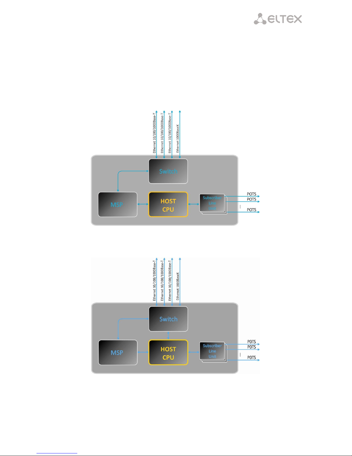
2.3 Product Design and Operating Principle
Subscriber voice signals are served to audio codecs of subscriber units, where they are encoded using one of
the selected standards, and then sent as digital packets to the controller via internal backbone. In addition to voice
signals, digital packets contain control and interaction signals.
Controller supports H.323 and SIP protocols and exchanging data between audio codecs and IP network via
MII interface and Ethernet switch.
Figure 3a shows TAU-72.IP functional diagram.
Figure 3a - TAU-72.IP functional diagram
Figure 3b shows TAU-36.IP functional diagram.
Figure 3b - TAU-36.IP functional diagram
Page 18

_________________________________________________________________________________
_________________________________________________________________________________
18 Universal Network Terminal TAU-72.IP/TAU-36.IP
2.4 Main Specifications
Main specifications of the terminal are listed in following tables:
Table 1 - Main specifications of the terminal
Protocols and Standarts
Protocol stack
H.323 v3/v4/v5
Communication protocol for session initiation, monitoring
and cancellation
SIP, SIP-T
Fax support
T.38 UDP Real-Time Fax
pass- through (G.711A/U)
Modem support
V.152
CISCO NSE
Voice standards
VAD (voice activity detector)
AEC (echo cancellation, G.168 recommendation)
CNG (comfort noise generator)
Voice codecs
Codecs
G.729, annex A, annex B
G.711(PCMA, PCMU)
G.723.1 (6.3 Kbps, 5.3 Kbps, Annex A)
G.726-32 (for SIP only)
Number of simultaneous channels, supported by device depending on codec type
Codec
Number of channels
G.711 (A/U)
G.729 / 20-80
G.729 A / 10
G.723.1
G.726
Т.38
TAU-72.IP
TAU-36.IP
72
72
62
58
72
54
36
36
36
36
36
36
Parameters of electrical Ethernet interface
No. of ports
3
Electrical connector
RJ-45
Transfer rate, Mbps
Autonegotiation, 10/100/1000 Mbps
duplex
Standards support
10/100/1000BaseT
Parameters of optical Ethernet interface
No. of ports
V1.0, V2.0
V3.0, V4.0, rev.B
1
2
Optical connector
Mini-Gbic (SFP):
1) full-duplex, two-fiber with 1310 nm (Single-Mode),
1000BaseX (LC connector), the supply voltage - 3.3V
2) duplex, single fiber with wavelengths in the
transmission/reception 1310/1550 nm, 1000BaseX (SC
connector), the supply voltage - 3.3V
Transfer rate, Mbps
1000 Mbps
duplex
Standards support
1000BaseX
Analogue user port specifications
Number of ports
TAU-72.IP
72
TAU-36.IP
36
Loop resistance
Up to 3.4 kΩ
Dialling reception
Pulse/frequency (DTMF)
Caller ID
FSK (ITU-T V.23, Bell 202), DTMF, ‘Russian Caller ID’
Page 19

________________________________________________________________________________
_________________________________________________________________________________
Universal Network Terminal TAU-72.IP/TAU-36.IP 19
Comprehensive protective circuit
Comprehensive protective circuit (current and voltage).
To protect subscriber line surge linear side
cross must be equipped with a three-pole
arresters voltage 230V operation.
Recommended arresters company KRONE 'МК, 230 V'
with heat protection spring.
Remote measurement of parameters of the subscriber line
yes
Parameters set
programmable
Console parameters
RS-232 serial port
Data rate, bps
115200
Electrical parameters of signals
According to ITU-T Recommendation V.28
Network and Configuration
Connection types
Static IP, DHCP client
Management
WEB, RS-232 console, Telnet, SSH
Security
User name and password verification, HTTPS, FTPS
Physical specifications and ambient conditions
Power voltage
V1.0, V2.0, V3.0
V4.0
rev.B
DC: -36..- 60V
DC: -36..- 60V
DC: -36..-72V
AC: ~150-250V 50 Hz
When using small
unventilated cabinet
(hallway installation)
permissible payload is 0.4
Erl./port.
If you use mechanical ventilation
of the cabinet, it is possible to
operate at
heavy load.
Power consumption without active subscribers
30 W
Current consumption of active subscriber set
30 mA
Operating temperature range
From 0 to 40°C
Relative humidity
Up to 80%
Ambient noise
Launch and operational mode: 0 dB
After processor heating: 50 dB
Dimensions (W x H x D)
420х45х240 mm, 19' form-factor, 1U size
Weight
3.2 kg
Page 20

_________________________________________________________________________________
_________________________________________________________________________________
20 Universal Network Terminal TAU-72.IP/TAU-36.IP
2.5 Design
TAU-72.IP/TAU-36.IP network terminal has a metal 420x45x240 case.
Front panel appearance is shown on Fig. 4a-d.
Fig. 4a - TAU-72.IP v2.0 front panel appearance
Fig. 4b - TAU-72.IP v3.0 front panel appearance
Fig. 4c - TAU-72.IP v4.0 and rev.B with DC power supply front panel appearance
Fig. 4d - TAU-72.IP v4.0 and rev.B with AC power supply front panel appearance
TAU-36.IP front panel appearance is shown on Fig. 4e-f.
Fig. 4e - TAU-36.IP with DC power supply front panel appearance
1 2 3 5 4 5 5 5 6 7 8 1 2 3 5 4 5 5 5 6 7 8 1 2 3 5 4 5 5 5 6 7 8
2a 3 5 4 5 5 5 6 7 8 1 2 3 4 5 5 6 7 8
Page 21

________________________________________________________________________________
_________________________________________________________________________________
Universal Network Terminal TAU-72.IP/TAU-36.IP 21
Fig. 4f - TAU-36.IP with AC power supply front panel appearance
Connectors, LEDs and controls located on the front panel of the device are listed in Table .
Table 2 – Description of connectors, LEDs, and controls located on the front panel
№
Front panel elements
Description
1
Power
Power toggle
2
-48V
Connector for DC power supply with rated voltage 48VDC
2a
~150 – 250 VAC, 50 Hz max 2A
Connector for AC power supply with voltage 150–250VAC, 50Hz
3 F Function button
4
Power
Power supply indicator
Status
Device operation indicator
Alarm
Alarm indicator
SFP (SFP0, SFP1)
Optical interface SFP processing indicator. Lights green when optic
link is present
5
Line 1...18, 19…36, 37…54, 55…72
4 CENC-36M connectors for analogue phones connection (pin
designation is listed in appendix A)
6
10/100/1000
3 x RJ-45 ports of Ethernet 10/100/1000 Base-T interfaces
7
COM
RS-232 console port for local control of the device
8
SFP (SFP0, SFP1)
Chassis for optical SFP modules of 1000Base-X Gigabit uplink
interface used for IP network connection
The layout of the device rear panel is shown on Fig. 5.
Fig. 5 - TAU-72.IP/TAU-36.IP rear panel appearance.
Grounding point is located on the rear panel of the device.
Connector pin designation is kisted in appendix A.
2a
3 4 5 5 6 7 8
Page 22

_________________________________________________________________________________
_________________________________________________________________________________
22 Universal Network Terminal TAU-72.IP/TAU-36.IP
2.6 Device ventilation
Fig. 6 - Fan location
There are ventilation openings on the device side panels that serve to remove heat. There are two fans on the
inside of the side panel (highlighted on Fig. above).
The air flow enters through the perforated right side panel of the device, passes through the entire range of
internal components, cooling each of them, and is brought out with left perforated panel fans. The remaining panels
of the device do not contain ventilation holes, which will allow to maintain the necessary internal pressure of air
flow.
Do not block any ventilation openings. This can lead to overheating of the device components and
cause its operation disturbances.
If the device is being installed into a closed non-ventilated cabinet with volume less than 180l per
device supplied by the DC, device performance will not exceed 0.8 Erlang per subscriber unit.
If the device is being installed into a closed non-ventilated cabinet with volume less than 180l per
device supplied by the AC, device performance will not exceed 0.4 Erlang per subscriber unit.
Page 23

________________________________________________________________________________
_________________________________________________________________________________
Universal Network Terminal TAU-72.IP/TAU-36.IP 23
2.7 Light indication
Power, 1Alarm, Status, SFP LEDs located on the front panel indicate the current state of the device. Table lists
possible states of the LEDs.
Table 3 - Device status LED indication
Indicator
Indicator State
Device state
Power2
solid green
Device power supply is on
off
Device power supply is off
Status
solid red
Operating system is not loaded (together with LED
Alarm)
Main application is not running (together with
LED Alarm, flashing in Fatal mode)
solid yellow
Device initialization in progress, subscriber ports are not
initialized yet
Address is not obtained through DHCP (if dynamic address
obtaining method is enabled)
solid green
Subscriber ports are initialized, device is in operation
off
Operating system loaded, board type identified
flashes red, yellow, and
green
Factory Safemode (together with
LED Alarm, flashing in Fatal mode),
or
factory reset (together with constantly solid Alarm LED)
Alarm
solid red
Alarm – port blocking, the output value of the parameter
sensor platform within range.
solid on
Warning – port blocking, operating system loading
flashes slowly
(once per second)
Error (failure) – module sensor failure (SFP module
installed, but there is no link)
flashes rapidly
(once per 200ms)
Fatal (critical failure) – connection of the main application
to subscriber ports is lost
off
Normal state
SFP (SFP0, SFP1)
solid green
Optical link is present
off
No optical link
Ethernet interface state is shown by 1000/100 socket built-in LED indicators.
Table 4 - Light indication of Ethernet 10/100/1000 interfaces
Yellow LED
10/100/1000
Green LED
10/100/1000
LED/Status
solid on
solid on
Port operates in 1000Base-T mode, data transfer is inactive
solid on
flashes
Port operates in 1000Base-T mode, data transfer is active
off
solid on
Port operates in 10/100Base-TX, data transfer is inactive
off
flashes
Port operates in 10/100Base-TX, data transfer is active
1
For TAU-72.IP/TAU-36.IP v1.0, v 2.0 only
Page 24

_________________________________________________________________________________
_________________________________________________________________________________
24 Universal Network Terminal TAU-72.IP/TAU-36.IP
2.8 'F' Function Button Operation
To reboot the operating device, press and hold 'F' button located on the front panel of the device for 1 to 9
seconds. When releasing the button, the Alarm LED will become solid red and the device will reboot. Also, this
button allows you to reset the device to factory settings to get access to the device when the IP address or the
password is forgotten or is not known. To do this, press and hold the 'F' button for 10-14 seconds until the Status
LED begins to flash yellow, green and red alternatively. Then the Alarm LED becomes solid red and the button
should be released. The configuration will be reset to factory settings and the device will be rebooted. After that,
you can access the device by IP address 192.168.1.2. When connecting with Web configurator, the default password
for admin user is rootpasswd. Further, you can view/change IP address and set a new password. If the button is not
released during the period between 10 and 14 seconds, after a while all LEDs will go out (the device will start
rebooting). Soon after the Status LED will begin to flash yellow, green and red alternatively, and the Alarm LED will
begin to flash red. When releasing the 'F' button at this moment, the configuration will not be reset to factory
settings and will switch to the Safemode. This mode allows changing the factory configuration, in other words,
selecting a method of network settings obtaining - statically or dynamically. If you continue to hold the ‘F’ button in
the Safemode, the cycle of the button operation will be repeated, that is, the restart will occur again if the button is
held for 1 to 9 seconds, the reset to the factory settings if the button is held for 10 to 14 seconds, etc.
For detailed description of the factory reset procedure, see Section 6.5 Reset the device to the factory
settings.
2.9 Delivery Package
2.9.1 TAU-72.IP delivery package
TAU-72.IP standard delivery package includes:
– Universal Network Terminal TAU-72.IP;
– CENC-36M connector - 4 pcs. (if there is no UTP CAT5E 18 cable in the order);
– RS-232 DB9(F) - DB9(F) connection cable;
– Earthing cable;
– A mounting set for 19’ rack;
– Operation manual on CD-disk;
– Declaration of conformity;
– Passport.
For DC power supply devices:
– PVA 2x1.5 power cord - 2 m.
For AC power supply devices:
– Power supply cord, europlug-eurosocket;
If ordered, delivery package may also include:
– 1000Base-T/Mini-Gbic (SFP) optical interface – 1/2pcs.
– UTP CAT5E 18 cable with CENC-36M connectors - 2 pcs.
2.9.2 TAU-36.IP delivery package
TAU-36.IP standard delivery package includes:
– Universal Network Terminal TAU-36.IP;
– CENC-36M connector - 2 pcs. (if there is no UTP CAT5E 18 cable in the order);
– RS-232 DB9(F) - DB9(F) connection cable;
Page 25

________________________________________________________________________________
_________________________________________________________________________________
Universal Network Terminal TAU-72.IP/TAU-36.IP 25
– Earthing cable;
– A mounting set for 19’ rack;
– Operation manual on CD-disk;
– Declaration of conformity;
– Passport.
For DC power supply devices:
– PVA 2x1.5 power cord - 2 m.
For AC power supply devices:
– Power supply cord, europlug-eurosocket;
If ordered, delivery package may also include:
– 1000Base-T/Mini-Gbic (SFP) optical interface – 1/2pcs.
– UTP CAT5E 18 cable with CENC-36M connectors - 1 pcs.
Page 26

_________________________________________________________________________________
_________________________________________________________________________________
26 Universal Network Terminal TAU-72.IP/TAU-36.IP
3 INSTALLATION ORDER AND SAFETY MEASURES
This section describes safety measures and installation of the equipment into a rack and connection to a
power supply.
Check the device for visible mechanical damage before installing and turning it on. In case of any damage, stop
the installation, fill in a corresponding document and contact your supplier.
3.1 Safety instruction
3.1.1 General Guidelines
Any operations with the equipment should comply to the Safety Rules for Operation of Customers' Electrical
Installations.
Operations with the equipment should be carried out only by personnel authorised in accordance with
the safety requirements.
1. Before operating the device, all engineers should undergo special training.
2. TAU-72.IP/TAU-36.IP terminal could be permanently used provided the following requirements are met:
– Ambient temperature from 0 to +40°C.
– Relative humidity up to 80% at +25°C.
– Atmosphere pressure from 6,0х10*4 to 10,7х10*4 Pa (from 450 to 800 mm Hg).
3. The device should be not be exposed to mechanical shock, vibration, smoke, dust, water, and chemicals.
4. To avoid components overheating which may result in device malfunction, do not block air vents or place
objects on the equipment.
3.1.2 Electrical Safety Requirements
1. Prior to connecting the device to a power source, ensure that the equipment case is grounded with an
earth bonding point. The earthing wire should be securely connected to the earth bonding point. The
resistance between the earth bonding point and earthing busbar should be less than 0,1 Ω.
2. PC and measurement instruments should be grounded prior to connection to the device. The potential
difference between the equipment case and the cases of the instruments should be less than 1V.
3. Make sure the device is off, when installing or removing the case.
Page 27

________________________________________________________________________________
_________________________________________________________________________________
Universal Network Terminal TAU-72.IP/TAU-36.IP 27
3.1.3 Electrostatic Discharge Safety Measures
For the avoidance of failures caused by electrostatic discharge, we strongly recommend to:
1. Put on esd belt, shoes or wrist strap to prevent electrostatic charge accumulation (for the wrist strap,
ensure that it fits snugly to the skin) and to ground the cable before starting to work with the equipment.
3.2 TAU-72.IP/TAU-36.IP Installation
1. If the device was exposed to low temperatures for a long time before installation, leave it for 2 hours at
ambient temperature prior to operation. If the device was exposed to high humidity for a long time, leave
it for at least 12 hours in normal conditions prior to turning it on.
2. Mount the device. The device is intended to be installed into 19’ rack using the mounting set or mounted
on the horizontally oriented perforated shelf.
If the device is being installed into a closed non-ventilated cabinet with volume less than 180l per device,
device performance will not exceed 0.8 Erlang per subscriber unit.
3. Ground the case of the device after installation. This should be done prior to connecting the device to the
power supply. An insulated multiconductor wire should be used for earthing. The device grounding and the
earthing wire section should comply with Electric Installation Code. The earth bonding point is located at
the right bottom corner of the rear panel, see Fig. 5.
3.2.1 Opening the case
First power TAU-72.IP/TAU-36.IP off, disconnect all cables.
Fig. 7 - TAU-72.IP/TAU-36.IP case opening order
1. Detach brackets from device case using screwdriver.
2. Detach device front and top panel fixation screws, using screwdriver, as shown on Fig. 7.
3. Remove device top panel by pulling it up.
Page 28

_________________________________________________________________________________
_________________________________________________________________________________
28 Universal Network Terminal TAU-72.IP/TAU-36.IP
Execute actions that listed above in reverse order to assemble the device into case.
Fig. 8 - TAU-72.IP/TAU-36.IP assembling screw types
Fig. above shows screw types, used for assembling the device into case:
1. Rack brackets mounting.
2. Case parts mounting.
3. Board, ventilation unit, plug, rail mountings.
4. Fan mounting screw.
5. Earthing screw.
Don't use inappropriate screw type when assembling the device. Screw type changing may cause
device failure.
3.3 Startup sequence
Connect subscriber lines, optical and electrical Ethernet cables to corresponding switch connectors.
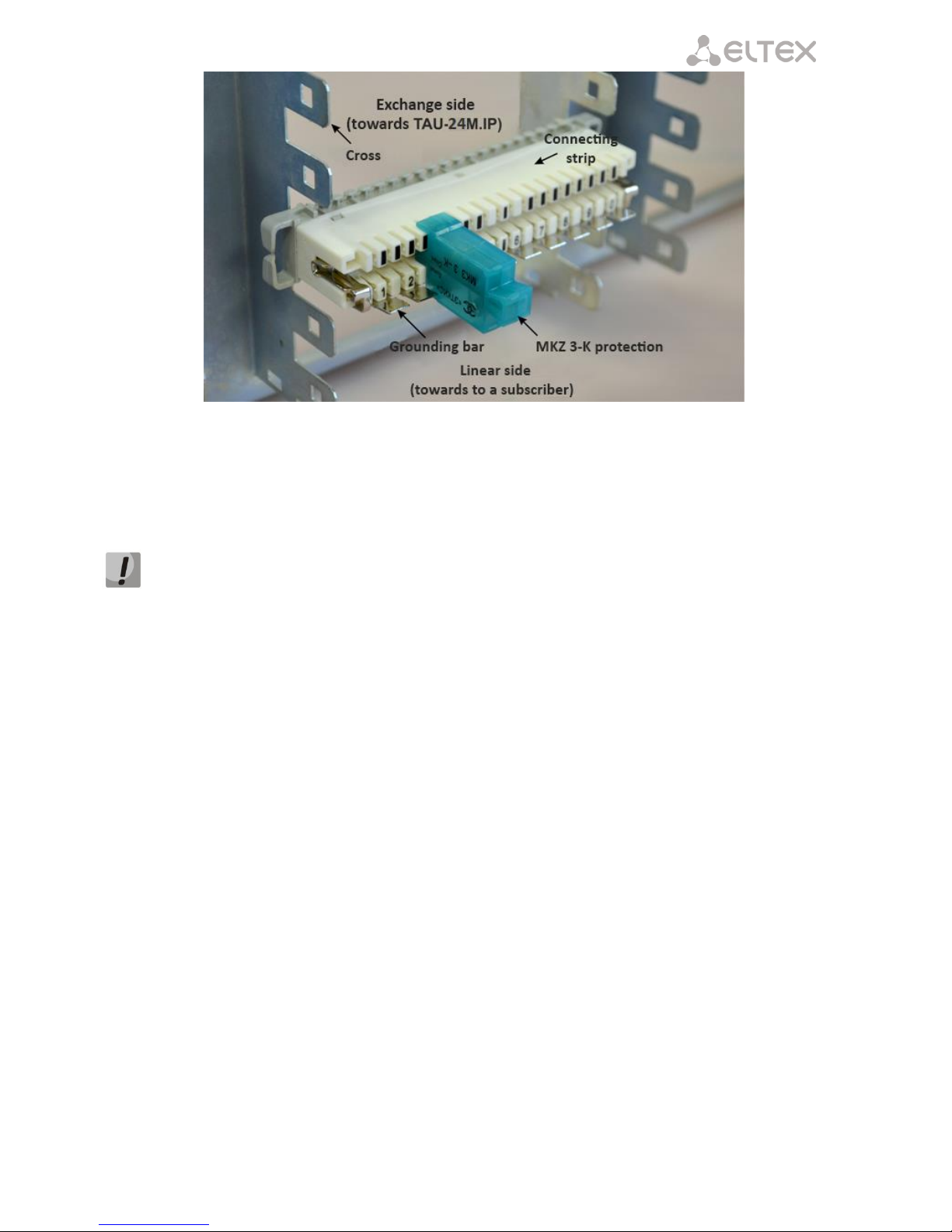
To protect subscriber lines against surge, linear side of the cross must be equipped with ‘MKZ
3-K’ arresters with operate voltage of 230V.
The arresters (MKZ) are designed to protect the FXS and FXO sets of TAU-72M.IP and TAU36M.IP gateways from dangerous surge voltages and currents in air cable strands caused by
lightning discharge, high-voltage electric transmission lines, overhead wirings of electric railway and
various industrial sources of impulse interferences as well as from contact with low voltage power
lines.
The arresters contain two voltage protection cascades (the first one is on the aerial fuse, the
second one is on the semiconductor switches) and current protection (on the polymer posistors).
The installation of MKZ arrestors requires the grounding bar mounted on the linear side. The
arrester is installed in normally closed connecting strip (Krone, Intercross or their compatibles)
according to the marking on the device body. The connection diagram is shown in Fig. 9.
Page 29
________________________________________________________________________________
_________________________________________________________________________________
Universal Network Terminal TAU-72.IP/TAU-36.IP 29
Fig. 9 - Connection diagram
Connect the power supply cable to the device. Depending on the provided sources, the device could be
powered from grounded power outlet 220/110VAC, 50/60Hz, or from -48...-60VDC power supply. To connect the
device to 220VAC electrical network, use the cable provided with the delivery package. To connect the device to DC
power supply, use the cable with cross-section not less than 1mm2.
When connecting to the 220V AC mains it is necessary to mount devices for electrical overshoot
protection.
Ensure that all cables are undamaged and securely connected.
Turn the device on and check the front panel LEDs to make sure the terminal is in normal operating conditions
(Section 2.7 Light indication).
Page 30

_________________________________________________________________________________
_________________________________________________________________________________
30 Universal Network Terminal TAU-72.IP/TAU-36.IP
4 GENERAL SWITCH OPERATION GUIDELINES
A web interface is one of the easiest and most convenient ways to configure and monitor the device.
In order to prevent an unauthorized access to the device, we recommend to change administrator, operator
and non-privileged user passwords to access the device. For setting password for access via Web interface, see
Section 5.1.6.6. We recommend to write down and store defined passwords in a safe place, inaccessible by
intruders.
In order to prevent device configuration data loss, e.g. after reset to factory settings, we recommend making
configuration backup copies and storing them on a PC each time significant changes are made.
Page 31

________________________________________________________________________________
_________________________________________________________________________________
Universal Network Terminal TAU-72.IP/TAU-36.IP 31
5 DEVICE CONFIGURATION
You can connect to the device using four methods: via web interface, via telnet/ssh2 protocols, or via serial
port (console parameters: 115200, 8, n, 1, n).
The device runs on Linux, settings are stored as text files in a directory /etc ~/config (in normal mode /etc ~ is
a link to the directory /etc, when booting from pressing 'F' in directory /etc ~ configured by the user, and in the /etc
directory factory configuration of the device).
Configuration files can be edited by connecting the device via the RS-232 or telnet using built-in text editor
joe.
To save the contents of the directory / etc ~ non-volatile memory device, you must execute the save
command. The changes take effect after rebooting the device.
5.1 TAU-72.IP/TAU-36.IP configuration via WEB Interface. Administrator Access
1
To configure the device, establish connection in the web browser, e.g. Firefox, Internet Explorer.
TAU-72.IP/TAU-36.IP factory default IP address – 192.168.1.2, network mask–255.255.255.0
After entering IP address the device will request username and password.
Initial startup username: admin, password: rootpasswd.
Up to 4 users may connect to the device Web interface simultaneously.
The following menu will appear on the administrator's terminal: To prevent unauthorized access to device in
the future, it is recommended to change password (see Section 5.1.6.6).
1
The description is an example of the configurator for TAU-72.IP. For TAU-16.IP device settings are the same, the number of
configurable ports - 36.
For security reasons, duration of authorized access session is limited for 20 minutes, i.e. if you are
inactive after establishing connection to the device interface for the stated amount of time, the
gateway will be forced to end the session. This restriction is not effective in cases when you leave
'Monitoring' or 'System info' pages open, as these pages perform periodic polling of the device
data.
In all tabs, the Save button stores configuration into the non-volatile (flash) memory of the
device.
Page 32

_________________________________________________________________________________
_________________________________________________________________________________
32 Universal Network Terminal TAU-72.IP/TAU-36.IP
Web Configurator Language
Web configurator allows you to select from two interface languages: 'Russian (Ru)' and 'English (En)'.
Firmware version default language is English. To change the interface language, select the respective link in
the web configurator header bar (on the right side).
Example of web configurator menu in Russian:
Example of web configurator menu in English:
Indication of Changes in Web Configurator
Web configurator supports indication of configuration changes that is shown in the header bar of
configuration interface (TAU-72.IP/TAU-36.IP WEB configurator). Table lists indicator states ('*' character in the
header bar of configuration interface).
Table 5 - Indicator state *
Indicator State
Description
* character is red
Changes has been made to the configuration, but it has not been saved to flash
memory yet.
* character is not shown
No changes has been made to the configuration or changes has been successfully
saved to flash memory;
Page 33

________________________________________________________________________________
_________________________________________________________________________________
Universal Network Terminal TAU-72.IP/TAU-36.IP 33
Table lists description of configuration menu windows.
Table 6 – Description of configuration menu, administrator access
Menu (en)
Menu (ru)
Description
Network settings
Сетевые настройки
Adjustment of the device network settings
Network
Сеть
Configuration of network settings
IPSec
IPSec
Configuration of IPSec settings
VLAN conf
VLAN
VLAN configuration
Route
Таблица маршрутизации
Static route configuration for WAN and VLAN
interfaces
Hosts
DNS хосты
Local DNS server configuration
SNMP
SNMP
SNMP agent configuration
Syslog
Журнал
Syslog server configuration
MAC filter
Фильтр МАС
Configuration of filtration by MAC addresses
Firewall
Брандмауэр
Configuration of denied/allowed IP server addresses
NTP
NTP
NTP configuration
ACS
ACS
TR-069 monitoring and management protocol
settings
Autoupdate
Автообновление
Automatic update configuration
PBX
PBX
VoIP (Voice over IP) configuration
Main
Основные функции
Device basic settings
SIP/H323 Profiles
Профили SIP/H323
Configuration of SIP/H323 profiles
SIP Common
SIP Общие
SIP common settings
H323
H323
Н323 protocol settings (works in profile 1 only)
Profile 1..8
Профиль 1..8
Configuration of profiles
SIP Custom
SIP настройки профиля
SIP custom settings for a profile
Codecs
Кодеки
Codec settings for a profile
Dialplan
План набора
Routing settings for a profile
Alert info
Alert info
Configuration of a distinctive ring, formed by Alert
Info value
TCP/IP
TCP/IP
Configuration of network port range for various
protocols
Ports
Абонентские порты
Configuration of device subscriber ports and
subscriber profiles
Call limits
Ограничение вызовов
Configuration of simultaneous call limits
Suppl. Service Codes
Услуги ДВО
Configuration of supplementary service codes
Serial groups
Группы вызова
Configuration of serial groups
PickUp groups
Группы перехвата
Configuration of pickup groups
Distinctive ring
Звонок особого типа
'Distinctive ring' service administration
Modifiers
Модификаторы
Configuration of number modifiers
Acoustic signals
Акустические сигналы
Configuration of acoustic signals parameters
Dialplan profiles
Профили плана нумерации
Configuration of profiles for routing
Profile 1..4
Профиль 1..4
Configuration of profiles
Switch
Коммутатор
Configuration of switch settings
Switch ports settings
Настройки портов
коммутатора
Configuration of integrated Ethernet switch ports
802.1q
802.1q
Configuration of packet routing rules for switch
operation in 802.1q mode
QoS & Bandwidth control
QoS и управление полосой
пропускания
Quality of service functions and bandwidth limits
configuration
Monitoring
Мониторинг
Device monitoring
When network settings are changed, web service on the device restarts, and when the connection
is established using new address, '*' character will not be shown, but the configuration will still
contain changes that are not saved to the flash memory.
Page 34

_________________________________________________________________________________
_________________________________________________________________________________
34 Universal Network Terminal TAU-72.IP/TAU-36.IP
Port
Порт
Device subscriber ports status information
Status
Статус
Gateway hardware platform status information–
voltages, temperature sensors, fans, SFP data
Switch
Коммутатор
Switch port status monitoring
Suppl. Service
ДВО
Information on the current status of supplementary
services on subscriber port
IMS SS status
Статус услуг IMS
Monitoring of services, software controlled switch
with support for IMS
Serial groups
Группы вызова
Monitoring of registration serial groups
IMS SS status
Статус услуг IMS
Information about current IMS services status
Serial groups
Группы вызова
Information about current serial groups status
System info
Информация о системе
System info
Device info
Информация об
устройстве
View the device and network settings information
Route
Таблица маршрутизации
View the Routing table
ARP
ARP
View the ARP table
Service
Сервисные функции
Firmware update, configuration file operations,
rebooting device, setting/changing passwords
Firmware upgrade
Обновление ПО
Subscriber units firmware update
Backup/Restore
Управление конфигурацией
Download/upload configuration files to/from PC
Reboot
Перезагрузка
Rebooting device
Security
Безопасность
Encryption feature
MOH
Музыка
Download/upload audio file for call hold service
Password
Пароли
Management of passwords used to access the device
via Web interface
Call history
Журнал вызовов
View and upload of call log
Logout
Выход
Finish the device administration session for the
current user
Page 35

________________________________________________________________________________
_________________________________________________________________________________
Universal Network Terminal TAU-72.IP/TAU-36.IP 35
5.1.1 The ‘Network settings’ menu
In the Network settings menu, you can define network settings of the device.
5.1.1.1 The ‘Network’ submenu
In the 'Network' submenu, you may specify the device name, IP address, subnet mask, network broadcast
address, DNS server address, device access rules, etc.
DHCP is a protocol that allows to automatically obtain IP address and other settings required for operation in
TCP/IP network. It allows the gateway to obtain all necessary network settings from DHCP server.
SNMP is a simple network management protocol. It allows the gateway to send real-time messages on
occurred failures to controlling SNMP manager. Also allows the gateway to send real-time messages on occurred
failures to controlling SNMP manager. Also, gateway SNMP agent supports monitoring of gateway sensors' status on
request from SNMP manager.
DNS is a protocol that allows to obtain domain information. It allows the gateway to obtain IP address of the
communicating device by its network name (hostname). It may be necessary, e.g. when specifying hosts in the
routing plan or using network name of the SIP server as its address.
TELNET is a protocol that allows to establish mechanisms of control over the network. It allows you to
remotely connect to the gateway from a computer for configuration and management purposes. For TELNET
protocol operation, the data transfer process is not encrypted.
SSH is a protocol that allows to establish remote control over the network. Serves the similar purpose as
TELNET protocol, but unlike the latter provides encryption of the transferred data.
LLDP (Link Layer Discovery Protocol) is a data-link level protocol that allows network equipment to notify the
neighbouring devices located in a local network on their capabilities and gather such notifications from the
neighbouring devices.
STP (Spanning Tree Protocol) is a network protocol that allows to eliminate loops in the arbitrary Ethernet
network topology, containing one or multiple network bridges connected with redundant links.
TR-069 is a technical specification that defines the Internet protocol for management of network equipment –
CWMP (CPE WAN Management Protocol). The protocol allows for comprehensive device configuration, software
updates, reading device information (software version, model, serial number, etc.), complete configuration file
downloading/uploading, remote device restart (TR-069, TR-098, TR-104 specifications are supported).
STUN - network protocol that allows subscriber behind the NAT to define external IP-address.
You do not have to reboot the gateway in order to apply network settings. When applying
settings, all current calls will be terminated!
Page 36

_________________________________________________________________________________
_________________________________________________________________________________
36 Universal Network Terminal TAU-72.IP/TAU-36.IP
When selecting 'Static' option in the 'Protocol' field, the following parameters are available:
Network settings:
– Protocol – selection of static or dynamic (DHCP) protocol to assign network settings.
Dynamic assignment of network settings:
To obtain network settings use DHCP.
Supported options:
1 – network mask;
3 – default network gateway address;
Page 37

________________________________________________________________________________
_________________________________________________________________________________
Universal Network Terminal TAU-72.IP/TAU-36.IP 37
56 – DNS server address;
12 – device network name;
15–domain name;
28 – network broadcast address;
42 – NTP server address;
43–specific vendor information (for option usage, see subsection 'TR-069 Monitoring and Management
Protocol Settings' below);
60–specific vendor information (for option usage, see subsection 'DHCP Options' below);
66–TFTP server address (for option usage, see subsection 'Autoupdate Settings' below);
67–name of the file with firmware versions and configurations (for option usage, see subsection
'Autoupdate Settings' below);
82–agent informational parameter (Agent Circuit ID and Agent Remote ID suboptions);
120–outbound SIP servers (for option usage, see Section 5.1.2.2.3SIP Custom Parameters (Profile n/SIP
Custom));
121–classless static routes (for option usage, see Section 5.1.1.4The 'Route' submenu).
– Get GW via DHCP – when checked, use default gateway obtained via DHCP;
– Default gateway – default address of a network gateway. I.e. the address of a gateway that receives all the
traffic falling outside the scope of every static routing rule;
– Primary DNS IP – primary DNS server address. To use a local DNS, enter IP address 127.0.0.1 into the field;
– Secondary DNS IP – secondary DNS server address;
– MTU – maximum size of the packet that can be transmitted via WAN interface without fragmentation.
Static assignment of network settings:
– IP address – the device IP address;
– Netmask – the device network mask;
– Broadcast – the device subnet broadcast address;
– Default gateway – default address of a network gateway. I.e. the address of a gateway that receives all the
traffic falling outside the scope of every static routing rule;
– Primary DNS IP – primary DNS server address. To use a local DNS, enter IP address 127.0.0.1 into the field;
– Secondary DNS IP – secondary DNS server address;
– MTU – maximum size of the packet that can be transmitted via WAN interface without fragmentation.
DHCP Options:
– Alternative option 60 enable – when checked, use alternative Option 60 value, specified by user. Otherwise,
in Option 60 DHCP request the device will send specific vendor information in the following format:
[VENDOR: vendor][DEVICE: device type][HW: hardware version][SN: serial number][WAN: МАС
address][VERSION: firmware version]
where:
– Vendor–Eltex;
– Device type–depends on factory settings;
– Serial number–depends on factory settings;
Page 38

_________________________________________________________________________________
_________________________________________________________________________________
38 Universal Network Terminal TAU-72.IP/TAU-36.IP
– МАС address–depends on factory settings.
You may check factory settings and firmware version in 'System info' tab (Section 5.3.2The 'System
info' menu) of the web interface.
Example:
[VENDOR:Eltex][DEVICE:TAU72][HW:0x21][SN:MS5370043][WAN:00:01:09:44:33:22][VERSION:2.10.0]
– Alternative option 60 value – alternative Option 60 value (format: string), specified by user;
– Option 82. Agent circuit identifier (Option 82. Agent Circuit ID – allows to add Option 82, Suboption 1 – Agent
Circuit ID, into DHCP request;
– Option 82. Remote agent identifier (Option 82. Agent Remote ID – allows to add Option 82, Suboption 2 –
Agent Remote ID, into DHCP request.
Services:
– Enable TELNET – when checked, enable device access via Telnet protocol, otherwise it is disabled;
– TELNET port – TCP port (23 by default) for Telnet protocol operation;
– Enable SSH – when checked, enable device access via SSH protocol, otherwise it is disabled;
– SSH port – TCP port (22 by default) for SSH protocol operation;
– Enable STP – when checked, STP is enabled;
– Enable WEB – when checked, enable device access via web interface, otherwise it is disabled;
– HTTP port – web server port (80 by default) for HTTP protocol operation;
– HTTPS port – web server port (443 by default) for HTTPS protocol operation.
VPN Settings:
– Protocol – selection of protocol to create a VPN.
Page 39

________________________________________________________________________________
_________________________________________________________________________________
Universal Network Terminal TAU-72.IP/TAU-36.IP 39
• Off – don't use VPN;
• PPPoE – use PPPoE for a tunnel creation;
• PPTP – use PPTP for a tunnel.
PPPoE Settings:
– Username – username for PPP server authentication;
– Password – password for PPP server authentication;
– Service name – service name requested when PPP connection establishing. Query must be replyed only by
PPPoE server, that supports this service;
– VLAN – when checked, use separate VLAN for PPPoE access;
– VLAN ID – VLAN identifier;
– MTU – maximum packet size that could be transferred through PPP interface without fragmentation;
– MRU – maximum packet size that could be received through PPP interface without fragmentation;
– LCP echo interval (s) – period of request transmission for LCP echo PPP connection control;
– LCP echo failure count – permissible amount of errors connected with LCP echo requests transmission. In
case this amount of LCP echo queries weren't answered, PPP connection will be terminated.
PPTP Settings:
– PPTP server – PPPT server IP address;
– Username – username for PPP server authentication;
– Password – password for PPP server authentication;
– VLAN – when checked, use separate VLAN for PPTP access;
– VLAN ID – VLAN identifier; MTU – maximum packet size that could be transferred through PPP interface
without fragmentation;
– MRU – maximum packet size that could be received through PPP interface without fragmentation;
– LCP echo interval (s) – period of request transmission for LCP echo PPP connection control;
– LCP echo failure count – permissible amount of errors connected with LCP echo requests transmission. In
case this amount of LCP echo queries weren't answered, PPP connection will be terminated.
If the network is managed through PPTP, do not click the Submit Changes button after you finish
PPTP connection configuration as it may lead to connection loss. Go to 'VLAN conf' tab first, set
the setting for 'signalling/control traffic transmission via РРTP', and then apply configuration
changes using the Submit Changes button.
If the network is managed through PPPoE, do not click the Submit Changes button after you finish
PPPoE connection configuration as it may lead to connection loss. Go to 'VLAN conf' tab first, set
the setting for 'RTP/signalling/control traffic transmission via РРРоЕ', and then apply
configuration changes using the Submit Changes button.
Page 40

_________________________________________________________________________________
_________________________________________________________________________________
40 Universal Network Terminal TAU-72.IP/TAU-36.IP
LLDP Settings:
– Enable LLDP – when checked, enable LLDP protocol;
– LLDP transmit period – LLDP message transmission period. Default value: 30 second.
To apply changes, click the Submit Changes button. To discard all changes made to configuration, click the
Undo All Changes button.
To store changes to non-volatile memory of the device, click the Save button.
5.1.1.2 The ‘IPSec settings’ submenu
In this submenu, you may configure IPSec encryption (IP Security). IPSec is a set of protocols to provide data
protection (data is transmitted via IP). IPSec allows you to provide authentication, integrity check and/or IP-packets
encryption. IPSec includes protocols for tamper-free key exchange in Internet.
IPSec settings:
– IPSec enable – when selected, permit to use IPSec protocol for data encryption;
– Local IP address – the device address for operation via IPSec protocol;
– Local subnet – local subnet address;
– Local netmask – local subnet mask;
– Local subnet in cooperation with Local netmask determine local subnet for creation of network-to-network
or network-to-point topologies;
– Remote subnet – remote subnet address;
Page 41

________________________________________________________________________________
_________________________________________________________________________________
Universal Network Terminal TAU-72.IP/TAU-36.IP 41
– Remote netmask – remote subnet mask;
Remote subnet in cooperation with Remote netmask determine address of remote subnet for
connection with using encryption via IPSec protocol. If mask has value 255.255.255.255 then connection is
established with a single host. Mask that differs from 255.255.255.255 allows defining a whole subnet. Thus,
functionality of the device allows you to organize the following 4 network topologies with using encryption
traffic via IPSec protocol: point-to-point, network-to-point, point-to-network, network-to-network;
– Remote gateway – gateway used for remote network access.
– NAT-T mode – NAT-T (NAT Traversal) encapsulates IPSec traffic and simultaneously creates UDP packets to
be sent correctly by a NAT device. For this purpose, NAT-T adds an additional UDP header before IPSec
packet so it would be processed as an ordinary UDP packet and the recipient host would not perform any
integrity checks. When the packet arrives to the destination, UDP header is removed and the packet goes
further as an encapsulated IPSec packet. With NAT-T technique, you may establish communication between
IPSec clients in secured networks and public IPSec hosts via firewalls. You can choose one of the three NAT-T
operation modes:
• on – NAT-T mode is activated only when NAT is detected on the way to the destination host;
• force – use NAT-T in any case;
• off – disable NAT-T on connection establishment.
The following NAT-T settings become available when choosing NAT-T On/Force mode:
▪ NAT-T UDP port– UDP port for packets used for IPSec message encapsulation. Default value is
4500;
▪ NAT-T keepalive packet transmission interval, sec – periodic message transmission interval for
UDP connection keepalive on the device performing NAT functions.
– Aggressive mode – phase 1 operation mode, when all the necessary data is exchanged using three
unencrypted packets. In the main mode, the exchange process involves six unencrypted packets.
– My identifier type – identifier type of the device: address, fqdn, user_fqdn, asn1dn;
– My identifier – device identifier used for identification during phase 1 (fill in, if required). Identifier format
depends on the type.
In Phase 1 and Phase 2 sections parameters and algorithms used in the first and the second steps of IPSec
connection are configured.
Phase 1
During the first step (phase), two hosts negotiate on the identification method, encryption algorithm, hash
algorithm and Diffie Hellman group. Also, they identify each other. For phase 1, there are the following settings:
– Pre-shared key;
– Authentication algorithm – select an authentication algorithm from the list: MD5, SHA1, SHA256, SHA384,
SHA512;
– Encryption algorithm – select an encryption algorithm from the list: DES, 3DES, Blowfish, Cast128, AES;
– Diffie Hellman group – select Diffie-Hellman group;
Page 42

_________________________________________________________________________________
_________________________________________________________________________________
42 Universal Network Terminal TAU-72.IP/TAU-36.IP
– Phase 1 lifetime, sec – time that should pass for hosts' mutual re-identification and policy comparison (other
name IKE SA lifetime). Default value is 24 hours (86400 seconds).
Phase 2
During the second step, key data is generated, hosts negotiate on the utilized policy. This mode—also called as
'quick mode'—differs from the phase 1 in that it may be established after the first step only, when all the phase 2
packets are encrypted.
– Authentication algorithm – select an authentication algorithm from the list: HMAC-MD5, HMAC-SHA1,
HMAC-SHA256, HMAC-SHA384, HMAC-SHA512;
– Encryption algorithm – select an encryption algorithm from the list: DES, 3DES, Blowfish, Twofish, Cast128,
AES;
– Diffie Hellman group – select Diffie-Hellman group;
– Phase 2 lifetime, sec – time that should pass for data encryption key changeover (other name IPSec SA
lifetime). Default value is 60 minutes (3600 seconds).
To apply changes, click the Submit Changes button. To discard all changes made to configuration, click the
Undo All Changes button. To store changes to non-volatile memory of the device, click the Save button.
Settings for 'signalling/control traffic via IPSec' transmission are performed in the 'VLAN conf' tab.
5.1.1.3 The 'VLAN conf' submenu. Virtual Local Area Network
In 'VLAN conf' submenu, you will be able to configure VLAN network settings and transmission of signals and
voice traffic, and also set up device management through various VLAN networks.
VLAN is a virtual local area network. VLAN consists of a group of hosts combined into a single network
regardless of their location. Devices grouped into a single VLAN will have the same VLAN ID.
Gateway software allows to set up device management (via web interface, TELNET, or SSH), transmission of
signals (SIP, H.323/RAS protocol data) and voice traffic (RTP) through a single or multiple virtual local area networks.
This feature may become useful, when a separate network is used for device management in organization.
You don't have to reboot the gateway in order to apply VLAN settings. When applying settings, all
current calls will be terminated!
IP addresses assigned to WAN interface as well as VLAN interfaces should belong to different
subnets. For example, if you use a mask 255.255.240.0, IP addresses 192.168.1.6 and
192.168.2.199 will belong to a single network, and if you use a mask 255.255.255.0, they will
belong to different networks.
Page 43

________________________________________________________________________________
_________________________________________________________________________________
Universal Network Terminal TAU-72.IP/TAU-36.IP 43
In sections VLAN1, VLAN2, VLAN3, you may configure from one to three VLAN networks:
– Enable – when checked, enable VLAN;
– VLAN ID – VLAN identifier (1-4095);
– DHCP for VLAN – when checked, VLAN network settings will be obtained via DHCP;
– Get GW via DHCP – when checked, use default gateway obtained via DHCP;
– IP address – VLAN interface IP address;
– VLAN netmask – network mask used for VLAN interface;
– VLAN broadcast – subnet broadcast address of VLAN interface;
– MTU – maximum packet size that could be transferred through PPP interface without fragmentation (86-
1500);
– Class of service (802.1p) – 802.1р priority for the current VLAN.
Traffic Type – VLAN Number
In section 'Traffic Type – VLAN Number', you can assign one of three configured VLANs (VLAN1, VLAN2,
VLAN3) or PPPoE interface to the specific traffic type:
Page 44

_________________________________________________________________________________
_________________________________________________________________________________
44 Universal Network Terminal TAU-72.IP/TAU-36.IP
− RTP – VLAN, PPPoE assignment for voice traffic;
− Signaling (SIP/H.323) – VLAN, PPPoE, PPTP, IPSec assignment for SIP/H323 signal traffic;
− Control (WEB/Telnet) – VLAN, PPPoE, PPTP, IPSec assignment for gateway management via web interface,
telnet, and SSH.
To apply changes, click the Submit Changes button. To discard all changes made to configuration, click the
Undo All Changes button.
5.1.1.4 The 'Route' submenu
In the 'Route' submenu' you can configure static routes for WAN and VLAN interfaces.
Static routing allows you to route packets to defined IP networks or IP addresses through the specified
gateways. Packets sent to IP addresses not belonging to the gateway IP network and falling outside the scope of
static routing rules will be sent to the default gateway.
– Network – destination IP network or address;
– Mask – network mask. If IP address is specified in the 'Network' field, use the following mask:
255.255.255.255;
– Gateway – address of a network gateway that will be used for packet routing to the defined network (or IP
address);
– VLAN – virtual local area network identifier (VLAN ID). Use it when destination IP network or IP address
belong to virtual local area network, otherwise leave this field blank.
To add/apply a new route, enter the data in the field with icon, and click the Submit Changes button. To
remove the route, select 'Delete' checkbox and click the Submit Changes button.
To discard all changes made to configuration, click the Undo All Changes button. To store changes to nonvolatile memory of the device, click the Save button.
Apart from configuration performed via web configurator, the gateway is able to receive static route
settings via Option 121 of DHCP protocol. Routes in this option are sent as a list of 'destination
description/gateway' pairs, the format is described in RFC 3442.
Voice traffic will be transmitted via PPPoE only after the device is restarted!
When selecting for all types: RTP, signalling and controlling PPPoE value won't have any IP
address, even if IP address for WAN will be setted up in configuration.
Page 45

________________________________________________________________________________
_________________________________________________________________________________
Universal Network Terminal TAU-72.IP/TAU-36.IP 45
5.1.1.5 The 'Hosts' submenu
In the 'Hosts' submenu, you can configure settings required for local DNS operation.
To enable local DNS, enter 127.0.0.1 into 'DNS' field in the 'Network' tab.
Local DNS—allows the gateway to obtain IP address of the communicating device by its domain name. You
may use Local DNS in cases when DNS server is missing from the network segment that the gateway belongs to, and
you need to establish routing using network names, or when you have to use SIP server network name as its
address. Although, you have to know matches between host names (domains) and their IP addresses. Also, local DNS
allows you to configure SIP domain on a gateway (see Section 5.1.2.2.3SIP Custom Parameters (Profile n/SIP
Custom)).
Local DNS configuration involves definition of matches between hostnames and their respective IP addresses.
To enable local DNS, enter 127.0.0.1 into 'Primary DNS IP' field in the 'Network' tab. Also, local DNS will be
used when configured DNS servers are not available.
Table of domain names (DNS hosts):
– Name – name of a host;
– IP-address – IP address of a host.
To add/apply a new route, enter the data in the field with icon, and click the Submit Changes button. To
remove the route, select 'Delete' checkbox and click the Submit Changes button.
After implementation of changes, click the Submit Changes button; to discard all changes, click the Undo All
Changes button; to save changes, click the Save button.
Page 46

_________________________________________________________________________________
_________________________________________________________________________________
46 Universal Network Terminal TAU-72.IP/TAU-36.IP
5.1.1.6 The 'SNMP' submenu
TAU-72.IP/TAU-36.IP software allows to monitor status of the device and its sensors and also configuring
certain parameters of the device via SNMP protocol. In 'SNMP' submenu, you can configure settings of SNMP agent.
Device supports SNMPv1, SNMPv2c, SNMPv3 protocol versions.
For detailed monitoring parameters and Traps description, see MIBs on disk shipped with the
gateway.
After implementation of changes, click the Submit Changes button; to discard all changes, click the Undo All
Changes button; to save changes, click the Save button.
SNMP configuration:
– Trap Sink – IP address of a trap recipient (manager server or proxy agent server);
– Trap Type – SNMP trap type (SNMP-trap or SNMPv2-trap);
– SysName – device system name;
– SysContact – device vendor contact information;
– SysLocation – device location;
– roCommunity – password for parameter reading (common: public);
– rwCommunity – password for parameter writing (common: private);
– trapCommunity – password located in traps.
SNMP v3 configuration:
The system employs a single SNMPv3 user that executes SORM commands. SORM feature implementation is
based on rfc3924 recommendation–Cisco Architecture for Lawful Intercept in IP Networks. To perform the pickup,
the following MIBs are used: CISCO-IP-TAP-MIB.my and CISCO-TAP2-MIB.my.
– User name – account username;
Page 47

________________________________________________________________________________
_________________________________________________________________________________
Universal Network Terminal TAU-72.IP/TAU-36.IP 47
– User password – access password. The password should contain 8 characters or more;
– View type – account access mode selection:
• Read/Write – read/write mode;
• Read only – read-only mode;
– Delete – click this button to delete all accounts for access via SNMP v3.
Click the Configure button to apply SNMPv3 user configuration. Settings will be applied immediately. Click the
Delete button to delete the record.
To discard all changes made to configuration, click the Undo All Changes button. To set the default
parameters, click the Defaults button. To apply changes, click the Submit Changes button.
MIB Tree
SNMP TRAP
SNMP agent sends a message (SNMP-trap or SNMPv2-trap), when the following events occur:
– Port is blocked;
– Port is unblocked;
– Unit power supply voltage is changed;
– Fans turned on/off;
– Fans malfunction;
– SFP module is installed, but there is no optical link;
– BPU connection lost/resumed;
Page 48

_________________________________________________________________________________
_________________________________________________________________________________
48 Universal Network Terminal TAU-72.IP/TAU-36.IP
– One of the following parameters falls outside of allowable limits:
• For TAU-36.IP/TAU-72.IP rev.1.0-4.0:
▪ Primary supply voltage should fall within the limits: 38V<Vbat<72V;
▪ Ringer supply voltage should fall within the limits: 100V<Vring1<120V and 100V<Vring2<120V;
▪ Temperature on a sensor should not exceed 90°c.
• For TAU-36.IP/TAU-72.IP rev.В:
▪ Board supply voltage should fall within the limits: 8V<Vbat<16V;
▪ temperature on a sensor should not exceed 90°c.
– Successful/unsuccessful firmware update;
– Successful/unsuccessful configuration download/upload.
5.1.1.6.1 The 'SNMP' submenu
The gateway supports monitoring of the following parameters via SNMP:
– Standardized Parameters
Object identifier mgmt.1.2.2.
iftable
Table with network interfaces parameters, according to RFC 1213
(MIB-II)
– General Gateway Data.
Object identifier enterprises.35265.1.9.
1
fxsDevName
Gateway name
2
fxsDevType
Gateway type
3
fxsDevCfgBuild
Firmware version
4
fxsFreeSpace
Free disk space
5
fxsFreeSpace
Free RAM
8
fxsCpuUsage
CPU utilization (%)
Object identifier enterprises.35265.4.
2
omsProductClass
Hardware platform version
3
omsSerialNumber
Device serial number (factory setting)
11
omsLinuxVersion
Linux version
12
omsFirmwareVersion
Media processor version
13
omsBPUVersion
Subscriber unit firmware version
14
omsFactoryType
Device type (factory setting)
15
omsFactoryMAC
Factory default MAC address
– Platform Sensor Parameters
Object identifier enterprises.35265.1.9.10.
Page 49

________________________________________________________________________________
_________________________________________________________________________________
Universal Network Terminal TAU-72.IP/TAU-36.IP 49
5
fxsMonitoringTemp1
Temperature measured by submodule 1 sensor
6
fxsMonitoringTemp2
Temperature measured by submodule 2 sensor
7
fxsMonitoringTemp3
Temperature measured by submodule 3 sensor
8
fxsMonitoringTemp4
Temperature measured by submodule 4 sensor
9
fxsMonitoringFanState
Fan status (on or off)
10
fxsMonitoringFan1Rotate
Fan health 1, if it's on
11
fxsMonitoringFan2Rotate
Fan health 2, if it's on
13
fxsMonitoringVinput
Board supply voltage,V
14
fxsMonitoringDevicePower
Type of power supply installed
15
fxsMonitoringPowerUnitTermo
Temperature measured by PS sensor1
16
fxsMonitoringFanRpm1
Fan 1 rotating speed4
17
fxsMonitoringFanRpm2
Fan 2 rotating speed4
List of the possible modes of supply of subscriber sets:
– high – 60 V;
– normal – 48 V;
– low – voltage less than 48 V.
– Call Monitoring.
Object identifier enterprises.35265.1.9.12.1.1.
2
fxsPortPhoneNumber
Subscriber number
3
fxsPortState
Port status
4
fxsPortUserName
Subscriber name
5
fxsPortTalkingNum
Number(s) of the remote subscriber or two subscribers in
conference mode
6
fxsPortTalkingStartTime
Call start time
7
fxsPortSipConnected
Last known successful registration on SIP server
8
fxsPortH323Connected
Gatekeeper registration time
9
fxsPortSipConnecteNext
Amount of time until next SIP server registration
10
fxsPortSipConnecteState
SIP server registration status
11
fxsPortSipConnectHost
Registration SIP server address
List of possible port states:
– hangdown–phone is offhook;
– hangup–phone is onhook;
– dial–dialling number;
– ringback–send 'ringback' tone;
– ringing–send 'ringing' tone;
– talking–call in progress;
– conference–3-way conference;
– busy–sending 'busy' tone;
– hold–port is on hold;
1
Used with TAU-36/72.IP rev.B only
Page 50

_________________________________________________________________________________
_________________________________________________________________________________
50 Universal Network Terminal TAU-72.IP/TAU-36.IP
– testing–port is in testing mode.
List of possible registration states:
– off–registration disabled;
– ok–successful registration;
– failed–registration failed;
– Call group monitoring.
Object identifier enterprises.35265.1.9.41.1.
2
serialGroupPhone
Group sequential number
3
serialGroupRegistrationState
SIP server registration status
4
serialGroupRegistrationHost
Registration SIP server address
5
serialGroupLastRegistrationAt
Last known successful registration on SIP server
6
serialGroupNextRegistrationAfter
Remaining time for SIP server registration renewal
7
serialGroupH323GK
H.323 gatekeeper registration time
5.1.1.6.2 Device Configuration via SNMP
The gateway supports data readout and configuration via SNMP for the following settings:
– Custom Port Settings
Object identifier enterprises.35265.1.9.12.2.1.
34
fxsPortConfigRowStatus
Row status (required in SNMP SET). Value for storing data in a file: 1
From the 'Custom' tab
1
fxsPortConfigPhone
Phone (up to 20 characters)
2
fxsPortConfigUserName
User Name (up to 20 characters)
30
fxsPortConfigUseAltNumber
Use Alt. Number
29
fxsPortConfigAltNumber
Alt. Number (up to 20 characters)
83
fxsPortConfigUseAltNumberAsContact
Use alternative number as contact
(only for serial groups members)
3
fxsPortConfigAuthName
Authentication name (up to 20 characters)
4
fxsPortConfigAuthPass
Authentication password (up to 20 characters)
5
fxsPortConfigCustom
Customizing
66
fxsPortConfigPortProfileID
Subscriber profile
67
fxsPortConfigSipProfileID
SIP/H.323 profile
18
fxsPortConfigHotLine
Hot Line
20
fxsPortConfigHotTimeout
Hot Timeout (0 to 300)
19
fxsPortConfigHotNumber
Hot Number (up to 20 characters)
27
fxsPortConfigClir
CLIR
48
fxsPortConfigDnd
Do Not Disturb (DND)
21
fxsPortConfigDisabled
Disabled
32
fxsPortConfigSipPort
SIP port (0 to 65535)
Page 51

________________________________________________________________________________
_________________________________________________________________________________
Universal Network Terminal TAU-72.IP/TAU-36.IP 51
16
fxsPortConfigCallTransfer
Process flash
17
fxsPortConfigCallWaiting
Call Waiting
85
fxsPortConfigMwiDialtone
MWI
87
fxsPortConfigDscpForRtp
DSCP for RTP packets
From the 'Common' tab
7
fxsPortConfigAON
CallerID
8
fxsPortConfigAONHideDate
Hide Date
9
fxsPortConfigAONHideName
Hide Name
11
fxsPortConfigMinFlashtime
Min Flashtime (ms) (70 to 1000)
12
fxsPortConfigMaxFlashtime
Max Flashtime (ms) (minflashtime to 1000)
13
fxsPortConfigGainr
Gain receive (-230 to 20)
14
fxsPortConfigGaint
Gain transmit (-170 to 60)
15
fxsPortConfigCategory
SS7 category (SIP-T)
76
fxsPortConfigCpcRus
Category
84
fxsPortConfigModifier
Modifier
33
fxsPortConfigCfgPriOverCw
Call Forward on Busy (CFB) has priority over Call Waiting (CW)
6
fxsPortConfigPlaymoh
Play music on hold
28
fxsPortConfigStopDial
Stop dial at #
10
fxsPortConfigTaxophone
Taxophone – operation in payphone mode
58
fxsPortConfigEnableCpc
CPC
59
fxsPortConfigCpcTime
CPC time (ms)
From the 'Call forward' tab
22
fxsPortConfigCtBusy
Call Forward on Busy (CF Busy)
45
fxsPortConfigCfbNumber
CF Busy Number (up to 20 characters)
24
fxsPortConfigCtNoanswer
Call Forward on No reply (CF No reply)
46
fxsPortConfigCfnrNumber
CF No reply Number (up to 20 characters)
23
fxsPortConfigCtUnconditional
Unconditional Call Froward (CF Unconditional)
44
fxsPortConfigCfuNumber
CF Unconditional Number (up to 20 characters)
43
fxsPortConfigCtOutofservice
Call Forward on Out Of Service (CF Out Of Service)
47
fxsPortConfigCfoosNumber
CF Out Of Service Number (up to 20 characters)
25
fxsPortConfigCtNumber
Call Forward Number (CF Number)
26
fxsPortConfigCtTimeout
CF No reply (CFNR) Timeout (0 to 300)
From the ‘VAS’ tab
36
fxsPortConfigDvoCtAttendedEn
Call answer attended enable
37
fxsPortConfigDvoCtUnattendedEn
Call answer unattended enable
38
fxsPortConfigDvoUnconditionalEn
Call forward unconditional enable
39
fxsPortConfigDvoCfBusyEn
Call forward on busy enable
40
fxsPortConfigDvoCfAnswerEn
Call forward on no reply enable
41
fxsPortConfigDvoCfServiceEn
Call forward on out of service enable
35
fxsPortConfigDvoCwEn
Call waiting enable
Page 52

_________________________________________________________________________________
_________________________________________________________________________________
52 Universal Network Terminal TAU-72.IP/TAU-36.IP
42
fxsPortConfigDvoDoDisturbEn
Do not disturb enable
From the ‘Pick up groups’ tab
31
fxsPortConfigPickUp
Membership in PickUp groups (up to 86 characters)
These settings match ones described in Section 5.1.2.4.
– Subscriber profiles settings.
Object identifier enterprises.35265.1.9.30.3.1.1.
2
profilePortsAON
CallerID
3
profilePortsAONHideDate
Hide Date
4
profilePortsAONHideName
Hide Name
6
profilePortsMinFlashtime
Min Flashtime (ms) (70 to 1000)
7
profilePortsMaxFlashtime
Max Flashtime (ms) (minflashtime to 1000)
8
profilePortsGainr
Gain receive (0.1 dB)
9
profilePortsGaint
Gain transmit (0.1 dB)
10
profilePortsCategory
SS7 category (SIP-T)
35
profilePortsCpcRus
Category
43
profilePortsModifier
Modifier
13
profilePortsCfgPriOverCw
Call Forward on Busy (CFB) has priority over Call Waiting (CW)
1
profilePortsPlaymoh
Play music on hold
41
profilePortsStopDial
Stop dial at #
5
profilePortsTaxophone
Taxophone – operation in payphone mode
20
profilePortsEnableCpc
CPC
21
profilePortsCpcTime
CPC time (ms)
45
profilePortsDscpForRtp
DSCP for RTP packets
27
profilePortsRowStatus
Row status. This parameter is mandatory for SNMP SET. To store
data in a file, set '1' as value.
These settings match ones described in Section 5.1.2.4.
– Configuration of common SIP parameters.
Object identifier enterprises.35265.1.9.30.1.1.
1
sipCommonEnablesip
Enable SIP
6
sipCommonInviteInitT
Invite initial timeout (ms) (100 too 1000)
5
sipCommonInviteTotalT
Invite total timeout (ms) (1000 too 39000)
2
sipCommonShortmode
Short mode
3
sipCommonTransport
Transport
4
sipCommonSipMtu
SIP UDP MTU
7
sipCommonPortRegistrationDelay
Port registration delay (ms)
Page 53

________________________________________________________________________________
_________________________________________________________________________________
Universal Network Terminal TAU-72.IP/TAU-36.IP 53
8
STUNEnable
Use STUN
9
stunServer
STUN server
10
stunInterval
STUN interval
11
sipPublicIp
PublicIP (address behind NAT)
These settings match ones described in Section 5.1.2.2.1.
– Common parameters configuration.
Object identifier enterprises.35265.1.9.37.
3
deviceName
Device name
8
siptUsePrefix
Use prefix (SIP-T)
9
siptPrefix
Prefix (SIP-T)
4
startTimer
Start timer
5
durationTimer
Duration timer
6
waitAnswerTimer
Wait answer timer
2
fansThresholdTemperature
Fans threshold temperature
1
fansForceEnable
Fans force enable
– Configuration of TCP/UDP port parameters.
Object identifier enterprises.35265.1.9.45.
1
rtpSipMin
Minimal UDP port (when operating via SIP)
2
rtpSipMax
Maximum UDP port (when operating via SIP)
3
interceptPortMin
COPM intercept UDP port min
4
interceptPortMax
COPM intercept UDP port max
8
dscpForSip
DSCP for SIP packets
7
verifyRemoteMediaAddress
Remote media address verification
– Call limits configuration.
Object identifier enterprises.35265.1.9.46.1.
2
clType
Type of interaction gateway
3
clHostOfNeighbourGateway
Host of neighbour gateway area
4
clSimultaneousCallsCount
Simultaneous calls count
5
clRowStatus
Row status. This parameter is mandatory for SNMP SET. To store
data in a file, its value should be as follows: to change the limit
record, set value 1, to add a record–value 4, to remove a record–
value 2.
– 'Distinctive ring' service configuration.
Object identifier enterprises.35265.1.9.47.1.
Page 54

_________________________________________________________________________________
_________________________________________________________________________________
54 Universal Network Terminal TAU-72.IP/TAU-36.IP
2
drRule
Rule name
3
drRing
Ring, ms
4
drPause
Pause, ms
5
drSubscriberProfiles
Subscriber profiles
6
drRowStatus
Row status. This parameter is mandatory for SNMP SET. To store
data in a file, its value should be as follows: to change the limit
record, set value 1, to add a record–value 4, to remove a record–
value 2.
– Autoupdate configuration.
Object identifier enterprises.35265.1.9.35.1
1
fxsEnableAutoupdate
Enable autoupdate
2
fxsSource
Source
8
autoupdateProtocol
Autoupdate protocol
9
autoupdateAuth
Autoupdate authentication
10
autoupdateUser
Username
11
autoupdatePassword
Password
3
fxsTFTPServer
Autoupdate server
4
fxsConfigurationFile
Configuration file
5
fxsFirmwareVersion
Firmware versions file
6
fxsConfigurationUpdateInterval
Configuration update interval
– System log configuration.
Object identifier enterprises.35265.1.9.38.
1
runSyslog
Run syslog on startup
14
syslogToFile
Save log to file
2
syslogAddr
Syslog server address
3
syslogPort
Syslog server port
4
appErr
Errors
5
appWarn
Warnings
6
appInfo
Info 7 appDbg
Debug
13
appAlarm
Alarms
8
sipLevel
SIP debug level
9
h323Level
H.323 debug level
10
vapiEnabled
VAPI log enable
11
vapiLibLevel
Library debug level
12
vapiAppLevel
Application debug level
15
syslogStatus
Syslog status (on/off)
Page 55

________________________________________________________________________________
_________________________________________________________________________________
Universal Network Terminal TAU-72.IP/TAU-36.IP 55
These settings match ones described in Section 5.1.1.7
– Specific SIP parameters' configuration.
Object identifier enterprises.35265.1.9.30.1.3.1.
3
sipProfileMode
Proxy mode
15
sipProfileProxy0
Proxy 1 address (up to 40 characters)
16
sipProfileRegrar0
Registrator 1 address (up to 40 characters)
17
sipProfileRegistration0
Use registration 1
18
sipProfileProxy1
Proxy 2 address (up to 40 characters
19
sipProfileRegrar1
Registrator 2 address (up to 40 characters)
40
sipProfileRegistration1
Use registration 2
20
sipProfileProxy2
Proxy 3 address (up to 40 characters
21
sipProfileRegrar2
Registrator 3 address (up to 40 characters)
41
sipProfileRegistration2
Use registration 3
22
sipProfileProxy3
Proxy 4 address (up to 40 characters
23
sipProfileRegrar3
Registrator 4 address (up to 40 characters)
42
sipProfileRegistration3
Use registration 4
24
sipProfileProxy4
Proxy 5 address (up to 40 characters
25
sipProfileRegrar4
Registrator 5 address (up to 40 characters)
43
sipProfileRegistration4
Use registration 5
4
sipProfileOptions
Main proxy control mode
62
sipProfileChangeover
Redundancy switching mode
63
sipProfileChangeoverBy408
Switching by timeout
5
sipProfileKeepalivet
Keepalive time (s)
61
sipProfileFullRuriCompliance
Full RURI analyse
7
sipProfileDomain
SIP domain (up to 20 characters)
6
sipProfileDomainToReg
Use SIP domain when registrating
8
sipProfileRegisterRetryInterval
Registration Retry Interval (s) (10 to 3600)
10
sipProfileInboundProxy
Inbound
9
sipProfileOutbound
Outbound
2
sipProfileObtimeout
Dial timeout (0 to 300)
11
sipProfileExpires
Expires (10 to 345600)
12
sipProfileAuthentication
Authentication and authorisation mode
13
sipProfileUsername
Username (up to 20 characters)
14
sipProfilePassword
Password (up to 20 characters)
60
sipProfileUseAlertInfo
Alert info
39
sipProfileRingback
Ringback when receiving 183 response
37
sipProfileCwRingback
Response type with CallWaiting
Page 56

_________________________________________________________________________________
_________________________________________________________________________________
56 Universal Network Terminal TAU-72.IP/TAU-36.IP
38
sipProfileRingbackSdp
Ringback raising to a caller
26
sipProfileDtmfmime
DTMF MIME Type
27
sipProfileHfmime
DTMF MIME Type
34
sipProfileUriEscapeHash
Forward '#' as '%23'
33
sipProfileUserPhone
Use tag User=Phone
49
sipProfileRemoveInactiveMedia
Remove inactive media
44
sipProfilePRTPstat
P-RTP-Stat
28
sipProfileCtWithReplaces
Use replaces
32
sipProfile100Rel
Reliable preliminary 100rel response delivery
46
sipProfileEnableTimer
Use RFC4028 timer
47
sipProfileMinSE
Min SE
48
sipProfileSessionExpires
Session expires
NAT settings
51
sipProfileKeepAliveMode
NAT Keep Alive Msg
50
sipProfileKeepAliveInterval
NAT Keep Alive Interval (s)
Conference settings
52
sipProfileConferenceMode
Conference mode
53
sipProfileConferenceServer
Conference server
IMS settings
54
sipProfileEnableIMS
Enable IMS
55
sipProfileXCAPNameForThreePartyConference
XCAP name for '3-way conference'
56
sipProfileXCAPNameForHotline
XCAP name for 'Hotline'
57
sipProfileXCAPNameForCallWaiting
XCAP name for 'Call waiting'
These settings match ones described in Section 5.1.2.2.3.
– Configuration of the distinctive type ring with alert info header.
Object identifier enterprises.35265.1.9.30.1.5.1.
1
cadenceNumber
Rule number
2
cadenceName
Alert Info string
3
cadenceRingRule
Expressions
4
cadenceRowStatus
Row status. This parameter is mandatory for SNMP SET. To store
data in a file, its value should be as follows: to change the limit
record, set value 1, to add a record–value 4, to remove a record–
value 2.
– Codecs configuration.
Object identifier enterprises.35265.1.9.30.7.1.1.
1
useG711A
Use G.711A
2
useG711U
Use G.711U
Page 57

________________________________________________________________________________
_________________________________________________________________________________
Universal Network Terminal TAU-72.IP/TAU-36.IP 57
3
useG726to32
Use G.726-32
4
useG723
Use G.723
6
useG729B
Use G.729B
7
useG729A
Use G.729B
Packetization time
8
g711Ptime
G.711 Ptime
9
g729Ptime
G.729 Ptime
10
g723Ptime
G.723 Ptime
11
g726to32Ptime
G.726-32 Ptime
Other settings
12
g726to32PT
payload type for G.726-32 codec
13
dtmfTransfer
DTMF Transfer Type
14
flashTransfer
Flash Transfer Type
15
faxDetectDirection
Fax Detection
16
faxTransferCodec
Master Fax Transfer Codec
17
slaveFaxTransferCodec
Slave Fax Transfer Codec
18
modemTransfer
Modem Transfer
19
rfc2833PT
RFC2833 Payload Time
20
silenceSuppression
Silence suppression
21
echoCanceller
Echo canceller
22
nlpDisable
NLP disable
23
comfortNoise
Comfort noise
RTCP configuration
24
rtcpTimer
RTCP rimer
25
rtcpControlPeriod
RTCP activity control period
36
rtcpXR
RTCP-XR
Fax/Modem configuration
26
ciscoNsePT
NSE Payload Type
27
t38MaxDatagramSize
Max Datagram Size
28
t38Bitrate
Bitrate
Jitter buffer configuration
29
modemFaxDelay
Delay (modem/fax)
30
voiceMode
Mode
31
voiceDelayMin
Delay min
32
voiceDelayMax
Delay max
33
voiceDeletionThreshold
Deletion Threshold
34
voiceDeletionMode
Deletion mode
35
profilesCodecsRowStatus
Row status. This parameter is mandatory for SNMP SET. To store data
in a file, set '1' as value.
37
rfc3264PtCommon
Decoding rfc2833 with PT from answer SDP
Page 58

_________________________________________________________________________________
_________________________________________________________________________________
58 Universal Network Terminal TAU-72.IP/TAU-36.IP
These settings match ones described in Section 5.1.2.2.5.
– Configuration of a routing plan based on regular expressions.
Object identifier enterprises.35265.1.9.30.5.3.1.
1
profileRegExpDialOn
Regular expression dialplan
2
profileRegExpDialProtocol
Protocol
3
profileRegExpDialText
Expressions
4
profileRegExpDialRowStatus
Row status. This parameter is mandatory for SNMP SET. To store
data in a file, set '1' as value.
These settings match ones described in Section 5.1.2.2.5.4.
– Call group configuration
Object identifier enterprises.35265.1.9.18.1.1.
Data readout performed for enterprises.35265.1.9.18.fxsSerialGroupsNext identifier allows you to get the
number of the next free group. You can configure up to 8 groups in total.
1
fxsSerialGroupsPhone
Phone (up to 20 characters)
2
fxsSerialGroupsEnabled
Enabled
3
fxsSerialGroupsSerialType
Type
4
fxsSerialGroupsBusyType
Busy mode
5
fxsSerialGroupsTimeout
Timeout (o to 99)
6
fxsSerialGroupsSipPort
SIP port (0 to 65535)
7
fxsSerialGroupsAuthName
Group name (up to 20 characters)
8
fxsSerialGroupsAuthPass
Password (up to 20 characters)
9
fxsSerialGroupsPorts
Ports (up to 48 characters)
10
fxsSerialGroupsSipProfile
SIP/H.323 profile
11
fxsSerialGroupsRowStatus
Row status. This parameter is mandatory for SNMP SET. To store
data in a file, its value should be as follows: to change the serial
group record, set value 1, to add a record–value 4, to remove a
record–value 2.
These settings match ones described in Section 5.1.2.7.
– SNMP parameters configuration
Object identifier enterprises.35265.1.9.31.
1
tauTrapSink
Trap Sink
2
tauTrapType
Trap Type
3
tauSysName
System Name
Page 59

________________________________________________________________________________
_________________________________________________________________________________
Universal Network Terminal TAU-72.IP/TAU-36.IP 59
4
tauSysContact
System Contact
5
tauSysLocation
System Location
6
tauRoCommunity
roCommunity
7
tauRwCommunity
rwCommunity
8
tauTrapCommunity
trapCommunity
9
tauUserV3Name
Username
10
tauUserV3Password
User password
11
tauViewV3Type
View type
12
tauRestartSnmp
Allows to restart SNMP client
These settings match ones described in Section 5.1.1.6.
– Configuration of supplementary service codes.
Object identifier enterprises.35265.1.9.20.
2
tauVoipDvoCtAttended
Call transfer attended
3
tauVoipDvoCtUnattended
Call forward unattended
4
tauVoipDvoCfUnconditional
Unconditional Call Froward (CF Unconditional)
5
tauVoipDvoCfBusy
Call Forward on Busy (CF Busy)
6
tauVoipDvoCfNoanswer
Call Forward on No reply (CF No reply)
7
tauVoipDvoCfService
Call Forward on Out Of Service (CF Out Of Service)
1
tauVoipDvoCallwaiting
Call Waiting
8
tauVoipDvoDoDisturb
Do Not Disturb (DND)
These settings match ones described in Section 5.1.2.6
– Firewall settings configuration.
Object identifier enterprises.35265.1.9.44.1.1
2
startingSourceIpAddress
Starting source IP address
16
SourceMask
Network Mask
4
allSourceIpAddresses
All source IP addresses
5
ruleprotocol
Protocol
6
typeOfMessageICMP
Type of message (ICMP)
7
startingSourcePort
Starting source port
8
numberOfSourcePorts
Number of source ports
9
allSourcePorts
All source ports
10
startingDestinationPort
Starting destination port
11
numberOfDestinationPorts
Number of destination ports
12
allDestinationPorts
All destination ports
Page 60

_________________________________________________________________________________
_________________________________________________________________________________
60 Universal Network Terminal TAU-72.IP/TAU-36.IP
13
ruleTarget
Target
14
ruleMoveTo
Moves the rule in the table; specify a row to move the rule into (1 to
30).
15
ruleRowStatus
Row status. This parameter is mandatory for SNMP SET. To store data
in a file, its value should be as follows: to change the rule, set value 1,
to add a rule–value 4, to remove a rule–value 2.
Object identifier enterprises.35265.1.9.44.
2
firewallApply
Apply rules
3
firewallConfirm
Confirm applied rules
These settings match ones described in Section 5.1.2.6.
– Sevice functions.
Object identifier enterprises.35265.1.9.
15
fxsConfigSave
Save configuration into non-volatile memory
19
fxsReboot
Reboot gateway
5.1.1.6.3 Device Firmware Update
To do this, send 'set' request to OID 1.3.6.1.4.1.35265.1.9.25.0
Parameter type: s - string
Parameter format: <Firmware file name> <TFTP server IP address>
Example: snmpset –v 2c –c private 192.168.16.70 .1.3.6.1.4.1.35265.1.9.25.0 s 'firmware.img72
192.168.16.44'
SNMP trap message will be sent to notify you on success or failure of firmware update operation.
5.1.1.6.4 Device configuration download/upload
Device configuration upload
To do this, send 'set' request to OID .1.3.6.1.4.1.35265.4.10.2.0
Parameter type: s - string
Parameter format: <TFTP server IP address> <Configuration file name> upload
or: '<HTTP server IP address> <Configuration file name> httpupload'
Example: snmpset –v 2c –c private 192.168.16.70 .1.3.6.1.4.1.35265.4.10.2.0 s '192.168.16.44
cfgTau72.crypt upload'
Device configuration download
To do this, send 'set' request to OID .1.3.6.1.4.1.35265.4.10.2.0
Page 61

________________________________________________________________________________
_________________________________________________________________________________
Universal Network Terminal TAU-72.IP/TAU-36.IP 61
Parameter type: s - string
Parameter format: '<TFTP server IP address> <Configuration file name> download'
or: '<HTTP server IP address> <Configuration file name> httpdownload'
Example: snmpset –v 2c –c private 192.168.16.70 .1.3.6.1.4.1.35265.4.10.2.0 s '192.168.16.44
cfgTau72.crypt download'
Apply loaded changes
To do this, send 'set' request to OID .1.3.6.1.4.1.35265.4.10.2.0
Parameter type: s - string
Parameter format: '<TFTP server IP address> <Configuration file name> apply'
Example: snmpset –v 2c –c private 192.168.16.70 .1.3.6.1.4.1.35265.4.10.2.0 s '192.168.16.44
cfgTau72.crypt apply'
Page 62

_________________________________________________________________________________
_________________________________________________________________________________
62 Universal Network Terminal TAU-72.IP/TAU-36.IP
5.1.1.7 The 'Syslog' submenu. Syslog Protocol Configuration
In the 'Syslog' menu, you may configure system log settings.
SYSLOG is a protocol, designed for transmission of messages on current system events. Gateway software
generates system data logs on operation of system applications and signalling protocols, as well as occurred failures
and sends them to SYSLOG server.
Syslog configuration:
− Run syslog on startup–when checked, run Syslog on device startup;
− Syslog to file–when checked, save Syslog into file to view it later via web interface;
− Syslog server–Syslog server IP address;
− Syslog Port–port for Syslog server incoming messages (514 by default);
Record type (APPLICATION):
− Error–send application failure messages to Syslog server;
− Warning–send application warning messages to Syslog server;
− Info–send application Info messages to Syslog server;
− Debug–send application debug messages to Syslog server;
− Alarm–send alarm event messages to Syslog server.
High debug levels may cause delays in operation of the device. IT IS NOT RECOMMENDED to use
system log without due cause.
System log should be used only when problems in gateway operation occur, and you have to
identify the reason. To define the necessary debug levels, consult ELTEX Service Centre Specialist.
Page 63

________________________________________________________________________________
_________________________________________________________________________________
Universal Network Terminal TAU-72.IP/TAU-36.IP 63
SIP:
− SIP Log Level–SIP protocol log level;
H.323:
− H.323 Log Level–H.323 protocol log level;
VAPI:
− Enabled–when checked, VAPI library logging is enabled, otherwise it is disabled;
− Lib Level–VAPI library log level;
− App Level–VAPI log level from the application side.
Use Start and Stop buttons to start and stop the output of logging information to the system log.
Use Show and Clear buttons available in syslog file saving mode to view the log via web interface and clear the
log on the device.
To discard all changes made to configuration, click the Undo All Changes button. To apply changes, click the
Submit Changes button.
5.1.1.8 The 'MAC filter' submenu
In the 'MAC filter' submenu, you may configure lists of permitted and denied MAC addresses from which the
device is available.
− Filter mode – three operation modes are available: disabled, 'black list' or 'white list'.
To add MAC address to the table, enter the required address in the 'MAC address' column in
AA:BB:CC:DD:EE:FF format. To apply changes, click the Submit Changes button.
The maximum number of MAC addresses in the table is 30.
Adding addresses to the 'White list' requires at least one MAC address in the table, otherwise the
'Submit changes' button will be unavailable.
When using the 'White list', the 'Local DNS' functionality will not be available.
To delete a MAC address, select a flag opposite the required address and click in the 'Delete' column.
To discard all changes made to configuration, click the Undo All Changes button. To store changes to non-
volatile memory of the device, click the Save button.
Page 64

_________________________________________________________________________________
_________________________________________________________________________________
64 Universal Network Terminal TAU-72.IP/TAU-36.IP
5.1.1.9 The 'Firewall' submenu
In the 'Firewall' submenu, you may configure black and white lists of IP addresses to allow or deny them
access to the device.
To add a new rule, click the 'New rule' button.
New firewall rule:
– Starting source IP address – IP address or network address;
– Mask – network mask;
– All source IP addresses – when checked, the rule applies to all packet source IP addresses;
– Protocol – type of incoming packets' protocol that the rule to be applied to:
• Any – for UDP and TCP;
• UDP – for UDP;
• TCP – for TCP;
• ICMP – for ICMP.
– Type of message (ICMP) – type of ICMP message that the rule is created for;
– Starting source port – starting TCP/UDP port of the source port range;
Page 65

________________________________________________________________________________
_________________________________________________________________________________
Universal Network Terminal TAU-72.IP/TAU-36.IP 65
– Number of source ports – number of ports in the source port range;
– All source ports – when checked, the rule applies to packets with any source port value;
– Starting destination port – starting TCP/UDP port (on the device) of the packet destination port range;
– Number of destination ports – number of ports in the packet destination port range;
– All destination ports – when checked, the rule applies to packets with any destination port value;
– Target – action to be performed on packets falling under this rule:
• Accept;
• DROP;
• REJECT.
To apply a new rule, click the Submit button.
To edit the rule, click icon in 'Edit' column for the respective rule.
To change the rule sequence, select the necessary rule and move it to the desired position with buttons.
After all necessary rules has been added, click the 'Update firewall' button to apply the rules. Next, you should
click the 'Commit changes' button in two minute interval after approving new rules, otherwise previous settings will
be restored.
To discard all changes made to configuration, click the Undo All Changes button. To store changes to nonvolatile memory of the device, click the Save button.
Page 66

_________________________________________________________________________________
_________________________________________________________________________________
66 Universal Network Terminal TAU-72.IP/TAU-36.IP
5.1.1.10 The 'NTP' submenu
NTP is a protocol designed for synchronization of real-time clock of the device. Allows to synchronize date and
time used by the gateway against their reference values.
NTP Settings:
– Enable NTP – when checked, enable the synchronization of the device time with an external server via NTP
protocol. Given that TAU is not equipped with real-time clock, in order to use the real time in monitoring and
statistics tasks you should enable time synchronization with an external server;
– NTP server – NTP server address;
– Enable synchronization – when checked, perform periodic synchronization of the device with NTP server;
– Synchronization period – period of synchronization with NTP server (permissible value: 30 to 100000s);
– Zone info – timezone. Given that NTP server sends the time in a zero timezone, this setting allows to set local
time on the device. If you need help on timezones, see Appendix L;
Exclamation mark symbol means that DST settings are not used for this timezone!
DST settings will be applied only after the device is restarted!
– DST enable – when checked, device will perform daylight saving change and the set back process;
– Default DST button – allows to set standard DST periods for the current timezone by pressing the Default
DST button;
– DST start – defines the moment of daylight saving change;
– DST end – defines the moment of set back process;
– DST offset, min – time adjustment amount used in transition.
Page 67

________________________________________________________________________________
_________________________________________________________________________________
Universal Network Terminal TAU-72.IP/TAU-36.IP 67
To discard all changes made to configuration, click the Undo All Changes button. To apply changes, click the
Submit Changes button.
5.1.1.11 The 'ACS' submenu. TR-069 Monitoring and Management Protocol Configuration
TR-069 settings:
– Enable – when checked, enable device management via TR-069 protocol;
– ACS address – ACS server address. Enter address in the following format: http://<address>:<port>, where:
<address> – ACS server IP address or domain name;
<port> – ACS server port, 10301 by default.
– Periodic inform enable – when checked, integrated TR-069 client will periodically poll ACS server at intervals
equal to 'Periodic inform interval' value in seconds. Goal of the polling is to identify possible changes in the
device configuration;
– Periodic inform interval – ACS server polling interval.
– Username – username used by client to access the ACS server;
– Password – password used by client to access the ACS server;
– ConnectionRequest username – username used by ACS server to access the TR-069 client. Server sends
ConnectionRequest notifications;
– ConnectionRequest username – password used by ACS server to access the TR-069 client. Server sends
ConnectionRequest notifications.
If there is a NAT (network address translation) between the client and ACS server, ACS server may not
be able to establish the connection to client without specific technologies intended to prevent such
situations. These technologies allow the client to identify its so called public address (NAT address or in
other words external address of a gateway, that covers the client.) When public address is identified, the
Page 68

_________________________________________________________________________________
_________________________________________________________________________________
68 Universal Network Terminal TAU-72.IP/TAU-36.IP
client reports it to the server that uses this public address for establishing connection to the client in the
future.
– NAT mode – TR-069 client operation mode in the presence of NAT; identifies the method, that will be used
by client for obtaining its public address information. Available modes:
• STUN – use STUN protocol for public address identification. When choosing STUN client operation
mode, you should define the following settings:
▪ STUN server address – STUN server IP address or domain name;
▪ STUN server port – STUN server UDP port (3478 by default);
▪ Minimum keep alive period, seconds and Maximum keep alive period, seconds – define the
time interval in seconds for periodic transmission of messages to STUN server for public
address discovery and modification;
• Public address (Manual) – manual mode, when public address is explicit in configuration; in this
mode, you should add a forwarding rule on a device that acts as a NAT for TCP port used by TR-069
client. When the manual mode client ('Manual') is selected, the public client address should be
specified manually:
▪ NAT address–IP address of a public NAT.
• Off–NAT will no be used–this mode is recommended only when the device is directly connected to
ACS server without network address translation. In this case public address will match local client
address.
To discard all changes made to configuration, click the Undo All Changes button. To apply changes, click the
Submit Changes button.
Page 69

________________________________________________________________________________
_________________________________________________________________________________
Universal Network Terminal TAU-72.IP/TAU-36.IP 69
5.1.1.12 The 'Autoupdate' submenu Automatic update configuration
Autoupdate Settings:
– Enable autoupdate – when checked, device configuration and firmware will be updated automatically;
– Source – parameter obtaining method for autoupdate procedure:
• DHCP (VLAN 1, VLAN 2, VLAN 3) – receive autoupdate parameters via DHCP Options 66 and 67;
• Static – use autoupdate parameters specified in TAU-72.IP/TAU-36.IP configuration.
– Autoupdate protocol – a protocol, which will be used for autoupdate (TFTP/FTP/HTTP/HTTPS);
– Autoupdate auth – when checked, authentication settings will be used during autoupdate procedure;
– Username – login to access the autoupdate server;
– Password – password to access the autoupdate server;
– Autoupdate server – autoupdate server IP address or network name;
– Configuration file – name of the configuration file located on autoupdate server and its path;
– Firmware versions file – name of the firmware versions file located on autoupdate server and its path;
– Configuration autoupdate – select autoupdate mode: off, after interval or at the certain time update;
– Configuration update interval – automatically update configuration with the specified period in seconds;
– Configuration update time – selection of certain days and time when the update will be carried out;
– Firmware autoupdate – select autoupdate mode: off, after interval or at the certain time update;
– Firmware update interval – automatically update firmware with the specified period in seconds;
– Firmware update time – selection of certain days and time when the update will be carried out.
Page 70

_________________________________________________________________________________
_________________________________________________________________________________
70 Universal Network Terminal TAU-72.IP/TAU-36.IP
For autoupdate system operating procedure, see Appendix F. Automatic Configuration Procedure and
Gateway Firmware Version Check. To discard all changes made to configuration, click the Undo All Changes button.
To apply changes, click the Submit Changes button.
In addition to static configuration of TR-069 client, the device supports DHCP Option 43 processing in the
following format:
<suboption number><suboption length><suboption value>,
where:
– suboption number and length are passed in a numeric (Hex) format;
– suboption value is passed as ASCII code.
Gateway recognizes the following suboptions:
– 1–ACS URL–ACS server URL.
Address should be received in the following format: http://<address>:<port>,
where:
<address>–ACS server IP address or domain name,
<port>–ACS server port number, 10301 by default (optional parameter);
– 2–Provisioning code–identifier that allows ACS server to identify specific configuration parameters;
– 3–Login–username used by client to access the ACS server;
– 4–Password–password used by client to access the ACS server;
– 5–autoupdate server address;
Address should be received in the following format: <proto>://<address>[:<port>],
where:
<proto>–protocol (FTP, TFTP, HTTP, HTTPS),
<address>–autoupdate server IP address or domain name,
<port>–autoupdate server port (optional parameter);
– 6–autoupdate configuration file name;
– 7—autoupdate firmware file name.
Upon receiving Option 43, suboption 1, device launches management via TR-069 protocol.
Example of the option record:
01:10:68:74:74:70:3A:2F:2F:61:63:73:2E:72:75:3A:38:30:02:02:31:39:03:03:61:63:73:04:06:61:63:73
:61:63:73
where:
01–ACS URL suboption number;
10–length, 16bytes (0х10 = 16 dec);
68:74:74:70:3A:2F:2F:61:63:73:2E:72:75:3A:38:30–suboption value (http://acs.ru:80);
02–Provisioning code suboption number;
02–length, 2bytes;
31:39–suboption value (19);
03–Login suboption value;
03–length, 3bytes;
61:63:73–suboption value (acs);
04–Password suboption value;
06–length, 6bytes;
61:63:73:61:63:73–suboption value (acsacs).
Page 71

________________________________________________________________________________
_________________________________________________________________________________
Universal Network Terminal TAU-72.IP/TAU-36.IP 71
5.1.2 The 'PBX' menu. VoIP Configuration
In the 'PBX' menu, you can configure VoIP (Voice over IP): SIP/H.323 protocol configuration, Quality of Service
configuration, FXS interface configuration, installation of codecs, numbering schedule, etc.
5.1.2.1 The 'Main' submenu.
In the('Main') submenu, you can configure basic device settings: set the device name, device prefix, and global
timers.
General configuration:
– Device name – name of the device. Used for sending messages to SYSLOG server, enables device
identification;
– Use prefix (SIP-T) – when checked, Prefix (SIP-T) parameter value will be used as a PBX prefix. This prefix will
be added before the subscriber's number and will affect the number type: if the prefix is present,
subscriber's number will be 'national'; if it is absent, then the number will be 'subscriber' (passed in CgPN
parameter);
– Prefix (SIP-T) – PBX prefix (numeric string);
Use prefix (SIP-T) and Prefix (SIP-T) parameters are used only in gateway operation via SIP-T
protocol. SIP-T protocol operation mode is defined by: in incoming communications–the presence
of ISUP attachment in initializing SIP INVITE request, in outgoing communications–SIP-T protocol
configuration in routing prefix (see Section 5.1.2.2.5.1 Routing rules configuration).
– Start timer – dialling timeout for the first digit of a number; when there is no dialling during the specified
time, 'busy' tone will be sent to the subscriber, and the dialling will end. It is used for table dial plan (see
Section 5.1.2.2.5);
– Duration timer – complete number dialling timeout. Takes effect after the first digit of a number has been
dialed, and specifies the time for dialling the full number;
– Wait answer timer – subscriber's response timeout for incoming and outgoing calls. If the subscriber fails to
answer in the specified time, the call will be cleared back;
– Fans threshold temperature - device heating threshold temperature, when fans will be enabled for cooling.
Parameter value is from 35 to 55 °C;
– Fans force enable - whren checked device heating threshold temperature identification function will be
Page 72

_________________________________________________________________________________
_________________________________________________________________________________
72 Universal Network Terminal TAU-72.IP/TAU-36.IP
disabled and fans will work constantly.
To apply changes, click the Submit Changes button. To discard all changes made to configuration, click the
Undo All Changes button. To store changes to non-volatile memory of the device, click the Save button.
5.1.2.2 The 'SIP/H323 Profiles' submenu
In the 'SIP/H323 Profiles' submenu, you may configure SIP profiles and H.323 protocol. You may organize
gateway operation with multiple carriers by configuring various SIP profiles on subscriber ports.
5.1.2.2.1 The SIP Common Parameters submenu (SIP Common)
In 'SIP Common' tab, you may configure common SIP protocol parameters applied to all profiles.
SIP (Session Initiation Protocol) is a signalling protocol, used in IP telephony. It performs basic call
management tasks such as starting and finishing session.
Addressing in SIP network based on SIP URI scheme:
sip:user@host:port;uri-parameters
where:
user–number of a SIP subscribe;
@–separator located between the number and domain of a SIP subscriber;
host–domain or IP address of a SIP subscriber;
port–UDP port used for subscriber's SIP service operation;
uri-parameters–additional parameters.
One of the additional SIP URI parameters: user=phone. When this parameter is used, SIP subscriber number
syntax should match TEL URI syntax described in RFC 3966. In this case, TAU-72.IP/TAU-36.IP will not clear-back calls,
if SIP subscriber's number contains the following characters: '+', ';', '=', '?'.
Page 73

________________________________________________________________________________
_________________________________________________________________________________
Universal Network Terminal TAU-72.IP/TAU-36.IP 73
You don't have to reboot the gateway in order to apply SIP settings. When applying settings, all
current calls will be terminated!
SIP configuration:
– Enable SIP–when checked, SIP is enabled;
– Invite initial timeout (ms)–time interval between first and second INVITEs, when there is no response to the
first one, in ms; the interval will be doubled for subsequent INVITEs (third, fourth, etc.) (e.g. for 300ms, the
second INVITE will be sent in 300ms, the third is in 600ms, the fourth is in 1200ms, etc);
– Max retransmit interval for non-Invite (ms)–maximum time interval for retransmission of non-INVITE
requests and replies to INVITE requests;
– Invite total timeout (ms)–total timeout for INVITE message transmission, in milliseconds. When this timeout
expires, the direction is deemed to be unavailable. Allows to limit INVITE message retransmission, including
messages used for SIP proxy availability identification;
Invite total timeout parameter is calculated depending on the required number of INVITE message
retransmissions and the time interval between first and second INVITEs–Invite initial timeout–using
the following equation:
Invite total timeout = 100+N
Where N is a number of INVITE message retransmissions. For example, in order to switch to
redundant SIP-proxy, when there is no response to three INVITE messages and Invite initial timeout
parameter value equals to 300ms, Invite total timeout should be:
100+300*1+300*2+300*4=2200ms.
– Short mode–when checked, use shortened field names in SIP protocol header, otherwise use complete
names. Also, spaces will be removed from parameter strings in this mode;
– Transport–select transport layer protocol, used for SIP message transmission:
• udp(preferred),tcp–use both UDP and ТСР protocols, but UDP priority will be higher;
• tcp(preferred),udp–use both UDP and ТСР protocols, but TCP priority will be higher;
• udp only–use UDP protocol only;
• Tcp only–use ТСP protocol only.
– SIP UDP MTU (for 'udp(preffered),tcp' mode)–maximum SIP protocol data size in bytes, sent with UDP
transport protocol (according to RFC3261, recommended value is 1300). If SIP protocol data size exceeds
specified value (it is possible, e.g. when qop authentication is used), TCP will be used as a transport protocol.
This example applies to udp(preferred), tcp mode only.
– Port registration delay (ms)–delay between successive registrations of neighbouring gateway ports. Default
value is 500ms. Longer delay may be necessary when the gateway operates through SBC that can
temporarily block the reception of messages from gateway IP address or blacklist the gateway in case of
large numbers of REGISTER queries.
Work through NAT:
When TAU gateway is located behind a NAT, it is necessary to discover an external NAT IP address for voice
and signal traffic delivery to the gateway.
Page 74

_________________________________________________________________________________
_________________________________________________________________________________
74 Universal Network Terminal TAU-72.IP/TAU-36.IP
If NAT is used for incoming calls to the gateway, NAT address may be specified in request URI.
Therefore, in order to process calls, you should set 'Full RURI compliance' option in SIP profile!
– Use STUN–use STUN protocol for public NAT address discovery;
This setting is available only if the gateway operates via SIP protocol with UDP transport, i.e. the
value of Transport parameter should be udp only.
– STUN server–STUN server IP address;
– STUN interval–STUN server polling period;
– Public IP–this setting contains a public NAT address to be used in cases, when it cannot be obtained via STUN
protocol. This setting cannot be used in cases, when NAT dynamically obtains its external IP address.
Use the Defaults button to set default parameters (the figure below shows default values).
To apply changes, click the Submit Changes button; to discard all changes, click the Undo All Changes button;
to save changes, click the Save button.
5.1.2.2.1.1 SIP-Т Protocol Configuration
Configure the following parameters to utilize SIP-T protocol:
1. If you need to define a 'national' value for subscriber number type, configure the following parameters:
Use prefix (SIP-T) and Prefix (SIP-T). For description of parameters, see Section 5.1.2.1The 'Main' submenu.;
2. To route outgoing calls via SIP-T protocol, you should configure prefixes with the corresponding protocol
(Protocol & Target: SIP-T Direct IP) and the type of the number fetched by the prefix (Number type). For
description of parameters, see Section 5.1.2.2.5.1Routing rules configuration;
3. To assign Caller ID category to the subscriber, use SS7 category (SIP-T) parameter in subscriber port
configuration or subscriber profile. For description of parameters, see Section 5.1.2.4 The ‘Ports
Configuration of Subscriber Ports’ submenu (Ports);
4. To receive international calls with '+' symbol preceding the number, you should configure 'User=Phone'
option, see Section 5.1.2.2.3SIP Custom Parameters (Profile n/SIP Custom).
5.1.2.2.2 The 'H.323 Protocol' submenu
In 'H.323' submenu, you can configure H.323 protocol settings.
H.323 protocol operation is possible only when Profile 1 is used. Use Profile 1 to configure codecs
and routing when Н.323 protocol is used.
H.323 standard states specifications for audio and video data transmission via data networks and includes
standards for video and voice codecs, public domain applications, call and system management.
H.323 stack of TAU-72.IP/TAU-36.IP gateway supports the following protocols:
– H.245 is used for codec matching and opening of voice connection when faststart procedure is not used;
– Q.931/H.225–allows to establish and control a connection;
– RAS–allows for gatekeeper interactions;
Page 75

________________________________________________________________________________
_________________________________________________________________________________
Universal Network Terminal TAU-72.IP/TAU-36.IP 75
– H.235–authenticates calls during gatekeeper interactions;
– Н.450.1–used during put on/remove from hold.
Gatekeeper allows for call processing inside its zone and interaction with other zones as well as call
management. During gatekeeper operations, the gateway should register on the gatekeeper and perform
authorization using login and password (Н.235) depending on the local network policy. Only after successful
registration gateway subscribers will be able to perform calls through the gatekeeper. Gateway registers on the
gatekeeper for a limited amount of time–Time to live (TTL)–during which it should renew its registration. Keep alive
timer is used for this purpose; upon expiration, the gateway sends a renewal request.
Faststart procedure enables 'fast' establishment of a voice connection. In this case, channel will be established
before the start of capability coordination with H.245 protocol. Tunnelling procedure allows to transfer H.245
signalling via Q.931 signal channels. As a result, no additional TCP connection (or TCP port) is required for capability
coordination.
You don't have to reboot the gateway in order to apply H.323 settings. When applying settings, all
current calls will be terminated!
After implementation of changes, click the Submit Changes button; to discard all changes, click the Undo All
Changes button; to save changes, click the Save button.
Use the Defaults button to set default parameters (the figure below shows default values).
H323 settings:
– Enable H323 – when checked, H.323 protocol is enabled;
– Enable H.235 – when checked, use authentication on the gatekeeper with H.235 protocol;
– Ignore GCF info – when checked, output authentication data in RRQ message via H.235 protocol in any
events, otherwise – only in case of reception of supported hash method in GCF message. This setting applies
Page 76

_________________________________________________________________________________
_________________________________________________________________________________
76 Universal Network Terminal TAU-72.IP/TAU-36.IP
to operations with gatekeepers that do not send used hash method in a response to GRQ request. In this
case, the gateway will transfer MD5-encrypted authentication data for all RRQs, even if supported hash
method is not received from the gatekeeper;
– Disable faststart – when checked, faststart feature will be disabled;
– Disable tunneling – when checked, H.245 signal tunneling through Q.931 signal channels will be disabled;
– Gatekeeper used – when checked, use gatekeeper registration option;
– Is gateway – when checked, device registers on a gatekeeper as a gateway, otherwise–as a terminal device.
When registered as a terminal device, the gateway registers all configured subscribers' numbers and a
gateway name–H.323 alias–on a gatekeeper. When registered as a gateway, the gateway registers its name–
H.323 alias–only. To simplify the gatekeeper configuration, we recommend using registration as a terminal
device;
– Time To Live – time period in seconds, for which the device will keep its registration on a gatekeeper;
– Keep Alive Time – time period in seconds, after which the device will renew its registration on a gatekeeper;
– H.323 alias – name for registration on a gatekeeper;
– Gatekeeper address – IP address of a gatekeeper;
– H.235 password – password used for H.235 protocol authentication.
– DTMF Transfer – select transfer method for flash and DTMF tones via Н.323 protocol (H.245 Alphanumeric,
H.245 Signal, Q931 Keypad IE). Transfer of DTMF tones enables extension dialling feature;
• H.245 Alphanumeric–basicstring compatibility is used for DTMF transmission, and hookflash
compatibility for flash transmission (flash is transferred as '!' symbol);
• H.245 Signal–dtmf compatibility is used for DTMF transmission, and hookflash compatibility for flash
transmission (flash is transferred as '!' symbol);
• Q931 Keypad IE – for DTMF and flash transmission (flash is transferred as '!' symbol), Keypad
information element is used in INFORMATION Q931 message;
– Bearer capability – select information transfer service (Speech, Unrestricted Digital, Restricted Digital, 3.1
kHz Audio, unrestricted Digitals with Tones). We recommend using value '3.1 kHz Audio'. All other values
used only for compatibility with communicating gateways.
'DTMF Transfer' item will be used only if there is an item 2–INFO– is selected in DTMF Transfer
item of the Codecs conf.
To ensure the successful renewal of device registration on gatekeeper, specify Keep Alive Time
renewal period equal to 2/3 of Time To Live registration period. Moreover, for Time To Live
parameter, we recommend specifying the same value as for the gatekeeper, so the registration
renewal period–Keep Alive Time–of the gateway was less or equal to Time To Live value
(transferred in responses). Otherwise, invalid configuration may lead to situations, where
gatekeeper will void the gateway registration before the renewal, which in turn may lead to
termination of all active connections, established through the gatekeeper.
To apply changes, click the Submit Changes button. To discard all changes made to configuration, click the
Undo All Changes button.
Page 77

________________________________________________________________________________
_________________________________________________________________________________
Universal Network Terminal TAU-72.IP/TAU-36.IP 77
5.1.2.2.3 SIP Custom Parameters (Profile n/SIP Custom)
In 'Profile n/SIP Custom' tab, you may configure SIP protocol parameters for each profile.
You don't have to reboot the gateway in order to apply SIP settings. When applying settings, all
current calls will be terminated!
The gateway may operate with a single main SIP-proxy and up to four redundant SIP-proxies. For exclusive
operations with the main SIP-proxy, 'Parking' and 'Homing' modes are identical. In this case, if the main SIP-proxy
fails, it will take time to restore its operational status.
For operations with redundant SIP-proxies, 'Parking' and 'Homing' modes will work as follows: the gateway
sends INVITE message to the main SIP-proxy address when performing outgoing call, and REGISTER message when
performing registration attempt. If on expiration of 'Invite total timeout' there is no response from the main SIPproxy or response 408 (when 'changeover by timeout' option is enabled), 503, or 505 is received, the gateway sends
INVITE (or REGISTER) message to the first redundant SIP-proxy address, and if it is not available, the request is
forwarded to the next redundant SIP-proxy and so forth. When available redundant SIP-proxy if found, registration
will be renewed on that SIP-proxy. Next, the following actions will be available depending on the selected
redundancy mode:
1. In the 'parking' mode, the main SIP-proxy management is absent, and the gateway will continue operation
with the redundant SIP-proxy even when the main proxy operation is restored. If the connection to the
current SIP-proxy is lost, querying of the subsequent SIP-proxies will be continued using the algorithm
Page 78

_________________________________________________________________________________
_________________________________________________________________________________
78 Universal Network Terminal TAU-72.IP/TAU-36.IP
described above. If the last redundant SIP-proxy is not available, the querying will continue in a cycle,
beginning from the main SIP-proxy;
2. In the 'homing' mode, three types of the main SIP-proxy management are available: periodic transmission
of OPTIONS messages to its address, periodic transmission of REGISTER messages to its address, or
transmission of INVITE request when performing outgoing call. First of all, INVITE request is sent to the
main SIP-proxy, and if it is unavailable, then to the next redundant one, etc. Regardless of the management
type, when the main SIP-proxy operation is restored, gateway will renew its registration and begin
operation with the main SIP-proxy.
SIP configuration:
– Proxy mode–select SIP server (SIP-proxy) operation mode form the drop-down list:
• Off–disabled;
• Parking–SIP-proxy redundancy mode without main SIP-proxy management;
• Homing–SIP-proxy redundancy mode with main SIP-proxy management;
– Proxy/ Registrar address 1..5–SIP-proxy/registration server network address; you may define the port after
the colon; if it is not specified, 5060 will be taken as the default port value;
– Use registration 1..5–when checked, register on server, otherwise registration server will not be used;
– Home server test–depending on the selected configuration, test the main proxy using OPTIONS, REGISTER, or
INVITE messages in 'homing' redundancy mode;
– Changeover–this setting defines the request transmission error that will be used for redundant proxy
changeover: INVITE and REGISTER, INVITE only, REGISTER or OPTIONS only;
– Changeover by timeout–when enabled, redundant proxy changeover will be performed when response 408
is received;
– Keepalive time (s)–period of time between OPTIONS or REGISTER management message transfers, in
seconds;
– Full RURI compliance–when checked, all URI elements (user, host and port–subscriber number, IP address
and UDP/TCP port) will be analyzed upon receiving an incoming call. If all URI elements match, the call will
be assigned to the subscriber port. When unchecked, only subscriber number (user) will be analyzed, and if
the number matches, the call will be assigned to the subscriber port;
– SIP Domain–SIP domain. Used when you need to pass from and to fields in the 'host' parameter of SIP URI
scheme;
– Use domain to RURI–use a domain in Request URI. In this case, domain will be sent in 'REGISTER', 'INVITE',
'SUBSCRIBE', 'NOTIFY', 'OPTIONS' Request URI. Does not apply in 'OPTIONS' requests, used for the main SIP
server management (Home server test);
– Registration Retry Interval (s)–retry interval for SIP server registration attempts, when the previous attempt
was unsuccessful (e.g., if response '403 forbidden' was received from the server);
– Inbound–when checked, receive all incoming calls from SIP-proxy, otherwise receive incoming calls from all
hosts. When enabled, the routing to the proxy address will be created for all calls originated by addresses
that differ from SIP-proxy (response '305 Use proxy' will be used with the address of the required server);
– Outbound–defines the mode for outgoing calls via SIP-proxy:
Page 79

________________________________________________________________________________
_________________________________________________________________________________
Universal Network Terminal TAU-72.IP/TAU-36.IP 79
• off–outgoing calls routed is performed according to the dialplan;
• On–SIP-proxy will be used for outgoing calls in all cases;
• With busy tone–SIP-proxy will be used for outgoing calls in all cases. If subscriber port is not
registered for some reason, busy tone will be played on this port, when the phone is offhook.
In addition to static Outbound SIP server configuration, you may define dynamic configuration
with DHCP Option 120. When this option is received, the gateway will use it in the first SIP profile
(Profile 1) only; at that, 'Proxy/Registrar address' settings will remain in effect and will still be
used as SIP-proxy and registration server addresses. If you want to use addresses specified in
Option 120 as SIP-proxy and registration server addresses, leave 'Proxy/Registrar address' settings
blank. As this option allows to send addresses of a multiple outbound SIP servers, Proxy
redundancy modes described above will also work in this case.
– Dial timeout (for Outbound)–dialling timeout for the next digit (in 'Outbound' mode), in seconds. To dial
without a timeout, you should use prefixes with the definite quantity of digits or use 'Stop dial at #' setting
separately for subscriber ports.
This setting is effective for 'Dialplan table' routing plan only.
– Expires–registration renewal time period;
– Authentication–defines device authentication mode:
• Global–enable SIP server authentication with common user name and password for all subscribers;
• User defined–enable SIP server authentication with different user names and passwords for each
subscriber, user name and password for ports could be defined in 'PBX/Ports'.
– Username–username for 'global' mode authentication;
– Password–password for 'global' mode authentication ('password', by default);
– Alert Info–process INVITE request 'Alert Info' header to send a non-standard ringing to the subscriber port.
Cadence for a non-standard ringing may be configured in 'Alert Info' tab of the corresponding SIP profile;
– Ringback at answer 183–when checked, 'ringback' tone will be sent upon receiving '183 Progress' message.
When this setting is used, the gateway will not generate a ringback tone to the local subscriber, if the voice
frequency path is already forwarded at the time when the message 183 is received, or if message 183
contains SDP session description for the frequency path forwarding;
– Ringback at callwaiting–send 180 or 182 message, when the second call is received on the port with an
active Call waiting service. Used to notify the caller (with a ringback tone of specific tonality) that their call is
queued and waiting for response. Depending on the received message (180 Ringing or182 Queued), the
caller gateway generates either a standard ringback (180 Ringing) or a non-standard one (182 Queued);
– Remote ringback–parameter defines, whether the gateway should send a ringback tone upon receiving an
incoming call:
• Don’t send ringback in RTP (180)–when an incoming call is received, the gateway will not generate a
ringback tone and will return '180 ringing' response;
• Don’t send ringback in RTP (183)–when an incoming call is received, the gateway will not generate a
Page 80

_________________________________________________________________________________
_________________________________________________________________________________
80 Universal Network Terminal TAU-72.IP/TAU-36.IP
ringback tone and will return '183 progress' response;
• Ringback with 180 ringing–when an incoming call is received, the gateway will generate a ringback
tone and send it to the communicating gateway in the voice frequency path. Voice frequency path
forwarding will be performed along with '180 ringing' message transmission via SIP protocol;
• Ringback with 183 progress–when an incoming call is received, the gateway will generate a ringback
tone and send it to the communicating gateway in the voice frequency path. Voice frequency path
forwarding will be performed along with '183 ringing' message transmission via SIP protocol.
– DTMF MIME Type–MIME extension type used for DTMF transmission in SIP protocol INFO messages:
• Application/ dtmf–DTMF is sent in application/dtmf extension ('*' and '#' are sent as digits 10 and
11);
• Application/ dtmf-relay–DTMF is sent in application/dtmf-relay extension ('*' and '#' are sent as
symbols '*' and '#');
• Audio/telephone-event–DTMF is sent in audio/telephone-event extension ('*' and '#' are sent as
digits 10 and 11).
DTMF transmission performed during the established session allows for extension dialling.
– Hook Flash MIME Type–MIME extension type used for Flash transmission in SIP protocol INFO messages:
• As DTMF–send in MIME extension configured in DTMF 'MIME Type' parameter. If application/dtmf-
relay is used, then the flash will be sent as 'signal=hf'; if application/dtmf or audio/telephone-event is
used, then the flash will be sent as the digit '16';
• Application/Hook Flash–flash is sent in Application/ Hook Flash extension (as 'signal=hf');
• Application/Broadsoft–flash is sent in Application/ Broadsoft extension (as 'event flashhook');
• Application/sscc–flash is sent in Application/ sscc extension (as event flashhook);
Used when you have to send the flash impulse to the opposite device without update of session
parameters;
For detailed information on operations with flash in application/broadsoft and application/sscc
used for supplementary services, see Appendix H.
– Escape hash uri–when checked, send hash symbol (#) in SIP URI as escape sequence '%23', otherwise–as '#'
symbol. When option user=phone is checked, hash symbol is always sent as '#' symbol regardless of 'Escape
hash uri';
– User=Phone–when checked, use 'User=Phone' tag in SIP URI, otherwise it will not be used. Tag usage is
described in the beginning of this section;
– Remove inactive media–when checked, remove inactive media streams during SDP session modification.
Enables interaction with gateways that incorrectly handle rfc3264 recommendation (according to
recommendation, the number of streams should not decrease during session modifications);
– P-RTP-Stat–use 'P-RTP-Stat' header in BYE request or in its reply to transfer RTP statistics;
– CT with replaces–when checked, use 'replaces' tag while performing 'Call Transfer' service, otherwise it will
not be used. When the checkbox is selected, the gateway performing the service generates 'refer-to' header,
which–in addition to the address of a subscriber the call being transferred to–adds 'replaces' tag that
Page 81

________________________________________________________________________________
_________________________________________________________________________________
Universal Network Terminal TAU-72.IP/TAU-36.IP 81
contains DIALOG ID (Call-ID, to-tag, from-tag) of a replaced call. It is recommended to use 'replaces' tag in
operations with SIP server, as this option mostly does not require the establishment of a new dialogue
between SIP server and the subscriber that the call is being forwarded to;
– 100rel–use reliable provisional responses (RFC3262):
• supported–reliable provisional responses are supported;
• required–reliable provisional responses are mandatory;
• off–reliable provisional responses are disabled.
– Enable timer–when checked, enables support of SIP session timers (RFC 4028). During the voice session,
UPDATE requests (if the opposite gateway supports them) or re-INVITE requests should be sent for
connection management purposes;
– Min SE–minimal time interval for connection health checks (90 to 1800s, 120s by default);
– Session expires–period of time in seconds that should pass before the forced session termination if the
session is not renewed in time (90 to 80000s, recommended value–1800s, 0–unlimited session).
NAT settings:
– NAT Keep Alive Msg–selection of an active session support mode for operations through NAT:
• Off–disabled;
• options–use OPTIONS request as an active session support message;
• notify–use NOTIFY notification as an active session support message;
• CRLF–use CRLF special request as an active session support message.
– NAT Keep Alive Interval (s)–active session support message transmission period. Permitted values–30 to 120
seconds.
Conference settings:
– Conference mode–conference assembly mode selection;
• Local–conference assembly is performed locally at the gateway. Voice packets are mixed at the
gateway;
• Remote (REFER to Focus)–conference assembly is performed at the conference server. Voice packets
are mixed at the server. In this mode, gateway sends to server the information on gateways which
should be added to the conference. Next, conference server will add these gateways to the
conference;
• Remote (REFER to User)–conference assembly is performed at the conference server. Voice packets
are mixed at the server. In this mode, gateway sends to subscribers the identifier of a conference,
that they should connect to at the conference server. Next, gateways will add themselves to the
conference;
For conference operation algorithms in various modes, see Section 7.3 3-way conference
– Conference server–conference server name in Remote mode operation;
Page 82

_________________________________________________________________________________
_________________________________________________________________________________
82 Universal Network Terminal TAU-72.IP/TAU-36.IP
IMS settings:
– Enable IMS–enable service (simulation service) management using IMS (3GPP TS 24.623);
Gateway supports:
• Implicit subscription to IMS services–in this subscription option, gateway will not send SUBSCRIBE
requests after subscriber registration, and will only process NOTIFY requests received from IMS,
which are used for service management:
• Explicit subscription to IMS services–in this subscription option, gateway will send SUBSCRIBE
requests after subscriber registration, and upon successful subscription, will process NOTIFY
requests received from IMS, which are used for service management.
When 'Enable IMS' setting is enabled, 'Process flash', 'Call waiting' and 'Hot line' parameters will not
be processed in subscriber port settings, as these services are managed by IMS server.
– XCAP name for three-party conference–a name sent in XCAP attachment for '3-party conference' service
management;
– XCAP name for hotline–a name sent in XCAP attachment for 'Hotline' service management;
– XCAP name for call waiting–a name sent in XCAP attachment for 'Call waiting' service management;
– XCAP name for call hold–a name sent in XCAP attachment for 'Call hold' service management;
– XCAP name for explicit call transfer–a name sent in XCAP attachment for 'Explicit call transfer' service
management.
For forced registration renewal of subscriber ports with the current SIP profile, click the Re-registration
button.
Use the Defaults button to set default parameters (the figure below shows default values).
To apply changes, click the Submit Changes button; to discard all changes, click the Undo All Changes button;
to save changes, click the Save button.
5.1.2.2.3.1 Provisional response setting operation
SIP protocol defines two types of responses for connection initiating request (INVITE)–provisional and final.
2хх, 3хх, 4хх, 5хх and 6хх-class responses are final and their transfer is reliable, with ACK message confirmation. 1хх-
class responses, except for '100 Trying' response, are provisional, without confirmation (rfc3261). These responses
contain information on the current INVITE request processing step, therefore loss of these responses is
unacceptable. Utilization of reliable provisional responses is also stated in SIP (rfc3262) protocol and defined by
'100rel' tag presence in the initiating request. In this case, provisional responses are confirmed with PRACK message.
Setting operation for outgoing communications:
– supported–send the following tag in 'INVITE' request–supported: 100rel. In this case, communicating
gateway may transfer provisional responses reliably or unreliably–as it deems fit;
– required–send the following tags in 'INVITE' request–supported: 100rel and required: 100rel. In this case,
communicating gateway should perform reliable transfer of provisional replies. If communicating gateway
does not support reliable provisional responses, it should reject the request with message 420 and provide
Page 83

________________________________________________________________________________
_________________________________________________________________________________
Universal Network Terminal TAU-72.IP/TAU-36.IP 83
the following tag–unsupported: 100rel. In this case, the second INVITE request will be sent without the
following tag–required: 100rel.
– off–do not send any of the following tags in INVITE request–supported: 100rel and required: 100rel. In this
case, communicating gateway will perform unreliable transfer of provisional replies.
Setting operation for incoming communications:
– supported, required–when the following tag is received in 'INVITE' request–supported: 100rel, or required:
100rel–perform reliable transfer of provisional replies. If there is no supported: 100rel tag in INVITE request,
the gateway will perform unreliable transfer of provisional replies;
– off–when the following tag is received in 'INVITE' request–required: 100rel, reject the request with message
420 and provide the following tag–unsupported: 100rel. Otherwise, perform unreliable transfer of
provisional replies.
5.1.2.2.3.2 Configuration of Internal Switching for SIP-proxy Connection Loss
In order to perform intra-office calls when connection to SIP-proxy is lost, you should specify TAU-72.IP/TAU-
36.IP gateway IP address as the last SIP-proxy. At that, 'Proxy mode' must be set to 'homing', otherwise, when the
connection to the main SIP-proxy is restored, it will not be used afterwards.
5.1.2.2.3.3 SIP domain configuration via local DNS
In the current firmware version, it is possible to configure SIP domain using a local DNS. This option may
become useful, for example, when you use redundant SIP-proxies in different domains.
SIP domain configuration order for 'n' profile:
1. To use a local DNS, leave DNS field in 'Network/Network settings' tab blank or enter the value 127.0.0.1;
2. In 'Network/Hosts' tab, enter the mapping of a host (SIP domain) to actual IP addresses of SIP proxy/SIP
registrar;
3. In 'PBX/SIP-H323 Profiles/Profile n/SIP Custom' tab, specify domains for each pair of SIP proxy and SIP
registrar;
4. Enable routing via SIP proxy by selecting outbound checkbox in 'PBX/SIP-H323 Profiles/Profile n/SIP Custom'
tab, or entering prefixes in 'PBX/SIP-H323 Profiles/Profile n/Dialplan (Dialplan table)' tab. If you configure
prefixes, select SIP proxy protocol in 'Protocol&Target' field.
5.1.2.2.4 Codecs Configuration (Profile n/Codecs)
In the 'Profile n/Codecs' submenu, you may configure codecs used in the current profile.
TAU-72.IP/TAU-36.IP signal processor encodes analogue voice traffic and fax/modem data into digital signal
and performs its reverse decoding. Gateway supports the following codecs: G.711A, G.711U, G.729, G723.1, G.726-
32.
G.711 is PCM codec that does not employ a compression of voice data. This codec must be supported by all
VoIP equipment manufacturers. G.711A and G.711U codecs differ from each other in encoding law (А-law is a linear
encoding and U-law is non-linear). The U-law encoding is used in North America, and the A-law encoding–in Europe.
G.723.1 is a voice data compression codec, allows for two operation modes: 6.3kbps and 5.3kbps. G.723.1
codec has a voice activity detector and performs comfort noise generation at the remote end during period of
silence (Annex A).
Page 84

_________________________________________________________________________________
_________________________________________________________________________________
84 Universal Network Terminal TAU-72.IP/TAU-36.IP
G.723.1 codec is used together with 'Silence compression' setting. When the setting is enabled,
Annex A support is enabled, otherwise it is disabled.
G.726-32 is a voice data compression codec that uses ADPCM compression algorithm at the rate of 32kbps.
G.729 is also a voice data compression codec with the rate of 8kbps. As with G.723.1, G.729 codec supports
voice activity detector and performs comfort noise generation (Annex B).
T.38 is a standard for sending facsimile messages in real time over IP networks. Signals and data sent by the
fax unit are copied to T.38 protocol packets. Generated packets may feature redundancy data from previous packets
that allows to perform reliable fax transmissions through unstable channels.
You don't have to reboot the gateway in order to apply codec settings. When applying settings, all
current calls will be terminated!
In 'Codecs configuration' section, you may select codecs and an order of their usage on connection
establishment. Codec with the highest priority should be placed in top position.
Click the left mouse button to highlight the row with the selected codec. Use arrow buttons (up, down)
to change the codec priority.
Page 85

________________________________________________________________________________
_________________________________________________________________________________
Universal Network Terminal TAU-72.IP/TAU-36.IP 85
– Use G.711A–use G.711A codec;
– Use G.711U–use G.711U codec;
– Use G.723–use G.723.1 codec;
– Use G.729A–use G.729 annexA codec (when defining codec compatibility, non-standard codec description is
sent via SIP: a=rtpmap:18 G729А/8000 a=fmtp:18 annexb=no);
– Use G.729B–use G.729 annexВ codec;
– Use G.726-32–use G.726-32 codec.
G.726-32 codec used only in SIP protocol operations.
Packet coder time
In 'Packet coder time' section, you should define packetization time, i.e. amount of voice data in milliseconds
(ms), transmitted in a single RTP protocol voice packet:
– G711 Ptime–for G711 codec (permitted values: 10, 20, 30, 40, 50, 60);
– G729 Ptime–for G729 codec (permitted values: 10, 20, 30, 40, 50, 60, 70, 80);
– G723 Ptime–for G723 codec (permitted values: 30, 60, 90);
– G.726-32 – for G.726-32 codec (allowed values 10, 20, 30);
Features:
– G.726-32 PT–G.726-32 codec payload type (permitted values: 96 to 127).
– DTMF Transfer–DTMF tone transmission method. During established session, DTMF transmission is used for
extension dialling;
• Inband–inband, in RTP voice packets;
• RFC2833–according to RFC2833 recommendation, as a dedicated payload in RTP voice packets;
• INFO–outbound. For SIP protocol, INFO messages are used; the type of transmitted DTMF tones
depends on MIME extension type (for detailed description, see Section 5.1.2.2.3). When H.323
protocol is used, DTMF transmission method depends on 'DTMF Transfer' parameter in H.323 tab
(see Section 5.1.2.2.2).
In order to be able to use extension dialling during the call, make sure that the similar
DTMF tone transmission method is configured on the opposite gateway.
– Flash Transfer–short clearback Flash transmission method. Flash transmission by the subscriber's port via IP
network is possible only when Flash function operation mode 'Transmit flash' is configured on this port (see
Section 5.1.2.4The ‘Ports Configuration of Subscriber Ports’ submenu (Ports)):
• Disabled–Flash transmission is disabled;
• RFC2833–Flash transmission is performed according to RFC2833 recommendation, as a dedicated
payload in RTP voice packets;
Page 86

_________________________________________________________________________________
_________________________________________________________________________________
86 Universal Network Terminal TAU-72.IP/TAU-36.IP
• INFO–Flash transmission is performed with SIP/H323 protocol methods. For SIP protocol, INFO
messages are used; the type of transmitted Flash tone depends on MIME extension type (for
detailed description, see Section 5.1.2.2.3). When H.323 protocol is used, flash transmission method
depends on 'DTMF Transfer' parameter in H.323 tab (see Section 5.1.2.2.2)
– Fax Detect Direction–defines the call direction for fax tone detection and subsequent switching to fax codec:
• no detect fax–disables fax tone detection, but will not affect fax transmission (switching to fax codec
will not be initiated, but such operation still may be performed by the opposite gateway);
• Caller and Callee–tones are detected during both fax transmission and receiving. During fax
transmission, CNG FAX signal is detected from the subscriber's line. During fax receiving, V.21 signal
is detected from the subscriber's line;
• Caller–tones are detected only during fax transmission. During fax transmission, CNG FAX signal is
detected from the subscriber's line;
• Callee–tones are detected only during fax receiving. During fax receiving, V.21 signal is detected
from the subscriber's line;
– Fax Transfer Codec–master protocol/codec used for fax transmissions:
• fax transfer G.711A–use G.711A codec for fax transmissions. Switching to G.711A codec will be
performed when the corresponding tones are detected;
• fax transfer G.711U–use G.711U codec for fax transmissions. Switching to G.711U codec will be
performed when the corresponding tones are detected;
• T.38 mode–use Т.38 protocol for fax transmissions. Switching to T.38 will be performed when the
corresponding tones are detected.
– Slave Fax Transfer Codec–slave protocol/codec used for fax transmissions. This codec is used when the
opposite device does not support the priority:
• fax transfer G.711A–use G.711A codec for fax transmissions. Switching to G.711A codec will be
performed when the corresponding tones are detected;
• fax transfer G.711U–use G.711U codec for fax transmissions. Switching to G.711U codec will be
performed when the corresponding tones are detected;
• T.38 mode–use Т.38 protocol for fax transmissions. Switching to T.38 will be performed when the
corresponding tones are detected.
• Off–disable slave protocol/codec;
Master and slave protocols/codecs should differ from each other.
– Modem Transfer–defines switching into 'Voice band data' mode (according to V.152 recommendation). In
VBD mode, the gateway disables the voice activity detector (VAD) and comfort noise generator (CNG), this is
necessary for establishing a modem connection.
• Off–disable modem signal detection;
• G.711A VBD–use G.711A codec to transfer data via modem connection. Switching to G.711A codec in
Page 87

________________________________________________________________________________
_________________________________________________________________________________
Universal Network Terminal TAU-72.IP/TAU-36.IP 87
VBD mode will be performed when the CED tone is detected;
• G.711U VBD–use G.711U codec to transfer data via modem connection. Switching to G.711U codec
in VBD mode will be performed when the CED tone is detected;
• G.711A RFC3108–use G.711A codec to transfer data via modem connection. When entering modem
data transfer mode via SIP protocol, echo cancellation and VAD are disabled with attributes
described in RFC3108 recommendation:
▪ a=silenceSupp:off - - - -
▪ a=ecan:fb off -;
• G.711U RFC3108–use G.711U codec to transfer data via modem connection. When entering modem
data transfer mode via SIP protocol, echo cancellation and VAD are disabled with attributes
described in RFC3108 recommendation:
▪ a=silenceSupp:off - - - -
▪ a=ecan:fb off -;
• G.711A NSE–CISCO NSE support, G.711A codec is used to transfer data via modem connection;
• G.711U NSE–CISCO NSE support, G.711U codec is used to transfer data via modem connection.
Cisco NSE support: when NSE 192 packet is received, gateway will switch to the selected codec
and disable VAD; when NSE 193 packet is received, echo canceller will be disabled.
– RFC2833 PT–type of payload used to transfer packets via RFC2833. Permitted values: 96 to 127. RFC2833
recommendation describes the transmission of DTMF and Flash tones via RTP protocol. This parameter
should conform to the similar parameter of a communicating gateway;
– Decoding rfc2833 with PT from answer SDP–when performing outgoing call, receive DTMF tones in rfc2833
format with payload type proposed by a communicating gateway. When unchecked, tones will be received
with the payload type, configured on the gateway. Enables compatibility with gateways that incorrectly
handle rfc3264 recommendation;
– Silence suppression–when checked, use voice activity detector (VAD) and silence suppression (SSup),
otherwise they will not be used. Voice activity detector disables transmission of RTP packets during periods
of silence, reducing loads in data networks;
– Echo canceller–when checked, use echo cancellation (tail length is up to 128ms);
– Dispersion time–echo signal, appearing with a delay of no more than the given value, will be jammed (up to
128 ms);
– NLP disable–when checked, use echo cancellation with disabled non-linear processor (NLP). When signal
levels on transmission and reception significantly differ, useful signal may become suppressed by the NLP.
Use this echo canceller operation mode to prevent the signal suppression;
– Comfort noise–when checked, use comfort noise generator. Used together with 'Silence compression (VAD)'
setting, as comfort noise packets are generated only upon voice pauses detection;
RTCP configuration
In 'RTCP configuration' section, you may configure basic settings for device operation via RTCP protocol:
– RTCP timer–time period in seconds (5-65535), after which the device send control packets via RTCP protocol.
When unchecked, RTCP will not be used;
Page 88

_________________________________________________________________________________
_________________________________________________________________________________
88 Universal Network Terminal TAU-72.IP/TAU-36.IP
– RTCP control period–control function of a voice frequency path status. Defines the period of time (RTCP
timer), during which the opposite side will wait for RTCP protocol packets. When there is no packets in the
specified period of time, established connection will be terminated due to loss of connection–cause 3 no
route to destination. Control period value is calculated using the following equation: RTCP timer* RTCP
control period, seconds. When unchecked, control feature will be disabled;
– RTCP-XR–when checked, generate 'RTCP Extended Reports' control packets according to RFC 3611.
Cisco NSE configuration
In 'Cisco NSE configuration' section, you may configure codec payload type for modem transmission using CISCO
NSE method:
– NSE PT–type of payload used to transfer packets via NSE. Permitted values: 96 to 127;
Т38 configuration
In 'Т38 configuration' section, you may configure Т.38 protocol parameters:
– Max Datagram Size–maximum datagram size. (Zero value means that T38MaxDatagram attribute will not be
transferred via SIP, and the gateway will support the reception of datagrams up to 512bytes. Use zero value
in interactions with gateways that do not support datagrams from 272bytes and higher). This parameter
defines the maximum quantity of bytes that will be sent in T.38 protocol packet;
– Bitrate–maximum fax transfer rate (9600, 14400). This setting affects the ability of a gateway to work with
high-speed fax units. If fax units support data transfer at 14400 baud, and the gateway is configured to 9600
baud, the maximum speed of connection between fax units and the gateway will be limited at 9600 baud.
And vice versa, if fax units support data transfer at 9600 baud, and the gateway is configured to 14400 baud,
this setting will not affect the interaction, maximum speed will be defined by the performance of fax units.
Jitter buffer configuration
In 'Jitter buffer configuration' section, you may configure jitter buffer parameters.
Due to various factors, e.g. network overload, voice data packets may be served to the gateway at different
speeds, and their arrival order may change. In order to compensate the jitter effect, the jitter buffer has been
implemented. In jitter buffer, packets are saved as soon as they are received. Voice packets that came out of
sequence (earlier or later) have their sequential number analyzed. After that, they are positioned into their
respective places in a queue and sent further in the right order that allows to improve call quality for unstable
communication channels.
Jitter buffer may be fixed or adaptive. The size of adaptive jitter buffer changes along with the average
identified delay in voice packets' reception. When delay rises, the size of adaptive jitter buffer grows
instantaneously, when delay lowers, buffer size shrinks in 10 seconds after the delay has been steadily reduced.
In 'Modem/Fax pass-thru' section, you may configure the jitter buffer in fax/modem data transfer mode.
– Delay–the size of a fixed jitter buffer, used in fax or modem data transfer mode. Permitted value range is
from 0 to 200ms.
'Voice'–jitter buffer voice connection settings.
– Mode–jitter buffer operation mode: fixed or adaptive;
– Delay–size of fixed jitter buffer or lower limit (minimum size) of adaptive jitter buffer. Permitted value range
is from 0 to 200ms.
Page 89

________________________________________________________________________________
_________________________________________________________________________________
Universal Network Terminal TAU-72.IP/TAU-36.IP 89
– Delay max–upper limit (maximum size) of adaptive jitter buffer, in milliseconds. Permitted value range is
from 'Delay' to 200ms.
– Deletion threshold–threshold for immediate deletion of a packet, in milliseconds. When buffer size grows
and packet delay exceeds this threshold, packets will be deleted immediately. Permitted value range is from
'Delay max' to 500ms;
– Deletion mode–buffer adjustment mode. Defines the method of packet deletion during buffer adjustment to
lower limit. In 'SOFT' mode, device uses intelligent selection pattern for deletion of packets that exceed the
threshold. In 'HARD' mode, packets which delay exceeds the threshold will be deleted immediately.
To discard all changes made to configuration, click the Undo All Changes button. To discard all changes made
to configuration, click the Undo All Changes button. To set default parameters, click the Defaults button (the figure
below shows default values). To apply changes, click the Submit Changes button.
To store changes to non-volatile memory of the device, click the Save button.
5.1.2.2.5 The ‘Routing and Pickup Code Configuration (Profile n/Dialplan)’ submenu
In the 'Profile n/Dialplan' submenu, you may configure prefixes for routing and pickup groups for each profile.
TAU-72.IP/TAU-36.IP gateway routing is built on prefixes. Prefix is the first part of the callee number, and
when it is combined with the quantity of digits of a dialed number and the dialling timeout, it comprises the routing
rule. If a number dialed by the subscriber falls within the scope of a single rule, the call will be routed by this rule. If a
dialed number falls within the scope of multiple rules, the call will be routed by the rule with the highest priority.
When dialed number does not match any rules, busy tone will be played to the subscriber.
When SIP-proxy operates in outbound mode, all calls are routed via SIP-proxy; configuration of prefixes is
optional in this case. In the absence of prefixes, the quantity of digits in the dialed number is not limited, and the
end of dialling occurs on the expiration of 'outbound' timer, or on '#' button pressed (in case when Stop dial at #
function is enabled on subscriber port). If you have to use outbound mode without the wait for the end of dialling on
'outbound' timer, you will have to configure prefixes.
Pickup group–subscriber group, authorized to receive (or intercept) any calls directed at another subscriber of
the group.
Dialplan Table–table of routing prefixes' settings; for parameter description, see Section 5.1.2.2.5.1.
Regular Expression Dialplan–configuration of routing prefix through regular expressions, description of regular
expressions format is given in Section 5.1.2.2.5.4.
Page 90

_________________________________________________________________________________
_________________________________________________________________________________
90 Universal Network Terminal TAU-72.IP/TAU-36.IP
After implementation of changes, click the Submit Changes button; to discard all changes, click the Undo All
Changes button; to save changes, click the Save button.
5.1.2.2.5.1 Routing rules configuration
Hover the mouse cursor over a row and left-click it to highlight with orange and make it active (available for
moving). Use arrow buttons (up, down) to change the prefix sequence order. The higher the prefix row in
configuration, the higher its priority.
To add a new prefix, click the New prefix button:
– Prefix;
– Min digits–minimum length of a number dialed by the prefix;
– Timeout–dialling timeout for the next digit of a number, in seconds. Begins operation, when the minimum
length of a number dialed by the prefix is achieved. If the minimum length of a dialed number is already
achieved, and no digits have been dialed during this timeout, the call is routed by the prefix. In order to
route the call immediately on dialling the minimum length of a number, specify 0 as a dialling timeout for
the next digit of a number;
– Protocol&Target–signalling protocol, used in prefix operations:
• H.323 Gatekeeper–Н.323 protocol operation through the gatekeeper (possible for profile 1 only);
• H.323 Direct IP–Н.323 point-to-point protocol operation (possible for profile 1 only);
Page 91

________________________________________________________________________________
_________________________________________________________________________________
Universal Network Terminal TAU-72.IP/TAU-36.IP 91
• SIP Proxy–SIP protocol operation via SIP-proxy;
• SIP Direct IP–SIP point-to-point protocol operation;
• SIP-T Direct IP–SIP-T point-to-point protocol operation;
• PickUp Group–pickup group;
– Address–IP address of a communicating gateway in point-to-point operation mode (specified when H.323
Direct IP /SIP Direct IP is used);
– Modifier–dialling modifier, enables translation of a callee number. Modifier is added at the beginning of a
dialed number.
– Number of digits to delete–dialling modifier, enables translation of a callee number. Defines the number of
digits to be deleted from a dialed number for outgoing calls (the most significant digits of a number will be
removed);
When outgoing call is performed using a prefix, the digit deletion modifier ('Number of digits to
delete') is applied first to the dialed number, followed by the digit addition modifier
('Modifier').
– Number type–callee number type. Used only in SIP-T and Н.323 protocol operations. Transferred in CdPN
parameter;
– Ptime–when checked, defines the packetization time for the current direction, in seconds;
– Dial tone–send 'PBX response' tone when the first prefix digit is dialed. Usually, used with a prefix beginning
with '8' to send the 'PBX response' tone for a long-distance direction. If there are multiple prefixes beginning
with the same digit, but having different configurations of this setting, then a prefix with the highest priority
will be responsible for determining whether the 'PBX response' tone will be sent or not;
To apply changes, click the Submit Changes button; to discard all changes, click 'Cancel'.
To edit parameters of existing prefix, you may directly modify data in fields, of call the edit menu by clicking
button in the respective row. To delete a prefix, click button.
To discard all changes made to configuration, click the Undo All Changes button. To apply changes, click the
Submit Changes button. To store changes to non-volatile memory of the device, click the Save button.
5.1.2.2.5.2 Configuration of Prefix with Varying Number Count
Enables dialling by a single prefix with various quantity of digits using Dialplan Table. Prefix should be
configured as follows:
1. In 'Min digits' field, enter a minimum quantity of digits for routing with this prefix;
2. In 'Timeout' field, dialling timeout for the next digit of a number should be greater than zero. In this case,
when user dials the number with length that matches the minimum quantity of digits, gateway will wait for
the next digit dialling during the specified timeout. If the digit is not dialed, prefix call will be performed with
the minimum quantity of digits; if the digit is dialed, the timer will restart, and the gateway will wait again
for the next digit dialling.
3. If dialling timeout for the next digit is zero, the call will be routed immediately when the length of a number
equal to minimum quantity of digits is achieved.
4. 'Stop dial at #' function allows to perform a call after the necessary quantity of digits are dialed without the
Page 92

_________________________________________________________________________________
_________________________________________________________________________________
92 Universal Network Terminal TAU-72.IP/TAU-36.IP
wait for a timeout. It may be configured separately for each port in 'PBX/Ports/Edit/Custom'. If this function
is enabled for the port, user upon dialling a necessary number, the port may press # button on the phone
unit (provided that the unit is configured for DTMF dialling mode), and after that the call will be routed
immediately.
5.1.2.2.5.3 Configuration of pickup codes
Configuration of pickup groups affects the following settings:
– Prefix–pickup code. Sequence of digits (for example, *8) that, when dialed, allows any subscriber of the
group to pickup the call received by another subscriber of the group;
– Protocol&Target–it's necessary to select a pickup group–PickUp;
– PickUp Group–defines the list of groups, that will use this code for the call pickup. Thus, a single code may be
used for call pickups in different groups.
To enable this pickup code for all groups, click the Enable all button. To disable this pickup code for all groups,
click the Disable all button.
5.1.2.2.5.4 Configuration of Regular Expression Routing Rules
This section describes the configuration of regular expression routing rules.
To open the configuration page for regular expression routing rules, select 'Regular Expression Dialplan' from
the 'Dialplan' drop-down list:
Page 93

________________________________________________________________________________
_________________________________________________________________________________
Universal Network Terminal TAU-72.IP/TAU-36.IP 93
– Protocol–VoIP protocol name: H.323, SIP (H.323 may be used in profile 1 only);
– L-timer–activates, when the gateway detects the necessity of dialling of at least one more digit in order to
achieve the compliance with any of the dialplan rules;
– S-timer–activates, when the dialling complies with one of the rules, but there is a possibility that further
dialling will achieve compliance with another rule;
– Rule–field for routing rules written with regular expressions (up to 1000 characters). The structure and
format of regular expressions that enable different dialling features are listed below.
Regular expression routing plan record rule ('Rule'):
Rule1| Rule2|..| RuleN
Rule= L{value} S{value} prefix@optional(parameters)
where:
L – L-timer (optional parameter),
S – S-timer(optional parameter).
Timers inside rules could be dropped; in this case, global timer values, defined before the parentheses, will
be used.
Prefix–prefix part of the rule
@optional–optional part of the rule (may be skipped)
(parameters) – additional parameters (can be omitted)
Regular expressions' syntax
Prefix part of the rule
• |–logical OR–used to separate rules.
• X or х–any number from 0 to 9, equal to a range [0-9];
• 0 - 9–numbers from 0 to 9;
• 'A', 'B', 'C', 'D'–'A', 'B', 'C', 'D' characters;
• *–* character;
• #–# character;
• [ ]–define ranges (with a hyphen), or enumeration (w/o spaces, commas, and other characters
between the digits), e.g.
Range: [1-5]–1,2,3,4, or 5;
Enumeration: [138]–1,3, or 8;
Range and enumeration [0-9*#]–0 to 9, and also * and #.
• {min,max}–define the repetition count for a character located outside the parentheses, a range or
*# symbols.
Min–minimum repetition count, max–maximum repetition count.
{,max}–equal to {0,max};
{min,}–equal to {min,inf}.
Example:
5{2,5}–'5' could be dialed up to 5 times.
Equal to the following record: 55|555|5555|55555
• . – 'dot' special symbol means that a preceding digit, range, or '*', '#' characters may be repeated
from one to infinity times. Equivalent to a record {0,}
Example:
Page 94

_________________________________________________________________________________
_________________________________________________________________________________
94 Universal Network Terminal TAU-72.IP/TAU-36.IP
5х.* –'х' in this rule may be completely absent or may be present any number of times.
Equivalent to a record 5*|5х*|5xx*|5xxx*|...
• +–digit, range, or '*', '#' characters preceding the '+' symbol may be repeated from one to infinity
times. Equivalent to a record {1,}.
• <:>–modification of a number. Digits and '*', '#' characters preceding the colon will be replaced with
those after the colon. Modification allows to remove (<хх:>), add (<:хх>), or replace (<хх:хх>) digits
and symbols.
• ! –dial block. Specified at the end of a rule and means that the dialling of numbers corresponding to
the template will be blocked.
• ,–send 'PBX response' tone. For long-distance access (for city access in case of office PBX), it is
common to hear a ringback, that may be implemented by inserting comma in a sequence of digits.
8,х. – after dialling '8' subscriber will hear 'PBX response' tone.
• 'S', 'T'–short (S) or long (T) timers are used in rules containing special repetition characters
'{min,max}', '.', or '+' and are specified right after them. They define, which timer will work for the
current rule when it is already possible to perform the the routing for the dialed number. If the
timer is not specified, S-timer will be used by default. Allows to replace S-timer with L-timer in the
current profile.
Optional part of the rule (may be skipped)
• host:port–routing to IP address. Usage of a port is effective for SIP protocol only. If @host:port is
not specified, calls will be routed via SIP-proxy or H.323 gatekeeper.
Example:
1xxxx@192.168.16.13:5062–all five-digit dials, beginning with 1, will be routed to IP address
192.168.16.13 to port 5062
• {pickup:x,xx}–pickup group code dialling. You may specify multiple pickup groups using comma.
Example:
*8@{pickup:1}–'*8' code is used for the first pickup group
• {local}–routing inside the gateway to a local IP address. Must be used for internal routing, when the
device receives its network settings dynamically (via DHCP protocol).
Additional parameters
Format: (param1: value1, .., valueN; .. ;paramN: value1, .., valueN)
• param – parameter name, several parameters are separated with a semicolon, all parameters are
placed in common round brackets;
• value – parameter value, multiple values of one parameter are separated with a comma.
Valid parameters and their values
• codecs parameter – determines the list of codecs that will be used when making an outgoing call
under the routing rule. It can take the following values: g711a, g711u, g723, g729x, g729b, g726_32.
Example:
(codecs: g711a, g711u).
Page 95

________________________________________________________________________________
_________________________________________________________________________________
Universal Network Terminal TAU-72.IP/TAU-36.IP 95
Note: in the given rule g729a codec is recorded as g729x;
• profile parameter – determines the 'routing profile' with the parameters of which the call will be
made (see Section 5.1.2.12
Page 96

_________________________________________________________________________________
_________________________________________________________________________________
96 Universal Network Terminal TAU-72.IP/TAU-36.IP
The ‘Dialplan profiles’ submenu). It can take one of the following values: 1, 2, 3, 4. Example: (profile:
1).
Timers
• S-timer–activates, when the dialling complies with one of the rules, but it is possible that further
dialling will achieve compliance with another rule;
• L-timer–activates, when the gateway detects the necessity of dialling of at least one more digit in
order to achieve the compliance with any of the dialplan rules.
Timer values may be specified for a complete routing plan, as well as for the specific rule. Timer values may be
specified for all templates in a routing plan; in this case values are listed before the opening parenthesis.
If these values are listed in one sequence only, they are effective only for this sequence.
Example of the dialplan record
L208,x.|520001@192.168.16.150:5061|52xxx[02-9]|1xxxx|<53:70>xxxx@192.168.16.13|
26x{,5}|*8@{pickup:1,6,32}|3[0-3]x+|34*{1,3}|35#x{0,}|36x.*|37[0-2]x+T
5.1.2.2.6 Alert-Info distinctive ring
In the 'Alert Info' submenu, you may configure a distinctive ring, generated by the value from Alert Info
header received in INVITE request. 16 various Alert Info values may be processed for each profile.
– Alert-Info string–signal name sent in Alert-Info header;
Alert Info header appears as follows: <http://ipaddr/signal>,
Page 97

________________________________________________________________________________
_________________________________________________________________________________
Universal Network Terminal TAU-72.IP/TAU-36.IP 97
where:
– ipaddr–IР address of a device, that the signal should be played from (not processed at TAU);
– signal–signal name that should be used for generation of non-standard ringing.
– Distinctive Ring rule–non-standard ringing generation rule. Ringing tone is cyclic.
The rule includes up to 6 pairs of impulse/pause values; all values are comma-separated. Each value must be
divisible by 100 and fall within the range from 200 to 16000ms.
For example, a record '700,700,700,3000' means that 700ms impulse will be sent first, followed by 700ms
pause, then again 700ms impulse, 3s pause; after that, this sequence will be repeated.
5.1.2.3 The 'TCP/IP' submenu. Configuration of network ports
In TCP/IP submenu, you may configure network port range for various protocols.
You don't have to reboot the gateway in order to apply TCP/IP settings. When applying settings,
all current calls will be terminated!
After implementation of changes, click the Submit Changes button; to discard all changes, click the Undo All
Changes button; to save changes, click the Save button.
TCP/IP configuration:
– TCP port range (H.245/H.225)–range of network ports used for Н.323 - H.245/H.225 stack protocols'
operation:
• TCP port min–the lower limit of a TCP port range;
• TCP port max–the upper limit of a TCP port range.
Page 98

_________________________________________________________________________________
_________________________________________________________________________________
98 Universal Network Terminal TAU-72.IP/TAU-36.IP
– UDP port range (RAS)–range of network ports used for Н.323 stack RAS protocol operation (RAS protocol is
used during gatekeeper interactions):
• UDP port min–the lower limit of a UDP port range.
• UDP port max–the upper limit of a UDP port range.
– RTP port range (RTP)–range of network ports used for voice data protocol (RTP) operation:
• RTP H323 min–the lower limit of a range of RTP ports used for Н.323 protocol operation;
• RTP H323 max–the upper limit of a range of RTP ports used for Н.323 protocol operation;
• RTP SIP min–the lower limit of a range of RTP ports used for SIP protocol operation;
• RTP SIP max–the upper limit of a range of RTP ports used for SIP protocol operation.
– Intercept port range–range of network ports used for pickup traffic transmission (SORM):
• Intercept port min–the lower limit of a range of ports used for pickup traffic transmission (SORM
feature);
• Intercept port max–the upper limit of a range of ports used for pickup traffic transmission (SORM
feature).
SORM feature implementation is based on rfc3924 recommendation–Cisco Architecture for
Lawful Intercept in IP Networks. To perform the pickup, the following MIBs are used: CISCO-IP-
TAP-MIB.my and CISCO-TAP2-MIB.my.
– Diffserv configuration;
• DSCP for SIP–type of service for SIP packets. DSCP bits are the 6 high bits of the Diffserv field that is
sent in IP protocol header; parameter value should be specified decimally. For utilized values, see
Table below.
– Other:
• Verify remote media address–when checked, apply control to the media traffic received, otherwise it
will not be controlled. This function controls the received media traffic (voice traffic, T38 fax) for
established connection. If this traffic comes in from the host or port not specified in SIP/H.323
signalling exchange, it will be rejected.
To avoid the conflicts, ports used by H.225/H.245/RAS signalling and RTP should not overlap the
ports used by SIP signalling (5060 by default, and also ports configured in 'ports' and 'serial
groups' tabs.)
Table 7 – 'Type of service' (DSCP) field value:
DSCP parameter value
Description
0 (0x00)
Best effort – default value;
8 (0x08)
class 1;
10 (0x0A)
assured forwarding, low drop precedence (Class1, AF11);
12 (0x0C)
assured forwarding, low drop precedence (Class1, AF12);
14 (0x0E)
assured forwarding, low drop precedence (Class1, AF13);
16 (0x10)
class 2
18 (0x12)
assured forwarding, low drop precedence (Class2, AF21);
20 (0x14)
assured forwarding, low drop precedence (Class2, AF22);
22 (0x16)
assured forwarding, low drop precedence (Class2, AF23);
Page 99

________________________________________________________________________________
_________________________________________________________________________________
Universal Network Terminal TAU-72.IP/TAU-36.IP 99
24 (0x18)
class 3
26 (0x1A)
assured forwarding, low drop precedence (Class3, AF31);
28 (0x1C)
assured forwarding, low drop precedence (Class3, AF32);
30 (0x1E)
assured forwarding, low drop precedence (Class3, AF33);
32 (0x20)
class 4
34 (0x22)
assured forwarding, low drop precedence (Class4, AF41);
36 (0x24)
assured forwarding, low drop precedence (Class4, AF42);
38 (0x26)
assured forwarding, low drop precedence (Class4, AF43);
40 (0x28)
class 5
46 (0x2E)
expedited forwarding, low drop precedence (Class5, Expedited Forwarding);
IP Precedence:
0 (0x00)
IPP0 (Routine)
8 (0x08)
IPP1 (Priority)
16 (0x10)
IPP2 (Immediate)
24 (0x18)
IPP3 (Flash)
32 (0x20)
IPP4 (Flash Override)
40 (0x28)
IPP5 (Critical)
48 (0x30)
IPP6 (Internetwork Control)
56 (0x38)
IPP7 (Network Control)
To discard all changes made to configuration, click the Undo All Changes button. To set default parameters,
click the Defaults button (the figure below shows default values). To apply changes, click the Submit Changes button.
5.1.2.4 The ‘Ports Configuration of Subscriber Ports’ submenu (Ports)
In the 'Ports' submenu, you may configure subscriber ports of the device.
You may use up to 8 subscriber profiles to configure the following port settings: CallerID mode,
Flash impulse duration, signal levels strengthening/weakening, priority between CFB and CW
services, 'Music on hold' service, payphone mode. In 'Subscriber profile' item of the 'Custom' tab,
you may assign one of the configured subscriber profiles to each port. Profile 1 is assigned for all
ports by default. To open the subscriber profile configuration window, click 'Subscriber profiles' in
'PBX/Ports' tab. If you have to configure a custom value for any of the parameters listed above, you
have to configure it in 'PBX/Ports' menu by clicking 'Edit /Common' button. To use custom
settings, it is absolutely necessary to select 'Custom' checkbox (in 'PBX/Ports' tab –
'Edit /Custom' or 'PBX/Ports') in the port configuration!
You don't have to reboot the gateway in order to apply port settings. Changing 'SIP port' parameter
will lead to termination of current calls. Changing other parameters will not disrupt any of the
established connections!
Page 100

_________________________________________________________________________________
_________________________________________________________________________________
100 Universal Network Terminal TAU-72.IP/TAU-36.IP
After implementation of changes, click the Submit Changes button; to discard all changes, click the Undo All
Changes button; to save changes, click the Save button.
Configuration of ports
– Port–port number;
– Phone–subscriber's number;
– Display name–subscriber's name;
– Custom–when checked, use common settings for this port (configured by clicking the Edit button), otherwise
use settings from the specified subscriber profile (configured in 'Subscriber profiles' tab);
– Category–select subscriber's category (cpc-rus), off–subscriber category will not be used. When this setting
is enabled, the category will be sent in 'from' field, and
'tel uri' will be used instead of 'sip uri';
– Process flash–flash function operation mode (short clearback). For parameter description, see below;
– Subscriber profiles–number of the subscriber profile, which parameters will be used for the current port (use
'PBX/Ports/Subscriber profiles' tab to configure subscriber profile parameters);
– SIP/H323 profile–SIP/H323 profile number, that will be used for the current port;
– Disabled–when checked, the port is disabled, otherwise it will be enabled. To disable the service for ports,
select checkboxes against the desired ports and click the Submit Changes button;
– Edit –the button which allows you to enter the port settings editing mode;
– Auto numeration–automatic port enumeration.
Settings of subscriber profiles
You may configure subscriber profiles in 'Subscriber profiles' tab:
 Loading...