

Page 1

NTU-2V
NTU-RG-1402G-W
user manual, version 1.0 (18 August 2014)
Optical Network Terminals
IP address: 192.168.1.1
User name: user
Password: user
Page 2

____________________________________________________________________________________
Firmware version
NTU-RG-1402G-W 3.50.1.2359
NTU-2V 3.50.1.2360
Document version
Issue date
Content of changes
1.0
18.08.2014
First issue
Notes contain important information, tips or recommendations on device operation and setup.
Warnings are used to inform users about harmful situations for the device and the user alike, which
could cause malfunction or data loss.
NOTES AND WARNINGS
____________________________________________________________________________________
2 NTU-2V, NTU-RG Optical Network Terminals
Page 3

____________________________________________________________________________________
TABLE OF CONTENTS
1 INTRODUCTION ......................................................................................................................................................................... 5
2 DEVICE DESCRIPTION ................................................................................................................................................................ 6
2.1 Application ........................................................................................................................................................................ 6
2.2 Models .............................................................................................................................................................................. 6
2.3 Device Specification .......................................................................................................................................................... 6
2.4 Key Specifications .............................................................................................................................................................. 9
2.5 Design .............................................................................................................................................................................. 11
2.5.1 NTU-2V ......................................................................................................................................................................... 11
2.5.1.1 NTU-RG...................................................................................................................................................................... 12
2.6 Light Indication ................................................................................................................................................................ 14
2.6.1 NTU-2V ......................................................................................................................................................................... 14
2.6.2 NTU-RG......................................................................................................................................................................... 14
2.6.3 LAN Interface Indication............................................................................................................................................... 15
2.7 Reboot and Reset to Factory Settings ....................................................................................................................... 15
2.8 Delivery Package ....................................................................................................................................................... 15
3 NTU-RG-1402G-W ARCHITECTURE ................................................................................................................................. 16
4 NTU-RG-1402G-W CONFIGURATION THROUGH WEB INTERFACE. USER ACCESS .......................................................... 17
4.1 The Device Info Menu. Device Information .............................................................................................................. 18
4.1.1 The Summary Submenu. Device General Information ........................................................................................ 18
4.1.2 The WAN Submenu. The Status of Services ........................................................................................................ 18
4.1.2.1 The Detail Submenu. Detailed Information......................................................................................................... 19
4.1.3 The LAN Submenu. Monitoring of LAN Ports. Monitoring of Wi-Fi Interface Status .......................................... 19
4.1.4 The Statistics Submenu. Traffic Flow Information for Ports of the Device ......................................................... 19
4.1.5 The Route Submenu. The Routing Table ............................................................................................................. 21
4.1.6 The ARP Submenu. Display of the ARP Protocol Cache....................................................................................... 21
4.1.7 The DHCP Submenu. Active DHCP Leases ........................................................................................................... 22
4.1.8 The Wireless Stations Submenu. Connected Wireless Devices ........................................................................... 22
4.1.9 The Voice Submenu. Monitoring of Telephone Ports ........................................................................................ 23
4.2 The PPPoE Menu. PPP Settings ................................................................................................................................. 24
4.3 The Advanced Setup Menu. Advanced Configuration .............................................................................................. 24
4.3.1 The LAN Submenu. Configuration of Main Parameters ...................................................................................... 24
4.3.2 The Port Mapping Submenu. Distribution Configuration for Ports and Services ................................................ 25
4.3.3 The NAT Submenu. NAT Settings ........................................................................................................................ 25
4.3.3.1 The Virtual Servers Submenu. Settings of Virtual Servers ................................................................................... 25
4.3.3.2 The Port Triggering Submenu. Port Triggering Configuration ............................................................................. 27
4.3.3.3 The DMZ Host Submenu. DMZ Settings .............................................................................................................. 28
4.3.4 The Security Submenu. Security Settings ............................................................................................................ 28
4.3.4.1 The IP Filtering Submenu. Filtering Settings for Addresses ................................................................................. 28
Filtration Settings for Outgoing Traffic ................................................................................................................................. 28
Filtration Settings for Incoming Traffic ................................................................................................................................. 29
4.3.4.2 The MAC Filtering Submenu. Filtering Settings for MAC Addresses ................................................................... 31
4.3.5 The Parental Control Submenu. Parental Control: Restrictions Configuration ................................................... 32
4.3.5.1 The Time Restriction Submenu. Configuration of Session Time Restriction ....................................................... 32
4.3.5.2 The Url Filter Submenu. Internet Access Restriction Settings ............................................................................. 33
4.3.6 The Dynamic DNS Menu. Settings of Dynamic Domain Name System ............................................................... 33
4.3.7 The UPnP Menu. Automatic Setup of Network Devices ..................................................................................... 35
4.4 The Voice Menu. SIP Telephony Settings .................................................................................................................. 36
4.4.1 The SIP Basic Setting Submenu. SIP General Settings ......................................................................................... 36
4.4.2 The SIP Advanced Setting Submenu. SIP Advanced Settings .............................................................................. 37
4.5 The Wi-Fi Menu. Wi-Fi Network Setup ..................................................................................................................... 38
4.5.1 The Basic Submenu. General ............................................................................................................................... 38
4.5.2 The Security Submenu. Security Settings ............................................................................................................ 39
4.5.3 The MAC Filter Submenu. Filtering Settings of MAC Addresses ......................................................................... 42
4.5.4 The Wireless Bridge Submenu. Configuration of Wireless Connection in the Bridge Mode .............................. 43
4.5.5 The Advanced Submenu. Advanced Settings ...................................................................................................... 44
4.6 The Storage Service Menu. File Storage Services ..................................................................................................... 45
4.6.1 The Storage Device Info Submenu. Information on Connected Devices ............................................................ 45
____________________________________________________________________________________
NTU-2V, NTU-RG Optical Network Terminals 3
Page 4

____________________________________________________________________________________
4.6.2 The User Accounts Submenu. Configuration of Samba Users ............................................................................ 46
4.7 The Management Menu. Device Management........................................................................................................ 46
4.7.1 The Restore Default Submenu. Restore Default Settings ................................................................................... 46
4.7.2 The Internet Time Submenu. System Time Settings ........................................................................................... 47
4.7.3 The Ping Submenu. Checking the Availability of Network Devices ..................................................................... 47
4.7.4 The Passwords Submenu. Access Control Configuration (Passwords) ............................................................... 48
4.7.5 The System Log Submenu. Display and Configuration of the System Log .......................................................... 48
4.7.5.1 The Configuration Submenu. System Log Configuration .................................................................................... 48
4.7.5.2 The View Submenu. System Log Display............................................................................................................. 49
4.7.6 The Update Software Submenu. Software Update ............................................................................................ 49
4.7.7 The Reboot Submenu. Device Reboot ................................................................................................................ 49
APPENDIX A – POSSIBLE PROBLEMS AND OPTIONS FOR THEIR SOLUTION ......................................................................... 50
APPENDIX B – ADDITIONAL SERVICES .................................................................................................................................. 51
1. Call Waiting Notification ........................................................................................................................................... 51
2. Call Transfer .............................................................................................................................................................. 51
3. Conference ............................................................................................................................................................... 51
4. Message Waiting Indication (MWI) – Notification about Voice Mail ....................................................................... 51
ACCEPTANCE CERTIFICATE AND WARRANTY ............................................................................................................................ 53
____________________________________________________________________________________
4 NTU-2V, NTU-RG Optical Network Terminals
Page 5

____________________________________________________________________________________
1 INTRODUCTION
A GPON is a network of passive optical networks (PON) type. It is one of the most effective state-of-theart solutions of the last mile issue that enables cable economy and provides information transfer downlink rate
up to 2.5 Gbps and uplink rate up to 1.25 Gbps. Being used in access networks, GPON-based solutions allow end
users to have access to new services based on IP protocol in addition to more common ones.
The key GPON advantage is the use of one optical line terminal (OLT) for multiple optical network
terminals (ONT). OLT converts Gigabit Ethernet and GPON interfaces and is used to connect a PON network with
data communication networks of a higher level. ONT is designed to connect terminal equipment of user to
broadband access services. ONT can be used in residential estates and offices.
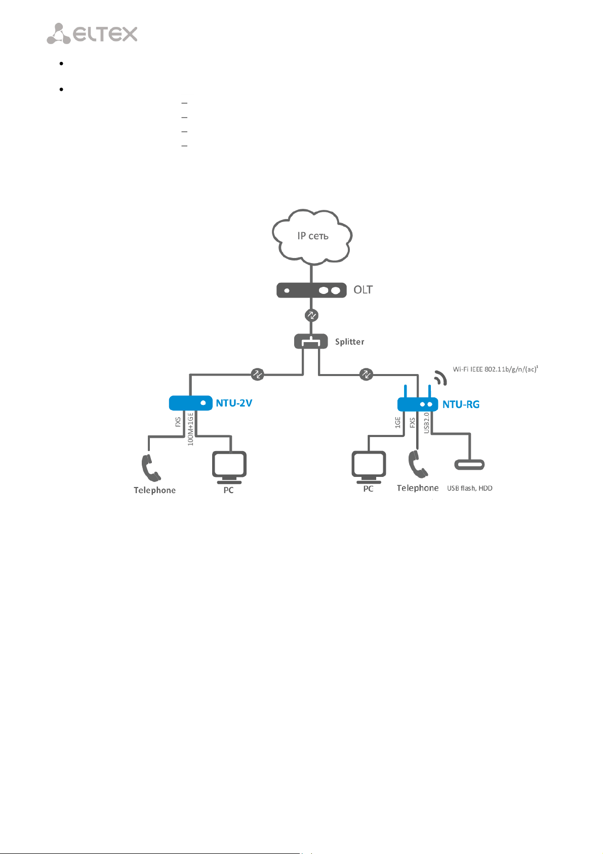
The range of ONT NTU equipment produced by Eltex comprises of the following terminals:
NTU-2V with two Ethernet user network interfaces (UNI) – 1 Ethernet 10/100 Base-T port, 1
Ethernet 10/100/1000 Base-T port – and one FXS port;
NTU-RG-1402G-W, which are designed to support four UNI: 10/100/1000Base-T, FXS, Wi-Fi, and
USB.
The Operation Manual describes application, key specifications, configuration, monitoring, and software
retrofit for NTU-RG optical terminals and NTU-2V devices.
____________________________________________________________________________________
NTU-2V, NTU-RG Optical Network Terminals 5
Page 6

____________________________________________________________________________________
Model Name
WAN
LAN
FXS
Wi-Fi
USB
NTU-2V
1xGPON
1х1Gigabit
1х100Megabit
1 - -
NTU-RG-1402G-W
1xGPON
4х1Gigabit
2 + 2
NTU-RG-1402G-Wac
1xGPON
4х1Gigabit
2 + 2
2 DEVICE DESCRIPTION
2.1 Application
NTU-2V and NTU-RG GPON ONT (Gigabit Ethernet Passive Optical Network) devices represent highperformance network terminals designed for connection with upstream GPON equipment and providing end
user with broadcast access services. GPON connection is established through PON interface, while Ethernet
interfaces are used for connection of terminal equipment.
The key GPON advantage is the optimal use of bandwidth. The technology is the next step of high-speed
Internet applications for home and office. Being designed for home or office network deployment, these ONT
devices provide users, who live and work in distant flat buildings and business centres, with reliable connection
with high throughput at large distances.
An integrated router allows local network equipment to be connected to a broadband access network.
The terminals protect PCs from DoS and virus attacks with the help of firewall and filter packets to control access
based on ports and MAC/IP addresses of source and target. Users can configure a home or office web site by
adding a LAN port into DMZ. Parental Control enables filtration of undesired web sites, blocks domains and
allows for compilation of a schedule of Internet use. Virtual private network (VPN) provides mobile users and
branch offices with a protected communication channel for connection to a corporate network.
FXS ports enable IP telephony and provide various useful features such as display of caller ID, three-way
conference call, phone book, and speed dialling. This makes dialling and call pick-up user friendly.
USB ports can be used for connection of USB devices (USB flash drives, external HDD).
NTU-RG-1402G-W network router allows Wi-Fi clients to be connected using IEEE 802.11b/g/n standard.
NTU-RG-1402G-Wac network router supports 802.11ac standard that ensures a record-breaking data transfer
rate of 1 Gbps and allows wireless network to be used for delivery of modern high-speed services to client
equipment.
2.2 Models
NTU-2V and NTU-RG devices are designed to support various interfaces and features (see Table 1).
Table 1 – Models
2.3 Device Specification
The device has the following interfaces:
RJ-11 ports for connection of analog phones:
– For NTU-RG models: 2 RJ-11 ports;
– For NTU-2V models: 1 RJ-11 port.
1 PON SC/APC port for connection to operator's network.
Ethernet RJ-45 LAN ports for connection of network devices:
– For NTU-RG models: 4 RJ-45 10/100/1000Base-T ports;
____________________________________________________________________________________
6 NTU-2V, NTU-RG Optical Network Terminals
Page 7

____________________________________________________________________________________
– For NTU-2V models: 1 RJ-45 10/100 Base-T port, 1 RJ-45 10/100/1000Base-T port.
Wi-Fi transmitter/receiver
2 USB2.01 ports for connection of external drives such as USB and HDD.
1
802.11ac2, 802.11n, 802.11b, 802.11g.
The terminal uses an external adapter for 220 V / 12 V power supply.
The device supports the following functions:
Network functions:
bridge or router mode;
PPPoE support (PAP, CHAP, MSCHAP authentication);
support of static address and DHCP (DHCP client on WAN, DHCP server
on LAN);
UPnP;
IPSec;
NAT;
Firewall;
NTP;
QoS;
IGMP-snooping;
IGMP-proxy;
Parental Control;
Storage Service.
IP telephony:
SIP protocol;
audio codecs: G.729 (A), G.711(A/U), G.723.1;
ToS for RTP packets;
ToS for SIP packets;
echo cancellation (G.164, G.165 guidelines);
silence detector (VAD);
comfortable noise generator;
DTMF signals detection and generation;
DTMF transmission (INBAND, RFC2833, SIP INFO);
fax transmission: upspeed/pass-through. G.711, T.38.
Value added services:
Call Hold;
Call Transfer;
Call Waiting notification;
Forward Unconditionally;
Forward on "No Answer";
Forward on "Busy";
Caller ID Display for ETSI FSK;
Caller ID Barring (anonymous call);
Warmline;
flexible numbering plan;
voice mail notifications (MWI);
Anonymous Call Blocking;
Call Barring;
Do not Disturb (DND).
1
NTU-RG only
2
NTU-RG-1402G-Wac only
____________________________________________________________________________________
NTU-2V, NTU-RG Optical Network Terminals 7
Page 8
____________________________________________________________________________________
Firmware update via web interface, TR-069, OMCI.
Remote monitoring, configuration, and setup:
TR-069;
web interface;
OMCI;
Telnet.
Fig. 1 shows a diagram of NTU equipment connection.
Fig. 1 – Connection of NTU-2V, NTU-RG-1402G-W
____________________________________________________________________________________
8 NTU-2V, NTU-RG Optical Network Terminals
Page 9

____________________________________________________________________________________
Supported protocols
SIP
Codecs
G.729, annex A
G.711(A/µ)
G.723.1 (5.3 Kbps)
Fax transmission: G.711, T.38
Number of interfaces
NTU-2V
2
NTU-RG
4
Socket
RJ-45
Data rate, Mbps
Autodetection, 10/100/1000 Mbps,
duplex/half-duplex
Supported standards
IEEE 802.3i 10Base-T Ethernet
IEEE 802.3u 100Base-TX Fast Ethernet
IEEE 802.3ab 1000Base-T Gigabit Ethernet
IEEE 802.3x Flow Control
IEEE 802.3 NWay auto-negotiation
Parameters of WAN Interface
Number of PON interfaces
1
Supported standards
ITU-T G.984.x Gigabit-capable passive optical networks
(GPON)
ITU-T G.988 ONU management and control interface (OMCI)
specification
IEEE 802.1Q Tagged VLAN
IEEE 802.1p Priority Queues
IEEE 802.1D Spanning Tree Protocol
Connector type
SC/APC
according to ITU-T G.984.2
Transmission medium
fibre optical cable SMF-9/125, G.652
Splitting ratio
up to 1:64
Maximum range of coverage
20 km
Transmitter:
1310 nm
Upstream connection speed
1244 Mbps
Transmitter power
from +0.5 to +5 dBm
Optical spectrum width (RMS)
1 nm
Receiver
1490 nm
Downstream connection speed
2488 Mbps
Receiver sensitivity
from -8 to -28 dBm
2.4 Key Specifications
Table 2 lists key specifications of the terminals.
Table 2 – Key Specifications
VoIP Protocols
Audio Codecs
Parameters of Ethernet LAN Interface
____________________________________________________________________________________
NTU-2V, NTU-RG Optical Network Terminals 9
Page 10

____________________________________________________________________________________
Parameters of Analog User Ports
Number of ports
NTU-2V
1
NTU-RG
2
Loop resistance
up to 2 kΩ
Dialling
pulse/frequency (DTMF)
Caller ID display
yes
Parameters of Wi-Fi Interface
Model
NTU-RG-1402G-W
NTU-RG-1402G-Wac
Standard
IEEE 802.11b/g/n
802.11a/b/g/n, 802.11a/an/ac
Frequency coverage
2.400 ~ 2.497 GHz
2400 ~ 2483.5 MHz, 4900-5850 MHz
Modulation
PSK/CCK, DQPSK, DBPSK, OFDM
BPSK, QPSK, 16 QAM, 64 QAM, 256 QAM,
CCK
Data rate, Mbps
802.11b: 11, 5.5, 2, 1
802.11g: 54, 48, 36, 24, 18, 12, 9, 6
802.11n 20 MHz BW:
130, 117, 104, 78, 52, 39, 26, 13
802.11n 40MHz BW:
270, 243, 216, 162, 108, 81, 54, 27
802.11b/g/gn: 1-13 (2412-2472 MHz)
802.11a/ac: 36-64 (5180-5320 MHz), 100-
140 (5500-5700 MHz), 149165 (5745-5825 MHz)
20 and 40 MHz: 6, 9, 12 , 18, 24, 36, 48, 54,
MCS0-MCS23, MCS0-8 NSS1, MCS0-9 NSS3
802.11n 20 MHz BW:
216.7
802.11n 40MHz BW:
450
802.11ac: 1299 Mbps (80 MHz)
Maximum transmitter output power
802.11b: 17 dBm +/-1.5 dBm
802.11g: 15 dBm +/-1.5 dBm
802.11n: 14.75 dBm +/-1.5 dBm
MAC protocol
CSMA/CA, ACK 32 MAC model
Data protection
64/128 bit WEP encryption
WPA, WPA2
802.1x
AES and TKIP
Operating system support
Windows XP 32/64, Windows Vista 32/64, Windows 2000, Windows 7 32/64
Linux, VxWorks
Number of antennas
NTU-RG-1402G-W
2
NTU-RG-1402G-Wac
3
Antenna gain
5 dBi
Operating temperature range
from 0 to +70° C
Control
Local control
web interface
Remote control
Telnet, TR-069, OMCI
Firmware update
OMCI, TR-069, HTTP, TFTP
Access restriction
password
General parameters
Power supply
12 V DC /220 AC power adapter
Power consumption
NTU-2V
5 W max.
NTU-RG-1402G-W
15 W max.
NTU-RG-1402G-Wac
15 W max.
Operating temperature range
from +5 to 40°C
Relative humidity
up to 80 %
Dimensions
NTU-2V
122×96×32 mm
NTU-RG
187x120x32 mm
Weight
NTU-2V
0.25 kg
NTU-RG
0.3 kg
____________________________________________________________________________________
10 NTU-2V, NTU-RG Optical Network Terminals
Page 11
____________________________________________________________________________________
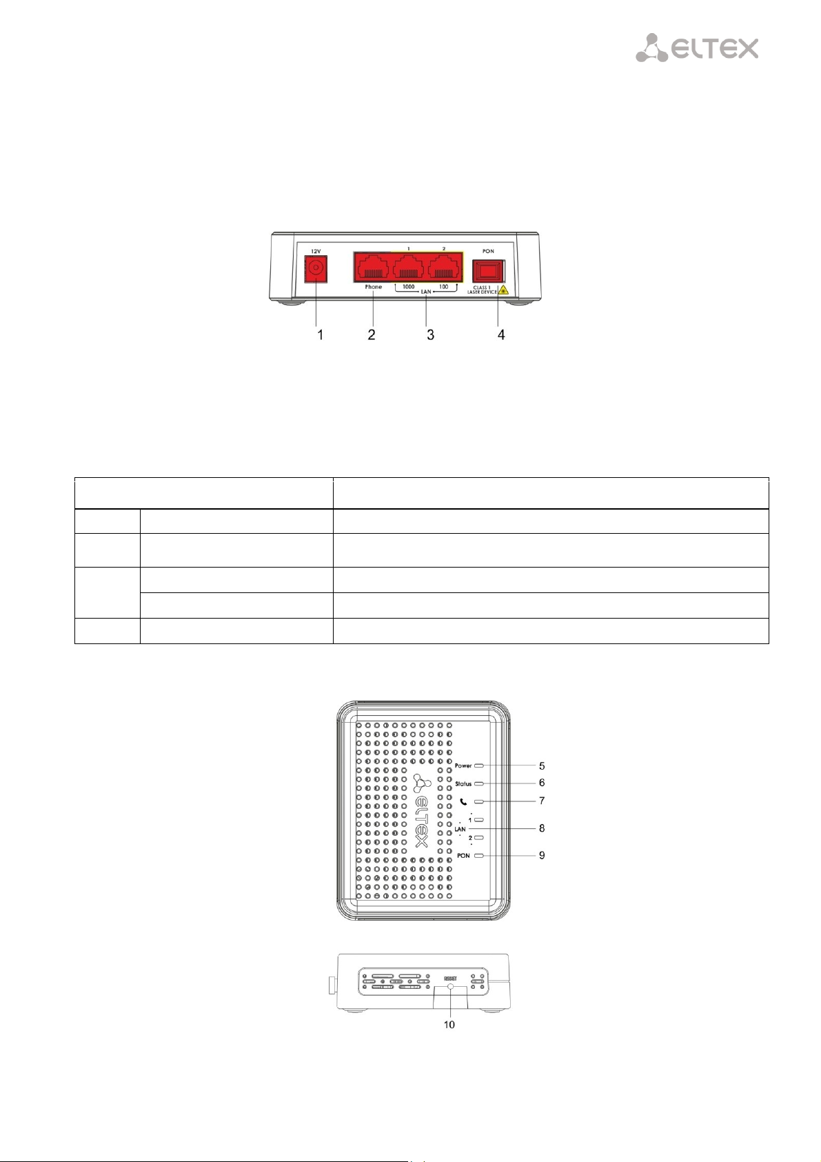
Rear Panel Element
Description
1
12V
Power adapter connector
2
Phone
RJ-11 port for connection of an analog phone
3
LAN 1000
RJ-45 10/100/1000Base-T port for connection of network devices
LAN 100
RJ-45 100Base-TX port for connection of network devices
4
PON
SC port (socket) for connection to PON with GPON interface
2.5 Design
2.5.1 NTU-2V
NTU-2V devices are designed as a 122×96×32 mm desktop device in a plastic housing.
Fig. 2 shows NTU-2V rear panel.
Fig. 2 – NTU-2V Rear Panel
Connectors and controls located on the rear panel of NTU-2V are listed in Table 3.
Table 3 – Description of LEDs and Controls Located on the Rear Panel
Fig. 3 shows NTU-2V side and top panels.
Fig. 3 – NTU-2V Side and Top Panel
____________________________________________________________________________________
NTU-2V, NTU-RG Optical Network Terminals 11
Page 12

____________________________________________________________________________________
Panel Element
Description
10
Power
power on indicator
9
Status
device authentication indicator
8
analog phone indicator
7
LAN
Ethernet ports indicator
6
PON
optical interface indicator
5
Reset
a functional key that reboots the device and resets it to factory settings
Item
Rear Panel Element
Description
1
On/Off
On/off button
2
12V
power adapter connector
3
PON
SC port (socket) for PON with GPON interface
4
USB
2 connectors for external drives and other USB devices
5
Phone 1, Phone 1
2 RJ-11 ports for connection of analog phones
6
LAN 10/100/1000 1..4
4 RJ-45 ports for connection of network devices
Controls and LED indicators located on NTU-2V side and top panels are listed in Table 4.
Table 4 – Description of LEDs and Controls Located on the Side and Top Panels
2.5.1.1 NTU-RG
NTU-RG-1402G-W network terminal is designed as a desktop device in a plastic housing.
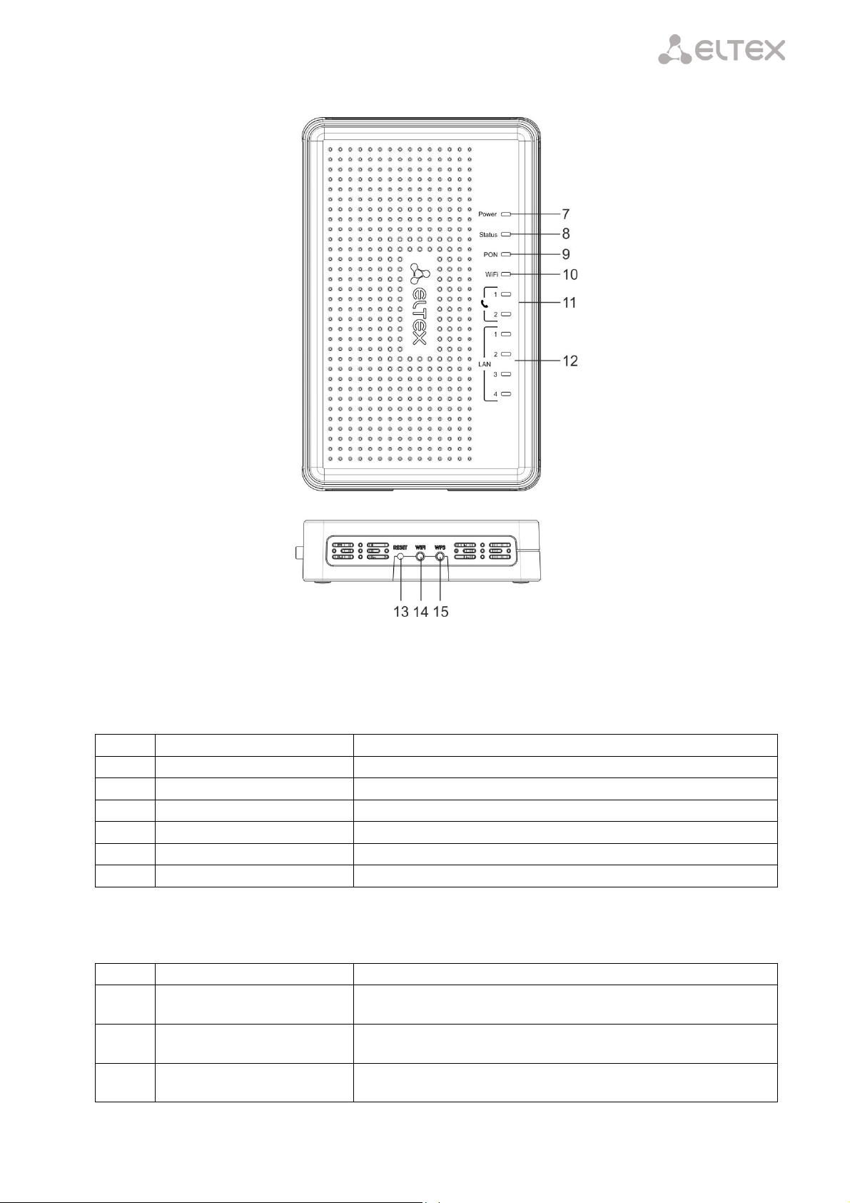
Fig. 4 shows NTU-RG-1402G-W rear panel.
Fig. 4 – NTU-RG-1402G-W Rear Panel
Connectors and controls located on the device rear panel are listed in Table 5.
Table 5 – Description of Connectors and Controls Located on the Rear Panel
____________________________________________________________________________________
12 NTU-2V, NTU-RG Optical Network Terminals
Page 13
____________________________________________________________________________________
Item
Top Panel Element
Description
7
Power
power on indicator
8
Status
device authentication indicator
9
PON
optical interface indicator
10
Wi-Fi
Wi-Fi activity indicator
11
Phone 1..2
FXS ports activity indicator
12
LAN 1..4
Ethernet ports indicator
Item
Side Panel Element
Description
13
Reset
a functional key that reboots the device and resets it to factory
settings
14
Wi-Fi
Wi-Fi on/off button
15
WPS
enables automatically protected Wi-Fi connection for device
Fig. 5 shows NTU-RG-1402G-W side and top panels.
Fig. 5 – NTU-RG-1402G-W Side and Top Panels
LEDs located on the device top panel are listed in Table 6.
Table 6 – Description of Top Panel LEDs
Buttons located on the device side panel are listed in Table 7.
Table 7 – Description of Side Panel Buttons
____________________________________________________________________________________
NTU-2V, NTU-RG Optical Network Terminals 13
Page 14

____________________________________________________________________________________
LED
LED Status
Device Status
PON
off
device booting
green
established connection between optical line terminal
and device
red
no signal from optical line terminal
LAN 1..2
green
established 10/100 Mbps connection
orange
established 1000 Mbps connection
flashes
transferring data packets
Phone
glows
phone handset is picked up
flashes
port is not registered or SIP authentication is not
completed on server
flashes slowly
receiving a call
Status
off
WAN interface is in static or bridge mode, PPP client
is not running
green
device was successfully authenticated on line
terminal (PPP session started in WAN interface)
orange
device is not authenticated (PPP session is not started
in WAN interface)
Power
off
device is disconnected from the power source or
faulty
green
current device configuration differs from the default
one
orange
default configuration is active
red
device booting
LED
LED Status
Device Status
LAN 1..4
green
established 10/100 Mbps connection
orange
established 1000 Mbps connection
flashes
transferring data packets
Phone 1..2
glows
phone handset is picked up
flashes
port is not registered or SIP authentication is not
completed on server
flashes slowly
receiving a call
2.6 Light Indication
2.6.1 NTU-2V
The PON, LAN 1..2, Phone 1, Status, and Power indicators located on the front panel show the device
current status.
Table 8 lists possible statuses of the LEDs.
Table 8 – Light Indication of Device Status
2.6.2 NTU-RG
The LAN 1..4, Phone 1..2, Wi-Fi, PON, Status, and Power indicators located on the front panel show the
device current status.
Table 9 lists possible statuses of the LEDs.
Table 9 – Light Indication of Device Status
____________________________________________________________________________________
14 NTU-2V, NTU-RG Optical Network Terminals
Page 15

____________________________________________________________________________________
Wi-Fi
green
Wi-Fi is active
flashes
Wi-Fi data transfer
off
Wi-Fi is not active
PON
off
device booting
green
established connection between optical line terminal
and device
red
no signal from optical line terminal
Status
off
WAN interface is in static or bridge mode, PPP client
is not running
green
device was successfully authenticated on line
terminal (PPP session started in WAN interface)
orange
device is not authenticated (PPP session is not started
in WAN interface)
Power
off
device is disconnected from the power source or
faulty
green
current device configuration differs from the default
one
orange
default configuration is active
red
device booting
Operation Mode
Yellow LED
Green LED
Port is in 1000Base-T mode, no data
transfer
solid on
solid on
Port is in 1000Base-T mode, data
transfer
solid on
flashes
Port is in 10/100Base-TX mode, no data
transfer
off
solid on
Port is in 10/100Base-TX mode, data
transfer
off
flashes
2.6.3 LAN Interface Indication
Table 10 lists operation modes indicated by LEDS for LAN ports on the device rear panel.
Table 10 – Light Indication of LAN Interfaces
2.7 Reboot and Reset to Factory Settings
For device reboot, press the Reset button once on the device side panel. In order to reset the device to
factory settings, press the Reset button and gold it for 7-10 seconds until the POWER LED glows red. Factory
settings for IP address are: LAN – 192.168.1.1, subnet mask – 255.255.255.0. Access can be provided from LAN 1
and LAN 2 ports.
2.8 Delivery Package
The standard delivery package of NTU-2V, NTU-RG-1402G-W includes:
— NTU-2V, NTU-RG-1402G-W optical network terminal;
— 220V/12V power adapter;
— Operation Manual.
____________________________________________________________________________________
NTU-2V, NTU-RG Optical Network Terminals 15
Page 16
____________________________________________________________________________________
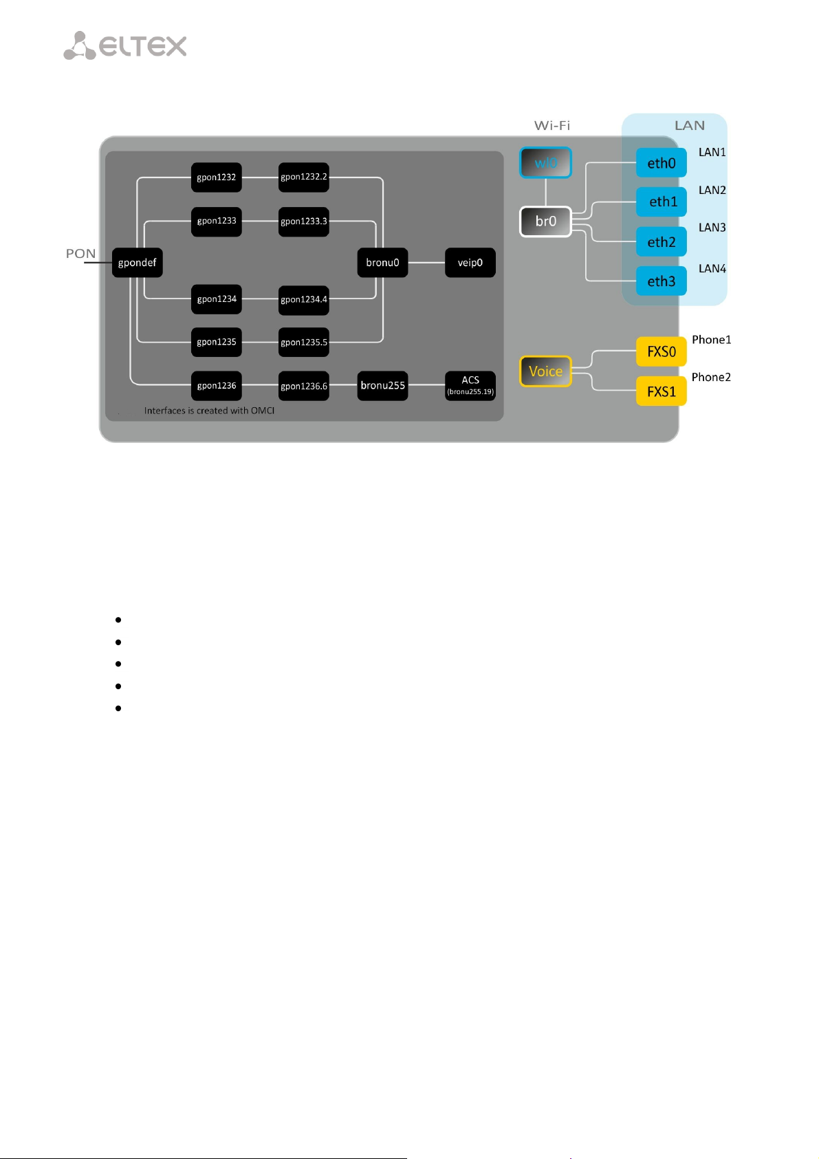
3 NTU-RG-1402G-W ARCHITECTURE
Fig. 6 – Architecture of a Device with Factory Settings
Main Components of the Device
– optical receiver/transmitter (SFF module) for conversion of an optical signal into electric one;
– processor (PON chip) which converts Ethernet and GPON interfaces;
– Wi-Fi module for wireless interface of the device.
A device with factory (initial) settings have the following logical blocks (see Fig. 6):
br0;
Voice (IP telephony);
eth0…3;
FXS0…1;
wl0.
br0 is used to combine LAN ports in one group.
The eth0..3 blocks physically represent Ethernet ports with RJ-45 connector for connection of PC, STB, and
other network devices. They are logically included into the br0 block.
The FXS0..1 blocks are ports with RJ-11 connectors for connection of analog phones. They are logically
included into the Voice block. The Voice block can be controlled through web interface or remotely with ACS
server through TR-069 protocol. The block specifies VoIP service parameters (SIP server address, phone
numbers, VAS, etc.).
The wl0 block is an interface for Wi-Fi module connection.
A connection to optical device (successful connection to an OLT) additionally create the gpondef,
gpon1232..1236, gpon1232.2..1236.6, bronu0, bronu255, veip0, and bronu255.19 (ACS) blocks with the help
of the OMCI protocol (ONT Management and Control Interface). Blocks enumeration is configured in OLT.
The ACS block is used for device remote control with the help of the ACS server (Auto Configuration
Server). The block is used for communication with subscriber's equipment and processing of queries from NTP
devices and enables services.
____________________________________________________________________________________
16 NTU-2V, NTU-RG Optical Network Terminals
Page 17

____________________________________________________________________________________
4 NTU-RG-1402G-W CONFIGURATION THROUGH WEB INTERFACE. USER ACCESS
Device configuration requires accessing the device through a web browser (a program displaying
hypertext documents) such as Firefox or Google Chrome. To do this, enter the device IP address in the browser
address bar (factory settings are 192.168.1.1, subnet mask – 255.255.255.0).
When the address is entered, the device requires user to log in.
User name: user, password: user.
In order to prevent unauthorised access to the device, the password is recommended to be changed
(see section 4.7.4 The
____________________________________________________________________________________
NTU-2V, NTU-RG Optical Network Terminals 17
Page 18

____________________________________________________________________________________
The Passwords Submenu. Access Control Configuration (Passwords).
Given below is a general view of the device configuration window. A navigation tree for object settings is in
the left pane, while the settings editor is to the right.
____________________________________________________________________________________
18 NTU-2V, NTU-RG Optical Network Terminals
Page 19

____________________________________________________________________________________
4.1 The Device Info Menu. Device Information
4.1.1 The Summary Submenu. Device General Information
– Board type – device model;
– Serial number – device serial number;
– PON serial – device serial number in PON;
– Base WAN MAC – MAC address of the device WAN;
– Board ID – PCB ID;
– Hardware Version – hardware version number;
– Software Version – software version number;
– Bootloader (CFE) Version – bootloader version number;
– Wireless Driver Version – Wi-Fi adapter version number;
– System time – current time of the device;
– Uptime – time from the last device reboot.
4.1.2 The WAN Submenu. The Status of Services
The tab contains summary of existing configurations of the WAN interface.
____________________________________________________________________________________
NTU-2V, NTU-RG Optical Network Terminals 19
Page 20

____________________________________________________________________________________
4.1.2.1 The Detail Submenu. Detailed Information
The tab contains detailed information about existing configurations of the
WAN interface.
The following information about services can be displayed:
– Interface – interface name;
– Type – interface mode;
– Connection Type – the type of connection;
– NAT – NAT status;
– Firewall – Firewall status;
– Status – connection status;
– IPv4 Address – access address;
– Default Gateway – gateway by default;
– Primary DNS Server1 – address of the primary DNS server;
– Secondary DNS ServerОшибка! Закладка не определена. – address
of the secondary DNS server;
– Bridging to – list of associated LAN interfaces.
4.1.3 The LAN Submenu. Monitoring of LAN Ports. Monitoring of Wi-Fi Interface Status
Status and parameters of wired and wireless LAN interfaces are available in this menu. Status, connection
speed, and mode (duplex/half-duplex) are shown for wired connections.
4.1.4 The Statistics Submenu. Traffic Flow Information for Ports of the Device
The menu shows statistics of received and transmitted packets for WAN Service, LAN, and optical
interface.
LAN interface:
1
For the INTERNET and VoIP services only.
____________________________________________________________________________________
20 NTU-2V, NTU-RG Optical Network Terminals
Page 21

____________________________________________________________________________________
WAN Service:
Optical interface:
If a device supports measurement of optical signal parameters1, the menu displays an additional table:
Link Status – optical link status;
Optical Signal Level – level of the received signal (1490 nm);
Transmit Optical Level – level of the transmitted signal (1310 nm);
Temperature – temperature of SFF module;
Vcc Voltage – supply voltage;
Bias Current – bias current.
In order to clear the statistics and start gathering it from the beginning, click the Reset Statistic button.
1
Optional
____________________________________________________________________________________
NTU-2V, NTU-RG Optical Network Terminals 21
Page 22

____________________________________________________________________________________
4.1.5 The Route Submenu. The Routing Table
The menu shows the routing table.
Destination – destination IP address;
Gateway – gateway IP address;
Subnet mask – subnet mask (Genmask);
Flag – routing flag:
– U – active routing;
– I – inactive routing, packets will be rejected;
– G – the routing uses gateway;
– H – destination is a separate host;
– R – restored routing;
– D – the routing was created after receiving a redirected ICMP message;
– M – the routing was changed by a redirected ICMP message;
Metric – routing priority;
Service – a service the routing is associated with;
Interface – an interface the routing is associated with.
4.1.6 The ARP Submenu. Display of the ARP Protocol Cache
The ARP efficiency depends a lot on ARP cache presented in every host. The cache contains Internet
addresses and corresponding MAC addresses. Every record is stored in cache for 5 minutes since its creation.
IP-address – client IP address;
Flags – status flags:
– Complete – active client;
– Incomplete – client does not respond to ARP queries;
HW-Address – client MAC address;
Device – client interface.
____________________________________________________________________________________
22 NTU-2V, NTU-RG Optical Network Terminals
Page 23

____________________________________________________________________________________
4.1.7 The DHCP Submenu. Active DHCP Leases
The DHCP table provides a list of active DHCP leases and their duration.
Hostname – host name (network device);
MAC Address – device MAC address;
IP Address – device address in local network that was chosen by router from the pool of IP addresses;
Expires In – remaining time of the address lease.
4.1.8 The Wireless Stations Submenu. Connected Wireless Devices
The menu shows a list of authenticated wireless devices and their statuses.
The device information is shown in a table with the following parameters:
MAC – device MAC address;
Associated – SSID association status;
Authorized – authorisation status;
SSID – ID of the network the client is associated with;
Interface – access interface.
Click the Refresh button to refresh the information.
____________________________________________________________________________________
NTU-2V, NTU-RG Optical Network Terminals 23
Page 24

____________________________________________________________________________________
4.1.9 The Voice Submenu. Monitoring of Telephone Ports
The menu shows the status of FXS ports and parameters of SIP accounts.
Voice daemon status – the status of voice daemon;
SIP Proxy – SIP Proxy address and port;
SIP Outbound Proxy – address and port of the SIP proxy which will be used to transfer all queries (this
server will be used for routing of SIP Proxy and SIP Registrar queries);
SIP Registrar – SIP server address and port;
SIP Account – SIP account (FXS port number);
Account enabled – the status of FXS port in configuration;
Status – authentication status;
Error – SIP server error;
Response code – SIP server response code;
Extension – phone number;
Display name – user name displayed;
Authentication name – user name for authentication.
____________________________________________________________________________________
24 NTU-2V, NTU-RG Optical Network Terminals
Page 25

____________________________________________________________________________________
4.2 The PPPoE Menu. PPP1 Settings
Set the Enable Service flag to turn a service on.
The Internet service has 2 modes of operation:
1. IP_Routed – PPPoE sessions starts on subscriber device;
2. PPPoE_Bridged – PPPoE session starts on user PC.
Username – user name for Internet access;
Password – password for Internet access;
The Username and Password fields are not available in the PPPoE_Bridged mode. The user name and
password are entered in user PC.
Click the Apply/Save button to accept and save the changes.
4.3 The Advanced Setup Menu. Advanced Configuration
4.3.1 The LAN Submenu. Configuration of Main Parameters
The menu allows configuration of main parameters of the LAN interface.
IP address – device address in local network;
Subnet Mask – subnet mask.
1
If the menu is not presented in configuration, the parameters have already been configured by you operator.
____________________________________________________________________________________
NTU-2V, NTU-RG Optical Network Terminals 25
Page 26

____________________________________________________________________________________
DHCP Server
DHCP Server (Dynamic Host Configuration Protocol) allows local PCs to be automatically configured for a
network. The server assigns an IP address to every computer in the network. This option does away with the
need for manual IP assignment.
Enable – being set, indicates that the DHCP server will be used (IP addresses from the range given below
will be dynamically assigned to network devices);
Start IP Address – the first address of the range;
End IP Address – the last address of the range;
Leased Time (hour) – address lease time in hours.
Static IP Lease List
This table associates the assigned IP addresses with MAC addresses of devices. Click Add to add a new
record to the table. The table supports up to 32 associations.
MAC Address – device MAC address;
IP Address – device IP address.
Click the Apply/Save button to accept and save the changes.
4.3.2 The Port Mapping1 Submenu. Distribution Configuration for Ports and Services
The menu is used to configure Ethernet ports for specific
services provided by operator that allows separation of
different traffic types. The function is mainly used in Triple Play
networks.
The menu allows changes in the current associations
between ports and services. For example, it allows 4 ports to be
configured for INTERNET and 3 ports to be configured for STB
unlike the default configuration shown above.
Click the Apply/Save button to accept and save the
changes.
4.3.3 The NAT Submenu. NAT Settings
The use of the NAT settings can be efficient when the device operates in the router mode.
4.3.3.1 The Virtual Servers Submenu. Settings of Virtual Servers
Virtual Server is a router function designed to provide users with Internet access to servers located in your
local network, e. g. to mail servers, WWW, and FTP. A device may have up to 32 records.
1
If the menu is not presented in configuration, the parameters have already been configured by you operator.
____________________________________________________________________________________
26 NTU-2V, NTU-RG Optical Network Terminals
Page 27

____________________________________________________________________________________
A Virtual Server rule will not work if a query to IP address of WAN interface was received from a local
network because the device does not support the NAT Loopback function. Virtual Server rules should
be tested only in Internet.
In order to add a record to the filtration table, click Add and fill in the fields of the displayed window.
Use Interface – the used interface;
Available are only the interfaces configured to work in the router mode with enabled translation of
network addresses.
– Service Name – service settings:
– Select a Service – select a preconfigured rule;
– Custom Service – create new rules not listed in the Select a Service list;
– Server IP Address – IP address of the server in local network;
External Port Start – the first port in the port range accessed from Internet;
____________________________________________________________________________________
NTU-2V, NTU-RG Optical Network Terminals 27
Page 28

____________________________________________________________________________________
External Port End – the last port in the port range accessed from Internet;
– Protocol – the network protocol selected;
Internal Port Start – the first internal port in the port range, which will receive redirected traffic from
external port of router;
Internal Port End – the last internal port in the port range, which will receive redirected traffic from
external port of router;
Click the Apply/Save button to accept and save the changes.
4.3.3.2 The Port Triggering Submenu. Port Triggering Configuration
Router blocks all incoming connection requests by default. The Port Triggering function dynamically opens
ports of external interface when a definite event occurs. The ports are then associated with corresponding PC
ports in local network.
In order to add rules to the table, click the Add button. Click Remove in front of a selected rule to remove
it.
– Use Interface – the used interface.
Available are only the interfaces configured to work in the router mode with enabled translation of
network addresses.
– Application Name – application settings:
– Select an application – select a preconfigured rule;
– Custom an application – create new rules not listed in the Select an application list.
____________________________________________________________________________________
28 NTU-2V, NTU-RG Optical Network Terminals
Page 29

____________________________________________________________________________________
As opposed to the Virtual Server function, PC's IP address should not be fixed in LAN.
– Trigger Port Start – the first port in the port range which perform the trigger function;
– Trigger Port End – the last port in the port range which perform the trigger function;
– Trigger Protocol – the protocol used for trigger;
– Open Port Start – the first port in the port range which will be opened by router;
– Open Port End – the last port in the port range which will be opened by router;
– Open Protocol – the protocol used for opened ports.
Click the Apply/Save button to accept and save the changes.
4.3.3.3 The DMZ Host Submenu. DMZ Settings
When an IP address is set to the DMZ Host IP Address field, all requests from external network that do not
satisfy the Virtual Servers rules will be redirected to a DMZ host (a trusted host with the specified address in the
local network).
Delete the IP address in the field to disable this option.
Click the Apply/Save button to accept and save the changes.
4.3.4 The Security Submenu. Security Settings
This submenu allows configuration of device security settings.
4.3.4.1 The IP Filtering Submenu. Filtering Settings for Addresses
The IP Filtering function filters router traffic by IP addresses and ports.
Filtration Settings for Outgoing Traffic
All outgoing traffic will be transmitted by default. Rules created in the menu allow filtration of
undesired traffic.
____________________________________________________________________________________
NTU-2V, NTU-RG Optical Network Terminals 29
Page 30

____________________________________________________________________________________
Click the Add button to add a new filtration rule.
– Filter Name – filter text description;
– IP Version – IP protocol version;
– Protocol – selected protocol (TCP/UDP, TCP, UDP, ICMP);
– MAC address – source MAC address;
– Source IP address[/prefix length] – source IP address (prefix length can be specified after slash);
– Source Port (port or port:port) – source port or a range of ports separated by a colon;
– Destination IP address[/prefix length] – destination IP address (prefix length can be specified after
slash);
– Destination Port (port or port:port) – destination port or a range of ports separated by a colon.
Click the Apply/Save button to accept and save the settings.
Filtration Settings for Incoming Traffic
When a firewall is turned on in a WAN or LAN interface, all incoming traffic which does not satisfy the
set rules will be blocked.
____________________________________________________________________________________
30 NTU-2V, NTU-RG Optical Network Terminals
Page 31

____________________________________________________________________________________
Click the Add button to add a new filtration rule.
– Filter Name – filter text description;
– IP Version – IP protocol version;
– Protocol – the network protocol selected;
– Source MAC address – source MAC address;
– Source IP address[/prefix length] – source IP address (prefix length can be specified after slash);
– Source Port (port or port:port) – source port(s);
– Destination IP address[/prefix length] – destination IP address (prefix length can be specified after
slash);
– Destination Port (port or port:port) – destination port(s);
WAN (configured in the router mode and having firewall enabled) and LAN Interfaces
– Select All – when set, allows selection of all available interfaces.
You can also select an interface from the list by setting a flag in front of it.
Click the Apply/Save button to accept and save the settings.
____________________________________________________________________________________
NTU-2V, NTU-RG Optical Network Terminals 31
Page 32

____________________________________________________________________________________
4.3.4.2 The MAC Filtering Submenu. Filtering Settings for MAC Addresses
MAC filtration allows traffic to be transferred or blocked depending on source and destination MAC
addresses.
МАС filtration can be applied only to interfaces in the bridge mode.
In order to change the global policy, set a flag in front of a corresponding interface and click the Change
Policy button. Two options are available: FORWARDED и BLOCKED.
The created rules will block traffic with specified source/destination MAC addresses in the FORWARDED
mode and allow it to pass in the BLOCKED mode.
– Protocol type – the selected protocol (PPPoE, IPv4, IPv6, AppleTalk, IPX, NetBEUI, IGMP);
– Destination MAC Address – destination MAC address;
– Source MAC Address – source MAC address;
– Frame Direction – transfer direction (LAN<=>WAN, LAN=>WAN, WAN=>LAN);
– WAN Interfaces (Configured in Bridge mode only) – allows a WAN interface to be selected from a drop-
down list (only the interfaces in the bridge mode re available).
Click the Apply/Save button to accept and save the settings.
____________________________________________________________________________________
32 NTU-2V, NTU-RG Optical Network Terminals
Page 33

____________________________________________________________________________________
The restrictions will apply if the correct system time is set for the device.
4.3.5 The Parental Control Submenu. Parental Control: Restrictions Configuration
4.3.5.1 The Time Restriction Submenu. Configuration of Session Time Restriction
The menu allows schedule configuration (days and hours) for computers use. The schedule will be used to
block Internet access for a definite computer in local network at a definite time.
Click the Add button to create a new schedule. You can add up to 16 records.
– User name – user name;
– Browser's MAC Address – automatically identified MAC address of the computer for which the
schedule is created;
– Other MAC Address (xx:xx:xx:xx:xx:xx) – manually set MAC address of the computer for which the
schedule is created;
– Days of the week – days when Internet access is blocked;
– Start Blocking Time (hh:mm) – the time when blocking starts (hh:mm);
– End Blocking Time (hh:mm) – the time when blocking ends (hh:mm).
Click the Apply/Save button to add settings to the table.
____________________________________________________________________________________
NTU-2V, NTU-RG Optical Network Terminals 33
Page 34

____________________________________________________________________________________
4.3.5.2 The Url Filter Submenu. Internet Access Restriction Settings
Url Filter – is a function of comprehensive analysis and control of access to certain Internet resources. This
parameter defines a lilts of prohibited/allowed URLs.
– URL List Type – list type:
– Exclude – prohibited URLs;
– Include – allowed URLs.
In order to add a new URL to a list, set the flag in front of the corresponding list (URL List Type) and click
the Add button.
– URL Address – URL address;
– Port Number – port number (if the field is empty, port 80 will be used).
Click the Apply/Save button to add settings to the table.
4.3.6 The Dynamic DNS Menu. Settings of Dynamic Domain Name System
Dynamic DNS (domain name system) allows information to be updated on DNS server in real time and
(optionally) automatically. There are two options for assignment of a constant domain name to a device
(computer, router, e. g. NTU-RG) having a dynamic IP address. The IP address can be assigned by IPCP in PPP
connections or in DHCP.
Dynamic DNS is often used in local networks where clients get IP addresses by DHCP and then register
their names in a local DNS server.
In order to add a record, click the Add button. Click Remove in front of a selected record to remove it.
____________________________________________________________________________________
34 NTU-2V, NTU-RG Optical Network Terminals
Page 35

____________________________________________________________________________________
— D-DNS provider – a type of D-DNS service (provider): DynDNS.org, TZO.com, ZoneEdit.com,
freedns.afraid.org, easyDNS.com, 3322.org, DynSIP.org, No-IP.com, dnsomatic.com, and
sitelutions.com;
— Custom – another provider chosen by user. In this case user will need to specify the provider's name and
address:
— Username – user name for the DDNS account;
— Password – password for the DDNS account;
— DDNS Provider Server Name – name of the DDNS provider;
— DDNS Provider URL – URL of the DDNS provider;
— Hostname – host name registered at the DDNS provider;
— Interface – access interface.
____________________________________________________________________________________
NTU-2V, NTU-RG Optical Network Terminals 35
Page 36

____________________________________________________________________________________
Depending on the chosen provider the following fields can be displayed:
— Username – user name for the DDNS account;
— Password – password for the DDNS account;
— DynDNS Type – type of the service you registered at your provider:
— Dynamic – dynamic DNS;
— Static – static DNS;
— Custom – custom DNS;
— Wildcard – if the flag is set, a special DNS record is used which is referred to all subdomains and will
correspond if a query sent to a subdomain, which does not exist. It is indicated as * in the
subdomain field, for example *.domain.tld.
— Email – e-mail for authentication;
— Key – key for the DDNS account.
Click the Apply/Save button to accept and save the changes.
4.3.7 The UPnP Menu. Automatic Setup of Network Devices
This section allows setup of the Universal Plug and Play (UPnP™) function. UPnP ensures compatibility
with network equipment, software, and peripheral devices.
____________________________________________________________________________________
36 NTU-2V, NTU-RG Optical Network Terminals
Page 37

____________________________________________________________________________________
The use of UPnP requires NAT setup on an active WAN interface.
Set the Enable UPnP flag to enable the function.
Click the Apply/Save button to accept and save the settings.
4.4 The Voice Menu. SIP Telephony Settings1
4.4.1 The SIP Basic Setting Submenu. SIP General Settings
— SIP proxy – address of the SIP server which is used for users registration;
— Use SIP Proxy – when the flag is set, the following SIP Proxy server is used:
— SIP Proxy – SIP Proxy address;
— SIP Proxy port – SIP Proxy port;
— Use SIP Outbound Proxy – when the flag is set, SIP Outbound-proxy is used to send all queries; it is not
used otherwise.
— SIP Outbound Proxy – address of the SIP proxy which will be used to transfer all queries
(this server will be used for routing of SIP Proxy and SIP Registrar queries);
— SIP Outbound Proxy port – port of the SIP proxy which will be used to transfer all queries;
— Use SIP Registrar – when the flag is set, the following SIP registration server is used:
— SIP Registrar – server address;
— SIP Registrar port – server port.
The table shows SIP parameters that are common for both FXS ports.
— SIP Account – SIP account (FXS port number);
— Enable – when the flag is set, the port is enabled;
— Number – phone number;
— Display name – user name displayed;
1
If the menu is not presented in configuration, the parameters have already been configured by you operator.
____________________________________________________________________________________
NTU-2V, NTU-RG Optical Network Terminals 37
Page 38

____________________________________________________________________________________
— Authentication name – user name for authentication;
— Password – password for authentication;
Click the Apply/Save button to accept and save the changes.
4.4.2 The SIP Advanced Setting Submenu. SIP Advanced Settings
The menu allows VAS configuration (see Appendix B – Additional Services for a detailed description).
— SIP Account – SIP account (FXS port number);
— Call waiting – when the flag is set, notification of a new incoming call is enabled;
— Call forwarding number – the number which is used for calls redirection;
— Forward unconditionally – enables unconditional forwarding;
— Forward on "busy" – enables call forwarding on "busy";
— Forward on "no answer" – enables call forwarding on "no answer";
— MWI – enables voice mail notifications;
— Call barring – when set, allows user to bar outgoing calls;
— Call barring mode – call barring mode;
— Call barring pin – password which allows outgoing calls;
— Call barring digit map – digit map which allows/bars outgoing calls;
— Warm line – being set, enables the Warm Line service which is disabled otherwise. The service allows
automatic connection without dialling immediately after phone handset is picked (hot lone)or after a
delay (warm line);
— Warm line number – warm line number;
— Warm line timeout – a delay before warm line dialling;
— Anonymous call blocking – when set, blocks calls from the subscribers whose number was not identified;
— Anonymous calling – when set, calls are anonymously made from a port (number identifying blocker);
— DND – when sets, enables the Do Not Disturb service.
Click the Apply/Save button to accept and save the changes.
____________________________________________________________________________________
38 NTU-2V, NTU-RG Optical Network Terminals
Page 39

____________________________________________________________________________________
4.5 The Wi-Fi Menu. Wi-Fi Network Setup
4.5.1 The Basic Submenu. General
This menu is intended for general setup of the LAN wireless interface and allows user to specify up to
three wireless access points.
— Enable Wireless – enables Wi-Fi on device;
— Enable Wireless Hotspot2.0 – enables Hotspot2.0 support on device;
— Hide Access Point – sets access point into the hidden mode (router will not broadcast SSID of the
wireless network in this mode);
— Clients Isolation – when the flag is set, wireless clients can not communicate to each other;
— Disable WMM Advertise – disables WMM (Wi-Fi Multimedia – a QoS for wireless networks);
— Enable Wireless Multicast Forwarding (WMF) – enables WMF;
— SSID (Service Set Identifier) – assigns a name to the wireless network (case-sensitive keyboard input);
The default name (SSID) of the wireless network is ELTEX-aaaa,
where аааа are the last 4 digits of WAN MAC. WAN MAC is labelled on the device housing.
— BSSID – МАС address of the access point;
— Country – specifies location (country);
— Country RegRev – specifies region ID (0-34 for Russia);
— Max Clients – the maximum possible number of simultaneously supported wireless connections.
Click the Apply/Save button to accept the changes.
____________________________________________________________________________________
NTU-2V, NTU-RG Optical Network Terminals 39
Page 40

____________________________________________________________________________________
4.5.2 The Security Submenu. Security Settings
The menu contains main parameters of data encryption in the wireless network. The client wireless
equipment can be configured either manually of automatically with the help of WPS.
WPS (Wi-Fi Protected Setup) – a standard developed by Wi-Fi Alliance to simplify setup of wireless
networks. The technology allows quick, secure, and simple setup of a wireless network without having in-depth
knowledge of Wi-Fi technology and encryption protocols. WPS automatically sets the network name and
configures data encryption to protect the network from unauthorised access. These operations should be
manually done without WPS.
In order to establish a connection, user simply needs to press the WPS button located on the side panel of
the device or use web configuration to enter PIN code.
WPS Setup
— Enable WPS – in order to enable WPS, select Enable in the drop-down list if the WI-FI network adapter
of your device supports this configuration mode;
— Add Client – client authentication method (the settings are applicable in the WPA-PSK and WPA2-PSK
modes only). Click the Add Enrollee button to start the authentication process;
— Use STA PIN – authentication using client PIN code;
____________________________________________________________________________________
40 NTU-2V, NTU-RG Optical Network Terminals
Page 41

____________________________________________________________________________________
Shortcomings of WPS
Wi-Fi routers supporting the WPS technology have a security vulnerability. The vulnerability can be
used to crack passwords of the WPA and WPA2 encryption protocols. The technology is vulnerable
as it allows to brute-force the 8-digit network key (PIN).
— Set Authorized Station MAC – sets MAC address of the client device in ХХ format:
ХХ: ХХ: ХХ: ХХ: ХХ;
— Use AP PIN – authentication using AP own PIN;
— Set WPS AP Mode – sets WPS mode of the access point;
— Device PIN – device own PIN (an 8-digit code generated by the device).
Manual Setup AP
— Select SSID – selects a name of a wireless network from the list;
— Network Authentication – selects a network authentication mode from the drop-down list:
– open – protection of the wireless network is disabled (only WEP key can be used in this
mode);
– Shared – allows user authentication by SSID or WEP key;
– 802.1x – enables the 802.1x standards (allows user authentication with the help of the
RADIUS authentication server; WEP key is used for encryption);
RADIUS Server IP Address – IP address of the RADIUS server;
RADIUS Port – port number of the RADIUS server. The default port is 1812;
RADIUS Key – a secret key for access to the RADIUS server;
– WPA2 – enables WPA2 (the mode uses the WPA2 protocol and requires the RADIUS
authentication server);
WPA2 Preauthentication;
Network Re-auth Interval;
WPA Group Rekey Interval – time interval (in seconds) between changes of the
WPA encryption keys. The keys are changed to increase protection of the wireless
network. If you do not need to change the keys, set 0 to the field.
RADIUS Server IP Address – IP address of the RADIUS server;
RADIUS Port – port number of the RADIUS server. The default port is 1812;
RADIUS Key – a secret key for access to the RADIUS server;
WPA/WAPI Encryption – selects a WPA/WAPI data encryption method: TKIP+AES,
AES:
– TKIP – the encryption protocol used for WPA. It implements a more
efficient mechanism of key change management in comparison with WEP;
– AES – an algorithm of 128-bit clock encryption with a key of
128/192/256 bits that is generally used for WPA2;
– WPA2-PSK – enables WPA2-PSK (the mode uses the WPA2 protocol but does not require the
RADIUS authentication server);
WPA/WAPI passphrase – a secret phrase. Sets a password; a string of 8-63 ASCII
characters. Follow the Click here to display link to show the secret phrase; the
password will be displayed in a pop-up window.
____________________________________________________________________________________
NTU-2V, NTU-RG Optical Network Terminals 41
Page 42

____________________________________________________________________________________
The network key corresponds to the device serial number by default.
The serial number is labelled on the device housing. When you change
the password, you will need to specify a combination of 10 characters.
The password must contain digits and Latin characters in upper and
lower cases.
The network key corresponds to the device serial number by default.
The serial number is labelled on the device housing. When you change
the password, you will need to specify a combination of 10 characters.
The password must contain digits and Latin characters in upper and
lower cases.
WPA Group Rekey Interval – time interval (in seconds) between changes of the
WPA encryption keys. The keys are changed to increase protection of the wireless
network. If you do not need to change the keys, set 0 to the field;
WPA/WAPI Encryption – selects a WPA/WAPI data encryption method: TKIP+AES,
AES:
– TKIP – the encryption protocol used for WPA. It implements a more
efficient mechanism of key change management in comparison with WEP;
– AES – an algorithm of 128-bit clock encryption with a key of
128/192/256 bits that is generally used for WPA2;
– Mixed WPA2/WPA – enables the WPA2/WPA combination (this encryption mode uses the
WPA2 and WPA encryption protocols and requires the RADIUS authentication server);
WPA2 Preauthentication – pre-authentication of the wireless client in other
wireless access points in the specified range. Connection is established at the
current wireless access point during the verification.
Network Re-auth Interval – time interval for repeated authentication. The
parameter defines how often the access points sends an authentication message to
clients and requires a reply with correct authentication data;
WPA Group Rekey Interval – time interval (in seconds) between changes of the
WPA encryption keys. The keys are changed to increase protection of the wireless
network. If you do not need to change the keys, set 0 to the field.
RADIUS Server IP Address – IP address of the RADIUS server;
RADIUS Port – port number of the RADIUS server. The default port is 1812;
RADIUS Key – a secret key for access to the RADIUS server;
WPA/WAPI Encryption – selects a WPA/WAPI data encryption method: TKIP+AES,
AES:
– TKIP – the encryption protocol used for WPA. It implements a more
efficient mechanism of key change management in comparison with WEP;
– AES – an algorithm of 128-bit clock encryption with a key of
128/192/256 bits that is generally used for WPA2;
– Mixed WPA2/WPA-PSK – enables the WPA2/WPA-PSK combination (this encryption mode
uses the WPA2-PSK and WPA-PSK encryption protocols and does not require the RADIUS
authentication server);
WPA/WAPI passphrase – a secret phrase. Sets a password; a string of 8-63 ASCII
characters. Follow the Click here to display link to show the secret phrase; the
password will be displayed in a pop-up window.
WPA Group Rekey Interval – time interval (in seconds) between changes of the
WPA encryption keys. The keys are changed to increase protection of the wireless
network. If you do not need to change the keys, set 0 to the field.
____________________________________________________________________________________
42 NTU-2V, NTU-RG Optical Network Terminals
Page 43

____________________________________________________________________________________
WPA/WAPI Encryption – selects a WPA/WAPI data encryption method: TKIP+AES,
AES:
– TKIP – the encryption protocol used for WPA. It implements a more
efficient mechanism of key change management in comparison with WEP;
– AES – an algorithm of 128-bit clock encryption with a key of
128/192/256 bits that is generally used for WPA2;
Make sure that PC's wireless adapter supports the selected encryption type.
The most secure protection of a wireless channel is reached by joint operation of access point and
RAIUS server (for authentication of wireless clients).
— WEP Encryption – select Enable in the drop down list to enable WEP encryption;
— Encryption Strength – 64- or 128-bit key encryption;
— Current Network Key – the key that will be used for connection;
— Network Key 1..4 – allows specification of 4 different keys, which comprise of 10 hex
characters of 5 ASCII characters1 for 64-bit encryption. Other options are 26 hex characters or
13 ASCII characters for 128-bit encryption.
Click the Apply/Save button to accept the changes.
4.5.3 The MAC Filter Submenu. Filtering Settings of MAC Addresses
The menu allows filters configuration for MAC addresses.
– Select SSID – the identifier of the wireless network, for which a rule will be created;
– MAC Restrict Mode – filtration mode for MAC addresses:
– Disabled – filter is disabled;
– Allow – filters allowed addresses;
– Deny – filters denied addresses.
In order to add a MAC address to the filtration table, click Add and enter the address into the MAC
address field of the displayed menu.
Click the Apply/Save button to accept the changes.
1
ASCII—is a set of 128 characters for machine representation of capital and lower case Latin characters, digits, punctuation
marks, and special symbols.
____________________________________________________________________________________
NTU-2V, NTU-RG Optical Network Terminals 43
Page 44

____________________________________________________________________________________
Router does not support the Wi-Fi Multimedia (WMM) function in the bridge mode.
4.5.4 The Wireless Bridge Submenu. Configuration of Wireless Connection in the Bridge Mode
The menu specifies an operation mode of access point: either access point or wireless bridge.
When the bridge mode is used, MAC addresses of remote bridges should be specified. The mode is used
for a wireless connection between two independent networks.
The Wireless Bridge mode has the following settings:
– Bridge Restrict – the bridge mode to be used:
– Enabled – enable filtering for MAC addresses (only specified addresses are allowed);
– Enable(Scan) – search for remote bridges;
– Disable – no restrictions for MAC addresses;
– Remote Bridges MAC Address – addresses of remote bridges.
Click Refresh to refresh information on available remote bridges.
Click the Apply/Save button to accept and save the changes.
____________________________________________________________________________________
44 NTU-2V, NTU-RG Optical Network Terminals
Page 45

____________________________________________________________________________________
4.5.5 The Advanced Submenu. Advanced Settings
The menu allows advanced configuration of wireless network.
– Band – frequency coverage;
– Channel – active channel of the router. Interference or any other issues of a wireless network may
be solved by changing the channel. The parameter is recommended to be set to Auto in order to
avoid interference caused by adjacent networks.
– Auto Channel Timer (min) – time period (in min.) after which the router will search for an optimal
wireless channel. The parameter becomes available when the Channel value is set to Auto (0 –
disable);
– 802.11n/EWC – compatibility mode for 802.11n Draft2.0 and EWC (Enhanced Wireless
Consortium) equipment;
– Bandwidth – bandwidth of 20 MHz or 40 MHz. When set to 40 MHz, 2 adjacent bandwidth of 20
MHz are used to broaden the channel's throughput;
– Control Sideband – the second channel (Lower or Upper) for the 40 MHz option;
– 802.11n Rate – connection rate;
– 802.11n Protection – when enabled, enhances protection but decreases throughput;
– Support 802.11n Client Only – when enabled, denies 802.11b/g clients to access the device;
– RIFS Advertisement – reduced Interframe Space, reduces interval between data units (PDUs),
increases Wi-Fi efficiency;
____________________________________________________________________________________
NTU-2V, NTU-RG Optical Network Terminals 45
Page 46

____________________________________________________________________________________
– OBSS Co-Existence – tolerance setting for the chosen mode (20 MHz or 40 MHz. When set to
Enable, chooses an optimal mode of operation taking into account the Bandwidth parameter; the
mode will depend only on the Bandwidth parameter otherwise;
– RX Chain Power Save – disables one of the device's antennas to save energy;
– RX Chain Power Save Quiet Time – time period during which the traffic intensity should be lower
than PPS for the power saving mode to be enabled;
– RX Chain Power Save PPS – the upper limit of PPS (packet per second). If the packets intensity of
the WLAN interface does not exceed this value during the time specified in RX Chain Power Save
Quiet Time, the power saving mode is turned on;
– 54g™ Rate – connection rate in the 54g™ compatibility mode;
– Multicast Rate – multicast traffic rate;
– Basic Rate – basic data rate;
– Fragmentation Threshold – fragmentation threshold in bytes. If a packet size exceeds the value,
the packet will be fragmented into parts of corresponding size;
– RTS Threshold – if a packet size is lower than the set RTS threshold value, the RTS/CTS mechanism
will not be used (channel connection using "ready to send"/"ready to receive" signals);
– DTIM Interval – time period after which broadcast and multicast packets in buffer will be delivered
to wireless clients;
– Beacon Interval – time period after which an information packet is sent to the wireless network to
confirm the access point is active;
– Global Max Clients – the maximum number of wireless clients;
– XPress™ Technology – allows increase of wireless throughput up to 27 % in 802.11g networks.
XPress™ Technology can increase the throughput up to 75 % in mixed networks (802.11g and
802.11b);
– Transmit Power – the transmit power of the access point;
– WMM (Wi-Fi Multimedia) – enables the Wi-Fi Multimedia (WMM) mode. The mode allows fast
and quality transmission of audio and video content simultaneously with data transmission;
– WMM No Acknowledgement – the receiving side does not acknowledge packets in this mode. This
increases transmission efficiency of low-interference medium, however decreases the efficiency of
high-interference one;
– WMM APSD – enables automatic switching to the power saving mode;
– Wireless Mode – the operating mode:
– Access Point – the access point operating mode;
– Wireless Ethernet – a mode supporting Wireless Ethernet for joining network segments;
– URE – uses the access point/router as a repeater. The mode is used to connect two wireless points
in case direct connection is not possible;
– URE Mode – the repeater mode selected (bridge (Range Extender), Routed (Travel Router));
– STA Retry Time (sec) – time period during which the access points tries to establish connection
with a Wi-Fi client.
Click the Apply/Save button to accept and save the changes.
4.6 The Storage Service Menu. File Storage Services
4.6.1 The Storage Device Info Submenu. Information on Connected Devices
The menu lists all available connected storage devices. The following information is provided:
____________________________________________________________________________________
46 NTU-2V, NTU-RG Optical Network Terminals
Page 47

____________________________________________________________________________________
– Volumename – device name;
– FileSystem – type of file system;
– Total Space – total storage space;
– Used Space – used space;
– Unmount – the button should be clicked to safely disconnect a connected device.
4.6.2 The User Accounts Submenu. Configuration of Samba Users
The menu allows configuration of Samba accounts.
Click the Add button to add a record. In order to remove a record, set the flag in the Remove column in
front of the corresponding record and click the Remove button.
— Username – log-in used to access a network resource;
— Password – password used to access the network resource;
— Confirm Password – password confirmation;
— volumeName – path to the network resource (name of the connected storage device is shown in
the Storage Device Info tab).
4.7 The Management Menu. Device Management
4.7.1 The Restore Default Submenu. Restore Default Settings
The menu allows the default settings to be restored. The device will be rebooted in this case.
This will also cancel all changes made in device default settings.
Click the Restore Default Settings button to reset the device to factory settings. The device will be
rebooted in this case.
____________________________________________________________________________________
NTU-2V, NTU-RG Optical Network Terminals 47
Page 48

____________________________________________________________________________________
Choosing the Other option in the drop-down list of servers activates a window to the right
where the address of the precision time server should be manually entered.
4.7.2 The Internet Time Submenu. System Time Settings
The tab contains settings for system time.
– Automatically synchronize with Internet time servers – being set, enables automatic synchronisation
with Internet precision time servers;
– First NTP time server – the main precision time server;
– Second NTP time server – the second precision time server (none – do not use supplementary servers);
– Third NTP time server – the third precision time server (none – do not use supplementary servers);
– Fourth NTP time server – the fourth precision time server (none – do not use supplementary servers);
– Fifth NTP time server – the fifth precision time server (none – do not use supplementary servers);
– Time zone offset – time zone according to UTC.
4.7.3 The Ping Submenu. Checking the Availability of Network Devices
The menu is intended for using the Ping utility to check availability of the network devices connected to
the router.
In order to check availability of a connected device, enter its IP address into the field and click the Ping
button. Click the TraceRoute button to view the route tracing. The information will be displayed on this page of
the web interface.
____________________________________________________________________________________
48 NTU-2V, NTU-RG Optical Network Terminals
Page 49

____________________________________________________________________________________
4.7.4 The Passwords Submenu. Access Control Configuration (Passwords)
The menu allows user to change the password used to access the device.
In order to change a password, enter the current password, then enter a new password and confirm it.
Click the Apply/Save button to accept and save the changes.
4.7.5 The System Log Submenu. Display and Configuration of the System Log
4.7.5.1 The Configuration Submenu. System Log Configuration
The menu is used for configuration of router's events.
– Log – enable/disable system log;
– Log Level – verbosity of the event log. Severity levels in the descending order:
– Emergency;
– Alert;
– Critical;
– Error;
– Warning;
– Notice;
– Informational;
– Debugging;
– Display Level – display level of the event log messages;
– Mode – the log's operating mode:
– Local – all events a returned to the router through the buffer;
– Remote – all events are returned to the Syslog server;
– Both – both modes are enabled;
– Flash – sends events to a USB drive;
– Linux Level Console Display Level (printk) – display level of messages in Linux console;
____________________________________________________________________________________
NTU-2V, NTU-RG Optical Network Terminals 49
Page 50

____________________________________________________________________________________
– Send CMS logs to syslog (require reboot) – enables/disables CMS messages transmission to the system
log.
The following settings are available in the Remote mode:
– Server IP address – IP address of the Syslog server which stores all events;
– Server IP Port – port number of the Syslog server.
Click the Apply/Save button to accept and save the changes.
4.7.5.2 The View Submenu. System Log Display
The menu is used to configure display of router's events.
Click Close to close the log display window. Use the Refresh button to refresh the information.
4.7.6 The Update Software Submenu. Software Update
In order to update software, select the software in the Software File name field (use the Choose a File or
Browse buttons) and click Update Software.
Do not switch off or reboot the device during software update. The process may take several minutes.
The device will be automatically rebooted when the update is completed.
4.7.7 The Reboot Submenu. Device Reboot
Click the Reboot button to reboot the device. The device reboot may take several minutes.
____________________________________________________________________________________
50 NTU-2V, NTU-RG Optical Network Terminals
Page 51

____________________________________________________________________________________
Problem
Possible Cause
Solution
Entering the router's IP
address (e.g. 192.168.1.1)
does not provide access
to the web interface
The PC does not belong to
the IP subnetwork for
connection to the web
interface
Set the Obtain an IP address automatically
parameter in Internet Connection Properties of your
computer
The installed web browser
has Java script disabled
Enable Java script or use another web browser
Defective cable
Check physical connection by checking status LEDs
(all LEDs should be on). If the LEDs are off, use
another cable or connect to another port of the
device if available. If your computer is switched off,
LEDs may also be off.
Access denied by your
firewall
Disable firewall on your computer
Error signal in the phone
connected to the FXS port
Invalid port configuration
Check settings in the VoIP menu (see section 4.4.2
The SIP Advanced Setting Submenu. SIP Advanced
Settings)
Forgotten/incorrect
password to web
interface of the device
_________
Reset the router to default settings using the F
button on the rear panel. Unfortunately, all changes
you made in settings will be lost in this case.
APPENDIX A – POSSIBLE PROBLEMS AND OPTIONS FOR THEIR SOLUTION
____________________________________________________________________________________
NTU-2V, NTU-RG Optical Network Terminals 51
Page 52

____________________________________________________________________________________
APPENDIX B – ADDITIONAL SERVICES
1. Call Waiting Notification
The service uses a definite signal to notify user about a new incoming call when the line is already busy
with another call.
Having received the signal, the user may decide to pick up the waiting call.
The service can be chosen in the menu with user port settings in the VoIP/SIP Advanced Setting tab (see
section 4.4.2 The The SIP Advanced Setting Submenu. SIP Advanced Settings) by setting the Call waiting flag.
When you receive the new call notification while you are already talking, press R to hold the current call
and take the waiting one. All further pressing of the R button will be processed according to the algorithms
described in sections 2 Call Transfer and 3 Conference.
– R – a flash release.
2. Call Transfer
The Calltransfer service allows temporary interruption of connection with active subscriber (subscriber A),
connection to another subscriber (subscriber C), and transfer of the call with disconnection of subscriber B (the
subscriber providing the service).
The service description:
While being connected to the subscriber A, hold the call by pressing the flash release (R), wait for the
"station response" signal, and dial the subscriber C. When the subscriber C answers your call, hang up.
3. Conference
Conference is a service allowing three and more subscribers to have shared phone conversation.
The service description:
While being connected to the subscriber A, hold the call by pressing the flash release (R), wait for the
"station response" signal, and dial the subscriber C. When the subscriber C answers your call, press R to switch
to the conference mode.
The subscriber who starts the conference is a chairperson; the rest two subscribers are participants. When
the chairperson presses flash release in the conference mode, the last called subscriber is disconnected. A
participant may put on hold other participants.
The conference ends when the chairperson hangs up; the rest two participants will receive the release
signal in this case. If a participant leaves the conference, the chairperson and another participant are switched
to a normal two-party call.
4. Message Waiting Indication (MWI) – Notification about Voice Mail
If a voice message is left on server for a subscriber, the service allows the subscriber to be timely notified
about the message. When the MWI service is enabled and there is an new message on server, the subscriber will
hear a discontinuous buzzer when he picks up the phone.
In order to enable the MWI service, set the flag in the MWI field of the corresponding port on the VoIP/SIP
Advanced Setting tab (see section 4.4.2 The SIP Advanced Setting Submenu. SIP Advanced Settings).
____________________________________________________________________________________
52 NTU-2V, NTU-RG Optical Network Terminals
Page 53

____________________________________________________________________________________
5. Call Barring
The service allows phone access restriction to a certain types of outgoing calls.
The service can be configured in the menu with user port settings in the VoIP/SIP Advanced Setting tab
(see section 4.4.2 The SIP Advanced Setting Submenu. SIP Advanced Settings) by setting the Call barring flag
and specifying the required parameters in the Call barring mode and Call barring digit map fields.
Three options of calls restriction are available depending on the parameter specified in the Call barring
mode field:
Allow all – all outgoing calls are allowed;
Deny all – all outgoing calls are denied;
Deny by digit map – denied are only the calls to the number specified in the Call barring digit map
field.
The service description:
The Call barring digit map field is set to 1150. In order to deny all outgoing calls, choose the Deny all
option in the Call barring mode field. In order to allow all outgoing calls, choose the Allow all option. In order to
deny all calls to 1150, specify Deny by digit map in the Call barring mode field.
____________________________________________________________________________________
NTU-2V, NTU-RG Optical Network Terminals 53
Page 54

____________________________________________________________________________________
ACCEPTANCE CERTIFICATE AND WARRANTY
NTU________________ Optical Network Terminal with serial number ____________________ meets the
requirements of technical specification TU6650-098-33433783-2013 and is classified as fit for operation.
The manufacturer, OOO Eltex Enterprise, guarantees that the subscriber gateway meets the requirements of
technical specification TU6650-098-33433783-2013 provided its operation conditions correspond to the ones set
forth in this Manual.
The warranty period is 1 year.
The device does not contain precious materials.
Director A. N. Chernikov
Head of the Quality Control Department S. I. Igonin
signature
signature
Name
Name
____________________________________________________________________________________
54 NTU-2V, NTU-RG Optical Network Terminals
Page 55

____________________________________________________________________________________
____________________________________________________________________________________
NTU-2V, NTU-RG Optical Network Terminals 55
 Loading...