

Page 1
Edition: 04.2010 · 610.48060.40.000 Original operating instructions · English
Operating Instructions L-BV7
2BV7 060
2BV7 061
2BV7 070
2BV7 071
L-Serie
L-Series
Flüssigkeitsring
Liquid Ring
Page 2

© 2010 Gardner Denver Deutschland GmbH · Industriestraße 26 · 97616 Bad Neustadt · Germany
Replication, distribution and / or editing of this document and the use and distribution of its content is
prohibited unless explicitly permitted. Violation obligates compensation for damages.
All rights reserved in case of the issue of a patent, utility patent or design patent.
Page 3

Contents
Contents
1
Glossary ..............................................................................................................................................6
2 Safety ..................................................................................................................................................7
2.1 Definitions .................................................................................................................................7
2.1.1 Safety alert symbol.......................................................................................................7
2.1.2 Signal words.................................................................................................................7
2.1.3 Graphic symbols...........................................................................................................8
2.2 General safety precautions .......................................................................................................9
2.3 Residual risks..........................................................................................................................11
3 Intended Use .....................................................................................................................................12
4 Technical Data ..................................................................................................................................13
4.1 Mechanical data......................................................................................................................13
4.2 Electrical data..........................................................................................................................16
4.3 Operating conditions ...............................................................................................................16
5 Description of Vacuum Pump/Compressor .......................................................................................18
5.1 Design .....................................................................................................................................18
5.2 Operating method ...................................................................................................................18
5.3 Operating modes.....................................................................................................................19
5.3.1 Self-priming operation ................................................................................................19
5.3.2 Operation with operating-liquid feed ..........................................................................19
6 Transport and Handling.....................................................................................................................20
7 Installation .........................................................................................................................................22
7.1 Installation ...............................................................................................................................22
7.2 Electrical connection (motor) ..................................................................................................24
7.3 Connecting pipes/hoses (vacuum pump/compressor)............................................................25
7.3.1 Inlet connection ..........................................................................................................26
7.3.2 Discharge connection.................................................................................................26
7.3.3 Operating-liquid port...................................................................................................26
7.3.4 Notes ..........................................................................................................................27
7.4 Accessories.............................................................................................................................27
8 Commissioning..................................................................................................................................28
8.1 Preparation and start-up .........................................................................................................28
8.2 Self-priming operation.............................................................................................................30
8.3 Operation with operating-liquid feed .......................................................................................31
9 Operation...........................................................................................................................................33
9.1 Self-priming operation.............................................................................................................33
9.2 Operation with operating-liquid feed .......................................................................................33
10 Shut-Down and Longer Standstills....................................................................................................34
10.1 Draining...................................................................................................................................34
10.2 Preparing for longer standstill .................................................................................................34
10.3 Storage conditions ..................................................................................................................35
11 Servicing............................................................................................................................................36
11.1 Maintenance............................................................................................................................36
11.2 Repairs/troubleshooting ..........................................................................................................39
11.3 Spare parts..............................................................................................................................41
11.3.1 Ordering nash_elmo spare parts................................................................................41
11.3.2 Ordering standardized parts.......................................................................................41
11.4 Service/After-sales service......................................................................................................41
11.5 Decontamination and Declaration of Clearance .....................................................................42
12 Disposal.............................................................................................................................................43
© Gardner Denver Deutschland GmbH 3 / 64 610.48060.40.000
Page 4

Contents
13
Accessories .......................................................................................................................................44
13.1 Flanges....................................................................................................................................44
13.2 Non-return valve......................................................................................................................44
13.3 Gas ejector..............................................................................................................................45
13.4 Liquid separator ......................................................................................................................46
13.5 Cavitation protection ...............................................................................................................49
14 Exploded View with Parts List ...........................................................................................................50
14.1 Parts list...................................................................................................................................50
14.2 Exploded view .........................................................................................................................51
EU declaration of conformity ..................................................................................................................54
Form for statement on safety .................................................................................................................55
Index.......................................................................................................................................................56
610.48060.40.000 4 / 64 © Gardner Denver Deutschland GmbH
Page 5

List of Illustrations
List of Illustrations
Fig. 1:
Dimensions .............................................................................................................................13
Fig. 2: Minimum inlet pressure/cavitation limit ...................................................................................17
Fig. 3: Design and operation of liquid-ring vacuum pumps/compressors (cross-section of operating
chamber) .................................................................................................................................18
Fig. 4: Attachment points ...................................................................................................................21
Fig. 5: Points for measuring the vibration speed................................................................................23
Fig. 6: Securing elements for bolting feet to supporting surface........................................................23
Fig. 7: Pipe/hose connection of vacuum pump/compressor ..............................................................25
Fig. 8: Self-priming operation .............................................................................................................30
Fig. 9: Setting the operating-liquid flow rate: Setting pre-pressure....................................................31
Fig. 10: Setting the operating-liquid flow rate: Measuring the volume with a graduated vessel..........31
Fig. 11: Operation with operating-liquid feed: Non-automatic operation..............................................32
Fig. 12: Operation with operating-liquid feed: Automatic operation .....................................................32
Fig. 13: Maximum permissible quantity of water entrained via the inlet connection............................32
Fig. 14: Pour in preservative and turn shaft .........................................................................................34
Fig. 15: Removing vacuum pump/compressor housing.......................................................................38
Fig. 16: Pouring in decalcifying agent and freeing shaft by turning .....................................................38
Fig. 17: Flanges....................................................................................................................................44
Fig. 18: Non-return valve......................................................................................................................44
Fig. 19: Gas ejector ..............................................................................................................................45
Fig. 20: Mounting liquid separator, Part 1 of 2 .....................................................................................47
Fig. 21: Mounting liquid separator, Part 2 of 2 .....................................................................................48
Fig. 22: Exploded view: vacuum pump/compressor section ................................................................51
Fig. 23: Exploded view: motor section .................................................................................................52
Fig. 24: Exploded view: motor section .................................................................................................53
© Gardner Denver Deutschland GmbH 5 / 64 610.48060.40.000
Page 6

Glossary
1 Glossary
In these instructions the following technical terms with the specified meaning are used:
Designation: Definition:
Vacuum pump
Compressor
Machine
Pump-motor unit
Machine set
Driving side;
D side
Non-driving side;
N side
Inlet pressure
Machine for generating a vacuum.
Machine for generating a gauge pressure.
Here: Vacuum pump or compressor.
Unit for extracting, transporting and compressing gases and/or vapors, as well as
for generating vacuum and gauge pressure. Here the drive is not considered part
of the machine.
Unit consisting of a machine and a drive motor.
Two or more machines that are interconnected with couplings and mounted on a
common base frame.
Side of the machine on which the drive is connected.
Side of the machine on which no drive is connected.
Pressure of the pumped gases/vapors on the inlet connection of the machine.
Discharge pressure;
Compression pressure
Pressure of the pumped gases/vapors at the discharge connection of the machine.
Test pressure
Pressure to which the machine is subjected when testing for leaks.
Qualified personnel Persons who, based on their training, experience and instruction, as well as their
knowledge of the pertinent standards, regulations, accident protection regulations
and operating conditions, are capable of carrying out certain tasks (e.g. start-up,
operation, maintenance, repair) and can recognize and avoid possible dangers in
the process. The required knowledge includes a knowledge of first aid and of the
on-site emergency equipment.
These persons must be authorized by the person responsible for system safety to
perform the required tasks.
610.48060.40.000 6 / 64 © Gardner Denver Deutschland GmbH
Page 7
2 Safety
2.1 Definitions
To point out dangers and important
information, the following signal words and
symbols are used in these operating
instructions:
2.1.1 Safety alert symbol
The safety alert symbol is
located in the safety precautions
in the highlighted heading field
on the left next to the signal word
(DANGER, WARNING,
CAUTION).
Safety precautions with a safety
alert symbol indicate a danger of
injuries.
Be sure to follow these safety
precautions to protect against
injuries or death!
2.1.2 Signal words
DANGER
WARNING
CAUTION
NOTICE
NOTE
Safety precautions without a
safety alert symbol indicate a
danger of damage.
The signal words are located in
the safety precautions in the
highlighted heading field.
They follow a certain hierarchy
and indicate
(in conjunction with the safety
alert symbol, see Chapter 2.1.1)
the seriousness of the danger
and the type of warning.
See the following explanations:
DANGER
Safety
WARNING
Danger of injuries.
Indicates a potentially hazardous
situation,
that could result in death or
serious injury
if the corresponding measures
are not taken.
CAUTION
Danger of injuries.
Indicates a potentially hazardous
situation,
that may result in minor or
moderate injury
if the corresponding measures
are not taken.
CAUTION
Danger of damage.
Indicates a potentially hazardous
situation
that may result in property
damage
if the corresponding measures
are not taken.
NOTICE
Indicates a possible
disadvantage,
i.e. undesirable conditions or
consequences can occur
if the corresponding measures
are not taken.
NOTE
Danger of injuries.
Indicates an imminently
hazardous situation,
that will result in death or
serious injury
if the corresponding measures
Indicates a possible advantage
if the corresponding measures
are taken;
tip.
are not taken.
© Gardner Denver Deutschland GmbH 7 / 64 610.48060.40.000
Page 8
Safety
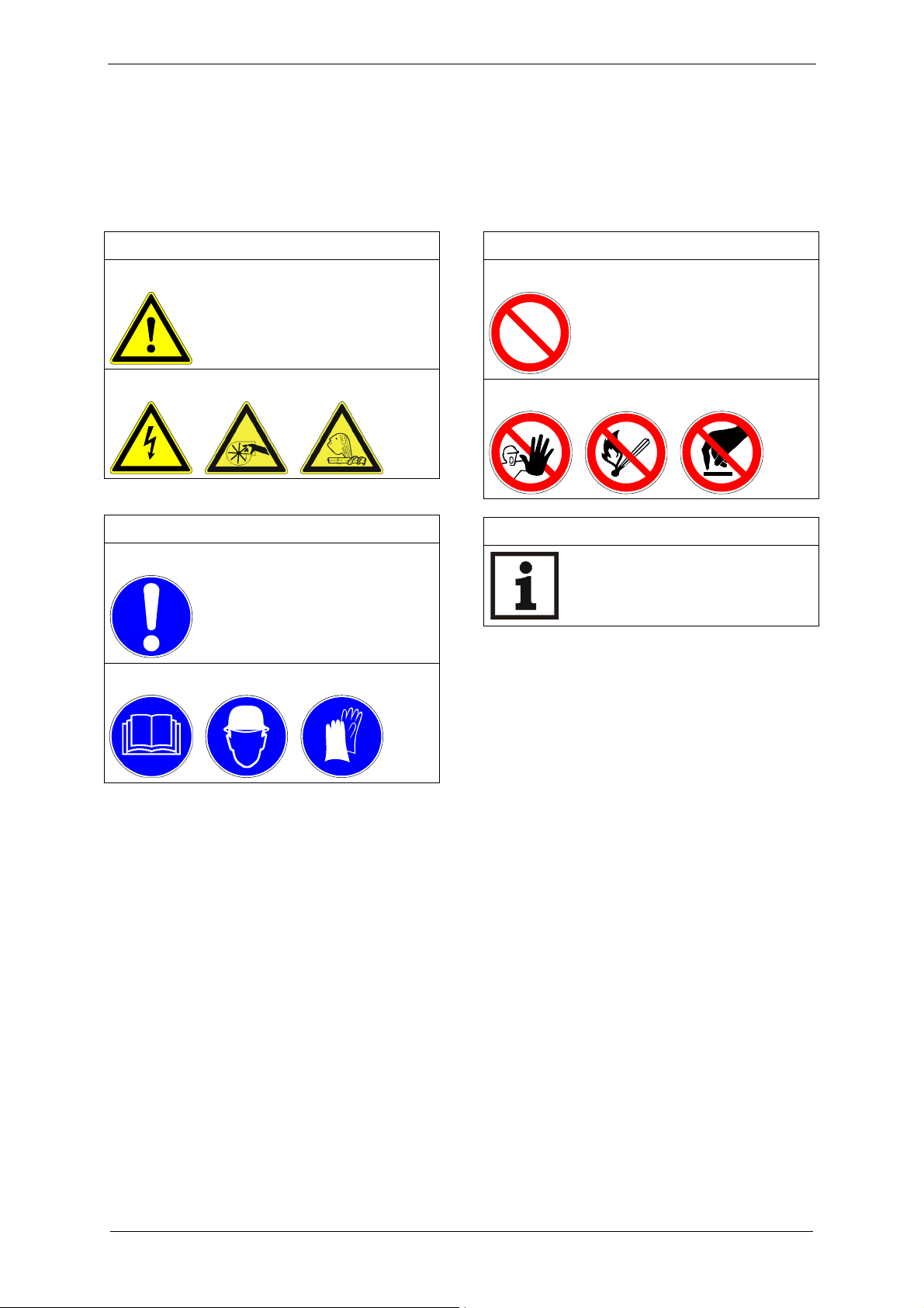
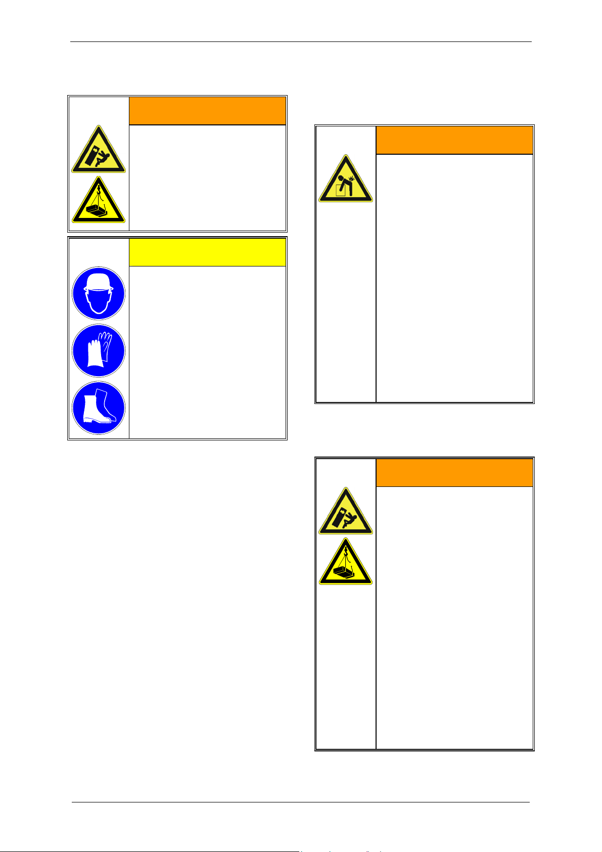
2.1.3 Graphic symbols
The graphic symbol is located in safety
precautions in the left-hand field.
There are several types of graphic symbols:
Hazard alerting symbols
Prohibition symbols
... for general dangers:
... for special dangers:
Mandatory action symbols
... for general instructions:
... for special instructions:
... for general prohibitions:
... for special prohibitions:
Information
610.48060.40.000 8 / 64 © Gardner Denver Deutschland GmbH
Page 9
2.2 General safety precautions
WARNING
Safety
WARNING
Improper use of the unit can
result in serious
or even fatal injuries!
These operating instructions
must have been read
completely and understood
before beginning any work
with or at the pump-motor
When working on the unit,
there is a danger of injury,
e.g. in the form of cuts/cutting
off, crushing and burns!
During transport/handling as well
as assembly and disassembly
always wear personal protective
equipment (safety helmet,
protective gloves, safety boots)!
unit,
must be strictly observed,
must be available at the
operating location of the
pump-motor unit.
WARNING
WARNING
Hair and clothing can be pulled
Improper use of the unit can
result in serious
or even fatal injuries!
Only operate the pump-motor
into the unit or caught and
wound up
moving parts!
Do not wear long, loose hair or
wide, loose clothes!
unit
for the purposes indicated
under "Intended Use"!
with the fluids indicated under
Use a hair net!
DANGER
'Intended Use'!
with the values indicated
under 'Technical Data'!
WARNING
Electrical danger!
Before beginning work on the
unit or system, the following
measures must be carried out:
Deenergize.
Improper use of the unit can
result in serious
or even fatal injuries!
Transport and handling as well
as assembly and disassembly of
the unit may be carried out by
trained and responsible
personnel only!
Secure against being
switched on again.
Determine whether
deenergized.
Ground and short-circuit.
Cover or block off adjacent
energized parts.
DANGER
Electrical danger!
Work on electrical installations
© Gardner Denver Deutschland GmbH 9 / 64 610.48060.40.000
may be carried out by trained
and authorized electricians only!
Page 10
Safety
DANGER
Electrical danger!
Do not open the motor terminal
box unless absence of electricity
has been ensured!
WARNING
Danger due to gauge pressure
and vacuum!
Danger due to escaping fluid!
Before beginning work on the
unit or system:
Interrupt supply of operating
liquid.
Bleed lines and vacuum
pump/compressor
(depressurize).
WARNING
Danger from rotating external
fan of unit!
Only operate the unit with the fan
guard mounted!
It is prohibited to remove the fan
guard!
WARNING
Danger from rotating impeller
WARNING
Danger due to gauge pressure
and vacuum!
Danger due to escaping fluid!
Only operate the unit with the
pipes/hoses connected to the
intake and discharge connection,
as well as to the operating-liquid
port!
WARNING
Danger from rotating impeller
of unit!
Only operate the unit with the
pipes/hoses connected to the
intake and discharge connection,
as well as to the operating-liquid
port!
WARNING
Danger in the form of cuts or
cutting off extremities on the
impeller of the pump-motor
unit!
Do not reach into the unit through
open connections!
Do not insert objects into the unit
through the openings!
WARNING
of unit!
Only operate the unit with the
vacuum pump/compressor
housing mounted!
Do not remove the vacuum
pump/compressor housing until
after the unit has been shut down
and the impeller has come to a
complete stop!
Consider that the impeller has a
certain run-out!
Danger due to gauge pressure
and vacuum!
Check the lines and containers
used for sufficient strength!
WARNING
Danger due to gauge pressure
and vacuum!
Danger due to escaping fluid!
Check the connections of the
pipe/hose connections for leaks!
610.48060.40.000 10 / 64 © Gardner Denver Deutschland GmbH
Page 11
Safety
WARNING
Danger of burns and scalding
from hot surfaces of the pumpmotor unit and from hot fluids!
Do not touch during operation!
Allow to cool after shut-down!
CAUTION
2.3 Residual risks
Danger zone:
Shaft exposed in gap between
drive motor and vacuum
A
pump/compressor.
Hazard:
WARNING
Possible entanglement of long,
Danger of unit tipping over!
Secure the pump-motor unit on
the installation surface before
putting into operation!
loose hair!
Protective measures:
Wear hair net!
WARNING
Danger zone:
Fan guard
Hazard:
Long, loose hair can be drawn
into external fan through fan
guard grate, even with fan guard
mounted!
Protective measures:
Wear hair net!
WARNING
Danger zone:
Hot surface.
Hazard:
Burns/scalding possible.
Protective measures:
Do not touch!
Wear protective gloves!
© Gardner Denver Deutschland GmbH 11 / 64 610.48060.40.000
Page 12

Intended Use
3 Intended Use
These operating instructions
apply to liquid-ring vacuum
pumps/compressors of the L-BV7 series,
types 2BV7 060, 2BV7 061, 2BV7 070 and
2BV7 071,
contains instructions bearing on transport
and handling, installation, commissioning,
operation, shut-down, storage, servicing
and disposal of the L-BV7,
must be completely read and understood by
all operating and servicing personnel before
beginning to work with or on the L-BV7,
must be strictly observed,
must be available at the site of operation of
the L-BV7.
About the operating and servicing personnel of
the L-BV7:
These persons must be trained and
authorized for the work to be carried out.
Work on electrical installations may be
carried out by trained and authorized
electricians only.
If necessary, the training/instruction on
using the L-BV7 can be carried out by the
manufacturer/suppler on order of the
owner.
The L-BV7
are pump-motor units for generating
vacuum or gauge pressure.
are used to extract, transport and compress
the following
pumped gases/vapors:
– all dry and humid gases,
which are not explosive or flammable,
– preferably air or air/vapor mixtures.
– In case of corrosive or toxic
gases/vapors contact service.
are designed for operation with the
following
operating liquids:
– Water
with a pH of 6 to 9,
free of solid materials (such as sand).
– If the pH values or operating liquids
differ, it is necessary to contact service.
are intended for industrial applications.
are designed for continuous operation.
When operating the L-BV7, the limits listed in
Chapter 4, "Technical Data", Pg. 13 ff. must
always be complied with.
Foreseeable Misuse
It is prohibited
to use the L-BV7 in applications other than
industrial applications
unless the necessary protection is provided
on the system,
e.g. guards suitable for children's fingers,
to use the device in rooms in which
explosive gases can occur if the L-BV7 is
not expressly intended for this purpose;
to extract, to deliver and to compress
explosive, flammable, corrosive or toxic
fluids
unless the L-BV7 is specifically designed
for this purpose,
to operate the L-BV7 with values other than
those specified in Chapter 4, "Technical
Data", Pg. 13 ff.
Any unauthorized modifications of the L-BV7
are prohibited for safety reasons.
any maintenance and repair work, such as
replacing worn or defective components, may
only be carried out by companies authorized
by the manufacturer (please contact service).
610.48060.40.000 12 / 64 © Gardner Denver Deutschland GmbH
Page 13
4 Technical Data
4.1 Mechanical data
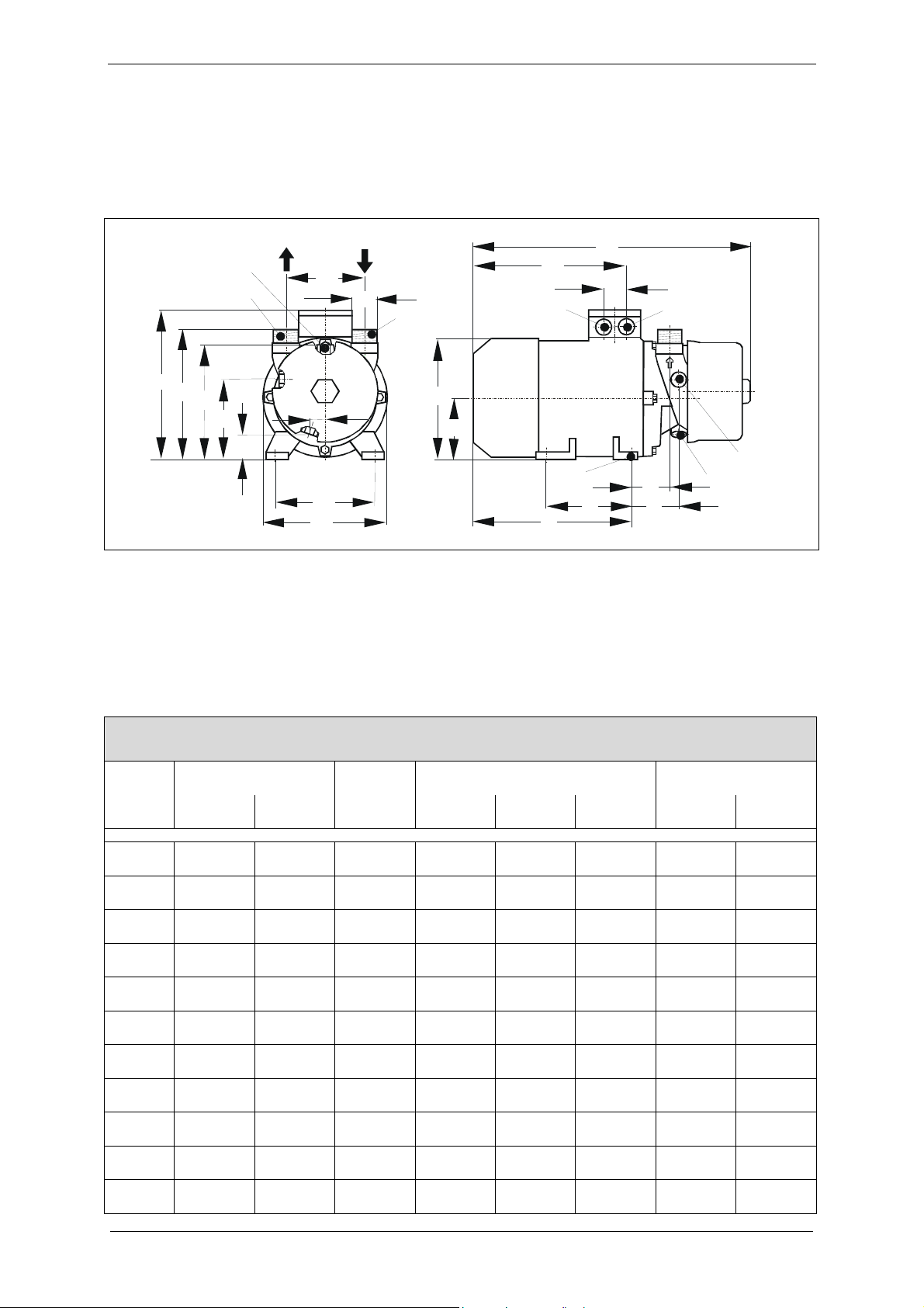
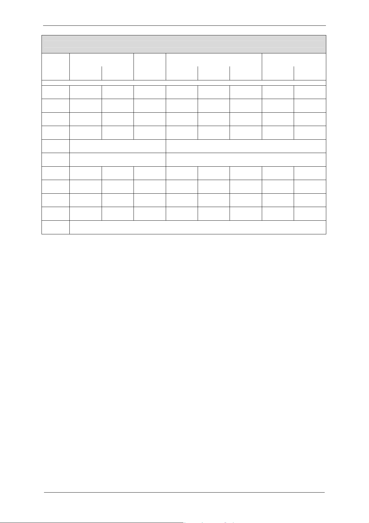
Dimensions
N3.0
N2.0
2
P
4
3
H
H
2
H
6
H
Fig. 1: Dimensions
N1.0 Inlet connection
N2.0 Discharge connection
N3.0 Operating-liquid port
N4.2 Emptying or drain opening
N8.7 Connection for cavitation protection
W1
d
W3
B1
B
N1.0
Technical Data
A
G
W
S
5
3
P
1
H
S4
N8.7
S
2
N4.2
R
E
L
M
Specification in mm
Type 2BV7 060 2BV7 061 2BV7 070 2BV7 071
...-1
...-2
...-3 ...-1 ...-2 ...-3 ...-1
...-2
...-3
A 335 372 394 438 473 482 488 511
B 162 180 180 202 204 266 227 266
B1 125 140 140 160 160 216 190 216
E 100 100 100 140 140 140 140 140
G 186 218 218 231 266 266 252 266
H1 80 90 90 100 100 132 112 132
H2 107 117 117 134 134 166 146 166
H3 156 166 166 194 194 227 206 227
H4 180 190 190 222 222 260 234 260
H6 26 36 36 34 34 66 46 66
L 184 225 225 249 284 284 263 284
© Gardner Denver Deutschland GmbH 13 / 64 610.48060.40.000
Page 14
Technical Data
Specification in mm
Type 2BV7 060 2BV7 061 2BV7 070 2BV7 071
...-1
...-2
...-3 ...-1 ...-2 ...-3 ...-1
...-2
...-3
M 72 68 68 89 89 99 96 99
P2 200 218 218 235 235 300 261 300
P3 161 180 180 201 202 265 225 265
R 59 55 55 71 71 81 78 81
S2 10 10 10 12 12 12 12 12
S4 M25 x 1.5 M32 x 1.5
S5 M16 x 1.5 M32 x 1.5
W 32 32 32 42 42 42 42 42
W1 110 110 110 120 120 120 120 120
W3 23 23 23 28 28 28 28 28
d G 1 G 1 G 1 G 1½ G 1½ G 1½ G 1½ G 1½
N3.0,
4.2, 8.7
G ¼
Specifications in inches
Type 2BV7 060 2BV7 061 2BV7 070 2BV7 071
...-1
...-2
...-3 ...-1 ...-2 ...-3 ...-1
...-2
...-3
A 13.2 14.6 15.5 17.2 18.6 19.0 19.2 20.1
B 6.38 7.09 7.09 7.95 8.03 10.5 8.94 10.5
B1 4.92 5.51 5.51 6.30 6.30 8.50 7.48 8.50
E 3.94 3.94 3.94 5.51 5.51 5.51 5.51 5.51
G 7.32 8.58 8.58 9.09 10.5 10.5 9.92 10.5
H1 3.15 3.54 3.54 3.94 3.94 5.20 4.41 5.20
H2 4.21 4.61 4.61 5.28 5.28 6.54 5.75 6.54
H3 6.14 6.54 6.54 7.64 7..4 8.94 8.11 8.94
H4 7.09 7.48 7.48 8.74 8.74 10.2 9.21 10.2
H6 1.02 1.42 1.42 1.34 1.34 2.60 1.81 2.60
L 7.24 8.86 8.86 9.80 11.2 11.2 10.4 11.2
M 2.83 2.68 2.68 3.50 3.50 3.90 3.78 3.90
610.48060.40.000 14 / 64 © Gardner Denver Deutschland GmbH
Page 15
Technical Data
Specifications in inches
Type 2BV7 060 2BV7 061 2BV7 070 2BV7 071
...-1
...-2
...-3 ...-1 ...-2 ...-3 ...-1
...-2
...-3
P2 7.87 8.58 8.58 9.25 9.25 11.8 10.3 11.8
P3 6.34 7.09 7.09 7.91 7.95 10.4 8.86 10.4
R 2.32 2.17 2.17 2.80 2.80 3.19 3.07 3.19
S2 0.394 0.394 0.394 0.472 0.472 0.472 0.472 0.472
S4 M25 x 1.5 M32 x 1.5
S5 M16 x 1.5 M32 x 1.5
W 1.26 1.26 1.26 1.65 1.65 1.65 1.65 1.65
W1 4.33 4.33 4.33 4.72 4.72 4.72 4.72 4.72
W3 0.906 0.906 0.906 1.10 1.10 1.10 1.10 1.10
d G 1 G 1 G 1 G 1½ G 1½ G 1½ G 1½ G 1½
N3.0,
4.2, 8.7
G ¼
© Gardner Denver Deutschland GmbH 15 / 64 610.48060.40.000
Page 16
Technical Data
Weight
4.3 Operating conditions
Type Weight
[kg] [lbs]
2BV7 060-1A.0. approx. 16 approx. 35.3
2BV7 060-2A.0. approx. 17 approx. 37.5
2BV7 060-3A.0. approx. 18 approx. 39.7
2BV7 061-1A.0. approx. 22 approx. 48.5
2BV7 070-1A.0. approx. 31 approx. 68.3
2BV7 070-2A.0. approx. 35 approx. 77.2
2BV7 070-3A.0. approx. 48 approx. 106
2BV7 071-1A.0. approx. 39 approx. 86
2BV7 071-2A.0. approx. 50 approx. 110
2BV7 071-3A.0. approx. 56 approx. 123
Minimum distances for heat dissipation
Temperatures
Temperature
of pumped
gases/vapors:
Operatingliquid
temperature:
temperature:
max. +80 °C [max. +176 °F]
At higher fluid temperatures,
measures must be taken on
the system to prevent burns,
e.g. mount separating safety
device (cover).
max. +80 °C [max. +176 °F]
min. +5 °C [min. +41 °F]
Nominal
value:
+15 °C
[+59 °F]
max. +40 °C [+104 °F] Ambient
min. +5 °C [+41 °F]
Type
2BV7 060 34 1.34
2BV7 061 34 1.34
2BV7 070 53 2.09
2BV7 071 53 2.09
Noise level
Measuring-surface sound pressure level as per
EN ISO 3744, measured at distance of 1 m
[3.28 ft] with medium throttling (100 mbar abs.
[1.45 psia]) and connected lines, tolerance 3
dB (A).
Type
2BV7 060 70
2BV7 061 70
2BV7 070 72
2BV7 071
Limit speeds for supply by converter
Type n [rpm]
2BV706 4,800
2BV707 4,000
4.2 Electrical data
See drive motor rating plate.
Minimum distance from
fan guard to adjacent surface
[mm] [inches]
1-m measuring-surface sound
pressure level L [dB (A)]
at 50 Hz: at 60 Hz:
70
76
Pressures
Min. inlet
pressure:
Dependent on the operating
liquid temperature
(see Fig. 2, Pg. 17)
When this temperature is
dropped below, the hose of
the liquid separator
(accessory) must be
connected to the connection
for cavitation protection
(Fig. 7, Pg. 25, Item 4).
Max.
1.1 bar abs. [16.0 psia]
discharge
pressure
during
vacuum-pump
operation:
8 bar abs. [116 psia] Max.
permissible
pressure in
pump-motor
unit:
If higher pressures can occur
in the system, then
corresponding protective
devices must be provided.
Max. discharge pressure p
compressor operation (at inlet pressure p
2 max
during
=
1
1 bar abs. [14.5 psia]):
p
Type
[bar abs.] [psia]
at
50 Hz:
2BV7 060 2 2 29.0 29.0
2BV7 061 2 2 29.0 29.0
2BV7 070 3 2.5 43.5 36.3
2BV7 071 3.5 2.5 50.8 36.3
at
60 Hz:
2 max
at
50 Hz:
at
60 Hz:
610.48060.40.000 16 / 64 © Gardner Denver Deutschland GmbH
Page 17
Technical Data
300
250
200
150
[mbar abs.]
1
p
100
50
0
0 20406080
fl[°C]
4.5
4
3.5
3
2.5
[psia]
2
1
p
1.5
1
0.5
0
0 50 100 150 200
[°F]
fl
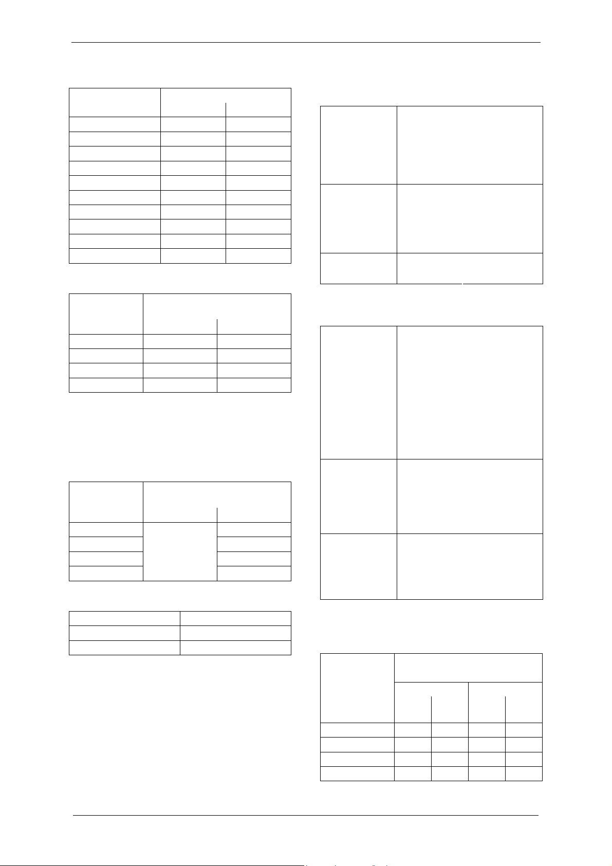
Fig. 2: Minimum inlet pressure/cavitation limit
fl [°C, °F] = Temperature of operating liquid
[mbar abs., psia] = Inlet pressure abs.
p
1
The minimum permissible inlet pressure of the pump-motor unit is dependent on the temperature of the operating
liquid.
During operation without cavitation protection, the minimum inlet pressure must be set above the shaded area.
Nominal operating-liquid flow rate
(with dry air extraction and with water at 15°C
[59 °F] as operating liquid)
Type
Flow rate
[m³/h] [ft³/h]
at
50 Hz:
at
60 Hz:
at
50 Hz:
at
60 Hz:
2BV7 060 0.20 0.20 7.06 7.06
2BV7 061 0.23 0.23 8.12 8.12
2BV7 070 0.28 0.34 9.89 12.0
2BV7 071 0.45 0.55 15.9 19.4
Operating-liquid filling amount for priming
Filling amount Type
[l] [gal (US)] [gal (UK)]
2BV7 060 0.40 0.106 0.088
2BV7 061 0.55 0.145 0.121
2BV7 070 0.80 0.211 0.176
2BV7 071 1.10 0.291 0.242
© Gardner Denver Deutschland GmbH 17 / 64 610.48060.40.000
Page 18
Description of Vacuum Pump/Compressor
5 Description of Vacuum Pump/Compressor
2
1
3
4
5
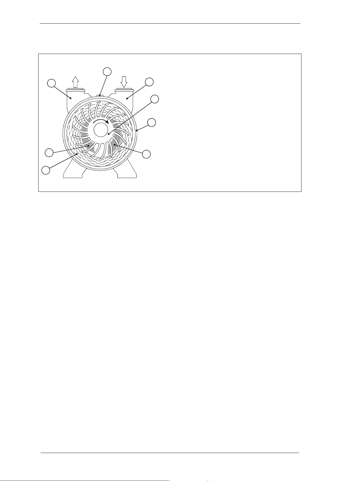
Fig. 3: Design and operation of liquid-ring
vacuum pumps/compressors (cross-section of
operating chamber)
1 Discharge connection
2 Operating-liquid port
3 Inlet connection
4 Impeller
5 Housing
6 Discharge port
7 Inlet port
8 Operating liquid
6
8
7
5.1 Design
The L-BV7 2BV7s are liquid-ring vacuum
pumps compressors. They consist of the
vacuum pump/the compressor itself and an
electric motor. For the detailed design, see
Fig. 3, Pg. 18.
The pumped gases/vapors are sucked via the
inlet connection (3) into the pump-motor unit
and pushed out via the discharge connection
(1).
The impeller (4) with the blades is located in
the cylindrical housing (5). The impeller is
arranged eccentrically relative to the housing.
In addition, the housing also contains the
operating liquid (8). This liquid is fed in via the
operating-liquid port (2) and output together
with the pumped gases/vapors via the
discharge connection (1).
5.2 Operating method
When the impeller turns, the operating liquid is
put into motion and accelerated. This forms a
liquid ring that also rotates. Due to centrifugal
force, this ring is arranged concentrically to the
housing and eccentrically to the impeller.
During a complete rotation of the impeller, the
following occurs:
The impeller cells are completely filled with
operating liquid at the upper vertex.
During the first half rotation, the liquid ring
lifts off the impeller hub. The space in the
cells increases so that the pumped
gases/vapors are sucked in through the
inlet port (7).
The space in the cells is largest at the lower
vertex, as these are virtually free of
operating liquid.
During the second half rotation, the liquid
ring approaches the hub again. The space
in the cells decreases so that the pumped
gases/vapors are compressed and pushed
out through the discharge port (6).
610.48060.40.000 18 / 64 © Gardner Denver Deutschland GmbH
Page 19
5.3 Operating modes
The pump-motor unit can function in several
different operating modes.
These differ in how the pump-motor unit is
supplied with operating liquid:
Self-priming operation
Operation with operating-liquid feed:
– Non-automatic operation
– Automatic operation
5.3.1 Self-priming operation
In this operating mode the pump-motor unit
automatically sucks in the operating liquid.
The operating-liquid flow rate is automatically
adjusted.
See Fig. 8, Pg. 30.
5.3.2 Operation with operating-liquid feed
In this operating mode the pump-motor unit
DOES NOT automatically suck in the operating
liquid.
A certain volume flow ("nominal operatingliquid flow rate") or pre-pressure must be set
for the operating liquid.
Description of Vacuum Pump/Compressor
Here the following additional distinctions are
made:
Non-automatic operation
In this case the operating liquid feed is
switched on and off manually with a stop valve.
See Fig. 11, Pg. 32.
Automatic operation
In this case the operating liquid feed is
switched on and off by a solenoid valve. The
solenoid valve is dependent on the motor
operating mode:
Motor/pump-motor unit switched on:
Valve open.
Motor/pump-motor unit switched off:
Valve closed.
See Fig. 12, Pg. 32.
NOTICE
The following is dependent on
the operating mode:
when and how the pump-
motor unit must be filled with
operating liquid the first time,
how the pump-motor unit is
put into operation.
The specifications for this are
contained in Chapter 7,
"Installation", Pg. 22ff., and
Chapter 8, "Commissioning",
Pg. 28ff.
© Gardner Denver Deutschland GmbH 19 / 64 610.48060.40.000
Page 20
Transport and Handling
6 Transport and Handling
WARNING
Danger from tipping or falling
loads!
Prior to transport and handling
make sure that all components
are securely assembled and
secure or remove all components
the fasteners of which have been
loosened!
CAUTION
Tipping or falling can lead to
crushing, broken bones etc.!
Sharp edges can cause cuts!
Wear personal safety equipment
(protective helmet, protective
gloves, safety shoes) during
transport!
Packing:
On delivery the pump-motor unit is bolted to a
pallet and covered with a cardboard box.
To unpack, remove the cardboard box and
unscrew the securing bolts on the feet of the
pump-motor unit.
Manual handling:
WARNING
Danger from lifting heavy
loads!
Manual handling of the unit is
only permitted within the
following limits:
max. 30 kg [max. 66 lbs]
for men
max. 10 kg [max. 22 lbs]
for women
max. 5 kg [max. 11 lbs]
for pregnant women
For the weight of the pump-motor
unit, see Chapter 4.1,
"Mechanical data",
Section "Weight", Pg. 16.
For weights above the given
values use suitable lifting
appliances and handling
equipment!
Handling by means of lifting equipment:
WARNING
Danger from tipping or falling
loads!
When transporting with lifting
equipment, observe the following
basic rules:
The lifting capacity of lifting
equipment and lifting gear
must be at least equal to the
unit's weight.
For the weight of the pumpmotor unit, see Chapter 4.1,
"Mechanical data",
Section "Weight", Pg. 16.
The pump-motor unit must be
secured so that it cannot tip or
fall.
Do not stand or walk under
suspended loads!
610.48060.40.000 20 / 64 © Gardner Denver Deutschland GmbH
Page 21

Transport and handling by means of a crane
and strap belts is advisable.
Transport and Handling
Attach the strap belts as shown in Fig. 4,
Pg. 21:
Use two strap belts, of which one is routed
under the vacuum pump/compressor
housing, and one under the fan guard.
The strap belts should be seated securely
in the undercuts so that the unit cannot slip
out.
The belts must be sufficiently long (spread
angle smaller than 90°).
Make sure that no damage is caused to any
attached fittings.
WARNING
Danger from tipping loads!
Be sure to observe the routing of
the strap belts as shown in
Fig. 4, S. 21, even if the motor is
provided with attachment points
such as transport eyes or eye
bolts.
Fig. 4: Attachment points
These are solely designed for the
separate transport of the motor,
however not for the different
weight distribution that results for
the mounted vacuum
pump/mounted compressor, so
that the unit could tip!
© Gardner Denver Deutschland GmbH 21 / 64 610.48060.40.000
Page 22

Installation
7 Installation
7.1 Installation
CAUTION
CAUTION
Danger of crushing from unit
tipping over!
In the unmounted state, the unit
can easily tip due to its weight
distribution!
Wear gloves and safety shoes!
Handle the unit with the
appropriate care!
CAUTION
Danger of damage to the
pump-motor unit due to
overheating!
When installing the unit, make
sure that heat dissipation and
cooling are not obstructed. The
minimum distances specified in
Chapter 4.1, "Mechanical data",
Section "Minimum distances for
heat dissipation", Pg. 16 must be
complied with.
Discharge air of other units may
Danger of tripping and falling!
Make sure the unit does not
present a danger of tripping!
WARNING
For the space requirement and arrangement of
the holes for installing and securing the pumpmotor unit, please see Fig. 1, Pg. 13.
For minimum clearances for heat dissipation
not be directly sucked in again!
and cooling, see Chapter 4.1, "Mechanical
Electrical danger!
The pump-motor unit must be
installed so that the electrical
device cannot be damaged by
external influences!
data", Section "Minimum distances for heat
dissipation", Pg. 16.
The pump-motor unit must be installed as
follows:
In particular, the feed pipes must
be securely routed, e.g. in cable
ducts or in the floor.
CAUTION
Danger of injuries from flying
parts!
Select installation so that parts
that are thrown out through the
grate if the external fan breaks
cannot hit persons!
on level surfaces,
with shaft in horizontal position,
on stationary (fixed) surfaces or structures,
at a maximum height of 1000 m [3280 ft]
above sea level.
Observe the following when installing the
pump-motor unit:
The load bearing capacity of the base
plate or the foundation must be designed
for at least the weight of the unit.
The vibration behavior at the operating
location must be taken into account.
The total vibrations of the unit are
dependent on the following factors:
– the characteristic vibrations of the unit,
– the alignment and installation,
– the condition (vibration behavior) of the
load-bearing surface,
– the influences by vibrations of other
parts and system components (external
vibrations).
The maximum permissible value for
vibrations is v
= 4.5 mm/s.
eff
To ensure proper operation and a long
610.48060.40.000 22 / 64 © Gardner Denver Deutschland GmbH
Page 23

service life of the unit, this value may not be
exceeded.
Generally, this value can be adhered to
without a special foundation or a special
base plate.
The points on the unit for measuring the
vibration speed are shown in Fig. 5, Pg. 23.
Installation
Bolt the feet of the unit to the supporting
surface with suitable securing elements, as
shown in Fig. 6, Pg. 23.
Fig. 5: Points for measuring the vibration
speed
Different installation, e.g. with the shaft in the
vertical position, requires consultation with
service.
Fig. 6: Securing elements for bolting feet to
supporting surface
2BV7 06: M = 4 x M8-6.8
2BV7 07: M = 4 x M10-6.8
© Gardner Denver Deutschland GmbH 23 / 64 610.48060.40.000
Page 24

Installation
7.2 Electrical connection (motor)
The electrical connection must be carried out
as follows:
according to the applicable national and
local laws and regulations,
according to the applicable system-
dependent prescriptions and requirements,
according to the applicable regulations of
the utility company.
DANGER
Electrical danger!
Malpractice can result in severe
injuries and material damage!
DANGER
Electrical danger!
The electrical connection may be
carried out by trained and
authorized electricians only!
DANGER
Electrical danger!
Before beginning work on the
unit or system, the following
measures must be carried out:
Deenergize.
Secure against being
switched on again.
Determine whether
deenergized.
Ground and short-circuit.
Cover or block off adjacent
energized parts.
WARNING
Danger due to gauge pressure
and vacuum!
Danger due to escaping fluid!
Before beginning work on the
unit or system:
Interrupt supply of operating
liquid.
Bleed lines and vacuum
pump/compressor
(depressurize).
CAUTION
Incorrect connection of the motor
can lead to serious damage to
the unit!
Observe the motor rating plate.
It is imperative that the operating conditions
correspond to the data given on the rating
plate!
Deviations permissible without reduction in
performance:
±5 % voltage deviation
±2 % frequency deviation
Make the connection in accordance with the
circuit diagram in the terminal box.
Connect the protective conductor.
Use suitable cable lugs when doing so.
The electrical connection must be
permanently safe.
Tightening torques for terminal plate
connections:
Thread
Tightening
torque
[Nm]
[ft lbs]
M4 M5
0.8 ... 1.2 1.8 ... 2.5
0.590 ...
0.885
1.33 ...
1.84
WARNING
Electrical danger!
Clearance between bare live
parts and between bare live parts
and ground:
at least 5.5 mm [0.217"] (at a
nominal voltage of V
≤ 690V)
n
Make sure there are no
protruding pieces of wire!
610.48060.40.000 24 / 64 © Gardner Denver Deutschland GmbH
Page 25

Installation
WARNING
7.3 Connecting pipes/hoses (vacuum
pump/compressor)
Electrical danger!
The terminal box must be free
from
foreign bodies,
dirt,
humidity.
Terminal box cover and cable
entries must be tightly closed so
as to make them dustproof and
waterproof.
Check for tightness at regular
intervals.
For motor overload protection:
Use motor circuit breakers.
Set the motor circuit breakers to the
nominal current specified on the rating
plate.
For supply by converter:
High-frequency current and voltage
harmonics in the motor supply cables can
lead to emitted electromagnetic
interference.
Use shielded supply cables,
whereby the shield must be installed on
both sides.
Limit speed:
see Chapter 4.2, "Electrical data", Pg. 16.
CAUTION
If the unit is run dry, the
mechanical seal will be
destroyed in a matter of seconds!
DO NOT switch on as long as the
unit is not filled with operating
liquid!
Fig. 7: Pipe/hose connection of vacuum
pump/compressor
1 Operating-liquid port G ¼"
2 Discharge connection
3 Inlet connection
4 Connection for cavitation protection G ¼"
5 Drain opening G ¼"
To prevent foreign bodies from entering the
unit, all connections are sealed off when
delivered.
Do not remove the sealing plugs until
immediately before connecting the
pipes/hoses.
For the arrangement of the pipe/hose
connection, see Fig. 7, Pg. 25.
The pumped gases/vapors are sucked in via
the inlet connection
(see Chapter 7.3.1,
Pg. 26) and discharged via the discharge
connection (see Chapter 7.3.2, Pg. 26).
For operation the unit must be continuously
supplied with operating liquid.
This is fed in via the operating-liquid port
(see
Chapter 7.3.3, Pg. 26) and discharged
together with the pumped gases/vapors
through the discharge connection
.
© Gardner Denver Deutschland GmbH 25 / 64 610.48060.40.000
Page 26

Installation
Fill with operating liquid:
7.3.1 Inlet connection
When and how the pump-motor unit must be
filled with operating liquid the first time is
dependent on the operating mode:
For self-priming operation:
During installation.
For operation with operating-liquid feed:
After completing installation.
For self-priming operation you now pour
operating liquid into the working space of the
pump-motor unit before you connect the
pipes/hoses to the unit.
To do this, pour operating liquid into the open
inlet connection, discharge connection or
operating-liquid port.
For proper filling quantities, see Chapter 4.3,
"Operating conditions", Section "Operatingliquid filling amount for priming", Pg. 17.
Then attach the pipes/hoses to the unit as
described in the following.
WARNING
Danger due to gauge pressure
and vacuum!
Danger due to escaping fluid!
During operation, connected
pipes and vessels are
pressurized or vacuumized!
Make sure that all connections
are sufficiently tight! Use only
pipes and vessels of sufficient
strength!
NOTICE
Attach pipes/hoses free of
mechanical tensions.
The inlet connection (Fig. 7, Pg. 25, Item 3) is
marked with an arrow pointing downward (↓).
Connect the inlet pipe here. The pumped
gases/vapors are sucked in via this.
CAUTION
The tightening torque for pipe
connections on intake and
discharge connections may not
exceed 100 Nm [73.8 ft lbs]!
7.3.2 Discharge connection
The discharge connection (Fig. 7, Pg. 25,
Item 2) is marked with an arrow pointing
upward (↑).
Connect the discharge pipe here. Both the
pumped gases/vapors and the operating liquid
are discharged via this pipe.
CAUTION
The tightening torque for pipe
connections on intake and
discharge connections may not
exceed 100 Nm [73.8 ft lbs]!
7.3.3 Operating-liquid port
The operating-liquid port (Fig. 7, Pg. 25,
Item 1) is located between the discharge and
inlet connection.
Connect the feed pipe for the operating liquid
here.
Support the weight of the
pipes/hoses.
610.48060.40.000 26 / 64 © Gardner Denver Deutschland GmbH
Page 27

7.3.4 Notes
Installation
For operating liquid with
impurities:
Install a filter, screen or
separator in the supply line if
necessary.
In case of operating liquid with
a high lime content:
Soften operating liquid
OR
Decalcify pump-motor unit
regularly (see Chapter 11.1,
"Maintenance", Pg. 36).
To prevent installation residues
(e.g. welding spatter) from
entering the unit,
a start-up screen should be
installed in the inlet pipe for the
first 100 operating hours.
7.4 Accessories
NOTICE
NOTICE
NOTICE
The following accessories are available
according to our catalogue:
Liquid separator
Non-return valve
Connecting and counter flange
Gas ejector.
See Chapter 13, "Accessories", Pg. 44.
© Gardner Denver Deutschland GmbH 27 / 64 610.48060.40.000
Page 28

Commissioning
8 Commissioning
WARNING
Danger due to gauge pressure
and vacuum!
Danger due to escaping fluid!
Danger due to rotating parts!
The pump-motor unit may only
be put into operation when the
following conditions are met:
Fan guard and vacuum
pump/compressor housing
8.1 Preparation and start-up
CAUTION
If the pumped gases/vapors
discharged on the pressure side
are passed on,
then it must be ensured that the
maximum discharge pressure of
1.1 bar abs. [16.0 psia] is not
exceeded!
NOTICE
are mounted.
The lines to the discharge
connection, inlet connection
and operating-liquid port are
attached.
The lines and connections
have been tested for strength
and leaks.
CAUTION
If a shut-off device is installed in the discharge
pipe:
Make sure that the unit CANNOT be operated
Maximum permissible quantity of
water entrained via the inlet
connection:
See Fig. 13, Pg. 32.
with the shut-off device closed.
If the unit is run dry, the
mechanical seal will be
destroyed in a matter of seconds!
DO NOT switch on as long as the
unit is not filled with operating
liquid!
Fill with operating liquid:
When and how the pump-motor unit must be
filled with operating liquid the first time is
dependent on the operating mode:
For self-priming operation:
During installation.
For operation with operating-liquid feed:
After completing installation.
For operation with operating-liquid feed,
you now fill the working area of the unit with
operating liquid.
To do this, open the respective stop valve for
approx. 20 sec.:
For non-automatic operation:
Stop valve (Fig. 11, Pg. 32, Item 4).
For automatic operation:
Stop valve in the bypass pipe (Fig. 12,
Pg. 32, Item 4a).
Then proceed with commissioning as
described in the following.
610.48060.40.000 28 / 64 © Gardner Denver Deutschland GmbH
Page 29

Check connections of the pipes/hoses for
leaks.
Check direction of rotation:
The direction of flow of the pumped
gases/vapors is marked with arrows on the
intake and discharge connection.
The intended direction of shaft rotation is
marked with an arrow on the motor
mounting adapter between the intake and
discharge connection, as well as with an
arrow on the fan guard.
The pump-motor unit may not be allowed to
run dry!
Have you filled it with operating liquid
beforehand (during or after installation)?
See sections "Fill with operating liquid",
Pg. 26 and Pg. 28.
Briefly switch on pump-motor unit.
Compare the actual direction of rotation of
the external fan with the intended direction
of shaft rotation as indicated with the
arrows.
Switch off pump-motor unit again.
If necessary, reverse the direction of
rotation of the motor.
DANGER
Commissioning
WARNING
Danger due to gauge pressure
and vacuum!
Danger due to escaping fluid!
Before beginning work on the
unit or system:
Interrupt supply of operating
liquid.
Bleed lines and vacuum
pump/compressor
(depressurize).
The further procedure is again dependent
on the unit operating mode:
Electrical danger!
The electrical connection may be
carried out by trained and
authorized electricians only!
DANGER
Electrical danger!
Before beginning work on the
unit or system, the following
measures must be carried out:
Deenergize.
Secure against being
switched on again.
Determine whether
deenergized.
Ground and short-circuit.
Cover or block off adjacent
energized parts.
© Gardner Denver Deutschland GmbH 29 / 64 610.48060.40.000
Page 30

Commissioning
8.2 Self-priming operation
See Fig. 8, Pg. 30.
Here the following must be watched:
Starting the pump-motor unit:
The pump-motor unit must be pre-throttled
on the inlet side. This means a vacuum of
at least 900 mbar abs. [13.1 psia] must be
present in the inlet pipe (Item B) at switchon.
During switch-on, the liquid level in the feed
pipe (Item A) and in the reservoir (Item C)
respectively must be at the same level as
the center of the unit shaft (Item 1).
During operation the liquid level in the
reservoir (Item C) may not drop below
approx. 1 m [3.28 ft] below the center of
the unit shaft (Item 1).
1 m
3.28 ft
A B
1
2
Switch on the unit.
The operating liquid is sucked in.
900 mbar abs
13.1 psia
C
Fig. 8: Self-priming operation
A Feed pipe for operating liquid
B Inlet pipe
C Reservoir for operating liquid
1 Required liquid level when switching on
2 Min. liquid level during operation
610.48060.40.000 30 / 64 © Gardner Denver Deutschland GmbH
Page 31

8.3 Operation with operating-liquid feed
A
A
See Fig. 9, Pg. 31; and Fig. 10, Pg. 31, as well as Fig. 11, Pg. 32 and Fig. 12, Pg. 32.
Proceed as follows here:
Method A:
Method B:
Commissioning
1) Set pre-pressure of operating liquid (Fig. 9,
Pg. 31):
Set a pre-pressure p
in the feed pipe for
A
the operating liquid (Item A) around
approx. 1 bar [14.5 psi] above the inlet
pressure p
in the inlet pipe (Item B).
B
2) Start up the unit:
For non-automatic operation (Fig. 11, Pg. 32):
Open the stop valve (Item 4) manually.
The operating liquid is fed in.
Switch on the unit.
For automatic operation (Fig. 12, Pg. 32):
Switch on the unit.
The solenoid valve (Item 4) opens
and the operating liquid is fed in.
p = p + 1 bar
AB
p = p + 14.5 psi
AB
1) Start up the unit:
For non-automatic operation (Fig. 11, Pg. 32):
Open the stop valve (Item 4) manually.
The operating liquid is fed in.
Switch on the unit.
For automatic operation (Fig. 12, Pg. 32):
Switch on the unit.
The solenoid valve (Item 4) opens
and the operating liquid is fed in.
2) Check the operating-liquid flow rate:
with the flow meter (Fig. 11, Pg. 32, and
Fig. 12, Pg. 32, Item 2)
OR
by measuring the volume of operating liquid
per unit of time that exits at the discharge
connection with a graduated vessel
(Fig. 10, Pg. 31)
3) Set/correct the operating-liquid flow rate:
via the control valve (Fig. 11, Pg. 32, and
Fig. 12, Pg. 32, Item 3)
Nominal operating-liquid flow rate:
For nominal values, see Chapter 4.3,
"Operating conditions", Section "Nominal
operating-liquid flow rate", Pg. 17.
B
B
Fig. 9: Setting the operating-liquid flow rate:
Setting pre-pressure
A Feed pipe for operating liquid
B Inlet pipe
Fig. 10: Setting the operating-liquid flow rate:
Measuring the volume with a graduated vessel
A Feed pipe for operating liquid
B Drain pipe for operating liquid
© Gardner Denver Deutschland GmbH 31 / 64 610.48060.40.000
Page 32

Commissioning
1
32
4
5
6
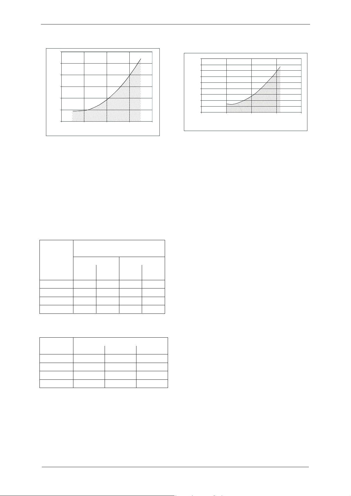
Fig. 11: Operation with operating-liquid feed: Non-automatic operation
1 Pump-motor unit
2 Flow meter
3 Control valve
1
4 Stop valve
5 Filter
6 Feed pipe for operating liquid
2 3 44a5 6
Fig. 12: Operation with operating-liquid feed: Automatic operation
1 Pump-motor unit
2 Flow meter
3 Control valve
4a Bypass with stop valve (for priming)
5 Filter
6 Feed pipe for operating liquid
4 Solenoid valve, connected to motor
4x
8x
3x
7x
t =
t = 2 s
A
B
Fig. 13: Maximum permissible quantity of water entrained via the inlet connection
A During continuous operation: 3x quantity of operating-liquid flow rate
B Briefly (up to 2 sec.): 7x quantity of operating-liquid flow rate
610.48060.40.000 32 / 64 © Gardner Denver Deutschland GmbH
Page 33

9 Operation
Operation
WARNING
Danger due to gauge pressure
and vacuum!
Danger due to escaping fluid!
Danger due to rotating parts!
The pump-motor unit may only
be put into operation when the
following conditions are met:
Fan guard and vacuum
pump/compressor housing
are mounted.
The lines to the discharge
connection, inlet connection
and operating-liquid port are
attached.
The lines and connections
have been tested for strength
and leaks.
CAUTION
9.1 Self-priming operation
Follow the instructions contained in
Chapter 8.2, "Self-priming operation", Pg. 30
for this operating mode.
9.2 Operation with operating-liquid feed
Start-up
For non-automatic operation (Fig. 11, Pg. 32):
Open the stop valve (Item 4) manually.
The operating liquid is fed in.
Switch on the unit.
For automatic operation (Fig. 12, Pg. 32):
Switch on the unit.
The solenoid valve (Item 4) opens
and the operating liquid is fed in.
Shut down:
For non-automatic operation (Fig. 11, Pg. 32):
If the unit is run dry, the
mechanical seal will be
destroyed in a matter of seconds!
DO NOT switch on as long as the
unit is not filled with operating
liquid!
WARNING
Danger of burns and scalding
from hot surfaces of the pumpmotor unit and from hot fluids!
Do not touch during operation!
Allow to cool after shut-down!
NOTICE
Switch off the pump-motor unit.
Close the stop valve (Item 4) manually.
Feeding of the operating liquid is cut off.
The following applies for the control valve
(Item 3) for setting the operating-liquid flow
rate:
In case of an interruption in operation, the
valve setting (i.e. the valve position or the
open valve cross-section) is not changed.
For automatic operation (Fig. 12, Pg. 32):
Switch off the pump-motor unit.
The solenoid valve (Item 4) closes,
and feeding of the operating liquid is cut off.
The following applies for the control valve
(Item 3) for setting the operating-liquid flow
rate:
In case of an interruption in operation, the
Maximum permissible quantity of
water entrained via the inlet
connection:
See Fig. 13, Pg. 32.
valve setting (i.e. the valve position or the
open valve cross-section) is not changed.
© Gardner Denver Deutschland GmbH 33 / 64 610.48060.40.000
Page 34

Shut-Down and Longer Standstills
10 Shut-Down and Longer Standstills
10.1 Draining
DANGER
Electrical danger!
Before beginning work on the
unit or system, the following
measures must be carried out:
Deenergize.
Secure against being
switched on again.
Determine whether
deenergized.
Ground and short-circuit.
Cover or block off adjacent
energized parts.
WARNING
Danger due to gauge pressure
and vacuum!
Danger due to escaping fluid!
Before beginning work on the
unit or system:
Interrupt supply of operating
liquid.
Bleed lines and vacuum
pump/compressor
(depressurize).
Switch off the pump-motor unit.
The above safety precautions apply when
working on the unit or system.
Provide suitable catch containers below the
vacuum pump/compressor housing.
Open the screw plug (Fig. 7, Pg. 25,
Item 5).
Allow the liquid to drain out.
Close the screw plug again,
tightening torque T
= 2 ... 3 Nm
t
[1.48 ... 2.21 ft lbs].
10.2 Preparing for longer standstill
Before a longer standstill (from approx.
4 weeks) or when there is danger of frost,
proceed as follows:
Drain pump-motor unit as described in
Chapter 10.1, "Draining", Pg. 34.
Remove the pipe/hose from the intake or
discharge connection.
Pour ½ l [0.132 gal (US); 0.110 gal (UK)] of
preservative (rust protection oil, e.g.
Mobilarma 247 form Mobil Oil)
into the open intake or discharge
connection.
Close the intake and discharge connection,
as well as the operating-liquid port and
remount the disconnected pipes/hoses.
Guide a M6 or M8 bolt (depending on the
type) with a sufficient shank length through
the center opening into the fan guard and
screw into the shaft end on the external fan
side (see Fig. 14, Pg. 34).
Turn the shaft by hand using the bolt.
Remove the M6 or M8 bolt again.
You have two options for the standstill:
Either the pump-motor unit remains
connected in the system,
or the unit is removed for storage.
Fig. 14: Pour in preservative and turn shaft
610.48060.40.000 34 / 64 © Gardner Denver Deutschland GmbH
Page 35

10.3 Storage conditions
This chapter applies in the following cases:
new pump-motor units,
pump-motor unit that are already installed
in a system and were prepared for a longer
standstill, as described in Chapter 10.2,
"Preparing for longer standstill", Pg. 34.
To prevent standstill damage during storage,
the environment must provide the following
conditions:
dry,
dust-free,
low-vibration (effective value of vibration
speed v
≤ 0.2 mm/s [0.008"/sec]).
eff
Take the following measures for
commissioning following a longer
standstill:
Measure the insulation resistance of the
motor.
In case of values ≤ 1kΩ per volt of nominal
voltage, dry winding.
Drain off preservative, as described in
Chapter 10.1, "Draining", Pg. 34.
Subsequent cleaning of the pump-motor
unit is not required.
Dispose of preservative in accordance with
the manufacturer's specifications.
For new pump-motor units:
Install pump-motor unit as described in
Chapter 7, "Installation", Pg. 22.
Commission the pump-motor unit as
described in Chapter 8, "Commissioning",
Pg. 28.
For pump-motor unit that are already
installed in a system:
Commission the pump-motor unit as
described in Chapter 8, "Commissioning",
Pg. 28.
Shut-Down and Longer Standstills
DANGER
Electrical danger!
Work on electrical installations
may be carried out by trained
and authorized electricians only!
© Gardner Denver Deutschland GmbH 35 / 64 610.48060.40.000
Page 36

Servicing
11 Servicing
DANGER
Electrical danger!
Before beginning work on the
unit or system, the following
measures must be carried out:
Deenergize.
Secure against being
switched on again.
Determine whether
deenergized.
Ground and short-circuit.
Cover or block off adjacent
energized parts.
WARNING
WARNING
Danger of burns and scalding
from hot surfaces of the pumpmotor unit and from hot fluids!
Do not touch during operation!
Allow to cool after shut-down!
WARNING
When working on the unit,
there is a danger of injury,
e.g. in the form of cuts/cutting
off, crushing and burns!
During transport/handling as well
as assembly and disassembly
always wear personal protective
Danger due to gauge pressure
and vacuum!
Danger due to escaping fluid!
equipment (safety helmet,
protective gloves, safety boots)!
Before beginning work on the
unit or system:
Interrupt supply of operating
liquid.
Bleed lines and vacuum
pump/compressor
(depressurize).
WARNING
Danger from rotating external
fan of unit!
It is prohibited to remove the fan
guard!
11.1 Maintenance
The pump-motor unit is largely maintenancefree.
However, if dirt or solid matter (e.g. sand) or
lime deposits get into the unit through the
operating liquid and/or the pumped
gases/vapors, then it is necessary to clean the
unit at regular intervals to prevent the impeller
from jamming up and to avoid wearing of the
impeller and the vacuum pump/compressor
housing.
WARNING
Refer to the following table:
Danger from rotating impeller
of unit!
Do not remove the vacuum
pump/compressor housing until
after the unit has been shut down
and the impeller has come to a
complete stop!
Consider that the impeller has a
certain run-out!
610.48060.40.000 36 / 64 © Gardner Denver Deutschland GmbH
Page 37

Contamination/Problem Remedy
Servicing
Dirt collects in the motor
cooling fins.
Fine-grain dirt (e.g. sand) get
into the vacuum
pump/compressor with the
operating liquid or pumped
gases/vapors.
Impeller is jammed.
Clean the motor cooling fins at regular intervals.
Install a liquid separator, filter or screen in the feed pipe.
OR
Regularly dismantle and clean the vacuum pump/compressor housing as
follows:
Shut unit down.
Drain the pump-motor unit as described in Chapter 10.1, "Draining",
Pg. 34.
Unscrew the housing with a 36 mm [
3
/8"] wrench (in direction of arrow
shown on housing) (see Fig. 15, Pg. 38).
Remove the housing.
Dirt has collected in the housing. Rinse out the housing.
Screw on the housing again (opposite direction of arrow shown on
housing) and tighten with a tightening torque of 50 Nm [36.9 ft lbs].
When commissioning the pump-motor unit, proceed as described in
Chapter 8, "Commissioning", Pg. 28.
Shut unit down.
Guide a M6 or M8 bolt (depending on the type) with a sufficient shank
length through the center opening into the fan guard and screw into the
shaft end on the external fan side (see Fig. 16, Pg. 38).
Free the shaft using the bolt.
Remove the bolt again.
Extremely hard water used
as operating liquid
Lime content > 15°dH).
Soften operating liquid.
OR
Decalcify the pump-motor unit at intervals of 3 months as follows (also see
Fig. 16, Pg. 38):
Wear personal protective equipment (protective gloves and safety
goggles),
Shut unit down.
Drain the pump-motor unit as described in Chapter 10.1, "Draining",
Pg. 34.
Remove pipes/hoses.
Fill the unit with decalcifying liquid through one of the connection
openings. Use 10% solution of acetic acid or another commercially
available decalcifying agent.
Allow the decalcifying liquid to soak for at least 30 minutes.
Turn the shaft occasionally during this time. To do this, guide a M6 or M8
bolt (depending on the type) with a sufficient shank length through the
center opening into the fan guard and screw into the shaft end on the
external fan side (see Fig. 16, Pg. 38).
Turn the shaft using the bolt.
Remove the bolt again.
Drain the decalcifying liquid out of the unit. To do this, proceed as
described in Chapter 10.1, "Draining", Pg. 34.
Mount pipes/hoses.
When commissioning the pump-motor unit, proceed as described in
Chapter 8, "Commissioning", Pg. 28.
The decalcifying liquid can be disposed of in the sewer system.
© Gardner Denver Deutschland GmbH 37 / 64 610.48060.40.000
Page 38

Servicing
Contamination/Problem Remedy
Dirt gets into the air
passages (fan guard,
external fan, cooling fins) of
the motor.
1
Clean the motor air passages regularly. To do so, proceed as follows:
Carry out protective measures for the use of compressed air:
Wear personal protective equipment (protective gloves and safety
goggles),
secure surroundings. Remove objects lying around.
Blow in compressed air through the fan guard grate.
It is prohibited to remove the fan guard!
2
Fig. 15: Removing vacuum pump/compressor housing
Carry out with 36 mm [3/8"] open-end wrench.
Fig. 16: Pouring in decalcifying agent and freeing shaft by turning
610.48060.40.000 38 / 64 © Gardner Denver Deutschland GmbH
Page 39

Servicing
11.2 Repairs/troubleshooting
Fault Cause Remedy Carried out by
Motor does
not start,
no motor
noise.
Motor does
not start,
humming
noise..
At least two
power supply
leads interrupted.
One power
supply lead
interrupted.
Impeller is
jammed.
Impeller
defective.
Motor bearings
defective.
Check fuses, terminals and cables for open
Electrician
circuit. Eliminate open circuit.
Check fuses, terminals and cables for open
Electrician
circuit. Eliminate open circuit.
Free shaft by turning.
Operator
See Chapter 11.1, "Maintenance", Pg. 36.
Decalcify vacuum pump/compressor.
Operator
See Chapter 11.1, "Maintenance", Pg. 36.
Drain and clean vacuum pump/compressor if
Operator
necessary.
See Chapter 11.1, "Maintenance", Pg. 36.
Check and correct impeller gap setting if
Service
necessary.
Replace impeller. Service
Replace motor bearings. Service
Protective
motor switch
trips when
motor is
switched on.
consumption
too high.
Unit does not
generate
vacuum.
Winding shortcircuit.
Motor
overloaded.
Counter-pressure
at discharge
connection too
high.
Share of liquid
also fed too high.
Impeller is
jammed.
Lime or other
deposits.
No operating
liquid.
Have winding checked. Electrician
Throttle operating-liquid flow rate.
Operator
See Chapter 8.2, "Self-priming operation", Pg. 30
or 8.3, "Operation with operating-liquid feed",
Pg. 31.
Reduce counter-pressure. Operator
Reduce share of liquid also fed. Operator
See "Motor does not start,
Service
humming noise."
Decalcify vacuum pump/compressor.
Operator Power
See Chapter 11.1, "Maintenance", Pg. 36.
Clean vacuum pump/compressor.
Operator
See Chapter 11.1, "Maintenance", Pg. 36.
Ensure proper operating-liquid flow rate.
Operator
See Chapter 8.2, "Self-priming operation", Pg. 30
or Chapter 8.3, "Operation with operating-liquid
feed", Pg. 31.
Severe leak in the
Seal leak in the system. Operator
system.
Wrong direction
of rotation.
© Gardner Denver Deutschland GmbH 39 / 64 610.48060.40.000
Reverse direction of rotation by interchanging two
connecting leads.
Electrician
Page 40

Servicing
Fault Cause Remedy Carried out by
Unit
generates
insufficient
vacuum.
Unit too small. Use larger unit. Operator
Operating-liquid
flow too low.
Increase operating-liquid flow rate to up to 2x the
nominal flow rate.
Operator
See Chapter 8.2, "Self-priming operation", Pg. 30
or Chapter 8.3, "Operation with operating-liquid
feed", Pg. 31.
Operating liquid
too warm
(nominal
temperature:
Cool or increase operating-liquid flow,
See Chapter 8.2, "Self-priming operation", Pg. 30
or 8.3, "Operation with operating-liquid feed",
Pg. 31.
Operator
15°C [59 °F]).
Inspect impeller. To do so, proceed as follows:
Operator Erosion.
Shut unit down.
Drain the pump-motor unit as described in
Chapter 10.1, "Draining", Pg. 34.
Unscrew the housing with a 36 mm [
3
/8"]
wrench (in direction of arrow shown on
housing) (see Fig. 15, Pg. 38).
Remove the housing.
Examine the impeller for erosion.
Have the impeller replaced by Service if
necessary.
Screw on the housing again (opposite
direction of arrow shown on housing) and
tighten with a tightening torque of 50 Nm [36.9
ft lbs].
When commissioning the pump-motor unit,
proceed as described in Chapter 8,
"Commissioning", Pg. 28.
Replace affected components. Service
Slight leak in the
Seal leak in the system. Operator
system.
Mechanical seal
Replace mechanical seal. Service
leaky.
screeching
noise.
Cavitation of
vacuum
pump/compressor
.
Operating-liquid
flow rate too high.
Connect cavitation-protection hose of liquid
separator (see Chapter 13.5, "Cavitation
protection", Pg. 49) or clean cavitation-protection
equipment.
Check operating-liquid flow rate and reduce if
necessary. See Chapter 8.3, "Operation with
Operator Abnormal
Operator
operating-liquid feed", Pg. 31.
Unit leaky. Seals defective. Check seals. Service
610.48060.40.000 40 / 64 © Gardner Denver Deutschland GmbH
Page 41

11.3 Spare parts
11.3.1 Ordering nash_elmo spare parts
The pump-motor unit must be delivered
When ordering nash_elmo spare parts, always
indicate the following:
Only the original packing should be used for
Type designation ("2BV...", "2BH..." or
A declaration of clearance must be included
"2BL..."), complete with all additions
(as per rating plate)
Serial number ("No E"), 13-digit
(as per rating plate)
Part item number, 4-digit
The original rating plate of the pump-motor
(as per parts list for exploded view,
Chapter 14, "Exploded View with Parts
List", Pg. 50)
Example of an order:
2BV7071-1AH08S(-Z) = Type
designation
No E F2 7 45688 70 010 = Serial number
047 = Part item #
Impeller = Part
designation
All parts of the parts list for the exploded view
are available from the manufacturer under the
corresponding item number.
See Chapter 14, "Exploded View with Parts
List", Pg. 50.
In case of inquiries, the serial number (No E)
of the pump-motor unit must be specified in
accordance with the rating plate.
11.3.2 Ordering standardized parts
Commercially available standardized parts can
be purchased on the open market.
When doing so, observe the information in the
parts list exactly, especially the design,
dimensions, property class etc.
11.4 Service/After-sales service
Our Service is available for work (in particular
the installation of spare parts, as well as
maintenance and repair work), not described in
these operating instructions (see front page of
these operating instructions).
Observe the following when returning pumpmotor unit:
Before shipping:
– Drain the pump-motor unit so that it is
residue-free,
as described in Chapter 10.1, "Draining",
Pg. 34.
Servicing
– Clean the unit on the inside and outside,
as described in Chapter 11.1,
"Maintenance", Pg. 36.
complete, i.e. not dismantled.
shipment.
with the shipment,
as described in Chapter 11.5,
"Decontamination and Declaration of
Clearance", Pg. 42.
unit must be properly mounted, intact and
legible.
All warranty claims are voided for pumpmotor units delivered for a damage
expertise without the original rating plate or
with a destroyed original rating plate.
© Gardner Denver Deutschland GmbH 41 / 64 610.48060.40.000
Page 42

Servicing
11.5 Decontamination and Declaration of
Clearance
NOTICE
WARNING
Danger from flammable,
caustic or toxic substances!
To protect the environment and
persons, the following applies:
Pump-motor unit which have
come into contact with
dangerous substances must
always be decontaminated
before being passed on to a
workshop!
A so-called Declaration of Clearance must be
included with each pump-motor unit that is
given to a workshop for inspection,
maintenance or repair.
The declaration of clearance
is provided as a pre-printed form for
photocopying on Pg. Fehler! Textmarke
nicht definiert.,
is legally binding,
must be filled out and signed by authorized,
qualified personnel,
must be issued for each unit sent in (i.e. a
separate declaration for each unit),
must be attached outside on the packing of
the unit,
should be sent to as a copy by fax the
workshop conducting the work prior to
shipment.
This ensures
that the unit has not come into contact with
dangerous substances,
that a unit that has come into contact with
dangerous substances has been sufficiently
decontaminated,
that the inspection, maintenance or repair
personnel can take the required protective
measures if necessary.
The inspection/maintenance/
repair of the unit at the workshop
will not be begun
until the declaration of clearance
has been received!
If the declaration of clearance is
not included with the shipment,
delays may result!
610.48060.40.000 42 / 64 © Gardner Denver Deutschland GmbH
Page 43

Disposal
12 Disposal
Have the entire pump-motor unit scrapped by a suitable disposal company. No special measures are
required when doing so.
For additional information on disposing of the unit, ask service.
© Gardner Denver Deutschland GmbH 43 / 64 610.48060.40.000
Page 44

Accessories
13 Accessories
13.1 Flanges
The pipes on the intake and discharge side are
connected to intake and discharge connections
via the flanges.
See Fig. 17, Pg. 44.
2BV7 06: G1
2BV7 07: G1½
2BV7 06: 30 Nm (22.13 ft lb)
2BV7 07: 50 Nm (36.88 ft lb)
13.2 Non-return valve
The non-return valve is basically a valve with a
plate seat. Its function is to prevent the
pumped gases/vapors as well as the operating
liquid from flowing back out of the pump in
case the operation of the pump-motor unit is
interrupted. It is mounted on the inlet
connection of the unit for this purpose.
See Fig. 18, Pg. 44.
2BV7 06: G1
2BV7 07: G1½
Fig. 17: Flanges
Mounting
The flanges are mounted when connecting the
pipes/hoses, as described in Chapter 7.3,
"Connecting pipes/hoses (vacuum
pump/compressor)", Pg. 25.
Proceed as follows:
Screwing flanges onto intake and discharge
connections.
Use commercially available liquid sealant
(e.g. Loctite) when doing so.
Tightening torque: dependent on the
sealant.
Screw intake and discharge connections
onto flanges.
Use commercially available liquid sealant
(e.g. Loctite) when doing so.
Tightening torque: dependent on the
sealant.
Fig. 18: Non-return valve
Mounting
The non-return valve is mounted when
connecting the pipes/hoses, as described in
Chapter 7.3, "Connecting pipes/hoses
(vacuum pump/compressor)", Pg. 25.
Proceed as follows:
Screw on the non-return valve with the
arrow pointing downward on the inlet
connection.
Use commercially available liquid sealant
(e.g. Loctite) when doing so.
Tightening torque: dependent on the
sealant.
Screw the inlet pipe onto the non-return
valve.
Use commercially available liquid sealant
(e.g. Loctite) when doing so.
Tightening torque: dependent on the
sealant.
610.48060.40.000 44 / 64 © Gardner Denver Deutschland GmbH
Page 45

13.3 Gas ejector
Mounting
Accessories
The gas ejector is used when an inlet
pressure of the unit in the range from
40 mbar [0.580 psi] to 10 mbar [0.145 psi] is
to be achieved.
The gas ejector compresses the pumped
gases/vapors sucked in to the inlet pressure of
the pump-motor unit.
Ambient air at 20°C [68 °F] and 1013 mbar
[14.7 psi] is used as a propellant. This air may
not contain any liquid droplets.
See Fig. 19, Pg. 45.
Fig. 19: Gas ejector
The gas ejector is mounted when connecting
the pipes/hoses, as described in Chapter 7.3,
"Connecting pipes/hoses (vacuum
pump/compressor)", Pg. 25.
Proceed as follows:
Screw the gas ejector onto the inlet
connection.
Use commercially available liquid sealant
(e.g. Loctite) when doing so.
Tightening torque: dependent on the
sealant.
Screw the inlet pipe onto the gas ejector.
Use commercially available liquid sealant
(e.g. Loctite) when doing so.
Tightening torque: dependent on the
sealant.
With soiled ambient air:
Screw a propellant line onto the gas ejector.
When evacuating containers, the gas ejector
operates as a throttle in the range from
1000 mbar [14.5 psi] to approx. 100 mbar
[1.45 psi]. To achieve fast venting times here,
the gas ejector can be bypassed with a bypass
pipe. The bypass pipe must be closed if the
gas ejector is to be effective. The best point for
switching over to operation with the gas ejector
is at approx. 40 mbar [0.580 psi].
© Gardner Denver Deutschland GmbH 45 / 64 610.48060.40.000
Page 46

Accessories
13.4 Liquid separator
The liquid separator is mounted on the
discharge connection. Its functions consists of
separating the discharged operating liquid form
the pumped gases/vapors. Part of this
separated operating liquid can be fed back to
the pump-motor unit via the operating-liquid
port. The rest is drained off and replaced with
fresh operating liquid.
Operation with a liquid separator and operating
water return is the operating mode
recommended for the pump-motor unit.
The procedure for mounting the liquid
separator on the pump-motor unit is shown in
Fig. 20, Pg. 47, and Fig. 21, Pg. 48. Here the
following applies:
1) Remove the plug at the top and bottom
on the liquid separator.
2) Screw the hose nipple into the holes on
the liquid separator. Use commercially
available liquid sealant (e.g. Loctite)
when doing so.
Top hole:
Angled hose nipple.
Bottom hole:
Straight hose nipple.
For L-BV7 2BV7 060 and 2BV7 061:
The premounted reducer on the liquid
separator is required. Therefore:
Remove the reducer from the liquid
separator.
Seal off thread. Use commercially
available liquid sealant (e.g. Loctite)
when doing so.
Screw the reducer into the liquid
separator again.
For L-BV7 2BV7 070 and 2BV7 071:
The premounted reducer on the liquid
separator is not required. Therefore:
Remove the reducer from the liquid
separator and dispose of it.
3) Screw the hose nipple into the hole
provided on the pump-motor unit. Use
commercially available liquid sealant
(e.g. Loctite) when doing so.
Operating-liquid port:
Angled hose nipple, directed toward
the front.
Connection for cavitation protection:
Angled hose nipple, directed upward.
4) Mount the "T" hose nipple on the angled
hose nipple on the operating-liquid port
with the hose clamp.
5) Place the liquid separator on the
discharge connection and tighten it by
hand. Use commercially available liquid
sealant (e.g. Loctite) when doing so.
6) Mount the hose for returning the
operating liquid (see arrow) with hose
clamps.
On the liquid separator:
Mount the hose on the lower hose
nipple.
On the pump-motor unit:
Mount the hose on the side
connection of the "T" hose nipple
(operating-liquid port).
7) Mount the cavitation-protection hose
(see arrow) with hose clamps.
On the liquid separator:
Mount the hose on the upper hose
nipple.
On the pump-motor unit:
Mount the hose on the hose nipple of
the cavitation protection connection.
8) Side view of the mounted liquid
separator.
A = Connection for feed pipe for fresh
operating liquid.
B = Connection for draining off
separated operating liquid.
610.48060.40.000 46 / 64 © Gardner Denver Deutschland GmbH
Page 47

1 2
Accessories
3 4
Fig. 20: Mounting liquid separator, Part 1 of 2
© Gardner Denver Deutschland GmbH 47 / 64 610.48060.40.000
Page 48

Accessories
5 6
7 8
Fig. 21: Mounting liquid separator, Part 2 of 2
610.48060.40.000 48 / 64 © Gardner Denver Deutschland GmbH
Page 49

13.5 Cavitation protection
Cavitation is understood to be the production
and sudden implosion of gas bubbles in the
liquid being fed. If the pressure in the vacuum
pump/compressor drops below the evaporation
pressure of the liquid (on the intake side or in
constricted areas), gas bubbles form. When
the pressure increases above the evaporation
pressure again (on the discharge side or at
points with a larger cross-section), these gas
bubbles collapse while forming high pressure
peaks, which may lead to particles being torn
out of the housing wall and impeller. Noise is
radiated. Material destruction of the pumpmotor unit is possible. To prevent this,
measures should be taken for cavitation
protection.
To protect the unit from cavitation, connect the
cavitation-protection hose of the liquid
separator to the connection for cavitation
protection (Fig. 7, Pg. 25, Item 4).
Accessories
© Gardner Denver Deutschland GmbH 49 / 64 610.48060.40.000
Page 50

Exploded View with Parts List
14 Exploded View with Parts List
14.1 Parts list
Part
Item
No.
001 Motor casing,
002 Vacuum
005 Motor rotor
006 Feather key
007 Deep-groove ball
008 Deep-groove ball
025 Screw
026 Motor mounting
027 Circlip
033 Shaft sealing/CD ring
035 Mechanical seal
036 Washer
037 Spring-type straight
042 Terminal box,
045 Screw
047 Impeller
049 Port plate
* NOTE:
Only with 2BV7 061, 2BV7 070 and 2BV7 071.
Part Designation
complete
pump/compressor
housing
bearing
bearing
adapter
pin
complete
Part
Part Designation
Item
No.
050 Valve plate
051 Intercepting plate
053 Special screw
058 O-ring
068 Screw plug
069 Sealing ring
072 Washer for cavitation
protection
079 Screw plug
080 Sealing ring
095 Cover
125 Screw
127 Retaining ring
405 End shield
409 Nut
410 O-ring
451 Screw
452 Shaft sealing/CD ring
455 Spring strap*
459 Nut
467 Bearing screw-down
set
Part
Part Designation
Item
No.
500 Fan guard
501 External fan
503 Special screw
505 Feather key
506 Circlip
640 Terminal-box upper
section
641 Gasket
642 Screw
650 Terminal board,
complete
651 Screw
661 Clamping strap
662 Lock washer
663 Screw
675 Nut
680 Terminal box lid
681 Gasket
682 Special screw
690 Blind plug
691 Blind plug
610.48060.40.000 50 / 64 © Gardner Denver Deutschland GmbH
Page 51

14.2 Exploded view
045
049
051
053
058
035
079
037
080
072
Exploded View with Parts List
027
007
033
026
069
025
A
127
050
047
125
002
Fig. 22: Exploded view: vacuum pump/compressor section
(Example, delivered version may differ in some details)
036
068
6104806001001
© Gardner Denver Deutschland GmbH 51 / 64 610.48060.40.000
Page 52

Exploded View with Parts List
682
680
681
651
650
642
042
640
690
641
691
663
662
661
095
005
006
001
A
Fig. 23: Exploded view: motor section
(Example, delivered version may differ in some details)
* NOTE:
Only with 2BV7 061.
503
500
501
452
451
450
455 *
467
008
610.48060.40.000 52 / 64 © Gardner Denver Deutschland GmbH
Page 53

Exploded View with Parts List
Fig. 24: Exploded view: motor section
(Example, delivered version may differ in some details)
* NOTE:
Only with 2BV7 070 and 2BV7 071.
© Gardner Denver Deutschland GmbH 53 / 64 610.48060.40.000
Page 54

EU declaration of conformity
EU declaration of conformity
EU declaration of conformity
Manufacturer:
Gardner Denver Deutschland GmbH
P.O. Box 1510
D-97605 Bad Neustadt / Saale
Responsible for documentation:
Holger Krause
P.O. Box 1510
D-97605 Bad Neustadt / Saale
Designation:
L Series Liquid ring vacuum pump/ compressor
L-BV7
Types 2BV7 060
2BV7 061
2BV7 070
2BV7 071
The liquid ring vacuum pump/compressor described above meets the following applicable Community
harmonisation legislation:
2006/42/EC
Directive 2006/42/EC of the European Parliament and of the Council of 17 May 2006 on machinery,
and amending Directive 95/16/EC
The protection targets of the directive 2006/95/EC have been met
Harmonised standards applied:
EN 1012-2:1996
Compressors and vacuum pumps — Safety requirements — Part 2: Vacuum pumps
+A1:2009
Other technical standards and specifications used:
EN 1012-1:1996
Compressors and vacuum pumps — Safety requirements — Part 1: Compressors
Bad Neustadt/Saale, 23.04.2010
(Place and date of issue)
Thomas Kurth, Managing Director
(Name and function) (Signature)
664.48060.40.000
610.48060.40.000 54 / 64 © Gardner Denver Deutschland GmbH
Page 55

Form for statement on safety
Form for statement on safety
For the safety of our employees and to comply with statutory requirements on handling substances harmful to the health and
the environment, this statement must be enclosed, fully completed, with each unit/system sent.
Without the fully completed statement, repair/disposal is not possible and delays are unavoidable!
The statement is to be completed and signed by suitably qualified, authorised personnel at the operating organisation.
In the case of shipment to Germany, the statement is to be completed in German or English.
The statement is to be attached to the outside of the packing on shipment.
If necessary, the carrier is to be informed.
1. Product designation (type):
2. Serial number (no. BN):
3. Reason for sending:
4. The unit/system
has not come into contact with hazardous substances. There will be no hazards for personnel or the environment during
repair/disposal. Continue with "6. Legally binding statement“
has come into contact with hazardous substances. Continue with "5. Information on the contamination“
5. Information on the contamination
The unit/system was used in the following application:
and has come into contact with the following classifiable substances or substances presenting a hazard to health/environment:
Trade name: Chemical designation:
The unit/system has been emptied in accordance with the operating instructions, flushed and cleaned externally.
Safety data sheets in accordance with the applicable regulations are enclosed ( sheet).
The following safety precautions are necessary for handling (e.g. personal protective equipment):
6. Legally binding statement
I herewith guarantee that the details specified are true and complete and that I, as signatory, am in a position to judge that this is
so.
We are aware that we are liable to the contractor for any damages arising from incomplete or incorrect specifications. We are
obliged to indemnify the contractor against claims for damages by third parties arising from incomplete or incorrect specifications.
We are aware that, irrespective of this statement, we are directly liable to third parties - in particular including the contractor's
employees tasked with repair/disposal.
Company/institute:
Name, position: Phone:
Street: Fax:
Post code, city:
Country: Stamp:
Date, signature:
© Gardner Denver Deutschland GmbH 610.00250.40.905
P.O. box 1510 Phone: +49 7622 392 0 E-mail: er.de@gardnerdenver.com 10.2009
97605 Bad Neustadt Fax: +49 7622 392 300 Internet: www.gd-elmorietschle.com English
Statement on health safety and on the protection of the environment
(if necessary provide more information on an additional sheet)
Hazardous
substance class:
Properties (e.g. toxic, inflammable,
caustic, radioactive):
© Gardner Denver Deutschland GmbH 55 / 64 610.48060.40.000
Page 56

Index
Index
A
Definitions ....................................................... 7
Design........................................................... 18
Accessories .............................................27, 44
Cavitation protection.................................49
Flanges.....................................................44
Gas ejector ...............................................45
Liquid separator........................................46
Non-return valve.......................................44
After-Sales Service........................................41
Attachment points..........................................21
B
Burns .................................................11, 33, 36
C
CAUTION.........................................................7
Cavitation.................................................40, 49
Cavitation protection......................................49
Commissioning ..............................................28
Commissioning after longer standstill............35
Compression pressure ....................................6
Compressor .....................................................6
Connection
Electrical connection (motor)....................24
Pipes/hoses (vacuum pump/compressor)25
Discharge connection..........................26
Inlet connection ...................................26
Operating-liquid port............................26
Contents ..........................................................3
Continuous operation ....................................12
Converter.......................................................25
Dimensions ................................................... 13
Direction of rotation....................................... 29
Discharge connection ................................... 26
Discharge pressure......................................... 6
Disposal ........................................................ 43
Draining......................................................... 34
Driving side ..................................................... 6
E
Electrical connection (motor) ........................ 24
Electrical data ............................................... 16
Electrical installations.................................... 35
Erosion.......................................................... 40
Exploded view............................................... 50
External fan................................................... 10
F
Fan guard................................................ 10, 11
Filling amount:............................................... 17
Flanges ......................................................... 44
Foreseeable misuse...................................... 12
Frequency deviation...................................... 24
G
Gas ejector.................................................... 45
Gases/vapors, to be transported .................. 12
D
Glossary.......................................................... 6
Graphic symbols ............................................. 8
D side...............................................................6
Damage ...........................................................7
Hazard alerting symbols ............................ 8
Information................................................. 8
Mandatory action symbols......................... 8
DANGER .........................................................7
Prohibition symbols.................................... 8
Data, technical...............................................13
Data, electrical..........................................16
H
Data, mechanical......................................13
Operating conditions ................................16
Declaration of clearance................................55
Declaration of Clearance...............................42
Declaration of Conformity..............................54
Decontamination......................................42, 55
610.48060.40.000 56 / 64 © Gardner Denver Deutschland GmbH
Hair net ........................................................... 9
Hazard alerting symbols ................................. 8
Heat dissipation ............................................ 16
Housing......................................................... 10
Humming noise............................................. 39
Page 57

I
Information.......................................................8
Injuries .............................................................7
Inlet connection .............................................26
Inlet pressure...................................................6
Installation .....................................................22
Insulation resistance......................................35
Intended Use .................................................12
L
Index
Feed............................................. 19, 31, 33
Filling amount: ......................................... 17
Impurities ................................................. 27
Operating liquid with high lime content.... 27
Priming............................................... 26, 28
Regenerative operation ............... 19, 30, 33
Operating method ......................................... 18
Operating modes .................................... 19, 29
Operation with operating-liquid feed. 19, 31,
33
Automatic operation............................ 19
Non-automatic operation .................... 19
Self-priming operation.................. 19, 30, 33
Operating personnel ..................................... 12
Lifting equipment ...........................................20
Lime deposits ................................................39
Limit speeds ..................................................16
Liquid separator.............................................46
List of Illustrations............................................5
Longer standstill ............................................34
M
Machine ...........................................................6
Machine set .....................................................6
Maintenance ..................................................36
Mandatory action symbols...............................8
Mechanical data ............................................13
Minimum distances........................................16
Misuse, ..........................................................12
Motor circuit breaker......................................25
N
Operating-liquid port ..................................... 26
Operation ...................................................... 33
Ordering spare parts..................................... 41
nash_elmo spare parts ............................ 41
Standardized parts................................... 41
Other deposits............................................... 39
P
Packing: ........................................................ 20
Part item numbers......................................... 50
Parts list ........................................................ 50
Personal safety equipment ............................. 9
Pipes/hoses (vacuum pump/compressor) .... 25
Preservative............................................ 34, 35
Pressure
Compression pressure............................... 6
Discharge pressure.................................... 6
Inlet pressure ............................................. 6
Test pressure............................................. 6
Pressure:......................................................... 6
N side...............................................................6
nash_elmo spare parts..................................41
Noise level .....................................................16
Nominal operating-liquid flow rate ...........17, 19
Non-driving side...............................................6
Pressures...................................................... 16
Prohibition symbols......................................... 8
Protective gloves............................................. 9
pumped gases/vapors .................................. 12
Pump-motor unit ............................................. 6
Non-return valve ............................................44
Q
NOTE...............................................................7
NOTICE ...........................................................7
O
Operating conditions......................................16
Operating Instructions ...............................9, 12
Operating liquid .............................................12
© Gardner Denver Deutschland GmbH 57 / 64 610.48060.40.000
Qualified personnel..................................... 6, 9
R
Repairs.......................................................... 39
Cavitation................................................. 40
Erosion..................................................... 40
Humming noise........................................ 39
Page 58

Index
Lime deposits ...........................................39
Other deposits ..........................................39
Required space .............................................22
Standstill, longer ........................................... 34
Storage conditions ........................................ 35
Residual risks ................................................11
Running dry ...................................................25
Rust protection oil....................................34, 35
S
Safety...............................................................7
Safety alert symbol ..........................................7
Safety boots.....................................................9
Safety equipment, personal.............................9
Safety helmet...................................................9
Safety precautions...........................................9
Scalding.............................................11, 33, 36
Securing.........................................................11
Service...........................................................41
Servicing........................................................36
Servicing personnel .......................................12
Shaft ..............................................................29
Shutting down................................................34
T
Technical data............................................... 13
Temperatures................................................ 16
Terminal box ................................................. 25
Test pressure.................................................. 6
Transport and handling
Handling by means of lifting equipment... 20
Transport and Handling ................................ 20
Manual handling: ..................................... 20
Troubleshooting ............................................ 39
U
Use, intended................................................ 12
V
Vacuum pump................................................. 6
Vacuum pump/compressor housing ............. 10
Voltage deviation .......................................... 24
Signal words ....................................................7
CAUTION ...................................................7
W
DANGER ....................................................7
NOTE..........................................................7
NOTICE......................................................7
WARNING....................................................... 7
Weight........................................................... 16
WARNING ..................................................7
Standardized parts ........................................41
610.48060.40.000 58 / 64 © Gardner Denver Deutschland GmbH
Page 59

© Gardner Denver Deutschland GmbH 59 / 64 610.48060.40.000
Page 60

610.48060.40.000 60 / 64 © Gardner Denver Deutschland GmbH
Page 61

© Gardner Denver Deutschland GmbH 61 / 64 610.48060.40.000
Page 62

610.48060.40.000 62 / 64 © Gardner Denver Deutschland GmbH
Page 63

© Gardner Denver Deutschland GmbH 63 / 64 610.48060.40.000
Page 64

Elmo Rietschle is a brand of
Gardner Denver‘s Industrial Products
Group and part of Blower Operations.
www.gd-elmorietschle.de
er.de@gardnerdenver.com
Gardner Denver
Schopfheim GmbH
Roggenbachstraße 58
79650 Schopfheim · Deutschland
Tel. +49 7622 392-0
Fax +49 7622 392-300
Gardner Denver
Deutschland GmbH
Industriestraße 26
97616 Bad Neustadt · Deutschland
Tel. +49 9771 6888-0
Fax +49 9771 6888-4000
 Loading...