

Page 1
Edition: 12.2009 · 610.444430.40.000 Original Operating Instructions · English
Operating Instructions L-BV3
2BV3151
L-Serie
L-Series
Flüssigkeitsring
Liquid Ring
Page 2
Contents
Contents
1 Safety ..................................................................................................................................................3
1.1 Definitions .................................................................................................................................3
1.1.1 Safety alert symbol.......................................................................................................3
1.1.2 Signal words.................................................................................................................3
1.2 General safety precautions .......................................................................................................4
1.3 Residual risks............................................................................................................................5
2 Intended Use .......................................................................................................................................6
3 Technical Data ....................................................................................................................................7
3.1 Mechanical data ........................................................................................................................7
3.2 Electrical data............................................................................................................................7
3.3 Operating conditions .................................................................................................................7
4 Operating modes.................................................................................................................................9
4.1 Self-priming operation...............................................................................................................9
4.2 Operation with operating-liquid feed .........................................................................................9
5 Transport and Handling.....................................................................................................................10
6 Installation .........................................................................................................................................11
6.1 Installation ...............................................................................................................................11
6.2 Electrical connection (motor) ..................................................................................................12
6.3 Connecting pipes/hoses (vacuum pump/compressor)............................................................14
6.3.1 Inlet connection and discharge connection................................................................15
6.3.2 Operating-liquid port...................................................................................................15
6.3.3 Notes ..........................................................................................................................15
7 Commissioning..................................................................................................................................16
7.1 Preparation and start-up .........................................................................................................16
7.2 Self-priming operation.............................................................................................................17
7.3 Operation with operating-liquid feed .......................................................................................18
8 Operation...........................................................................................................................................20
8.1 Self-priming operation.............................................................................................................20
8.2 Operation with operating-liquid feed .......................................................................................20
9 Shut-Down and Longer Standstills....................................................................................................22
9.1 Draining...................................................................................................................................22
9.2 Preparing for longer standstill .................................................................................................22
9.3 Storage conditions ..................................................................................................................23
10 Servicing............................................................................................................................................24
10.1 Maintenance............................................................................................................................24
10.2 Repairs/troubleshooting ..........................................................................................................26
10.3 Service/After-sales service......................................................................................................29
10.4 Decontamination and Declaration of Clearance .....................................................................29
11 Disposal.............................................................................................................................................29
EC Declaration of Conformity .................................................................................................................30
Form for statement on safety .................................................................................................................31
© 2009 Gardner Denver Deutschland GmbH · Industriestraße 26 · 97616 Bad Neustadt · Germany
Replication, distribution and / or editing of this document and the use and distribution of its content is
prohibited unless explicitly permitted. Violation obligates compensation for damages.
All rights reserved in case of the issue of a patent, utility patent or design patent.
Page 3
1 Safety
Safety
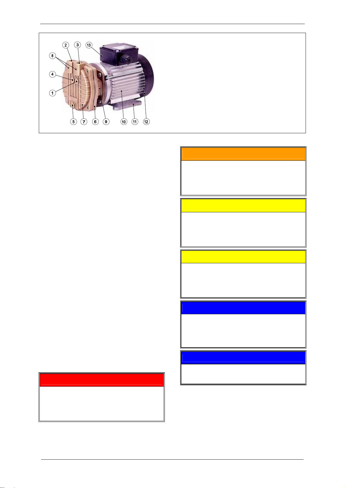
Fig. 1: Design of liquid-ring vacuum
pump/compressor
1 Operating-liquid port
2 Discharge connection
3 Inlet connection
4 Connection for cavitation protection
5 Drain hole
6 Vacuum pump/compressor housing
7 Vacuum pump/compressor cover
8 Flow direction arrows
9 Rotating direction arrow
10 Drive motor
11 Base
12 Fan guard (over external fan)
13 Terminal box
WARNING
1.1 Definitions
To point out dangers and important
information, the following signal words and
symbols are used in these operating
instructions:
1.1.1 Safety alert symbol
The safety alert symbol
is located in the
safety precautions in the highlighted heading
field on the left next to the signal word
(DANGER, WARNING, CAUTION).
Safety precautions with a safety alert symbol
indicate a danger of injuries.
Be sure to follow these safety precautions to
protect against injuries or death!
Safety precautions without a safety alert
symbol indicate a danger of damage.
1.1.2 Signal words
DANGER
WARNING
CAUTION
NOTICE
NOTE
The signal words are located in
the safety precautions in the
highlighted heading field.
They follow a certain hierarchy
and indicate
(in conjunction with the safety
alert symbol, see Chapter 1.1.1)
the seriousness of the danger
and the type of warning.
See the following explanations:
DANGER
Danger of injuries.
Indicates an imminently hazardous situation,
that will result in death or serious injury if the
corresponding measures are not taken.
Danger of injuries.
Indicates a potentially hazardous situation, that
could result in death or serious injury if the
corresponding measures are not taken.
CAUTION
Danger of injuries.
Indicates a potentially hazardous situation, that
may result in minor or moderate injury if the
corresponding measures are not taken.
CAUTION
Danger of damage.
Indicates a potentially hazardous situation that
may result in property damage if the
corresponding measures are not taken.
NOTICE
Indicates a possible disadvantage, i.e.
undesirable conditions or consequences can
occur if the corresponding measures are not
taken.
NOTE
Indicates a possible advantage if the
corresponding measures are taken; tip.
© Gardner Denver Deutschland GmbH 3 / 32 610.444430.40.000
Page 4
Safety
1.2 General safety precautions
WARNING
Improper use of the unit can result in
serious or even fatal injuries!
These operating instructions
must have been read completely and
understood before beginning any work with
or at the pump-motor unit,
must be strictly observed,
must be available at the operating location
of the pump-motor unit.
WARNING
Improper use of the unit can result in
serious or even fatal injuries!
Only operate the pump-motor unit
for the purposes indicated under "Intended
Use"!
with the fluids indicated under 'Intended
Use'!
with the values indicated under 'Technical
Data'!
WARNING
Improper use of the unit can result in
serious or even fatal injuries!
All work on and with the pump-motor unit
(transport, installation, operation, shut-down,
maintenance, disposal) may only be carried
out by trained, reliable expert personnel!
WARNING
When working on the unit, there is a danger
of injury, e.g. in the form of cuts/cutting off,
crushing and burns!
During all work on and with the pump-motor
unit (transport, installation, operation, shut-
down, maintenance, disposal) wear personal
safety equipment (safety helmet, protective
gloves, safety shoes)!
WARNING
Hair and clothing can be pulled into the unit
or caught and wound up moving parts!
Do not wear long, loose hair or wide, loose
clothes! Use a hair net!
DANGER
Electrical danger!
Before beginning work on the unit or system,
the following measures must be carried out:
Deenergize.
Secure against being switched on again.
Determine whether deenergized.
Ground and short-circuit.
Cover or block off adjacent energized parts.
DANGER
Electrical danger!
Work on electrical installations may be carried
out by trained and authorized electricians only!
DANGER
Electrical danger!
Replace loose connections, singed or burned
cables immediately!
DANGER
Electrical danger!
Do not open the motor terminal box unless
absence of electricity has been ensured!
DANGER
Electrical danger!
Depending on the charging state of the
capacitors, a residual voltage may be present
on the terminals in the terminal box.
After opening the terminal box cover, it must
be ensured that the capacitors are completely
deenergized:
Measure the voltage at the corresponding
jumpers (see the circuit diagram in the
terminal box).
Dissipate the residual voltage with suitable
means if necessary.
The capacitors must be completely
deenergized.
WARNING
Danger due to gauge pressure and vacuum!
Danger due to escaping fluid!
Before beginning work on the unit or system:
Interrupt supply of operating liquid.
Bleed lines and vacuum pump/compressor
(depressurize).
610.444430.40.000 4 / 32 © Gardner Denver Deutschland GmbH
Page 5
Safety
WARNING
Danger from rotating external fan of unit!
Only operate the unit with the fan guard
mounted!
It is prohibited to remove the fan guard!
WARNING
Danger from rotating impeller of unit!
Only operate the unit with the vacuum
pump/compressor cover and housing mounted!
It is prohibited to remove the vacuum
pump/compressor cover and the housing!
WARNING
Danger due to gauge pressure and vacuum!
Danger due to escaping fluid!
Danger from rotating impeller of unit!
Only operate the unit with the pipes/hoses
connected to the intake and discharge
connection, as well as to the operating-liquid
port!
WARNING
Danger in the form of cuts or cutting off
extremities on the impeller of the pumpmotor unit!
Do not reach into the unit through open
connections!
Do not insert objects into the unit through the
openings!
WARNING
Danger due to gauge pressure and vacuum!
Check the lines and containers used for
sufficient strength!
WARNING
Danger due to gauge pressure and vacuum!
Danger due to escaping fluid!
Check the connections of the pipe/hose
connections for leaks!
WARNING
Danger of burns and scalding from hot
surfaces of the pump-motor unit and from
hot fluids!
Do not touch during operation!
Allow to cool after shut-down!
CAUTION
Danger of crushing from unit tipping over!
Secure the pump-motor unit on the installation
surface before putting into operation!
1.3 Residual risks
WARNING
Danger zone:
Fan guard
Hazard:
Long, loose hair can be drawn into external fan
through fan guard grate, even with fan guard
mounted!
Protective measures:
Wear hair net!
WARNING
Danger zone:
Hot surface.
Hazard:
Burns/scalding possible.
Protective measures:
Do not touch! Wear protective gloves!
© Gardner Denver Deutschland GmbH 5 / 32 610.444430.40.000
Page 6

Intended Use
2 Intended Use
These operating instructions
applies to liquid-ring vacuum
pumps/compressors of the series L-BV3,
model 2BV3151,
contain instructions bearing on transport
and handling, installation, commissioning,
operation, shut-down, storage, servicing
and disposal of the L-BV3,
must be completely read and understood by
all operating and servicing personnel before
beginning to work with or on the L-BV3,
must be strictly observed,
must be available at the site of operation of
the L-BV3.
About the operating and servicing personnel of
the L-BV3:
These persons must be trained and
authorized for the work to be carried out.
Work on electrical installations may be
carried out by trained and authorized
electricians only.
The L-BV3
are pump-motor units for generating
vacuum or gauge pressure.
are used to extract, transport and compress
the following pumped gases/vapors:
– all dry and humid gases,
which are not explosive, aggressive or
toxic,
– preferably air or air/vapor mixtures.
– The gases/vapors to be fed must be free
of solid material.
However, small quantities of light
suspended materials or liquids can also
be transported.
are designed for operation with the
following operating liquids:
– Water
with a pH of 6.5 to 9.5,
free of solid materials (such as sand).
– If the pH values or operating liquids
differ, it is necessary to contact the
Service Department.
have the rough vacuum range as the
intended operating range.
are intended for industrial applications.
are designed for continuous operation.
When operating the L-BV3, the limits listed in
Chapter 3, "Technical Data", Pg. 7 ff. must
always be complied with.
If the L-BV3 is used to extract hot fluids, the
necessary safety measures must be taken by
the user.
Foreseeable Misuse
It is prohibited
to use the L-BV3 in applications other than
industrial applications
unless the necessary protection is provided
on the system,
e.g. guards suitable for children's fingers,
to use the L-BV3 in rooms in which
explosive gases can occur,
the sucking up, feeding and compression of
explosive, flammable, aggressive or toxic
fluids,
to operate the L-BV3 with values other than
those specified in Chapter 3, "Technical
Data", Pg. 7 ff.
Any unauthorized modifications of the L-BV3
are prohibited for safety reasons.
Maintenance and repair work by the operator
are only permitted in the scope described in
these operating instructions.
Any maintenance and repair work going
beyond this may only be conducted by
companies authorized by the manufacturer
(inquiry with the Service Department
necessary).
610.444430.40.000 6 / 32 © Gardner Denver Deutschland GmbH
Page 7
3 Technical Data
3.1 Mechanical data
Weight
Technical Data
Tightening torques
The values specified here for tightening
torques apply unless other values are
indicated.
Type Weight
approx.
[kg]
2BV3151 9 19.8
approx.
[lbs]
Thread [Nm]
Higher weights are possible with special
models.
Minimum distances for heat dissipation
Type Minimum distance from
fan guard to adjacent surface
[mm] [inches]
2BV3151 20 0.787
G⅛ 4.5 3.32
G⅜ 16 11.8
Thread [Nm]
Noise level
Measuring-surface sound-pressure level
according to EN ISO 3744 measured at a
distance of 1 m [3.28 ft] with moderate
throtteling (8 kPa abs. [1.16 psia]) and lines
connected.
Type 1-m measuring-surface sound
pressure level L [dB (A)
at 50 Hz: at 60 Hz:
2BV3151 70 70
M4 1.0 0.738
M5 2.2 1.62
These values for electrical connections applies
to all terminal board connections with the
exception of modular terminal blocks.)
Thread [Nm]
Operating speed
See rating plate.
NOTICE
Exceeding of the operating speed will
negatively affect the operating behavior of the
pump-motor unit:
higher noise emissions
stronger vibrations
shorter grease consumption time
M3 0.6 0.443
(These values for electrical connections apply
to all modular terminal blocks.)
3.2 Electrical data
See drive motor rating plate.
3.3 Operating conditions
Temperatures
reduced bearing change interval
To prevent damage due to excessively high
speeds, it may be necessary to request the
limit speed (inquire with the Service
Department).
Temperature of pumped gases/vapors:
max. +110 °C max. +230 °F
At higher fluid temperatures, measures must
be taken on the system to prevent burns, e.g.
mount separating safety device (cover).
In addition, we also recommend one of the
following measures at temperatures > 80 °C
[> 176 °F]:
Increasing the operating-liquid flow rate by
up to twice the rated liquid flow rate (cooling
circuit)
Use of a series capacitor
Tightening torques
for screw connections
(pipe-connections)
± 10 %
Tightening torques
for electrical connections
(terminal board-connections)
± 10 %
Tightening torques
for electrical connections
(modular terminal blocks)
± 10 %
[ft lbs]
± 10 %
[ft lbs]
± 10 %
[ft lbs]
± 10 %
© Gardner Denver Deutschland GmbH 7 / 32 610.444430.40.000
Page 8
Technical Data
Operating-liquid temperature:
max. +40 °C max. +104 °F
min. +5 °C min. +41 °F
Nominal value:
+15 °C +59 °F
Ambient temperature:
max. +40 °C +104 °F
min. +5 °C +41 °F
Pressures
Min. inlet pressure p
1 min
:
Depending on the type and temperature of the
operating liquid.
During vacuum operation without cavitation
protection (cavitation protection hole closed):
5 kPa 0.725 psi
It may not be dropped below to prevent
damage due to cavitation!
Damage due to cavitation are purposely
disregarded if the minimum inlet pressure is
3.3 kPa [0.479 psi].
The specified values apply to the following
conditions:
Operating liquid:
Water at +15 °C [+59 °F]
pumped gases/vapors:
dry air at +20 °C [68 °F]
They are higher the higher the temperature
and the higher the vapor pressure of the
operating liquid used.
During vacuum operation with cavitation
protection (cavitation protection hole open):
max. achievable vacuum, i.e. complete
throttling
The following generally applies: The higher the
temperature, the lower the intake capacity, i.e.
the higher the minimum achievable inlet
pressure.
Max. discharge pressure p
2 max
during
vacuum operation:
110 kPa abs. 16.0 psia
This value applies, provided the rated
operating-liquid flow rate is adhered to.
Max. discharge pressure (differential
pressure) p
during compressor
2 max
operation (at inlet pressure p1 = 101.3
bar abs. [14.7 psia]):
60 kPa 8.70 psi
This value applies, provided the rated operatingliquid flow rate is adhered to.
Max. permissible pressure in the pumpmotor unit p
during compressor
int max
operation:
300 kPa abs. 43.5 psia
If higher pressures can occur in the system, then
corresponding protective devices must be provided.
Max. pre-pressure of the operating liquid
300 kPa abs. 43.5 psia
When the permissible operating liquid pressure is
exceeded, too much liquid enters the vacuum
pump/compressor. Damage can occur.
Liquid quantities
Nominal operating-liquid flow rate
(with dry air extraction and with water at 15 °C
[59 °F] as operating liquid)
0.65 l/min 0.172 gal (US)/min 0.143 gal (UK)/min
(0.039 m³/h) (1.38 ft³/h)
Max. filling quantity for operating liquid at a
standstill
0.200 l 0.053 gal (US) 0.044 gal (UK)
Repeated switching on of the pump-motor unit
in the flooded state can result in damage.
Maximum permissible quantity of water
entrained via the inlet connection
3.9 l/min 1.03 gal (US)/min 0.858 gal (UK)/min
If larger quantities can occur, a separator must be
installed upstream on the inlet side.
610.444430.40.000 8 / 32 © Gardner Denver Deutschland GmbH
Page 9

Operating modes
4 Operating modes
The pump-motor unit can function in several
different operating modes.
These differ in how the pump-motor unit is
supplied with operating liquid:
Self-priming operation
Operation with operating-liquid feed:
– Non-automatic operation
– Automatic operation
4.1 Self-priming operation
In this operating mode the pump-motor unit
automatically sucks in the operating liquid.
The operating-liquid flow rate is automatically
adjusted.
See Fig. 4, Pg. 17.
4.2 Operation with operating-liquid feed
In this operating mode the pump-motor unit
DOES NOT automatically suck in the operating
liquid.
A certain volume flow ("nominal operatingliquid flow rate") or pre-pressure must be set
for the operating liquid.
Here the following additional distinctions are
made:
Non-automatic operation
In this case the operating liquid feed is
switched on and off manually with a stop valve.
See Fig. 6, Pg. 19.
Automatic operation
In this case the operating liquid feed is
switched on and off by a solenoid valve. The
solenoid valve is dependent on the motor
operating mode:
Motor/pump-motor unit switched on:
Valve open.
Motor/pump-motor unit switched off:
Valve closed.
See Fig. 7, Pg. 19.
NOTICE
The following is dependent on the operating
mode:
when and how the pump-motor unit must
be filled with operating liquid the first time,
how the pump-motor unit is put into
operation.
The specifications for this are contained in
Chapter 6, "Installation", Pg. 11ff., and
Chapter 7, "Commissioning", Pg. 16ff.
© Gardner Denver Deutschland GmbH 9 / 32 610.444430.40.000
Page 10
Transport and Handling
5 Transport and Handling
WARNING
Improper use of the machine can result in
serious or even fatal injuries!
Have you read the safety precautions in
Chapter 1, "Safety", Pg. 3 f.?
Otherwise you may not carry out any work with
or on the machine!
WARNING
Danger from tipping or falling loads!
Prior to transport and handling make sure that
all components are securely assembled and
secure or remove all components the fasteners
of which have been loosened!
CAUTION
Tipping or falling can lead to crushing,
broken bones etc.!
Sharp edges can cause cuts!
Wear personal safety equipment (protective
helmet, protective gloves, safety shoes) during
transport!
Packing:
In case of a separate delivery, the pump-motor
unit is packed in a carton.
In the case of a group delivery, the pumpmotor units are packed in cardboard boxes or
screen boxes on pallets.
Manual handling:
WARNING
Danger from lifting heavy loads!
Manual handling of the unit is only permitted
within the following limits:
max. 30 kg [max. 66 lbs] for men
max. 10 kg [max. 22 lbs] for women
max. 5 kg [max. 11 lbs] for pregnant women
For the weight of the pump-motor unit, see
Chapter 3.1, "Mechanical data",
Section "Weight", Pg. 7.
For weights above the given values use
suitable lifting appliances and handling
equipment!
WARNING
Danger from tipping or falling loads!
Do not hold the pump-motor unit on the
capacitors or cable glands on the terminal box!
Handling by means of lifting equipment:
WARNING
Danger from tipping or falling loads!
When transporting with lifting equipment,
observe the following basic rules:
The lifting capacity of lifting equipment and
lifting gear must be at least equal to the
unit's weight.
For the weight of the pump-motor unit, see
Chapter 3.1, "Mechanical data",
Section "Weight", Pg. 7.
The pump-motor unit must be secured so
that it cannot tip or fall.
Do not hook the pump-motor unit onto the
capacitors or cable glands on the terminal
box!
Do not stand or walk under suspended
loads!
Use two lifting belts, of which one is routed
under the interface between the motor housing
and the vacuum pumps/compressor housing,
and the other under the interface between the
motor housing and the fan guard.
When transporting the pump-motor unit, make
sure that attached fittings are not damaged.
WARNING
Danger from tipping loads!
Be sure to observe the routing of the strap
belts under the pump-motor unit, even if the
motor is provided with attachment points such
as transport eyes or eye bolts.
These are solely designed for the separate
transport of the motor, however not for the
different weight distribution that results for the
mounted vacuum pump/mounted compressor,
so that the unit could tip!
610.444430.40.000 10 / 32 © Gardner Denver Deutschland GmbH
Page 11

Installation
6 Installation
WARNING
Improper use of the machine can result in
serious or even fatal injuries!
Have you read the safety precautions in
Chapter 1, "Safety", Pg. 3 f.?
Otherwise you may not carry out any work with
or on the machine!
6.1 Installation
CAUTION
Danger of crushing from pump-motor unit
tipping over!
In the unmounted state, the unit can easily tip
due to its weight distribution!
Wear gloves and safety shoes! Handle the unit
with the appropriate care!
CAUTION
Danger of tripping and falling!
Make sure the unit does not present a danger
of tripping!
WARNING
Electrical danger!
The pump-motor unit must be installed so that
the electrical device cannot be damaged by
external influences!
In particular, the feed pipes must be securely
routed, e.g. in cable ducts or in the floor.
CAUTION
Danger of injuries from flying parts!
Select installation so that parts that are thrown
out through the grate if the external fan breaks
cannot hit persons!
CAUTION
Danger of damage to the pump-motor unit
due to overheating!
When installing the unit, make sure that heat
dissipation and cooling are not obstructed. The
minimum distances specified in Chapter 3.1,
"Mechanical data", Section "Minimum
distances for heat dissipation", Pg. 7 must be
complied with.
Discharge air of other units may not be directly
sucked in again!
Minimum distances:
To ensure sufficient cooling of the pump-motor
unit, it is absolutely necessary that the required
minimum distances to the fan guard and to the
face of the vacuum pump/compressor
cover be maintained.
For minimum clearances for heat dissipation
and cooling, see Chapter 3.1, "Mechanical
data", Section "Minimum distances for heat
dissipation", Pg. 7.
Installation conditions:
The pump-motor unit must be installed as
follows:
on flat, level surfaces,
on stationary (fixed) surfaces or structures,
at a maximum height of 1000 m [3280 ft]
above sea level.
For installation under different conditions, the
Service Department must be consulted.
Observe the following when installing the
pump-motor unit:
The load-bearing capacity of the
installation surface must at least be
designed for the weight of the pump-motor
unit.
The vibration behavior at the operating
location must be taken into account.
The total vibrations of the unit are
dependent on the following factors:
– the characteristic vibrations of the unit,
– the alignment and installation,
– the condition (vibration behavior) of the
load-bearing surface,
– the influences by vibrations of other
parts and system components (external
vibrations).
The maximum permissible value for
vibrations is v
= 4.5 mm/s [0.177"/s].
eff
To ensure proper operation and a long
© Gardner Denver Deutschland GmbH 11 / 32 610.444430.40.000
Page 12

Installation
service life of the pump-motor unit, this
value may not be exceeded.
Generally, this value can be adhered to
without a special foundation or a special
base plate.
The points on the unit for measuring the
vibration speed are shown in Fig. 2, Pg. 12.
DANGER
Electrical danger!
Before beginning work on the unit or system,
the following measures must be carried out:
Deenergize.
Secure against being switched on again.
Determine whether deenergized.
Ground and short-circuit.
Cover or block off adjacent energized parts.
DANGER
Electrical danger!
Replace loose connections, singed or burned
cables immediately!
DANGER
Fig. 2: Points for measuring the vibration speed
Securing:
Screw the feet of the pump-motor unit to the
surface with suitable mounting elements.
Proceed as follows:
The feet of the pump-motor unit are
provided with mounting holes.
Select the suitable screw type.
Screw the feet of the pump-motor unit to
the surface with the screws.
When doing so, be sure to provide all
mounting holes with screws!
6.2 Electrical connection (motor)
DANGER
Electrical danger!
Malpractice can result in severe injuries and
material damage!
DANGER
Electrical danger!
Depending on the charging state of the
capacitors, a residual voltage may be present
on the terminals in the terminal box.
After opening the terminal box cover, it must
be ensured that the capacitors are completely
deenergized:
Measure the voltage at the corresponding
jumpers (see the circuit diagram in the
terminal box).
Dissipate the residual voltage with suitable
means if necessary.
The capacitors must be completely
deenergized.
WARNING
Danger due to gauge pressure and vacuum!
Danger due to escaping fluid!
Before beginning work on the unit or system:
Interrupt supply of operating liquid.
Bleed lines and vacuum pump/compressor
(depressurize).
CAUTION
Incorrect connection of the motor can lead to
serious damage to the unit!
Electrical danger!
The electrical connection may be carried out
by trained and authorized electricians only!
610.444430.40.000 12 / 32 © Gardner Denver Deutschland GmbH
Page 13

Regulations:
The electrical connection must be carried out
as follows:
according to the applicable national and
local laws and regulations,
according to the applicable system-
dependent prescriptions and requirements,
Installation
All conductors under outer angled
grounding brackets must be bent into a "U"
shape.
This also applies to:
the protective conductor,
the outer ground conductor.
according to the applicable regulations of
the utility company.
Electrical power supply:
Observe the rating plate.
It is imperative that the operating conditions
correspond to the data given on the rating
plate!
Deviations permissible without reduction in
performance:
±5 % voltage deviation
±2 % frequency deviation
Connection to drive-motor terminal box:
Carry out the connection and the arrangement
of the jumpers in accordance with the circuit
diagram in the terminal box.
Connect the protective conductor to the
terminal with the following symbol:
The electrical connection must be carried out
as follows:
The electrical connection must be
permanently safe.
There may be no protruding wire ends.
Clearance between bare live parts and
between bare live parts and ground: ≥ 5.5
mm [0.217"] (at a nominal voltage of
UN ≤ 690 V).
Tightening torques for terminal plate
connections:
see Chapter 3.1, "Mechanical data",
Section "Tightening torques", Pg. 7.
Use suitable cable lugs.
For terminals with clamping straps, the
conductors must be inserted so that
approximately the same clamping height
results on both sides of the bar.
Individual conductors must therefore be
bent into a U-shape or connected with a
cable lug.
Both conductors can be recognized from their
color (green/yellow).
WARNING
Electrical danger!
Clearance between bare live parts and
between bare live parts and ground:
at least 5.5 mm [0.217"] (at a nominal voltage
of V
≤ 690V)
n
Make sure there are no
protruding pieces of wire!
WARNING
Electrical danger!
The terminal box must be free from
foreign bodies,
dirt,
humidity.
Terminal box cover and cable entries must be
tightly closed so as to make them dustproof
and waterproof.
Check for tightness at regular intervals.
For motor overload protection:
Use motor circuit breakers.
Set the motor circuit breakers to the
nominal current specified on the rating
plate.
© Gardner Denver Deutschland GmbH 13 / 32 610.444430.40.000
Page 14

Installation
6.3 Connecting pipes/hoses (vacuum
pump/compressor)
CAUTION
To prevent foreign bodies from entering the
unit, all connections are sealed off when
delivered.
Do not remove the sealing plugs until
immediately before connecting the
pipes/hoses.
For the arrangement of the pipe/hose
connections, see Fig. 3, Pg. 14.
The pumped gases/vapors are sucked in via
the inlet connection
and discharged via the
discharge connection (see Chapter 6.3.1,
Pg. 15).
For operation the unit must be continuously
supplied with operating liquid.
This is fed in via the operating-liquid port
(see
Chapter 6.3.2, Pg. 15) and discharged
together with the pumped gases/vapors
through the discharge connection
.
If the unit is run dry, the mechanical seal will
be destroyed in a matter of seconds!
DO NOT switch on as long as the unit is not
filled with operating liquid!
Fill with operating liquid:
When and how the pump-motor unit must be
filled with operating liquid the first time is
dependent on the operating mode:
For self-priming operation:
During installation.
For operation with operating-liquid feed:
After completing installation.
For self-priming operation you now pour
operating liquid into the working space of the
pump-motor unit before you connect the
pipes/hoses to the unit.
Proceed as follows:
Pour operating liquid into the open inlet
connection or discharge connection. For
proper filling quantities, see Chapter 3.3,
"Operating conditions", Section "Max. filling
quantity for operating liquid at a standstill",
Pg. 8.
Fig. 3: Pipe/hose connection of vacuum
pump/compressor
1 Operating liquid connection
G⅛", 10 mm [0.394"] deep
2 Discharge connection
G⅜", 12 mm [0.472"] deep
3 Inlet connection
G⅜", 12 mm [0.472"] deep
4 Connection for cavitation protection
G⅛", 10 mm [0.394"] deep
5 Drain hole
G⅛", 10 mm [0.394"] deep
OR
Remove the sealing plug with the seal from
the cavitation protection hole.
Pour operating liquid into the open inlet
connection or discharge connection until
the operating liquid exits from the cavitation
protection hole.
Close the cavitation protection hole with the
sealing plug and seal.
Then attach the pipes/hoses to the unit as
described in the following.
WARNING
Danger due to gauge pressure and vacuum!
Danger due to escaping fluid!
During operation, connected pipes and vessels
are pressurized or vacuumized!
Make sure that all connections are sufficiently
tight! Use only pipes and vessels of sufficient
strength!
610.444430.40.000 14 / 32 © Gardner Denver Deutschland GmbH
Page 15

NOTICE
Installation
6.3.3 Notes
Attach pipes/hoses free of mechanical
tensions.
Support the weight of the pipes/hoses.
6.3.1 Inlet connection and discharge
connection
The inlet connection (Fig. 3, Item 3) is
marked with an arrow pointing downward (↓).
Connect the inlet pipe here. The pumped
gases/vapors are sucked in via this.
The discharge connection (Fig. 3, Item 2) is
marked with an arrow pointing upward (↑).
Connect the discharge pipe here. Both the
pumped gases/vapors and the operating liquid
are discharged via this pipe.
CAUTION
When connecting the pump-motor unit to a
vacuum accumulator:
In this case, a check valve must be installed.
Without a check valve, operating liquid can be
sucked into the system from the pump-motor
unit. Damage to the system can occur!
CAUTION
The tightening torque for pipe connections on
intake and discharge connections (G⅜") may
not exceed 16 Nm ± 10 % [11.8 ft lbs ± 10 %]!
6.3.2 Operating-liquid port
NOTICE
For operating liquid with impurities:
Install a filter, screen or separator in the
supply line if necessary.
NOTICE
In case of operating liquid with a high lime
content:
Soften operating liquid
OR
Decalcify pump-motor unit regularly (see
Chapter 10.1, "Maintenance", Pg. 24).
NOTICE
To prevent installation residues (e.g. welding
spatter) from entering the unit,
a start-up screen should be installed in the inlet
pipe for the first 100 operating hours.
The operating liquid connection (Fig. 3, Item 1)
is located on the face of the vacuum
pump/compressor housing below the inlet
connection.
Connect the feed pipe for the operating liquid
here.
© Gardner Denver Deutschland GmbH 15 / 32 610.444430.40.000
Page 16

Commissioning
7 Commissioning
WARNING
Improper use of the machine can result in
serious or even fatal injuries!
Have you read the safety precautions in
Chapter 1, "Safety", Pg. 3 f.?
Otherwise you may not carry out any work with
or on the machine!
WARNING
Danger due to gauge pressure and vacuum!
Danger due to escaping fluid!
Danger due to rotating parts!
The pump-motor unit may only be put into
operation when the following conditions are
met:
Fan guard and vacuum pump/compressor
cover and housing are mounted.
The lines to the discharge connection, inlet
connection and operating-liquid port are
attached.
The lines and connections have been
tested for strength and leaks.
CAUTION
If the unit is run dry, the mechanical seal will
be destroyed in a matter of seconds!
DO NOT switch on as long as the unit is not
filled with operating liquid!
7.1 Preparation and start-up
CAUTION
If the pumped gases/vapors discharged on the
pressure side are passed on,
then it must be ensured that the maximum
discharge pressure of 110 kPa abs. [16.0 psia]
is not exceeded!
NOTICE
Fill with operating liquid:
For operation with self-priming of the
operating liquid during installation (see
Chapter 6.3, "Connecting pipes/hoses
(vacuum pump/compressor)", Pg. 14).
For operation with operating-liquid feed,
you now fill the working area of the unit with
operating liquid.
Proceed as follows:
Remove the sealing plug with the seal from
the cavitation protection hole.
Open the respective shut-off valve until the
operating liquid exits from the cavitation
protection hole:
– For non-automatic operation:
Stop valve (Fig. 6, Pg. 19, Item 4).
– For automatic operation:
Stop valve in the bypass pipe (Fig. 7,
Pg. 19, Item 4a).
Close the shut-off valve again.
Close the cavitation protection hole with the
sealing plug and seal.
Then proceed with commissioning as
described in the following.
Check connections of the pipes/hoses for
leaks.
Check direction of rotation:
The direction of flow of the pumped
gases/vapors is marked with arrows on the
intake and discharge connection.
The intended shaft rotating direction is
marked with an arrow on the vacuum
pump/compressor housing.
The pump-motor unit may not be allowed to
run dry!
Have you filled it with operating liquid
beforehand (during or after installation)?
See sections "Fill with operating liquid",
Pg. 14 and Pg. 16.
Briefly switch on pump-motor unit.
Maximum permissible quantity of water
entrained via the inlet connection:
See Fig. 9, Pg. 19.
Compare the actual rotating direction of the
external fan with the intended shaft rotating
direction as it is indicated with the arrow on
the vacuum pump/compressor housing of
the pump-motor unit (Fig. 1, Pg. 3, Item 9).
If a shut-off device is installed in the discharge
pipe:
Make sure that the unit CANNOT be operated
with the shut-off device closed.
610.444430.40.000 16 / 32 © Gardner Denver Deutschland GmbH
Switch off pump-motor unit again.
If necessary, reverse the direction of
rotation of the motor.
Page 17

DANGER
Electrical danger!
The electrical connection may be carried out
by trained and authorized electricians only!
DANGER
Electrical danger!
Before beginning work on the unit or system,
the following measures must be carried out:
Deenergize.
Secure against being switched on again.
Determine whether deenergized.
Ground and short-circuit.
Cover or block off adjacent energized parts.
DANGER
Electrical danger!
Depending on the charging state of the
capacitors, a residual voltage may be present
on the terminals in the terminal box.
After opening the terminal box cover, it must
be ensured that the capacitors are completely
deenergized:
Measure the voltage at the corresponding
jumpers (see the circuit diagram in the
terminal box).
Dissipate the residual voltage with suitable
means if necessary.
The capacitors must be completely
deenergized.
WARNING
Danger due to gauge pressure and vacuum!
Danger due to escaping fluid!
Before beginning work on the unit or system:
Interrupt supply of operating liquid.
Bleed lines and vacuum pump/compressor
(depressurize).
The further procedure is again dependent
on the unit operating mode:
Commissioning
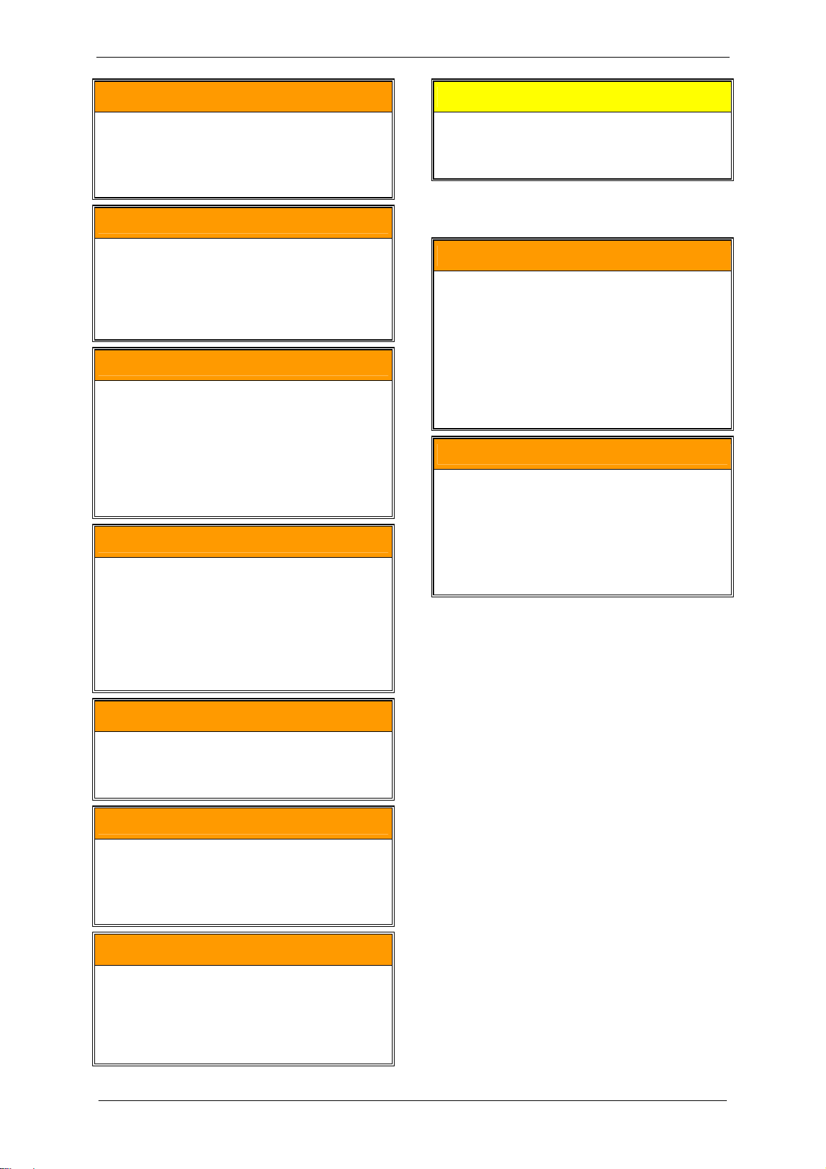
7.2 Self-priming operation
CAUTION
The liquid level in the feed pipe or in the
reservoir may not exceed the height of the
shaft center of the pump-motor unit!
If this height is exceeded, too much liquid gets
into the pump-motor unit. Damage can occur!
See Fig. 4, Pg. 17.
Here the following must be watched:
The pump-motor unit must be pre-throttled
on the inlet side. This means a vacuum of
at least 80 kPa abs. [11.6 psia] must be
present in the inlet pipe (Item B) at switchon.
During switch-on, the liquid level in the feed
pipe (Item A) and in the reservoir (Item C)
respectively must be at the same level as
the center of the unit shaft (Item 1).
During operation the liquid level in the
reservoir (Item C) may not drop below
approx. 1 m [3.28 ft] below the center of
the unit shaft (Item 1).
80 kPa abs
11,6 psia
6104443001005
Fig. 4: Self-priming operation
A Feed pipe for operating liquid
B Inlet pipe
C Reservoir for operating liquid
1 Required liquid level when switching on
2 Min. liquid level during operation
Starting the pump-motor unit:
B
A
1
1 m
2
3,28 ft
C
Switch on the unit.
The operating liquid is sucked in.
© Gardner Denver Deutschland GmbH 17 / 32 610.444430.40.000
Page 18

Commissioning
7.3 Operation with operating-liquid feed
For automatic operation (Fig. 7, Pg. 19):
See Fig. 5, Pg. 18, and Fig. 8, Pg. 19, as well
as Fig. 6, Pg. 19, and Fig. 7, Pg. 19.
Proceed as follows here:
Method A:
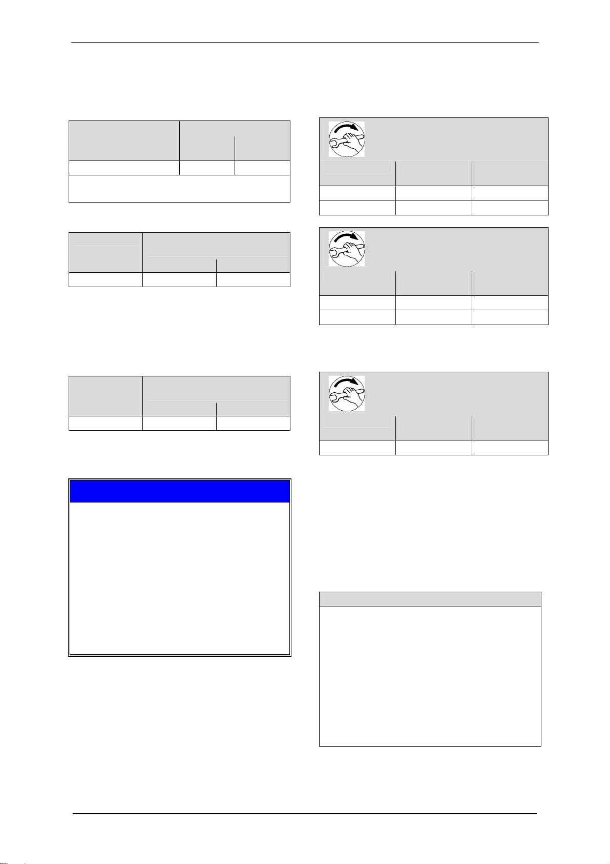
1) Set pre-pressure of operating liquid (Fig. 5,
Pg. 18):
Set a pre-pressure p
in the feed pipe for
A
the operating liquid (Item A) around
approx. 100 kPa [14.5 psi] above the inlet
pressure p
in the inlet pipe (Item B).
B
B
PA=PB+100 kPa
P
A=PB
6104443001006
A
+14,5 psi
Fig. 5: Setting the operating-liquid flow rate:
Setting pre-pressure
A Feed pipe for operating liquid
B Inlet pipe
2) Start up the unit:
For non-automatic operation (Fig. 6, Pg. 19):
Open the stop valve (Item 4) manually.
The operating liquid is fed in.
Switch on the unit.
Switch on the unit.
The solenoid valve (Item 4) opens
and the operating liquid is fed in.
Method B:
1) Start up the unit:
For non-automatic operation (Fig. 6, Pg. 19):
Open the stop valve (Item 4) manually.
The operating liquid is fed in.
Switch on the unit.
For automatic operation (Fig. 7, Pg. 19):
Switch on the unit.
The solenoid valve (Item 4) opens
and the operating liquid is fed in.
2) Check the operating-liquid flow rate:
with the flow meter (Fig. 6, Pg. 19, and
Fig. 7, Pg. 19, Item 2)
OR
by measuring the volume of operating liquid
per unit of time that exits at the discharge
connection with a graduated vessel (Fig. 8,
Pg. 19)
3) Set/correct the operating-liquid flow rate:
via the control valve (Fig. 6, Pg. 19, and
Fig. 7, Pg. 19, Item 3)
Nominal operating-liquid flow rate:
For nominal values, see Chapter 3.3,
"Operating conditions", Section "Nominal
operating-liquid flow rate", Pg. 8.
610.444430.40.000 18 / 32 © Gardner Denver Deutschland GmbH
Page 19

Commissioning
23
1
6104443001008
45
6
23
1
6104443001009
45
4a
6
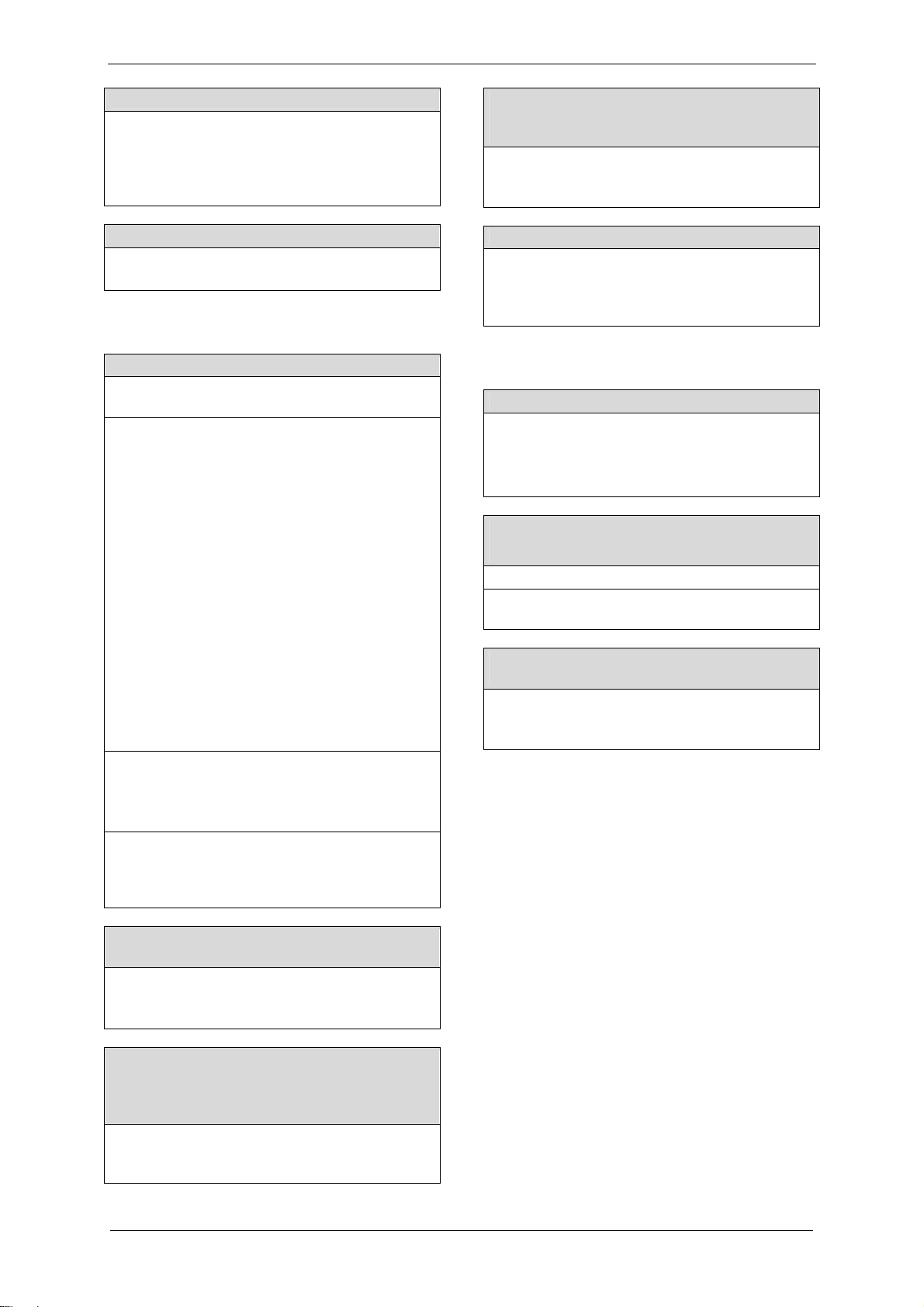
Fig. 6: Operation with operating-liquid feed:
Non-automatic operation
Fig. 7: Operation with operating-liquid feed:
Automatic operation
1 Pump-motor unit
2 Flow meter
3 Control valve
4 Stop valve
5 Dirt trap
6 Feed pipe for operating liquid
1 Pump-motor unit
2 Flow meter
3 Control valve
4 Solenoid valve, connected to motor
4a Bypass with stop valve (for priming)
5 Dirt trap
6 Feed pipe for operating liquid
B
A
3x4x
1x
6104443001007
6104443001010
Fig. 8: Setting the operating-liquid flow rate:
Measuring the volume with a graduated vessel
A Feed pipe for operating liquid
B Drain pipe for operating liquid
Fig. 9: Maximum permissible quantity of water
entrained via the inlet connection
3x quantity of operating-liquid flow rate
© Gardner Denver Deutschland GmbH 19 / 32 610.444430.40.000
Page 20

Operation
8 Operation
WARNING
Improper use of the machine can result in
serious or even fatal injuries!
Have you read the safety precautions in
Chapter 1, "Safety", Pg. 3 f.?
Otherwise you may not carry out any work with
or on the machine!
WARNING
Danger due to gauge pressure and vacuum!
Danger due to escaping fluid!
Danger due to rotating parts!
The pump-motor unit may only be put into
operation when the following conditions are
met:
Fan guard and vacuum pump/compressor
cover and housing are mounted.
The lines to the discharge connection, inlet
connection and operating-liquid port are
attached.
The lines and connections have been
tested for strength and leaks.
CAUTION
If the unit is run dry, the mechanical seal will
be destroyed in a matter of seconds!
DO NOT switch on as long as the unit is not
filled with operating liquid!
WARNING
Danger of burns and scalding from hot
surfaces of the pump-motor unit and from
hot fluids!
Do not touch during operation!
Allow to cool after shut-down!
NOTICE
Maximum permissible quantity of water
entrained via the inlet connection:
See Fig. 9, Pg. 19.
CAUTION
The feeding in of overheated steam at the inlet
connection of the pump-motor unit while it is
not rotating has the following effect:
Operating liquid is pressed out of the pump-
motor unit.
Considerable thermal loading of the pump-
motor unit.
The pump-motor unit may be damaged!
Before feeding in overheated steam at the inlet
connection, switch on the pump-motor unit for
approx. 10 s to ensure sufficient supply with
operating liquid. The operating liquid cools the
pump-motor unit.
8.1 Self-priming operation
Follow the instructions contained in
Chapter 7.2, "Self-priming operation", Pg. 17
for this operating mode.
8.2 Operation with operating-liquid feed
Start-up
For non-automatic operation (Fig. 6, Pg. 19):
Open the stop valve (Item 4) manually.
The operating liquid is fed in.
Switch on the unit.
For automatic operation (Fig. 7, Pg. 19):
Switch on the unit.
The solenoid valve (Item 4) opens
and the operating liquid is fed in.
Shut down:
For non-automatic operation (Fig. 6, Pg. 19):
Switch off the pump-motor unit.
Close the stop valve (Item 4) manually.
Feeding of the operating liquid is cut off.
The following applies for the control valve
(Item 3) for setting the operating-liquid flow
rate:
In case of an interruption in operation, the
valve setting (i.e. the valve position or the
open valve cross-section) is not changed.
© Gardner Denver Deutschland GmbH 20 / 32 610.444430.40.000
Page 21

For automatic operation (Fig. 7, Pg. 19):
Switch off the pump-motor unit.
The solenoid valve (Item 4) closes,
and feeding of the operating liquid is cut off.
The following applies for the control valve
(Item 3) for setting the operating-liquid flow
rate:
In case of an interruption in operation, the
valve setting (i.e. the valve position or the
open valve cross-section) is not changed.
Operation
© Gardner Denver Deutschland GmbH 21 / 32 610.444430.40.000
Page 22

Shut-Down and Longer Standstills
9 Shut-Down and Longer
Standstills
Disconnect the hose connections on the
inlet connection, discharge connection and
operating liquid opening.
WARNING
Improper use of the machine can result in
serious or even fatal injuries!
Have you read the safety precautions in
Chapter 1, "Safety", Pg. 3 f.?
Otherwise you may not carry out any work with
or on the machine!
9.1 Draining
DANGER
Electrical danger!
Before beginning work on the unit or system,
the following measures must be carried out:
Deenergize.
Secure against being switched on again.
Determine whether deenergized.
Ground and short-circuit.
Cover or block off adjacent energized parts.
WARNING
Danger due to gauge pressure and vacuum!
Danger due to escaping fluid!
Before beginning work on the unit or system:
Interrupt supply of operating liquid.
Bleed lines and vacuum pump/compressor
(depressurize).
Switch off the pump-motor unit.
Remov ethe mounting screws on the feet of
the pump-motor unit.
Place the pump-motor unit on the vacuum
pump/compressor cover and tilt it several
times over the connection.
Remount the mounting screws on the feet.
Reattach the hoses.
9.2 Preparing for longer standstill
Before a longer standstill (from approx.
4 weeks) or when there is danger of frost,
proceed as follows:
Drain pump-motor unit as described in
Chapter 9.1, "Draining", Pg. 22.
Remove the pipe/hose from the intake or
discharge connection.
Pour ¼ l [0.066 gal (US); 0.055 gal (UK)] of
preservative (rust protection oil, e.g.
Mobilarma 247 form Mobil Oil)
into the open intake or discharge
connection.
Close the intake and discharge connection,
as well as the operating-liquid port and
remount the disconnected pipes/hoses.
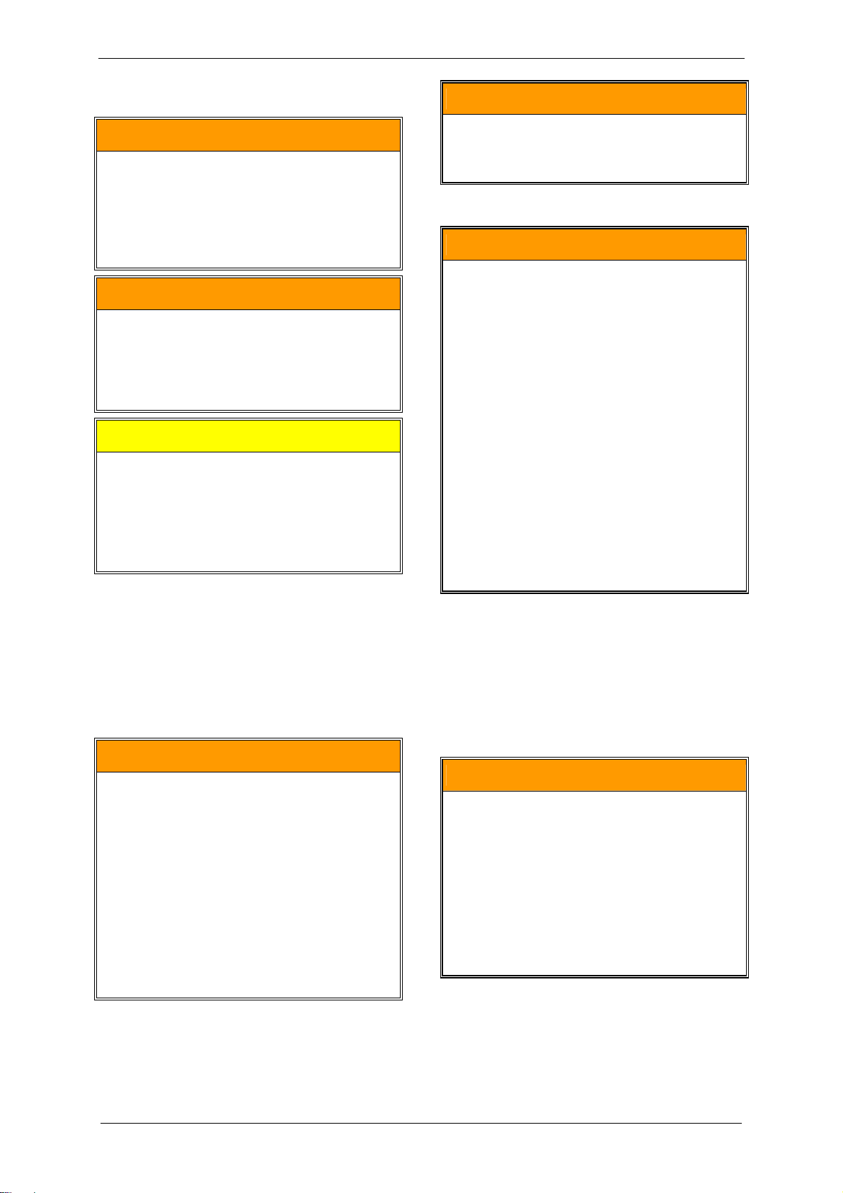
Guide a screwdriver through the central
opening in the fan guard up to the shaft end
on the external fan side (see Fig. 10,
Pg. 23).
Turn the shaft by hand using the
screwdriver.
The above safety precautions apply when
working on the unit or system.
Provide suitable catch containers below the
vacuum pump/compressor cover.
Open the sealing plug of the drain hole
(Fig. 3, Pg. 14, Item 5).
Remove the screwdriver again.
You have two options for the standstill:
Either the pump-motor unit remains
connected in the system,
or the unit is removed for storage.
Allow the liquid to drain out.
Colse the sealing plug again,
tightening torque for G⅛" = 4.5 Nm ± 10 %
[3.32 ft lbs ± 10 %].
OR
Switch off the pump-motor unit.
The above safety precautions apply when
working on the unit or system.
Have a suitable catch container ready.
610.444430.40.000 22 / 32 © Gardner Denver Deutschland GmbH
Page 23

Shut-Down and Longer Standstills
described in Chapter 7, "Commissioning",
Pg. 16.
For pump-motor unit that are already
installed in a system:
Commission the pump-motor unit as
described in Chapter 7, "Commissioning",
Pg. 16.
DANGER
Electrical danger!
Work on electrical installations may be carried
out by trained and authorized electricians only!
6104443001004
Fig. 10: Pour in preservative and turn shaft
9.3 Storage conditions
This chapter applies in the following cases:
new pump-motor units,
pump-motor unit that are already installed
in a system and were prepared for a longer
standstill, as described in Chapter 9.2,
"Preparing for longer standstill", Pg. 22.
To prevent standstill damage during storage,
the environment must provide the following
conditions:
dry,
dust-free,
low-vibration (effective value of vibration
speed v
≤ 0.2 mm/s [0.008"/sec]).
eff
Take the following measures for
commissioning following a longer
standstill:
Measure the insulation resistance of the
motor.
In case of values ≤ 1kΩ per volt of nominal
voltage, dry winding.
Drain off preservative, as described in
Chapter 9.1, "Draining", Pg. 22.
Subsequent cleaning of the pump-motor
unit is not required.
Dispose of preservative in accordance with
the manufacturer's specifications.
For new pump-motor units:
Install pump-motor unit as described in
Chapter 6, "Installation", Pg. 11.
Commission the pump-motor unit as
© Gardner Denver Deutschland GmbH 23 / 32 610.444430.40.000
Page 24

Servicing
10 Servicing
WARNING
Improper use of the machine can result in
serious or even fatal injuries!
Have you read the safety precautions in
Chapter 1, "Safety", Pg. 3 f.?
Otherwise you may not carry out any work with
or on the machine!
WARNING
Improper use of the unit can result in
serious or even fatal injuries!
All maintenance work on the pump-motor unit
must always be performed by the Service
Department!
Inquire with the Service Department!
DANGER
Electrical danger!
Before beginning work on the unit or system,
the following measures must be carried out:
Deenergize.
Secure against being switched on again.
Determine whether deenergized.
Ground and short-circuit.
Cover or block off adjacent energized parts.
DANGER
Electrical danger!
Replace loose connections, singed or burned
cables immediately!
DANGER
WARNING
Danger due to gauge pressure and vacuum!
Danger due to escaping fluid!
Before beginning work on the unit or system:
Interrupt supply of operating liquid.
Bleed lines and vacuum pump/compressor
(depressurize).
WARNING
Danger from rotating external fan of unit!
It is prohibited to remove the fan guard!
WARNING
Danger from rotating impeller of unit!
It is prohibited to remove the vacuum
pump/compressor cover and the housing!
WARNING
Danger of burns and scalding from hot
surfaces of the pump-motor unit and from
hot fluids!
Do not touch during operation!
Allow to cool after shut-down!
10.1 Maintenance
The pump-motor unit is largely maintenancefree.
If water containing lime is used as the
operating liquid, the operating liquid must be
softened or the pump-motor unit must be
decalcified at regular intervals.
Refer to the following table:
Electrical danger!
Depending on the charging state of the
capacitors, a residual voltage may be present
on the terminals in the terminal box.
After opening the terminal box cover, it must
be ensured that the capacitors are completely
deenergized:
Measure the voltage at the corresponding
jumpers (see the circuit diagram in the
terminal box).
Dissipate the residual voltage with suitable
means if necessary.
The capacitors must be completely
deenergized.
610.444430.40.000 24 / 32 © Gardner Denver Deutschland GmbH
Page 25

Contamination/Problem Remedy
Servicing
Dirt collects in the motor
cooling fins.
Fine-grain dirt (e.g. sand) get
into the vacuum
pump/compressor with the
Clean the motor cooling fins at regular intervals.
Install a liquid separator, filter or screen in the feed pipe.
It is prohibited to remov ethe vacuum pump/compressor housing!
operating liquid or pumped
gases/vapors.
Impeller is jammed. Free shaft by turning.
To do so, proceed as follows:
Shut unit down.
Guide a screwdriver through the central opening in the fan guard up to the
shaft end on the external fan side (see Fig. 10, Pg. 23).
Turn the shaft by hand using the screwdriver.
Remove the screwdriver again.
Extremely hard water used
as operating liquid
Lime content > 15°dH).
Soften operating liquid.
OR
Decalcify the pump-motor unit at intervals of 3 months.
To do this, proceed as follows (also see Fig. 11, Pg. 26):
Wear personal protective equipment (protective gloves and safety
goggles),
Shut unit down.
Drain pump-motor unit as described in Chapter 9.1, "Draining", Pg. 22.
Remove pipes/hoses.
Fill the unit with decalcifying liquid through one of the connection
openings. Use 10% solution of acetic acid or another commercially
available decalcifying agent.
Allow the decalcifying liquid to soak for at least 30 minutes.
Turn the shaft occasionally during this time. To do this, guide a
screwdriver through the central opening in the fan guard up to the shaft
end on the external fan side (see Fig. 11, Pg. 26).
Turn the shaft using the screwdriver.
Remove the screwdriver again.
Drain the decalcifying liquid out of the unit. To do this, proceed as
described in Chapter 9.1, "Draining", Pg. 22.
Mount pipes/hoses.
When commissioning the pump-motor unit, proceed as described in
Chapter 7, "Commissioning", Pg. 16.
The decalcifier can be disposed of in the sewer system.
Dirt gets into the air
passages (fan guard,
external fan, cooling fins) of
the motor.
Clean the motor air passages regularly.
To do so, proceed as follows:
Carry out protective measures for the use of compressed air:
Wear personal protective equipment (protective gloves and safety
goggles),
secure surroundings. Remove objects lying around.
Blow in compressed air through the fan guard grate.
It is prohibited to remove the fan guard!
© Gardner Denver Deutschland GmbH 25 / 32 610.444430.40.000
Page 26

Servicing
6104443001004
Fig. 11: Pouring in decalcifying agent and freeing shaft by turning
10.2 Repairs/troubleshooting
Fault Cause Remedy Carried out by
Motor does
not start, no
running
noise.
Interruption of the
power supply,
with single-phase
model in one
Check fuses, terminals and cables for open
circuit. Eliminate open circuit.
Electrician
cable, with twophase model in at
least two cables.
Motor does
not start,
humming
One power
supply lead
interrupted.
Check fuses, terminals and cables for open
circuit. Eliminate open circuit.
Electrician
noises.
Impeller is
jammed.
Free shaft by turning.
See Chapter 10.1, "Maintenance", Pg. 24.
Operator
Decalcify vacuum pump/compressor.
Operator
See Chapter 10.1, "Maintenance", Pg. 24.
Drain and clean vacuum pump/compressor if
Operator
necessary.
See Chapter 10.1, "Maintenance", Pg. 24.
Check and correct impeller gap setting if
Service
necessary.
Impeller
Replace impeller. Service
defective.
Motor bearings
Replace motor bearings. Service
defective.
610.444430.40.000 26 / 32 © Gardner Denver Deutschland GmbH
Page 27

Servicing
Fault Cause Remedy Carried out by
Protective
motor switch
trips when
motor is
switched on.
consumption
too high.
Unit does not
generate
vacuum.
Winding shortcircuit.
Motor
overloaded.
Counter-pressure
at discharge
connection too
high.
Share of liquid
also fed too high.
Impeller is
jammed.
Lime or other
deposits.
No operating
liquid present.
Have winding checked. Electrician
Check operating-liquid flow rate and reduce if
Operator
necessary.
See Chapter 7.2, "Self-priming operation", Pg. 17
or 7.3, "Operation with operating-liquid feed",
Pg. 18.
Reduce counter-pressure. Operator
Reduce share of liquid also fed. Operator
See "Motor does not start, humming noises." Operator/Service
Decalcify vacuum pump/compressor.
Operator Power
See Chapter 10.1, "Maintenance", Pg. 24.
Clean vacuum pump/compressor.
Operator
See Chapter 10.1, "Maintenance", Pg. 24.
Ensure proper operating-liquid flow rate.
Operator
See Chapter 7.2, "Self-priming operation", Pg. 17
or Chapter 7.3, "Operation with operating-liquid
feed", Pg. 18.
Unit
generates
insufficient
vacuum.
Severe leak in the
Seal leak in the system. Operator
system.
Wrong direction
of rotation.
Reverse direction of rotation by interchanging two
connecting leads.
Electrician
Unit too small. Use larger unit. Operator
Operating-liquid
flow too low.
Increase operating-liquid flow rate to up to 2x the
nominal flow rate.
Operator
See Chapter 7.2, "Self-priming operation", Pg. 17
or Chapter 7.3, "Operation with operating-liquid
feed", Pg. 18.
Operating liquid
too warm
(nominal
temperature:
Cool or increase operating-liquid flow,
See Chapter 7.2, "Self-priming operation", Pg. 17
or 7.3, "Operation with operating-liquid feed",
Pg. 18.
Operator
15°C [59 °F]).
Inspect impeller. Replace impeller if necessary. Service Erosion.
Replace affected components. Service
Leak in system. Seal leak in the system. Operator
Mechanical seal
Replace mechanical seal. Service
leaky.
Screeching
noises.
Cavitation of
vacuum
pump/compressor
Connect cavitation-protection hose of liquid
separator or clean cavitation-protection
equipment.
Operator
.
© Gardner Denver Deutschland GmbH 27 / 32 610.444430.40.000
Page 28

Servicing
Fault Cause Remedy Carried out by
Operating-liquid
flow rate too high.
Check operating-liquid flow rate and reduce if
necessary.
Operator
See Chapter 7.3, "Operation with operating-liquid
feed", Pg. 18.
Pump-motor unit
is started while
flooded.
Check operating-liquid flow rate and reduce if
necessary. After switching off pump-motor unit,
no operating liquid may be fed in.
Operator
See Chapter 7.3,“Operation with operating-liquid
feed“, Pg. 18.
Unit leaky. Seals defective. Check seals. Service
610.444430.40.000 28 / 32 © Gardner Denver Deutschland GmbH
Page 29

10.3 Service/After-sales service
Our Service is available for work (in particular
the installation of spare parts, as well as
maintenance and repair work), not described in
these operating instructions (see front page of
these operating instructions).
Observe the following when returning pump-
motor unit:
Before shipping:
– Drain the pump-motor unit so that it is
residue-free,
as described in Chapter 9.1, "Draining",
Pg. 22.
– Clean the unit on the outside,
as described in Chapter 10.1,
"Maintenance", Pg. 24.
The pump-motor unit must be delivered
complete, i.e. not dismantled.
Only the original packing should be used for
shipment.
A declaration of clearance must be included
with the shipment,
as described in Chapter 10.4,
"Decontamination and Declaration of
Clearance", Pg. 29.
The original rating plate of the pump-motor
unit must be properly mounted, intact and
legible.
All warranty claims are voided for pumpmotor units delivered for a damage
expertise without the original rating plate or
with a destroyed original rating plate.
In case of warranty claims, the
manufacturer must be informed of the
operating conditions, operating duration etc.
and additional detailed information provided
on request if necessary.
10.4 Decontamination and Declaration of
Clearance
WARNING
Danger from flammable, caustic or toxic
substances!
To protect the environment and persons, the
following applies:
Pump-motor unit which have come into contact
with dangerous substances must always be
decontaminated before being passed on to a
workshop!
Disposal
A so-called Declaration of Clearance must be
included with each pump-motor unit that is
given to a workshop for inspection,
maintenance or repair.
The declaration of clearance
is provided as a pre-printed form for
photocopying on page 31,
is legally binding,
must be filled out and signed by authorized,
qualified personnel,
must be issued for each unit sent in (i.e. a
separate declaration for each unit),
must be attached outside on the packing of
the unit,
should be sent to as a copy by fax the
workshop conducting the work prior to
shipment.
This ensures
that the unit has not come into contact with
dangerous substances,
that a unit that has come into contact with
dangerous substances has been sufficiently
decontaminated,
that the inspection, maintenance or repair
personnel can take the required protective
measures if necessary.
NOTICE
The inspection/maintenance/ repair of the unit
at the workshop will not be begun
until the declaration of clearance has been
received!
If the declaration of clearance is not included
with the shipment,
delays may result!
11 Disposal
Have the entire pump-motor unit scrapped by a
suitable disposal company. No special
measures are required when doing so.
For additional information on disposing of the
unit, ask the Service Department.
© Gardner Denver Deutschland GmbH 29 / 32 610.444430.40.000
Page 30

EC Declaration of Conformity
EC Declaration of Conformity
EU declaration of conformity
Manufacturer:
Gardner Denver Deutschland GmbH
P.O. Box 1510
D-97605 Bad Neustadt / Saale
Responsible for documentation:
Holger Krause
P.O. Box 1510
D-97605 Bad Neustadt / Saale
Designation:
Liquid ring vacuum pumps/ compressors
L-BV3
Types 2BV3151
The liquid ring vacuum pump/compressor described above meets the following applicable Community
harmonisation legislation:
2006/42/EC
Directive 2006/42/EC of the European Parliament and of the Council of 17 May 2006 on machinery,
and amending Directive 95/16/EC
The protection targets of the directive 2006/95/EC have been met
Harmonised standards applied:
EN 1012-1:1996
EN 1012-2:1996
Compressors and vacuum pumps — Safety requirements — Part 1: Compressors
Compressors and vacuum pumps — Safety requirements — Part 2: Vacuum pumps
Bad Neustadt/Saale, 2009-12-29
(Place and date of issue)
ppa. Fred Bornschlegl
(Name and function) (Signature)
664.44430.40.000
610.444430.40.000 30 / 32 © Gardner Denver Deutschland GmbH
Page 31

Form for statement on safety
Form for statement on safety
For the safety of our employees and to comply with statutory requirements on handling substances harmful to the health and
Statement on health safety and on the protection of the environment
the environment, this statement must be enclosed, fully completed, with each unit/system sent.
Without the fully completed statement, repair/disposal is not possible and delays are unavoidable!
The statement is to be completed and signed by suitably qualified, authorised personnel at the operating organisation.
In the case of shipment to Germany, the statement is to be completed in German or English.
The statement is to be attached to the outside of the packing on shipment.
If necessary, the carrier is to be informed.
1. Product designation (type):
2. Serial number (no. BN):
3. Reason for sending:
4. The unit/system
has not come into contact with hazardous substances. There will be no hazards for personnel or the environment during
repair/disposal. Continue with "6. Legally binding statement“
has come into contact with hazardous substances. Continue with "5. Information on the contamination“
5. Information on the contamination
(if necessary provide more information on an additional sheet)
The unit/system was used in the following application:
and has come into contact with the following classifiable substances or substances presenting a hazard to health/environment:
Trade name: Chemical designation:
Hazardous
substance class:
Properties (e.g. toxic, inflammable,
caustic, radioactive):
The unit/system has been emptied in accordance with the operating instructions, flushed and cleaned externally.
Safety data sheets in accordance with the applicable regulations are enclosed ( sheet).
The following safety precautions are necessary for handling (e.g. personal protective equipment):
6. Legally binding statement
I herewith guarantee that the details specified are true and complete and that I, as signatory, am in a position to judge that this is
so.
We are aware that we are liable to the contractor for any damages arising from incomplete or incorrect specifications. We are
obliged to indemnify the contractor against claims for damages by third parties arising from incomplete or incorrect specifications.
We are aware that, irrespective of this statement, we are directly liable to third parties - in particular including the contractor's
employees tasked with repair/disposal.
Company/institute:
Name, position: Phone:
Street: Fax:
Post code, city:
Country: Stamp:
Date, signature:
© Gardner Denver Deutschland GmbH 610.00250.40.905
P.O. box 1510 Phone: +49 7622 392 0 E-mail: er.de@gardnerdenver.com 10.2009
97605 Bad Neustadt Fax: +49 7622 392 300 Internet: www.gd-elmorietschle.com English
© Gardner Denver Deutschland GmbH 31 / 32 610.444430.40.000
Page 32

Elmo Rietschle is a brand of
Gardner Denver‘s Industrial Products
Group and part of Blower Operations.
www.gd-elmorietschle.de
er.de@gardnerdenver.com
Gardner Denver
Schopfheim GmbH
Roggenbachstraße 58
79650 Schopfheim · Deutschland
Tel. +49 7622 392-0
Fax +49 7622 392-300
Gardner Denver
Deutschland GmbH
Industriestraße 26
97616 Bad Neustadt · Deutschland
Tel. +49 9771 6888-0
Fax +49 9771 6888-4000
 Loading...