

Page 1
Edition: 09.2011 · 610.44434.40.000 Original operating instructions · English
Operating instructions G-BH1, G-BH9
2BH1 1
2BH1 2
2BH1 3
2BH1 4
2BH1 5
2BH1 6
2BH1 8
2BH1 9
2BH9 23
G-Serie
G-Series
Seitenkanal
Side Channel
Page 2
Contents
Contents
1 Safety ..................................................................................................................................................3
1.1 Definitions .................................................................................................................................3
1.1.1 Safety alert symbol.......................................................................................................3
1.1.2 Signal words.................................................................................................................3
1.2 General safety precautions .......................................................................................................3
1.3 Residual risks............................................................................................................................5
2 Intended Use .......................................................................................................................................6
3 Technical Data ....................................................................................................................................7
3.1 Mechanical data ........................................................................................................................7
3.2 Electrical data..........................................................................................................................11
3.3 Operating conditions ...............................................................................................................11
4 Transport and Handling.....................................................................................................................12
5 Installation .........................................................................................................................................13
5.1 Installation ...............................................................................................................................14
5.2 Electrical connection (motor) ..................................................................................................15
5.3 Connecting pipes/hoses (vacuum pump/compressor)............................................................18
5.3.1 Inlet connection ..........................................................................................................19
5.3.2 Discharge connection.................................................................................................19
5.3.3 Procedure when connecting pipes/hoses ..................................................................20
6 Commissioning..................................................................................................................................21
6.1 Preparation..............................................................................................................................21
6.2 Start-up and shut-down...........................................................................................................22
7 Operation...........................................................................................................................................23
8 Shut-Down and Longer Standstills....................................................................................................24
8.1 Preparing for shut-down or longer standstill ...........................................................................24
8.2 Storage conditions ..................................................................................................................24
9 Servicing............................................................................................................................................25
9.1 Emptying/Rinsing/Cleaning.....................................................................................................25
9.2 Repairs/troubleshooting ..........................................................................................................25
9.3 Service/After-sales service......................................................................................................27
10 Disposal.............................................................................................................................................27
11 Explosion-Protected Design ..............................................................................................................27
EU declaration of conformity ..................................................................................................................28
Statement on health safety and on the protection of the environment...................................................29
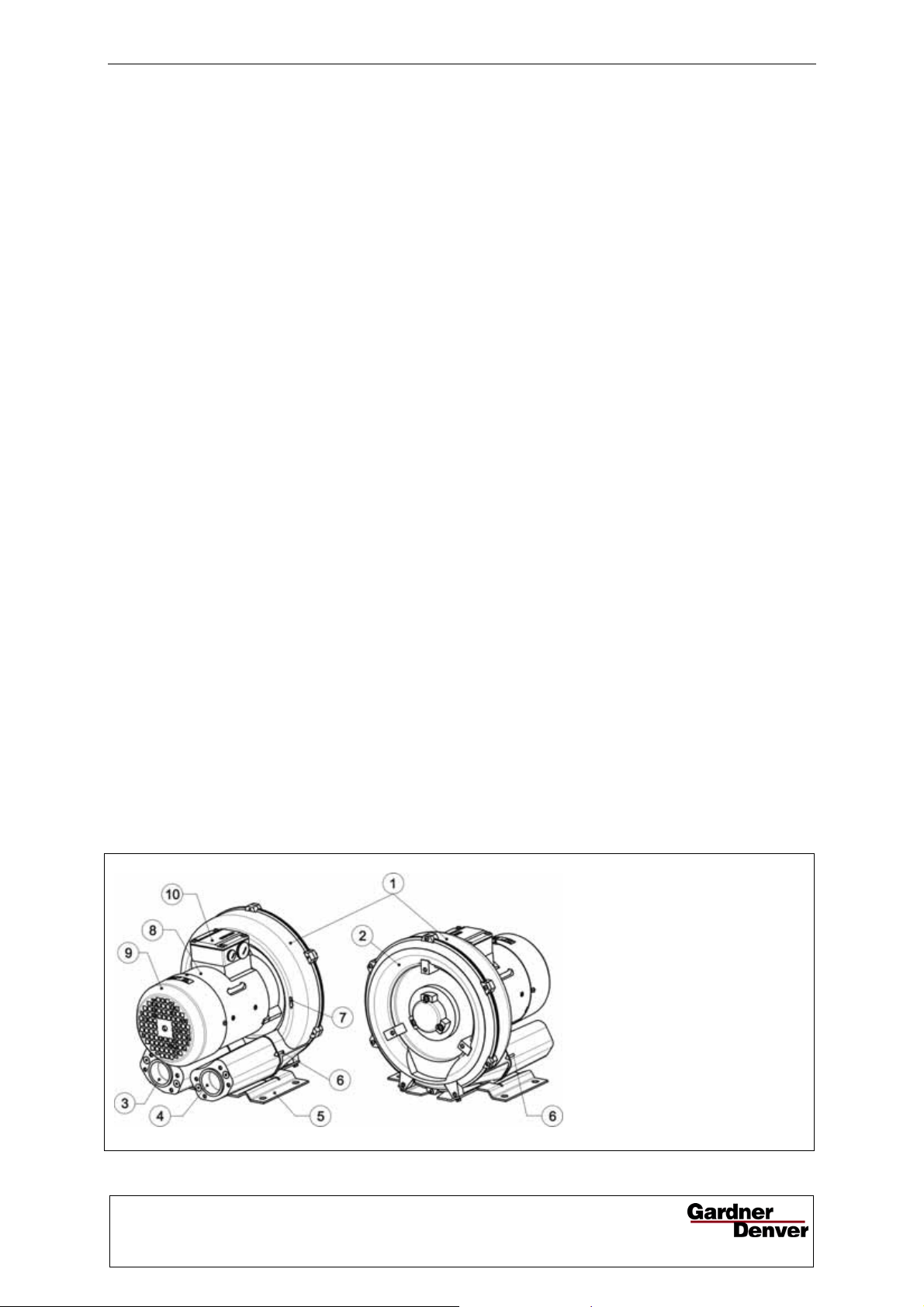
Fig. 1: Design of gas-ring
vacuum
pump/compressor
1 Vacuum pump/compressor
housing
2 Vacuum pump/compressor cover
3 Inlet connection with muffler
4 Discharge connection with
muffler
5 Base
6 Arrow indicating delivery direction
7 Arrow indicating direction of
rotation
8 Drive motor
9 Fan guard (over external fan)
10 Terminal box
© 2011 Gardner Denver Deutschland GmbH · Industriestraße 26 · 97616 Bad Neustadt · Germany
Replication, distribution and / or editing of this document and the use and distribution of its content is
prohibited unless explicitly permitted. Violation obligates compensation for damages.
All rights reserved in case of the issue of a patent, utility patent or design patent.
Page 3
1 Safety
Safety
CAUTION
1.1 Definitions
To point out dangers and important information,
the following signal words and symbols are used
in these operating instructions:
1.1.1 Safety alert symbol
The safety alert symbol is located in the
safety precautions in the highlighted heading field
on the left next to the signal word (DANGER,
WARNING, CAUTION).
Safety precautions with a safety alert symbol
indicate a danger of injuries.
Be sure to follow these safety precautions to
protect against injuries or death!
Safety precautions without a safety alert symbol
indicate a danger of damage.
1.1.2 Signal words
DANGER
The signal words are located in
the safety precautions in the
WARNING
CAUTION
NOTICE
NOTE
highlighted heading field.
They follow a certain hierarchy
and indicate (in conjunction with
the safety alert symbol, see
Chapter 1.1.1) the seriousness
of the danger and the type of
warning.
See the following explanations:
DANGER
Danger of injuries.
Indicates an imminently hazardous situation,
that will result in death or serious injury if the
corresponding measures are not taken.
WARNING
Danger of injuries.
Indicates a potentially hazardous situation, that
could result in death or serious injury if the
corresponding measures are not taken.
CAUTION
Danger of injuries.
Indicates a potentially hazardous situation, that
may result in minor or moderate injury if the
corresponding measures are not taken.
Danger of damage.
Indicates a potentially hazardous situation that
may result in property damage if the
corresponding measures are not taken.
NOTICE
Indicates a possible disadvantage, i.e.
undesirable conditions or consequences can
occur if the corresponding measures are not
taken.
NOTE
Indicates a possible advantage if the
corresponding measures are taken; tip.
1.2 General safety precautions
WARNING
Improper use of the unit can result in serious
or even fatal injuries!
These operating instructions
must have been read completely and
understood before beginning any work with
or at the pump-motor unit,
must be strictly observed,
must be available at the operating location of
the pump-motor unit.
WARNING
Improper use of the unit can result in serious
or even fatal injuries!
Only operate the pump-motor unit
for the purposes indicated under "Intended
Use"!
with the fluids indicated under 'Intended Use'!
with the values indicated under 'Technical
Data'!
WARNING
Improper use of the unit can result in serious
or even fatal injuries!
All work on and with the pump-motor unit
(transport, installation, operation, shut-down,
maintenance, disposal) may only be carried out
by trained, reliable expert personnel!
© Gardner Denver Deutschland GmbH 3 / 32 610.44434.40.000
Page 4
Safety
WARNING
When working on the unit, there is a danger
of injury, e.g. in the form of cuts/cutting off,
crushing and burns!
During all work on and with the pump-motor unit
(transport, installation, operation, shut-down,
maintenance, disposal) wear personal safety
equipment (safety helmet, protective gloves,
safety shoes)!
WARNING
Hair and clothing can be pulled into the unit
or caught and wound up moving parts!
Do not wear long, loose hair or wide, loose
clothes! Use a hair net!
DANGER
Electrical danger!
Work on electrical installations may be carried
out by trained and authorized electricians only!
DANGER
Electrical danger!
Before beginning work on the unit or system, the
following measures must be carried out:
Deenergize.
Secure against being switched on again.
Determine whether deenergized.
Ground and short-circuit.
Cover or block off adjacent energized parts.
DANGER
Electrical danger!
Do not open the motor terminal box until
absence of electricity has been ensured!
WARNING
Danger due to vacuum and gauge pressure:
sudden escape of fluids (skin and eye
injuries),
sudden drawing in of hair and clothing!
Danger due to escaping fluid: Burns!
Use mounting elements, connections, lines,
fittings and containers with sufficient freedom
from leaks and strength for the pressures which
occur.
Check the mounting elements, connections,
lines, fittings and containers for strength, leaks
and firm seating at regular intervals!
WARNING
Danger from rotating parts (external fan,
impeller, shaft):
Cutting/cutting off of extremities,
Grasping/winding up of hair and clothing!
Danger due to vacuum and gauge pressure:
sudden escape of fluids (skin and eye
injuries), sudden drawing in of hair and
clothing!
Danger due to escaping fluid: Burns!
Start-up
and operation only under the following
conditions:
The pump-motor unit must be completely
assembled. When doing so, pay particular
attention to the following components:
– the vacuum pump/compressor cover,
– the muffler on inlet and discharge
connections,
– the fan guard.
The pipes/hoses must be connected to inlet
and discharge connections.
Inlet and discharge connections and the
connected pipes/hoses may not be closed,
clogged or soiled.
Check the mounting elements, connections
of the pipe/hose connections, lines, fittings
and containers for strength, leaks and firm
seating at regular intervals.
WARNING
Danger from rotating parts (external fan,
impeller, shaft):
Cutting/cutting off of extremities,
Grasping/winding up of hair and clo thing!
Danger due to vacuum and gauge pressure:
sudden escape of fluids (skin and ey e
injuries), sudden drawing in of hair and
clothing!
Danger due to escaping fluid: Burns!
Before beginning work on the pump-motor unit
,
take the following measures:
Shut down pump-motor unit and secure
against being switched on again.
Attach a sign on the system controller and on
the control elements for the pump-motor unit:
"DANGER! Maintenance work on vacuum
pump/compressor! Do not switch on!"
Wait for pump-motor unit to come to a
complete stop. Observe run-on time!
Allow pump-motor unit to cool!
Shut-off lines. Release pressure.
Make sure that no vacuum or gauge pressure
is present in the lines/tanks to be opened.
Make sure that no fluids can escape.
610.44434.40.000 4 / 32 © Gardner Denver Deutschland GmbH
Page 5

Safety
WARNING
Danger from rotating impeller:
Cutting/cutting of off extremities!
The rotating impeller is accessible with the inlet
and discharge connections open!
Do not reach into the unit through open
connections!
Do not insert objects into the unit through the
openings!
WARNING
Danger from rotating impeller:
Cutting/cutting of off extremities!
The rotating impeller is accessible with the inlet
and discharge connections open!
With free entry and exit of gases, i.e. with direct
intake out of or direct feeding into the
atmosphere without piping, the following
therefore applies:
Provide the inlet and discharge connections of
the pump-motor unit either with additional
mufflers or with additional piping of a sufficient
length to prevent access to the impeller!
WARNING
Danger of burns from hot surfaces of the
pump-motor unit and from hot fluids!
High temperatures of up to approx. 160°C
Danger zone:
Fan guard
Hazard:
Long, loose hair can be drawn into external fan
through fan guard grate, even with fan guard
mounted!
Protective measures:
Wear hair net!
Danger zone:
Missing or defective muffler inlet or discharge
connection.
Hazard:
Possible serious hearing damage due to emitted
noise.
Protective measures:
Have missing or defective mufflers replaced.
Conduct a noise measurement in the system
after installing the pump-motor unit. The
following measures can be taken from 85 dB(A)
and must be taken from 90 dB(A):
Mark noise area with a warning sign.
Wear hearing protection.
WARNING
WARNING
WARNING
[320°F] can occur on the surface of the pumpmotor unit.
Cover the pump-motor unit with a suitable touch
protection (e.g. perforated plate cover or wire
cover). Do not touch during operation!
Allow to cool after shut-down!
1.3 Residual risks
Danger zone:
Environment of pump-motor unit.
Hazard:
Possible serious hearing damage due to emitted
noise.
Protective measures:
Conduct a noise measurement in the system
during operation after installing the pump-motor
unit.
WARNING
Danger zone:
Hot surface up to approx. 160°C [320°F].
Hazard:
Possible burns.
Protective measures:
Cover the pump-motor unit with a suitable touch
protection (e.g. perforated plate cover or wire
cover).
The following measures can be taken from
85 dB(A) and must be taken from 90 dB(A):
Mark noise area with a warning sign.
Wear hearing protection.
With free entry and exit of gases, i.e. with
direct intake out of or direct feeding into the
atmosphere without piping, attach an
additional muffler.
© Gardner Denver Deutschland GmbH 5 / 32 610.44434.40.000
Page 6

Intended Use
2 Intended Use
This operating manual
is intended for side channel compressors of
the
G-BH1 and G-BH9 series, types 2BH1 1
2BH1 2 2BH1 3 2BH1 4 2BH1 5 2BH1 6
2BH1 8 2BH1 9 2BH9 23,
contains instructions bearing on transport and
handling, installation, commissioning,
operation, shut-down, storage, servicing and
disposal of the G-BH1,G-BH9,
must be completely read and understood by
all operating and servicing personnel before
beginning to work with or on the G-BH1,
G-BH9,
must be strictly observed,
must be available at the site of operation of
the G-BH1, G-BH9.
About the operating and servicing personnel
of the G-BH1, G-BH9
These persons must be trained and
authorized for the work to be carried out.
Work on electrical installations may be carried
out by trained and authorized electricians
only.
The G-BH1,G-BH9
are pump-motor units for generating vacuum
or gauge pressure;
are used to extract, pump and compress
the following gases:
– Air,
– Non-flammable, non-aggressive, non-toxic
and non-explosive gases or gas-air
mixtures.
– With differing gases/gas-air mixtures,
inquire with the Service Department.
are equipped with one of the following kind of
drive motors:
– 3-phase AC drive motor
with a standard or explosion-protected
design
– Single-phase AC drive motor
are intended for industrial applications,
are designed for continuous operation.
With increased switch-on frequency (6x per
hour with equal pauses and operating times)
or with increased gas inflow and ambient
temperature, the excess temperature limit of
the coil and the bearing can be exceeded.
Consult the manufacturer when using under
such conditions.
When operating the G-BH1, G-BH9 the limits
listed in Chapter 3, "Technical Data", Pg. 7 ff.
must always be complied with.
Foreseeable Misuse
It is prohibited
to use the G-BH1, G-BH9 in applications other
than industrial applications unless the
necessary protection is provided on the
system, e.g. guards suitable for children's
fingers;
to use the device in rooms in which explosive
gases can occur if the G-BH1, G-BH9 is not
expressly intended for this purpose;
to extract, to deliver and to compress
explosive, flammable, corrosive or toxic fluids,
unless the G-BH1, G-BH9 is specifically
designed for this purpose;
to operate the G-BH1 with values other than
those specified in Chapter 3, "Technical
Data", Pg. 7 ff.
Any unauthorized modifications of the G-BH1,
G-BH9 are prohibited for safety reasons.
The operator is only permitted to perform the
maintenance and service work described in these
operating instructions.
Maintenance and servicing work which goes
beyond this may only be carried out by
companies which have been authorised by the
manufacturer (ask the service department for
details).
These operating instructions apply only to
pump-motor units with a standard design.
For an explosion-protected design (EEx e II),
see the separate operating instructions.
610.44434.40.000 6 / 32 © Gardner Denver Deutschland GmbH
Page 7
Technical Data
3 Technical Data
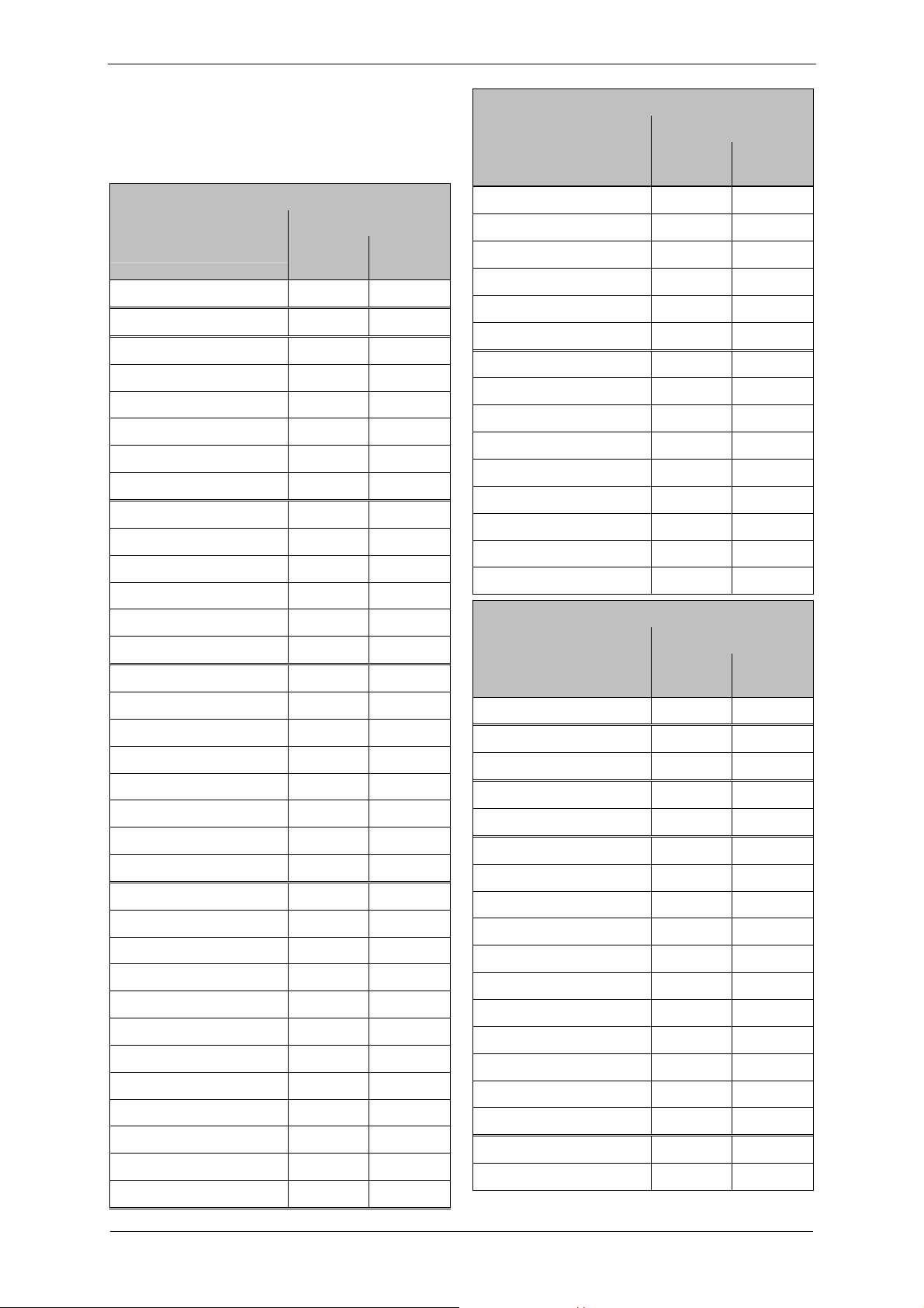
3.1 Mechanical data
Weight
Single-impeller design
Weight
Type [kg]
approx.
2BH1100-7..0. 9 20
[lbs]
approx.
Single-impeller design
Weight
Type [kg]
approx.
[lbs]
approx.
2BH180.-7..0. 117 258
2BH180.-7..1. 126 278
2BH180.-7..2. 132 291
2BH183.-7..0. 120 265
2BH183.-7..1. 129 284
2BH1200-7..0. 9 20
2BH183.-7..2. 135 298
2BH1300-7..0. 9 20
2BH190.-7..0. 179 395
2BH1300-7..1. 10 22
2BH190.-7..1. 198 437
2BH1300-7..2. 11 24
2BH190.-7..3. 210 463
2BH1330-7..0. 10 22
2BH193.-7..0. 179 395
2BH1330-7..1. 11 24
2BH193.-7..1. 198 437
2BH1330-7..2. 12 26
2BH193.-7..3. 209 463
2BH1400-7..0. 13 29
2BH1400-7..1. 16 35
2BH1400-7..2. 17 37
2BH1430-7..0. 14 31
2BH1430-7..1. 17 37
2BH1430-7..2. 18 40
2BH1500-7..0. 20 44
2BH1500-7..1. 22 49
2BH1500-7..2. 23 51
2BH1500-7..3. 25 55
2BH1530-7..0. 21 46
2BH1530-7..1. 23 51
2BH1530-7..2. 24 53
2BH1530-7..3. 26 57
2BH1600-7..0. 27 60
2BH1600-7..1. 30 66
2BH1600-7..2. 36 79
2BH1600-7..3. 40 88
2BH1600-7..6. 32 71
2BH1600-7..7. 39 86
2BH1630-7..0. 29 64
2BH1630-7..1. 32 71
2BH1630-7..2. 37 82
2BH1630-7..3. 43 95
2BH1630-7..6. 34 75
2BH923..-…P 167 368
2BH923..-…Q 145 320
2BH923..-…H 151 333
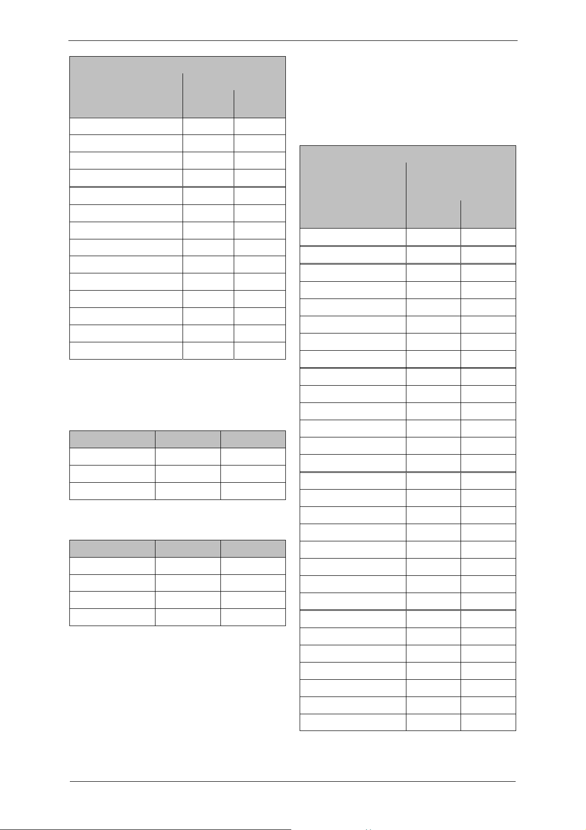
Two-impeller design
Weight
Type [kg]
approx.
[lbs]
approx.
2BH1310-7..2. 15 33
2BH1410-7..3. 25 55
2BH1410-7..4. 27 60
2BH1510-7..4. 40 88
2BH1510-7..5. 44 97
2BH1610-7..1. 43 95
2BH1610-7..2. 48 106
2BH1610-7..3. 54 119
2BH1610-7..4. 66 146
2BH1610-7..5. 73 161
2BH1610-7..7. 50 110
2BH1610-7..8. 62 137
2BH1640-7..3. 54 119
2BH1640-7..4. 69 152
2BH1640-7..5. 75 165
2BH1640-7..8. 62 137
2BH181.-7..1. 171 377
2BH181.-7..2. 177 390
2BH1630-7..7. 40 88
© Gardner Denver Deutschland GmbH 7 / 32 610.44434.40.000
Page 8
Technical Data
Two-impeller design
Weight
Type [kg]
approx.
[lbs]
approx.
2BH181.-7..3. 203 448
2BH181.-7..4. 215 474
2BH184.-7..2. 177 390
2BH184.-7..3. 203 448
2BH191.-7..1. 274 604
2BH191.-7..2. 288 635
2BH191.-7..3. 299 659
2BH191.-7..4. 309 681
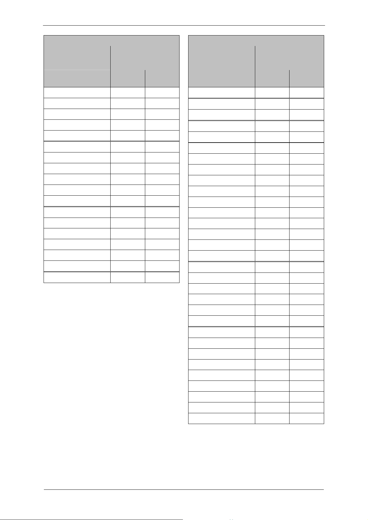
Noise level
Measuring-surface sound-pressure level as per
EN ISO 3744, measured at a distance of 1 m
[3.28 ft] at an operating point of approximately
2/3 of the permissible total pressure difference
with the lines connected without a vacuum or
pressure relief valve, tolerance 3 dB (A).
Single-impeller design
Type 1-m measuring-surface
sound pressure level
L [dB (A)]
50 Hz
approx.
60 Hz
approx.
2BH1100-7..0. 52 55
2BH1200-7..0. 57 61
2BH1940-7B.2. 275 606
2BH1300-7..0. 53 56
2BH1940-7B.3. 314 692
2BH1300-7..1. 53 56
2BH1940-7B.4. 324 714
2BH1300-7..2. 53 56
2BH1943-7..2. 330 728
2BH1330-7..0. 53 56
2BH1943-7..3. 339 747
2BH1330-7..1. 53 56
2BH1943-7..4. 349 769
Minimum distances
Minimum distance to fan guard (for sucking in
cooling air):
Type [mm] [inches]
2BH1 1.. - 2BH1 4 34 1.34
2BH1 5.. - 2BH1 9 53 2.09
2BH923… 52 2.05
Minimum distance to face of vacuum
pump/compressor cover:
Type [mm] [inches]
2BH1 1.. - 2BH1 5 20 0.79
2BH1 6.. 30 1.18
2BH1 8.. - 2BH1 9 40 1.57
2BH923.. 52 2.05
2BH1330-7..2. 53 56
2BH1400-7..0. 63 64
2BH1400-7..1. 63 64
2BH1400-7..2. 63 64
2BH1430-7..0. 63 64
2BH1430-7..1. 63 64
2BH1430-7..2. 63 64
2BH1500-7..0. 64 70
2BH1500-7..1. 64 70
2BH1500-7..2. 64 70
2BH1500-7..3. 64 70
2BH1530-7..0. 64 70
2BH1530-7..1. 64 70
2BH1530-7..2. 64 70
2BH1530-7..3. 64 70
2BH1600-7..0. 69 72
2BH1600-7..1. 69 72
2BH1600-7..2. 69 72
2BH1600-7..3. 69 72
2BH1600-7..6. 69 72
2BH1600-7..7. 69 72
2BH1630-7..0. 69 72
610.44434.40.000 8 / 32 © Gardner Denver Deutschland GmbH
Page 9
Technical Data
Single-impeller design
Type 1-m measuring-surface
Two-impeller design
Type 1-m measuring-surface
sound pressure level
L [dB (A)]
50 Hz
approx.
60 Hz
approx.
2BH1630-7..1. 69 72
2BH1630-7..2. 69 72
2BH1630-7..3. 69 72
2BH1630-7..6. 69 72
2BH1630-7..7. 69 72
2BH180.-7..0. 70 74
2BH180.-7..1. 70 74
2BH180.-7..2. 70 74
2BH183.-7..0. 70 74
2BH183.-7..1. 70 74
2BH183.-7..2. 70 74
2BH190.-7..0. 74 79
2BH190.-7..1. 74 79
2BH190.-7..3. 74 79
2BH193.-7..0. 75 80
2BH193.-7..1. 75 80
2BH193.-7..3. 75 80
2BH923.. 79 81
2BH1310-7..2. 55 61
2BH1410-7..3. 66 69
2BH1410-7..4. 66 69
2BH1510-7..4. 72 74
2BH1510-7..5. 72 74
2BH1610-7..1. 73 76
2BH1610-7..2. 73 76
2BH1610-7..3. 73 76
2BH1610-7..4. 73 76
2BH1610-7..5. 73 76
2BH1610-7..7. 73 76
2BH1610-7..8. 73 76
2BH1640-7..3. 74 78
2BH1640-7..4. 74 78
2BH1640-7..5. 74 78
2BH1640-7..8. 74 ---
2BH181.-7..1. 74 ---
2BH181.-7..2. 74 78
2BH181.-7..3. 74 78
sound pressure level
L [dB (A)]
50 Hz
approx.
60 Hz
approx.
2BH181.-7..4. 74 78
2BH184.-7..2. 74 78
2BH184.-7..3. 74 78
2BH191.-7..1. 74 84
2BH191.-7..2. 74 84
2BH191.-7..3. 74 84
2BH1940-7B.2. 75 84
2BH1940-7B.3. 75 84
2BH1940-7B.4. 75 84
2BH1943-7..2. 75 84
2BH1943-7..3. 75 84
2BH1943-7..4. 75 84
© Gardner Denver Deutschland GmbH 9 / 32 610.44434.40.000
Page 10
Technical Data
Sound power level
Sound power level L
as per EN ISO 3744,
W
tolerance 3 dB (A).
Two-impeller design
Sound power level LW
[dB (A)]
Type 50 Hz 60 Hz
2BH191. - 98
2BH1940 - 98
2BH1943 - 99
2BH923.. - 93
Thread [Nm] [ft lbs]
M12x1,5 4 - 6 2.95 - 4.43
M16x1,5 5 - 7.5 3.69 - 5.53
M25x1,5 6 - 9 4.43 - 6.64
M32x1,5
M40x1,5
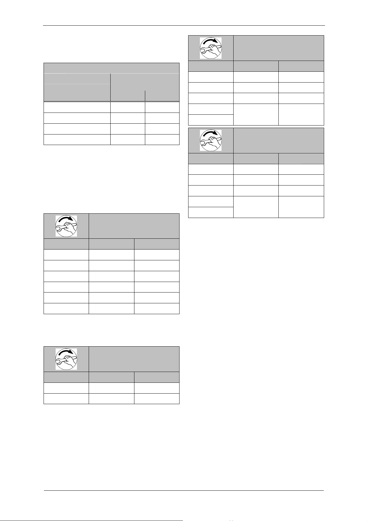
Tightening torques for screw connections
The following values apply if no other information
is available.
With non-electrical connections, property classes
of 8.8 and 8 or higher as per ISO 898-1 are
assumed.
Tightening torques for
non-electrical connections
Thread [Nm] [ft lbs]
M4 2.7 - 3.3 1.99 - 4.44
M5 3.6 - 4.4 2.65 - 3.25
M6 7.2 - 8.8 5.31 - 6.5
M8 21.6 - 26.4 15.9 - 19.5
M10 37.8 - 46.2 27.9 - 34.1
M12 63.0 - 77.0 46.5 - 56.8
The following information for electrical connection
applies to all terminal board connections with the
exception of terminal strips.
Tightening torques for
electrical connections
Thread [Nm] [ft lbs]
Thread [Nm] [ft lbs]
M12x1,5 2 - 3.5 1.48 - 2.58
M16x1,5 3 - 4 2.21 - 2.95
M25x1,5 4 - 5 2.95 - 3.69
M32x1,5
M40x1,5
M4 0.8 - 1.2 0.59 - 0.89
M5 1.8 - 2.5 1.33 - 1.84
Especially for metal and plastic threaded cable
glands and pipe unions, the following values
apply:
Tightening torques for metal
threaded glands/unions
8 - 12 5.9 - 8.85
Tightening torques for plastic
threaded glands/unions
5 - 7 3.69 - 5.16
610.44434.40.000 10 / 32 © Gardner Denver Deutschland GmbH
Page 11

3.2 Electrical data
Technical Data
Installation altitude
See rating plate.
3.3 Operating conditions
Temperatures
Temperature of
pumped gases:
max. permissible temperature:
+40°C [+104°F]
Nominal value:
+15°C [+59°F]
Pump-motor units for higher fluid
temperatures on request.
Ambient
temperature:
max. permissible temperature:
+40°C [+104°F]
min. permissible temperature:
-15°C [+5°F]
Nominal value:
+25°C [+77°F]
Ambient temperatures between
25°C [+77°F] and 40°C [+104°F]
affect the permissible total
pressure difference.
At higher temperatures the winding
may be damaged and the grease
change interval may be shortened.
Pressures
Min. suction pressure: See rating plate
Max. discharge pressure
See rating plate
in compressor mode:
* The total pressure difference, shown on the
rating plate, applies only for the following
conditions:
Ambient temperature: 25°C
Pressure for vacuum operation:
1013 mbar at pressure connection;
Pressure for compressor operation:
1013 mbar at suction connection;
Intake temperature (temperature of conveyed
gases at suction connection): 15°C
For ambient temperatures between 25°C and
40°C, the total pressure difference specified
on the rating plate must be reduced (at 40°C
by 10%).
Consultation with the manufacturer is essential
for such operational conditions.
Max. of 1,000 m [3,280 ft] above sea level.
When installing the pump-motor unit at an altitude of
more than 1,000 m [3,280 ft] above sea level, first
inquire with the Service department.
© Gardner Denver Deutschland GmbH 11 / 32 610.44434.40.000
Page 12

Transport and Handling
4 Transport and Handling
The transport must be carried out in different
ways depending on the type:
WARNING
Tipping or falling can lead to crushing, broken
bones etc.! Sharp edges can cause cuts!
Wear personal safety equipment (gloves, safety
shoes and protective helmet) during transport!
WARNING
Danger from tipping or falling loads!
Prior to transport and handling make sure that
all components are securely assembled and
secure or remove all components the fasteners
of which have been loosened!
Manual handling:
WARNING
Danger from lifting heavy loads!
Manual handling of the unit is only permitted
within the following limits:
max. 30 kg [max. 66 lbs] for men
max. 10 kg [max. 22 lbs] for women
max. 5 kg [max. 11 lbs] for pregnant women
For the weight of the pump-motor unit, see
Chapter 3.1, "Mechanical data",
Section "Weight", Pg. 7. For weights above the
given values use suitable lifting appliances and
handling equipment!
Handling by means of lifting equipment:
WARNING
Danger from tipping or falling loads!
When transporting with lifting equipment,
observe the following basic rules:
Before each transport, check the tight fit of
the eye bolt/lifting attachment, see
"Tightening torques for screw connections",
p. 10.
The lifting capacity of lifting equipment and
lifting gear must be at least equal to the unit's
weight. For the weight of the pump-motor
unit, see Chapter 3.1, "Mechanical data",
Section "Weight", Pg. 7.
The pump-motor unit must be secured so
that it cannot tip or fall.
Do not stand or walk under suspended loads!
2BH11., 2BH12., 2BH13., 2BH14., 2BH15.
(single-impeller): Manual handling
2BH15. (two-impeller), 2BH16., 2BH18.,
2BH19., 2BH923…
Transport with crane, hooked onto eye
bolt/lifting attachment (1 attachment point)
2BH1943:
Transport with crane, hooked with lifting belts
onto eye bolt and onto the holes in the two
feet of the vacuum pump/compressor housing
(3 attachment points).
For transport with a crane, the pump-motor unit
can be hooked into the crane hook as follows:
directly on the eye bolt/lifting attachment
(With 2BH194 the eye bolt and the two foot
holes should be used)
or possibly
with lifting belts.
Eye bolt/lifting attachment:
Types with a weight of up to 30 kg [66 lbs] are
not equipped with an eye bolt/lifting attachment
(2BH11., 2BH12., 2BH13., 2BH14., 2BH15
[single-impeller]).
Types with a weight of more than 30 kg [66 lbs]
are equipped with an eye bolt/lifting attachment
as standard (2BH15. [two-impeller], 2BH16.,
2BH18., 2BH19., 2BH9…).
The eye bolt/lifting attachment is mounted on the
vacuum pump/compressor housing.
In case of possible removal and remounting of
the eye bolt, it must be ensured that the eye level
is positioned exactly in the axis direction of the
pump-motor unit. Lay shims under the eye bolt if
necessary.
The eye bolt/lifting attachment must be firmly
tightened.
Loads laterally to the ring level are not
permissible. Heavy impact loads during transport
must be avoided.
610.44434.40.000 12 / 32 © Gardner Denver Deutschland GmbH
Page 13

5 Installation
WARNING
Installation
WARNING
Improper use of the unit can result in serious
or even fatal injuries!
Have you read the safety precautions in Chapter
1, "Safety", Pg. 3 f.?
Otherwise you many not carry out any work with
or on the pump-motor unit!
DANGER
Danger from missing view into area of pumpmotor unit!
When operating the control elements without a
view into the area of the pump-motor unit, there
is a danger that the pump-motor unit will be
switched on while other persons are still
performing work on it. Extreme injuries are
possible!
Provide control elements at a location with a
view of the pump-motor unit.
DANGER
Electrical danger!
The pump-motor unit must be installed so that
the electrical device cannot be damaged by
external influences!
In particular, the feed pipes must be securely
routed, e.g. in cable ducts, in the floor etc.
WARNING
Danger from balance damage caused by
vibration!
Vibrating environments can cause balance
damage!
Install the pump-motor unit on a solid foundation
or on a solid mounting surface.
Check screw glands/unions for mounting the
pump-motor unit on the mounting surface
regularly for strength and firm seating.
WARNING
Danger from crushing due to pump-motor
unit tipping over!
Wear personal safety equipment (protective
gloves and safety shoes). Handle the unit with
the appropriate care. Install the pump-motor unit
on a solid foundation or on a solid mounting
surface! Check screw glands/unions for
mounting the pump-motor unit on the mounting
surface regularly for strength.
Danger of fire from flammable substances!
The pump-motor unit must never come into
contact with flammable substances.
WARNING
Danger of burns from hot surfaces of the
pump-motor unit and from hot fluids!
High temperatures of up to approx. 160°C
[320°F] can occur on the surface of the pumpmotor unit.
The pump-motor unit must be installed so that
accidental touch of its surface is not possible.
Cover the pump-motor unit with a suitable touch
protection (e.g. perforated plate cover or wire
cover).
WARNING
Danger of injuries from flying parts!
Select installation so that parts that are thrown
out through the grate if the external fan breaks
cannot hit persons!
CAUTION
Danger of tripping and falling!
Make sure the unit does not present a danger of
tripping. Lay cables and pipes so that they
cannot be reached during operation(recessed in
floor, in ducts on the wall etc.).
CAUTION
Danger of overheating due to hot surface of
pump-motor unit!
High temperatures can occur on the surface of
the pump-motor unit.
Temperature sensitive parts, such as lines or
electronic components, may not come into
contact with the surface of the pump-motor unit.
The pump-motor unit is ready to connect on
delivery. However, if the time from delivery to
commissioning of the pump-motor unit exceeds a
certain period, the lubrication of the rolling
bearings must be renewed.
See Chapter 8.2, "Storage conditions",
Section "Lubrication of rolling bearings after
longer storage", Pg. 24 for information on this
topic.
© Gardner Denver Deutschland GmbH 13 / 32 610.44434.40.000
Page 14

Installation
Carry out the following work to install the pumpmotor unit:
Installation and securing,
Attachment of the included loose muffler if
necessary,
Attachment of threaded flange or hose flange
(available as accessories)
for the connection of inlet or discharge pipe to
the muffler,
Electrical connection,
Connection of inlet and discharge connection
to the system.
5.1 Installation
WARNING
For an installation that differs from the following
specifications, it is necessary to inquire with the
Service Department!
Ambient conditions:
The pump-motor unit is suitable for installation in
the following environments:
In a dusty or damp environment,
in buildings,
in the open.
When properly installed in the open, the
pump-motor unit must be protected from
exposure to intensive sunlight, e.g. by
attaching a protective roof. Otherwise, no
special protective devices against the effects
of weathering are required.
The drive motors of the pump-motor units have
the following design:
with degree of protection IP55 (see rating
plate),
with tropicalized insulation.
Installation conditions:
The pump-motor unit must be installed as
follows:
on level surfaces,
at a maximum height of 1000 m [3280 ft]
above sea level.
When installing at an altitude of more than
1,000 m [3,280 ft] above sea level, first inquire
with the Service Department.
Minimum distances:
To ensure sufficient cooling of the pump-motor
unit, it is absolutely necessary that the required
minimum distances to the fan guard and to the
face of the vacuum pump/compressor cover
be maintained. see Chapter 3.1, "Mechanical
data", Section "Minimum distances", Pg. 8.
The minimum distances to the face of the
vacuum pump/compressor cover are especially
important when installing on the vacuum
pump/compressor cover or near a wall.
CAUTION
To ensure sufficient cooling of the pump-motor
unit, also observe the following:
Ventilation screens and openings must
remain clear.
Discharge air of other units may not be
directly sucked in again!
Noise radiation:
To reduce the noise radiation, the following must
be observed:
Do not mount pump-motor unit on noise-
conducting or noise-radiating parts (e.g. thin
walls or sheet-metal plates).
Provide pump-motor unit with sound-
insulating intermediate layers (e.g. rubber
buffers under the base of the pump-motor
unit) if necessary.
Install the pump-motor unit on a stable
foundation or on a rigid mounting surface.
This provides for smooth, low-vibration
running of the pump-motor unit.
Components for reducing noise on the pumpmotor unit:
Mufflers (included as standard equipment):
On delivery the pump-motor units are
equipped with attached mufflers as standard.
The noise radiation is considerably reduced
by the mufflers. See Fig. 2 to Fig. 9, Pg. 18 ff.
Additional silencer (available as an
accessory for the 2BH1):
The additional mufflers enable a further noise
reduction. They may only be used with free
entry and exit of gases, i.e. with direct intake
out of or direct feeding into the atmosphere
without piping.
610.44434.40.000 14 / 32 © Gardner Denver Deutschland GmbH
Page 15

Installation
Sound protection hood (available as an
accessory for the 2BH1):
Noise protection hoods are suitable for
installation in rooms and in the open. They
reduce both the total sound pressure level
and tonal components that are perceived as
particularly annoying.
Installation variants/axis position:
Basically, when installing the pump-motor unit,
the following variants are possible with a different
axis position (horizontal or vertical):
Horizontal installation
Vertical installation on the vacuum
pump/compressor cover ("cover installation")
Vertical mounting on the wall
Basically, all variants are possible with all type.
Exceptions
Vertical axis mounting on the wall with the
compressor cover pointing downward
For vertical axis mounting of the unit on the wall,
the unit is fastened using the holes in the foot.
The foot of the unit has fastening holes.
Place the unit with the foot to the wall on a
base plate with sufficient load-bearing
capability in the mounting position.
Screw the foot of the unit to the wall using
suitable screws.
All fastening holes must have screws!
Remove the base plate.
Eye bolt/lifting attachment:
After set-up, the eye bolt/lifting attachment can
be removed.
5.2 Electrical connection (motor)
For the 2BH1943, vertical axis mounting on
the compressor cover ("cover position") is
necessary.
For the 2BH923, only horizontal axis mounting
and vertical axis mounting on the compressor
cover are possible.
For units with condensate water opening,
horizontal axis mounting with a foot below is
necessary.
Horizontal axis mounting
The foot of the unit has fastening holes.
Electrical danger!
Malpractice can result in severe injuries and
material damage!
Electrical danger!
The electrical connection may be carried out by
trained and authorized electricians only!
DANGER
DANGER
DANGER
Screw the foot of the unit to the base using
suitable screws.
All fastening holes must have screws!
Vertical axis mounting on the compressor
cover ("cover position")
For vertical axis mounting on the compressor
cover, use spring elements.
Spring elements are available as accessories
and come in a set of 3. The upper part has a
threaded stud and the lower part a threaded hole.
fFastening spring elements to the unit:
Screw threaded studs of the spring elements
into the holes on the front side of the
compressor cover and tighten.
Fastening the unit with spring elements to the
foundation:
Select suitable fastening elements for the
threaded hole.
Screw spring elements over the threaded hole
into the base or foundation.
Electrical danger!
Before beginning work on the unit or system, the
following measures must be carried out:
Deenergize.
Secure against being switched on again.
Determine whether deenergized.
Ground and short-circuit.
Cover or block off adjacent energized parts.
CAUTION
Incorrect connection of the motor can lead to
serious damage to the unit!
Regulations:
The electrical connection must be carried out as
follows:
according to the applicable national and local
laws and regulations,
according to the applicable system-dependent
prescriptions and requirements,
according to the applicable regulations of the
utility company.
© Gardner Denver Deutschland GmbH 15 / 32 610.44434.40.000
Page 16

Installation
Electrical power supply:
Observe the rating plate.
It is imperative that the operating conditions
correspond to the data given on the rating plate!
Deviations permissible without reduction in
performance:
±5 % voltage deviation
±2 % frequency deviation
Connection to drive-motor terminal box:
Open the required cable entry openings on the
terminal box. Here the following two cases are
differentiated:
The cable entry opening is prefabricated and
provided with a sealing plug.
Screw out sealing plug.
OR
The cable entry opening is closed off with a
casting skin (only on pump-motor units with
The electrical connection must be carried out as
follows:
The electrical connection must be
permanently safe.
There may be no protruding wire ends.
Clearance between bare live parts and
between bare live parts and ground: ≥ 5.5 mm
[0.217"] (at a nominal voltage of U
≤ 690V).
N
For the tightening torques for terminal board
connections (except terminal strips), see
Chapter 3.1, "Mechanical data",
Section "Tightening torques for screw
connections", Pg. 10.
For terminals with clamping straps (e.g. as per
DIN 46282), the conductors must be inserted
so that approximately the same clamping
height results on both sides of the bar.
Individual conductors must therefore be bent
into a U-shape or connected with a cable lug
(DIN 46234).
drive-motor axis heights of 100 to 160 in
standard design).
Break out casting skin using a suitable tool.
For example, use a metal pin with a
corresponding diameter or a chisel and
hammer.
This also applies to:
the protective conductor,
the outer ground conductor.
Both conductors can be recognized from their
color (green/yellow).
CAUTION
When pounding out the casting skin on the
cable entry openings in the terminal box, the
terminal box or its parts can be damaged (e.g.
terminal board, cable connections).
Proceed with suitable caution and precision
when doing so! Prevent flash formation!
Mount cable glands on the terminal box. Proceed
as follows:
Select one cable gland in each case which is
suitable for the cable diameter.
Insert this cable gland in the opening of the
DANGER
Electrical danger!
The terminal box must be free from
foreign bodies,
dirt,
humidity.
Terminal box cover and cable entries must be
tightly closed so as to make them dustproof and
waterproof. Check for tightness at regular
intervals.
DANGER
terminal box.
Use a reducer if necessary.
Screw on the cable gland so that no moisture,
dirt etc. can penetrate into the terminal box.
Carry out the connection and the arrangement of
the jumpers in accordance with the circuit
diagram in the terminal box.
Connect the protective conductor to the terminal
with the following symbol:
.
610.44434.40.000 16 / 32 © Gardner Denver Deutschland GmbH
Electrical danger!
Clearance between bare live parts and between
bare live parts and ground:
at least 5.5 mm [0.217"] (at a nominal voltage
of U
≤ 690V).
N
There may be no protruding wire ends!
Page 17

Installation
For motor overload protection:
Use motor circuit breakers.
This must be adjusted to the specified
nominal current (see rating plate).
DANGER
Electrical danger!
There is danger of an electrical shock when a
defective pump-motor unit is touched!
Mount motor circuit breaker.
Have electrical equipment checked regularly by
an electrician.
Interference immunity of drive motor:
For drive motors with integrated sensors, the
operator must provide for a sufficient interference
immunity itself. Select a suitable sensor signal
cable (e.g. with screening, connection as for a
motor power-supply cable) and analyzing unit.
Operation with frequency converter:
WARNING
Pump-motor units with a UL approbation may
not be operated on frequency converters in the
US without testing by a suitable test agency!
With a power supply by a frequency converter,
the following must be observed:
High-frequency current and voltage harmonics
in the motor supply cables can lead to emitted
electromagnetic interference. This is
dependent on the converter design (type,
manufacturer, interference suppression
measures).
Be sure to observe the EMC notes of the
converter manufacturer!
Use screened power supply cables if
necessary. For optimal screening, the screen
must be conductively connected over a large
area to the metal terminal box of the drive
motor with a screwed metal gland.
In the case of drive motors with integrated
sensors (e.g. PTC thermistors) interference
voltage can occur on the sensor cable
depending on the converter type.
Limit speed:
see specifications on the rating plate.
© Gardner Denver Deutschland GmbH 17 / 32 610.44434.40.000
Page 18

Installation
5.3 Connecting pipes/hoses (vacuum
pump/compressor)
Mufflers:
The pump-motor units are delivered with mufflers
(indicated with arrows in the following
illustrations) for the inlet and discharge
connections as standard equipment.
On delivery the mufflers are already mounted on
the following pump-motor units.
Fig. 6: 2BH1840-7L... (two-impeller pump-motor
unit with double-flow design)
Fig. 2: 2BH1… (single-impeller pump-motor
units), 2BH9 23
Fig. 3: 2BH1640 (two-impeller pump-motor unit
with double-flow design)
Fig. 4: 2BH1840-7G... (two-impeller pump-motor
unit with double-flow design)
Fig. 7: 2BH1943 (two-impeller pump-motor unit
with double-flow design)
On two-impeller pump-motor units with a twostage design of the types 2BH1310 to
2BH1910 the discharge-side muffler is included
loose for packing-related reasons and must be
mounted by the customer.
Fig. 8: 2BH1310 ... 2BH1610, 2BH1910
(two-impeller pump-motor units with a twostage design)
Fig. 9: 2BH1810 (two-impeller pump-motor unit
with a two-stage design)
Fig. 5: 2BH1840-7J... (two-impeller pump-motor
610.44434.40.000 18 / 32 © Gardner Denver Deutschland GmbH
unit with double-flow design)
Page 19

Installation
WARNING
Danger from rotating impeller:
Cutting/cutting of off extremities!
The rotating impeller is accessible with the inlet
and discharge connections open!
With free entry and exit of gases, i.e. with direct
intake out of or direct feeding into the
atmosphere without piping, the following
therefore applies:
Provide the inlet and discharge connections of
the pump-motor unit either with additional
mufflers or with additional piping of a sufficient
length to prevent access to the impeller!
Connections:
To prevent foreign bodies from entering the unit,
all connections are sealed off when delivered. Do
not remove the sealing plugs until immediately
before connecting the pipes/hoses.
The following applies for the arrangement of the
pipe/hose connections:
The pumped gases are sucked in via the inlet
connection (see Chapter 5.3.1, Pg. 19) and
discharged via the discharge connection
(see
Chapter 5.3.2, Pg. 19).
The shaft rotating direction is marked with an
arrow on the back of the vacuum
pump/compressor housing (Fig. 1, Pg. 2, Item 7).
The delivery direction of the gases is marked
with arrows on both connections (Fig. 1, Pg. 2,
Item 6).
WARNING
Danger from interchanging inlet and
pressure line!
Interchanged inlet and pressure lines can lead
to damage to the pump-motor unit and the
system, and as a result of this to serious
injuries!
Make sure that the inlet and pressure line
cannot be confused when connecting.
Look for the clear marking with the arrow
indicating the delivery direction on the inlet and
discharge connections.
WARNING
Danger due to vacuum and gauge pressure!
Danger due to escaping fluid!
During operation, connected pipes and vessels
are vacuumized or pressurized!
Use only mounting elements, connections, lines,
fittings and containers with sufficient freedom
from leaks and strength for the pressures which
occur.
Make sure that the mounting elements and
connections are mounted sufficiently firmly and
leak-free!
CAUTION
If the pumped gases are passed on on the
discharge side in a closed pipe system, then it
must be ensured that the pipe system is
adapted to the maximum discharge pressure.
See Chapter 3.3: "Operating conditions",
Section "Pressures", Pg. 11. Connect a
pressure relief valve upstream if necessary.
NOTICE
Attach pipes/hoses free of mechanical tensions.
Support the weight of the pipes/hoses.
5.3.1 Inlet connection
The inlet connection with the related muffler
(Fig. 1, Pg. 2, Item 3) is marked with an arrow
pointing into the vacuum pump/compressor.
Connect the inlet pipe here. The pumped gases
are sucked in via this.
Procedure: see Chapter 5.3.3.
WARNING
Danger from solid bodies and impurities in
the pump-motor unit!
If solid bodies penetrate into the pump-motor
unit, blades of the impellers can break and
broken pieces can be thrown out.
Install a filter in the inlet pipe.
Replace filter regularly!
5.3.2 Discharge connection
The discharge connection with the related muffler
(Fig. 1, Pg. 2, Item 4) is marked with an arrow
pointing out of the vacuum pump/compressor.
Connect the discharge pipe here. The pumped
gases are discharged via this. Procedure: see
Chapter 5.3.3.
© Gardner Denver Deutschland GmbH 19 / 32 610.44434.40.000
Page 20

Installation
5.3.3 Procedure when connecting
pipes/hoses
Attach the pipes/hoses to the unit as described in the
following. The pipes/hoses are connected differently to
inlet and discharge connections depending on the
muffler design and the type of line (pipe or hose):
Muffler with inside threads:
The pipe is screwed directly into the muffler.
Muffler without inside thread:
– Screw threaded flange (available as an
accessory) onto the muffler.
– Screw the pipe into the threaded flange.
Hose connection:
– for 2BH1 Screw the hose flange (available
as an accessory) onto the silencer.
– Push the hose onto the hose flange and secure
it with a hose clamp. See Chapter 3.1,
"Mechanical data", Section "Tightening torques
for screw connections", Pg. 10 for information on
this topic.
610.44434.40.000 20 / 32 © Gardner Denver Deutschland GmbH
Page 21

6 Commissioning
WARNING
Improper use of the unit can result in serious or
even fatal injuries!
Have you read the safety precautions in Chapter 1,
"Safety", Pg. 3 f.? Otherwise you many not carry
out any work with or on the pump-motor unit!
WARNING
Danger from rotating parts (external fan, impeller,
shaft): Cutting/cutting o ff of extremities,
Grasping/winding up of hair and clothing!
Danger due to vacuum and gauge p ressure:
sudden escape of fluids (ski n and eye injuries),
sudden drawing in of hair and clothing!
Danger due to escaping fluid: Burns!
Start-up
and operation only under the following conditions:
The pump-motor unit must be completely
assembled. When doing so, pay particular
attention to the following components:
– the vacuum pump/compressor cover,
– the muffler on inlet and discharge
connections,
– the fan guard.
The pipes/hoses must be connected to inlet
and discharge connections.
Inlet and discharge connections and the
connected pipes/hoses may not be closed,
clogged or soiled.
Check the mounting elements, connections
of the pipe/hose connections, lines, fittings
and containers for strength, leaks and firm
seating at regular intervals.
Commissioning
6.1 Preparation
WARNING
Danger from closed connections!
With closed/soiled intake or discharge
connections vacuum or gauge pressure results
in the pump-motor unit.
This can overheat and damage the drive motor
winding.
Before start-up, make sure that the inlet and
discharge connections are not closed, clogged
or soiled!
CAUTION
Before starting up again after a longer standstill:
Measure the insulation resistance of the motor.
With values ≤ 1 kΩ per volt of nominal voltage,
the winding is too dry.
Measures before start-up:
If a shut-off device is installed in the discharge
pipe:
Make sure that the unit is NOT operated with
the shut-off device closed.
Before starting up the pump-motor unit,
observe the values specified on the rating
plate. Specifications on the drive-motor
nominal current apply at a gas entry and
ambient temperature of +40° C [104°F].
Adjust the motor circuit breaker to the drive-
motor nominal current.
Check direction of rotation:
The intended rotating direction of the shaft is
marked with arrows on the vacuum
pump/compressor housing (Fig. 1, Pg. 2,
Item. 7).
The gas delivery direction is marked with
arrows on the inlet and discharge connections
(Fig. 1, Pg. 2, Item 6).
Make sure the pipes/hoses on the inlet and
discharge connections are properly
connected.
Switch the pump-motor unit on briefly and
then off again.
Compare the actual rotating direction of the
external fan with the intended shaft rotating
direction indicated with the arrows shortly
before the pump-motor unit comes to a
standstill.
If necessary, reverse the direction of rotation
of the motor.
© Gardner Denver Deutschland GmbH 21 / 32 610.44434.40.000
Page 22

Commissioning
WARNING
Danger due to rotating parts! Danger due to
vacuum and gauge pressure! Danger due to
escaping fluid!
Test runs may also only be conducted with the
pump-motor unit completely mounted.
DANGER
6.2 Start-up and shut-down
Start-up
Open shut-off device in intake/discharge pipe.
Switch on power supply for drive motor.
Shut-down:
Switch off power supply for drive motor.
Close shut-off device in intake/discharge pipe.
Electrical danger!
The electrical connection may be carried out by
trained and authorized electricians only!
DANGER
Electrical danger!
Before beginning work on the unit or system, the
following measures must be carried out:
Deenergize.
Secure against being switched on again.
Determine whether deenergized.
Ground and short-circuit.
Cover or block off adjacent energized parts.
Check operating speeds:
Observe the operating speed specified on the
rating plate. This may not be exceeded, as
otherwise the noise radiation, vibration behavior,
grease consumption duration and bearing
change interval worsen. To prevent damage as a
result of higher speeds, it may be necessary to
inquire with the Service Department as to the
maximum speed.
WARNING
Danger of hearing damage due to noise
radiation!
For the noise emission of the pump-motor unit
measured by the manufacturer, see Chapter
3.1, "Mechanical data", Section "Noise level",
Pg. 8. However, the actual noise emission
during operation is highly dependent on the
installation and system conditions. Conduct a
noise measurement in the system during
operation after installing the pump-motor unit.
The following measures can be taken from
85 dB(A) and must be taken from 90 dB(A):
Mark noise area with a warning sign.
Wear hearing protection.
With free entry and exit of gases, i.e. with
direct intake out of or direct feeding into the
atmosphere without piping, attach an
additional muffler.
610.44434.40.000 22 / 32 © Gardner Denver Deutschland GmbH
Page 23

7 Operation
Operation
CAUTION
WARNING
Improper use of the unit can result in serious
or even fatal injuries!
Have you read the safety precautions in Chapter
1, "Safety", Pg. 3 f.?
Otherwise you many not carry out any work with
or on the pump-motor unit!
Also be sure to read the safety precautions in
Chapter 6, "Commissioning", Pg. 21!
Starting up and shutting down
See Chapter 6, "Commissioning", SubChapter 6.2, "Start-up and shut-down", Pg. 22.
Also be sure to observe the following important
notes especially for operation:
WARNING
Danger of burns from hot surfaces of the
pump-motor unit and from hot fluids!
High temperatures of up to approx. 160°C
[320°F] can occur on the surface of the pumpmotor unit.
Do not touch during operation!
Allow to cool after shut-down!
CAUTION
Danger of overheating due to hot surface of
pump-motor unit!
High temperatures of up to approx. 160°C
[320°F] can occur on the surface of the pumpmotor unit.
Temperature sensitive parts, such as lines or
electronic components, may not come into
contact with the surface of the pump-motor unit.
CAUTION
Danger of overheating!
During operation the standstill heating may, if
installed, not be switched on!
CAUTION
Danger of rusting due to collection of
condensed water in drive motor area!
On drive motors with closed condensed water
openings:
Remove closures occasionally to allow any
water which has collected to drain off.
Danger of bearing damage!
Heavy mechanical impacts must be avoided
during operating and while at a standstill.
© Gardner Denver Deutschland GmbH 23 / 32 610.44434.40.000
Page 24

Shut-Down and Longer Standstills
8 Shut-Down and Longer Standstills
CAUTION
8.1 Preparing for shut-down or longer
standstill
WARNING
Improper use of the unit can result in serious
or even fatal injuries!
Have you read the safety precautions in Chapter
1, "Safety", Pg. 3 f.?
Otherwise you many not carry out any work with
or on the pump-motor unit!
CAUTION
Danger of rusting due to collection of
condensed water in drive motor area!
On drive motors with closed condensed water
openings:
Remove closures occasionally to allow any
water which has collected to drain off.
CAUTION
Danger of bearing damage!
Avoid mechanical shocks during operation and
shut-down.
Prior to shut-down or longer standstill, proceed
as follows:
Switch off the pump-motor unit.
Close shut-off device in inlet and pressure line
if installed.
Disconnect pump-motor unit from power
supply.
Release pressure.
When doing so, open pipes/hoses slowly and
carefully so that the vacuum or gauge
pressure in the pump-motor unit can be
released.
Remove pipes/hoses.
Provide mufflers on inlet and discharge side
with sealing plugs.
8.2 Storage conditions
To prevent standstill damage during storage, the
environment must provide the following
conditions:
dry,
dust-free,
low-vibration (V
Ambient temperature:
min. -30°C [-22°F]
max. 40°C [+104°F].
≤ 2.8 mm/s [0.11"/sec]).
eff
Danger of overheating due to high
temperature!
When storing in an environment with a
temperature of over 40°C [104°F], the winding
may be damaged and the grease change
interval may be shortened.
Lubrication of rolling bearings after longer
storage:
The new pump-motor unit may at first be stored
following delivery. If the time from deliver to
commissioning exceeds the following periods, the
lubrication of the rolling bearings must be
renewed:
Under advantageous storage conditions
(as specified above): 4 years.
Under disadvantageous storage conditions
(e.g. high humidity, salty air, sandy or dusty
air): 2 years.
In these cases open rolling bearings must be
relubricated and closed rolling bearings must be
completely replaced. In this case be sure to
inquire with the Service Department. In particular,
exact information with regard to the procedure
and grease type are required.
WARNING
Improper use of the unit can result in serious
or even fatal injuries!
All maintenance work on the pump-motor unit
must always be performed by the Service
Department!
Maintenance work on the pump-motor unit may
only be conducted by the operator itself when
the related maintenance manual on hand!
Inquire with the Service Department!
Commissioning after longer standstill:
Before recommissioning after a longer standstill,
measure the insulation resistance of the drive
motor. With values ≤ 1 kΩ per volt of nominal
voltage, the winding is too dry.
610.44434.40.000 24 / 32 © Gardner Denver Deutschland GmbH
Page 25

9 Servicing
WARNING
Improper use of the unit can result in serious
or even fatal injuries!
Have you read the safety precautions in Chapter
1, "Safety", Pg. 3 f.?
Otherwise you many not carry out any work with
or on the pump-motor unit!
WARNING
Improper use of the unit can result in serious
or even fatal injuries!
All maintenance work on the pump-motor unit
must always be performed by the Service
Department!
Maintenance work on the pump-motor unit may
only be conducted by the operator itself when
the related maintenance manual on hand!
Inquire with the Service Department!
9.2 Repairs/troubleshooting
Servicing
9.1 Emptying/Rinsing/Cleaning
Before any maintenance/servicing work, empty,
rinse and clean the outside of the unit.
Empty unit with air and rinse until all residues
have been removed.
Clean the outside of the unit with compressed
air.
– Wear gloves and protective safety glasses.
– Secure the surrounding area.
– Clean the entire surface of the unit and
exterior fan with compressed air.
Fault Cause Remedy Carried
out by
Motor does not
start; no motor
noise.
Motor does not
start; humming
noise..
At least two power
supply leads
interrupted.
One power supply lead
interrupted.
Eliminate interruption by fuses, terminals or
power supply cables.
Eliminate interruption by fuses, terminals or
power supply cables.
Open vacuum pump/compressor cover,
Electrician
Electrician
Service*) Impeller is jammed.
remove foreign body, clean.
Check or correct impeller gap setting if
Service
necessary.
Impeller defective. Replace impeller. Service*)
Rolling bearing on drive
motor side or vacuum
Replace motor bearing or vacuum
pump/compressor bearing.
Service*
pump/compressor side
defective.
Protective motor
switch trips
when motor is
switched on.
Power
consumption too
high.
Winding short-circuit. Have winding checked. Electrician
Reduce throttling. Service*) Motor overloaded.
Throttling does not
match specification on
rating plate.
Compressor is jammed. See fault: "Motor does not start; humming
Clean filters, mufflers and connection pipes if
necessary.
Service*
Service*
noise." with cause: "Impeller is jammed.".
)
)
)
© Gardner Denver Deutschland GmbH 25 / 32 610.44434.40.000
Page 26

Servicing
Fault Cause Remedy Carried
out by
Pump-motor unit
does not
generate any or
generates
insufficient
pressure
difference.
noises.
Abnormal
running noise.
leaky.
Leak in system. Seal leak in the system. Operator
Wrong direction of
rotation.
Incorrect frequency (on
Reverse direction of rotation by interchanging
Electrician
two connecting leads.
Correct frequency. Electrician
pump-motor units with
frequency converter).
Shaft seal defective. Replace shaft seal. Service*)
Different density of
pumped gas.
Change in blade profile
due to soiling.
Flow speed too high. Clean pipes. Use pipe with larger cross-
Take conversion of pressure values into
account. Inquire with Service Department.
Clean impeller, check for wear and replace if
necessary.
Service
Service*
Operator Abnormal flow
section if necessary.
Muffler soiled. Clean muffler inserts, check condition and
Service*
replace if necessary.
Ball bearing lacking
Regrease or replace ball bearing. Service*)
grease or defective.
Seals on muffler
Check muffler seals and replace if necessary. Service*) Compressor
defective.
Seals in motor area
Check motor seals and replace if necessary. Service
defective.
)
)
*) Only when the maintenance manual is at hand: rectification by the operator.
610.44434.40.000 26 / 32 © Gardner Denver Deutschland GmbH
Page 27

9.3 Service/After-sales service
Our Service is available for work (in particular the
installation of spare parts, as well as
maintenance and repair work), not described in
these operating instruction.
A list of spare parts with an exploded drawing is
available on the Internet at
www.gd-elmorietschle.com.
Observe the following when returning pump-
motor unit:
The pump-motor unit must be delivered
complete, i.e. not dismantled.
The pump-motor unit may not present a
danger to the workshop personnel.
Each pump motor unit on delivery to the
workshop must be accompanied with a fully
completed "Statement on health safety and on
the protection of the environment", Pg. 29.
Disposal
10 Disposal
Have the entire pump-motor unit scrapped by a
suitable disposal company. No special measures
are required when doing so.
For additional information on disposing of the
unit, ask the Service Department.
11 Explosion-Protected Design
An additional set of operating instructions with
supplementary or specific information is provided
with these pump-motor units.
The original rating plate of the pump-motor
unit must be properly mounted, intact and
legible.
All warranty claims are voided for pump-motor
units delivered for a damage expertise without
the original rating plate or with a destroyed
original rating plate.
In case of warranty claims, the manufacturer
must be informed of the operating conditions,
operating duration etc. and additional detailed
information provided on request if necessary.
© Gardner Denver Deutschland GmbH 27 / 32 610.44434.40.000
Page 28

EU declaration of conformity
*)
EU declaration of conformity
EU declaration of conformity
Manufacturer:
Gardner Denver Deutschland GmbH
Industriestraße 26
97616 Bad Neustadt
Germany
Responsible for
documentation:
Holger Krause
Industriestraße 26
97616 Bad Neustadt
Germany
Designation:
G series Side channel blower
G-BH1, G-BH9
Types 2BH1 1 2BH1 2 2BH1 3 2BH1 4
2BH1 5 2BH1 6 2BH1 8 2BH1 9
2BH9 23
The side channel blower described above meets the following applicable Community harmonisation
legislation:
2004/108/EC*)
Directive 2004/108/EC of the European Parliament and of the Council of 15 December
2004 on the approximation of the laws of the Member States relating to electromagnetic
compatibility and repealing Directive 89/336/EEC
2006/42/EC
Directive 2006/42/EC of the European Parliament and of the Council of 17 May 2006 on
machinery, and amending Directive 95/16/EC
The protection targets of the directive 2006/95/EC have been met
Harmonised standards applied:
EN 1012-1:2010
EN 1012-2:1996
Compressors and vacuum pumps - Safety requirements - Part 1: Air compressors
Compressors and vacuum pumps - Safety requirements - Part 2: Vacuum pumps
+A1:2009
EN ISO 12100:2010
EN 60204-1:2006
Safety of machinery - General principles for design - Risk assessment and risk reduction
Safety of machinery - Electrical equipment of machines Part 1: General requirements
Bad Neustadt, 26.09.2011
(Place and date of issue)
Thomas Kurth, Managing Director
(Name and function) (Signature)
Only applicable for version with frequency converter 2FC 664.44434.40.000
610.44434.40.000 28 / 32 © Gardner Denver Deutschland GmbH
Page 29

Statement on health safety and on the protection of the environment
Statement on health safety and on the protection of the environment
For the safety of our employees and to comply with statutory requirements on handling substances harmful to the health and
Statement on health safety and on the protection of the environment
the environment, this statement must be enclosed, fully completed, with each unit/system sent.
Without the fully completed statement, repair/disposal is not possible and delays are unavoidable!
The statement is to be completed and signed by suitably qualified, authorised personnel at the operating organisation.
In the case of shipment to Germany, the statement is to be completed in German or English.
The statement is to be attached to the outside of the packing on shipment.
If necessary, the carrier is to be informed.
1. Product designation (type):
2. Serial number (no. BN):
3. Reason for sending:
4. The unit/system
has not come into contact with hazardous substances. There will be no hazards for personnel or the environment during
repair/disposal. Continue with "6. Legally binding statement“
has come into contact with hazardous substances. Continue with "5. Information on the contamination“
5. Information on the contamination
(if necessary provide more information on an additional sheet)
The unit/system was used in the following application:
and has come into contact with the following classifiable substances or substances presenting a hazard to health/environment:
Trade name: Chemical designation:
Hazardous
substance class:
Properties (e.g. toxic, inflammable,
caustic, radioactive):
The unit/system has been emptied in accordance with the operating instructions, flushed and cleaned externally.
Safety data sheets in accordance with the applicable regulations are enclosed ( sheet).
The following safety precautions are necessary for handling (e.g. personal protective equipment):
6. Legally binding statement
I herewith guarantee that the details specified are true and complete and that I, as signatory, am in a position to judge that this is
so.
We are aware that we are liable to the contractor for any damages arising from incomplete or incorrect specifications. We are
obliged to indemnify the contractor against claims for damages by third parties arising from incomplete or incorrect specifications.
We are aware that, irrespective of this statement, we are directly liable to third parties - in particular including the contractor's
employees tasked with repair/disposal.
Company/institute:
Name, position: Phone:
Street: Fax:
Post code, city:
Country: Stamp:
Date, signature:
© Gardner Denver Deutschland GmbH 610.00250.40.905
P.O. box 1510 Phone: +49 7622 392 0 E-mail: er.de@gardnerdenver.com 10.2009
97605 Bad Neustadt Fax: +49 7622 392 300 Internet: www.gd-elmorietschle.com English
© Gardner Denver Deutschland GmbH 29 / 32 610.44434.40.000
Page 30

610.44434.40.000 30 / 32 © Gardner Denver Deutschland GmbH
Page 31

© Gardner Denver Deutschland GmbH 31 / 32 610.44434.40.000
Page 32

Elmo Rietschle is a brand of
Gardner Denver‘s Industrial Products
Group and part of Blower Operations.
www.gd-elmorietschle.de
er.de@gardnerdenver.com
Gardner Denver
Schopfheim GmbH
Roggenbachstraße 58
79650 Schopfheim · Deutschland
Tel. +49 7622 392-0
Fax +49 7622 392-300
Gardner Denver
Deutschland GmbH
Industriestraße 26
97616 Bad Neustadt · Deutschland
Tel. +49 9771 6888-0
Fax +49 9771 6888-4000
 Loading...