

Page 1
Edition: 1.1.2010 · BA 705-EN
Original Operating Instructions
F-CEVF (29), (30), (39)
F-CEV 3718-3 (29), (30), (39) / F-CEV 3718-4 (29)
F-Serie
F-Series
Radial
Radial
Page 2

Table of contents
Table of contents
1 Foreword . . . . . . . . . . . . . . . . . . . . . . . . . . . . . . . . . . . . . . . . . . . . . . . . . . . . . . . . . . . . . . . . . . . 4
1.1 Principles . . . . . . . . . . . . . . . . . . . . . . . . . . . . . . . . . . . . . . . . . . . . . . . . . . . . . . . . . . . . . . . . . . . 4
1.2 Target group . . . . . . . . . . . . . . . . . . . . . . . . . . . . . . . . . . . . . . . . . . . . . . . . . . . . . . . . . . . . . . . . . 4
1.3 Supplier documentation and accompanying documents . . . . . . . . . . . . . . . . . . . . . . . . . . . . . . 4
1.4 Abbreviations . . . . . . . . . . . . . . . . . . . . . . . . . . . . . . . . . . . . . . . . . . . . . . . . . . . . . . . . . . . . . . . . 4
1.5 Directives, standards, laws . . . . . . . . . . . . . . . . . . . . . . . . . . . . . . . . . . . . . . . . . . . . . . . . . . . . . 4
1.6 Symbols and meaning . . . . . . . . . . . . . . . . . . . . . . . . . . . . . . . . . . . . . . . . . . . . . . . . . . . . . . . . . 5
1.7 Technical terms and meaning . . . . . . . . . . . . . . . . . . . . . . . . . . . . . . . . . . . . . . . . . . . . . . . . . . . 5
1.8 Copyright . . . . . . . . . . . . . . . . . . . . . . . . . . . . . . . . . . . . . . . . . . . . . . . . . . . . . . . . . . . . . . . . . . . 5
2 Safety . . . . . . . . . . . . . . . . . . . . . . . . . . . . . . . . . . . . . . . . . . . . . . . . . . . . . . . . . . . . . . . . . . . . . 6
2.1 Warning instruction markings . . . . . . . . . . . . . . . . . . . . . . . . . . . . . . . . . . . . . . . . . . . . . . . . . . . 6
2.2 General . . . . . . . . . . . . . . . . . . . . . . . . . . . . . . . . . . . . . . . . . . . . . . . . . . . . . . . . . . . . . . . . . . . . . 6
2.3 Designated use . . . . . . . . . . . . . . . . . . . . . . . . . . . . . . . . . . . . . . . . . . . . . . . . . . . . . . . . . . . . . . 7
2.4 Unacceptable operating modes . . . . . . . . . . . . . . . . . . . . . . . . . . . . . . . . . . . . . . . . . . . . . . . . . . 7
2.5 Personal qualifi cations and training . . . . . . . . . . . . . . . . . . . . . . . . . . . . . . . . . . . . . . . . . . . . . . . 8
2.6 Safety-conscious work . . . . . . . . . . . . . . . . . . . . . . . . . . . . . . . . . . . . . . . . . . . . . . . . . . . . . . . . 8
2.7 Safety notes for the operator . . . . . . . . . . . . . . . . . . . . . . . . . . . . . . . . . . . . . . . . . . . . . . . . . . . . 8
2.8 Safety instructions for installing, commissioning and maintenance . . . . . . . . . . . . . . . . . . . . . . 9
2.9 Guarantee conditions . . . . . . . . . . . . . . . . . . . . . . . . . . . . . . . . . . . . . . . . . . . . . . . . . . . . . . . . . . 9
3 Transport, storage and disposal . . . . . . . . . . . . . . . . . . . . . . . . . . . . . . . . . . . . . . . . . . . . . . . . 10
3.1 Transportation . . . . . . . . . . . . . . . . . . . . . . . . . . . . . . . . . . . . . . . . . . . . . . . . . . . . . . . . . . . . . . . 10
3.1.1 Unpack and check the delivery condition . . . . . . . . . . . . . . . . . . . . . . . . . . . . . . . . . . 10
3.1.2 Lifting and transporting . . . . . . . . . . . . . . . . . . . . . . . . . . . . . . . . . . . . . . . . . . . . . . . . . 10
3.2 Storage . . . . . . . . . . . . . . . . . . . . . . . . . . . . . . . . . . . . . . . . . . . . . . . . . . . . . . . . . . . . . . . . . . . . . 11
3.2.1 Ambient conditions for storage . . . . . . . . . . . . . . . . . . . . . . . . . . . . . . . . . . . . . . . . . . 11
3.3 Disposal . . . . . . . . . . . . . . . . . . . . . . . . . . . . . . . . . . . . . . . . . . . . . . . . . . . . . . . . . . . . . . . . . . . . 11
4 Set up and operation . . . . . . . . . . . . . . . . . . . . . . . . . . . . . . . . . . . . . . . . . . . . . . . . . . . . . . . . . 12
4.1 Setup . . . . . . . . . . . . . . . . . . . . . . . . . . . . . . . . . . . . . . . . . . . . . . . . . . . . . . . . . . . . . . . . . . . . . . 12
4.1.1 Data plate . . . . . . . . . . . . . . . . . . . . . . . . . . . . . . . . . . . . . . . . . . . . . . . . . . . . . . . . . . . 13
4.2 Description . . . . . . . . . . . . . . . . . . . . . . . . . . . . . . . . . . . . . . . . . . . . . . . . . . . . . . . . . . . . . . . . . . 13
4.3 Areas of application . . . . . . . . . . . . . . . . . . . . . . . . . . . . . . . . . . . . . . . . . . . . . . . . . . . . . . . . . . . 13
5 Installation . . . . . . . . . . . . . . . . . . . . . . . . . . . . . . . . . . . . . . . . . . . . . . . . . . . . . . . . . . . . . . . . . 14
5.1 Preparing for installation . . . . . . . . . . . . . . . . . . . . . . . . . . . . . . . . . . . . . . . . . . . . . . . . . . . . . . . 14
5.2 Installation . . . . . . . . . . . . . . . . . . . . . . . . . . . . . . . . . . . . . . . . . . . . . . . . . . . . . . . . . . . . . . . . . . 14
5.3 Connecting suction pipe . . . . . . . . . . . . . . . . . . . . . . . . . . . . . . . . . . . . . . . . . . . . . . . . . . . . . . . 15
5.4 Connecting the motor . . . . . . . . . . . . . . . . . . . . . . . . . . . . . . . . . . . . . . . . . . . . . . . . . . . . . . . . . 15
6 Commissioning and decommissioning . . . . . . . . . . . . . . . . . . . . . . . . . . . . . . . . . . . . . . . . . . 16
6.1 Commissioning . . . . . . . . . . . . . . . . . . . . . . . . . . . . . . . . . . . . . . . . . . . . . . . . . . . . . . . . . . . . . . 16
6.1.1 Checking the rotation direction. . . . . . . . . . . . . . . . . . . . . . . . . . . . . . . . . . . . . . . . . . . 17
6.2 Decommissioning/ storing . . . . . . . . . . . . . . . . . . . . . . . . . . . . . . . . . . . . . . . . . . . . . . . . . . . . . . 17
6.3 Re-commissioning . . . . . . . . . . . . . . . . . . . . . . . . . . . . . . . . . . . . . . . . . . . . . . . . . . . . . . . . . . . . 17
| www.gd-elmorietschle.com © Gardner Denver Schopfheim GmbH, Gardner Denver Deutschland GmbH
2
Page 3

Table of contents
7 Maintenance and repair . . . . . . . . . . . . . . . . . . . . . . . . . . . . . . . . . . . . . . . . . . . . . . . . . . . . . . . 18
7.1 Ensuring operational safety . . . . . . . . . . . . . . . . . . . . . . . . . . . . . . . . . . . . . . . . . . . . . . . . . . . . . 18
7.2 Maintenance work . . . . . . . . . . . . . . . . . . . . . . . . . . . . . . . . . . . . . . . . . . . . . . . . . . . . . . . . . . . . 18
7.2.1 Check and clean fi lter bags . . . . . . . . . . . . . . . . . . . . . . . . . . . . . . . . . . . . . . . . . . . . . 19
7.3 Repair/ Service . . . . . . . . . . . . . . . . . . . . . . . . . . . . . . . . . . . . . . . . . . . . . . . . . . . . . . . . . . . . . . . 20
7.4 Spare parts . . . . . . . . . . . . . . . . . . . . . . . . . . . . . . . . . . . . . . . . . . . . . . . . . . . . . . . . . . . . . . . . . . 21
8 Malfunctions: Causes and elimination . . . . . . . . . . . . . . . . . . . . . . . . . . . . . . . . . . . . . . . . . . . 22
9 Technical Data . . . . . . . . . . . . . . . . . . . . . . . . . . . . . . . . . . . . . . . . . . . . . . . . . . . . . . . . . . . . . . 23
www.gd-elmorietschle.com © Gardner Denver Schopfheim GmbH, Gardner Denver Deutschland GmbH |
3
Page 4
Foreword
1 Foreword
1.1 Principles
These operating instructions:
• are a part of the following radial blower (suction
units) models F-CEVF 3718-3 (29), (30), (39) and
F-CEVF 3718-4 (29).
• describe how to use them safely and properly in
all life phases.
• must be available where the equipment is used.
1.2 Target group
The target group for these instructions is technically
trained specialists.
1.3 Supplier documentation and accompanying documents
Document Contents No.
Operating Instructions BA 705-EN
Supplier documentation
Declaration of Conformit C 0002-EN
Declaration of harmlessness 7.7025.003.17
Spare parts’ list Spare parts’ document E 705
Data sheet Technical data and graphs D 705
Manufacturer’s declaration
EU Directive 2002/95/EG (RoHS)
—
1.4 Abbreviations
Fig. Figure
F-CEVF Radial blower (suction unit)
3
/min Volume fl ow, capacity
m
mbar Pressure difference, static
1.5 Directives, standards, laws
See Conformity Declaration
| www.gd-elmorietschle.com © Gardner Denver Schopfheim GmbH, Gardner Denver Deutschland GmbH
4
Page 5
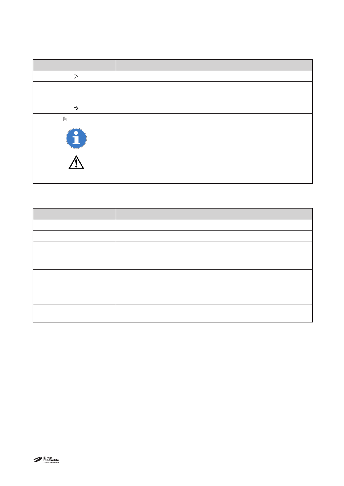
1.6 Symbols and meaning
Symbol Explanation
Condition, pre-requisite
#### Instructions, action
a), b),... Instructions in several steps
Results
Foreword
[-> 14]
Cross reference with page number
Information, note
Safety symbol
Warns of potential risk of injury
Obey all the safety instructions with this symbol in order to avoid injury
and death.
1.7 Technical terms and meaning
Term Explanation
Machine Blower and motor combination ready to be connected
Motor Blower drive motor
Radial blower (suction unit)
Machine for suction operation, high volume fl ow at small differential pressures
Radial Machine’s design or active principle
Volume fl ow
The volume fl ow names how much air or gas volume is conveyed per
time unit of a blower or streams through a pipeline
Pressure difference Pressure difference in opposite to the atmospheric pressure at 1 bar
(abs.) and 20°C
Noise emission
The noise emitted at a specifi c loading given as a fi gure, sound pressure
level dB(A) as per EN ISO 3744.
1.8 Copyright
Passing on or copying this document, using and
providing information on its contents are prohibited
unless expressly permitted.
www.gd-elmorietschle.com © Gardner Denver Schopfheim GmbH, Gardner Denver Deutschland GmbH |
5
Page 6
Safety
2 Safety
The manufacturer is not responsible for damage if
you do not follow all of this documentation.
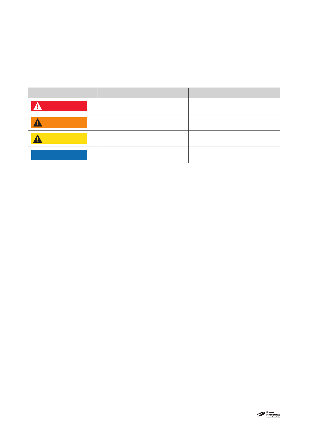
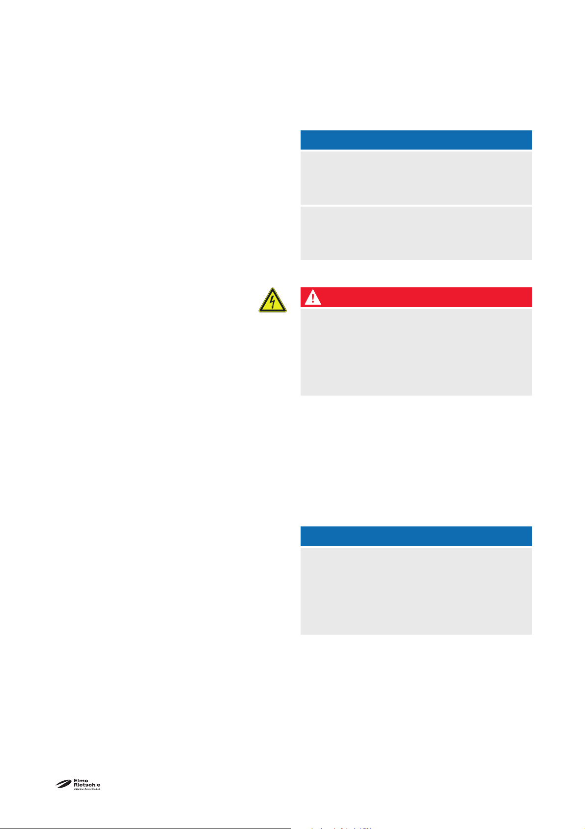
2.1 Warning instruction markings
Warning Danger level Consequences if not obeyed
DANGER
WARNING
CAUTION
NOTICE
2.2 General
immediately imminent danger Death, severe bodily injury
possible imminent danger Death, severe bodily injury
possible hazardous situation Slight bodily injury
possible hazardous situation Material damage
These operating instructions contain basic instructions for installation, commissioning, maintenance
and inspection work which must be obeyed to ensure the safe operation of the machine and prevent
physical and material damage.
The safety instructions in all sections must be taken
into consideration.
The operating instructions must be read by the
responsible technical personnel/ operator before
installing and commissioning and must be fully understood. The contents of the operating instructions
must always be available on site for the technical
personnel / operator. Instructions fi xed directly onto
the machine must be obeyed and must always remain legible. This applies for example to:
• Symbols for connections
• Data and motor data plate
• Instruction and warning plates
The operator is responsible for observing local regulations.
| www.gd-elmorietschle.com © Gardner Denver Schopfheim GmbH, Gardner Denver Deutschland GmbH
6
Page 7

Safety
2.3 Designated use
The machine must only be operated in such areas
as are described in the operating instructions:
• only operate the machine in a technically perfect
condition
• do not operate the machine when it is only partially assembled
• the machine must only be operated at an ambient temperature of between 5 and 40°C, the
temperatures of the media handled may not
exceed 50°C
Please contact us for temperatures outside this
range.
• the machine may convey, compress or extract
the following media:
• convey air with a relative humidity up to 90%
• all non-explosive, non-infl ammable, non-ag-
gressive and non-poisonous dry gases and
gas air mixtures
• units should be used only shortly with a fully
closed inlet or when not connected to a system
2.4 Unacceptable operating modes
• extracting, conveying and compressing explosive, infl ammable, aggressive or poisonous media, e.g. dust as per ATEX zone 20-22, solvents
as well as gaseous oxygen and other oxidants,
water vapour, traces of oil, liquids or solid materials
• using the machine in non-commercial plants if
the necessary precautions and protective measures have not been taken in the plant
• installing in environments that are at risk of explosions
• using the machine in areas with ionising radiation
• modifi cations to the machine and accessories
www.gd-elmorietschle.com © Gardner Denver Schopfheim GmbH, Gardner Denver Deutschland GmbH |
7
Page 8

Safety
2.5 Personal qualifi cations and training
• Ensure that people entrusted with working on
the machine have read and understood these
operating instructions before starting work,
particularly the safety instructions for installation,
commissioning, maintenance and inspection
work.
• Manage the responsibilities, competence and
monitoring of staff
• all work must only be carried out be technical
specialists:
• Installation, commissioning, maintenance
and inspection work
• Working with electricity
• personnel being trained to work on the ma-
chine must be supervised by technical specialists only
2.6 Safety-conscious work
The following safety regulations apply in addition
to the safety instructions and intended use listed in
these instructions:
• Accident prevention regulations, safety and operating regulations
• the standards and laws in force
2.7 Safety notes for the operator
• hot parts of the machine must not be accessible
during operation or must be fi tted with a guard
• eople must not be endangered by the free extraction or discharge of pumped media
• Risks arising from electrical energy must be
eliminated.
| www.gd-elmorietschle.com © Gardner Denver Schopfheim GmbH, Gardner Denver Deutschland GmbH
8
Page 9

Safety
2.8 Safety instructions for installing, commissioning and maintenance
• The operator will ensure that any installation,
commissioning and maintenance work is carried out by authorised, qualifi ed specialists who
have gained suffi cient information by an in-depth
study of the operating instructions.
• Only work on the machine when it is idle and
cannot be switched on again
• Ensure that you follow the procedure for decommissioning the machine described in the operating instructions.
• Fit or start up safety and protective devices
again immediately after fi nishing work. Vor Wiederinbetriebnahme die aufgeführten Punkte für
die Inbetriebnahme beachten
• Conversion work or modifi cations to the machine are only permissible with the manufacturer’s consent.
• Only use original parts or parts approved by the
manufacturer. The use of other parts may invalidate liability for any consequences arising.
• Keep unauthorised people away from the machine
2.9 Guarantee conditions
The manufacturer’s guarantee or warranty will no
longer apply in the following cases:
• Improper use
• Not complying with these instructions
• Operation by insuffi ciently qualifi ed staff
• Using spare parts that have not been approved
by Gardner Denver Schopfheim GmbH
• Unauthorised modifi cations to the machine or
the accessories supplied by Gardner Denver
Schopfheim GmbH
www.gd-elmorietschle.com © Gardner Denver Schopfheim GmbH, Gardner Denver Deutschland GmbH |
9
Page 10

Transport, storage and disposal
3 Transport, storage and disposal
3.1 Transportation
3.1.1 Unpack and check the delivery condition
a) Unpack the machine on receipt and check for
transport damage.
b) Notify the manufacturer of transport damage im-
mediately
c) Dispose of the packaging in accordance with the
local regulations in force.
3.1.2 Lifting and transporting
a) that the machine is secured against tipping and
b) Put the goods to be conveyed on a horizontal
c) The blowers are equipped with rubber feet.
WARNING
Hurt or limbs crushed as a result of the items
being transported falling or tipping over.
When transporting ensure:
falling.
base.
1
Fig. 1 Lifting and transporting
1 Rubber feet
| www.gd-elmorietschle.com © Gardner Denver Schopfheim GmbH, Gardner Denver Deutschland GmbH
10
Page 11

3.2 Storage
Transport, storage and disposal
NOTICE
Material damage caused by improper storage.
Ensure that the storage area meets the following
conditions:
a) dust free
b) vibration free
3.2.1 Ambient conditions for storage
Ambient conditions Value
Relative humidity 0% to 80%
Lagertemperatur -10°C to +60°C
The machine must be stored in a dry environment
with normal air humidity. It should not be stored for
more than 6 months.
3.3 Disposal
WARNING
Danger from infl ammable, corrosive or poisonous substances.
Machines that come into contact with hazardous substances must be decontaminated before
disposal.
When disposing ensure the following::
a) Collect oils and grease separately and dispose
of in accordance with the local regulations in
force.
b) Do not mix solvents, limescale removers and
paint residues
c) Remove components and dispose of them in
accordance with the local regulations in force.
d) Dispose of the machine in accordance with the
national and local regulations in force.
e) Parts subject to wear and tear (marked as such
in the spare parts list) are special waste and
must be disposed of in accordance with the
national and local waste laws.
www.gd-elmorietschle.com © Gardner Denver Schopfheim GmbH, Gardner Denver Deutschland GmbH |
11
Page 12

Set up and operation
4 Set up and operation
4.1 Setup
e
1
A
G
1
Fig. 2 Radial blower (Suction unit) F-CEVF (29)
A Suction connection
B Exhaust air exit
N Data plate
Motor starter
G
1
e
1
h
1
x
1
y
1
BB
N
Filter cover
Filter housing
Clips
Clips
| www.gd-elmorietschle.com © Gardner Denver Schopfheim GmbH, Gardner Denver Deutschland GmbH
12
Page 13

4.1.1 Data plate
Typ CEVF 3718-3 (29)
Y
220/380 V ± 10%
1
Bauj./Nr. 10
1016053110
pmax. - 47 mbar
max. 360 m³/h
2861499
4
5 62 3
3~ Mot.
50 Hz5,40/3,10 AΔ/
Set up and operation
1 Type/ Size (mechanical version)
2 Year of construction
3 Serial number
4 Motor design
5 Item no.
6 Pressure difference
7 Frequency
EN 60034
S1 1,1 kW
2850 min
-1
8 Capacity
9 Current drawn
10 Speed
7
81013
91112
11 Voltage
12 Motor rating
Fig. 3 Data plate
13 Operating mode
4.2 Description
Suction blowers F-CEVF 3718-3 (29), (30), (39) and F-CEVF 3718-4 (29) are multistage radial blowers and
work according to the dynamic compressing principle utilising non contact rotating impellors.
The suction blowers with fi lter housing and dust separator are suitable for vacuum operation. They have one
suction connection (Fig. 2/A). The motor and blower form a very compact unit. A shaft seal is fi tted between
bearing and pumping chamber. The impellors are fi xed onto an extended vertical motor shaft.
Versions (29) and (30) are equipped with a thermal overload motor starter and version (39) is equipped with a
plug in connectors.
4.3 Areas of application
The models F-CEVF 3718-3 (29), (30), (39) and F-CEVF 3718-4 (29) are suitable for removing of paper powder and dust. Liquids may not be handled.
They have capacities upto 5 m
3
/min and obtain a pressure difference of up to 90 mbar. The maximum
vacuum is shown on the data plate (Fig. 2/N). Data sheet D 705 shows the capacity curve for this unit.
If the unit is switched on more frequently (at regular intervals of about 10 times per hour or at higher
ambient temperatures and intake temperatures, the
excess temperature limit of the motor winding and
the bearings may be exceeded.Please contact the
manufacturer should the unit be used under such
conditions.
If it is installed in the open air the unit must be protected from environmental infl uences, (e.g. by a protective roof).
www.gd-elmorietschle.com © Gardner Denver Schopfheim GmbH, Gardner Denver Deutschland GmbH |
13
Page 14

Installation
5 Installation
5.1 Preparing for installation
Check the following points:
• Machine freely accessible from all sides
• Do not close ventilation grids and holes
• Suffi cient room for installing and removing pipes
and for maintenance work, particularly for installing and dismantling the machine
• No external vibration effects
• Do not suck any hot exhaust air from other machines into the cooling system.
When installing the blower make sure there is a space of 0.25 m above the blower to facilitate
removal of fi lter bags (Fig. 4/k). The discharge cooling air exit (Fig. 2/B) should be unrestricted:
5.2 Installation
Ensure that the foundation complies with the follow-
• Even and level
• The bearing surface must be designed to be
It is possible to install the machine on a fi rm base without anchoring. When installing on a substructure we recommend fi xing with fl exible buffers.
NOTICE
We would recommend placing the units on rubber
feet for trouble free operation.
Material damage resulting from the machine
tipping over and falling.
When installed at more than 1000 m above sea
level a reduction in power is noticeable. In this
case we would ask you to contact us.
ing conditions:
able to take the weight of the machine
| www.gd-elmorietschle.com © Gardner Denver Schopfheim GmbH, Gardner Denver Deutschland GmbH
14
Page 15
Installation
5.3 Connecting suction pipe
a) Connect the suction pipe at suction connection
(Fig. 2/A).
NOTICE
Long and/or small bore pipework should be
avoided as this tends to reduce the capacity of
the blower.
The units should be used only shortly with a
fully closed inlet or when not connected to a
system.
5.4 Connecting the motor
DANGER
Danger of death if the electrical installation has
not been done professionally.
The electrical installation must only be done by a
qualifi ed electrician observing EN 60204. The operating company has to provide the main switch.
a) The motor‘s electrical data is given on the data
plate (Fig. 2/N) or on the motor data plate. The
motors comply with DIN EN 60034 and are in
protection class IP 54 and insulation class F.
The motor data must be compared with the
data of the existing mains network (current type,
voltage, network frequency, permitted current
value).
b) Connect the motor utilising the motor starter
(Fig. 2/G
NOTICE
) or the plug in connector.
1
Power supply
The conditions at the installation location must
match the information on the motor data plate.
Without derating the following is permissible:
• ± 5% Voltage deviation
• ± 2% Frequency deviation
www.gd-elmorietschle.com © Gardner Denver Schopfheim GmbH, Gardner Denver Deutschland GmbH |
15
Page 16

Commissioning and decommissioning
6 Commissioning and decommissioning
6.1 Commissioning
WARNING
Improper use
May lead to severe or fatal injuries. Therefore be
sure to obey the safety instructions.
CAUTION
Noise emission
The highest noise pressure levels measured as
per EN ISO 3744 are given in Section 9.
When spending a long time in the vicinity of the
running machine use ear protectors to avoid permanent damage to your hearing.
NOTICE
During operation the fi lter cover (Fig. 2/e1)
must be tightly secured.
| www.gd-elmorietschle.com © Gardner Denver Schopfheim GmbH, Gardner Denver Deutschland GmbH
16
Page 17

6.1.1 Checking the rotation direction
Commissioning and decommissioning
The intended direction of rotation of the drive
shaft is shown by the rotary direction arrow
(Fig. 4/O).
a) Start the motor briefl y (max. two seconds) to
check the direction of rotation. To see the direction of rotation using the aperture (Fig. 4/D). For
this the fi lter housing (Fig. 2/h
) must be remo-
1
ved. Remove clips (Fig. 2/y1), remove fi lter cover
(Fig. 2/e1) complete with fi lter housing (Fig. 2/h1).
When looking at the impeller, it must rotate clockwise.
NOTICE
Incorrect direction of rotation
Running in reverse for a long time may damage the
machine.
Use a phase sequence indicator to check the direction of rotation (anti-clockwise rotating fi eld).
6.2 Decommissioning/ storing
Stop the machine
a) Switch the machine off.
b) If available close the cut off device in the suction
pipe.
c) Disconnect the machine from the electricity
source.
d) Depressurise the machine: Open the pipes
slowly.
The pressure reduces slowly.
e) Remove the pipes and hoses.
f) Seal the connections for suction nozzles using
adhesive foil.
see also Section 3.2.1, Page 11
6.3 Re-commissioning
a) Check the condition of the machine (cleanliness,
cabling etc.).
www.gd-elmorietschle.com © Gardner Denver Schopfheim GmbH, Gardner Denver Deutschland GmbH |
For installation see Section 5 Page 14
For commissioning see Section 6.1 Page 16
17
Page 18

Maintenance and repair
7 Maintenance and repair
7.1 Ensuring operational safety
Regular maintenance work must be carried out in order to ensure operational safety.
Maintenance intervals also depend on the operational demands on the machine.
With any work observe the safety instructions described in Section 2.8 “Safety notes for installation, commissioning and maintenance”.
The whole unit should always be kept in a clean condition.
7.2 Maintenance work
Interval Maintenance to be carried out Section
monthly Check the pipes and screws for leaks and to ensure they are
seated properly and if necessary seal again or tighten up.
DANGER
Danger of death from touching live parts.
Before maintenance work disconnect the machine
by pressing the main switch or unplugging it and
ensure that it cannot be turned on again.
—
monthly Check the terminal box and cable inlet holes for leaks and if
necessary re-seal.
monthly Clean the ventilation slots on the machine and the motor
cooling ribs.
depending on how dirty the
discharged medium is
monthly or depending on how
dirty the discharged medium
is daily
Clean exhaust air slots (Fig. 2/B). —
Check and clean fi lter bags (Fig. 4/k). 7.2.1
—
—
| www.gd-elmorietschle.com © Gardner Denver Schopfheim GmbH, Gardner Denver Deutschland GmbH
18
Page 19

7.2.1 Check and clean fi lter bags
Maintenance and repair
e
1
Fig. 4 Check and clean fi lter bags
O Direction of rotation
D Aperture
k Filter bags
m Motor housing
Filter cover
e
1
Filter housing
h
1
Clips
x
1
y
Clips
1
1
1
Oh
mx
D
y
1
k
Therefore open clips (Fig. 4/x1) and remove fi lter
cover (Fig. 4/e1). Remove fi lter bags (Fig. 4/k), clean
and knock out. After 2 or 3 times cleaning the bags
also check the inside of the fi lter housing (Fig. 4/h1).
Therefore open clips (Fig. 4/y1) and remove fi lter
housing (Fig. 4/h1). Check outlet openings (Fig. 2/B),
inlet openings (Fig. 4/D) and the fi ns on the motor
housing (Fig. 4/m). Clean if required.
www.gd-elmorietschle.com © Gardner Denver Schopfheim GmbH, Gardner Denver Deutschland GmbH |
19
Page 20

Maintenance and repair
7.3 Repair/ Service
a) For on site repair work the motor must be
disconnected from the mains by a qualifi ed
electrician so that it cannot be started up again
accidentally. For repairs use the manufacturer,
its branch offi ces or authorised dealers. Please
contact the manufacturer for the address of the
service centre responsible for you (see Manufacturer‘s address).
NOTICE
For each machine that is sent to an Elmo Rietschle
Service centre for inspection, maintenance or repair, a
fully completed, signed declaration of harmlessness
must be enclosed.
The declaration of harmlessness is part of the
supplier‘s documentation.
Fig. 5 Clearance certifi cate 7.7025.003.17
b) After a repair or re-commissioning, the actions
listed under „Installation“ and „Commissioning“
must be carried out as for initial commissioning.
| www.gd-elmorietschle.com © Gardner Denver Schopfheim GmbH, Gardner Denver Deutschland GmbH
20
Page 21

7.4 Spare parts
Fig. 6 Spare parts list (example)
Maintenance and repair
Order spare parts in accordance with the:
• Spare parts list:
E 705 ➝ F-CEVF 3718-3 (29), (30), (39)
• Download the PDF fi le
http://www.gd-elmorietschle.com
➝ Downloads
➝ Product Documents
➝ F-Series ➝ Spare Parts
• Parts subject to wear and gaskets are indi-
cated separately on the list.
• Web site:
http://www.service-er.de
• Select the type, size and design.
NOTICE
Only use original spare parts or parts approved by
the manufacturer. The use of other parts may lead to
malfunctions and invalidate liability or the guarantee
for any consequences arising.
Fig. 7 Web site
http://www.service-er.de
www.gd-elmorietschle.com © Gardner Denver Schopfheim GmbH, Gardner Denver Deutschland GmbH |
21
Page 22

Malfunctions: Causes and elimination
8 Malfunctions: Causes and elimination
Fault Cause Troubleshooting Important
Machine is
switched off
by the motor
protection
switch
Insuffi cient
suction capacity
Machine gets
too hot
Mains voltage/ Frequency
does not correspond with the
motor data
Check all electrical connections
Motor protection switch is not
set correctly
Blower operates without connection to a system
Filter bags are contaminated
or full
Suction pipe is too long or too
narrow
Machine or system leaking Check the pipework and screw con-
Ambient or intake temperature
is too high
Blower sucks too little air Check the rotation direction resp. cross
Check by qualifi ed electrician Section 5.5
Connect system Section 5.3
Clean or discharge fi lter bags Section 7.2.1
Check the the suction pipe Section 5.3
nections for leaks and to ensure that
they are fi rmly seated
Ensure it is being used properly Section 2.3
sections of the pipes
Section 7.2
Section 6.1.1
Section 5.3
Filter bags are contaminated
or full
Please contact Elmo Rietschle Service for other malfunctions or those that cannot be eliminated.
Clean or discharge fi lter bags Section 7.2.1
| www.gd-elmorietschle.com © Gardner Denver Schopfheim GmbH, Gardner Denver Deutschland GmbH
22
Page 23

Technical Data
9 Technical Data
F-CEVF 3718 (29), (30), (39) 1,1 kW 1,5 kW
Sound pressure level (max.)
EN ISO 3744
Tolerance± 3 dB(A))
dB(A)
50 Hz 75 76
60 Hz 76 77
3718/3 40 -
Weight kg
3718/4 - 44
Diameter mm 474
Width mm 549
3718/3 494
Height mm
3718/4 542
You will fi nd more technical data on the data sheet
D 705
• Download the pdf fi le:
D 705 ➝ F-CEVF 3718-3 + 3718-4 (29)
• Download the pdf fi le:
http://www.gd-elmorietschle.com
➝ Downloads
➝ Product Documents
➝ F-Series ➝ Data Sheets
Fig. 8 Data sheet (example)
ACHTUNG
Subject to technical changes.
www.gd-elmorietschle.com © Gardner Denver Schopfheim GmbH, Gardner Denver Deutschland GmbH |
23
Page 24

Elmo Rietschle is a brand of
Gardner Denver‘s Industrial Products
Division and part of Blower Operations.
www.gd-elmorietschle.com
er.de@gardnerdenver.com
Gardner Denver
Schopfheim GmbH
Roggenbachstraße 58
79650 Schopfheim · Deutschland
Tel. +49 7622 392-0
Fax +49 7622 392-300
Page 25

Hereby the manufacturer
confirms:
EC - declaration of conformity 2006/42/EC
Gardner Denver Schopfheim GmbH
Postfach 1260
D-79642 Schopfheim
that the machine:
of the:
is conform to the regulations of the guideline indicated above.
The following harmonized and national standards and specifications are applied:
EN 1012-1:2010
EN 1012-2:1996+A1:2009 Compressors and vacuum pumps — Safety requirements — Part 2:
Radial blower
Series: F-CEVF
Type: F-CEVF 3718-3, F-CEVF 3718-4
Compressors and vacuum pumps — Safety requirements — Part 1:
Compressors
Vacuum pumps
These declarations of conformity are invalid when the machine has been modified without prior approval by us and the approval has been documented in writing.
Name and address of the EC person in
charge for documentation
Gardner Denver Schopfheim GmbH
Postfach 1260
D-79642 Schopfheim
Gardner Denver Schopfheim GmbH
Schopfheim, 1.8.2011
Dr. Friedrich Justen, Director Engineering
C_0002_EN
Page 26

Safety declaration form
s
.
s
/
A
.
3
S
for vacuum pumps and component
7.7025.003.17
Page 1 of 1
Gardner Denver Schopfheim GmbH
Roggenbachstr. 58, 79650 Schopfheim Phone: +49/(0)7622/392-0 Fax: +49/(0)7622/392-300
Repairs and/or maintenance of vacuum pumps and components will only be carried out if a declaration has been
filled in correctly and completely
.
If not, the repair work cannot be started and delays will result.
This declaration must only be filled in and signed by authorised qualified staff
2. Reason for the submission1. Type of vacuum pumps/ components
Type description:
Machine number
Order number:
Delivery date:
3. Condition of vacuum pumps/ component
4. Contamination of the vacuum pumps
Was this being operated? YES NO components when in use
Which lubrication was used? Toxic YES NO
Corrosive YES NO
Was the pump/ component emptied? Microbiological*) YES NO
(Product/Consumables) YES NO Explosive*) YES NO
Has the pump/ component been cleaned and decontaminaRadioactive*) YES NO
other YES NO
YES
Cleaning agent:
Cleaning method:
*) Microbiological, explosive or radioactively contaminated vacuum pumps/ components will only be accepted
with proof that they have been cleaned properly.
Type of toxic substance or process-related, dangerous reaction products with which the vacuum pumps/
components came into contact:
Trade name, manufacturer's Chemical Hazard
product name name class substances are released accidents
1
2
3
4
Personal protection measures:
ction to be taken if toxic First aid in the event of
Hazardous decomposition products when subjected to thermal load
YES NO
Which?
5. Legally binding declaration
We swear that the information in this declaration is accurate and complete and that I, the undersigned, am in a
position to judge this. We are aware that we are liable to the contractor for damage caused by incomplete and
inaccurate information. We undertake to release the contractor from any damage claims from third parties arising
from incomplete or incorrect information. We are aware that, regardless of this declaration, we are directly liable
to third parties including in particular the contractor's staff entrusted with handling or repairing the product
Company:
Street: Post code/ Town:
Phone: Fax:
Name (in capitals) Position:
Date:
Legally binding signature:
TOS no. / Index: 7.7025.003.17 / 0
Office responsible: G
Company stamp:
File management: ..\7702500317.xl
Gardner Denver Schopfheim GmbH Postfach 1260 D-79642 Schopfheim
 Loading...