

Page 1
Edition 05.2014 · 610.00260.40.000 Original operating instructions · English
Operating Instructions
2FC4...-1ST | 2FC4...-1PB | 2FC4...-1PN |
2FC4...-1SC | 2FC4...-1CB
Page 2

Contents
1 Overview of sizes ......................................................................... 4
2 Further information ...................................................................... 5
2.1 Storing the documentation ............................................................. 5
2.2 Explanation of the terms and symbols ........................................... 5
2.3 Changes in comparison to the previous version ............................ 6
2.4 Other valid documents ................................................................... 6
3 Safety and responsibility ............................................................. 7
3.1 Explanation of warning signs ......................................................... 7
3.2 Safety instructions .......................................................................... 7
3.2.1 General information ........................................................................ 7
3.2.2 Transport and Storage ................................................................... 8
3.2.3 Commissioning ............................................................................... 9
3.2.4 Operation ........................................................................................ 10
3.2.5 Maintenance and inspection .......................................................... 10
3.2.6 Repairs ........................................................................................... 11
3.2.7 Disassembly and Disposal ............................................................. 12
3.3 Correct use of the equipment ........................................................ 12
3.4 Staff qualifications and training ...................................................... 12
3.5 Requirements of the operator ........................................................ 13
4 Product identification ................................................................... 14
4.1 Model description ........................................................................... 14
4.2 Description of the drive control ...................................................... 14
4.3 CE marking ..................................................................................... 14
5 Installation ..................................................................................... 15
5.1 Safety instructions for installation .................................................. 15
5.2 Installation requirements ................................................................ 15
5.2.1 Suitable ambient conditions ........................................................... 15
5.2.2 Suitable installation location for the motor-integrated drive control
......................................................................................................... 16
5.2.3 Basic connection variations ........................................................... 16
5.2.4 Short-circuit and earth-fault protection .......................................... 17
5.2.5 Wiring instructions .......................................................................... 17
5.2.6 Preventing electromagnetic interference ....................................... 18
5.3 Installation of the drive controller integrated in the motor ............. 18
5.3.1 Mechanical installation of sizes A - C ............................................ 18
5.3.2 Mechanical installation of size D .................................................... 20
5.3.3 Power connection of sizes A - C .................................................... 22
5.3.4 Power connection of size D ............................................................ 23
5.3.5 Connections for braking resistor .................................................... 24
5.3.6 Control terminals ............................................................................ 24
5.3.7 Wiring diagram ............................................................................... 25
5.4 Installing the wall-mounted drive controller ................................... 26
5.4.1 Installation location that is suitable for wall mounting ................... 26
5.4.2 Mechanical installation ................................................................... 27
5.4.3 Power connection .......................................................................... 30
5.4.4 Braking chopper ............................................................................. 30
5.4.5 Control terminals ............................................................................ 30
6 Commissioning ............................................................................. 31
6.1 Safety information for commissioning ............................................ 31
6.2 Communication .............................................................................. 32
6.3 Block diagram ................................................................................ 33
610.00260.40.000 · 05.2014
2 / 74
© Gardner Denver Deutschland GmbH
Page 3

A
A
A
A
A
Contents
6.4 Commissioning steps ..................................................................... 34
6.4.1 Start up the integrated drive control .............................................. 34
6.4.2 Commission the drive control wall assembly and replacement ..... 34
7 Parameters .................................................................................... 36
7.1 Safety instructions for handling the parameters ............................ 36
7.2 General information on parameters ................................................ 36
7.2.1 Explanation of operating modes .................................................... 36
7.2.2 Structure of parameter tables ........................................................ 39
7.3
pplication parameter .................................................................... 40
7.3.1 Basic parameters ........................................................................... 40
7.3.2 Fixed frequency .............................................................................. 44
7.3.3 Motor potentiometer ...................................................................... 45
7.3.4 PID process controller .................................................................... 46
7.3.5
nalogue inputs .............................................................................. 47
7.3.6 Digital inputs ................................................................................... 49
7.3.7
nalogue output ............................................................................. 50
7.3.8 Digital outputs ................................................................................ 51
7.3.9 Relay ............................................................................................... 52
7.3.10 External error .................................................................................. 53
7.3.11 Motor current limit .......................................................................... 53
7.3.12 Blocking detection ......................................................................... 54
7.4 Power parameters .......................................................................... 55
7.4.1 Motor data ...................................................................................... 55
7.4.2 I
2
T ................................................................................................... 57
7.4.3 Switching frequency ....................................................................... 57
7.4.4 Controller data ................................................................................ 57
7.4.5 Square-law characteristic ............................................................... 59
7.4.6 Controller data for synchronous motor .......................................... 59
8 Error detection and elimination .................................................. 61
8.1 Display of the LED flash codes for error detection ........................ 61
8.2 List of errors and system errors ..................................................... 62
9 Technical data .............................................................................. 64
9.1 General data ................................................................................... 64
9.2 Derating of output power ............................................................... 65
9.2.1 Derating through increased ambient temperature ......................... 66
9.2.2 Derating due to installation altitude ................................................ 67
9.2.3 Derating due to the clock frequency .............................................. 68
10 Optional accessories ................................................................... 69
10.1
dapter plates ................................................................................ 69
10.2 Hand-held unit MMI, including 3 m connection cable RJ11 to
connector M12 ............................................................................... 71
10.3 PC communication cable USB to connector M12 (RS485/RS232
converter integrated) ...................................................................... 71
11 Guidelines, norms and standards ............................................... 72
11.1 EMC limit classes ........................................................................... 72
11.2 Classification acc. to IEC/EN 61800-3 ........................................... 72
11.3 Standards and guidelines ............................................................... 72
11.4
pproval according to UL .............................................................. 73
© Gardner Denver Deutschland GmbH
3 / 74
05.2014 · 610.00260.40.000
Page 4
1
Overview of sizes
Overview of sizes
1
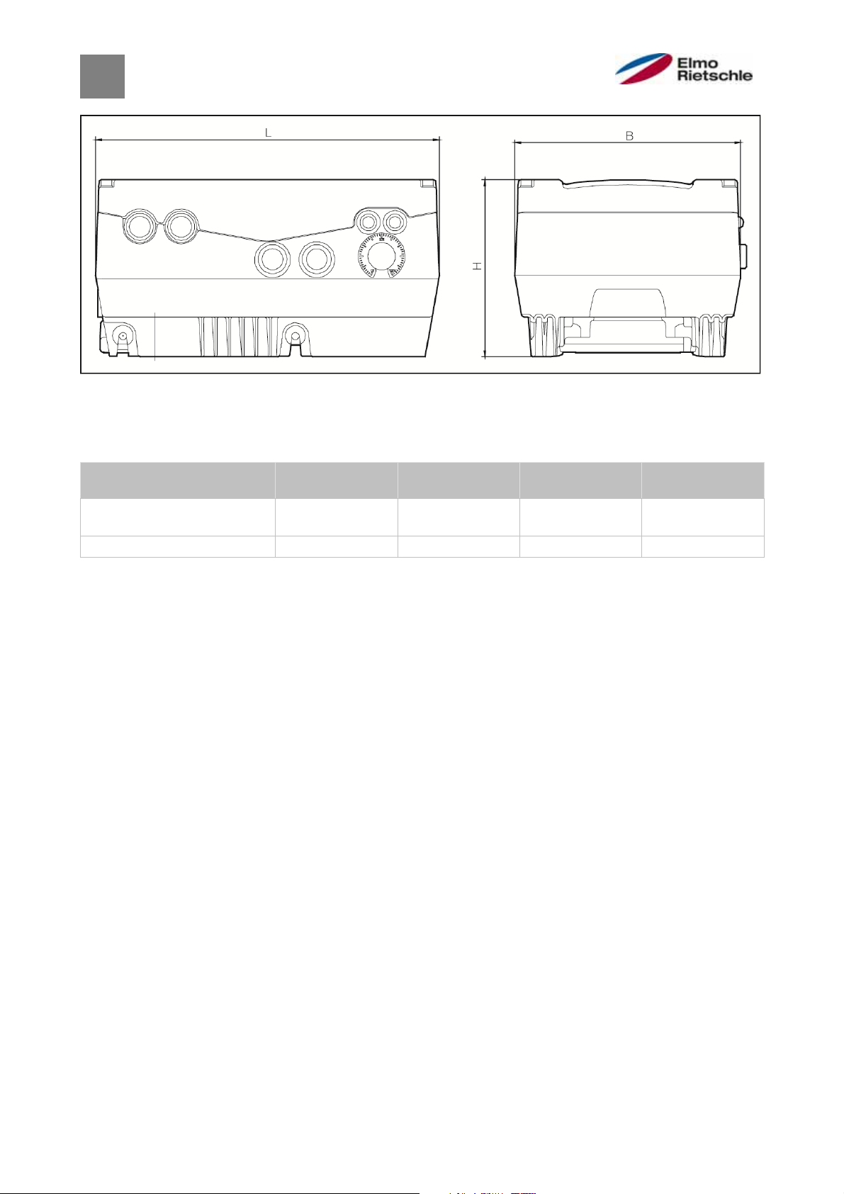
Dimensional drawings
The drive controls are available in the following performance classes with the
specified size names.
Sizes
Sizes drive controls motor
MA MB MC MD
integrated
Recommended motor power
[kW]
Dimensions L x B x H [mm] 233 x 153 x 120 270 x 189 x 140 307 x 223 x 181 414 x 294 x 232
1.5 2.2 / 3.0 / 4.0 5.5 / 7.5 11.0 / 15.0 /
18.5 / 22.0
610.00260.40.000 · 05.2014
4 / 74
© Gardner Denver Deutschland GmbH
Page 5
A
r
2
Further information
Storing the documentation
2.1
Store this manual and all other applicable documents safely so they are available
as and when required.
Provide the operator of the system with this manual so it is available as and when
required.
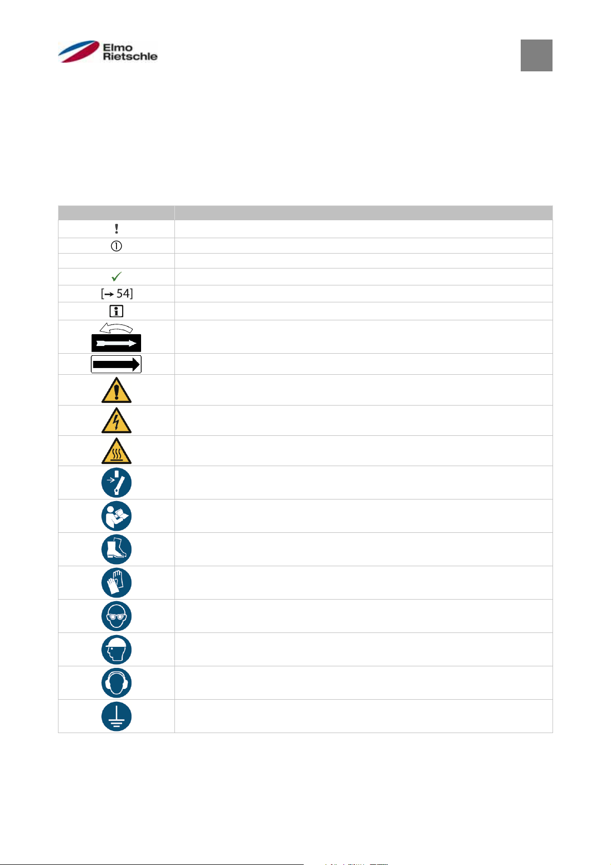
Explanation of the terms and symbols
2.2
In these instructions symbols and terms will be used to mean the following.
Symbol Explanation
Requirement, pre-requisite
One-step handling instructions
1 2 3 Multi-step handling instructions
Result
Cross reference with page reference
dditional information, tips
Direction of rotation arrow
Direction of conveyance arrow
General warning sign (warns of risk of injury)
Electrical voltage warning
Hot surface warning
Disconnect prior to maintenance or repai
Further information
2
Observe the instructions
Use foot protection
Use hand protection
Use eye protection
Use head protection
Use ear protection
Earth prior to use
© Gardner Denver Deutschland GmbH
5 / 74
05.2014 · 610.00260.40.000
Page 6

2
Further information
Term Explanation
Plant Part provided by the user in which the vacuum pump/compressor is installed.
Vacuum
pump/compressor
Ready to connect machine for the generation of a vacuum and/or overpressure.
The vacuum pump/compressor consists of a compressor part and motor, as well
as other accessories where applicable.
Motor Asynchronous motor for driving the vacuum pump/compressor.
Compressor Mechanical part of the vacuum pump/compressor without motor.
Assembly environment Space in which the vacuum pump/compressor is set up and operated (this may
differ from the suction environment).
Drive control Device for rotation speed control of the vacuum pump/compressor. The drive
control can be mounted close to the motor (wall assembly) or integrated into the
vacuum pump/compressor
Changes in comparison to the previous version
2.3
Amendments in comparison to version 02.2014
▪ 2.2 Explanation of the terms and symbols
▪ 5.3.6 Control terminals
Table: Terminal assignment X5 of the standard application card, terminal no. 6
▪ 6.4.1 Start up the integrated drive control
▪ 6.4.2 Commission the drive control wall assembly and replacement
▪ 7.2.1 Explanation of the operating modes
Table: Logic table of fixed frequencies parameter 1,020 deleted
▪ 7.3.1 Basic parameters
Parameter 1,131
Other valid documents
2.4
All instructions that describe the use of the drive control and if applicable, further
instructions of all accessory parts used, e.g.
Document number Purpose
— Vacuum pump/compressor operating ma
610.00260.01.010 *
610.00260.01.020 *
610.00260.01.030 *
Operating manual 2FC4...-1PB OR
Operating manual 2FC4...-1PN OR
Operating manual 2FC4...-1SC OR
610.00260.01.040 * Operating manual 2FC4...-1CB
610.00260.01.600 * MMI hand-held unit operating manual
*according to the model option or accessories
Download of 3D files (.stp) for drive control and adapter plates under www.gdelmorietschle.com.
To parameterise the drive control, the parameter description is ready to be
downloaded (www.gd-elmorietschle.com). The download contains all necessary
information for correct parameterisation.
nual
610.00260.40.000 · 05.2014
6 / 74
© Gardner Denver Deutschland GmbH
Page 7
3
Safety and responsibility
Safety and responsibility
3
The manufacturer is not liable for damage caused by the failure to observe these
instructions and the related documents [➙ 6].
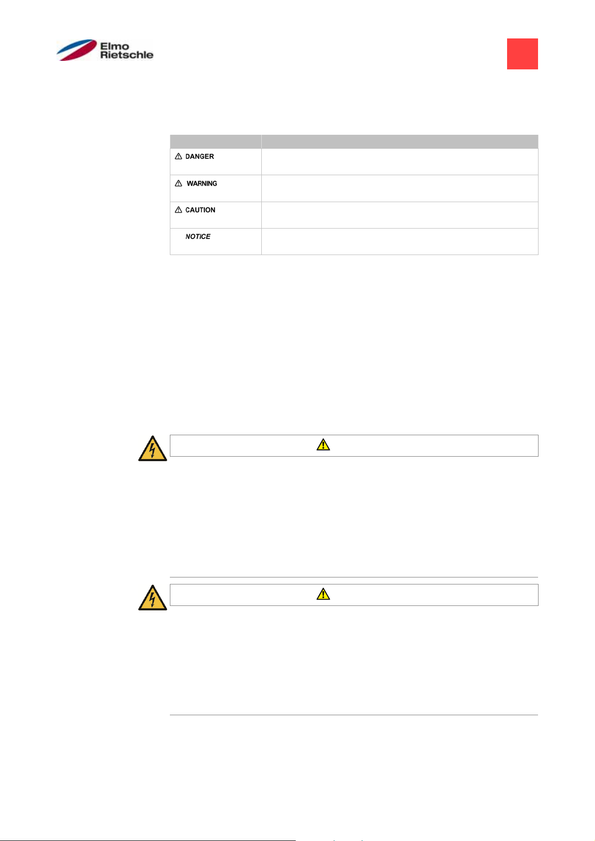
Explanation of warning signs
3.1
Warning sign Explanation
Danger that failure to observe the measures could lead to
death or serious physical injuries.
Danger that failure to observe the measures could lead to
death or serious physical injuries.
Danger that failure to observe the measures could lead to
minor physical injuries.
Danger that failure to observe the measures could lead to
3.2
Safety instructions
material damage.
The following warnings, precautionary measures and comments are provided for
your safety and serve to prevent damage to the drive control and the components
connected to it. This chapter contains warnings and information that are generally
applicable when handling drive controls. They are split into general information,
transport and storage, start-up, operation, repairs and dismantling & disposal.
Specific warnings and comments that apply to specific activities can be found at
the start of the appropriate chapters and are repeated and added to at various
critical points in these chapters.
Please read this information carefully as it is provided for your personal safety and
will also prolong the life of the drive control and connected devices.
3.2.1
General information
WARNING
This drive controller carries dangerous voltages and controls rotating mechanical parts which may be dangerous!
Disregarding the warnings or failure to follow the instructions contained in
this manual may lead to death, serious bodily injury or substantial property
damage.
Only qualified personnel should work on this drive controller. These personnel
must be thoroughly familiar with all safety instructions, installation, operation
and maintenance procedures contained in this manual. The smooth and safe
operation of the drive controller depends on proper handling, installation, operation and maintenance.
WARNING
Risk of fire or electric shock!
Improper use, modifications and the use of spare parts and accessories
that are not sold or recommended by the manufacturer of the drive controller can cause fire, electric shock and bodily injury.
The cooling element of the drive controller and motor can reach temperatures
of above 70°C [158 °F]. During installation, sufficient spacing between adjacent components should be maintained. Before working on the drive controller or motor, required cooling time must be ensured. If necessary, a protection
against accidental contact should be installed.
© Gardner Denver Deutschland GmbH
7 / 74
05.2014 · 610.00260.40.000
Page 8

3
Safety and responsibility
NOTICE
The drive controller may be operated safely only if the required ambient
conditions are met, see Suitable ambient conditions [➙ 15].
NOTICE
This operating manual must be kept in the vicinity of the equipment, so as
to be readily accessible to all users.
NOTICE
Please read these safety instructions and warnings carefully and all the
warning labels attached to the equipment before installing and commissioning. Make sure that the warning labels are kept in a legible condition and
replace missing or damaged labels.
3.2.2
Transport and Storage
NOTICE
Risk of damage to the drive controller!
The drive controller can be damaged in the case of non-compliance with
the instructions and destroyed during subsequent handling.
The smooth and safe operation of this drive controller requires proper mount-
ing, installation and assembly as well as careful operation and maintenance.
The drive controller must be protected during transport and storage against
mechanical shocks and vibration. The protection against excessive temperatures (see Technical data [➙ 64]) must be guaranteed.
610.00260.40.000 · 05.2014
8 / 74
© Gardner Denver Deutschland GmbH
Page 9

3.2.3
Commissioning
Safety and responsibility
3
DANGER
Risk of injury due to electric shock!
The non-observance of warnings can result in severe bodily injury or substantial property damage.
1. Only hard-wired grid connections are permitted. The device must be earthed
(DIN EN 61140; VDE 0140-1).
2. The drive controls may have contact currents > 3.5mA. According to DIN EN
61800-5-1 chapter 4.3.5.5.2, an additional protective earth conductor with the
same cross section as the original earth conductor must be attached. The
possibility of connecting a second protective earth conductor is located underneath the power supply (with marked ground symbol) on the outside of the
device. For the connection, a suitable M6x15 screw (torque: 4.0 Nm
[2.95 ft lbs]) is included in the scope of delivery of the adapter plates.
3. When using alternating current drive controls, conventional FI circuit breakers
of type A, also known as RCDs (residual current-operated protective devices)
are not permitted for the protection of direct or indirect contact! As per DIN
VDE 0160, section 5.5.2 and EN 50178, section 5.2.11.1, the FI circuit breaker
(RCD type B) must be suitable for all types of current.
4. The following terminals can also lead to dangerous voltages when the engine
is at a standstill:
the mains connection terminals X1: L1, L2, L3
the motor connection terminals X2: U, V, W
the connection terminals X6, X7: Relay contacts relays 1 and 2
the PTC connection terminals T1/T2
5. When using different voltage levels (e.g. +24V/230V), always ensure that lines
do not cross! Furthermore, the operator must ensure that the applicable regulations are adhered to (e.g. doubled or reinforced insulation according to DIN
EN 61800-5-1).
6. The drive control contains electrostatically sensitive assemblies. These assemblies can be destroyed due to improper handling, therefore safety measures against electrostatic loading must be adhered to when work must be
done on these assemblies.
© Gardner Denver Deutschland GmbH
9 / 74
05.2014 · 610.00260.40.000
Page 10

3
Safety and responsibility
3.2.4
Operation
DANGER
Risk of injury from electric shock or restarting motors!
The non-observance of warnings can result in severe bodily injury or substantial property damage.
Observe the following instructions during operation:
The drive controller operates at high voltages.
When operating electrical equipment, certain parts of the equipment carry
dangerous voltage.
Emergency stop devices according to EN 60204-1:2006 must remain op-
erative in all operating modes of the control unit. Resetting the emergency
stop device must not lead to uncontrolled or undefined restart.
Safe disconnection from the mains requires synchronous and all-pole dis-
connection of the mains supply line to the drive controller.
For devices with single-phase supply and for the BG D (11 to 22 kW), at
least 1 to 2 min break should be kept between successive connections to
the mains.
Certain parameter settings may cause the drive controller to restart auto-
matically after a power failure.
NOTICE
Risk of damage to the drive controller!
The drive controller can be damaged in the case of non-compliance with
the instructions and destroyed during subsequent handling.
1. Observe the following instructions during operation:
2. For a functioning motor overload protection, the motor parameters must be
configured correctly.
3. Ensure the motor overload protection via a PTC. In addition, the drive control
provides an internal motor protection. See also parameter 33.100 and 33.101.
According to the presetting, the I
eration without PTC.
4. The drive controller must not be used as an 'emergency stop device' (see EN
60204-1:2006).
2
T is OFF and must be activated during op-
3.2.5
610.00260.40.000 · 05.2014
Maintenance and inspection
Maintenance and inspection of the drive controllers must be performed only by
electrically certified, qualified person. Changes in hardware and software, unless
explicitly described in this manual, may only be performed by the manufacturer.
Cleaning the drive controllers
The drive controllers are maintenance-free when operated properly. In a dusty environment, the cooling ribs on the motor and the drive controller must be cleaned
regularly. For equipment that are equipped with integrated fans, option for BG C,
series in BG D, cleaning with compressed air is recommended.
Measurement of insulation resistance on the control unit
Insulation test at the input terminals of the control card is not permitted.
10 / 74
© Gardner Denver Deutschland GmbH
Page 11
Safety and responsibility
3
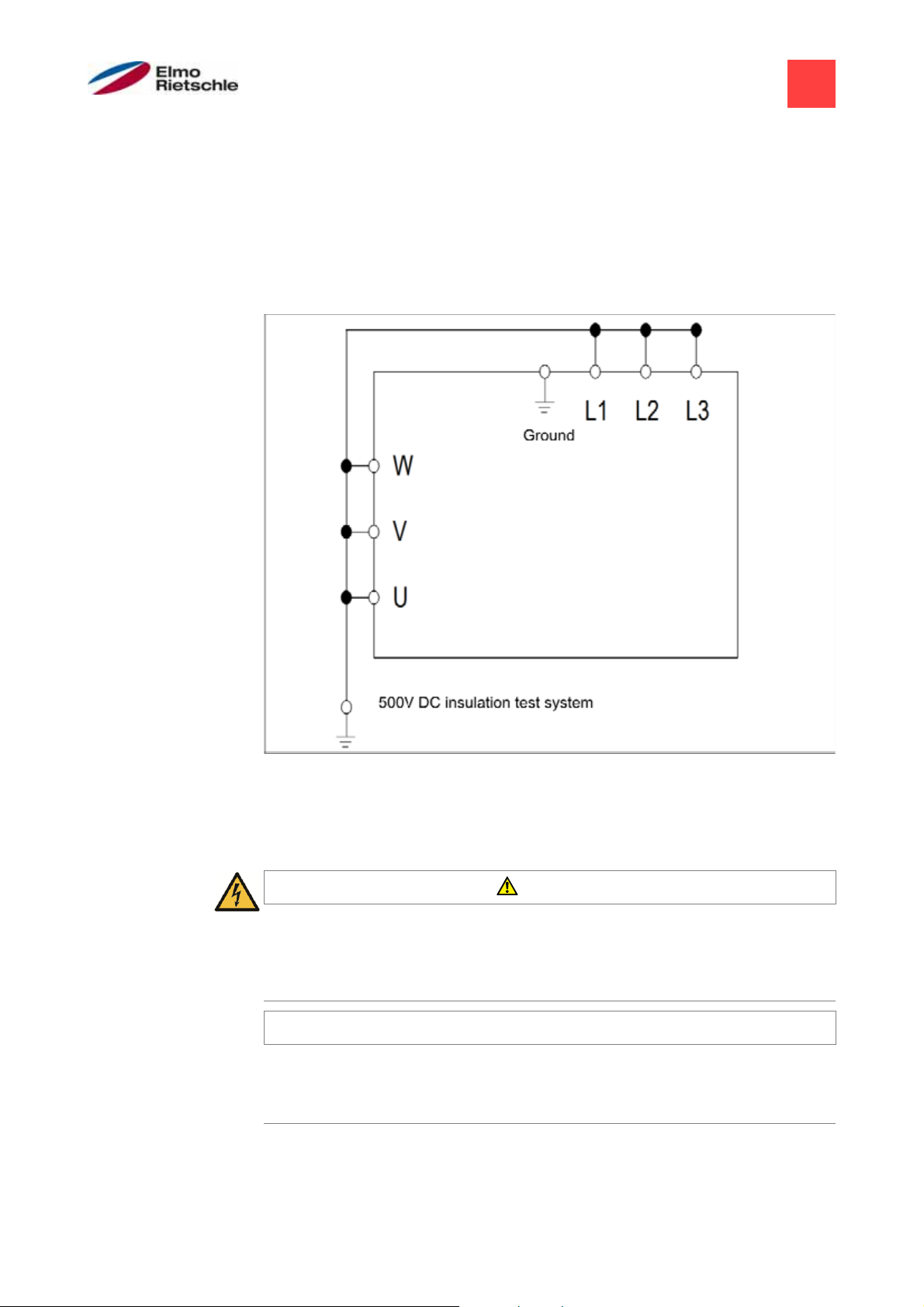
Measurement of insulation resistance on the power unit
In the course of the series testing, the power unit of the drive controller is tested
by applying 1.9 kV.
Should the measurement of insulation resistance be necessary in a system check,
then this can be carried out under the following conditions:
▪ an insulation test can be performed only for the power unit,
▪ to avoid impermissible high voltages, all connecting cables of the drive con-
troller must be disconnected prior to the test,
▪ a 500 V DC insulation tester is used.
Insulation test on the power unit
Pressure test on a DRIVE CONTROLLER
3.2.6
A pressure test of the drive controller is not allowed.
Repairs
DANGER
Danger of injury through electric shock!
Non-observance of warnings may result in serious injury or damage.
When the drive control is disconnected from the mains voltage, live device
parts and connections may not be touched immediately in case the condensers are still live.
NOTICE
Risk of damage to the drive control!
If the information is not observed, the drive control could be damaged and
destroyed during subsequent start-up.
Repairs to the drive control may only be performed by the manufacturer.
© Gardner Denver Deutschland GmbH
11 / 74
05.2014 · 610.00260.40.000
Page 12

3
Safety and responsibility
3.2.7
Disassembly and Disposal
Screw and snap-on connections are easy to release and allow the drive
control to be dismantled into its individual parts. These parts can be sorted
for recycling. Please comply with local regulations during disposal.
Components with electronic parts may not be disposed of along with normal household waste. They have to be collected separately with used electrical and electronic equipment in accordance with applicable legislation.
Correct use of the equipment
3.3
During installation in machinery, commissioning of the drive controller (i.e. starting
of intended operation) is prohibited until it is proven that the machine complies
with the regulations of the EC Directive 2006/42/EC (Machinery Directive); EN
60204-1:2006 is to be observed.
Commissioning (i.e. starting of intended operation) is only permitted if the EC Directive 2004/108/EC (EMC Directive) allows it.
The harmonised standards of the series EN 50178:1997 in conjunction with EN
60439-1/A1:2004 shall be applied to this drive controller.
This drive controller is not approved for operation in potentially explosive areas!
Repairs may only be carried out by authorised repair workshops. Unauthorised interventions can lead to death, bodily injury and property damage. The warranty
provided by the manufacturer expires in this case.
External mechanical loads, such as stepping on the casing are not allowed!
The use of the drive units in non-stationary equipment is considered as unusual environmental conditions, and is permitted only in accordance with
the locally applicable standards and guidelines.
Staff qualifications and training
3.4
All those who will work on the must have read and understood these instructions
and the related documents [➙ 6].
Personnel in training may only work on the under supervision of personnel who
have the required knowledge.
Only allow work on the to be carried out by personnel with the following knowledge:
In the context of this operating manual and the information relating to the product
itself, qualified staff refers to electronic specialists who are familiar with the installation, assembly, start-up and operation of the drive control and the dangers involved, and whose specialist training and knowledge of relevant standards and
regulations provide them with the necessary abilities.
610.00260.40.000 · 05.2014
12 / 74
© Gardner Denver Deutschland GmbH
Page 13

Requirements of the operator
3.5
Safety and responsibility
3
As a basic principle, electronic devices are not fail-proof. The operator and/or the
contractor setting up the machine or system is responsible for ensuring that the
drive switches to a safe state if the device fails.
The “Electrical equipment of machines” section in EN 60204-1, “Safety of machinery” describes the safety requirements for electrical control units. These are
provided for the safety of people and machines and must be observed in order to
retain the functional capability of the machine or system.
An emergency stop feature does not have to result in the power supply to the
drive being switched off. To avoid dangerous situations, it may be useful for individual drives to remain operational or for specific safety procedures to be initiated.
The effectiveness of emergency stop measures is evaluated by means of a risk
assessment for the machine or system and its electrical equipment, and is determined by selecting a circuit category according to EN 13849 “Safety of machinery
– Safety-related parts of control systems”.
The operator ensures that:
▪ All work on the is carried out by:
– personnel that have the necessary Staff qualifications and training [➙ 12]
– personnel that have been sufficiently informed of these instructions and all
related documents [➙ 6]
▪ Assignment, responsibility and supervision of personnel is regulated.
▪ The content of these and locally applicable instructions are always available to
personnel.
▪ All local and plant-specific safety measures are adhered to, such as:
– Prevention of accidents
– safety and operating regulations
– Utility company regulations
– Standards and laws
▪ Dangers due to electrical energy are not possible.
© Gardner Denver Deutschland GmbH
13 / 74
05.2014 · 610.00260.40.000
Page 14

V
4
4
Product identification
Product identification
Model description
4.1
Item designation
1
2FC = drive control
4 Type of assembly:
1 = integrated drive control
2 Connection voltage:
4 = 400 V -15% — 480 V +10%
ersion:
5
ST = Standard
PB = Profibus
PB = Profinet
SC = Sercos III
CB = CANopen
3 Performance:
152 = 1.5 kW
6 reserved:
0 = Standard
222 = 2.2 kW
302 = 3.0 kW
402 = 4.0 kW
552 = 5.5 kW
4.2
752 = 7.5 kW
Description of the drive control
The drive control is a device for speed control in three-phase AC motors.
The drive control can be integrated in the motor (with the standard adapter plate)
or fitted close to the motor (with the wall installation adapter plate).
The permitted ambient temperatures specified in the technical data refer to operation at nominal load. In many cases, higher temperatures may be permitted after a
detailed technical analysis. These have to be approved by manufacturer on a
case-by-case basis.
4.3
610.00260.40.000 · 05.2014
CE marking
With the CE marking, we, as the manufacturer of the device, confirm that the drive
control meets the basic requirements of the following guidelines:
▪ Directive on Electromagnetic Compatibility (Directive 2004/108/EC)
▪ Low Voltage Directive (Directive 2006/95/EC)
You can download the declaration of conformity from www.gd-elmorietschle.com.
14 / 74
© Gardner Denver Deutschland GmbH
Page 15
A
A
5
Installation
Safety instructions for installation
5.1
WARNING
1. Installation may only be performed by appropriately qualified employees who
are trained in the set-up, installation, start-up and operation of the product.
Work performed on the drive control by unqualified staff and non-observance
of warnings may result in serious injury or damage.
2. The device must be grounded in accordance with EN 61140, NEC and other
5.2
5.2.1
relevant standards. Mains connections must be hardwired.
Installation requirements
Suitable ambient conditions
Ambient conditions
ltitude of the installation
site:
Up to 1000 m above sea level [3280 ft above sea level] / over 1000 m
[3280 ft] with reduced performance (1% per 100 m [328 ft]) max. 2000 m
[6560 ft], see
mbient temperature:
-25°C [-13°F] to +50°C [122°F]
(different ambient temperatures may be possible in individual cases) , see
Relative humidity: ≤ 96%, condensation not permitted
Resistance to vibration and
shock:
Electromagnetic compatibil-
acc. to FN 942 017 part 4; 5.3.3.3 Combined test 2;
5...200 Hz for sinusoidal oscillation
Immune to interference acc. to EN 61800-3
ity:
Cooling: Surface cooling:
sizes A to C: free convection;
size D: with integrated fans
! Ensure that the housing type (protection type) is suitable for the operating en-
vironment:
1. Ensure that the seal between the motor and the adapter plate is inserted correctly.
2. All unused cable screw connections must be sealed.
3. Check that the cover of the drive control is closed and bolted down tightly.
Although the drive control can, in principle, be painted later on, the user must
nevertheless check the material compatibility of the intended paint. Failure to
comply with this requirement may eventually result in the loss of the protection
class (particularly in respect to seals and fibre-optic elements). The standard colour is black (RAL 9005).
Disassembling the circuit boards (even for the purpose of painting the housing
sections) renders the warranty void!
Mounting points and sealing surfaces must be kept free of paint for purposes of
EMC and grounding!
Installation
5
© Gardner Denver Deutschland GmbH
15 / 74
05.2014 · 610.00260.40.000
Page 16
5
Installation
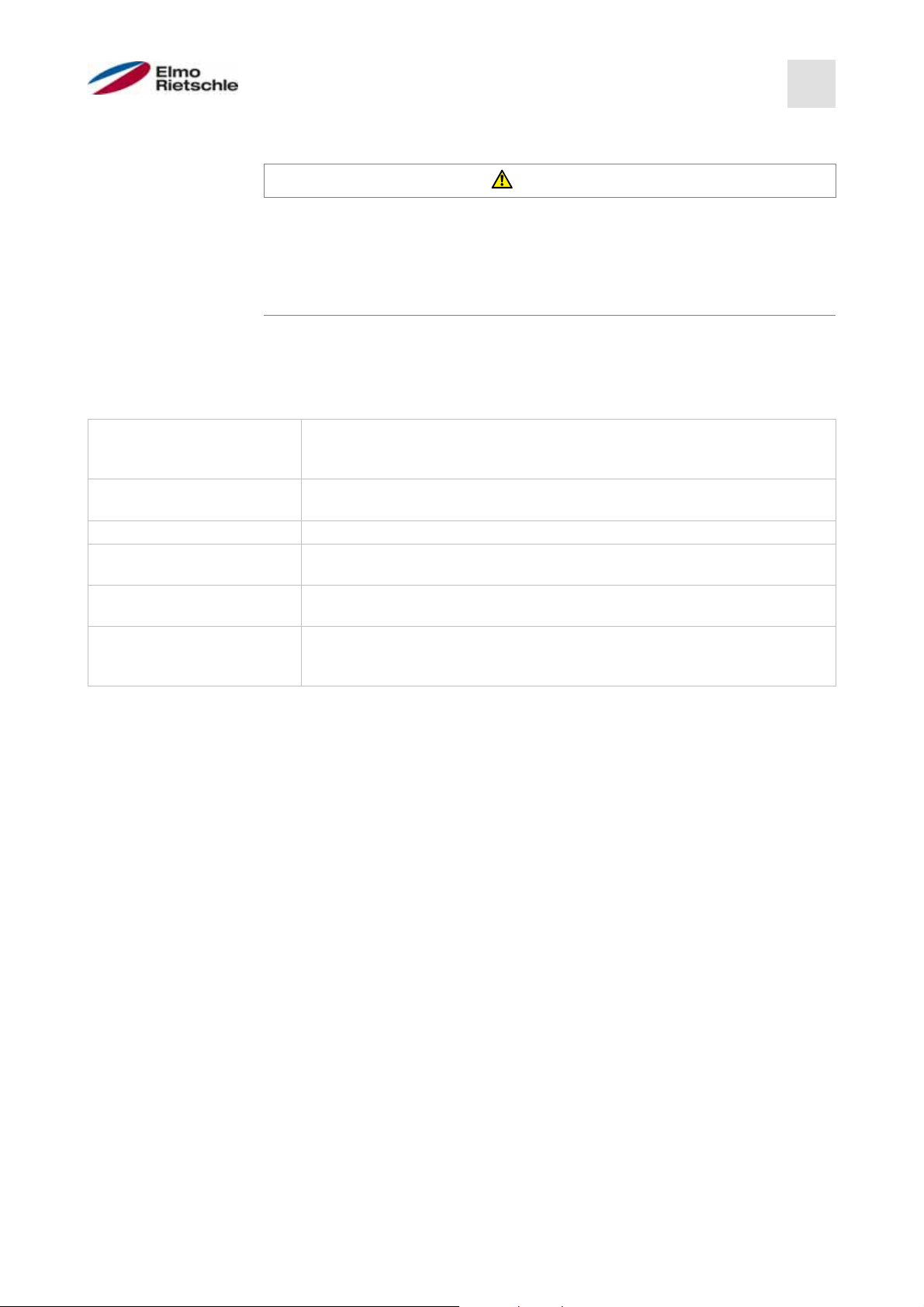
5.2.2
Suitable installation location for the motor-integrated drive
control
Ensure that the motor with a motor-integrated drive control is only installed
and operated if aligned as shown in the following diagram.
5.2.3
Motor installation location/permitted alignments
Basic connection variations
610.00260.40.000 · 05.2014
Star or delta connection with the drive controller integrated in the motor
NOTICE
Risk of damage to the drive controller!
When connecting the drive controller, the correct phase sequence must be
adhered to; otherwise, the motor can be overloaded.
Thus, the correct phase sequence should be ensured when connecting the
motor.
With the supplied installation material, wire-end sleeves and cable lugs can be
connected. The connection options are shown in Figure 4.
16 / 74
© Gardner Denver Deutschland GmbH
Page 17

A
r
Unused open cable ends in the motor connection box must be insulated.
If a PTC or Klixxon is used, the jumper, seated in the terminal for the PTC in
Installation
5
the delivery condition, must be removed.
The cross section of the mains supply line should be designed according to the
type of wiring and the max. current allowed. The mains supply protection must be
5.2.4
5.2.5
ensured by the system start-up engineer.
Short-circuit and earth-fault protection
The drive controller has an internal short-circuit and earth-fault protection.
Wiring instructions
The control terminals of the application card are located inside the drive controller.
Depending on the version, the pins may be allocated differently.
Terminals: Plug-in terminal connector with actuating pusher
(slot-head screwdriver, max. width 2.5 mm [0.098 in])
Connection crosssection:
Connection crosssection:
Connection crosssection:
0.5 to 1.5 mm
single wire, AWG 20 to AWG 14
0.75 to 1.5 mm
fine-wired, AWG 18 to AWG 14
0.5 to 1.0 mm
fine-wired
2
(0.02 to 0.06 inch2),
2
(0.03 to 0.06 inch2),
2
(0.02 to 0.04 inch2),
(wire-end sleeves with and without plastic collar)
Wire stripping length:
9 to 10 mm (0.35 – 0.40 inch)
The terminals for the mains supply line are within the drive controller. The drive
controller is fitted with terminals for connecting a braking resistor.
Depending on the version, the pins may be allocated differently.
Wire-end sleeves with plastic collar and lugs are recommended.
Terminals: Spring-loaded contact (slot-head screwdriver, max.
width 2.5 mm [0.098 in])
Connection crosssection:
Connection crosssection:
Connection crosssection:
Connection crosssection:
rigid 0.2 to 10 mm
flexible wire 0.2 to 6 mm
0.25 to 6 mm
(wire-end sleeves without plastic collar)
0.25 to 4 mm
(wire-end sleeves with plastic collar)
0.25 to 1.5 mm
same cross section
2
, (0.008 – 0.4 inch2)
2
(0.008 – 0.24 inch2)
2
(0.01 to 0.24 inch2)
2
(0.01 to 0.16 inch2)
2
( – 0.06 inch2) for 2 conductors with the
(twin wire-end sleeves with plastic collar)
Wire cross-section:
Wire stripping length:
Installation tempe
ture:
a-
WG 24 to AWG 8
15 mm [0.6 inch]
+5°C to +100°C [41 – 212°F]
© Gardner Denver Deutschland GmbH
17 / 74
05.2014 · 610.00260.40.000
Page 18
5
Installation
5.2.6
Preventing electromagnetic interference
For control circuits shielded cables must be used, where possible. At the cable
end, the shield should be applied with due care without leaving the wires unshielded over longer distances.
The shielding of analogue setpoints should only be applied on one side of the
drive controller.
Basically, the control wires should always be routed as far away as possible from
power cables; separate cable ducts may have to be used, if required. If lines
cross, an angle of 90° should be adhered to, where possible.
Upstream circuit elements, such as contactors and brake coils or circuit elements
which are connected across the outputs of the drive controllers must be suppressed in terms of interference. In AC contactors, RC (resistor-capacitor) circuits
can be used; suppressor diodes or varistors can be normally used for DC contactors. This interference suppressor is attached directly to the contactor coil. Basically, the power supply to a mechanical brake should not be routed in the same
cable!
Power connections between the drive controller and motor should always be used
in shielded or reinforced design and the shield must be earthed at both ends over
a large area! The use of EMC cable glands is recommended. These are not in-
5.3.1
cluded in the delivery.
Installation of the drive controller integrated in the motor
5.3
Mechanical installation of sizes A - C
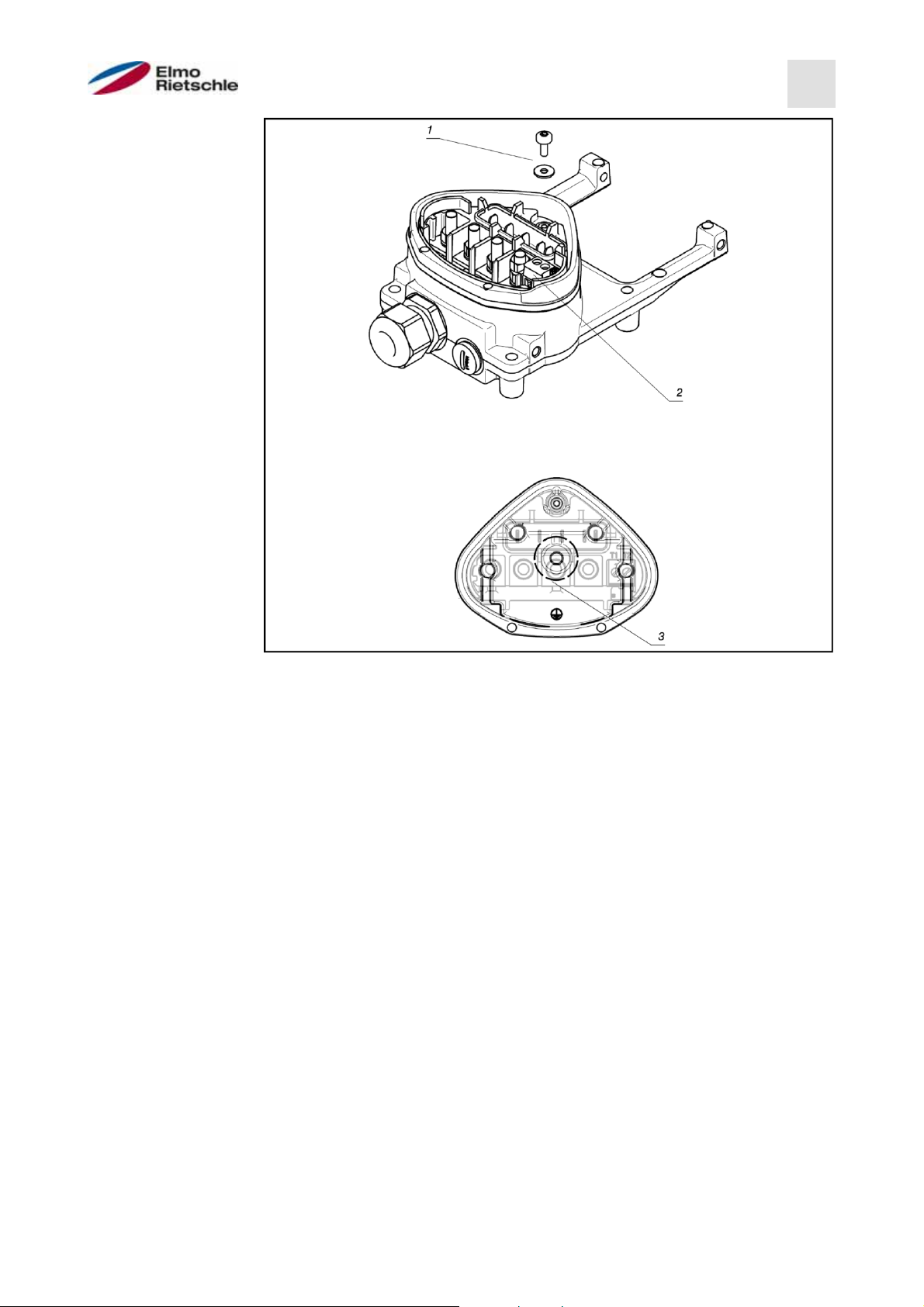
For mechanical installation of the drive controller, proceed as follows:
1. Open the standard motor connection box.
2. Disconnect the wires to the terminals. Remember or write down the connection sequence.
3. If necessary, remove the motor terminal block.
4. Remove the fastening screws securing the housing and remove the housing.
Be careful not to damage the gasket.
610.00260.40.000 · 05.2014
Assembly sequence: Junction box - adapter plate (BG A - C)
18 / 74
© Gardner Denver Deutschland GmbH
Page 19
The standard adapter plate is an adapter plate whose lower part has not
Installation
5
been refinished. No holes are drilled.
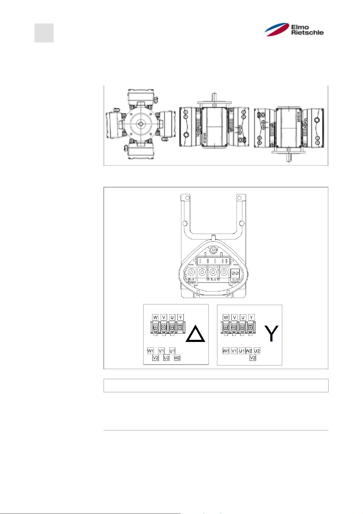
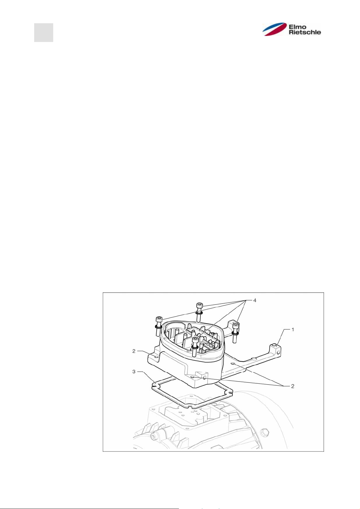
For the motors supplied, you can order adapter plates from the manufacturer.
5. Adjust them to the adapter plate (1) by drilling appropriate holes (2) in them
for attachment to the motor.
The system start-up engineer is responsible for maintaining the protection
class for the gasket of the adapter plate on the motor.
For questions, please contact your sales representative.
6. Insert the gasket (3).
7. Lead the motor connection cable through the adapter plate while bypassing
the terminal and screw the adapter plate onto the motor using four fastening
screws and four spring elements (4) (torque: 2.0 Nm [1.48 ft lbs]).
when mounting the adapter plates, ensure that all four screws, including the
spring elements are tightened by applying the correct torque! All contact
areas must be dirt/ paint-free, as correct protective earth connection cannot be ensured otherwise.
8. Connect the motor wires to the required interconnection, see also Figure 5
(Torque: 3.0 Nm [2.21 ft lbs]). We recommend using insulated M5 ring termi-
2
nals, with a connection cross-section of 4-6 mm
When installing the motor wires make sure that all bolts on the adapter
[0.16 to 0.24 inch2]
board are fitted with the enclosed nuts, even if the neutral point is not connected.
Jumper
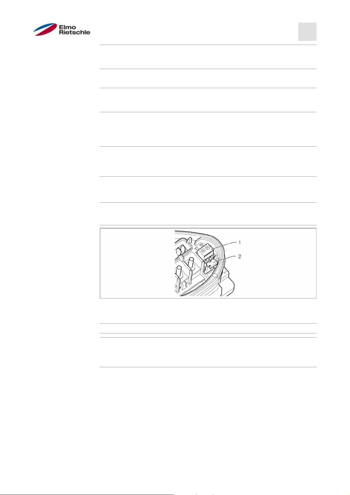
9. Wire any available connection cable of the Motor PTC/ Klixxon to terminals T1
when installing, make sure that the connection cables are not pinched.
If the motor is equipped with a temperature sensor, it is connected to terminals T1 and T2 (1) and the jumper (2) included in the delivery must be removed. If the jumper is used, there is no temperature monitoring of the motor!
10. Plug the drive controller to the adapter plate and secure it evenly using the
© Gardner Denver Deutschland GmbH
and T2 (1) (torque: 0.6 Nm [0.44 ft lbs]).
four screws at the side (torque: 4.0 Nm [0.3 ft lbs]).
19 / 74
05.2014 · 610.00260.40.000
Page 20
5
Installation
5.3.2
Mechanical installation of size D
For mechanical installation of the drive controller, proceed as follows:
1. Open the standard motor connection box.
2. Remove the fastening screws securing the housing and remove the housing.
Be careful not to damage the gasket.
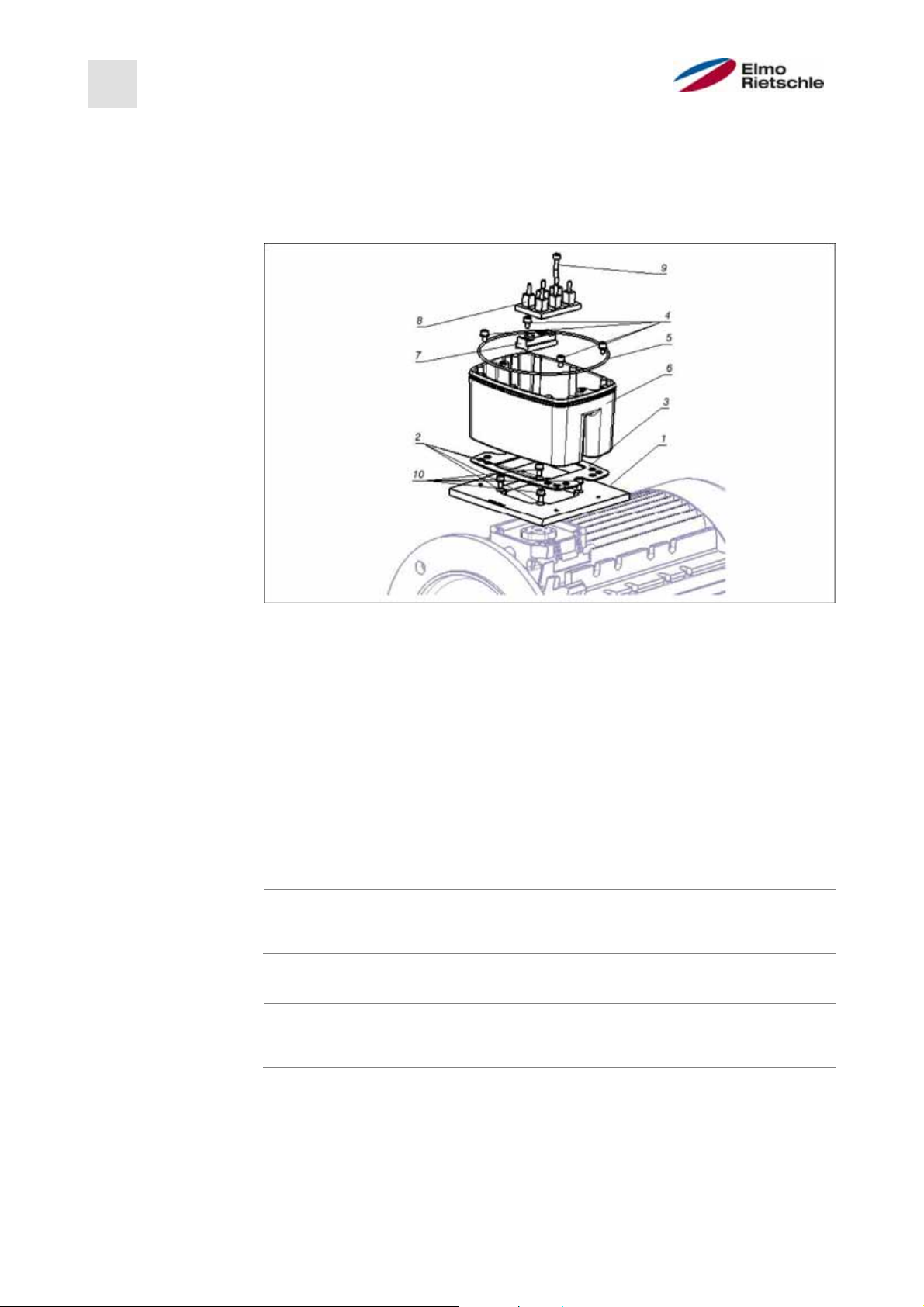
Assembly sequence: Junction box - adapter plate (BG D)
1 Adapter plate option (variant) 6
Support the drive controller /
adapter plate
2 Motor-dependent holes 7 Terminal board expansion option
3 Seal 8
Fastening screws with spring
4
elements
5 O-ring- gasket 10
The standard adapter plate is an adapter plate whose lower part has not
Original terminal board (not included in the delivery)
9 Elongated screw option (for 7)
Fastening screws with spring
elements option
been refinished. No holes are drilled.
For the motors supplied, you can order adapter plates from the manufacturer.
3. Adjust them to the adapter plate (1) by drilling appropriate holes (2) in them
for attachment to the motor.
The system start-up engineer is responsible for maintaining the protection
class for the gasket of the adapter plate on the motor.
For questions, please contact your sales representative.
4. Insert the gasket (3).
5. Screw the adapter plate onto the motor using the four fastening screws and
the four spring elements (10) (torque: M4 with 2.4 Nm [1.77 ft lbs], M5 with
5.0 Nm [3.70 ft lbs], M6 with 8.5 Nm [6.27 ft lbs]).
610.00260.40.000 · 05.2014
20 / 74
© Gardner Denver Deutschland GmbH
Page 21
when mounting the adapter plates, ensure that all four screws, including the
Installation
5
spring elements are tightened by applying the correct torque! All contact
areas must be dirt/ paint-free, as correct protective earth connection cannot be ensured otherwise.
6. Reattach the original terminal board (8) to the motor, possibly with the aid of
the terminal board expansion option (7) and the elongated screw option (9).
7. Connect four wires (PE, U, V, W) with the appropriate cross section (depending on the output of the drive controller used) to the original terminal board.
The connecting wires required for wiring the motor terminal board/ drive
controller are not include in the delivery in the case of spare parts.
8. Screw the support (6) onto the adapter plate using the four fastening screws
with spring elements (4). Please pay attention to the proper seating of the
gasket (5). Insert the four wires (PE, U, V, W) into the support of the drive controller.
9. Plug the drive controller onto the support (6) and secure it evenly using the
two M8 screws
(torque: max. 21.0 Nm [15.5 ft lbs]).
Jumper
10. Wire any available connection cable of the Motor PTC/ Klixxon to terminals T1
and T2 (1) (torque: 0.6 Nm [0.44 ft lbs]).
when installing, make sure that the connection cables are not pinched.
If the motor is equipped with a temperature sensor, it is connected to terminals T1 and T2 (1) and the jumper (2) included in the delivery must be removed. If the jumper is used, there is no temperature monitoring of the motor!
© Gardner Denver Deutschland GmbH
21 / 74
05.2014 · 610.00260.40.000
Page 22
5
Installation
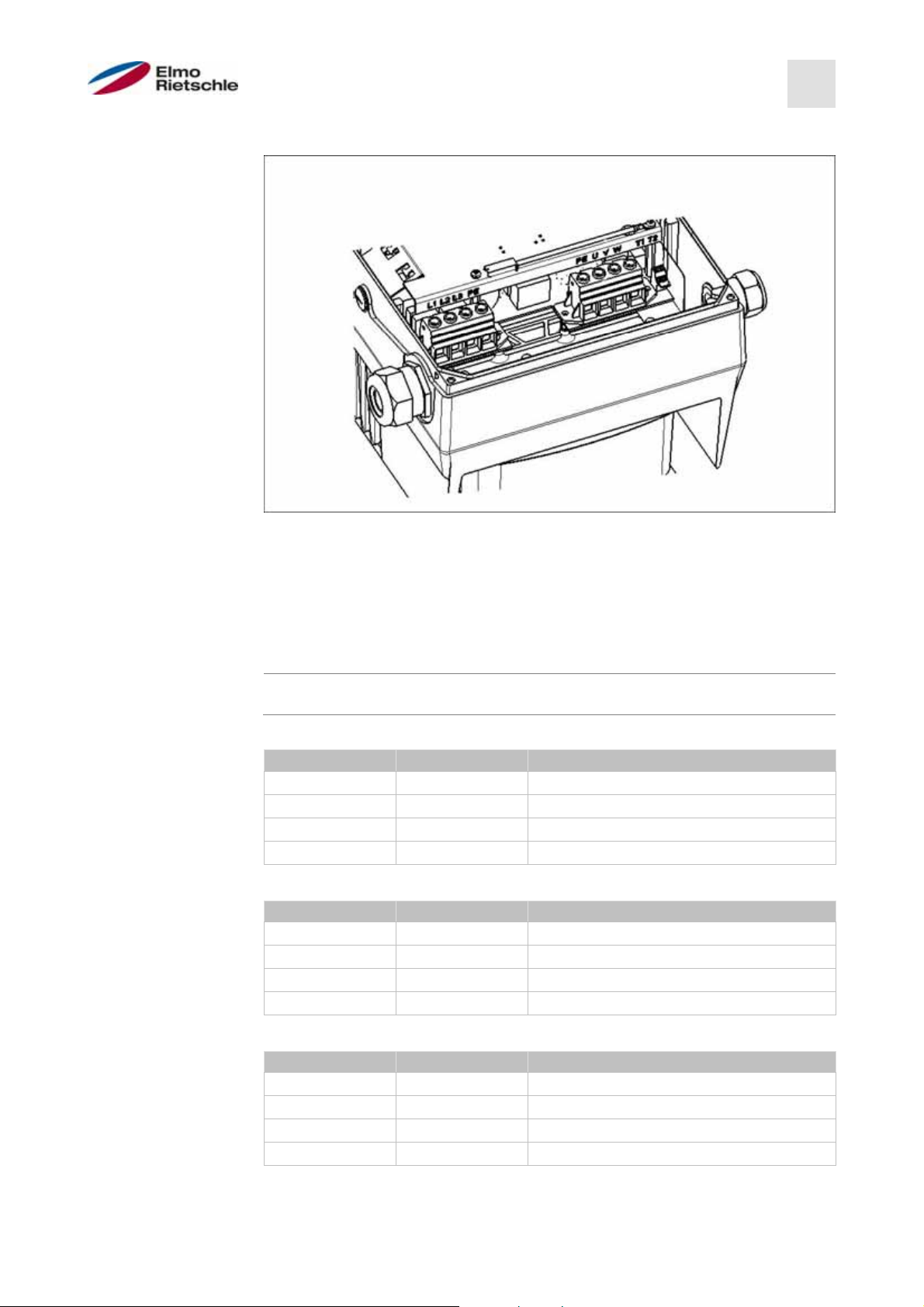
5.3.3
Power connection of sizes A - C
Power connection BG A - C
1. Unscrew the four screws from the housing cover of the drive controller and
remove the cover.
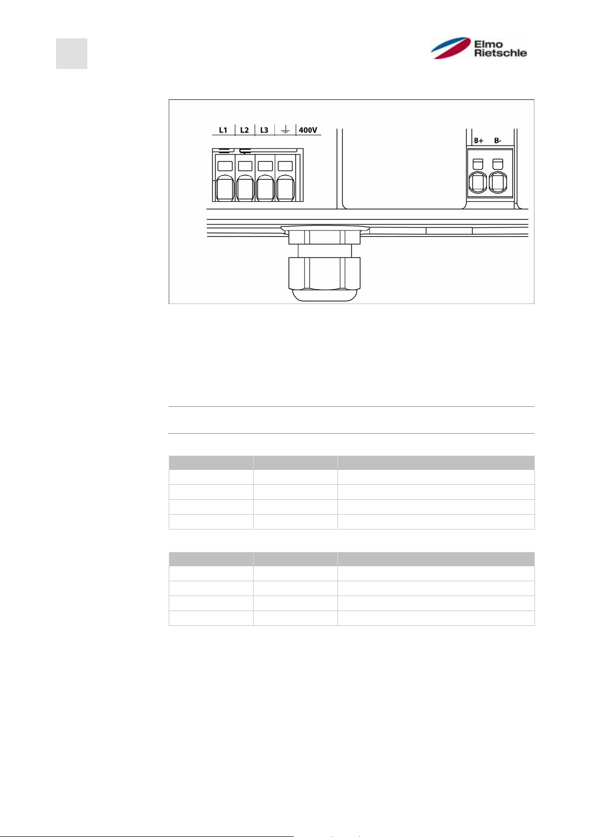
2. Run the mains cable through the threaded cable gland and connect the
phases with the contacts L1, L2, L3 for 400 V and the buried cable with the
PE contact on the terminal. The threaded cable gland provides cable relief,
the PE connection line must be connected as a leading contact (significantly
longer)!
When connecting a braking resistor to an optional brake module, shielded
and double-insulated cables must be used.
3 ~ 400 V terminal assignment X1
Terminal no. Designation (Terminal) assignment
1 L1 Mains phase 1
2 L2 Mains phase 2
3 L3 Mains phase 3
4 PE Buried cable
DC supply 250 to 750 V terminal assignment X1
Terminal no. Designation (Terminal) assignment
1 L1 DC network (+) (565V)
2 L2 Not assigned.
3 L3 DC network (-)
4 PE Buried cable
610.00260.40.000 · 05.2014
22 / 74
© Gardner Denver Deutschland GmbH
Page 23
V
5.3.4
Power connection of size D
Installation
5
Power connection BG D
1. Unscrew the four screws from the housing cover of the drive controller and
remove the cover.
2. Run the mains cable through the threaded cable gland and connect the
phases with the contacts L1, L2, L3 for 400 V and the buried cable with the
PE contact on the terminal. The threaded cable gland provides cable relief,
the PE connection line must be connected as a leading contact (significantly
longer)!
When connecting a braking resistor to an optional brake module, shielded
and double-insulated cables must be used.
3 ~ 400 V terminal assignment X1
Terminal no. Designation (Terminal) assignment
1 L1 Mains phase 1
2 L2 Mains phase 2
3 L3 Mains phase 3
4 PE Buried cable
DC supply 250 to 750 V terminal assignment X1
Terminal no. Designation (Terminal) assignment
1 L1 DC network (+) (565V)
2 L2 Not assigned.
3 L3 DC network (-)
4 PE Buried cable
Motor terminal assignment X4
Terminal no. Designation (Terminal) assignment
1 PE Buried cable
2UMotor phase 1
3
4WMotor phase 3
Motor phase 2
© Gardner Denver Deutschland GmbH
23 / 74
05.2014 · 610.00260.40.000
Page 24
A
A
5
Installation
5.3.5
5.3.6
610.00260.40.000 · 05.2014
Connections for braking resistor
Terminal assignment for braking chopper
Terminal no. Designation (Terminal) assignment
1 B+ Connection of braking resistor (+)
2 B- Connection of braking resistor (-)
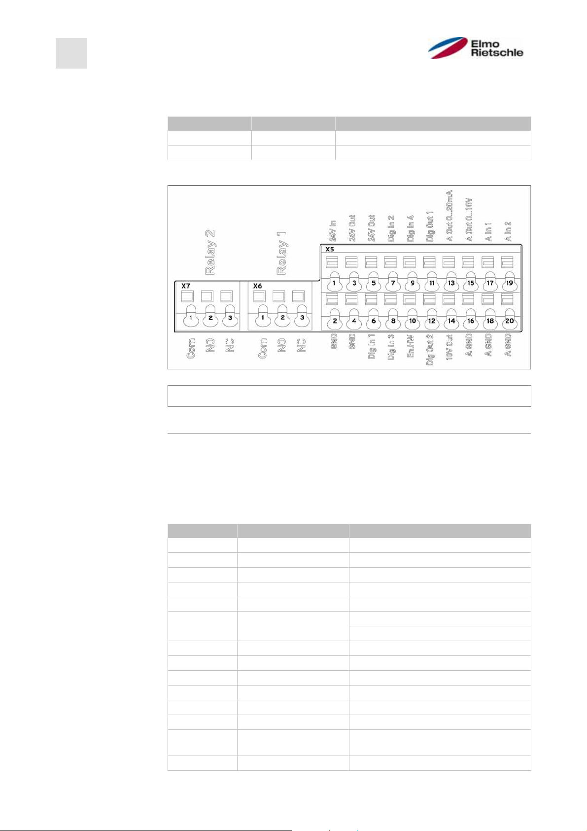
Control terminals
Control terminals of the standard application card
Risk of coupling of external signals!
Use shielded control wires.
1. Pass the required control wires through the threaded cable glands into the
housing.
2. Connect the control wires according to the picture and/or table. To do this,
use shielded control wires.
3. Put the lid on the housing of the drive controller and screw it in place.
Terminal assignment X5 of the standard application card
Terminal no. Designation (Terminal) assignment
1 24 V In External power supply
2 GND (Ground) Ground
3 24 V Out Internal power supply
4 GND (Ground) Ground
5 24 V Out Internal power supply
6 Dig. In 1 fixed frequency 1/3 (parameter 1,100)
7 Dig. In 2 fixed frequency 2/3 (parameter 1,100)
8 Dig. In 3 Fault reset (parameter 1,180)
9 Dig. In 4 External error (parameter 5,010)
10 En -HW (release) Hardware release
11 Dig. Out 1 Ready (parameter 4,150)
12 Dig. Out 2 Operation (parameter 4,170)
13
. Out 0 ... 20 mA
14 10 V Out For external voltage divider
24 / 74
NOTICE
Software release (parameter 1,131)
ctual frequency value (parameter
4,100)
© Gardner Denver Deutschland GmbH
Page 25

A
V
A
A
A
A
A
A
A
Installation
5
Terminal no. Designation (Terminal) assignment
15
. Out 0 ... 10
ctual frequency value (parameter
4,100)
16
17
GND (Ground 10 V) Ground
. In 1 External Setpoint source (parameter
1,130)
18
19
20
GND (Ground 10 V) Ground
. In 2
ctual PID value (parameter 3,060)
GND (Ground 10 V) Ground
Terminal assignment X6 (relay 1)
Terminal no. Designation (Terminal) assignment
1 COM Centre contact relay 1
2 NO Normally open contact relay 1
3 NC Normally closed contact relay 1
In the factory setting, relay 1 is programmed as "fault relay" (parameter
4,190).
Terminal assignment X7 (relay 2)
Terminal no. Designation (Terminal) assignment
1 COM Centre contact relay 2
2 NO Normally open contact relay 2
3 NC Normally closed contact relay 2
In the factory setting, relay 2 is programmed as "fault relay" (parameter
4,210).
5.3.7
Wiring diagram
Control terminals
The drive controller is ready for operation after connection to a 400 V AC power
supply (to the terminals L1 to L3) or after connection to a 565 V DC power supply
(to the terminals L1 and L3).
Alternately, there is the option to put the drive controller in operation by connecting an external 24 V voltage.
The required presetting is described in the chapter "System parameters".
© Gardner Denver Deutschland GmbH
25 / 74
05.2014 · 610.00260.40.000
Page 26
5
Installation
Installing the wall-mounted drive controller
5.4
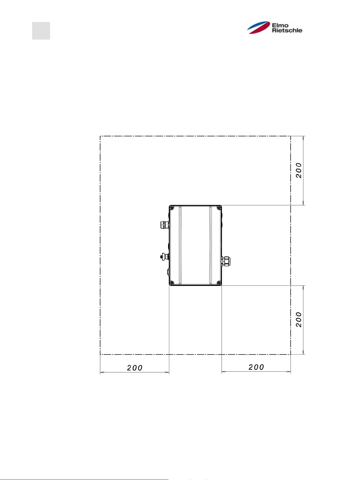
5.4.1
Installation location that is suitable for wall mounting
! Please make sure that the installation location for wall mounting meets the
following conditions:
1. The drive controller must be mounted on a flat, solid surface.
2. The drive controllers may only be mounted on non-combustible surfaces.
3. There must be at least a 20-cm-wide clearance all around the drive controller
to ensure free convection.
The following figure gives you the mounting dimensions and the necessary clearance for the installation of the drive controller.
610.00260.40.000 · 05.2014
Minimum distances
For wall mounting, a maximum line length of 5 m is permitted between the motor
and the drive controller. A shielded cable with the cross section required in each
case should be used. A PE connection should be established (below the terminal
board the wall adapter)!
26 / 74
© Gardner Denver Deutschland GmbH
Page 27
5.4.2
Mechanical installation
Installation
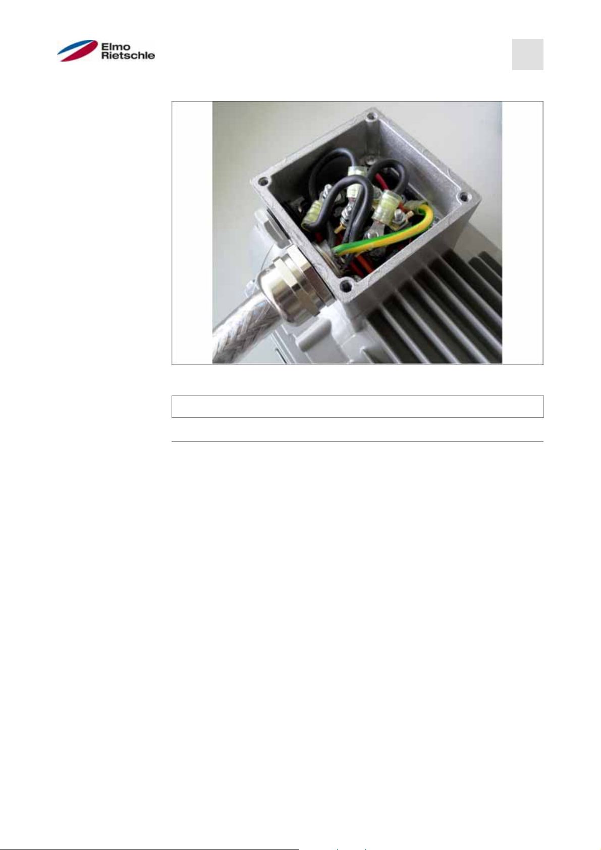
5
Wiring at the motor connection box
1. Open the motor connection box.
NOTICE
Depending on the desired motor voltage, star or delta connection should be
made in the motor connection box.
2. When connecting the shielded motor cable to the motor connection box, use
suitable EMC fittings and ensure proper (large surface) contact with the
shield.
3. Connecting a PE connection to the motor connection box is mandatory.
4. Reconnect the motor connection box.
© Gardner Denver Deutschland GmbH
27 / 74
05.2014 · 610.00260.40.000
Page 28

5
Installation
Mounting the adapter plate to a wall
WARNING
Risk of injury due to incorrect assembly!
The drive controller may not be installed without an adapter plate.
5. Find a location that corresponds to the required ambient conditions, as described in the "Installation requirements" section.
6. In order to achieve optimum self-convection of the drive controller, it must be
ensured during assembly that the (EMC) fitting points upward.
7. Without additional ventilation of the drive controller, only vertical mounting is
allowed.
610.00260.40.000 · 05.2014
28 / 74
© Gardner Denver Deutschland GmbH
Page 29
Installation
5
Wiring
8. Loosen the screw (1) to remove the contact plate from the adapter plate. Below this contact plate is the (M6x15) PE connection (3).
9. Lead the connection cable from the motor via the integrated EMC fitting into
the adapter plate.
10. This PE connection (torque: 4.0 Nm [2.95 ft lbs]) must be connected to the
same earth potential of the motor. The cross section of the equipotential
bonding conductor must correspond to at least the cross-section of the
mains cable.
11. Reattach the contact plate using the screw (1).
12. Wire the motor cable to the contacts U, V and W (possibly also the neutral
point) in the terminal, as described in "Basic connection variations" section.
Use the cable lugs (M5) for this.
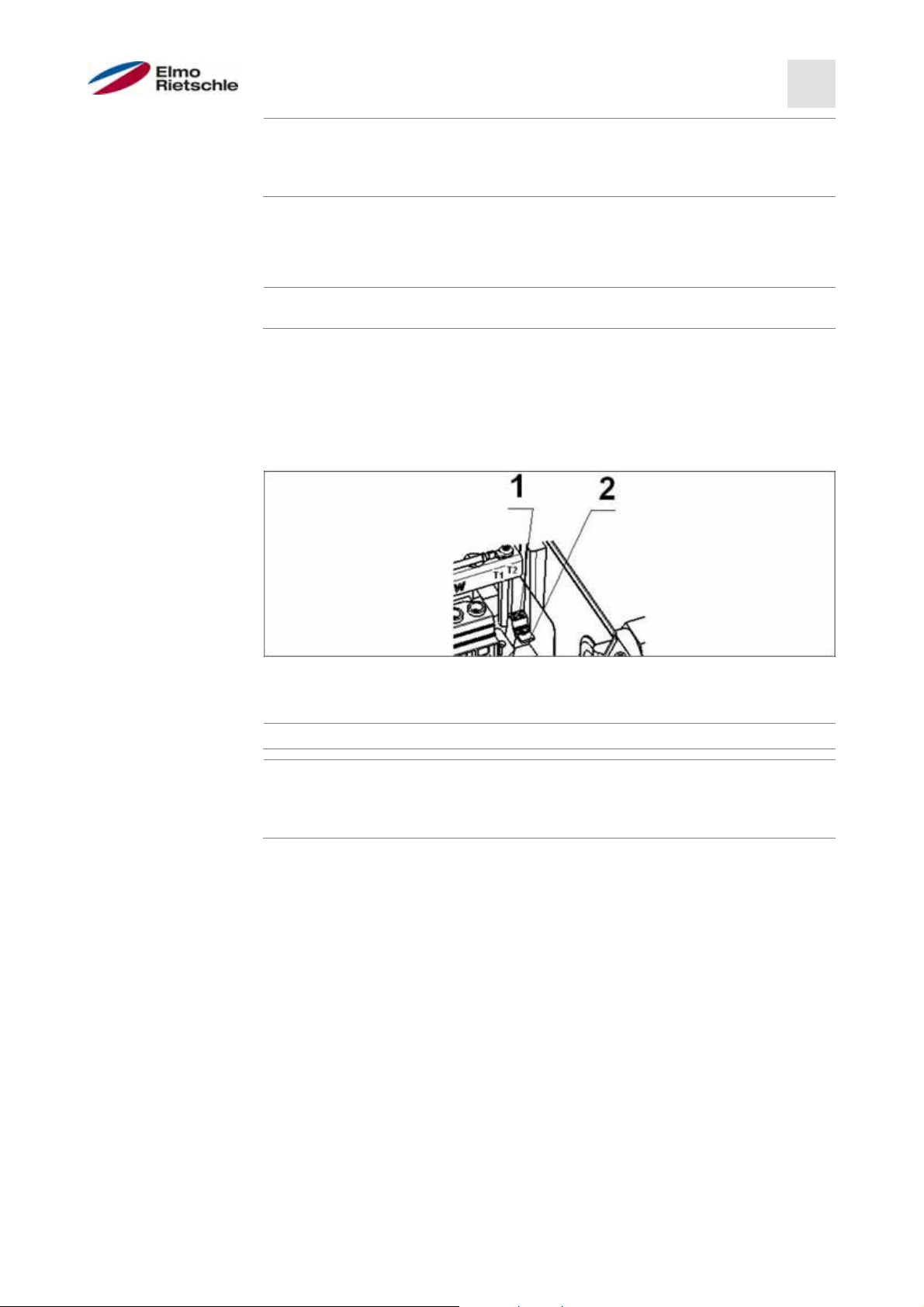
13. Before connecting a possibly existing motor PTC to the terminals T1 and T2,
please remove the pre-assembled jumper (2).
The PTC motor is not electrically isolated following connection of the drive
controller. Therefore, the connection must be made using a separate motor
cable.
To this end, the dummy plug must be replaced with a suitable standard screw
fitting and insert the two ends onto T1 and T2.
© Gardner Denver Deutschland GmbH
29 / 74
05.2014 · 610.00260.40.000
Page 30

5
Installation
Mount the drive controller
14. Place the drive controller (1) on the adapter plate (2) such that the collar of the
adapter dips into the opening at the bottom of the cooling element.
15. Secure the drive controller to the adapter plate using the screws (3) (torque:
5.4.3
4.0 Nm [2.95 ft lbs]).
Power connection
The power connections are made as described in the sections Power connection
5.4.4
of sizes A - C [➙ 22] and Power connection of size D [➙ 23].
Braking chopper
The braking connections are made as described in the section Connections for
5.4.5
braking resistor [➙ 24].
Control terminals
The control terminals are provided as described in the section Control terminals
[➙ 24].
610.00260.40.000 · 05.2014
30 / 74
© Gardner Denver Deutschland GmbH
Page 31

6
Commissioning
Safety information for commissioning
6.1
WARNING
Commissioning
6
Risk of injury!
The non-observance of warnings can result in severe bodily injury or substantial property damage.
1. Make sure that the power supply provides the correct voltage and is designed
for the necessary current.
2. Use suitable circuit breaker with the specified nominal current between the
mains supply and drive controller.
3. Use appropriate fuses with the corresponding current values between the
mains supply and the drive controller (see Technical data [➙ 64]).
4. The drive controller must be correctly earthed to the motor. Not doing so may
result in serious injury.
NOTICE
Risk of damage!
The drive controller can be damaged in the case of non-compliance with
the instructions and destroyed during subsequent handling.
Commissioning may only be carried out by qualified personnel. Safety precau-
tions and warnings must always be observed.
© Gardner Denver Deutschland GmbH
31 / 74
05.2014 · 610.00260.40.000
Page 32

6
Commissioning
Communication
6.2
The drive controller can be put into operation in the following ways:
▪ using the PC software
PC software - start screen
▪ via the hand-held unit MMI
MMI hand-held unit
610.00260.40.000 · 05.2014
32 / 74
© Gardner Denver Deutschland GmbH
Page 33

Block diagram
6.3
Commissioning
6
General structure setpoint generation
© Gardner Denver Deutschland GmbH
33 / 74
05.2014 · 610.00260.40.000
Page 34

6
Commissioning
Commissioning steps
6.4
The drive control can be parameterised on the motor prior to installation.
To this end, the drive controller has a 24-V low-voltage input, which powers
the electronic parts, and without which a mains voltage must be supplied.
Commissioning can be done with a USB PC communication cable to connector
M12 with integrated RS485/RS232 interface converter (2FC4521-0ER00) or via the
MMI hand-held unit, including connection cable RJ11 to connector M12
(2FX4520-0ER00).
6.4.1
Start up the integrated drive control
Prior to delivery, the motor data set was installed on the drive control and requires
no further settings.
With a high signal on terminal strip X5 through the hardware release (En-HW) on
terminal no. 10 and software release on terminal no. 6 (digital input 1), the drive
6.4.2
control can be put into operation (e.g. control via analogue input 1 with 0-10 V).
Commission the drive control wall assembly and replacement
Commissioning with PC
1. Install PC software (you can obtain program software free of charge from the
manufacturer or at www.gd-elmorietschle.de).
Required operating system Windows XP or Windows 7 (32/64 bit). It is recommended to carry out the installation as the administrator.
2. Connect the PC via connection cable to the M12 connector M1.
3. Load the motor data set and continue with the application settings.
OR
determine the motor data set (parameters 33,030 to 33,050). If necessary, optimise the speed controller (parameter 34.100 to 34.101).
610.00260.40.000 · 05.2014
Motor data rating plate (example)
34 / 74
© Gardner Denver Deutschland GmbH
Page 35

Commissioning
6
4. Perform motor identification.
5. Implement application settings (ramps, inputs, outputs, setpoints, etc.).
6. Optional: Define access level (1 - HAND-HELD UNIT MMI, 2 - user 3 - manufacturer).
7. Once all settings have been implemented, with a high signal on terminal strip
X5 through the hardware release (En-HW) on terminal no. 10 and software release on terminal no. 6 (digital input 1), the drive control can be put into operation (e.g. control via analogue input 1 with 0-10 V).
For an optimum operating structure of the PC software, the parameters are divided into access levels. A distinction is made between:
1. Hand-held unit - the drive controller is programmed using the hand-held unit.
2. User - the drive control can be programmed with the basic parameters using
the PC software.
3. User - the drive control can be programmed with an advanced selection of pa-
rameters using the PC software.
Commissioning with the MMI hand-held unit
For commissioning with the MMI hand-held unit, see MMI hand-held unit operating manual [➙ 6].
© Gardner Denver Deutschland GmbH
35 / 74
05.2014 · 610.00260.40.000
Page 36

7
7
Parameters
Parameters
In this chapter, you will find
▪ an introduction to the parameters
▪ an overview of the most important commissioning and operating parameters
Safety instructions for handling the parameters
7.1
WARNING
Risk of injury from restarting motors!
The non-observance of warnings can result in severe bodily injury or substantial property damage.
Certain parameter settings and the changing of parameter settings during
operation can cause the drive controller to restart automatically after a power
7.2
failure, or cause undesirable changes in the operating characteristics.
If parameters are changed during operation, it may take a few seconds before the effect becomes apparent.
General information on parameters
7.2.1
Explanation of operating modes
The operating mode is the instance in which the actual setpoint value is generated. This is a simple conversion of the raw input setpoint value into a speed setpoint in the case of the frequency setting mode and control of a specific process
variable by comparing the setpoint and actual values in the case of the PID process control.
Frequency setting mode:
The setpoints from the "setpoint source" (1,130) are rescaled into frequency setpoints. 0% corresponds to the "minimum frequency" (1,020), 100 % corresponds
to the " maximum frequency" (1,021).
The prefix of the setpoint is the decisive factor in rescaling.
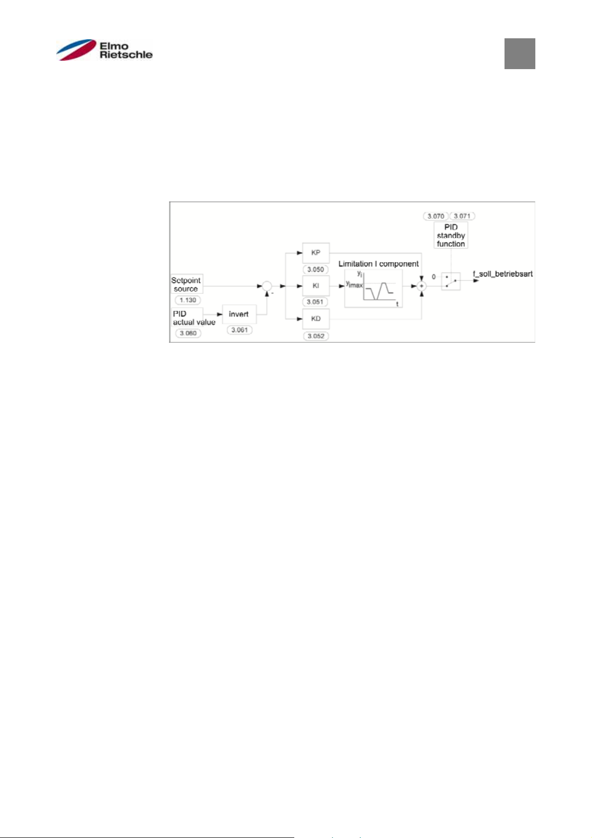
PID process control:
The setpoint for the PID process controller is read as percentage in the "frequency
setting mode" operating mode. 100% corresponds to the working range of the
connected sensor, which is read from the actual value input (selected by the "PID
feedback").
Depending on the control deviation, a speed controller output is issued at the controller output, based on the amplification factors for the P component (3,050), I
component (3,051) and D component (3,052). In order to prevent the increase of
the integral component to infinity in the case of uncontrollable control deviations,
it is also limited to the controller output threshold when reaching the same (corresponds to "maximum frequency" (1,021).
610.00260.40.000 · 05.2014
36 / 74
© Gardner Denver Deutschland GmbH
Page 37
Parameters
7
PID inverse:
Inversion of the PID feedback can be done with the help of parameter 3,061. The
actual value is read inverted, i.e. 0V…10V correspond internally to 100% ... 0%.
Please bear in mind that the setpoint should also be specified inversely!
An example:
A sensor with an analogue output signal (0V…10V) is to be operated as the actual
value source (at AIx). At an output quantity of 7V (70%), it should be regulated inversely. The internal actual value then corresponds to 100% - 70% = 30%. That
is, the setpoint to be specified is 30%.
PID process control
Standby function for PID process control:
This function can be used in applications such as pressure boosting systems, in
which it is controlled to a specific process variable using the PID process control
and the pump should run at a "minimum frequency" (1020) to lead to energy savings. Since the inverter reduces the pump speed with decreasing process variable
during normal operation, but can never go below the "minimum frequency"
(1,020), it is possible to stop the motor when it runs at the "minimum frequency"
(1,020) for a wait time, the "PID standby time" (3,070).
After the actual value deviates from the setpoint by the set % value, the "PID
standby hysteresis" (3,071), the (motor) control is restarted.
© Gardner Denver Deutschland GmbH
37 / 74
05.2014 · 610.00260.40.000
Page 38

7
Parameters
Standby function for PID process control
Fixed frequency:
In this operating mode, fixed frequency setpoints are passed on to the motor control. There are 7 fixed frequencies (2,051 - 2,057) which are linked in BCD format
to the digital inputs 1 to 3. These seven fixed frequencies can be enabled via the
parameter "Auswahl_Festfrequenz(Selection_fixed_frequency)" (2,050) into three
groups:
0 = fixed frequency 1, 1 = fixed frequency 1 to 3, 2 = fixed frequency 1 to 7.
Logic table of fixed frequencies
DI 3 DI 2 DI 1 Selection Parameters Presetting
0 0 1 Fixed fre-
2,051 34 Hz
quency 1
0 1 0 Fixed fre-
2,052 67 Hz
quency 2
0 1 1 Fixed fre-
2,053 50 Hz
quency 3
1 0 0 Fixed fre-
2,054 0 Hz
quency 4
1 0 1 Fixed fre-
2,055 0 Hz
quency 5
1 1 0 Fixed fre-
2,056 0 Hz
quency 6
1 1 1 Fixed fre-
2,057 0 Hz
quency 7
610.00260.40.000 · 05.2014
38 / 74
© Gardner Denver Deutschland GmbH
Page 39

r
7.2.2
Structure of parameter tables
Parameters
7
Example of parameter table
1 Parameter numbe
Description in the parameters
2
manual on page...
6 Unit
Box for entering the inherent
7
value
3 Parameter name 8 Explanation of the parameters
Transfer status
0 = turn on and off to take over
4
the drive controller
1 = at speed 0
Other parameters related to this
9
parameter
2 = in operation
Range of values (from - to - fac-
5
tory setting)
© Gardner Denver Deutschland GmbH
39 / 74
05.2014 · 610.00260.40.000
Page 40

7
Parameters
Application parameter
7.3
7.3.1
Basic parameters
1,020 Minimum frequency Unit: Hz
Relationship to
parameter:
1.150
3.070
Parameter HB:
S. xy
Transfer
status:
2
min: 0 Intrinsic value
max: 400
Def: 25
(to be en-
tered!)
The minimum frequency is the frequency that is supplied by the
drive controller as soon as it is released and no additional setpoint is pending.
This frequency is not reached if
a) it is accelerated from the stationary drive.
b) the FI is locked. The frequency is then reduced to 0 Hz before
it is locked.
c) of the FI is reversed (1,150). Reversing the field of rotation
occurs at 0 Hz.
d) the standby function (3,070) is active.
1,021 Maximum frequency Unit: Hz
Relationship to
parameter:
1.050
1.051
Parameter HB:
S. xy
Transfer
status:
2
min: 5 Intrinsic value
max: 400
Def: see data
(to be en-
tered!)
plate
The maximum frequency is the highest frequency issued by the
converter as a function of the setpoint.
1,050 Braking time Unit: s
Relationship to
parameter:
1.021
1.054
Parameter HB:
S. xy
Transfer
status:
2
min: 0.1 Intrinsic value
max: 1000
Def: Type-
(to be en-
tered!)
specific
The braking time 1 is the time it takes for the inverter to decelerate from the max. frequency (1,021) to 0 Hz.
If the set braking time cannot be met, the fastest possible braking time is implemented.
1,051 Power-up time 1 Unit: s
Relationship to
parameter:
1.021
1.054
Parameter HB:
S. xy
Transfer
status:
2
min: 0.1 Intrinsic value
max: 1000
Def: Type-
(to be en-
tered!)
specific
The power-up time 1 is the time it takes the inverter to accelerate from 0 Hz to the max. frequency.
The power-up time may become longer during certain states,
e.g. overload of the drive controller.
610.00260.40.000 · 05.2014
40 / 74
© Gardner Denver Deutschland GmbH
Page 41

Parameters
7
1,052 Braking time 2 Unit: s
Relationship to
parameter:
1.021
1.054
Parameter HB:
S. xy
Transfer
status:
2
min: 0.1 Intrinsic value
max: 1000
Def: 10
(to be en-
tered!)
The braking time 2 is the time it takes for the inverter to decelerate from the max. frequency (1,021) to 0 Hz.
If the set braking time cannot be met, the fastest possible braking time is implemented.
1,053 Power-up time 2 Unit: s
Relationship to
parameter:
1.021
1.054
Parameter HB:
S. xy
Transfer
status:
2
min: 0.1 Intrinsic value
max: 1000
Def: 10
(to be en-
tered!)
The power-up time 2 is the time it takes the inverter to accelerate from 0 Hz to the max. frequency.
The power-up time may become longer during certain states,
e.g. overload of the drive controller.
1,054 Ramp selection Unit: integer
Relationship to
parameter:
1,050 – 1,053
Parameter HB:
S. xy
Transfer
status:
2
min: 0 Intrinsic value
max: 6
Def: 0
(to be en-
tered!)
Selection of the used pair of ramps.
0 = braking time 1 (1,050) / power-up time 1 (1,051)
1 = braking time 2 (1,052) / power-up time 2 (1,053)
2 = digital input 1 (false = pair of ramps 1 / true = pair of ramps
2)
3 = digital input 2 (false = pair of ramps 1 / true = pair of ramps
2)
4 = digital input 3 (false = pair of ramps 1 / true = pair of ramps
2)
5 = digital input 4 (false = pair of ramps 1 / true = pair of ramps
2)
6 = customer PLC
1,100 Operating mode Unit: integer
Relationship to
parameter:
1,130
1,131
2,051 – 2,057
3,050 – 3,071
Parameter HB:
S. xy
Transfer
status:
2
min: 0 Intrinsic value
max: 3
Def: 0
(to be en-
tered!)
Selection of operating mode.
Following the software release (1,131) and hardware release, the
drive controller runs with the setpoint of the selected setpoint
source (1,130) at
0 = frequency setting mode, with the setpoint of the PID process
controller (3,050 - 3,071) at
1 = PID process controller, with the frequencies specified in the
parameters 2,051 - 2,057 at
2 = fixed frequencies, and via integrated soft PLC at
3 = selection
© Gardner Denver Deutschland GmbH
41 / 74
05.2014 · 610.00260.40.000
Page 42

7
Parameters
1,130 Setpoint source Unit: integer
Relationship to
parameter:
3,062 – 3,069
Parameter HB:
S. xy
Transfer
status:
2
min: 0 Intrinsic value
max: 10
Def: 1
(to be en-
tered!)
Specifies the source from which the setpoint is to be read.
0 = internal potentiometer
1 = analogue input 1
2 = analogue input 2
3 = MANUAL CONTROL UNIT MMI/PC
4 = SAS
6 = motor potentiometer
7 = total analogue inputs 1 and 2
8 = PID fixed setpoints (3,062 - 3,069)
9 = fieldbus
10 = integrated soft PLC
1,131 Software release Unit: integer
Relationship to
parameter:
1,132
1,150
2,050
4,030
4,050
Parameter HB:
S. xy
Transfer
status:
2
min: 0 Intrinsic value
max: 13
Def: 0
(to be en-
tered!)
WARNING! Depending on the change made, the motor
may start to run directly.
Selection of the source for the control release.
0 = digital input 1
1 = digital input 2
2 = digital input 3
3 = digital input 4
4 = analogue input 1 (must be selected in parameter 4,030)
5 = analogue input 2 (must be selected in parameter 4,050)
6 = field bus
7 = SAS
8 = digital input 1 right / digital input 2 left
1,150 must be set to "0"
9 = autostart
10 = integrated soft - PLC
11 = fixed frequency inputs (all inputs that have been selected in
parameter 2,050)
12 = internal potentiometer
13 = membrane keyboard (start & stop buttons)
If the hardware release and a setpoint are applied, the motor
may start to run directly!
This cannot be prevented even with parameter 1,132.
610.00260.40.000 · 05.2014
42 / 74
© Gardner Denver Deutschland GmbH
Page 43

Parameters
7
1,132 Non-tarnish protection Unit: integer
Relationship to
parameter:
1,131
Parameter HB:
S. xy
Transfer
status:
2
min: 0 Intrinsic value
max: 6
Def: 0
(to be en-
tered!)
Selection of characteristics on the control release (parameter
1,131).
No effect if autostart was selected.
0 = immediate start at a high signal at the start input of control
release
1 = start only with increasing slope at the start input of control
release
2 = digital input 1 (function active at high signal)
3 = digital input 2 (function active at high signal)
4 = digital input 3 (function active at high signal)
5 = digital input 4 (function active at high signal)
6 = integrated soft PLC
1,150 Direction of rotation Unit: integer
Relationship to
parameter:
1,131
4,030
4,050
Parameter HB:
S. xy
Transfer
status:
2
min: 0 Intrinsic value
max: 12
Def: 1
Selection of the specified direction of rotation.
(to be en-
tered!)
0 = setpoint-dependent (depending on the prefix of the setpoint:
reverse)
1 = forward only (change in the direction of rotation not possible)
2 = reverse only (change in the direction of rotation not possible)
3 = digital input 1 (0V = forward, 24V = reverse)
4 = digital input 2 (0V = forward, 24V = reverse)
5 = digital input 3 (0V = forward, 24V = reverse)
6 = digital input 4 (0V = forward, 24V = reverse)
7 = integrated soft PLC
8 = analogue input 1 (must be selected in the parameter 4,030)
9 = analogue input 2 (must be selected in parameter 4,050)
10 = membrane keyboard with button for reversal of the direction of rotation (only with running motor)
11 = membrane keyboard with button 1 for forward / 2 for reverse (reverse is always possible)
12 = membrane keyboard with button 1 for forward / 2 for reverse (reverse only possible when the motor is not running)
© Gardner Denver Deutschland GmbH
43 / 74
05.2014 · 610.00260.40.000
Page 44

A
A
r
A
7
Parameters
1,180
Relationship to
parameter:
1.181
1.182
cknowledgement function Unit: integer
Parameter HB:
S. xy
Transfer
status:
2
min: 0 Intrinsic value
max: 5
Def: 3
(to be en-
tered!)
Selects the source for the error acknowledgement.
Errors can only be acknowledged if the error is no longer present.
Certain errors can only be acknowledgement by switching the
controller on and off, see list of errors.
Automatic acknowledgement via parameter 1,181
0 = no manual acknowledgement possible
1 = increasing slope at the digital input 1
2 = increasing slope at the digital input 2
3 = increasing slope at the digital input 3
4 = increasing slope at the digital input 4
1,181
5 = membrane keyboard (Reset button)
utomatic acknowledgement
Unit: s
function
Relationship to
parameter:
1.180
1.182
ameter HB:
Pa
S. xy
Transfer
status:
2
min: 0 Intrinsic value
max: 1000000
Def: 0
(to be en-
tered!)
Besides the acknowledgement function (1,180), automatic fault
acknowledgement can also be selected.
0 = no automatic acknowledgement
1,182
> 0 = time for the automatic reset of the error in seconds
utomatic acknowledgement
Unit:
count
Relationship to
parameter:
1.180
1.181
Parameter HB:
S. xy
Transfer
status:
2
min: 0 Intrinsic value
max: 500
Def: 5
(to be en-
tered!)
In addition to the automatic acknowledgement function (1,181),
the maximum number of automatic acknowledgements can be
limited here.
0 = no limit for the number of automatic acknowledgements
> 0 = number of maximum automatic acknowledgements allowed
7.3.2
Fixed frequency
This mode must be selected in parameter 1,100, see also selection of the operating mode.
2.050 Fixed frequency mode Unit: Integer
Relationship to
parameter:
1.100
2.051 – 2.057
Parameter HB:
Transfer
status:
min: 0 Intrinsic value
max: 3
Def: 1
(to be en-
tered!)
Selection of the digital inputs used for the fixed frequencies.
0 = digital input 1 (fixed frequency 1) (2,051)
1 = digital input 1, 2 (fixed frequencies 1 - 3) (2,051 - 2,053)
2 = digital input 1, 2, 3 (fixed frequencies 1 - 7) (2,051 - 2,057)
3 = membrane keyboard (button 1 = fixed frequency 1 / button 2
610.00260.40.000 · 05.2014
= fixed frequency 2)
44 / 74
© Gardner Denver Deutschland GmbH
Page 45

Parameters
7
2.051 – 2.057 Fixed frequency Unit: Hz
Relationship to
parameter:
1.020
1.021
1.100
1.150
2.050
Parameter HB:
Transfer
status:
min: -400 Intrinsic value
max: +400
Def:
(to be en-
tered!)
2.051: 34
2.052: 67
2.053: 50
The frequencies that should be output at the digital inputs 1 - 3
set in parameter 2,050, depending on the switching pattern.
7.3.3
Motor potentiometer
See fixed frequency, Explanation of operating modes [➙ 36].
This mode must be selected in parameter 1,130. This function can be used both
as a setpoint source for the frequency setting mode as well as for the PID process
controller.
2.150 MOP digital input Unit: Integer
Relationship to
parameter:
1.130
4.030
4.050
Parameter HB:
S. xy
Transfer
status:
2
min: 0 Intrinsic value
max: 8
Def: 0
(to be en-
tered!)
Selection of the source to increase and decrease the setpoint.
0 = digital input 1 + / digital input 2 1 = digital input 1 + / digital input 3 2 = digital input 1 + / digital input 4 3 = digital input 2 + / digital input 3 4 = digital input 2 + / digital input 4 5 = digital input 3 + / digital input 4 6 = analogue Input 1 + / analogue Input 2 - (must be selected in
parameter 4,030 / 4,050)
7 = DRIVE CONTROLLER soft PLC
8 = membrane keyboard (button 1 - / button 2 +)
2.151 MOP increment Unit: %
Relationship to
parameter:
1.020
1.021
Parameter HB:
S. xy
Transfer
status:
2
min: 0 Intrinsic value
max: 100
Def: 1
(to be en-
tered!)
Increment at which the setpoint value is to be changed per keystroke.
2.152 MOP increment time Unit: s
Relationship to
parameter:
Parameter HB:
S. xy
Transfer
status:
2
min: 0,02 Intrinsic value
max: 1000
Def: 0,04
(to be en-
tered!)
Specifies the time in which the setpoint is summed up with permanently present signal.
2.153 MOP response time Unit: s
Relationship to
parameter:
Parameter HB:
S. xy
Transfer
status:
2
min: 0,02 Intrinsic value
max: 1000
Def: 0,3
(to be en-
tered!)
Specifies the time until the present signal is considered to be
permanent.
© Gardner Denver Deutschland GmbH
45 / 74
05.2014 · 610.00260.40.000
Page 46

k
7
Parameters
2.154 MOP retentive Unit: Integer
Relationship to
parameter:
Parameter HB:
S. xy
Transfer
status:
2
min: 0 Intrinsic value
max: 1
Def: 0
(to be en-
tered!)
Determines whether the setpoint of the motor potentiometer is
retained even after power failure.
0 = disabled
1 = enabled
7.3.4
PID process controller
This mode must be selected in parameter 1,100, the setpoint source must be selected in parameter 1,130, see also fixed frequency, Explanation of operating
modes [➙ 36].
3,050 PID P gain Unit:
Relationship to
parameter:
1.100
1.130
Parameter HB:
S. xy
Transfer
status:
2
min: 0 Intrinsic value
max: 100
Def: 0.25
(to be en-
tered!)
Gain factor proportional component of the PID controller.
3,051 PID P gain Unit: s-1
Relationship to
parameter:
1.100
1.130
Parameter HB:
S. xy
Transfer
status:
2
min: 0 Intrinsic value
max: 100
Def: 0.25
(to be en-
tered!)
Gain factor integral component of the PID controller.
3,052 PID P gain Unit: s
Relationship to
parameter:
1.100
1.130
3,060 PID feedbac
Relationship to
parameter:
1,100
1,130
3,061
Parameter HB:
S. xy
Transfer
status:
2
min: 0 Intrinsic value
max: 100
Def: 0
(to be en-
tered!)
Gain factor differential component of the PID controller.
Unit: integer
Parameter HB:
S. xy
Transfer
status:
2
min: 0 Intrinsic value
max: 2
Def: 1
(to be en-
tered!)
Selection of the input source, from which the actual value for the
PID process controller is read.
0 = analogue input 1
1 = analogue input 2
2 = integrated soft PLC
3,061 PID inverse Unit: integer
Relationship to
parameter:
3,060
Parameter HB:
S. xy
Transfer
status:
2
min: 0 Intrinsic value
max: 1
Def: 0
(to be en-
tered!)
The actual value source (parameter 3,060) is inverted.
0 = disabled
1 = enabled
610.00260.40.000 · 05.2014
46 / 74
© Gardner Denver Deutschland GmbH
Page 47

A
Parameters
7
3,062 – 3,068 PID fixed setpoints Unit: %
Relationship to
parameter:
1.100
1.130
Parameter HB:
S. xy
Transfer
status:
2
min: 0 Intrinsic value
max: 100
Def: 0
(to be en-
tered!)
Fixed PID setpoint values that should be output at the digital
inputs 1 – 3 set in parameter 3,069, depending on the switching
pattern (must be selected in parameter 1,130).
3,069 Fixed PID setpoint mode Unit: integer
Relationship to
parameter:
1.100
3.062 – 3.068
Parameter HB:
S. xy
Transfer
status:
2
min: 0 Intrinsic value
max: 2
Def: 0
(to be en-
tered!)
Selection of the digital inputs used for the fixed frequencies.
0 = digital input 1 (fixed PID setpoint 1) (3,062)
1 = digital input 1, 2 (fixed PID setpoint 1-3) (3,062 - 3,064)
2 = digital input 1, 2, 3 (PID fixed setpoint 1-7) (3,062 - 3,068)
3,070 PID standby time Unit: s
Relationship to
parameter:
1,020
Parameter HB:
S. xy
Transfer
status:
2
min: 0 Intrinsic value
max: 10000
Def: 0
(to be en-
tered!)
If the drive controller runs the set time at its minimum frequency
(parameter 1,020), the motor is stopped (0 Hz), see also PID
process control, Explanation of operating modes [➙ 36].
0 = disabled
>0 = wait time until the activation of the standby function
3,071 PID standby hysteresis Unit: %
Relationship to
parameter:
3,060
Parameter HB:
S. xy
Transfer
status:
2
min: 0 Intrinsic value
max: 50
Def: 0
(to be en-
tered!)
Wake-up condition of the PID controller from the standby function.
If the control deviation is greater than the set value in %, the
control restarts, see also operating modes of PID controller.
7.3.5
Analogue inputs
For analogue inputs 1 and 2 (AIx - illustration AI1/AI2)
4.020/4.050
Relationship to
parameter:
Parameter HB:
Ix input type Unit: Integer
S. xy
Transfer
status:
2
min: 1 Intrinsic value
max: 2
Def:
4.020 1
(to be en-
tered!)
4.050 2
Function of the analogue inputs 1/2.
1 = voltage input
© Gardner Denver Deutschland GmbH
2 = current input
47 / 74
05.2014 · 610.00260.40.000
Page 48

A
A
A
A
A
7
Parameters
4.021/4.051
Relationship to
parameter:
Parameter HB:
Ix Norm. Low Unit: %
S. xy
Transfer
status:
2
min: 0 Intrinsic value
max: 100
Def: 0
(to be en-
tered!)
Specifies the minimum value of the analogue inputs as a percentage of the final range value.
Example:
0... 10V or 0... 20 mA = 0 %... 100%
4.022/4.052
Relationship to
parameter:
2... 10V or 4... 20mA = 20%... 100%
Ix Norm. High Unit: %
Parameter HB:
S. xy
Transfer
status:
2
min: 0 Intrinsic value
max: 100
Def: 100
(to be en-
tered!)
Specifies the maximum value of the analogue inputs as a percentage of the final range value.
Example:
0…10V or 0…20mA = 0%…100%
4.023/4.053
Relationship to
parameter:
2…10V or 4…20mA = 20%…100%
lx backlash Unit: %
Parameter HB:
S. xy
Transfer
status:
2
min: 0 Intrinsic value
max: 100
Def: 0
(to be en-
tered!)
Backlash as percentage of final range value of the analogue
4.024/4.054
Relationship to
parameter:
4.030/4.060
Relationship to
parameter:
inputs.
Ix filtering time Unit: s
Parameter HB:
S. xy
Transfer
status:
2
min: 0,02 Intrinsic value
max: 1,00
Def: 0
Filtering time of the analogue inputs in seconds.
lx function Unit: Integer
Parameter HB:
S. xy
Transfer
status:
2
min: 0 Intrinsic value
max: 1
Def: 0
(to be en-
tered!)
(to be en-
tered!)
Function of the analogue inputs ½.
0 = analogue input
1 = digital input
610.00260.40.000 · 05.2014
48 / 74
© Gardner Denver Deutschland GmbH
Page 49

A
A
A
4.033/4.063
Relationship to
parameter:
4.034/4.064
4.035/4.065
Parameter HB:
Ix - physical unit Unit:
Transfer
S. xy
status:
2
Parameters
min: 0 Intrinsic value
max: 10
Def: 0
(to be en-
tered!)
7
Selection of the different physical variables to be displayed.
0 = %
1 = bar
2 = mbar
3 = psi
4 = Pa
3
/h
5 = m
6 = l/min
7 = °C
8 = °F
9 = m
4.034/4.064
Relationship to
parameter:
4.033/4.063
4.035/4.065
10 = mm
lx physical minimum Unit:
Parameter HB:
S. xy
Transfer
status:
2
min: -10000 Intrinsic value
max: +10000
Def: 0
(to be en-
tered!)
Selection of the lower limit of a physical quantity to be dis-
4.035/4.065
Relationship to
parameter:
4.033/4.063
4.035/4.065
played.
Ix - physical maximum Unit:
Parameter HB:
S. xy
Transfer
status:
2
min: -10000 Intrinsic value
max: +10000
Def: 100
(to be en-
tered!)
Selection of the upper limit of a physical quantity to be displayed.
7.3.6
Digital inputs
4.110 – 4.113 DIx inverse Unit: Integer
Relationship to
parameter:
Parameter HB:
S. xy
Transfer
status:
2
min: 0 Intrinsic value
max: 1
Def: 0
(to be en-
tered!)
Using this parameter, the digital input can be inverted.
0 = inactive
1 = active
© Gardner Denver Deutschland GmbH
49 / 74
05.2014 · 610.00260.40.000
Page 50

A
A
A
7
Parameters
7.3.7
Analogue output
4.100
Relationship to
parameter:
4.101
4.102
Parameter HB:
O1 function Unit: Integer
S. xy
Transfer
status:
2
min: 0 Intrinsic value
max: 40
Def: 5
(to be en-
tered!)
Selection of the process value that is output at the analogue
output.
Depending on the process value selected, the standard
(4,101/4,102) must be adapted.
0 = not assigned / DRIVE CONTROLLER soft PLC
1 = intermediate circuit voltage
2 = mains voltage
3 = motor voltage
4 = motor current
5 = actual frequency
6 = speed measured externally by speed sensor (if available)
7 = current angle or position (if available)
8 = IGBT temperature
9 = inner temperature
10 = analogue input 1
11 = analogue input 2
12 = rated frequency
13 = motor power
14 = torque
15 = field bus
16 = PID setpoint (above V3.60)
4.101
Relationship to
parameter:
4.100
17 = PID feedback (above V3.60)
O1 Norm. Low Unit:
Parameter HB:
S. xy
Transfer
status:
2
min: -10000 Intrinsic value
max: +10000
Def: 0
(to be en-
tered!)
Describes the range to be resolved to the output voltage 0 - 10
4.102
Relationship to
parameter:
4.100
V or output current 0 - 20mA.
O1 Norm. High Unit:
Parameter HB:
S. xy
Transfer
status:
2
min: -10000 Intrinsic value
max: +10000
Def: Type-
(to be en-
tered!)
specific
Describes the range to be resolved to the output voltage 0 - 10
V or output current 0 - 20mA.
610.00260.40.000 · 05.2014
50 / 74
© Gardner Denver Deutschland GmbH
Page 51

7.3.8
Digital outputs
For the digital outputs 1 and 2 (DOx - illustration DO1/DO2)
4.150/4.170 DOx function Unit: Integer
Relationship to
parameter:
4.151/4.171
4.152/4.172
4.151/4.171 DOx On Unit:
Relationship to
parameter:
4.150/4.170
4.152/4.172 DOx Off Unit:
Relationship to
parameter:
4.150/4.170
© Gardner Denver Deutschland GmbH
7
Parameter HB:
S. xy
Transfer
status:
2
Parameters
min: 0 Intrinsic value
max: 50
Def:
4.150: 18
(to be en-
tered!)
4.170: 19
Selection of the process variable to which the output should
switch.
0 = not assigned / integrated soft - PLC
1 = intermediate circuit voltage
2 = mains voltage
3 = motor voltage
4 = motor current
5 = actual frequency value
6 = 7 = 8 = IGBT temperature
9 = inner temperature
10 = error (NO)
11 = error inverted (NC)
12 = output stage release
13 = digital input 1
14 = digital input 2
15 = digital input 3
16 = digital input 4
17 = ready for operation
18 = ready
19 = operation
20 = ready for operation + ready
21 = ready for operation + ready + operation
22 = ready + operation
23 = motor power
24 = torque
25 = field bus
26 = analogue input 1 (above V3.60)
27 = analogue input 2 (above V3.60)
28 = PID setpoint (above V3.60)
29 = PID feedback (above V3.60)
50 = motor current limit active
Parameter HB:
S. xy
Transfer
status:
2
min: -10000 Intrinsic value
max: 10000
Def: 0
(to be en-
tered!)
If the set process variable exceeds the switch-on limit, the output is set to 1.
Parameter HB:
S. xy
Transfer
status:
2
min: -10000 Intrinsic value
max: 10000
Def: 0
(to be en-
tered!)
If the set process variable falls below the switch-on limit, the
output is set to 0.
51 / 74
05.2014 · 610.00260.40.000
Page 52

7
Parameters
7.3.9
610.00260.40.000 · 05.2014
Relay
For the relays 1 and 2 (Rel. x - illustration rel. 1/rel. 2)
4.190/4.210 Rel.x function Unit: Integer
Relationship to
parameter:
4.191/4.211
4.192/4.212
4.191/4.211 Rel.x on Unit:
Relationship to
parameter:
4.190/4.210
4.192/4.212 Rel.x off Unit:
Relationship to
parameter:
4.190/4.210
Parameter HB:
S. xy
Transfer
status:
2
min: 0 Intrinsic value
max: 50
Def:
4.190: 11
4.210: 0
Selection of the process variable to which the output should
switch.
0 = not assigned / integrated soft - PLC
1 = intermediate circuit voltage
2 = mains voltage
3 = motor voltage
4 = motor current
5 = actual frequency value
6 = 7 = 8 = IGBT temperature
9 = inner temperature
10 = error (NO)
11 = error inverted (NC)
12 = output stage release
13 = digital input 1
14 = digital input 2
15 = digital input 3
16 = digital input 4
17 = ready for operation
18 = ready
19 = operation
20 = ready for operation + ready
21 = ready for operation + ready + operation
22 = ready + operation
23 = motor power
24 = torque
25 = field bus
26 = analogue input 1 (above V3.60)
27 = analogue input 2 (above V3.60)
28 = PID setpoint (above V3.60)
29 = PID feedback (above V3.60)
50 = motor current limit active
Parameter HB:
S. xy
Transfer
status:
2
min: -10000 Intrinsic value
max: 10000
Def: 0
If the set process variable exceeds the switch-on limit, the output is set to 1.
Parameter HB:
S. xy
Transfer
status:
2
min: -10000 Intrinsic value
max: 10000
Def: 0
If the set process variable falls below the switch-on limit, the
output is set to 0.
52 / 74
© Gardner Denver Deutschland GmbH
(to be en-
tered!)
(to be en-
tered!)
(to be en-
tered!)
Page 53

Parameters
7
4.193/4.213 Rel. x-on delay. Unit: s
Relationship to
parameter:
4.194/4.214
Parameter HB:
S. xy
Transfer
status:
2
min: 0 Intrinsic value
max: 10000
Def: 0
Specifies the duration of the closing delay.
(to be en-
tered!)
4.194/4.214 Rel. x off delay Unit: s
Relationship to
parameter:
4.193/4.213
7.3.10
External error
Parameter HB:
S. xy
Transfer
status:
2
min: 0 Intrinsic value
max: 10000
Def: 0
Specifies the duration of the turn-off delay.
(to be en-
tered!)
5.010/5.011 External error 1/2 Unit: Integer
Relationship to
parameter:
4,110 to 4,113
Parameter HB:
S. xy
Transfer
status:
2
min: 0 Intrinsic value
max: 4
Def:
(to be en-
tered!)
5.010: 4
5.011: 0
Selection of source via which an external error can be reported.
0 = not assigned / integrated soft - PLC
1 = digital input 1
2 = digital input 2
3 = digital input 3
4 = digital input 4
When a high signal exists at the selected digital input, the inverter switches with the error no. 23/24. External error 1/2.
using the parameter 4,110 to 4,113. DIx inverse, the logic of the
digital input can be inverted.
7.3.11
Motor current limit
This function limits the motor current to a programmed maximum value, after
reaching a parametrised current-time area.
This motor current limit is monitored at the application level and thus limited with
relatively small dynamics. This has to be considered in the selection of this function.
The maximum value is determined by the parameter "Motor current limit in %"
(5,070). This is expressed in percentage and is based on the rated motor current
from the type plate data "motor current" (33,031).
The maximum current-time area is calculated as the product of the parameter
"motor current limit in s" (5,071) and the constant over current of 50 % of the desired motor current limit.
As soon as this current-time area is exceeded, the motor current is limited by reducing the rotation speed to the limit value. Thus, if the output current of the drive
controller exceeds the motor current (parameter 33,031) multiplied by the set limit
in % (parameter 5,070) for the set time (parameter 5,071), the motor speed is reduced until the output current drops below the set limit.
The scaling down is done by a PI controller that works depending on the current
difference.
The entire feature can be disabled by setting the parameter "Motor current limit in
%" to zero (5,070).
© Gardner Denver Deutschland GmbH
53 / 74
05.2014 · 610.00260.40.000
Page 54

7
Parameters
5.070 Motor current limit Unit: %
Relationship to
parameter:
5.071
33.031
Parameter HB:
S. xy
0 = disabled
Transfer
status:
2
min: 0 Intrinsic value
max: 250
Def: 0
(to be en-
tered!)
5.071 Motor current limit Unit: s
Relationship to
parameter:
5.070
33.031
Parameter HB:
S. xy
Transfer
status:
2
min: 0 Intrinsic value
max: 100
Def: 1
(to be en-
tered!)
5.075 Transmission factor Unit:
Relationship to
parameter:
33.034
Parameter HB:
S. xy
Transfer
status:
2
min: 0 Intrinsic value
max: 10000
Def: 1
(to be en-
tered!)
Here, a transmission factor can be set.
With the help of the transmission factor, the display of the mechanical speed can be adapted.
7.3.12
610.00260.40.000 · 05.2014
Blocking detection
5.080 Blocking detection Unit: Integer
Relationship to
parameter:
5.081
5.081 Blocking time Unit: s
Relationship to
parameter:
5.080
5.090 Change in the parameter set Unit: Integer
Relationship to
parameter:
Parameter HB:
S. xy
Transfer
status:
2
min: 0 Intrinsic value
max: 1
Def: 0
Using this parameter, the blocking detection can be enabled.
0 = inactive
1 = active
Parameter HB:
S. xy
Transfer
status:
2
min: 0 Intrinsic value
max: 50
Def: 2
Specifies the time after which a blocking is detected.
Parameter HB:
S. xy
Transfer
status:
2
min: 0 Intrinsic value
max: 7
Def: 0
Selection of the active record.
0 = not assigned
1 = record 1, active
2 = record 2, active
3 = digital input 1
4 = digital input 2
5 = digital input 3
6 = digital input 4
7 = integrated soft - PLC
. The second record is displayed on the PC software only if this
parameter is <> 0. The values of the currently selected record
are shown on the display of the hand-held unit.
54 / 74
© Gardner Denver Deutschland GmbH
(to be en-
tered!)
(to be en-
tered!)
(to be en-
tered!)
Page 55

A
Power parameters
7.4
7.4.1
Motor data
Relationship to
parameter:
33.010
Relationship to
parameter:
Relationship to
parameter:
5.070
Relationship to
parameter:
Relationship to
parameter:
34.120
5.075
Relationship to
parameter:
© Gardner Denver Deutschland GmbH
Parameters
33.001 Motor type Unit: Integer
Parameter HB:
S. xy
Selection of the motor type
1 = Asynchronous motor
2 = Synchronous motor
Depending on the motor type selected, the corresponding parameters are displayed.
The control mode (parameter 34,010) must also be chosen accordingly.
33.015 R optimisation Unit: %
Parameter HB:
S. xy
If necessary, the start-up behaviour can be optimised using this
parameter.
33.031 Motor current Unit: A
Parameter HB:
S. xy
Hereby, the rated motor current I
connection.
33.032 Motor power Unit: W
Parameter HB:
S. xy
power value [W] P
must be set here.
33.034 Motor speed Unit: rpm
Parameter HB:
S. xy
Here, the rated motor speed n
motor should be entered.
33.035 Motor frequency Unit: Hz
Parameter HB:
S. xy
The rated motor frequency f
55 / 74
Transfer
status:
1
Transfer
status:
1
Transfer
status:
1
Transfer
status:
1
that is equal to the rated motor power
M,N
Transfer
status:
1
Transfer
status:
1
min: 1 Intrinsic value
max: 2
Def: 1
(to be en-
tered!)
min: 0 Intrinsic value
max: 200
Def: 100
(to be en-
tered!)
min: 0 Intrinsic value
max: 150
Def: Type-
(to be en-
tered!)
specific
is set for either star or delta
M,N
min: 0 Intrinsic value
max: 55000
Def: Type-
(to be en-
tered!)
specific
min: 0 Intrinsic value
max: 10000
Def: Type-
(to be en-
tered!)
specific
from the type plate data of the
M,N
min: 40 Intrinsic value
max: 100
Def: Type-
(to be en-
tered!)
specific
is set here.
M,N
05.2014 · 610.00260.40.000
7
Page 56

7
Parameters
33.050 Stator resistance Unit: Ohm
Relationship to
parameter:
Parameter HB:
S. xy
Transfer
status:
1
min: 0 Intrinsic value
max: 30
Def: Type-
(to be en-
tered!)
specific
Here, the stator resistance can be optimised if the automatically
determined value (on the motor identification) is not sufficient.
33.105 Leakage inductance Unit: H
Relationship to
parameter:
Parameter HB:
S. xy
Transfer
status:
1
min: 0 Intrinsic value
max: 100
Def: 0
(to be en-
tered!)
Only for asynchronous motors.
Here, the leakage inductance can be optimised if the automatically determined value (on the motor identification) is not sufficient.
33.110 Motor voltage Unit: V
Relationship to
parameter:
Parameter HB:
S. xy
Transfer
status:
1
min: 0 Intrinsic value
max: 680
Def: Type-
(to be en-
tered!)
specific
Only for asynchronous motors.
Hereby, the rated motor voltage U
delta connection.
is set for either star or
M,N
33.111 Motor-cos phi Unit: 1
Relationship to
parameter:
Parameter HB:
S. xy
Transfer
status:
1
min: 0,5 Intrinsic value
max: 1
Def: Type-
(to be en-
tered!)
specific
Only for asynchronous motors.
Here, the power factor cosphi from the type plate data of the
motor should be entered.
33.200 Stator inductance Unit: H
Relationship to
parameter:
Parameter HB:
S. xy
Transfer
status:
1
min: 0 Intrinsic value
max: 100
Def: 0
(to be en-
tered!)
Only for synchronous motors.
Here, the stator inductance can be optimised if the automatically determined value (on the motor identification) is not sufficient.
33.201 Rated flow rate Unit: mVs
Relationship to
parameter:
Parameter HB:
S. xy
Transfer
status:
1
min: 0 Intrinsic value
max: 5000
Def: 0
(to be en-
tered!)
Only for synchronous motors.
Here, the rated flow rate can be optimised if the automatically
determined value (on the motor identification) is not sufficient.
610.00260.40.000 · 05.2014
56 / 74
© Gardner Denver Deutschland GmbH
Page 57

7.4.2
I2T
Parameters
7
33,010 I2T factor of the motor Unit: %
Relationship to
parameter:
33.031
33.101
Parameter HB:
S. xy
Transfer
status:
2
min: 0 Intrinsic value
max: 1000
Def: 0
(to be en-
tered!)
Here, the percentage of current threshold (based on the motor
current 33,031) can be adjusted at the start of integration.
33,011 I2T time Unit: s
Relationship to
parameter:
33,100
Parameter HB:
S. xy
Transfer
status:
2
min: 0 Intrinsic value
max: 1200
Def: 25
(to be en-
tered!)
Time after which the drive controller turns off with I2T.
33,138 Holding current time Unit: s
Relationship to
parameter:
33,100
Parameter HB:
S. xy
Transfer
status:
2
min: 0 Intrinsic value
max: 128000
Def: 2
(to be en-
tered!)
Only for asynchronous motors.
Is the time interval during which the drive is maintained with
direct current after stoppage of the braking ramp.
7.4.3
Switching frequency
The internal switching frequency (clock frequency) can be varied to control the
power unit. A high setting value leads to noise reduction in the motor, but also to
increased EMC emission and higher losses in the drive controller.
34.030 Switching frequency Unit: Hz
Relationship to
parameter:
Parameter HB:
S. xy
Transfer
status:
2
min: 1 Intrinsic value
max: 4
Def: 2
(to be en-
tered!)
Selecting the switching frequency of the inverter.
1 = 16 kHz
2 = 8 kHz
7.4.4
Controller data
4 = 4 kHz
34.010 Control mode Unit: Integer
Relationship to
parameter:
33.001
34.011
Parameter HB:
S. xy
Transfer
status:
2
min: 100 Intrinsic value
max: 201
Def: 100
(to be en-
tered!)
Selection of the control mode.
100 = open -loop asynchronous motor
101 = close- loop asynchronous motor
200 = open-loop synchronous motor
201 = close- loop synchronous motor
© Gardner Denver Deutschland GmbH
57 / 74
05.2014 · 610.00260.40.000
Page 58

7
Parameters
34.011 Encoder type Unit: Integer
Relationship to
parameter:
34.010
34.012
34.013
Parameter HB:
S. xy
Transfer
status:
2
Selection of encoder type.
min: 0 Intrinsic value
max: 2
Def: 0
(to be en-
tered!)
0 = inactive
1 = TTL encoder
2 = HTL encoder
NOTICE! When selecting the HTL encoder, 24V is outputted
over the interface. This could lead to the destruction of the
encoder when using a TTL encoder.
34.012 Encoder lines Unit: Integer
Relationship to
parameter:
34.010
34.011
34.013
Parameter HB:
S. xy
Transfer
status:
2
min: 0 Intrinsic value
max: 10000
Def: 1024
Selection of the lines of the encoder used.
(to be en-
tered!)
34.013 Encoder offset Unit: °
Relationship to
parameter:
34.010
34.011
34.012
Parameter HB:
S. xy
Transfer
status:
2
min: 0 Intrinsic value
max: 360
Def: 0
(to be en-
tered!)
Here, an encoder offset can be set for the encoder.
34.021 Snap option Unit: Integer
Relationship to
parameter:
Parameter HB:
S. xy
Transfer
status:
1
min: 0 Intrinsic value
max: 1
Def: 1
(to be en-
tered!)
Using this parameter, the snap option is enabled.
0 = inactive
34.090 n-controller K
Relationship to
parameter:
1 = active
Parameter HB:
S. xy
P
Transfer
status:
2
Unit: mA/rad/s
min: 0 Intrinsic value
max: 10000
Def: 150
(to be en-
tered!)
Here, the controller gain of the speed controller can be optimised if the automatically determined results (on the motor iden-
34.091 n-controller T
Relationship to
parameter:
tification) are not sufficient.
N
Parameter HB:
S. xy
Transfer
status:
2
Unit: s
min: 0 Intrinsic value
max: 10
Def: 4
(to be en-
tered!)
Here, the reset time of the speed controller can be optimised if
the automatically determined results (on the motor identification)
are not sufficient.
610.00260.40.000 · 05.2014
58 / 74
© Gardner Denver Deutschland GmbH
Page 59

V
Parameters
7
34.110 Slip trimmer Unit: Integer
Relationship to
parameter:
33.034
Parameter HB:
S. xy
Transfer
status:
2
min: 0 Intrinsic value
max: 1
Def: 0
(to be en-
tered!)
Only for asynchronous motors.
Using this parameter, the slip compensation can be optimised
or disabled.
0 = disabled (behaviour as on the mains)
34.130
Relationship to
parameter:
1 = the slip is compensated.
oltage control reserve Unit:
Parameter HB:
S. xy
Transfer
status:
2
min: 0 Intrinsic value
max: 2
Def: 0,95
(to be en-
tered!)
Only for asynchronous motors.
7.4.5
Square-law characteristic
The voltage output can be adapted using this parameter.
34.120 Square-law characteristic Unit: Integer
Relationship to
parameter:
34.121
Parameter HB:
S. xy
Transfer
status:
2
min: 0 Intrinsic value
max: 1
Def: 0
(to be en-
tered!)
Only for asynchronous motors.
Here, the function of the square-law characteristic can be enabled.
0 = inactive
1 = active
34.121 Flow adjustment Unit: %
Relationship to
parameter:
34.120
Parameter HB:
S. xy
Transfer
status:
2
min: 0 Intrinsic value
max: 100
Def: 50
(to be en-
tered!)
Only for asynchronous motors.
The percentage by which the flow should be reduced can be set
here.
Very large changes during operation may cause an overvoltage
trip.
7.4.6
Controller data for synchronous motor
34.225 Field weakening Unit: Integer
Relationship to
parameter:
Parameter HB:
S. xy
Transfer
status:
2
min: 0 Intrinsic value
max: 1
Def: 0
(to be en-
tered!)
Only for synchronous motors.
0 = inactive, the motor cannot be run in the weakened field.
1 = active, the motor can be brought into the weakened field
until the inverter has reached its current limit or the max. per-
© Gardner Denver Deutschland GmbH
missible EMC is achieved.
59 / 74
05.2014 · 610.00260.40.000
Page 60

7
Parameters
34.226 Starting current Unit: %
Relationship to
parameter:
34.227
Parameter HB:
S. xy
Transfer
status:
2
min: 5 Intrinsic value
max: 1000
Def: 25
(to be en-
tered!)
Only for synchronous motors.
The flow which is set in the motor prior to its start can be adjusted here. Value in % of the rated motor current.
34.227 Initialisation time Unit: s
Relationship to
parameter:
34.226
Parameter HB:
S. xy
Transfer
status:
2
min: 0 Intrinsic value
max: 100
Def: 0,25
(to be en-
tered!)
Only for synchronous motors.
The time in which the starting current is 34,226 is applied can be
34.228–
set here.
Start-up behaviour Unit: Integer
34.230
Relationship to
parameter:
Parameter HB:
S. xy
Transfer
status:
2
min: 0 Intrinsic value
max: 1
Def: 0
(to be en-
tered!)
Only for synchronous motors.
Larger starting torques can be achieved by changing the startup procedure to the "controlled" mode.
0 = regulated, the inverter switches directly to the control mode
after the setting phase.
1 = controlled, following the setting phase, the field of rotation is
increased to the starting frequency 34,230 controlled with the
start-up ramp 34,229, then it is switched to the regulation mode.
610.00260.40.000 · 05.2014
60 / 74
© Gardner Denver Deutschland GmbH
Page 61

r
8
Error detection and elimination
Error detection and elimination
8
In this chapter, you will find
▪ Display of the LED flash codes for error detection
▪ Description of error detection using PC tools
▪ List of errors and system errors
▪ Notes on error detection using the HAND-HELD UNIT MMI
WARNING
Risk of injury and danger of electric shock!
The non-observance of warnings can result in severe bodily injury or substantial property damage.
1. Repairs on the device may only be carried out by the manufacturer.
2. Any defective parts or components must be replaced using parts included in
the relevant spare parts list.
3. Prior to opening, assembly or disassembly, the drive controller must be
8.1
unlocked.
Display of the LED flash codes for error detection
When an error occurs, the LEDs on the drive controller display a flash code via
which the error can be diagnosed.
The following table gives an overview.
LED flash codes
Red LED Green
Status
LED
Bootloader active (flashing alternately)
Ready for operation (enable En_HW for operation)
LED off
LED flashes
Operation
Warning
Erro
Motor data label
Initialisation
Firmware update
Bus error operation
Bus error ready for operation
LED on
LED flashes quickly
© Gardner Denver Deutschland GmbH
61 / 74
05.2014 · 610.00260.40.000
Page 62

V
8
Error detection and elimination
List of errors and system errors
8.2
When an error occurs, the inverter switches off; for the corresponding error numbers, refer to the flash code table or the PC tool.
Error messages can only be acknowledged when the error is no longer present.
! Error messages can be acknowledged as follows:
1. Digital input (programmable)
2. via the hand-held unit MMI
3. Automatic acknowledgement (parameter 1,181)
4. Switching the device on and off
5. via fieldbus (CANOpen, Profibus DP, EtherCAD)
Below is a list of possible error messages. For errors not listed here, please contact the manufacturer.
Error detection
No. Error name Error description Possible cause / remedy
1 Low voltage 24 V application Supply voltage of the applica-
Overload of the 24 V supply
tion is less than 15 V
2 Over-voltage 24 V application Supply voltage of the applica-
tion is greater than 31 V
3
ersion error of client PLC The version of the client PLC
does not match the device
firmware
4 Communication applica-
tion<>performance
The internal communication
between the application and
Internal 24 V supply is not OK or
external power supply is not OK
Check the version numbers of
the customer PLC and device
firmware
EMC interference
power printed circuit board is
out of order
5 Parameters distributor The internal distribution of the
Parameter set is incomplete
parameters during the initialisation has failed
6 Timeout performance The power unit does not re-
spond
7 Cable breakage analogue input
1 (4 - 20 mA / 2 - 10 V)
Current or voltage is less than
the lower limit of the analogue
Operation with 24 V without
power supply
Cable breakage, defective ex-
ternal sensor
input 1 (this error monitoring is
activated by setting the parameter 4,021 to 20%)
8 Cable breakage analogue input
2 (4 - 20 mA / 2 - 10 V)
Current or voltage is less than
the lower limit of the analogue
Cable breakage, defective ex-
ternal sensor
input 2 (this error monitoring is
activated by setting the parameter 4,021 to 20%)
9 Blocking detection The drive shaft of the motor is
Remove blockage
blocked. 5.080
10 Overtemperature of drive con-
troller application
Internal temperature too high Insufficient cooling, low speed
and high torque, clock fre-
quency too high
11 Bus timeout No response from the bus de-
Check bus wiring
vice or HAND-HELD UNIT MMI /
PC
12 Confirmation error The number of max. automatic
acknowledgements (1,182) has
Check the error history and
eliminate errors
been exceeded
610.00260.40.000 · 05.2014
62 / 74
© Gardner Denver Deutschland GmbH
Page 63

r
r
Error detection and elimination
8
No. Error name Error description Possible cause / remedy
13 External error 1 The parametrised error input is
Eliminate external erro
active. 5.010
14 External error 2 The parametrised error input is
Eliminate external erro
active. 5.011
15 Motor recognition Motor identification errors Check the connections to the
drive controller / motor and PC /
MMI hand-held unit / the drive
controller! Restart of the motor
identification!
16 IGBT trip Protection of the IGBT module
from overcurrent has been trig-
Short circuit in motor or motor
cable / controller settings
gered
17 Intermediate circuit over-voltage The maximum intermediate
circuit voltage has been exceeded
Recovery through motor in re-
generative operation / mains
voltage too high / incorrect set-
ting of the speed controller /
braking resistor is not con-
nected or defective / ramp times
too short
18 Intermediate circuit undervolt-
age
The minimum intermediate circuit voltage was not reached
Mains voltage too low / mains
defective / check wiring
19 Motor overtemperature Motor PTC has been triggered Overload of the motor (e.g. high
torque at low speed) / ambient
temperature too high
20 Interruption in mains supply One phase missing / mains volt-
age supply is interrupted
21 IGBT module overtemperature IGBT module overtemperature Insufficient cooling, low speed
and high torque, clock fre-
quency too high
22 Overcurrent Maximum output current of the
inverter exceeded
Cooling insufficient / low speed
and high torque / clock fre-
quency too high / ramp times
too small / brake not opened
23 Drive controller overtemperature Internal temperature too high Cooling insufficient / low speed
and high torque / clock fre-
quency too high / continuous
overload / reduce ambient tem-
perature / check fan
24 I2T motor protection switch-off The internal I2T motor protection
Continuous overload
(parametrisable) has been triggered
25 Grounding Grounding of a motor phase Insulation fault
26 Motor connection interrupted No motor current despite con-
No motor connected
trol by the drive controller
27 Motor parameter Plausibility check of the motor
Parameter set not OK
parameters has failed
28 Drive controller parameters Plausibility check of the drive
controller parameters has failed
Parameter set not OK, motor
type 33,001 and control mode
34,010 not plausible
29 Type plate data No motor data has been en-
tered.
30 Limitation of power classes Max. overload of the drive con-
troller exceeded for more than
© Gardner Denver Deutschland GmbH
60 seconds.
63 / 74
Enter motor data according to
the rating plate
Check application / reduce load
/ scale-up the drive controller
size
05.2014 · 610.00260.40.000
Page 64

A
V
A
A
9
9
Technical data
Technical data 400 V devices
Technical data
General data
9.1
Size MA MB MC MD
Recommended motor power
1,5 2,2 3,0 4,0 5,5 7,5 11,0 15,0 18,5 22,
(4 -pin asynchronous motor)
mbient temperature
-25°C [-13°F] (non-condensing) up to +50°C [+122°F] (without derating) *
Mains voltage[V] 3~ 400 -10% –480 +10%
Mains frequency [Hz] 4 –63
Line system configurations TN/TT
Mains current [A] 3,3 4,6 6,2 7,9 10,8 14,8 23,3 28,3 33,3 39,
Rated current, effective
4,0 5,6 7,5 9,5 13,0 17,8 28,0 34,0 40,0 48,
[IN at 8 kHz / 400 V]
Minimum braking resistance
100 50 50 30
[Ω]
Maximum overload 150% of rated current for 60 s 13
Switching frequency [kHz] 4, 8, 16 (factory setting 8)
Cyclic frequency [Hz] 0 –400
Protection function Over/undervoltage, I2t limitation, short circuit, motor inverter temperature,
anti-tilt protection, anti-lock system
Process control Freely configurable PID controller
Dimensions
233 x 153 x 120 270 x 189 x 140 307x223x181 414 x 294 x 232
L x B x H [mm]
Weight including adapter
3,9 5,0 8,7 21,0
plate [kg]
Protection class [IPxy] 65 55
EMC met according to DIN EN 61800-3, class C2
*according to UL standard 508C, see Approval according to UL [➙ 73].
Designation Function
Digital inputs 1-4 - Switching level low < 5V / high > 15
- Imax (at 24 V) = 3mA
- Rin = 8.6 kOhm
nalogue inputs 1, 2 - Input +/- 10V or 0 - 20mA -
input 2 - 10V or 4 - 20mA
- resolution 10 bit
- Rin = 10kOhm
Digital outputs 1, 2 - Short-circuit-proof
- Imax = 20 mA
Relay 1, 2 1 changeover contact (NO/ NC)
maximum switching power*:
- for resistive load (cos j = 1): 5 A ~ 230 V or 30 V
- at inductive load (cos j = 0.4 and L/ R = 7 ms): 2 A ~ 230 V or = 30 V
maximum response time: 7 ms ± 0.5 ms
electric service life: 100,000 switching cycles
nalogue output 1 (current) - Short-circuit-proof
- I output = 0 to 20 mA
output load = 500 Ohm
0
9
0
0%
610.00260.40.000 · 05.2014
64 / 74
© Gardner Denver Deutschland GmbH
Page 65

A
V
A
V
A
Designation Function
nalogue output 1 (voltage) - Short-circuit-proof
- Uoutput = 0..10V
- Imax = 10 mA
oltage supply 24 V -
uxiliary voltage U = 24 V DC
- short-circuit-proof
- Imax = 100 mA
- external 24 V supply possible
oltage supply 10 V -
uxiliary voltage U = 10 V DC
- short-circuit-proof
9.2
- Imax = 30 mA
*According to UL standard 508C, max. 2 A is permitted
Derating of output power
The drive controllers are equipped with two built-in PTC resistors (positive temperature coefficient thermistors) that monitor both the cooling element as well as
the internal temperature. Once an allowable IGBT temperature of 95 °C or an allowable internal temperature of 85 °C is exceeded, the drive controller switches
off.
Drive controllers in the power range 1.5 kW - 18.5 kW are designed for an overload of 150% for 60 s (every 10 minutes), the drive controller with rated power of
22 kW for an overload of 130% for 60 s (every 10 min.). For these conditions, reduction of the overload capacity or its time is to be taken into account:
▪ A clock frequency set permanently too high > 8 kHz (depending on load).
▪ A permanently increased cooling element temperature, caused by a blocked
air flow or a thermal block (dirty cooling ribs).
▪ Depending on the installation type, permanently too high ambient tempera-
ture.
The respective max. output values can be defined, based on the following characteristic curves.
Technical data
9
© Gardner Denver Deutschland GmbH
65 / 74
05.2014 · 610.00260.40.000
Page 66

9
Technical data
9.2.1
Derating through increased ambient temperature
Derating for motor-mounted drive controllers (all sizes)
Derating for wall-mounted drive controllers (sizes A - C)
Derating for wall-mounted drive controllers (size C with optional fan and size D)
610.00260.40.000 · 05.2014
66 / 74
© Gardner Denver Deutschland GmbH
Page 67

9.2.2
Derating due to installation altitude
Technical data
9
The following applies to all drive controllers:
▪ In S1 mode, no power reduction is required up to 1,000 m above sea level.
▪ In the range from 1,000 m up to and including 2000 m, power reduction of 1%
is required for every 100 m installation altitude. An overvoltage category 3 is
observed!
▪ In the range from 2,000 m up to and including 4,000 m, the overvoltage cate-
gory 2 must be observed due to the lower air pressure!
To comply with the overvoltage category:
▪ an external surge protector should be used in the mains supply line to the
drive controller.
▪ the input voltage should be reduced.
Please contact the manufacturer.
The respective max. output values can be defined, based on the following characteristic curves.
Derating of the maximum output current due to the installation altitude
Derating of the maximum input voltage due to the installation altitude
© Gardner Denver Deutschland GmbH
67 / 74
05.2014 · 610.00260.40.000
Page 68

9
Technical data
9.2.3
Derating due to the clock frequency
The following illustration shows the output current as a function of the clock frequency. In order to limit the heat losses in the drive controller, the output current
must be reduced.
Note: There is no automatic reduction of the clock frequency!
The max. output values can be defined, based on the following characteristic
curve.
Derating of the maximum output current due to the clock frequency
610.00260.40.000 · 05.2014
68 / 74
© Gardner Denver Deutschland GmbH
Page 69
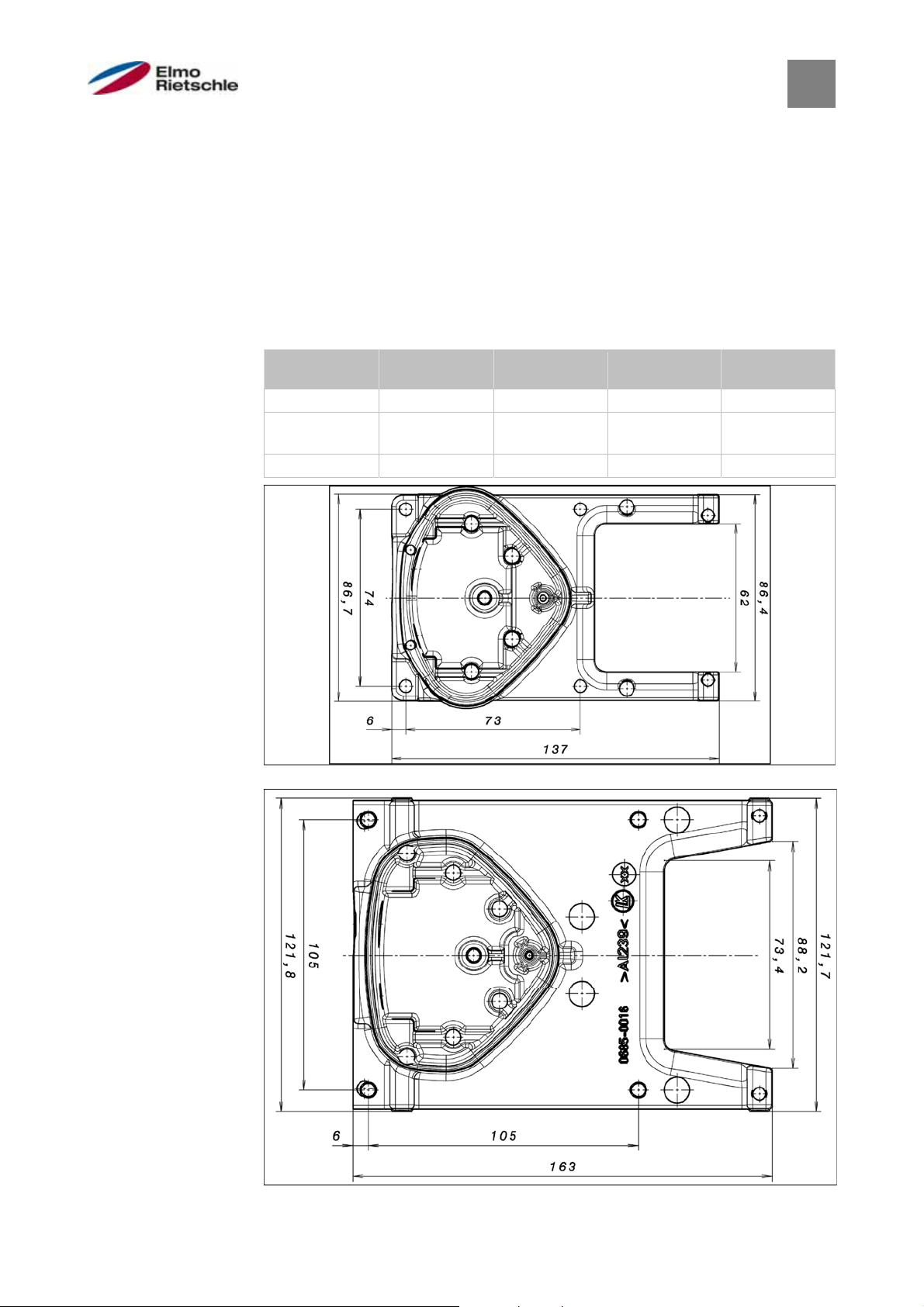
A
10
Optional accessories
Optional accessories
10
In this section, you will find brief descriptions of the following optional accessories
▪ Adapter plates
▪ Hand-held unit MMI, including connection cable RJ11 to connector M12
Adapter plates
10.1
For each DRIVE CONTROLLER size, there is a standard wall-mounted adapter
plate (with integrated adapter board for BG A to BG C).
Download the 3D files for the drive controller and adapter plates at www.gdelmorietschle.com.
Four holes are available for mounting the adapter plate, as well as an EMC cable
gland.
Drive control-
B C D
ler size
Power [kW] 1,5 2,2 –4,0 5,5 – 7,5 11,0 –22,0
Designation 2FX1619-
0ER00
Part no. 1650001619 1650001649 1650001669 1650001699
2FX1649-
0ER00
2FX1669-
0ER00
2FX1699-
0ER00
Drill pattern of standard wall-mounted adapter plate BG A
Drill pattern of standard wall-mounted adapter plate BG B
© Gardner Denver Deutschland GmbH
69 / 74
05.2014 · 610.00260.40.000
Page 70

10
Optional accessories
Drill pattern of standard wall-mounted adapter plate BG C
610.00260.40.000 · 05.2014
Drill pattern of standard wall-mounted adapter plate BG D
70 / 74
© Gardner Denver Deutschland GmbH
Page 71

Hand-held unit MMI, including 3 m connection cable RJ11 to
10.2
Optional accessories
10
connector M12
The hand-held unit MMI 2FX4520-0ER00 is a purely industrial product (accessory)
which may only be used in conjunction with a DRIVE CONTROLLER! The HANDHELD UNIT MMI is connected to the integrated M12 interface of the drive controller. By means of this control unit, the user is able to write (program) and/or display
all parameters of the drive controller. Up to 8 complete records can be stored in a
HAND-HELD UNIT MMI and copied to other DRIVE CONTROLLERS. As an alternative to free PC software, complete commissioning is possible, external signals
are not necessary.
PC communication cable USB to connector M12 (RS485/RS232
10.3
converter integrated)
As an alternative to the MMI hand-held unit, a drive control can also be commissioned with the help of the PC adapter 2FX4521-0ER00 and the PC software. The
PC software is available to you free of cost on the manufacturer homepage under
www.gd-elmorietschle.com.
© Gardner Denver Deutschland GmbH
71 / 74
05.2014 · 610.00260.40.000
Page 72

11
Guidelines, norms and standards
Guidelines, norms and standards
11
This chapter contains information about electromagnetic compatibility (EMC), and
guidelines, norms and standards.
For binding information about the relevant drive control approvals, please refer to
the relevant type plate!
EMC limit classes
11.1
Please note that EMC limit classes are only reached if the standard switching frequency (clocking frequency) of 8 kHz is complied with. Depending on the installation material used and/or extreme ambient conditions, it might be necessary to
use additional sheath wave filters (ferrite rings). If the device is mounted on the
wall, the length of the shielded motor cables (with large surfaces on both sides)
(max. 3 m) may not exceed the permitted limits.
Wiring suitable for EMC also requires that EMC screw connections be used on
both sides (drive control and motor).
In a residential environment, this product can cause high-frequency disruptions that may require interference suppression measures.
NOTICE
Classification acc. to IEC/EN 61800-3
11.2
The generic standard defines test procedures and severity levels for every environment in the drive control category; these have to be complied with.
Definition of environment
First environment (residential, commercial and industrial area):
All “areas” that are directly supplied by a public low-voltage connection, such as:
▪ Residential area, e.g. houses, apartments etc.
▪ Retail area, e.g. shops, supermarkets
▪ Public institutions, e.g. theatres, stations
▪ Outside areas, e.g. petrol stations and parking areas
▪ Light industry, e.g. workshops, laboratories, small businesses
Second environment (industry):
Industrial surroundings with their own supply network that is separated from the
public low-voltage supply by a transformer.
Standards and guidelines
11.3
The following specifically apply:
▪ Directive on Electromagnetic Compatibility (Directive 2004/108/EC of the
Council EN 61800-3:2004)
▪ Low Voltage Directive (Directive 2006/95/EC of the Council EN 61800-5-
1:2003)
▪ Product standards list
610.00260.40.000 · 05.2014
72 / 74
© Gardner Denver Deutschland GmbH
Page 73

A
A
A
A
A
A
A
A
A
A
A
A
Approval according to UL
11.4
Guidelines, norms and standards
11
Required Markings
For installation on industrial machines in accordance with the Standard for Industrial Machinery NFPA79 for recognized components, and NFPA70 for listed components, only. Please check the drives’ name plate for further details.
Maximum Ambient Temperature:
Electronic
INV MA 2 0.37
INV MA 2 0.55
INV MA 2 0.75
INV MA 2 1.1
INV MA 4 1.5
INV MB 4 2.2
INV MB 4 3.0
INV MB 4 4.0
INV MC 4 5.5
INV MC 4 7.5
For listed parts (NFPA70):
Enclosure intended for use with field-installed conduit hubs, fittings or closure
plates UL approved in accordance to UL514B and CSA certified in accordance to
C22.2 No. 18, environmental Type 1 or higher.
The ANTRIEBSREGLER is for use in Pollution Degree 2 only.
Internal Overload Protection Operates within 60 seconds when reaching 150% of
the Motor Full Load Current.
Suitable for use on a circuit capable of delivering not more than 5kA rms symmetrical amperes, 480 Volts for INV Mx 4, maximum when protected by fuses.
“Warning” – Use fuses rated 600V/10A for INV Mx 2 only.
“Warning” – Use fuses rated 600V/30A for INV MB 4 only.
“Warning” – Use fuses rated 600V/30A for INV MC 4 only.
Integral solid state short circuit protection does not provide branch circuit protecttion. Branch circuit protection must be provided in accordance with the Manufacturer Instructions, National Electrical Code and any additional local codes.
All wiring terminals marked to indicate proper connections for the power supply,
load and control circuitry.
The tightening, torque to connect the motor terminals, is 26,55 lb/in and 5,31 lb/in
to connect the PTC.
Instruction for operator and servicing instructions on how to mount and connect
the products using the intended motor connection adapter, please see Installation
of the drive controller integrated in the motor [➙ 18] and Adapter plates [➙ 69].
Use 75oC copper wires only.
Connection of external motor overtemperature sensing is required.
dapter
mbient
DP MA WDM 45°C
DP MA WDM 45°C
DP MA WDM 45°C
DP MA WDM 40°C
DP MA WDM 35°C
DP MB WDM 45°C
DP MB WDM 40°C
DP MB WDM 35°C
DP MC WDM 40°C
DP MC WDM 35°C
© Gardner Denver Deutschland GmbH
73 / 74
05.2014 · 610.00260.40.000
Page 74

 Loading...